application development kit overview - qsl.net application... · 4 mototrbo™ is motorola’s next...
TRANSCRIPT
Version 01.02 4/15/2008
MOTOTRBO™
Application Development Kit Overview
Version 01.02 4/15/2008
COPYRIGHTS
Motorola disclaims any liability for any use of the specification. Motorola limits all warranties to the extent allowed by law. Furthermore, Motorola reserves the right to change this specification at any time without any prior notification, and there is no guarantee that such changes will be backwards compatible with previous versions of the specification.

MOTOTRBO™ Application Development Kit Overview
Version 01.02
TABLE OF CONTENTS Section 1 .................................................................................................................... 4
1.0 What is MOTOTRBO™?................................................................................... 4 Section 2.................................................................................................................... 6 2.0 Extending the MOTOTRBO™ Product ............................................................. 6
2.1 MOTOTRBO™Option Board ADK............................................................. 6 2.2 MOTOTRBO™XCMP-Based IP Capable Peripheral ADK ........................ 8 2.3 MOTOTRBO™ Non- IP Capable Peripheral ADK ..................................... 9 2.4 MOTOTRBO™Telemetry ADK................................................................ 11 2.5 MOTOTRBO™Location Data ADK.......................................................... 13 2.6 MOTOTRBO™Text Messaging ADK ...................................................... 14 2.7 MOTOTRBO™Automatic Registration Service (ARS) ADK .................... 16 2.8 Presence Notifier ..................................................................................... 17 2.9 Data Services .......................................................................................... 18
Section 3.................................................................................................................. 20 3.0 Professional Radio Application Developer Program ....................................... 20 Section 4.................................................................................................................. 22 4.0 Service & Support for Application Development ............................................. 22 Section 5.................................................................................................................. 23 5.0 Further Information and Contact ..................................................................... 23 Section 6.................................................................................................................. 24 6.0 Appendix: ADK Document Map ...................................................................... 24

MOTOTRBO™ Application Development Kit Overview
Version 01.02 4
Section 1 1
1.0 What is MOTOTRBO™? 2 3 MOTOTRBO™ is Motorola’s next generation of Professional Radio that is capable of 4 analog and digital two-way communications. In addition to the standard features 5 available with Motorola’s other analog-based products, MOTOTRBO™ brings digital 6 enhancement to the voice quality as well as an expanded feature set to this product tier. 7 8 While operating in digital mode, MOTOTRBO™ uses a two-slot Time Division Multiple 9 Access (TDMA) air interface to transmit and receive digitized voice and air protocol 10 control messages simultaneously. This leads to a higher quality of service (QoS) and a 11 richer user experience with the product. 12 13 With the digital mode operation of the MOTOTRBO™ system, customers can expect 14 end-to-end operation of advanced features and integrated applications such as text 15 messaging, Location-Based Services (LBS), and telemetry as well as customized 16 capabilities provided through an internal option board. 17

MOTOTRBO™ Application Development Kit Overview
Version 01.02 5
18 Figure 1 - MOTOTRBO™ System Example 19
MOTOTRBO™ Application Development Kit Overview
Version 01.02 6
Section 2 20
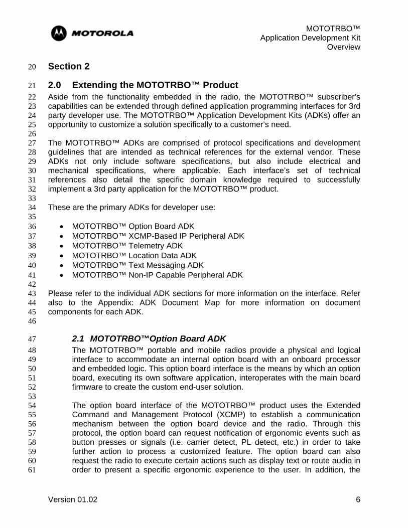
2.0 Extending the MOTOTRBO™ Product 21 Aside from the functionality embedded in the radio, the MOTOTRBO™ subscriber’s 22 capabilities can be extended through defined application programming interfaces for 3rd 23 party developer use. The MOTOTRBO™ Application Development Kits (ADKs) offer an 24 opportunity to customize a solution specifically to a customer’s need. 25 26 The MOTOTRBO™ ADKs are comprised of protocol specifications and development 27 guidelines that are intended as technical references for the external vendor. These 28 ADKs not only include software specifications, but also include electrical and 29 mechanical specifications, where applicable. Each interface’s set of technical 30 references also detail the specific domain knowledge required to successfully 31 implement a 3rd party application for the MOTOTRBO™ product. 32 33 These are the primary ADKs for developer use: 34 35
• MOTOTRBO™ Option Board ADK 36 • MOTOTRBO™ XCMP-Based IP Peripheral ADK 37 • MOTOTRBO™ Telemetry ADK 38 • MOTOTRBO™ Location Data ADK 39 • MOTOTRBO™ Text Messaging ADK 40 • MOTOTRBO™ Non-IP Capable Peripheral ADK 41
42 Please refer to the individual ADK sections for more information on the interface. Refer 43 also to the Appendix: ADK Document Map for more information on document 44 components for each ADK. 45 46
2.1 MOTOTRBO™Option Board ADK 47 The MOTOTRBO™ portable and mobile radios provide a physical and logical 48 interface to accommodate an internal option board with an onboard processor 49 and embedded logic. This option board interface is the means by which an option 50 board, executing its own software application, interoperates with the main board 51 firmware to create the custom end-user solution. 52 53 The option board interface of the MOTOTRBO™ product uses the Extended 54 Command and Management Protocol (XCMP) to establish a communication 55 mechanism between the option board device and the radio. Through this 56 protocol, the option board can request notification of ergonomic events such as 57 button presses or signals (i.e. carrier detect, PL detect, etc.) in order to take 58 further action to process a customized feature. The option board can also 59 request the radio to execute certain actions such as display text or route audio in 60 order to present a specific ergonomic experience to the user. In addition, the 61

MOTOTRBO™ Application Development Kit Overview
Version 01.02 7
option board can activate or de-activate specific functionality, such as scan, the 62 menu system, or an over-the-air data session, to execute the behavior of a new 63 feature. 64 65 The option board interface uses a Synchronous Serial Interface (SSI) to transport 66 the XCMP control and data messages within XCMP Network Layer (XNL) 67 packets to and from the radio and its available services. The SSI is comprised of 68 four logic lines: clock, sync, data in, and data out. The option board uses the SSI 69 to transport logical and audio data to and from the radio. There are no dedicated 70 analog audio lines on the option board interface. Whether the MOTOTRBO™ 71 radio is operating in analog or digital mode, all audio is encoded into digital 72 format and transported on the SSI bus. 73 74 The SSI bus is a multi-slotted Time Division Multiplexed (TDM) communication 75 channel that is shared with other chips and devices contained within or attached 76 to the Radio Host. 77 78
79 Figure 2 - MOTOTRBO™ Option Board Interface Architecture 80
81 Through the MOTOTRBO™ Option Board interface, custom applications can be 82 created to achieve a desired user operation while the MOTOTRBO™ radio is 83 operating in either analog or digital mode. The extended functionality provided by 84 an option board can be a basic ergonomic feature, such as a “Man-Down” lone 85 worker application, or an advanced signal processing feature, such as a custom 86 signaling system format. 87 88 The MOTOTRBO™ Option Board interface also has the extended capability to 89 communicate with other devices within the radio system. This includes Data 90 Applications which are integrated into the Radio Network through a PC 91 environment. These Data Applications communicate using User Datagram 92 Protocol over Internet Protocol (UDP/IP) sent over the Common Air Interface 93 (CAI) of the MOTOTRBO™ Radio. Interoperation with Data Applications is only 94 available while MOTOTRBO™ is operating in digital mode. 95

MOTOTRBO™ Application Development Kit Overview
Version 01.02 8
96 For more information about the MOTOTRBO™ Option Board interface, please 97 see the following references: 98 99
• MOTOTRBO™ Option Board ADK Guide 100 • MOTOTRBO™ Option Board PROIS Cross-reference 101 • MOTOTRBO™ XCMP / XNL Development Guide 102 • MOTOTRBO™ XCMP / XNL Development Specification 103
104 For more information about the other interfaces, please refer to the appropriate 105 sections contained within this overview. 106 107
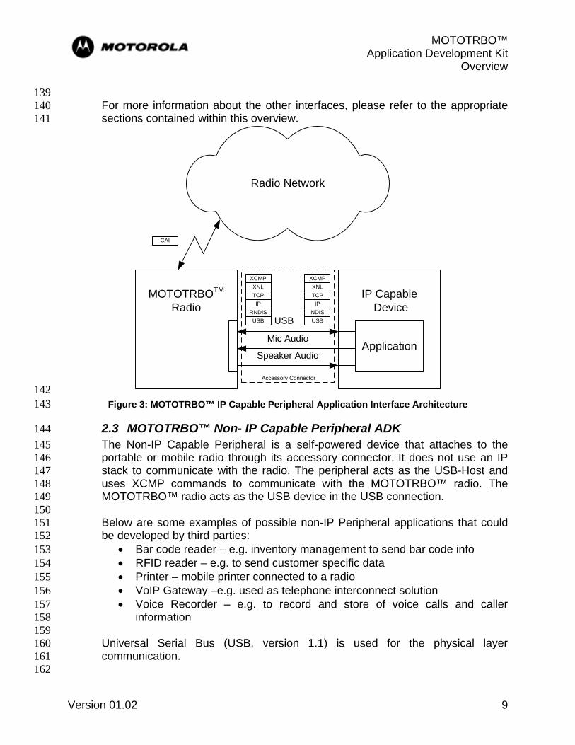
2.2 MOTOTRBO™XCMP-Based IP Capable Peripheral ADK 108 To expand the capability of the MOTOTRBO™ portable and mobile radios, an 109 accessory connector is available as a means to provide external physical and 110 logical interface. This interface allows the radio to function as a USB device 111 attached to an IP capable peripheral. 112 113 The MOTOTRBO™ radio is able to send/receive XCMP/XNL message from an 114 external IP capable device via a unique TCP port. The radio attached to the 115 external IP capable device executes the XCMP commands from the external 116 application and reports the status change. 117 118 Although it operates as a USB device when an external IP capable device 119 connects through the radio accessory connector, the MOTOTRBO™ subscriber 120 is still considered a master device within the XCMP/XNL architecture. 121 122 When communicating with the radio’s XCMP/XNL interface, the external IP 123 capable device becomes an XCMP device. Therefore it can even directly 124 communicate with other XCMP devices connected to the radio, for example, the 125 Option Board through XCMP/XNL message. 126 127 As an example, Figure 3 illustrates the interface architecture for the 128 MOTOTRBO™ IP capable peripheral with an XCMP-based application. 129 130 For more information about the XCMP IP capable peripheral and also its 131 operation with other applications offered by the MOTOTRBO™ radio, please see 132 the following references: 133 134
• MOTOTRBO™ XCMP Development Guide 135 • MOTOTRBO™ XCMP Developer Specification 136 • MOTOTRBO™ ADK Data Services Overview 137 • MOTOTRBO™ Third Party Peripheral Cable ADK 138
MOTOTRBO™ Application Development Kit Overview
Version 01.02 9
139 For more information about the other interfaces, please refer to the appropriate 140 sections contained within this overview. 141
MOTOTRBOTM
RadioIP Capable
Device
Mic Audio
Speaker Audio
USB
Radio Network
CAI
Application
Accessory Connector
TCPXNL
XCMP
IP
USBRNDIS
TCPXNL
XCMP
IP
USBNDIS
142 Figure 3: MOTOTRBO™ IP Capable Peripheral Application Interface Architecture 143
2.3 MOTOTRBO™ Non- IP Capable Peripheral ADK 144 The Non-IP Capable Peripheral is a self-powered device that attaches to the 145 portable or mobile radio through its accessory connector. It does not use an IP 146 stack to communicate with the radio. The peripheral acts as the USB-Host and 147 uses XCMP commands to communicate with the MOTOTRBO™ radio. The 148 MOTOTRBO™ radio acts as the USB device in the USB connection. 149 150 Below are some examples of possible non-IP Peripheral applications that could 151 be developed by third parties: 152
• Bar code reader – e.g. inventory management to send bar code info 153 • RFID reader – e.g. to send customer specific data 154 • Printer – mobile printer connected to a radio 155 • VoIP Gateway –e.g. used as telephone interconnect solution 156 • Voice Recorder – e.g. to record and store of voice calls and caller 157
information 158 159 Universal Serial Bus (USB, version 1.1) is used for the physical layer 160 communication. 161 162

MOTOTRBO™ Application Development Kit Overview
Version 01.02 10
The CDC/ACM class driver is used as the USB device stack to communicate with 163 the Non-IP Capable Peripheral USB system driver. 164 165 XCMP/XNL is used as the application communication protocol between the Non-166 IP Capable Peripheral and the MOTOTRBO™ radio. The Non-IP Capable 167 Peripheral is considered a non-master device within the XCMP/XNL architecture. 168 The XCMP/XNL protocol provides a set of commands for an external device to 169 control and manage the MOTOTRBO™ radios. 170 171 The USB and XNL connections are independent of the analog/digital RF modes 172 of operation. The Non-IP Capable peripheral does not need to re-establish the 173 USB or XNL connections after mode change. 174 175 As an example, Figure 4 illustrates the interface architecture for the 176 MOTOTRBO™ Non-IP capable peripheral. 177 178
179 Figure 4: MOTOTRBO™ Non-IP Capable Peripheral Application Interface Architecture 180 181 For more information about the Non-IP capable peripheral and also its operation 182 with other applications offered by the MOTOTRBO™ radio, please see the 183 following references: 184 185
• MOTOTRBO™ XCMP Development Guide 186 • MOTOTRBO™ XCMP Developer Specification 187 • MOTOTRBO™ Third Party Peripheral Cable ADK 188 • MOTOTRBO™ ADK Data Services Overview 189
190
Application
XCMP
XNL (Slave)
CDC ACM
USB Host
Application
XCMP
XNL (Master)
CDC ACM
USB Device
Non-IP Capable Peripheral MOTOTRBO Radio
USB Cable

MOTOTRBO™ Application Development Kit Overview
Version 01.02 11
For more information about the other interfaces, please refer to the appropriate 191 sections contained within this overview. 192 193
2.4 MOTOTRBO™Telemetry ADK 194 The MOTOTRBO™ product can be customized for telemetry operation by 195 developing a PC-based application using the MOTOTRBO™ Telemetry interface. 196 A Telemetry Services PC application interoperates with a MOTOTRBO™ radio 197 via direct USB connection and can monitor or control the general purpose inputs 198 and outputs (GPIOs) of a radio. Telemetry operation is available while the 199 MOTOTRBO™ product is operating in digital mode only. 200 201 Telemetry operation is available on 3 GPIOs for the MOTOTRBO™ portable and 202 on 5 GPIOs for the MOTOTRBO™ mobile. The status of telemetry events can be 203 queried for inputs or outputs. The state transition of telemetry inputs can also be 204 announced and shown on a display-capable MOTOTRBO™ radio. 205 206 Routing of telemetry information in the radio network is accomplished using 207 UDP/IP. The destination of the telemetry data can be either to a Telemetry 208 Services PC application or to another device such as an option board. The 209 Telemetry interface can also broadcast telemetry status over-the-air to specific 210 MOTOTRBO™ subscribers within the radio network. 211 212

MOTOTRBO™ Application Development Kit Overview
Version 01.02 12
Telemetry Services
Application
PC Environment
MOTOTRBOTM
Radio
Radio Network
MOTOTRBOTM
Radio Sensors & ControlGPIO
TPUDP
IPRNDISUSB
TPUDP
IPCAI
TPUDP
IPCAI
GPIO
213 Figure 5 – MOTOTRBO™ Telemetry Interface Architecture 214
215 The Telemetry interface enables remote detection or activation of events through 216 the MOTOTRBO™ system. An example of a telemetry-based solution is an 217 irrigation system that is automatically activated based on average moisture level. 218 219 For more information about the MOTOTRBO™ Telemetry interface, please see 220 the following references: 221 222
• MOTOTRBO™ Telemetry ADK Guide 223 • MOTOTRBO™ Telemetry Protocol Specification 224 • MOTOTRBO™ Data Services Overview 225

MOTOTRBO™ Application Development Kit Overview
Version 01.02 13
• MOTOTRBO™ Third Party Peripheral Cable ADK 226 227 For more information about the other interfaces, please refer to the appropriate 228 sections contained within this overview. 229 230
2.5 MOTOTRBO™Location Data ADK 231 The MOTOTRBO™ product features optional embedded GPS capability for 232 Location-Based Services (LBS) with the portable and mobile radio. The location 233 function provides latitude, longitude, altitude, velocity, and heading data for the 234 radio. A LBS PC application can also interoperate with the MOTOTRBO™ 235 product to record a timestamp of reported location data for any specified radio. 236 The Location Data interface is available while the MOTOTRBO™ product is 237 operating in digital mode only. 238 239 Location status can be configured for periodic or on-request reporting during 240 normal operation. During emergency operation, the MOTOTRBO™ radio can be 241 configured for more frequent reporting of location data. 242 243
LBS Application
MOTOTRBOTM
Radio
LRRPUDP
IPRNDISUSB
Radio Network
MOTOTRBOTM
Radio
GPSComponent
LRRPUDP
IPCAI
LRRPUDP
IPCAI
LRRP
PC Environment
244 Figure 6 – MOTOTRBO™ Location Data Interface Architecture 245

MOTOTRBO™ Application Development Kit Overview
Version 01.02 14
Messages for requests and responses for location data are handled through the 246 Location Request and Response Protocol (LRRP). LRRP is a location data 247 reporting protocol that is optimized for use within the MOTOTRBO™ Radio 248 Network. LRRP control and data messages are sent via the Radio Network within 249 UDP/IP packets that are transported over the Common Air Interface (CAI). The 250 LRRP messages are processed directly by the embedded GPS components 251 inside the MOTOTRBO™ radio as well as within the LBS PC application. The 252 Location Data interface can also interoperate with the MOTOTRBO™ Option 253 Board interface to route location data directly to a custom option board device. 254 255 The Location Data interface facilitates asset tracking via location-based services. 256 For example, a LBS application can provide an Automated Vehicle Location 257 (AVL) capability to track the position of delivery trucks in the coverage area of the 258 MOTOTRBO™ system. 259 260 For more information about the MOTOTRBO™ Location Data interface, please 261 see the following references: 262 263
• MOTOTRBO™ Location Data ADK Guide 264 • MOTOTRBO™ Location Request and Response Protocol (LRRP) 265
Specification 266 • Motorola Binary XML Encoding Specification 267 • MOTOTRBO™ Data Services Overview 268
269 For more information about the other interfaces, please refer to the appropriate 270 sections contained within this overview. 271 272
2.6 MOTOTRBO™Text Messaging ADK 273 The MOTOTRBO™ product includes embedded text messaging capability for 274 one-to-one or one-to-many device destinations. This capability can be extended 275 to interoperate with a PC-based application to provide enhanced Text Messaging 276 Services (TMS) using the Text Messaging interface of the MOTOTRBO™ radio. 277 The TMS feature is available while the MOTOTRBO™ product is operating in 278 digital mode only. 279 280 A text message containing up to 140 characters can be sent between a 281 subscriber, talkgroup, subscriber with an attached PC (via USB), dispatcher 282 client, or external network (i.e. the Internet). These messages can be pre-canned 283 or composed along with a received message inbox for later viewing. 284 285
MOTOTRBO™ Application Development Kit Overview
Version 01.02 15
TMS Application
TMPUDP
IPRNDISUSB
Radio Network
MOTOTRBOTM
Radio
TMSComponent
UDPIP
CAI
TMPUDP
IPCAI
TMP
PC Environment
MOTOTRBOTM
Radio
TMSComponent
TMP
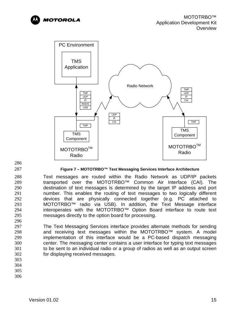
286 Figure 7 – MOTOTRBO™ Text Messaging Services Interface Architecture 287
Text messages are routed within the Radio Network as UDP/IP packets 288 transported over the MOTOTRBO™ Common Air Interface (CAI). The 289 destination of text messages is determined by the target IP address and port 290 number. This enables the routing of text messages to two logically different 291 devices that are physically connected together (e.g. PC attached to 292 MOTOTRBO™ radio via USB). In addition, the Text Message interface 293 interoperates with the MOTOTRBO™ Option Board interface to route text 294 messages directly to the option board for processing. 295 296 The Text Messaging Services interface provides alternate methods for sending 297 and receiving text messages within the MOTOTRBO™ system. A model 298 implementation of this interface would be a PC-based dispatch messaging 299 center. The messaging center contains a user interface for typing text messages 300 to be sent to an individual radio or a group of radios as well as an output screen 301 for displaying received messages. 302 303 304 305 306

MOTOTRBO™ Application Development Kit Overview
Version 01.02 16
For more information about the MOTOTRBO™ Text Messaging Services 307 Interface, please see the following references: 308 309
• MOTOTRBO™ Text Messaging ADK Guide 310 • MOTOTRBO™ Text Messaging Protocol Specification 311 • MOTOTRBO™ Data Services Overview 312
313 For more information about the other interfaces, please refer to the appropriate 314 sections contained within this overview. 315 316
2.7 MOTOTRBO™Automatic Registration Service (ARS) ADK 317 The MOTOTRBO™ subscriber has a number of data applications, such as Text 318 Message, Telemetry and Location, which require the sending of data messages 319 asynchronously to a Subscriber Unit (SU). The ARS provides a common 320 registration service that accepts, stores and distributes subscriber presence 321 information to interested data applications. The ARS can be used by all data 322 applications and helps to reduce the complexity of handling message 323 transmissions, as well as promotes the efficient use of air interface bandwidth. 324 325 The ARS consists of two components, which are the Registration Application in 326 MOTOTRBO™ radio and the ARS Server in customer network. The ARS server 327 is running on a device that is IP capable and is connected to what is called an 328 ARS radio, via USB connection. The ARS Radio is responsible for routing the IP 329 messages sent to and from the ARS Server. The transport layer between the 330 MOTOTRBO™ radio and the ARS Server is UDP/IP. 331 332 The Figure 8 shows an example of the architecture diagram for a simple ARS 333 configuration. Note, in this diagram, a MOTOTRBO™ radio acts as an ARS 334 Radio. 335
336 Figure 8: Example Architecture Diagram of ARS 337
338

MOTOTRBO™ Application Development Kit Overview
Version 01.02 17
For more information on the application of the ARS interface and its protocol, 339 please see the following references: 340 341
• MOTOTRBO™ Automatic Registration Service (ARS) ADK Guide 342 • MOTOTRBO™ Text Messaging ADK Guide 343 • MOTOTRBO™ Location Data ADK Guide 344 • MOTOTRBO™ Telemetry ADK Guide 345 • MOTOTRBO™ Data Services Overview 346
347 For more information about the other interfaces, please refer to the appropriate 348 sections contained within this overview. 349
350
2.8 Presence Notifier 351 The Presence Notifier is used to notify a PC-based backend application, such as 352 for telemetry, LBS, or text messaging, that a MOTOTRBO™ radio has powered 353 on or off and has registered or de-registered with the system. This application 354 allows for efficient bandwidth utilization of the Radio Network – messaging only 355 occurs between the backend application and those MOTOTRBO™ subscribers 356 that are available and that the application is interested in. The Presence Notifier 357 component is for use in digital mode only. 358 359
Radio NetworkUDP
IPCAI
UDPIP
MOTOTRBOTM
Radio
Automatic Registration
Service
Backend Application
SubscriptionNotification
UDPIP
IP Data Pipe
Presence Notifier
360 Figure 9 - Presence Services Architecture 361
362 The MOTOTRBO™ radio contains an Automatic Registration Service (ARS) that 363 sends a registration message to the Presence Notifier within the Radio Network. 364 When the MOTOTRBO™ radio is powered down, a de-registration message is 365 sent. The registration and de-registration messages are sent as UDP/IP packets 366 that are transported over the CAI. The Presence Notifier ultimately receives the 367 UDP/IP packets and processes them for the registration state of each 368 MOTOTRBO™ radio. 369 370
MOTOTRBO™ Application Development Kit Overview
Version 01.02 18
The Presence Notifier tracks the state of each MOTOTRBO™ radio on the Radio 371 Network and reports each radio’s state to each Backend Application. Each 372 backend application must subscribe with the Presence Notifier in order to receive 373 notifications of each MOTOTRBO™ radio of interest. Information between each 374 Backend Application and the Presence Notifier is exchanged as UDP/IP packets. 375 376 For more information about the Presence Notifier, please see the following 377 references: 378 379
• Presence Notifier Application User’s Guide 380 • Presence Notifier-to-Watcher Interface Specification 381 • MOTOTRBO™ Data Services Overview 382
383 For more information about the other interfaces, please refer to the appropriate 384 sections contained within this overview. 385 386
2.9 Data Services 387 Aside from the data application capability of the MOTOTRBO™ product for 388 telemetry, location, and text messaging, the MOTOTRBO™ radios can also be 389 used as a generic UDP/IP “pipe” for the transport of data between multiple IP-390 capable devices. These devices, such as laptop or desktop PCs, must be 391 attached to subscriber units operating within the Radio Network. The Data 392 Services capability is available while the MOTOTRBO™ product is operating in 393 digital mode only. 394 395

MOTOTRBO™ Application Development Kit Overview
Version 01.02 19
MOTOTRBO™ Mobile
UDP/IP over USB
Radio Network
MOTOTRBO™ Mobile UDP/IP
over USB
396 Figure 10 – Data Services Architecture 397
398 The attached PCs are mapped to an IP space that is separate from the 399 MOTOTRBO™ radio IP address range. Therefore, data intended to the attached 400 IP-capable device or the MOTOTRBO™ radio can be routed to the appropriate 401 endpoint. 402 403 For more information about the Data Services capability, please see the following 404 reference: 405 406
• MOTOTRBO™ Data Services Overview 407 408
For more information about the other interfaces, please refer to the appropriate 409 sections contained in this overview. 410
MOTOTRBO™ Application Development Kit Overview
Version 01.02 20
Section 3 411
3.0 Professional Radio Application Developer Program 412 The Professional Radio Application Developer Program now includes MOTOTRBO™ 413 and is comprised of three tiers of membership: 414 415
• Registered User 416 • Licensed Developer 417 • Application Partner / Application Provider 418
419 Each tier of membership brings greater accessibility to program information and 420 development resources. Interested developers must be approved for Licensed 421 Developer or Application Partner status in order to receive items such as: 422 423
• Application Development Kit (ADK) documentation 424 • Technical support, including developer forums and training 425 • Program affiliation media, including partner logo and application directory listing 426 • Motorola channel partner and customer information 427
428 Registered Users have access to general information and resources only. 429 430

MOTOTRBO™ Application Development Kit Overview
Version 01.02 21
431 Figure 11 – Professional Radio Application Developer Program Membership Process Flow 432
433 The capability assessment is based on technical competency, commercial capability, 434 and product portfolio. Characteristics that are considered include: 435 436
• Adequate commercial capability 437 • Expertise in two-way radio communications 438 • Expertise in hardware / software engineering development 439 • Adequate development and test environments 440 • Repeatable development and test processes 441 • Quality Assurance processes 442

MOTOTRBO™ Application Development Kit Overview
Version 01.02 22
Section 4 443
4.0 Service & Support for Application Development 444 The MOTOTRBO™ Application Development Kits (ADKs) are only one component of 445 the service and support for 3rd party developers. The Professional Radio Application 446 Developer Program for MOTOTRBO™ is staffed with full-time engineers whose primary 447 responsibility is to support 3rd party application developers world-wide. Application 448 developers have direct access to Motorola resources to assist in the development and 449 certification of the 3rd party application. 450 451 This service and support includes, but is not limited to, the following items: 452 453
• Technical training on the use and capability of the developer interfaces on the 454 MOTOTRBO™ radio 455
• Application notes and FAQs on relevant MOTOTRBO™ development topics 456 • Technical consultation service during the design and development phases of the 457
3rd party product 458 • Access to a MOTOTRBO™ system test environment with subscribers and 459
infrastructure for 3rd party product verification (where supported by the local 460 business region) 461
462 In order to ensure technical leadership and growth, the capabilities of the 463 MOTOTRBO™ product and the developer interfaces will be continuously improved and 464 enhanced for greater functionality and expansion. As a mechanism to support this 465 process, Motorola will: 466 467
• Assist developers to define feature enhancements 468 • Document and submit change requests for prioritization 469 • Track and oversee defect repair of application interfaces 470
471 Through this process, the MOTOTRBO™ product will be ensured to have: 472 473
• Clear, concise, and accurate developer documentation 474 • Full compliance with published specifications and guides for each application 475
interface 476 • Compatibility audit with older release versions of published specifications 477

MOTOTRBO™ Application Development Kit Overview
Version 01.02 23
Section 5 478
5.0 Further Information and Contact 479 For further information about MOTOTRBO™ and MOTODEV, please visit the following 480 websites: 481 482
• Motorola MOTOTRBO™: http://www.motorola.com/mototrbo 483 • MOTODEV developer network – Professional Radio Application Developer 484
Program: http://developer.motorola.com 485 486 As an alternative, please contact your region’s business development manager for 487 further information on how to develop applications for the MOTOTRBO™ platform. 488 489
• Asia Pacific Region (APAC) 490 o [email protected] 491 492
• Europe, Middle East, and Africa (EMEA) 493 o [email protected] 494 495
• Latin American Countries Region (LACR): 496 o [email protected] 497 498
• North America (NA) 499 o [email protected] 500

MOTOTRBO™ Application Development Kit Overview
Version 01.02 24
Section 6 501
6.0 Appendix: ADK Document Map 502
Document
MO
TOTR
BO
™
Opt
ion
Boa
rd
MO
TOTR
BO
™
Tele
met
ry
MO
TOTR
BO
™
Loca
tion
Dat
a
MO
TOTR
BO
™
Text
Mes
sagi
ng
MO
TOTR
BO
™
XC
MP
-Bas
ed
App
licat
ions
MO
TOTR
BO
™
Non
- IP
A
pplic
atio
ns
MOTOTRBO™ ADK Overview X X X X X X MOTOTRBO™ ARS Protocol Specification X X X MOTOTRBO™ XCMP-Based IP Capable Peripheral ADK Guide X MOTOTRBO™ Option Board ADK Guide X MOTOTRBO™ Option Board PROIS Cross-Reference X
MOTOTRBO™ XCMP / XNL Development Guide X X X MOTOTRBO™ XCMP / XNL Development Specification X X X MOTOTRBO™ Telemetry ADK Guide X MOTOTRBO™ Telemetry Protocol Specification X MOTOTRBO™ Location Data ADK Guide X MOTOTRBO™ LRRP Specification X Motorola Binary XML Encoding Specification X MOTOTRBO™ Text Messaging ADK Guide X MOTOTRBO™ Text Messaging Protocol Specification X Presence Notifier Application User’s Guide X X X Presence Notifier-to-Watcher Interface Specification X X X MOTOTRBO™ Data Services Overview X X X X X X MOTOTRBO™ Third Party Peripheral Cable ADK X X X MOTOTRBO™ Non-IP Capable Peripheral ADK Guide X
MOTOROLA and the Stylized M Logo are registered in the US Patent & Trademark Office. All other product or service names are the property of their respective owners. © Motorola, Inc. 2008. All Rights Reserved. Printed in USA. *6880309T32* 6880309T32