application challenge rtk gps precise rail track surveying railway... · have taken place within...
TRANSCRIPT
Since May 2003, large track renewal projectshave taken place within the West Coast RouteModernization Program (WCRM), de-
manding a major effort from the United Kingdom railindustry. Survey companies play a key role in this pro-gram by providing spatial information for the design-ers of through alignment, tunnels, platforms, drainage,and overhead lines — in other words, for the whole ofthe rail system’s infrastructural assets.
The survey companies support several aspects of re-quired measurement activities during construction— such as monitoring progress of build-up of ballastand to check passing and structural clearances — thatbring the new track and other systems to within their
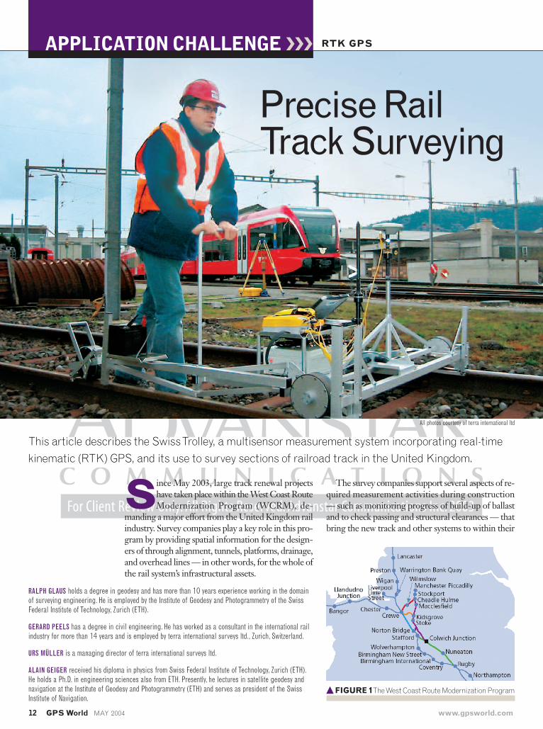
Precise RailTrack Surveying
RTK GPS
This article describes the Swiss Trolley, a multisensor measurement system incorporating real-timekinematic (RTK) GPS, and its use to survey sections of railroad track in the United Kingdom.
RALPH GLAUS holds a degree in geodesy and has more than 10 years experience working in the domainof surveying engineering. He is employed by the Institute of Geodesy and Photogrammetry of the SwissFederal Institute of Technology, Zurich (ETH).
GERARD PEELS has a degree in civil engineering. He has worked as a consultant in the international railindustry for more than 14 years and is employed by terra international surveys ltd., Zurich, Switzerland.
URS MÜLLER is a managing director of terra international surveys ltd.
ALAIN GEIGER received his diploma in physics from Swiss Federal Institute of Technology, Zurich (ETH).He holds a Ph.D. in engineering sciences also from ETH. Presently, he lectures in satellite geodesy andnavigation at the Institute of Geodesy and Photogrammetry (ETH) and serves as president of the SwissInstitute of Navigation.
� FIGURE 1The West Coast Route Modernization Program
12 GPS World MAY 2004 www.gpsworld.com
APPLICATION CHALLENGE
All photos courtesy of terra international ltd
design specifications in the track corridor.
The scope of work for Route Sec-tion 12, covering about 80 kilome-tres (Colwich Junction to CheadleHulme, Figure 1) was the first in a se-ries of track renewal projects that wascrowded with activities coming fromdifferent disciplines and departments.
As the project got under way, sur-vey companies were soon stretched totheir limits using the traditional rela-tive techniques of datum rails and mea-suring offsets, simply because the con-struction program allowed for“floating” roads. These relative mea-surement methods are common prac-tice within UK surveying companies.Offsets are measured and marked upagainst spatial, fixed objects (pegs, nails,permanent ground markers, datumrails). For instance, the six-foot dis-tances between up and down line tracksare measured back to back, or as run-ning edge to running edge of the rail-heads. These measurements aremarked up (with chalk or other moresustainable paints, adding or subtracting both the re-quired horizontal shift and required lift as per design)on that rail, which is intended to stay during the con-
struction efforts of the other track. This works as longas the so-called datum rail is not touched, moved bytamping operations or rail stressing, or in the worst
www.gpsworld.com MAY 2004 GPS World 13
GlossaryBallast:Angularly shaped crushed stone used to support sleepers, timbers, and bearers,both laterally and vertically.
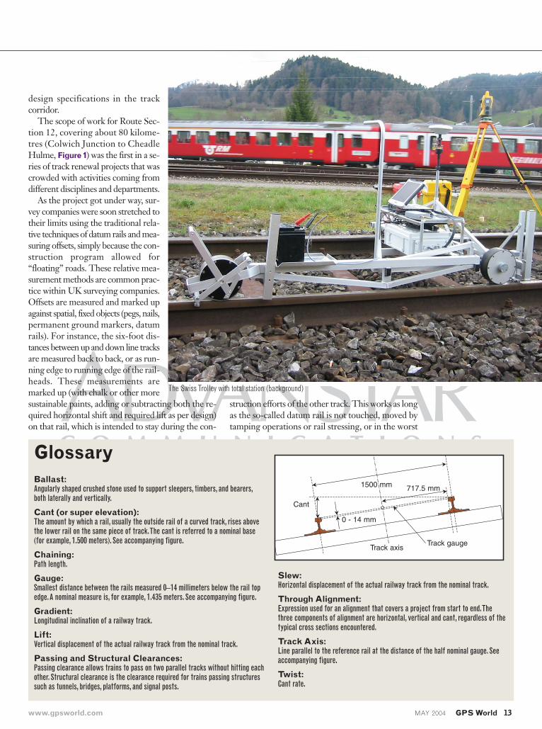
Cant (or super elevation):The amount by which a rail, usually the outside rail of a curved track, rises abovethe lower rail on the same piece of track.The cant is referred to a nominal base(for example, 1.500 meters). See accompanying figure.
Chaining:Path length.
Gauge:Smallest distance between the rails measured 0–14 millimeters below the rail topedge.A nominal measure is, for example, 1.435 meters. See accompanying figure.
Gradient:Longitudinal inclination of a railway track.
Lift:Vertical displacement of the actual railway track from the nominal track.
Passing and Structural Clearances:Passing clearance allows trains to pass on two parallel tracks without hitting eachother. Structural clearance is the clearance required for trains passing structuressuch as tunnels, bridges, platforms, and signal posts.
Slew:Horizontal displacement of the actual railway track from the nominal track.
Through Alignment:Expression used for an alignment that covers a project from start to end.Thethree components of alignment are horizontal, vertical and cant, regardless of thetypical cross sections encountered.
Track Axis:Line parallel to the reference rail at the distance of the half nominal gauge. Seeaccompanying figure.
Twist:Cant rate.
.
Cant
Track gaugeTrack axis
1500 mm 717.5 mm
0 - 14 mm
The Swiss Trolley with total station (background)
case taken out.terra international surveys ltd. of Zurich,
Switzerland was invited by NetworkRail todemonstrate its real-time kinematic (RTK)track-measuring device, called Swiss Trolley,which incorporates optical kinematic total sta-tions and RTK GPS receivers. Soon it becameevident that this absolute way of surveying wasthe solution required to provide accurate, denseand multi-parameter information. This arti-cle features the Swiss Trolley and describes theperformance and limitations of GPS-basedtrack surveying that we encountered.
System DesignThe University of Applied Sciences Burgdorfdeveloped the trolley in collaboration with terrainternational surveys, Switzerland, as part of aproject financed by the Commission for Tech-
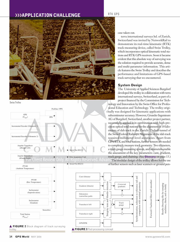
nology and Innovation by the Swiss Office for Profes-sional Education and Technology. The trolley origi-nally was designed for kinematic applications withsubcentimeter accuracy. However, Grunder IngenieureAG of Burgdorf, Switzerland, another project partner,successfully applied it in combination with high-pre-cision optical total stations for the alignment of 18 kilo-meters of slab track in the Zurich-Thalwil-tunnel ofthe Swiss Federal Railways. Alignment of the slab trackrequired millimeter-level accuracies. Apart fromGPS/RTK and total stations, further sensors are neededto completely measure track geometry. Two tiltmeters,a track gauge measuring system, and odometers enablethe assessment of the key parameters: cant, gradient,track gauge, and chaining. (See Glossary on page 13.)
The modular design of the trolley allows for the useof further sensors such as laser scanners or ground pen-
Gradient tiltmeter
Odometers(cen terline path)
Transducer left
GPS/RTK
Cant tiltmeter
Transducer right
Correctedgradients
Trackgauge
� FIGURE 3 Post-processing concept
Incremental Encoder (Odometer 1)
GPS(XAPC)
Incremental Encoder (Odometer 2)
Angular Transducer(dGauge Left)
Angular Transducer(dGauge Right)
PT100(Ambient Temperature)
PT100(Box Temperature)
Inclinometer(Superelevation)
Inclinometer(Gradient)
Sensorbox
Total Station(XPrism)
PPS
PosData / PPS
Serial Port RS232
Data Acquisiton Card
Serial Port RS232
� FIGURE 2 Block diagram of track surveyingtrolley
14 GPS World MAY 2004 www.gpsworld.com
RTK GPS
Swiss Trolley
Inte
grity
test
s an
d bl
unde
r de
tect
ion
Sync
hron
izat
ion,
red
uctio
n to
ref
eren
ce r
ail a
ndco
mpa
riso
n w
ith n
omin
al g
eom
etry
Forw
ard
/ ba
ckw
ard
filte
r an
d sm
ooth
er
Res
ults
(Ste
erin
g fil
e fo
r ta
mpi
ngm
achi
nes,
cha
rts,
and
so
fort
h)
APPLICATION CHALLENGE
etrating radars (GPR). The operation of the trolleyin a stand-alone mode also can provide “path”-“twist”and “path”-“track gauge” charts showing twist and trackgauge as a function of the covered chaining. Stand-alone surveys represent a quick method for track mon-itoring during construction.
Use of SensorsCants and gradients are measured by two fluid dampedinclination sensors. Typical precisions in the staticmode reach about 0.2 mrad. Biases are checked at thebeginning of a survey. This is done by means of in-clination measurements in two faces over a referenceplane.
The track gauge is determined by a function of theangular position of two dragging mechanical scan-ners. Angular transducers measure the deflection ofthe scanners. Calibration is accomplished by com-paring the track gauge reading with a measuringrod reading. The precision of the track gauge mea-suring system reaches about 0.5 millimeters.
Two odometers provide path measurements of theparallel rails, which in turn can generate differentialodometer readings for dead reckoning. The averageof the left and right odometer represents the pathlength of the centerline. Systematic errors may arisefrom an inappropriate scale factor (diameter). Thisparameter can be calibrated by comparing the odome-ter path against the true path length, using total sta-tion data and nominal track data. If the odometer dataare free from slippage, precision can reach a level ofup to 50 ppm. Figure 2 gives an overview of the sen-sors incorporated into the Swiss Trolley system.
Data ProcessingIn order to benefit from the “past” and “future” cor-relations of adjacent measurements, data are post-processed. Kinematic data postprocessing uses a cas-cading filter concept. In contrast to a tightly coupledfilter, we preprocess parameters such as tangential ac-celerations that have minor effect on the final results.This produces a simpler and more stable filter formu-lation. The cascading data processing is divided intothese steps:
� blunder detection / data reduction I� synchronization / data reduction II� filter / smootherFigure 3 illustrates the cascading postprocessing
concept.Blunder Detection, Data Reduction I. Data
processing includes integrity checks and blunder de-tection for each data channel. The reasons for blun-ders are manifold. For example, welding seams onthe rails can cause nuisance accelerations that mainly
affect the tiltmeter readings. The blunder-free dataallow for a first reduction step. As previously men-tioned, tangential accelerations are removed fromthe gradient tiltmeter readings during the prepro-cessing stage.
We can derive accelerations and velocities from thepath measurements by means of fitting polynomialsand the corresponding derivatives. Cubic parabolasprovide good fits with a moderate noise gain. Cen-tripetal accelerations are ignored in the data process-ing, which is considered acceptable because of the lowoperation speed and the large track radii. The angulartransducer data are used for the assessment of the trackgauge and to determine the trolley wobble between therails. Wobble rates are smooth due to the inertia of thetrolley.
Synchronization, Data Reduction II. Synchro-nization of the trolley data with the positioning sensordata only must be done if no pulse per second (PPS)signal is available from the GPS receiver. In contrastto use of a GPS-RTK with PPS, optical total stationdata are not synchronized with the trolley data dur-ing data acquisition.
For the GPS case, the 20 Hz trolley data are down-sampled to the typically used 1 Hz GPS data. A rate of1 Hz is effective to accurately record all track patterns.NMEA sentences sent to the serial port contain theGPS-RTK solutions that use carrier phase integer am-biguity resolution methods. The postprocessing soft-ware allows for a refinement of the geoid undulationsand use of a separate geoid model along a railway track
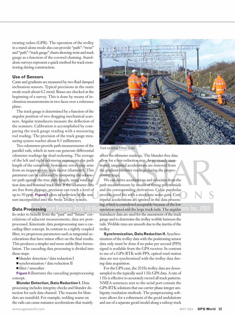
Track surveying trolleys in use
www.gpsworld.com MAY 2004 GPS World 15
being measured. Within the UK project, we refinedthe existing geoid model by comparing the leveling andGPS data along the tracks. In order to compare themeasurements with nominal data, the GPS antennaphase center coordinates have to be reduced to the cen-
terline of the track. The centerline in general does notcorrespond to the actual track axis, because the trackgauge can deviate from its nominal value (for example,1.435 meters). However, reducing to the track axiswould result in a discontinuous curve disturbing thesubsequent filter step. Therefore, corrections due todeviations from the nominal gauge are applied after filtering.
For track renewal projects, a nominal geometry de-scribing the track as a series of analytical functions —straight lines, circles, or clothoids — is available. In thispre-filter step, residual displacements of the nominaltrajectory are evaluated and submitted to the filter.
Filter and Smoothing. An 11-state Kalman filterestimates the track parameters. The filter states includedisplacements from the nominal track, the cant, andthe track gauge. The model assumes a non-acceleratedmotion, incorporates rates for the horizontal andvertical displacements as well as the cant, and intro-duces additional adaptive parameters for the odome-ter scale and the gradient tiltmeter bias. The latter twoparameters can be fixed if they remain constant for asingle survey, which allows a more reliable filter formulation.
For the filter update, seven observations are used pertime batch. The measured horizontal and vertical dis-placements from the nominal track, path, cant, trackgauge, gradient, and odometer path can be submittedto the Kalman filter. The postprocessing allows for fil-tering in forward and backward directions and smooth-ing. This reduces the variance of a forward-only fil-tered solution and minimizes lags caused by aforward-only filtered series.
The filtered data are represented on charts that showrelevant parameters for track renewals as horizontaland vertical displacements (“slew” and “lift”), cant, twistand track gauge. The postprocessing software gener-ates steering files for machine guidance systems of tam-pers. By using the slew and lift parameters, the tamperscan correct the track to the desired position.
If no nominal track data is available, as sometimesoccurs with older railway lines, an absolute trajectoryis estimated. The filter states in this case include po-sition, velocity, azimuth, curvature, cant, gradient, trackgauge, odometer scale, and gradient tiltmeter bias. Thefiltered data are a basis for track regressions in whichanalytical functions have to be fitted through the trajectory.
The typical work flow contains several track runswith overlapping sections. To improve accuracy, a trackis normally surveyed in both directions. A further toolwithin the postprocessing software allows for mergingdata from all runs and takes into consideration the even-tual remaining biases. The merge process takes into
RTK GPS
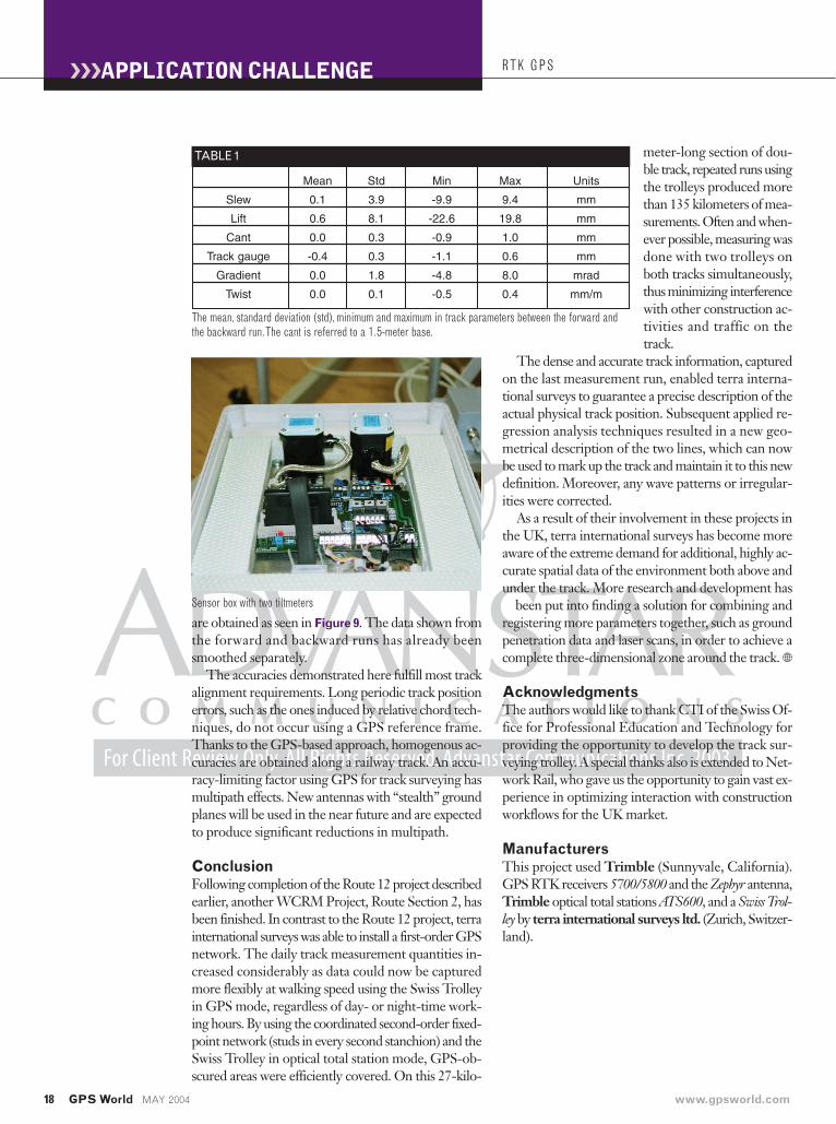
� FIGURE 6 Lift of a forward and a backward run
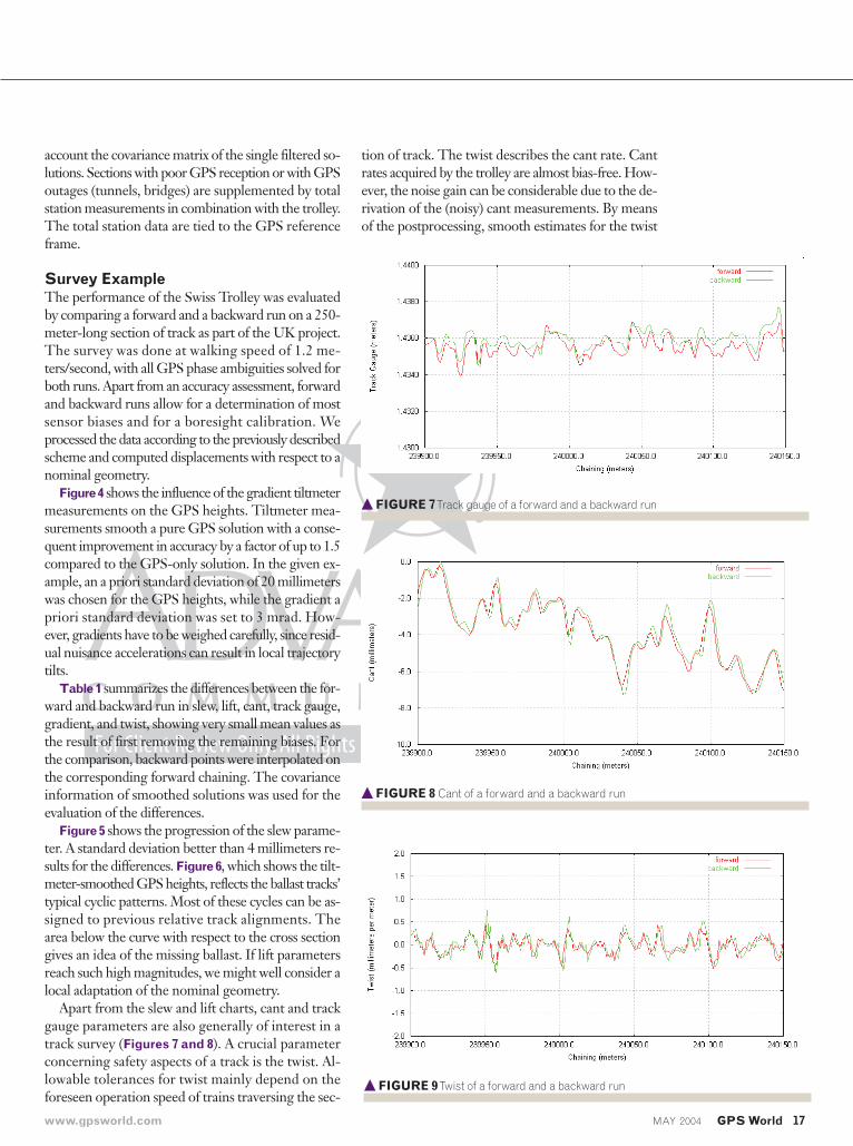
� FIGURE 5 Slew of a forward and a backward run
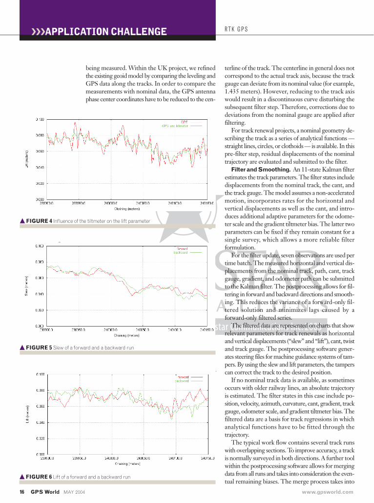
� FIGURE 4 Influence of the tiltmeter on the lift parameter
16 GPS World MAY 2004 www.gpsworld.com
APPLICATION CHALLENGE
account the covariance matrix of the single filtered so-lutions. Sections with poor GPS reception or with GPSoutages (tunnels, bridges) are supplemented by totalstation measurements in combination with the trolley.The total station data are tied to the GPS referenceframe.
Survey ExampleThe performance of the Swiss Trolley was evaluatedby comparing a forward and a backward run on a 250-meter-long section of track as part of the UK project.The survey was done at walking speed of 1.2 me-ters/second, with all GPS phase ambiguities solved forboth runs. Apart from an accuracy assessment, forwardand backward runs allow for a determination of mostsensor biases and for a boresight calibration. Weprocessed the data according to the previously describedscheme and computed displacements with respect to anominal geometry.
Figure 4 shows the influence of the gradient tiltmetermeasurements on the GPS heights. Tiltmeter mea-surements smooth a pure GPS solution with a conse-quent improvement in accuracy by a factor of up to 1.5compared to the GPS-only solution. In the given ex-ample, an a priori standard deviation of 20 millimeterswas chosen for the GPS heights, while the gradient apriori standard deviation was set to 3 mrad. How-ever, gradients have to be weighed carefully, since resid-ual nuisance accelerations can result in local trajectorytilts.
Table 1 summarizes the differences between the for-ward and backward run in slew, lift, cant, track gauge,gradient, and twist, showing very small mean values asthe result of first removing the remaining biases. Forthe comparison, backward points were interpolated onthe corresponding forward chaining. The covarianceinformation of smoothed solutions was used for theevaluation of the differences.
Figure 5 shows the progression of the slew parame-ter. A standard deviation better than 4 millimeters re-sults for the differences. Figure 6, which shows the tilt-meter-smoothed GPS heights, reflects the ballast tracks’typical cyclic patterns. Most of these cycles can be as-signed to previous relative track alignments. Thearea below the curve with respect to the cross sectiongives an idea of the missing ballast. If lift parametersreach such high magnitudes, we might well consider alocal adaptation of the nominal geometry.
Apart from the slew and lift charts, cant and trackgauge parameters are also generally of interest in atrack survey (Figures 7 and 8). A crucial parameterconcerning safety aspects of a track is the twist. Al-lowable tolerances for twist mainly depend on theforeseen operation speed of trains traversing the sec-
tion of track. The twist describes the cant rate. Cantrates acquired by the trolley are almost bias-free. How-ever, the noise gain can be considerable due to the de-rivation of the (noisy) cant measurements. By meansof the postprocessing, smooth estimates for the twist
� FIGURE 7Track gauge of a forward and a backward run
� FIGURE 8 Cant of a forward and a backward run
� FIGURE 9Twist of a forward and a backward run
www.gpsworld.com MAY 2004 GPS World 17
18 GPS World MAY 2004 www.gpsworld.com
are obtained as seen in Figure 9. The data shown fromthe forward and backward runs has already beensmoothed separately.
The accuracies demonstrated here fulfill most trackalignment requirements. Long periodic track positionerrors, such as the ones induced by relative chord tech-niques, do not occur using a GPS reference frame.Thanks to the GPS-based approach, homogenous ac-curacies are obtained along a railway track. An accu-racy-limiting factor using GPS for track surveying hasmultipath effects. New antennas with “stealth” groundplanes will be used in the near future and are expectedto produce significant reductions in multipath.
ConclusionFollowing completion of the Route 12 project describedearlier, another WCRM Project, Route Section 2, hasbeen finished. In contrast to the Route 12 project, terrainternational surveys was able to install a first-order GPSnetwork. The daily track measurement quantities in-creased considerably as data could now be capturedmore flexibly at walking speed using the Swiss Trolleyin GPS mode, regardless of day- or night-time work-ing hours. By using the coordinated second-order fixed-point network (studs in every second stanchion) and theSwiss Trolley in optical total station mode, GPS-ob-scured areas were efficiently covered. On this 27-kilo-
meter-long section of dou-ble track, repeated runs usingthe trolleys produced morethan 135 kilometers of mea-surements. Often and when-ever possible, measuring wasdone with two trolleys onboth tracks simultaneously,thus minimizing interferencewith other construction ac-tivities and traffic on thetrack.
The dense and accurate track information, capturedon the last measurement run, enabled terra interna-tional surveys to guarantee a precise description of theactual physical track position. Subsequent applied re-gression analysis techniques resulted in a new geo-metrical description of the two lines, which can nowbe used to mark up the track and maintain it to this newdefinition. Moreover, any wave patterns or irregular-ities were corrected.
As a result of their involvement in these projects inthe UK, terra international surveys has become moreaware of the extreme demand for additional, highly ac-curate spatial data of the environment both above andunder the track. More research and development has
been put into finding a solution for combining andregistering more parameters together, such as groundpenetration data and laser scans, in order to achieve acomplete three-dimensional zone around the track. �
AcknowledgmentsThe authors would like to thank CTI of the Swiss Of-fice for Professional Education and Technology forproviding the opportunity to develop the track sur-veying trolley. A special thanks also is extended to Net-work Rail, who gave us the opportunity to gain vast ex-perience in optimizing interaction with constructionworkflows for the UK market.
ManufacturersThis project used Trimble (Sunnyvale, California).GPS RTK receivers 5700/5800 and the Zephyr antenna,Trimble optical total stations ATS600, and a Swiss Trol-ley by terra international surveys ltd. (Zurich, Switzer-land).
RTK GPS
Sensor box with two tiltmeters
Mean Std Min Max Units
Slew 0.1 3.9 -9.9 9.4 mm
Lift 0.6 8.1 -22.6 19.8 mm
Cant 0.0 0.3 -0.9 1.0 mm
Track gauge -0.4 0.3 -1.1 0.6 mm
Gradient 0.0 1.8 -4.8 8.0 mrad
Twist 0.0 0.1 -0.5 0.4 mm/m
TABLE 1
The mean, standard deviation (std), minimum and maximum in track parameters between the forward andthe backward run.The cant is referred to a 1.5-meter base.
APPLICATION CHALLENGE