applianx gateway user guide -...
TRANSCRIPT

ApplianX IP Gateway User Guide
Version 2.3.7 – 21/09/2016

2 of 75
1.0 GETTING STARTED............................................................... 5
1.1 How to use this guide ....................................................................................... 5
1.2 Prerequisites ..................................................................................................... 5
1.3 LEDs ................................................................................................................... 5
1.4 Setting up the Gateway ..................................................................................... 5
1.5 Logging in to the web interface ........................................................................ 5
1.6 First time use ..................................................................................................... 6
1.7 The Setup Wizard ............................................................................................ 10
1.8 The main menu ................................................................................................ 11
1.9 The Overview page .......................................................................................... 13
1.10 Networking ..................................................................................................... 13 1.10.1 Network settings via the web interface ...................................................... 13 1.10.2 Network settings via USB flash memory .................................................... 15
2.0 CONFIGURING THE GATEWAY .......................................... 15
2.1 Gateway configurations .................................................................................. 15 2.1.1 Configuration pages .................................................................................... 16 2.1.2 General ....................................................................................................... 16 2.1.3 Trunks ......................................................................................................... 19
2.1.3.1 Editing the SIP trunk ............................................................................. 19 2.1.3.2 Editing a TDM Trunk ............................................................................. 20 2.1.3.3 Editing a TDM Trunk Protocol ............................................................... 21
2.1.4 Endpoints .................................................................................................... 23 2.1.5 Groups ........................................................................................................ 26
2.1.5.1 Adding or editing a group ...................................................................... 26 2.1.6 Routes......................................................................................................... 27
2.1.6.1 Routes and Local Survivability .............................................................. 29 2.1.7 Clocking ...................................................................................................... 32 2.1.8 SIP .............................................................................................................. 33 2.1.9 Codecs ........................................................................................................ 38 2.1.10 Survivability ............................................................................................... 39 2.1.11 Test ........................................................................................................... 40
2.2 Backing up and restoring ............................................................................... 41 2.2.1 System configuration ................................................................................... 42
2.2.1.1 Saving and restoring the system configuration via USB port ................. 42 2.2.2 Gateway Configurations .............................................................................. 43
2.3 Factory Reset................................................................................................... 43 2.3.1 Gateway ...................................................................................................... 43 2.3.2 Gateway MkII .............................................................................................. 43

3 of 75
2.4 Shutdown ......................................................................................................... 44
3.0 ADDITIONAL INFORMATION .............................................. 45
3.1 Routing Overview ............................................................................................ 45
3.2 X.509 Certificates ............................................................................................ 45
3.3 Creating X.509 certificates using OpenSSL................................................... 46
3.4 HTTPS .............................................................................................................. 51
3.5 Secure SIP over TLS ....................................................................................... 51
3.6 Software Updates ............................................................................................ 54 3.6.1 Getting update images ................................................................................ 54 3.6.2 Getting ax-img-tool ...................................................................................... 55 3.6.3 Validating update images ............................................................................ 55 3.6.4 To apply an update image using HTTP ....................................................... 55 3.6.5 To apply an update using USB .................................................................... 58
3.7 Local Survivability ........................................................................................... 60 3.7.1 Overview ..................................................................................................... 60 3.7.2 Features not supported ............................................................................... 61 3.7.3 Enabling local survivability ........................................................................... 61 3.7.4 Central PBX responsiveness ....................................................................... 61 3.7.5 Switching to active mode ............................................................................. 61 3.7.6 Registrar ..................................................................................................... 62 3.7.7 Configuring SIP devices .............................................................................. 63 3.7.8 Managing user aliases ................................................................................ 63 3.7.9 View aliases ................................................................................................ 65 3.7.10 Overview page .......................................................................................... 66
3.8 DDI barring ....................................................................................................... 67
3.9 DNS Caching ................................................................................................... 67
4.0 DIAGNOSTICS ..................................................................... 69
4.1 Remote Logging .............................................................................................. 69
4.2 Diagnostic Log ................................................................................................ 70
5.0 TROUBLESHOOTING .......................................................... 70
5.1 Logging into the remote interface .................................................................. 70 5.1.1 I can’t get access to the Gateway web interface .......................................... 70 5.1.2 I log on but the overview screen has warnings at the top ............................ 71
5.2 MAKING CALLS THROUGH THE GATEWAY ..................... 71 5.2.1 I can’t make a call from the TDM side of the Gateway to an IP client. ......... 71
5.3 Configuring the Gateway ................................................................................ 73

4 of 75
5.3.1 I have made changes to the configuration but they don’t seem to have any effect. ................................................................................................................... 73 5.3.2 I used the wizard to create an initial configuration but I have an error saying that there is no active configuration. ..................................................................... 73
5.4 Local Survivability ........................................................................................... 73 5.4.1When the central PBX is back online, phones with the same number but situated at other sites stop working. ..................................................................... 73
6.0 GLOSSARY .......................................................................... 74

5 of 75
1.0 Getting started
1.1 How to use this guide
The ApplianX IP Gateway (hereafter referred to as the Gateway) has been designed for ease of set up. However we recommend that new users read sections 1 - 3 of this guide before trying to set up a Gateway for the first time. Sections 2 and 3 are a reference for those that have used the Gateway before while sections 4 and 5, Diagnostics and Troubleshooting, should only be needed if problems have been encountered.
1.2 Prerequisites
The Gateway is configured via a web interface. To use this, a device with a web browser must be connected to the Gateway using appropriate network cabling and switches. Note that the network ports of the Gateway must be connected to Ethernet switches as opposed to Ethernet hubs.
1.3 LEDs
There are a number of LEDs on the front of the Gateway which help during the installation and running of the Gateway:
Error – This red LED indicates a serious error. If this is lit at any time other when the Gateway is starting up then a serious error has occurred and a restart of the Gateway will be required.
Warning – This red LED indicates that the Gateway has an error condition that should be resolved. Log into the Gateway via the web interface to identify the nature of the problem.
Activity – This blue LED will flash when the Gateway is starting up and also when it is processing calls.
Ready – This Green LED is lit when the Gateway is ready for operation.
Initialising – This Orange LED indicates that the Gateway is starting. Note that user interaction via the web interface may be needed in order to progress to Ready.
1.4 Setting up the Gateway
There are a number of steps that need to be carried out before the Gateway can be used to service calls. The Setup Wizard is designed to create a basic configuration.
1.5 Logging in to the web interface
The Gateway should be powered up with LAN cables connecting the VoIP traffic port and the Admin port to the network. For versions 2.1.0 and later the Gateway administrative interface will have the static IP address 192.168.1.100. For earlier versions please consult earlier versions of the documentation.

6 of 75
Connect a PC directly to the Gateway admin port with an Ethernet cable. Set the PC to have the static IP address 192.168.1.1 with a net mask of 255.255.255.0. By typing 192.168.1.100 into the web browser the Gateway administration interface should be accessible. Change the static IP address to something suitable for the network it will be used in. Once set up in a network the Gateway will be accessible via the ApplianX Search Tool. This is available from the Aculab website. Once installed, start ApplianX Search Tool from the Start menu. The ApplianX Search Tool will search the local network for ApplianX products and report the IP address of any products it finds (see Figure 1-0 below).
Figure 1-0 The ApplianX Search Tool
A context menu is presented when right clicking on a listed Gateway device. From the context menu it is possible to direct your default browser to automatically navigate to your Gateway web interface login page. Please see the troubleshooting section if you cannot gain access to the Gateway web interface.
1.6 First time use
The Gateway web interface uses HTTPS to protect your session. The default certificate will trigger a security warning on modern browsers. Although the browser will indicate that it doesn't trust the source of the certificate, the session will be encrypted. It is possible to replace the supplied certificate with your own. NOTE: HTTPS is subject to export controls and may not be available in your territory. In Internet Explorer 7 and 8:

7 of 75
Figure 1-2 Internet Explorer 7 and 8 security warning
Click on “Continue to this website” to proceed. In Firefox 3.5:
Figure 1-3 Firefox 3.5 security warning
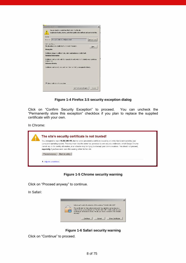
Expand the “I Understand the Risks” section and click “Add Exception...”.
8 of 75
Figure 1-4 Firefox 3.5 security exception dialog
Click on “Confirm Security Exception” to proceed. You can uncheck the “Permanently store this exception” checkbox if you plan to replace the supplied certificate with your own. In Chrome:
Figure 1-5 Chrome security warning
Click on “Proceed anyway” to continue. In Safari:
Figure 1-6 Safari security warning
Click on “Continue” to proceed.

9 of 75
On first use the Gateway web interface will display the page as in Figure 1-7 Configuring initial administrative user. The user is required to provide a user name and password for an administrative user for the Gateway. Enter a user name, password and confirm the password. The user name and password cannot be left blank. Click Submit to create the account and login. Note: It is important to remember the user name and password that you configure. If you forget, you will need to perform a factory reset to gain access to the Gateway. See the Factory Reset section below.
Figure 1-7 Configuring initial administrative user
10 of 75
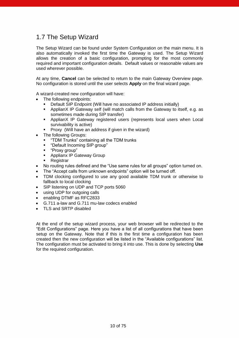
1.7 The Setup Wizard
The Setup Wizard can be found under System Configuration on the main menu. It is also automatically invoked the first time the Gateway is used. The Setup Wizard allows the creation of a basic configuration, prompting for the most commonly required and important configuration details. Default values or reasonable values are used wherever possible. At any time, Cancel can be selected to return to the main Gateway Overview page. No configuration is stored until the user selects Apply on the final wizard page. A wizard-created new configuration will have:
The following endpoints: Default SIP Endpoint (Will have no associated IP address initially) ApplianX IP Gateway self (will match calls from the Gateway to itself, e.g. as
sometimes made during SIP transfer) ApplianX IP Gateway registered users (represents local users when Local
survivability is active) Proxy (Will have an address if given in the wizard)
The following Groups: “TDM Trunks” containing all the TDM trunks “Default Incoming SIP group” “Proxy group” Applianx IP Gateway Group Registrar
No routing rules defined and the “Use same rules for all groups” option turned on.
The “Accept calls from unknown endpoints” option will be turned off.
TDM clocking configured to use any good available TDM trunk or otherwise to fallback to local clocking
SIP listening on UDP and TCP ports 5060
using UDP for outgoing calls
enabling DTMF as RFC2833
G.711 a-law and G.711 mu-law codecs enabled
TLS and SRTP disabled At the end of the setup wizard process, your web browser will be redirected to the “Edit Configurations” page. Here you have a list of all configurations that have been setup on the Gateway. Note that if this is the first time a configuration has been created then the new configuration will be listed in the “Available configurations” list. The configuration must be activated to bring it into use. This is done by selecting Use for the required configuration.

11 of 75
1.8 The main menu
On the left of the screen at all times, apart from when the wizard is running, you will be able to access all the configuration and status pages.
Status o Overview – A page with some basic call statistics and notification of any
issues requiring action from the administrator. o Alarms – This page will display any Layer 1 or Layer 2 alarms on the
TDM trunks. It will also allow the masking of these alarms. o Calls – A graphical display of all the call activity on the Gateway. o Call Log - A recent history of calls that the Gateway has attempted to
route. This page can be very useful for diagnosing issues during the set up phase for the Gateway.
o Trunk Status – This has detailed information on the SIP and TDM trunks
System Configuration o Global Configuration – This allows the box to be named
System Time – This allows the setting of the clock to local time and NTP configuration.
HTTPS Configuration – This allows you to view information about the HTTPS certificate currently in use and replace it if required. Only available if your Gateway has encryption.
SIP TLS Configuration – This allows you to configure TLS certificates. Only available if your Gateway has encryption.
Software Updates – From this page a check can be made for software updates.
System Users – This allows the addition of new administrators to the Gateway and the setting of their privileges.
Backup and Restore – This allows configurations to be saved and restored.
o Networking – This allows the user to choose static IP addresses or DHCP mode
Static DNS – Manual input of static DNS address that avoids DNS request
DNS status – Shows DNS server status and DNS cache contents. It’s possible to flush the DNS cache from here.
SNMP – This allows the configuration of the SNMP settings. From here you can enter the IP address of the host you wish to send traps to and enable them. Also here you can turn on the traps for the disconnecting of the Ethernet ports. Similar options are available for the TDM ports through the TDM configuration options.
o Setup Wizard – This allows the setup wizard to be run to create a skeleton configuration
o SIP Credentials – This allows the configuration of details to allow the Gateway to respond appropriately when challenged for authorisation information.

12 of 75
Gateway Configuration o Alias Registrar – View SIP user aliases for Local survivability and
any current registrations against them.
Manage Aliases – Upload, backup and clear SIP users. o DDI Barring – Upload, backup and clear barred DDIs. o Edit Configurations – This takes you to the main configuration
overview where different Configurations can be selected and edited. Aspects of operation such as Codecs, SIP behaviour, Routing Rules and Groups can be grouped together in Configurations that can be switched as a single entity.
o Interoperability – Configuration of the system SIP stack. For use under Aculab Technical Support supervision.
o Cause Mappings – Here the clearing causes between SIP, QSIG and DPNSS can be changed from their default values.
Diagnostics o Remote Logging – This allows the administrator to direct the syslog
output from the Gateway to an external syslog client or the ApplianX Trace Tool. This is for advanced users and support teams.
o Network Diagnostics – Lets you ping from the Admin or Signalling Ethernet ports to let you verify that the network interfaces can access other terminals on the network.
o Watchdog Status – This reveals the status of the “watchdogs” running on the Gateway. They are here to look for any elements that have failed or are reporting problems. This is for advanced users and support teams.
o Restart – This is used to “reboot” the Gateway. The Gateway MkII will also offer a shutdown feature. Note that rebooting will cause contact through the web interface to be lost.
o Diagnostic Log – This provides some trace of Gateway activity and can be used for debugging purposes.
Resource – Some internal resource statistics.
Switch – Some channel and switch statistics. o Endpoint Status – This page lists the status of those IP endpoints
that have been configured for monitoring o About – This gives build information on the Gateway. o Hardware – This displays the version and status of the hardware used
in the Gateway.
Account o Log Out – This allows the current user to log out of the Gateway
administration screens. o Change Password – This allows the current administration user to
change their password.
13 of 75
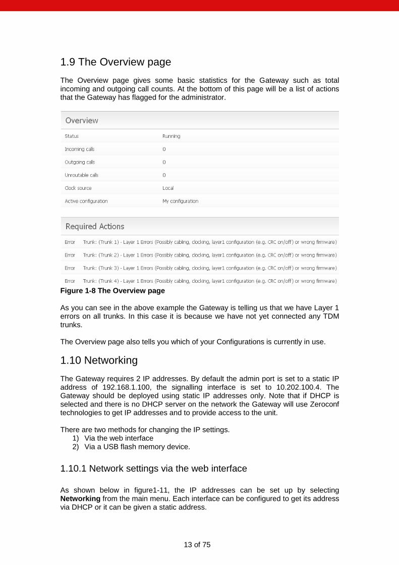
1.9 The Overview page
The Overview page gives some basic statistics for the Gateway such as total incoming and outgoing call counts. At the bottom of this page will be a list of actions that the Gateway has flagged for the administrator.
Figure 1-8 The Overview page As you can see in the above example the Gateway is telling us that we have Layer 1 errors on all trunks. In this case it is because we have not yet connected any TDM trunks. The Overview page also tells you which of your Configurations is currently in use.
1.10 Networking
The Gateway requires 2 IP addresses. By default the admin port is set to a static IP address of 192.168.1.100, the signalling interface is set to 10.202.100.4. The Gateway should be deployed using static IP addresses only. Note that if DHCP is selected and there is no DHCP server on the network the Gateway will use Zeroconf technologies to get IP addresses and to provide access to the unit. There are two methods for changing the IP settings.
1) Via the web interface 2) Via a USB flash memory device.
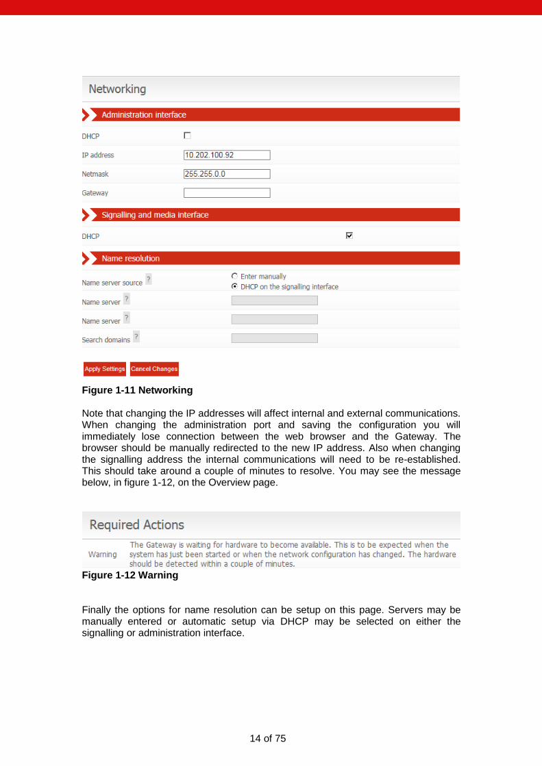
1.10.1 Network settings via the web interface
As shown below in figure1-11, the IP addresses can be set up by selecting Networking from the main menu. Each interface can be configured to get its address via DHCP or it can be given a static address.
14 of 75
Figure 1-11 Networking Note that changing the IP addresses will affect internal and external communications. When changing the administration port and saving the configuration you will immediately lose connection between the web browser and the Gateway. The browser should be manually redirected to the new IP address. Also when changing the signalling address the internal communications will need to be re-established. This should take around a couple of minutes to resolve. You may see the message below, in figure 1-12, on the Overview page.
Figure 1-12 Warning Finally the options for name resolution can be setup on this page. Servers may be manually entered or automatic setup via DHCP may be selected on either the signalling or administration interface.

15 of 75
1.10.2 Network settings via USB flash memory
On a USB flash disk device, at root level, create a directory named applianx_net.
This directory must contain two text files. One file, named admin, will contain IP
address information for the Admin port that allows web browser access to the
Gateway. A second file, named signalling, will contain the IP address information
for the Signalling port that allows SIP calls to be made to and from the Gateway. The
files admin and signalling must not have file extensions.
To specify static IP address information the files must contain the following format;
[config]
ip = 10.202.165.169
netmask = 255.255.0.0
gateway = 10.202.100.254
To specify IP addresses to be set via DHCP the files must contain the following format;
[config]
dhcp = 1
At boot up, if the Gateway detects a USB flash disk device, then it will search the USB disk for the files mentioned above. If found the information inside them will be used to set the IP address information for the Gateway. Note: Using this method takes a few minutes longer for the Gateway to come into service.
2.0 Configuring the Gateway
2.1 Gateway configurations
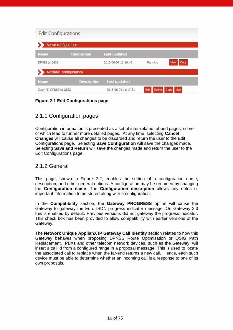
All Gateway configurations are managed from the Figure 2-1 Edit Configurations page (see Figure 2-1 below). The currently active configuration is listed first. This may not be directly edited, but may be examined by selecting View. To modify the active configuration, it is first necessary to click Copy next to the active configuration entry. When you are happy with edits made to a new or copied configuration you can select this to be the active configuration by selecting the Use button on the right of the configuration.
16 of 75
Figure 2-1 Edit Configurations page
2.1.1 Configuration pages
Configuration information is presented as a set of inter-related tabbed pages, some of which lead to further more detailed pages. At any time, selecting Cancel Changes will cause all changes to be discarded and return the user to the Edit Configurations page. Selecting Save Configuration will save the changes made. Selecting Save and Return will save the changes made and return the user to the Edit Configurations page.
2.1.2 General
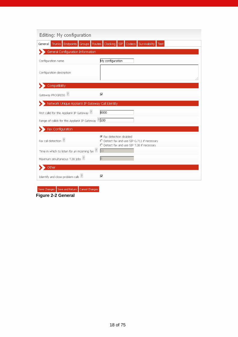
This page, shown in Figure 2-2, enables the setting of a configuration name, description, and other general options. A configuration may be renamed by changing the Configuration name. The Configuration description allows any notes or important information to be stored along with a configuration. In the Compatibility section, the Gateway PROGRESS option will cause the Gateway to gateway the Euro ISDN progress indicator message. On Gateway 2.3 this is enabled by default. Previous versions did not gateway the progress indicator. This check box has been provided to allow compatibility with earlier versions of the Gateway. The Network Unique ApplianX IP Gateway Call Identity section relates to how this Gateway behaves when proposing DPNSS Route Optimisation or QSIG Path Replacement. PBXs and other telecom network devices, such as the Gateway, will insert a call id from a configured range in a proposal message. This is used to locate the associated call to replace when the far-end returns a new call. Hence, each such device must be able to determine whether an incoming call is a response to one of its own proposals.

17 of 75
The Fax Configuration section controls how the Gateway handles incoming calls from a fax machine. If either of the two fax detection modes is enabled, after the call is connected the Gateway will listen for fax CNG tone for the configured time period. The time is typically limited to avoid false positives during a call. If CNG tone is detected, any Gateway active echo cancellation will be disabled. If either call leg is over SIP and “Detect fax and use SIP G.711 if necessary” option is selected, SDP renegotiation will also be performed to ensure only G.711 codecs are selected. If the “Detect fax and use SIP T.38 if necessary” option is selected, the SIP call leg will be renegotiated to use T.38. If the SIP endpoint rejects the T.38 renegotiation, then the Gateway will attempt to negotiate G.711 as a fallback. Fax is not supported over SIP to SIP calls. The “Maximum simultaneous T.38 jobs” can be used to limit the maximum number of T.38 calls the Gateway can process. Incoming T.38 SIP calls, or SIP calls that are renegotiated to T.38 by the SIP endpoint, will always be accepted (as long as the maximum simultaneous T.38 jobs limit is not exceeded). The fax call detection type maybe overridden on a per-routing rule basis. When enabled the “Identify and close problem calls” option assigns a four minute timer to each incoming or outgoing call. Should a call not be answered or become unresponsive then the ApplianX will close the relevant call upon timer expiry.
18 of 75
Figure 2-2 General

19 of 75
2.1.3 Trunks
All available trunks are listed on the Trunks page as in Figure 2- 3 Trunks page. The SIP trunk and TDM trunks are listed separately. Settings for an individual trunk can be changed by selecting Edit next to the trunk.
Figure 2- 3 Trunks page
2.1.3.1 Editing the SIP trunk
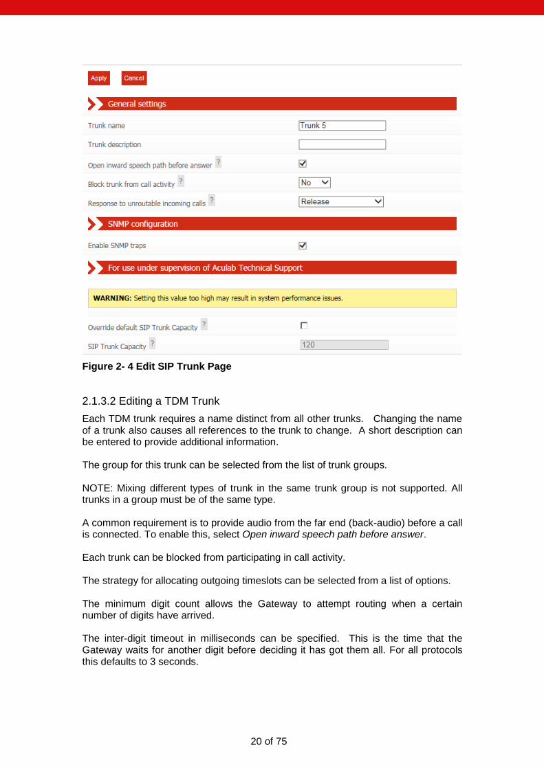
The SIP trunk requires a name distinct from all other trunks. Changing the name of a trunk also causes all references to the trunk to change. A short description can be entered to provide additional information. A common requirement is to provide audio from the far end (back-audio) before a call is connected. To enable this, select Open inward speech path before answer. The SIP trunk can be blocked from participating in call activity. The strategy for dealing with calls that cannot be routed can be selected. For example, connect with a tone; alert with a tone; progress with a tone; setup with a tone or no response. To enable SNMP traps for the signalling network interface, select the appropriately labelled tick box. The SIP trunk SNMP traps sent by the Gateway relate to local branch survivability (see 3.7 Local Survivability): traps are sent when the local survivability function switches between active mode and passive mode.
20 of 75
Figure 2- 4 Edit SIP Trunk Page
2.1.3.2 Editing a TDM Trunk
Each TDM trunk requires a name distinct from all other trunks. Changing the name of a trunk also causes all references to the trunk to change. A short description can be entered to provide additional information. The group for this trunk can be selected from the list of trunk groups. NOTE: Mixing different types of trunk in the same trunk group is not supported. All trunks in a group must be of the same type. A common requirement is to provide audio from the far end (back-audio) before a call is connected. To enable this, select Open inward speech path before answer. Each trunk can be blocked from participating in call activity. The strategy for allocating outgoing timeslots can be selected from a list of options. The minimum digit count allows the Gateway to attempt routing when a certain number of digits have arrived. The inter-digit timeout in milliseconds can be specified. This is the time that the Gateway waits for another digit before deciding it has got them all. For all protocols this defaults to 3 seconds.
21 of 75
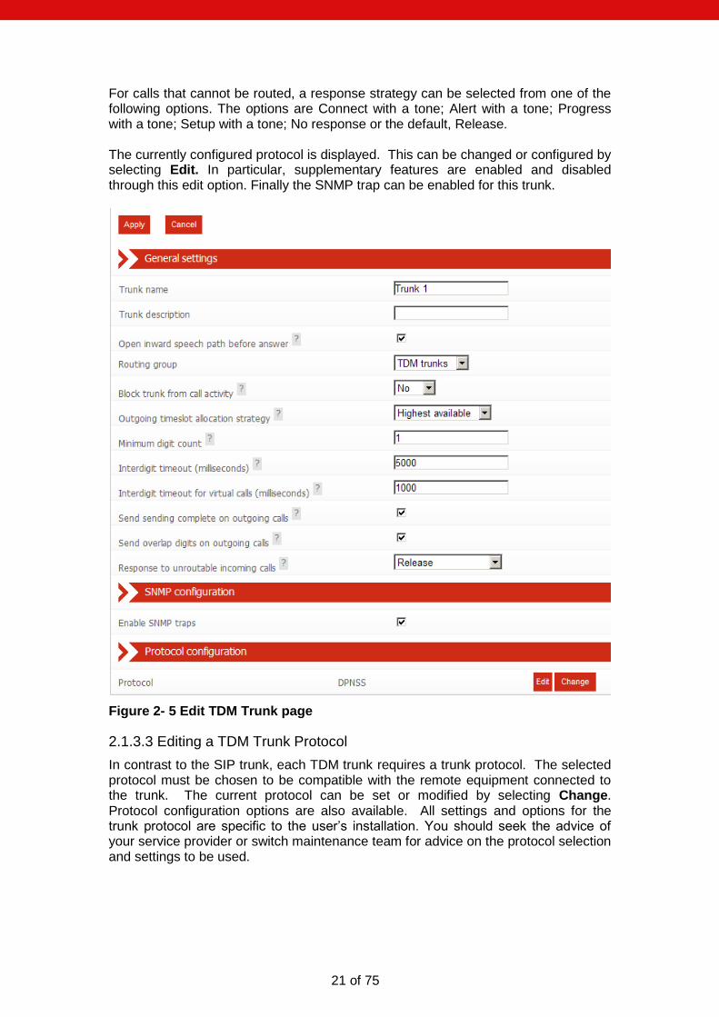
For calls that cannot be routed, a response strategy can be selected from one of the following options. The options are Connect with a tone; Alert with a tone; Progress with a tone; Setup with a tone; No response or the default, Release. The currently configured protocol is displayed. This can be changed or configured by selecting Edit. In particular, supplementary features are enabled and disabled through this edit option. Finally the SNMP trap can be enabled for this trunk.
Figure 2- 5 Edit TDM Trunk page
2.1.3.3 Editing a TDM Trunk Protocol
In contrast to the SIP trunk, each TDM trunk requires a trunk protocol. The selected protocol must be chosen to be compatible with the remote equipment connected to the trunk. The current protocol can be set or modified by selecting Change. Protocol configuration options are also available. All settings and options for the trunk protocol are specific to the user’s installation. You should seek the advice of your service provider or switch maintenance team for advice on the protocol selection and settings to be used.

22 of 75
Figure 2-6 Editing TDM Trunk Protocol
23 of 75
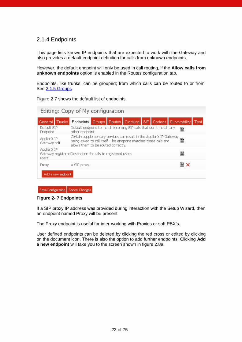
2.1.4 Endpoints
This page lists known IP endpoints that are expected to work with the Gateway and also provides a default endpoint definition for calls from unknown endpoints. However, the default endpoint will only be used in call routing, if the Allow calls from unknown endpoints option is enabled in the Routes configuration tab. Endpoints, like trunks, can be grouped; from which calls can be routed to or from. See 2.1.5 Groups Figure 2-7 shows the default list of endpoints.
Figure 2- 7 Endpoints If a SIP proxy IP address was provided during interaction with the Setup Wizard, then an endpoint named Proxy will be present The Proxy endpoint is useful for inter-working with Proxies or soft PBX’s. User defined endpoints can be deleted by clicking the red cross or edited by clicking on the document icon. There is also the option to add further endpoints. Clicking Add a new endpoint will take you to the screen shown in figure 2.8a.
24 of 75
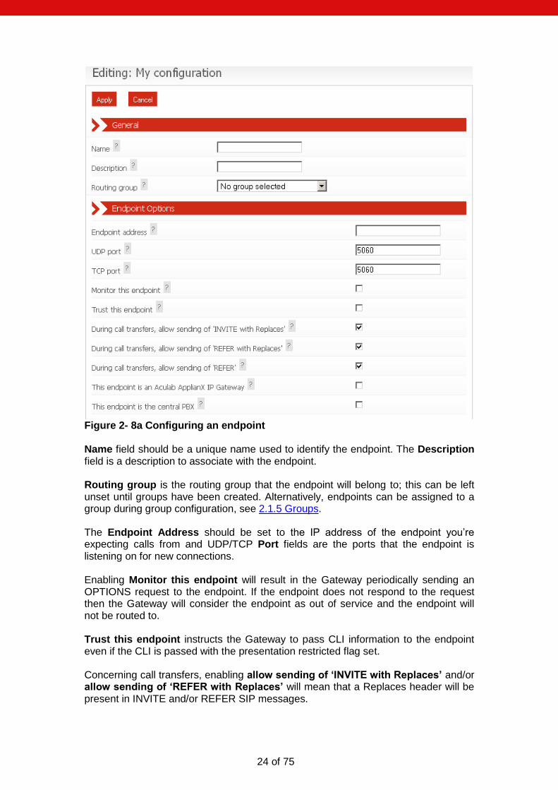
Figure 2- 8a Configuring an endpoint Name field should be a unique name used to identify the endpoint. The Description field is a description to associate with the endpoint. Routing group is the routing group that the endpoint will belong to; this can be left unset until groups have been created. Alternatively, endpoints can be assigned to a group during group configuration, see 2.1.5 Groups. The Endpoint Address should be set to the IP address of the endpoint you’re expecting calls from and UDP/TCP Port fields are the ports that the endpoint is listening on for new connections. Enabling Monitor this endpoint will result in the Gateway periodically sending an OPTIONS request to the endpoint. If the endpoint does not respond to the request then the Gateway will consider the endpoint as out of service and the endpoint will not be routed to. Trust this endpoint instructs the Gateway to pass CLI information to the endpoint even if the CLI is passed with the presentation restricted flag set. Concerning call transfers, enabling allow sending of ‘INVITE with Replaces’ and/or allow sending of ‘REFER with Replaces’ will mean that a Replaces header will be present in INVITE and/or REFER SIP messages.

25 of 75
Concerning call transfers, enabling allow sending of ‘REFER’ will mean that a REFER SIP message can be sent during call transfers. This endpoint is an Aculab Applianx IP Gateway can be enabled to allow additional support over a SIP trunk for DPNSS Route Optimisation or QSIG Path Replacement. This endpoint is the central PBX designates the endpoint as the central PBX for local branch survivability (see 2.1.10 Survivability). Only one endpoint can be designated as the central PBX at any time. Selecting this option will enable local branch survivability on the Gateway. Enabling the Register a user name with this endpoint option causes the Gateway to register a user name at the Endpoint Address by sending a SIP REGISTER message to the endpoint whose address is Endpoint Address. Enabling this option will make the following hidden options visible as shown in Figure 2-8b. The User name field is the user name part of the URL to be registered. The Contact address field is the contact address of the user name to be registered (If this field is left empty the address of the Gateway shall be used as the contact address).
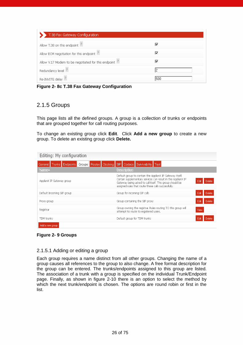
Figure 2- 8b Endpoint Registration Options The T.38 Fax Gateway Configuration options have been provided to aid interoperability with endpoints boasting support for T.38 Fax Gateway functionality. Allow T.38 on this endpoint will enable T.38 on this endpoint. So, upon fax tone detection a T.38 re-INVITE will be sent to this endpoint. Disabling Allow ECM negotiation for this endpoint will prevent ECM (error correction mode) from being negotiated with this endpoint. The Redundancy Level specifies the number of T.38 fax redundancy packets that are sent. Re-INVITE delay is the length of time in milliseconds that the Gateway will wait before sending a re-INVITE to a T.38 endpoint when a CNG tone is detected.
26 of 75
Figure 2- 8c T.38 Fax Gateway Configuration
2.1.5 Groups
This page lists all the defined groups. A group is a collection of trunks or endpoints that are grouped together for call routing purposes. To change an existing group click Edit. Click Add a new group to create a new group. To delete an existing group click Delete.
Figure 2- 9 Groups
2.1.5.1 Adding or editing a group
Each group requires a name distinct from all other groups. Changing the name of a group causes all references to the group to also change. A free format description for the group can be entered. The trunks/endpoints assigned to this group are listed. The association of a trunk with a group is specified on the individual Trunk/Endpoint page. Finally, as shown in figure 2-10 there is an option to select the method by which the next trunk/endpoint is chosen. The options are round robin or first in the list.

27 of 75
Figure 2-10 Edit Group
2.1.6 Routes
This page allows modification of the routes assigned to a group. The drop down box at the top allows you to select the group that you wish to route from, see figure 2 – 11 Editing Routes.
Figure 2-11 Editing Routes

28 of 75
By default the Use the same rules for all groups option is enabled and the Allow calls from unknown endpoints option is disabled. When Use the same rules for all groups is enabled, routing rules that route based on the destination and/or originating address are required. These rules are applied to all routing groups. This is the easiest method to use when configuring the Gateway as it automatically deals with cases where the Gateway is diverted or transferred to itself by a SIP endpoint. When Use the same rules for all groups is disabled, each routing group has its own list of routing rules that are applied to incoming calls. When SIP supplementary features are in use (e.g. diversion or transfer) this can sometimes result in the Gateway being asked to call itself. In a configuration where this is likely to happen you will need to set up routing rules for the ApplianX IP Gateway group that allow these calls to be routed to the correct destination. The Allow calls from unknown endpoints option controls the ability of the Gateway to route calls from endpoints that it doesn’t know about. When this option is enabled, calls from unknown endpoints match the Default SIP Endpoint endpoint and are routed according to the rules assigned to the Default incoming SIP group. The default SIP endpoint can be moved to another group of your choice. Routes can be added using the Add button. The DDI Criteria and CLI Criteria fields define the pattern used to match the dialled destination address and originating address. The following characters are used to define the pattern:
% matches any sequence of digits
? matches any single digit
individual digits match themselves For example, 81% will match any number beginning with 81, whereas 8??2 will match any 4 digit number beginning with an 8 and ending with a 2. The DDI and CLI Manipulation fields define how the destination and originating addresses will be changed. The following characters are used to define the translation:
? uses the next character from the incoming string
! deletes the next character from the incoming string
% uses the remainder of the incoming string (any further characters in the translation string will be ignored)
$ deletes the remainder of the incoming string
Any other digit is copied to the outgoing string. For example, if the incoming destination number is 8120 and the destination address manipulation field is set to 123!% then the destination address used for the outgoing call will be 123120. When local survivability is in active mode, the destination address is manipulated before a contact address is searched for. Additionally, if the call is from a local alias, the originating address will not be manipulated. By selecting the edit icon on the right of any routes, advanced options are available for that route. Figure 2-12 shows this.
29 of 75
2.1.6.1 Routes and Local Survivability
Routes to the Registrar group are a special case and are only valid in configurations which have the local survivability function enabled (ie. they have a designated central PBX endpoint). They are consulted when local survivability is active and are not required for any other purpose. When local survivability is passive, SIP calls arriving from offsite are expected to arrive via the central PBX, SIP calls from other sources are not supported. SIP calls from local users are routed to the central PBX. When local survivability is active, SIP calls from offsite are neither expected nor supported. If you are using local survivability you should have routes from your TDM groups to the Registrar group and also routes from your local SIP users (ie. from the ApplianX IP Gateway registered users endpoint) to the Registrar group. These will enable calls to be routed from TDM trunks to local SIP users and from local SIP users to each other. Additionally, routes should be configured to direct local SIP users to TDM trunks. These will be consulted only when local survivability is active.

30 of 75
Figure 2-12 Advanced Route Options The Codecs option allows different codecs to be selected for a particular route. The transport option allows UDP or TCP to be the default for outgoing calls. The fax option controls the behaviour for incoming fax calls. By default these options will defer to the global settings that can be set in the General, SIP and Codecs sections of the Gateway configuration pages. Following these are a number of options to force the Gateway to use particular values for screening, presentation, originating address plan and type and destination address plan and type.

31 of 75
For voice calls, the echo cancellation set of options govern whether echo cancellation is enabled or not, as well as various other customisable aspects, as described here. The Apply echo cancellation check box will enable or disable echo cancellation on input signals. The Apply automatic gain control check box will enable or disable automatic gain control (AGC) on the input signal. Simply put, this feature ensures a call maintains more or less the same volume, throughout the call. The Echo cancellation span field for the majority of deployments this value can be left at 0, which would trigger the use of a predetermined default value. The most advanced form of echo cancellation on the Gateway is activated by enabling the Use non-linear processing check box. By default this is enabled. The non-linear processing technology can be further customised by changing the value in Non-linear processing limit field. Residual echo on a signal is replaced with “comfort noise”, when Generate background noise is enabled. When this is disabled then complete silence is heard when neither party in the call are speaking. By default this is enabled, which is the best solution, as comfort noise is usually a good indicator that a call is still active when no speech is present.
Figure 2-13 Advanced tone detection/elimination options The Tone Elimination section presents some options to allow a user to customise the elimination of DTMF tones from calls. The Minimum duration of tone specifies the amount of DTMF tone to be present before it is considered to be DTMF tone and hence eliminated. The Tone detection minimum duration is by default set to No minimum. This will cause the Gateway to eliminate tones as soon as a sample of audio can be identified

32 of 75
as containing tone. Other valid values are 40mS and 64mS. These values will require at least 40 milliseconds or 64 milliseconds of tone before elimination from the outgoing audio begins. The Call leg option should be set according to which leg tones are expected to arrive on. If an incoming call is expected to carry DTMF then Incoming call should be selected as the Call leg to eliminate tone on. If an outgoing call is expected to carry DTMF then Outgoing call should be selected as the Call leg to eliminate tone on. The Tone detection section will check which SIP DTMF transmission method is currently selected and will present the appropriate Tone detection min duration options in a dropdown box as shown in Figure 2-13. When the SIP DTMF transmission method is RFC 2833 the options available are No minimum and 40 milliseconds. When the method is SIP-INFO or SIP-INFO-RELAY the options available are the same as for RFC 2833 but with an additional 64 milliseconds option. The No minimum option will typically expect an audio signal sample to contain less than 40 milliseconds of tone before accepting the presence of tone. Setting the tone detection minimum duration to 40 milliseconds or 64 milliseconds will mean that for the Gateway to gateway tones, a tone must be present in the audio signal for at least 40 or 64 milliseconds respectively. The Gateway will generate an appropriate SIP message based on which SIP DTMF method was agreed upon during the initial SIP INVITE transaction.
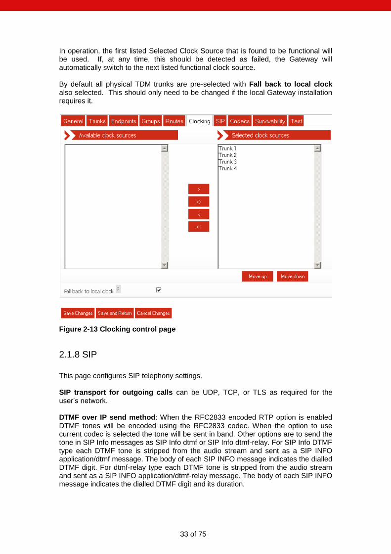
2.1.7 Clocking
This page controls the source of the Gateway’s telephony clock. A correctly configured clock is essential for proper operation of the Gateway. The page displays two columns. The left-hand column shows the Available Clock Sources. These are all the TDM Trunks not currently selected as a possible clock source. The right-hand column shows Selected Clock Sources. These TDM Trunks are currently selected as possible clock sources. To move an “Available” trunk to the “Selected” column, highlight it and then click the “>” button. To move a “Selected” trunk to the “Available” column, highlight it and click the “<” button. To move all “Available” trunks to the “Selected” column, click the “>>” button. To move all “Selected” trunks to the “Available” column, click the “<<” button. The Selected Clock Sources are listed in the order of application. This order can be changed by highlighting individual trunks and then selecting Move Up or Move Down.
There is an additional option to fallback to a locally generated clock source when no other clock source is available.
33 of 75
In operation, the first listed Selected Clock Source that is found to be functional will be used. If, at any time, this should be detected as failed, the Gateway will automatically switch to the next listed functional clock source. By default all physical TDM trunks are pre-selected with Fall back to local clock also selected. This should only need to be changed if the local Gateway installation requires it.
Figure 2-13 Clocking control page
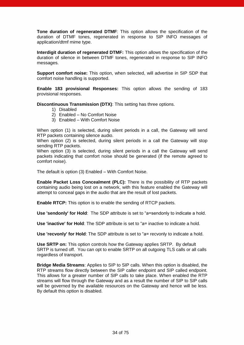
2.1.8 SIP
This page configures SIP telephony settings. SIP transport for outgoing calls can be UDP, TCP, or TLS as required for the user’s network. DTMF over IP send method: When the RFC2833 encoded RTP option is enabled DTMF tones will be encoded using the RFC2833 codec. When the option to use current codec is selected the tone will be sent in band. Other options are to send the tone in SIP Info messages as SIP Info dtmf or SIP Info dtmf-relay. For SIP Info DTMF type each DTMF tone is stripped from the audio stream and sent as a SIP INFO application/dtmf message. The body of each SIP INFO message indicates the dialled DTMF digit. For dtmf-relay type each DTMF tone is stripped from the audio stream and sent as a SIP INFO application/dtmf-relay message. The body of each SIP INFO message indicates the dialled DTMF digit and its duration.
34 of 75
Tone duration of regenerated DTMF: This option allows the specification of the duration of DTMF tones, regenerated in response to SIP INFO messages of application/dtmf mime type. Interdigit duration of regenerated DTMF: This option allows the specification of the duration of silence in between DTMF tones, regenerated in response to SIP INFO messages. Support comfort noise: This option, when selected, will advertise in SIP SDP that comfort noise handling is supported. Enable 183 provisional Responses: This option allows the sending of 183 provisional responses. Discontinuous Transmission (DTX): This setting has three options.
1) Disabled 2) Enabled – No Comfort Noise 3) Enabled – With Comfort Noise
When option (1) is selected, during silent periods in a call, the Gateway will send RTP packets containing silence audio. When option (2) is selected, during silent periods in a call the Gateway will stop sending RTP packets. When option (3) is selected, during silent periods in a call the Gateway will send packets indicating that comfort noise should be generated (if the remote agreed to comfort noise). The default is option (3) Enabled – With Comfort Noise. Enable Packet Loss Concealment (PLC): There is the possibility of RTP packets containing audio being lost on a network, with this feature enabled the Gateway will attempt to conceal gaps in the audio that are the result of lost packets. Enable RTCP: This option is to enable the sending of RTCP packets. Use 'sendonly' for Hold: The SDP attribute is set to “a=sendonly to indicate a hold. Use 'inactive' for Hold: The SDP attribute is set to “a= inactive to indicate a hold. Use 'recvonly' for Hold: The SDP attribute is set to “a= recvonly to indicate a hold. Use SRTP on: This option controls how the Gateway applies SRTP. By default SRTP is turned off. You can opt to enable SRTP on all outgoing TLS calls or all calls regardless of transport. Bridge Media Streams: Applies to SIP to SIP calls. When this option is disabled, the RTP streams flow directly between the SIP caller endpoint and SIP called endpoint. This allows for a greater number of SIP calls to take place. When enabled the RTP streams will flow through the Gateway and as a result the number of SIP to SIP calls will be governed by the available resources on the Gateway and hence will be less. By default this option is disabled.
35 of 75
Figure 2-14a SIP configuration page (part 1)
Require SRTP on incoming calls: When this option is enabled, the Gateway will reject incoming calls that do not specify SRTP in their SDP. For incoming SIP calls, the SIP listening ports can be changed if required from the default of 5060 (for TCP and UDP) and 5061 (for TLS). In addition, by default, the SIP service will listen on both UDP and TCP ports for incoming calls. If either of these is not required, enter 0 (zero) to disable the port. NOTE: If both ports are set to 0 (zero), the Gateway will be unable to make or receive SIP calls. Endpoint Monitoring is enabled on a per-endpoint basis. You can control the interval between polling attempts with the Polling Interval option. Call diversion enabled: When enabled, the Gateway will process diversion information for all SIP calls. History-Info Message Preferred: When enabled, the Gateway will use ‘History-Info’ headers to convey diversion information. When disabled, ‘diversion’ headers will be used.

36 of 75
Divert as proxy: When enabled, the Gateway will make a new ‘diverting’ call if a divert request is received from an outgoing call. When disabled, the Gateway will route divert request information received from an outgoing call to the associated incoming call. Divert unmatched to outgoing group: This option is only applicable when 'Divert as proxy' is enabled. After receiving a divert request, the Gateway will search for a suitable destination group on which to make the diverting call (Its decision is based on the divert-to address received and the routing rule configuration). When this option is enabled, if no suitable group can be found the diverting call will be made on the same group as the residing outgoing call. When disabled, if no suitable group can be found the diversion will be aborted. Send Diverted Address: When enabled, incoming calls will be informed of diversions that have occurred on outgoing call legs. When disabled, incoming calls will not be informed of diversions that have occurred on outgoing call legs. Exchange transfer information: Exchange Route Optimisation/Path Replacement information: Following a call transfer involving a SIP endpoint, it is possible that two TDM endpoints may be connected over a SIP call leg where the Gateway has called itself. To support subsequent transfers or for DPNSS Route Optimisation or QSIG Path Replacement, the Gateway will send itself custom SIP INFO messages. In the unlikely event that this causes problems, either of these features can be disabled here. CBWF/CBWNU Enabled: When enabled, this option allows CallBackWhenFree / CallBackWhenNextUsed supplementary service information to be conveyed over SIP to another Gateway.

37 of 75
Figure 2-14b SIP configuration page (final part)
38 of 75
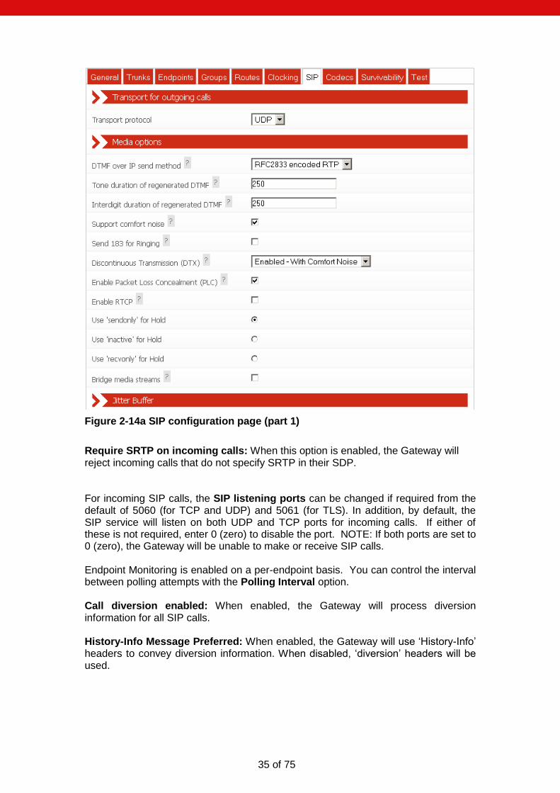
2.1.9 Codecs
The Gateway can negotiate and exchange RTP audio with SIP devices using a range of codecs. This page allows the selection and prioritisation of these codecs. The page displays two columns. The left-hand column shows the Available Codecs. These are all the codecs not currently selected. The right-hand column shows Configured Codecs. These codecs are currently selected. To move an “Available” codec to the “Configured” column, highlight it and then click the “>” button. To move a “Configured” codec to the “Available” column, highlight it and click the “<” button. To move all “Available” codecs to the “Configured” column, click the “>>” button. To move all “Configured” codecs to the “Available” column, click the “<<” button. The Configured Codecs are listed in the order that they will be offered in a SIP INVITE SDP. This is also the order of preference when accepting a SIP INVITE. This order can be changed by highlighting individual codecs and then selecting Move Up or Move Down.
Figure 2-15 Codec configuration page

39 of 75
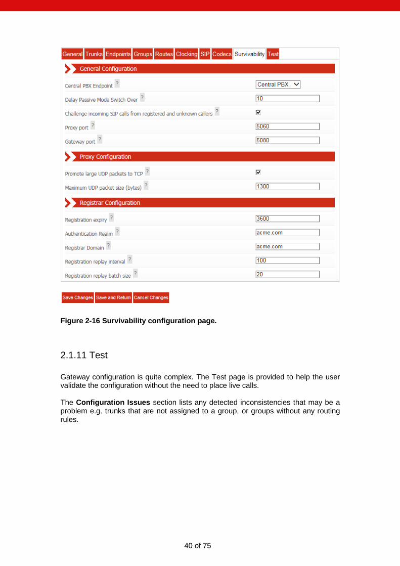
2.1.10 Survivability
To use local branch survivability, select the appropriate SIP endpoint to be the central PBX in the Central PBX Endpoint dropdown box. Otherwise set this to [Disabled]. Delay Passive Mode Switch Over is the time in seconds from when the connection to the central PBX has been restored to when the Gateway local survivability function is switched from active mode to passive mode (see 3.7 Local Survivability for clarification on active versus passive mode) . Ticking the Challenge incoming SIP calls from registered and unknown callers will cause the Gateway to demand incoming SIP endpoints to authenticate themselves, before allowing calls to succeed. The port used by the Gateway proxy process (see 3.7 Local Survivability) is specified by Proxy port. The port the Gateway engine receives SIP calls on is specified by Gateway port. Please do not set Proxy port and Gateway port to the same value. It’s recommended that, Promote large UDP packets to TCP, is enabled. Certain SIP PBX can decorate SIP message headers with long strings of characters which lead to SIP messages that can be very large. The Gateway proxy will promote a large UDP packet to TCP to ensure success. Promotion from UDP to TCP will occur when the value specified in Maximum UDP packet size (bytes) is exceeded. Registration expiry is the maximum number of seconds each new registration is valid for when Gateway local survivability is active. Any local users registering will be limited to this value. It is recommended to keep this value lower than values used by the central PBX – failure to do so may result in loss of registration when connectivity is restored. Authentication Realm must be that of the central PBX. Registrar Domain is typically the same as Authentication Realm and should match that of the central PBX. When local survivability switches from active to passive mode (i.e. connectivity to the central PBX has been restored), local user registrations are replayed to the central PBX. Registration replay batch size controls how many registrations are replayed in a single burst. Between each batch, replay will pause for Registration replay interval seconds. Adjust these parameters to prevent the central PBX from being overloaded with registrations when connectivity is restored.
40 of 75
Figure 2-16 Survivability configuration page.
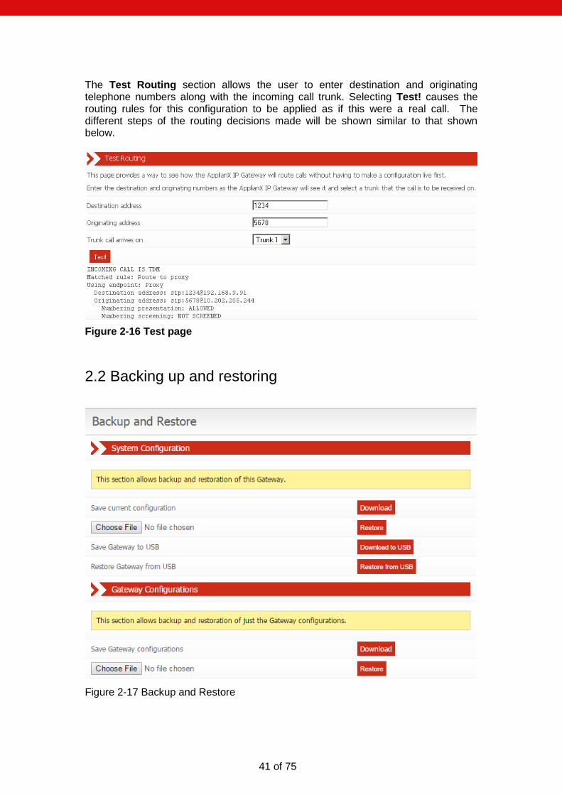
2.1.11 Test
Gateway configuration is quite complex. The Test page is provided to help the user validate the configuration without the need to place live calls. The Configuration Issues section lists any detected inconsistencies that may be a problem e.g. trunks that are not assigned to a group, or groups without any routing rules.
41 of 75
The Test Routing section allows the user to enter destination and originating telephone numbers along with the incoming call trunk. Selecting Test! causes the routing rules for this configuration to be applied as if this were a real call. The different steps of the routing decisions made will be shown similar to that shown below.
Figure 2-16 Test page
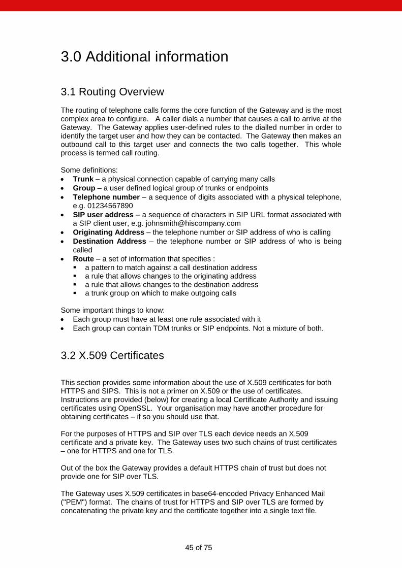
2.2 Backing up and restoring
Figure 2-17 Backup and Restore

42 of 75
To save or restore configuration information select Global Configuration under the System Configuration section in the main menu. This will reveal further options. From here select Backup and Restore. This will bring up the backup and restore page as shown below in Figure 2-17. NOTE: Saved configurations contain potentially sensitive information and should be stored securely.
2.2.1 System configuration
Download and restore all system settings (including Gateway configurations). Select Download to save the current configuration for this Gateway to your local disk. The saved configuration will be named applianx.tgz (or similar). To restore a previously saved configuration select Choose File, find the saved configuration on your local disk and then click Restore. If this is successful then you will see the message as shown in figure 2-18 below.
Figure 2-18 Backup restored
2.2.1.1 Saving and restoring the system configuration via USB port
A USB port is located at the front of the Gateway. By selecting Download to USB, the system configuration can be saved directly to a USB storage device attached to this port. To restore the system configuration from USB, ensure that the backup file (applianx.tgz) is present on your USB storage device, attach the storage device to the USB port and select Restore from USB. The Gateway will apply the saved configuration and restart. The Gateway will come into service with the settings in the saved configuration. The configuration file must be called applianx.tgz. The USB storage device should be non-bootable (ie, the boot sector must be empty) and may contain other arbitrary files. NOTE: When starting up, the Gateway will always attempt to restore the system configuration from USB in preference to the currently installed configuration.

43 of 75
2.2.2 Gateway Configurations
Download and restore Gateway configurations – including local registrar aliases and some elements of the Global configuration. Other system settings are not saved. This feature is useful when multiple Gateway devices are to be deployed with the same or a similar set of Gateway configurations, yet possessing their own unique system settings such as network addresses. Typically a source Gateway device will be configured and tested. Once the operator is satisfied with the Gateway configuration(s), they can be downloaded (see figure 2-17). The downloaded configurations can then be restored to other Gateway devices.
2.3 Factory Reset
Note: Factory reset will erase any configuration changes you have made and restore the Gateway to the state it was when it left the factory. Of particular interest will be that the Gateway Admin IP address will be reset to the static address, 192.168.1.100. Gateway variants differ with respect to factory reset as detailed in the following sections.
2.3.1 Gateway
To perform a factory reset:
Reboot the Gateway. This can be accomplished in one of three ways 1) Via the Restart page on the web interface 2) By inserting an appropriately sized tool into the Reset button hole on the front
panel of your Gateway. The Reset button has to be held in for about a second until all the LEDs extinguish.
3) Or turn off the power and turn it back on again.
Watch the LEDs on the front panel when the Gateway is rebooting. You need to briefly press the reset button (don’t hold it in too long), when the “Warning” LED is lit the first time (approximately four seconds into the boot sequence).
The Error light will illuminate and then the LEDs will go out leaving only the power LED and Initialising LED on. There will be a short period where it appears as though nothing happens. Then the Gateway will reboot.
It will take approximately 4 minutes for the factory reset to complete.
2.3.2 Gateway MkII
For this variant of the Gateway, the factory reset procedure is as follows. While in the ready state, press the recessed Reset button. The button can be found next to the Power LED on the front panel. “Please note that this procedure will mean the MKII Gateway will take some additional time to return to the default no configuration state. Once in this state it will cause the “Initialising” and “ Warning” LEDs to be lit notifying the user that the web interface is now accessible”.

44 of 75
2.4 Shutdown
The Gateway MkII features a power on/off button on the front panel. This button offers two different functions, they are as follows.
1 In the ready state, a quick press of the button will instruct the Gateway to cleanly shutdown.
2 A press and hold will instruct the Gateway to cut the power and turn off immediately.
Please note that both the above functions will result in any active calls being disconnected immediately.
45 of 75
3.0 Additional information
3.1 Routing Overview
The routing of telephone calls forms the core function of the Gateway and is the most complex area to configure. A caller dials a number that causes a call to arrive at the Gateway. The Gateway applies user-defined rules to the dialled number in order to identify the target user and how they can be contacted. The Gateway then makes an outbound call to this target user and connects the two calls together. This whole process is termed call routing. Some definitions:
Trunk – a physical connection capable of carrying many calls
Group – a user defined logical group of trunks or endpoints
Telephone number – a sequence of digits associated with a physical telephone, e.g. 01234567890
SIP user address – a sequence of characters in SIP URL format associated with a SIP client user, e.g. [email protected]
Originating Address – the telephone number or SIP address of who is calling
Destination Address – the telephone number or SIP address of who is being called
Route – a set of information that specifies : a pattern to match against a call destination address a rule that allows changes to the originating address a rule that allows changes to the destination address a trunk group on which to make outgoing calls
Some important things to know:
Each group must have at least one rule associated with it
Each group can contain TDM trunks or SIP endpoints. Not a mixture of both.
3.2 X.509 Certificates
This section provides some information about the use of X.509 certificates for both HTTPS and SIPS. This is not a primer on X.509 or the use of certificates. Instructions are provided (below) for creating a local Certificate Authority and issuing certificates using OpenSSL. Your organisation may have another procedure for obtaining certificates – if so you should use that. For the purposes of HTTPS and SIP over TLS each device needs an X.509 certificate and a private key. The Gateway uses two such chains of trust certificates – one for HTTPS and one for TLS. Out of the box the Gateway provides a default HTTPS chain of trust but does not provide one for SIP over TLS. The Gateway uses X.509 certificates in base64-encoded Privacy Enhanced Mail ("PEM") format. The chains of trust for HTTPS and SIP over TLS are formed by concatenating the private key and the certificate together into a single text file.
46 of 75
The Gateway will check the validity of its certificates nightly and will warn of expired or nearly expired certificates via SNMP. The Gateway will warn ten days prior to the expiry of a TLS or HTTPS certificate. Certificate problems are also indicated on the Overview page. The check for validity is also re-run whenever a change is made to the HTTPS or TLS configuration and this will also lead to the generation of SNMP traps.
3.3 Creating X.509 certificates using OpenSSL
These instructions assume you have downloaded OpenSSL and PERL for your platform. Most Unix-like operating systems (including OS X) will include both PERL and OpenSSL or make it available from their software repositories. For Windows you can obtain OpenSSL by visiting the official OpenSSL website. PERL can be obtained from the official Perl website. NOTE: Your organisation may have a set procedure for obtaining certificates. If so, you should follow that procedure rather than these instructions. First, you need a Certificate Authority which will issue certificates for your devices. You only need to create this once and you should keep a backup of it. There are a number of ways of doing this using OpenSSL to issue certificates, but for this we will use the CA.pl PERL script that is provided in the OpenSSL package. On a Unix-like system this could be in /usr/lib/ssl/misc/ or /usr/share/ssl/misc/CA. On
Windows it will be in the bin directory of the OpenSSL distribution.
In the following instruction, replace the path/to/CA.pl with the appropriate path
for your system. Unless otherwise noted, all commands will work on Windows and Unix-like operating systems. Here the “>” represents a command line prompt for an operating system shell, your prompt maybe different. Commands for you to type are in italics. Make sure that both the perl and openssl executables are in your path. CA.pl will create a certificate database in your current directory so first you need to create a directory to work in.
Create a new Certificate Authority:
> mkdir certificates
> cd certificates

47 of 75
Here you need to enter a secure pass phrase for your Certificate Authority. This is intended to keep your CA secure and make it harder for somebody to issue certificates. You need to remember this phrase as you will need it to issue certificates.
You will be prompted for further information about your CA. You can optionally enter a number of things to provide information about your certificate.
That's all of the information you need to give. The tool will now prompt you for the Certificate Authority pass phrase so it can print out information about the certificate:
> perl /path/to/CA.pl –newca
CA certificate filename (or enter to create) [ENTER]
Making CA certificate ...
Loading 'screen' into random state - done
Generating a 1024 bit RSA private key
....................................................................+++++
+
.++++++
writing new private key to './demoCA/private/cakey.pem'
Enter PEM pass phrase:
Verifying - Enter PEM pass phrase:
Enter the same phrase again.
-----
You are about to be asked to enter information that will be incorporated
into your certificate request.
What you are about to enter is what is called a Distinguished Name or a
DN.
There are quite a few fields but you can leave some blank
For some fields there will be a default value,
If you enter '.', the field will be left blank.
-----
Country Name (2 letter code) [AU]:UK
State or Province Name (full name) [Some-State]:Bucks
Locality Name (eg, city) []:Milton Keynes
Organization Name (eg, company) [Internet Widgits Pty Ltd]:Wainwright's
Fruit Emporium
Organizational Unit Name (eg, section) []:Kiwi Division
Common Name (eg, YOUR name) []:Wayne Wainwright
Email Address []:[email protected]
Please enter the following 'extra' attributes
to be sent with your certificate request
A challenge password []:
An optional company name []:
Using configuration from C:\OpenSSL\bin\openssl.cnf
Loading 'screen' into random state – done

48 of 75
Now you have a Certificate Authority, you can use it to create certificates for devices on your network. Creating a certificate is a two step process. Firstly you need to create a certificate request. As part of this process a private key is created for the device. Once the request has been generated you need to sign the certificate with the Certificate Authority's key.
You will be prompted for a pass phrase for the private key. You can remove the pass phrase later.
Next you will be prompted for information about the device that the certificate is for.
Enter pass phrase for ./demoCA/private/cakey.pem:
Check that the request matches the signature
Signature ok
Certificate Details:
Serial Number:
82:ac:ff:1e:be:8c:16:32
Validity
Not Before: Nov 13 12:46:21 2009 GMT
Not After : Nov 12 12:46:21 2012 GMT
Subject:
countryName = UK
stateOrProvinceName = Bucks
organizationName = Wainwright's Fruit Emporium
organizationalUnitName = Kiwi Division
commonName = Wayne Wainwright
emailAddress = [email protected]
X509v3 extensions:
X509v3 Subject Key Identifier:
6D:8D:85:42:CA:91:B6:FB:F9:CB:53:CE:10:62:15:B5:45:D3:B7:7B
X509v3 Authority Key Identifier:
keyid:6D:8D:85:42:CA:91:B6:FB:F9:CB:53:CE:10:62:15:B5:45:D3:B7:7
B
DirName:/C=UK/ST=Bucks/O=Wainwright's Fruit
Emporium/OU=Kiwi Div
ision/CN=Wayne Wainwright/[email protected]
serial:82:AC:FF:1E:BE:8C:16:32
X509v3 Basic Constraints:
CA:TRUE
Certificate is to be certified until Nov 12 12:46:21 2012 GMT (1095 days)
Write out database with 1 new entries
Data Base Updated
> perl /path/to/CA.pl -newreq
Loading 'screen' into random state - done
Generating a 1024 bit RSA private key
..............................++++++
...................++++++
writing new private key to 'newkey.pem'
Enter PEM pass phrase:
Verifying - Enter PEM pass phrase:

49 of 75
The important field is the Common Name field which you should set to the DNS name or IP address of the device in question.
Now you need to sign the request to create the certificate:
Now the tool will prompt you for the pass phrase for the Certificate Authority. It will then print the information about the certificate and prompt you to check that you want to sign the certificate.
-----
You are about to be asked to enter information that will be incorporated
into your certificate request.
What you are about to enter is what is called a Distinguished Name or a
DN.
There are quite a few fields but you can leave some blank
For some fields there will be a default value,
If you enter '.', the field will be left blank.
-----
Country Name (2 letter code) [AU]:UK
State or Province Name (full name) [Some-State]:Bucks
Locality Name (eg, city) []:Milton Keynes
Organization Name (eg, company) [Internet Widgits Pty Ltd]:Wainright's
Fruit Emporium
Organizational Unit Name (eg, section) []:Kiwi Division
Common Name (eg, YOUR name) []:192.168.1.1
Email Address []:
Please enter the following 'extra' attributes
to be sent with your certificate request
A challenge password []:
An optional company name []:
Request is in newreq.pem, private key is in newkey.pem
> perl /path/to/CA.pl -sign
Using configuration from C:\OpenSSL\bin\openssl.cnf
Loading 'screen' into random state – done

50 of 75
You now have a key in the current directory called newkey.pem and matching certificate in newcert.pem. Rename these to something more appropriate. You can remove the pass phrase from the key using the following command:
Finally, you will need to concatenate the device private key and certificate together. On Unix-like operating systems:
On Windows:
Enter pass phrase for ./demoCA/private/cakey.pem:
Check that the request matches the signature
Signature ok
Certificate Details:
Serial Number:
82:ac:ff:1e:be:8c:16:33
Validity
Not Before: Nov 13 12:51:22 2009 GMT
Not After : Nov 13 12:51:22 2010 GMT
Subject:
countryName = UK
stateOrProvinceName = Bucks
localityName = Milton Keynes
organizationName = Wainright's Fruit Emporium
organizationalUnitName = Kiwi Division
commonName = 192.168.1.1
X509v3 extensions:
X509v3 Basic Constraints:
CA:FALSE
Netscape Comment:
OpenSSL Generated Certificate
X509v3 Subject Key Identifier:
39:9E:FC:6B:E2:17:B0:D7:8A:7D:B0:21:F0:9A:E8:A9:C7:D9:10:DA
X509v3 Authority Key Identifier:
keyid:6D:8D:85:42:CA:91:B6:FB:F9:CB:53:CE:10:62:15:B5:45:D3:B7:7
B
Certificate is to be certified until Nov 13 12:51:22 2010 GMT (365 days)
Sign the certificate? [y/n]:y
1 out of 1 certificate requests certified, commit? [y/n]y
Write out database with 1 new entries
Data Base Updated
Signed certificate is in newcert.pem
> openssl rsa -in newkey.pem -out newkey2.pem
Enter pass phrase for newkey.pem:
writing RSA key
> cat newkey.pem newcert.pem > newchain.pem
> copy newkey.pem+newcert.pem newchain.pem
51 of 75
You can install the new chain of trust onto your Gateway. For other devices to trust your Gateway you will need to install the Certificate Authority's certificate as a trusted certificate.
3.4 HTTPS
Applies to the RA version of the Gateway only
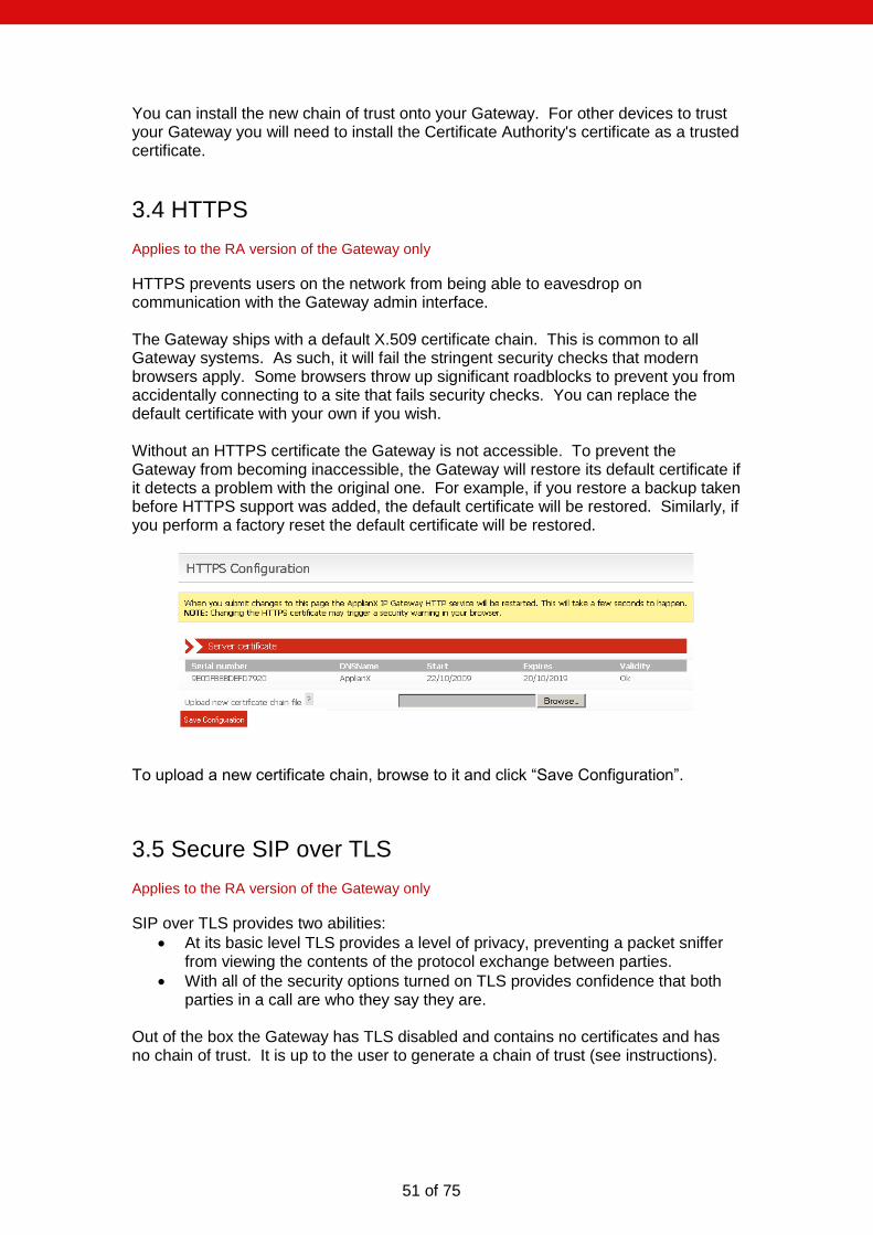
HTTPS prevents users on the network from being able to eavesdrop on communication with the Gateway admin interface. The Gateway ships with a default X.509 certificate chain. This is common to all Gateway systems. As such, it will fail the stringent security checks that modern browsers apply. Some browsers throw up significant roadblocks to prevent you from accidentally connecting to a site that fails security checks. You can replace the default certificate with your own if you wish. Without an HTTPS certificate the Gateway is not accessible. To prevent the Gateway from becoming inaccessible, the Gateway will restore its default certificate if it detects a problem with the original one. For example, if you restore a backup taken before HTTPS support was added, the default certificate will be restored. Similarly, if you perform a factory reset the default certificate will be restored.
To upload a new certificate chain, browse to it and click “Save Configuration”.
3.5 Secure SIP over TLS
Applies to the RA version of the Gateway only
SIP over TLS provides two abilities:
At its basic level TLS provides a level of privacy, preventing a packet sniffer from viewing the contents of the protocol exchange between parties.
With all of the security options turned on TLS provides confidence that both parties in a call are who they say they are.
Out of the box the Gateway has TLS disabled and contains no certificates and has no chain of trust. It is up to the user to generate a chain of trust (see instructions).

52 of 75
NOTE: X.509 certificates contain timestamps that are used to determine their validity. It is important that the clock on the Gateway is accurate – NTP is the recommended method to achieve this. NOTE: TLS protects the SIP session only, to prevent eavesdropping of conversation both TLS and SRTP are required. NOTE: TLS does not prevent a packet sniffer such as Wireshark from determining the parties involved in a conversation. Sometimes this information alone is useful to an interloper. NOTE: TLS is no substitute for paying attention to network security. In particular the peer validation checks can be subverted if an attacker can interfere with the normal operation of DNS on your network (see for example the tools "Cain and Abel" which are just an Internet search away). NOTE: You shouldn't try to make a separate connection for each call - this will put unnecessary load on both endpoints as establishing a TLS connection is very CPU intensive. The Gateway will always attempt to re-use existing TLS connections. NOTE: In the current IP Gateway release it can be difficult to determine the cause for TLS call failure. In particular it is impossible to distinguish between attempting to connect to a non-existent host, a host that doesn't support TLS, or a host that presents an invalid certificate. Packet sniffing using a tool such as Wireshark can shed some light on this.
Changing the following settings will require a reboot of the Gateway:

53 of 75
Use TLS is the system setting that enables or disables TLS. When this option is disabled, the Gateway will not listen for incoming TLS calls and will not be able to make outgoing TLS calls. Require Peer Certificate causes the Gateway to request the remote party's certificate during session negotiation. If the remote party doesn't have a certificate, the negotiation will fail. Maximum chain length controls the number of certificates in the remote party's certificate chain that the Gateway will examine when looking for the signature of a trusted party. This is in addition to the host's own certificate (i.e. if you set the chain length to 1 then a maximum of TWO certificates will be examined). Setting this to 0 will allow the Gateway to examine all certificates in the chain. This setting has a number of implications. Firstly, examining more certificates simply takes longer. A malicious party could present a very long certificate chain, tying up the Gateway for a long period of time. Secondly, each additional certificate in a chain of trust increases the opportunities for an attacker to get hold of a legitimate certificate (e.g. through compromising a host holding a CA and generating a new certificate, through social engineering, etc.). Typically you should set this to the smallest number you can. The Verify remote host address option adds an additional check to the TLS handshake. This check will compare the host name in the certificate against the address of the remote host. If the two do not match then the handshake will fail. For maximum security, all options should be turned on, with the Maximum chain length set to the smallest value that will work for your organisation. The Gateway should be given its own certificate tied to its IP address/DNS name. You should add the certificates for the Certificate Authorities that you have used to issue certificates to other devices on your network. Additionally you can provide Diffie-Hellman parameters to increase the security of the TLS handshake process. The following configuration options do not require a reboot: Sever certificate: This is the certificate chain that the Gateway should present to other devices on the network. You can upload a single chain of trust which should be in base64-encoded Privacy Enhanced Mail (PEM) format and should consist of the private key for the Gateway plus the certificate of the Gateway plus any additional certificates in the chain. For example: -----BEGIN RSA PRIVATE KEY-----
MIICXgIBAAKBgQC7a0ZYUQX0RYI9UZatoZsmpmkBopi7n2s5cDRcxgzlTm7voUC4
eVkEGyyEZ3FfUhdjRZXazhkR1qrjh7PHBbEnz8uAEI8bEiZIRipB+1y/r8Sn75XE
20Z3gO82zergfWnwQ2oRM77fUKJE3jAfth/7x9vKK1A0FDdhZCxfceVfQQIDAQAB
AoGBAJL+YzDXc20Pq0N+n0hVTMO2lvsiVNorAcUN/POanfinWJj3hzRocGmpCnRa
UXAqiY9hv1Pae40jKerEvzrkevldKbOoBr75xYKNf3HXppcSC2z4qkzCu6dY4G3U
TbdbdvBduoeqqERuNZZFT4uV+zpJW7UAQ5ZhT3vL1H9c0XPlAkEA+TaP0+cB/WMJ
+EsORI5SYVNs/QKB/D0Y7z+OmfrjDxUluK+LEkPMDdd7LX4/uDtRAFwhSq2lCNnj
vx+g/oCvdwJBAMCF50IwGqHmspPjFIBLDyDCWMPaMM1QaP2S4GI30dYSjVQxdwyO
6C17ED0f29SZ7JfOUa9XL7ql04fuwC/2xQcCQHwTezZgPDBgv9T74WWmikNkms25
Euh3rtNnDGODcsrOl5JE6/OzB4QYtX4n7ieWeLS6KeUZYSJwASDl6Wzsuu8CQQCA
DRAiH+i24sDISHNsWYA4Y8uyiL+I8ADFGBoSedohrrk91KDAQ5T+GypT3YrTv4Vz
+xCttSnT1VP6x7wgqtulAkEA5sfdjuII4ZyjgNUER82bvtreCuNzj1qw7Q7+sBl8
9FlALfRXTIgJjUVgDBaVEuhQfIFHspOtYmP1TQAoMq49Vw==
-----END RSA PRIVATE KEY-----
-----BEGIN CERTIFICATE-----
MIICYTCCAcoCCQCeBfuL3v15ITANBgkqhkiG9w0BAQUFADB6MRMwEQYDVQQKEwpB

54 of 75
Y3VsYWIgUGxjMREwDwYDVQQLEwhBcHBsaWFuWDETMBEGA1UEBxMKTW91bnQgRmFy
bTEWMBQGA1UECBMNTWlsdG9uIEtleW5lczELMAkGA1UEBhMCVUsxFjAUBgNVBAMT
DUFwcGxpYW5YIFRlYW0wHhcNMDkxMDIzMTAyMTIwWhcNMDkxMDI0MTAyMTIwWjBw
MRMwEQYDVQQKEwpBY3VsYWIgUGxjMREwDwYDVQQLEwhBcHBsaWFuWDETMBEGA1UE
BxMKTW91bnQgRmFybTEWMBQGA1UECBMNTWlsdG9uIEtleW5lczELMAkGA1UEBhMC
VUsxDDAKBgNVBAMTA3JvYjCBnzANBgkqhkiG9w0BAQEFAAOBjQAwgYkCgYEAu2tG
WFEF9EWCPVGWraGbJqZpAaKYu59rOXA0XMYM5U5u76FAuHlZBBsshGdxX1IXY0WV
2s4ZEdaq44ezxwWxJ8/LgBCPGxImSEYqQftcv6/Ep++VxNtGd4DvNs3q4H1p8ENq
ETO+31CiRN4wH7Yf+8fbyitQNBQ3YWQsX3HlX0ECAwEAATANBgkqhkiG9w0BAQUF
AAOBgQCQo+DvcTkMucmPx7CWo/R3KiBEsSbArRKPG2OYqH5E4t4tsqMExOaqg/ts
CwtGlnWLrt/NJidBceG43d/tukLNbNF4hDLFSb01C0CgJoLRZT2bFmtn3C7T6MCg
4J0ujOIhKcdixuDxrQcdVmxzQE+8IPOsawx0pijEL4c8z2i4Iw==
-----END CERTIFICATE-----
If the key has a pass phrase then enter it into the Private key password field. Trusted certificates: These are the certificates that the Gateway will use to validate the chain of trust presented by each remote host. If multiple Certificate Authorities are in use on your network you can upload multiple certificates. You must click on the “Submit changes” button to upload each certificate individually. Diffie-Hellman parameters: These are used during the TLS handshake process to improve security. You can upload 512-bit and 1024-bit parameters. These need to be Base64-encoded.
3.6 Software Updates
From the 2.1.0 release onwards, the Gateway uses a whole-image upgrade method. This overwrites the Gateway software with a different version, allowing upgrade or downgrade to a known version. The user configuration is unaffected by the version change. Update images can be applied either from a USB disk or over a network by an HTTP server. A simple HTTP server is provided by the ax-img-tool utility. A number of caveats apply:
You must not interrupt the upgrade process.
Downgrade to older versions than the 2.1.0 release is not supported.
An older version of the Gateway will not necessarily be able to fully use a configuration generated by a newer version. It is recommended that you take a configuration backup prior to upgrade and use this backup if you should need to downgrade for any reason.
3.6.1 Getting update images
Update images are available from our website.

55 of 75
3.6.2 Getting ax-img-tool
You can download the latest version of this tool from our website.
3.6.3 Validating update images
The Gateway will validate images prior to applying them. This validation helps to ensure that the upgrade is going to succeed. Additionally, you can manually validate an image using the ax-img-tool utility. You can do this for extra confidence when you have downloaded the image over an unreliable connection. Validation can be performed from the command line using the ax-img-tool utility:
Will display:
If the tool reports that the image checksum is bad, don’t attempt to use that image to upgrade your Gateway.
3.6.4 To apply an update image using HTTP
To do this you need to configure an HTTP server to serve the image. Doing this is beyond the scope of this document, however the ax-img-tool can be used as a simple HTTP server and this is described below. NOTE: It is not recommended to install updates directly from the web as Internet connections can be unreliable. NOTE: It doesn't matter what the image is called when this method is used. To use the ax-img-tool as a simple HTTP server run it with the –s option.
ax-img-tool version 1.0
Copyright (C) 2010 Aculab
Image is IPGATEWAY version 2.0.5 (build 52) for a Standard ApplianX
Image was generated on: Tue Apr 13 16:52:38 BST 2010
Verifying checksum (CTRL-C to cancel)....OK
Image is good
c:\Program Files\ApplianX\> ax-img-tool -i name-of-image

56 of 75
By default ax-img-tool listens on all interfaces on port 8000. You can specify the interface to use with the –i option and the port using the –p option. Log into the Gateway web interface and navigate to System Configuration -> Software Updates.
Type the URL of the image into the "HTTP address for image" box. Click "Download using HTTP" button and wait. The image will be downloaded and validated. Assuming the image is valid, the "Apply Image" button will be available.
C:\Program Files\ApplianX\> ax-img-tool -s name-of-image-file
ax-img-tool version 1.0
Copyright (C) 2010 Aculab
Image is IPGATEWAY version 2.0.5 (build 52) for a Standard ApplianX
Image was generated on: Tue Apr 13 16:52:38 BST 2010
Verifying checksum (CTRL-C to cancel)....OK
Image is good
INSTRUCTIONS
============
On your ApplianX go to the Global Configuration -> Software Updates page
Paste the most appropriate of the following addresses into the "Image
Address" field:
http://192.168.1.1:8000/image
http://192.168.9.19:8000/image
http://10.202.205.84:8000/image
Then click on "Download image" to begin the image download.
Use CTRL-C to stop serving the image file

57 of 75
Click “Apply Image” to apply the image. The time required to download the image depends heavily on the speed of your network (on a good network it should take less than 5 minutes). The update will take approximately 10-20 minutes to apply. During this time the Gateway must remain powered on.
Once the update is complete the Gateway must be rebooted. Click on “Reboot Now” to do this:
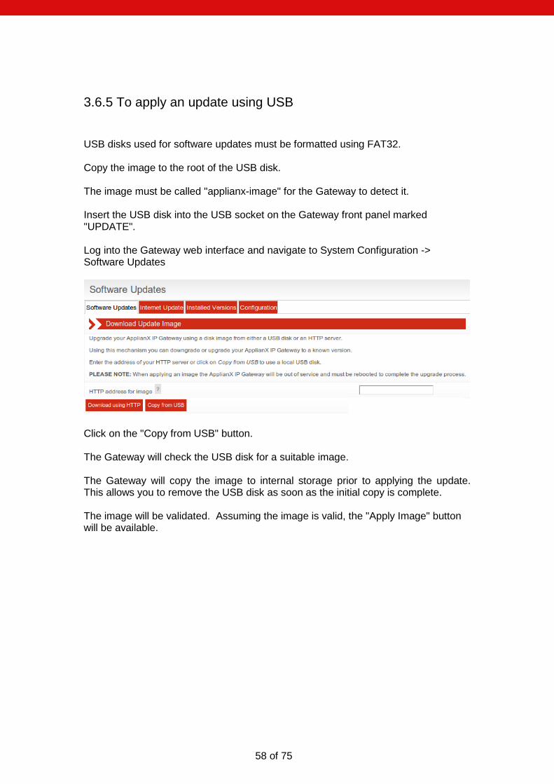
58 of 75
3.6.5 To apply an update using USB
USB disks used for software updates must be formatted using FAT32. Copy the image to the root of the USB disk. The image must be called "applianx-image" for the Gateway to detect it. Insert the USB disk into the USB socket on the Gateway front panel marked "UPDATE". Log into the Gateway web interface and navigate to System Configuration -> Software Updates
Click on the "Copy from USB" button. The Gateway will check the USB disk for a suitable image. The Gateway will copy the image to internal storage prior to applying the update. This allows you to remove the USB disk as soon as the initial copy is complete. The image will be validated. Assuming the image is valid, the "Apply Image" button will be available.

59 of 75
Click “Apply Image” to apply the image. The update will take approximately 10-20 minutes to apply. During this time the Gateway must remain powered on.
Once the update is complete the Gateway must be rebooted. Click on “Reboot Now” to do this:

60 of 75
3.7 Local Survivability
3.7.1 Overview
Local branch survivability is a feature intended to improve the resilience of SIP phones operating in an office that uses a central (SIP) PBX that is located in a different office. The Gateway local survivability function is enabled if an endpoint in the current configuration has been designated as the central PBX. When the central PBX is responding, local survivability is in “passive” mode. If communication with the central PBX is lost, local survivability switches to “active” mode; this allows users in the local office to continue calling each other and out of the office using a back up method (e.g. via the PSTN). The Gateway local survivability function has three components
The Proxy. This is responsible for examining SIP messages as they go past, looking for registration messages.
The Registrar. This is responsible for keeping track of the registration status of local phones in case the central PBX becomes unavailable.
The Gateway engine. This is responsible for routing SIP requests when they are received from the central PBX or the proxy. It takes over central PBX responsibilities if contact is lost.
SIP calls from SIP Phones in the local office are routed to the central PBX by the proxy. If these calls are intended for phones within the office, it is up to the central PBX to route them appropriately. It will do this using the registration information supplied by those phones. Calls destined for the PSTN via the Gateway must be routed back to the Gateway (specifically, the Gateway engine port). In passive mode, the Gateway proxy listens for SIP messages (on port 5060 by default). All requests sent to this port are forwarded to the central PBX. In active mode, requests sent to this port are forwarded to the Gateway engine. The Gateway engine listens for SIP messages on a different port (5080 by default), Calls arriving here can be routed to local SIP users or the PSTN. In passive mode, when making a SIP call, all routing is performed by the central PBX
Central PBX
Proxy
ApplianX
Gateway Engine
SIP SIP
SIP
SIP

61 of 75
If the central PBX becomes unavailable, local survivability will enter active mode. The proxy will then route all requests to the Gateway engine instead of the central PBX. Calls between local users will be possible. Calls to other offices may be possible via the PSTN. Note: After the switch from passive to active mode, SIP calls that were already established may be dropped. This is because the SIP endpoints participating in those calls are likely to have been told by the central PBX to keep it in the signalling path and now that the central PBX is unavailable those messages will not be able to be sent.
3.7.2 Features not supported
Call transfer and divert are not supported when local survivability is in active mode.
3.7.3 Enabling local survivability
To enable the local survivability function the Gateway must be running a configuration that has an endpoint designated to be the central PBX. See section, 2.1.10 Survivability, for more details.
3.7.4 Central PBX responsiveness
Like any SIP endpoint with monitoring enabled, the central PBX is periodically checked for responsiveness. How often it is checked is set by the polling interval option found in 2.1.8 SIP.
3.7.5 Switching to active mode
When the central PBX becomes unresponsive, local survivability will automatically switch to active mode.
Proxy
ApplianX
Gateway Engine
SIP
SIP

62 of 75
3.7.6 Registrar
The Gateway has a simple registrar that can take over local SIP registry responsibilities when the central PBX is down. The registrar requires a list of valid extensions (referred to as user aliases). If SIP devices are using passwords on your network (this is recommended!) then the registrar will need to know these too. For information on how to configure this list, see Uploading a list of users, below. When local survivability is in passive mode (i.e. the central PBX is operating), the registrar will examine registration requests from SIP devices that are using the Gateway as a proxy. The Gateway proxy will not respond to those requests itself but takes note of the response that comes back from the central PBX. When local survivability is in active mode, the Gateway registrar will field registration requests from SIP devices. Any existing registrations will be honoured. In active mode, the Gateway will route calls to the most recently registered address for a given alias. In order for calls to reach registered users there must be at least one routing rule that routes calls to the Registrar group. The Gateway will attempt to route calls that match this rule to an alias known to the registrar. Calls that do not match entries in the registration database will be matched against subsequent routing rules. When the central PBX recovers, local survivability will switch back into passive mode. At this point the Gateway will pass its current registrations on to the central PBX, unregistering phones that are not registered locally, and re-registering phones that are registered locally. Common scenarios It may make sense to create a rule that checks all calls against the Registrar:
If you only want calls with a fixed number of digits to match, add a routing rule like this (each question mark matches one digit):
If calls with a specific prefix should be routed to the registrar, use a rule like this:

63 of 75
More than one rule can be specified:
3.7.7 Configuring SIP devices
All SIP devices are different, but in general:
configure the SIP device to use the Gateway as a proxy.
configure the SIP device to use the central PBX as a registrar (because the Gateway is configured to be the proxy, all registration requests will pass through the Gateway).
for DNS resilience, configure the SIP device to use the Gateway as a DNS server.
On the central PBX, configure the default registration expiry to be relatively short – always shorter than any expiration times used by the central PBX. If the central PBX needs to use the Gateway as a SIP-TDM gateway, configure the central PBX to connect to the “Gateway” port on the Gateway (this is port 5080 by default).
3.7.8 Managing user aliases
A SIP user alias is a user name and corresponding password used by the central PBX to identify a SIP user for registration purposes. A Comma-Separated-Value (CSV) text file containing a list of SIP user aliases maybe uploaded using the ‘Manage Aliases’ web page. In the CSV file, each user is represented by 3 text fields, the format of which is: <USERNAME>,<PASSWORD>,<DESCRIPTION>
For example, the contents of “my_aliases.csv” might read:
joe_bloggs,JoEsPaSsWoRd,Joe is better than Jill
jill_bloggs,JiLlSpAsSwOrD,Jill is better than Joe
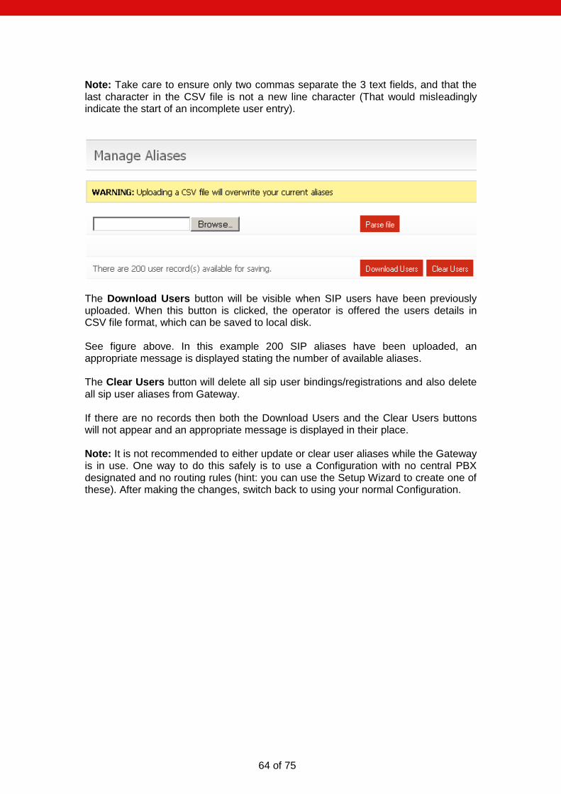
64 of 75
Note: Take care to ensure only two commas separate the 3 text fields, and that the last character in the CSV file is not a new line character (That would misleadingly indicate the start of an incomplete user entry).
The Download Users button will be visible when SIP users have been previously uploaded. When this button is clicked, the operator is offered the users details in CSV file format, which can be saved to local disk. See figure above. In this example 200 SIP aliases have been uploaded, an appropriate message is displayed stating the number of available aliases. The Clear Users button will delete all sip user bindings/registrations and also delete all sip user aliases from Gateway. If there are no records then both the Download Users and the Clear Users buttons will not appear and an appropriate message is displayed in their place. Note: It is not recommended to either update or clear user aliases while the Gateway is in use. One way to do this safely is to use a Configuration with no central PBX designated and no routing rules (hint: you can use the Setup Wizard to create one of these). After making the changes, switch back to using your normal Configuration.
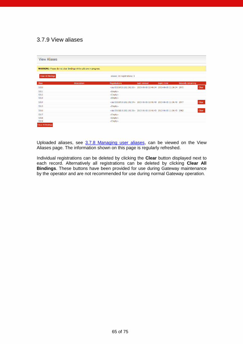
65 of 75
3.7.9 View aliases
Uploaded aliases, see 3.7.8 Managing user aliases, can be viewed on the View Aliases page. The information shown on this page is regularly refreshed. Individual registrations can be deleted by clicking the Clear button displayed next to each record. Alternatively all registrations can be deleted by clicking Clear All Bindings. These buttons have been provided for use during Gateway maintenance by the operator and are not recommended for use during normal Gateway operation.
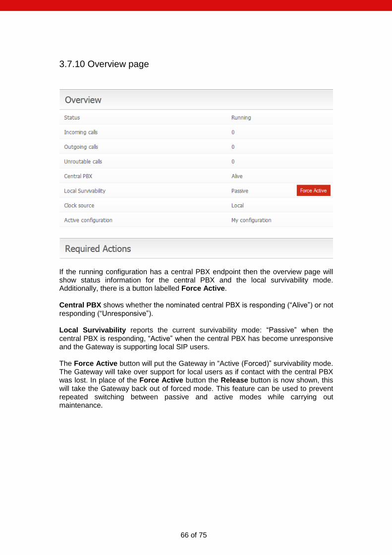
66 of 75
3.7.10 Overview page
If the running configuration has a central PBX endpoint then the overview page will show status information for the central PBX and the local survivability mode. Additionally, there is a button labelled Force Active. Central PBX shows whether the nominated central PBX is responding (“Alive”) or not responding (“Unresponsive”). Local Survivability reports the current survivability mode: “Passive” when the central PBX is responding, “Active” when the central PBX has become unresponsive and the Gateway is supporting local SIP users. The Force Active button will put the Gateway in “Active (Forced)” survivability mode. The Gateway will take over support for local users as if contact with the central PBX was lost. In place of the Force Active button the Release button is now shown, this will take the Gateway back out of forced mode. This feature can be used to prevent repeated switching between passive and active modes while carrying out maintenance.

67 of 75
3.8 DDI barring
This feature allows the administrator to place a restriction on the phone numbers that can be called via the Gateway. The administrator will supply a plain text file containing the list of numbers to be barred. The expected format is
Numeric digits only.
Single entry per line. Whole telephone numbers need not be specified. For example, an entry in the file could be the dialling code for an area or the prefix for a premium rate number. An example of a DDI barring file,
0845
01604
In this example, calls to any premium rate numbers that begin with 0845 will fail, as will calls to Northampton (01604). The administrator is able to clear the barred numbers by clicking the button “Delete Barred numbers file”. The administrator will be given a chance to cancel this action. The administrator is able to download the list of barred numbers by clicking the button “Download Barred DDIs”.
3.9 DNS Caching
The Gateway contains a DNS cache, intended to improve resilience during periods of network instability. The Gateway can be configured with up to two upstream DNS servers on the Network Configuration page. The Gateway will regularly check that these servers are available. If DNS servers become unavailable it will be reported on the Overview page. DNS entries are cached according to the expiry time received from the server and if valid will be used in preference to sending a request to the DNS server. If the DNS server is unavailable, cached entries will be used even if they have expired.

68 of 75
When the local survivability function is enabled, the Gateway proxy will look up hostnames from relevant SIP headers to ensure they are cached locally in case the central PBX fails. Note: The DNS cache will not contain DNS entries for hosts that have not been mentioned in headers seen by the Gateway proxy. To mitigate this, you can enter static DNS entries on the Static DNS page accessed by clicking on the “Networking” menu option.
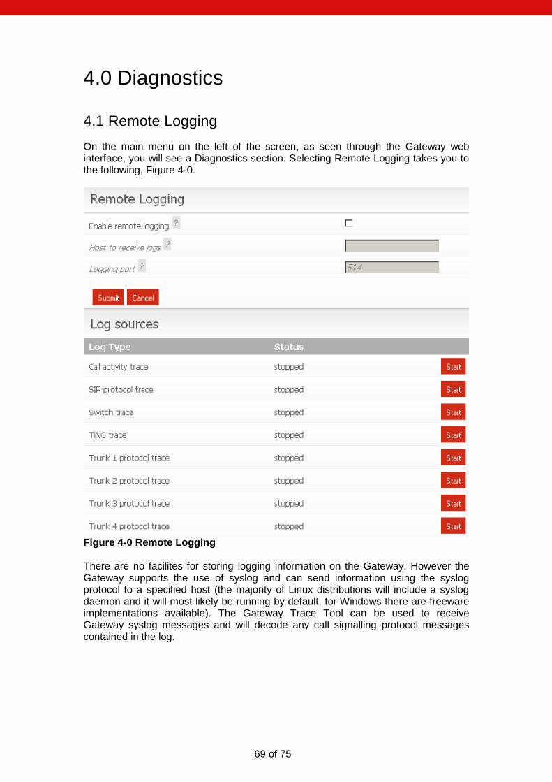
69 of 75
4.0 Diagnostics
4.1 Remote Logging
On the main menu on the left of the screen, as seen through the Gateway web interface, you will see a Diagnostics section. Selecting Remote Logging takes you to the following, Figure 4-0.
Figure 4-0 Remote Logging There are no facilites for storing logging information on the Gateway. However the Gateway supports the use of syslog and can send information using the syslog protocol to a specified host (the majority of Linux distributions will include a syslog daemon and it will most likely be running by default, for Windows there are freeware implementations available). The Gateway Trace Tool can be used to receive Gateway syslog messages and will decode any call signalling protocol messages contained in the log.
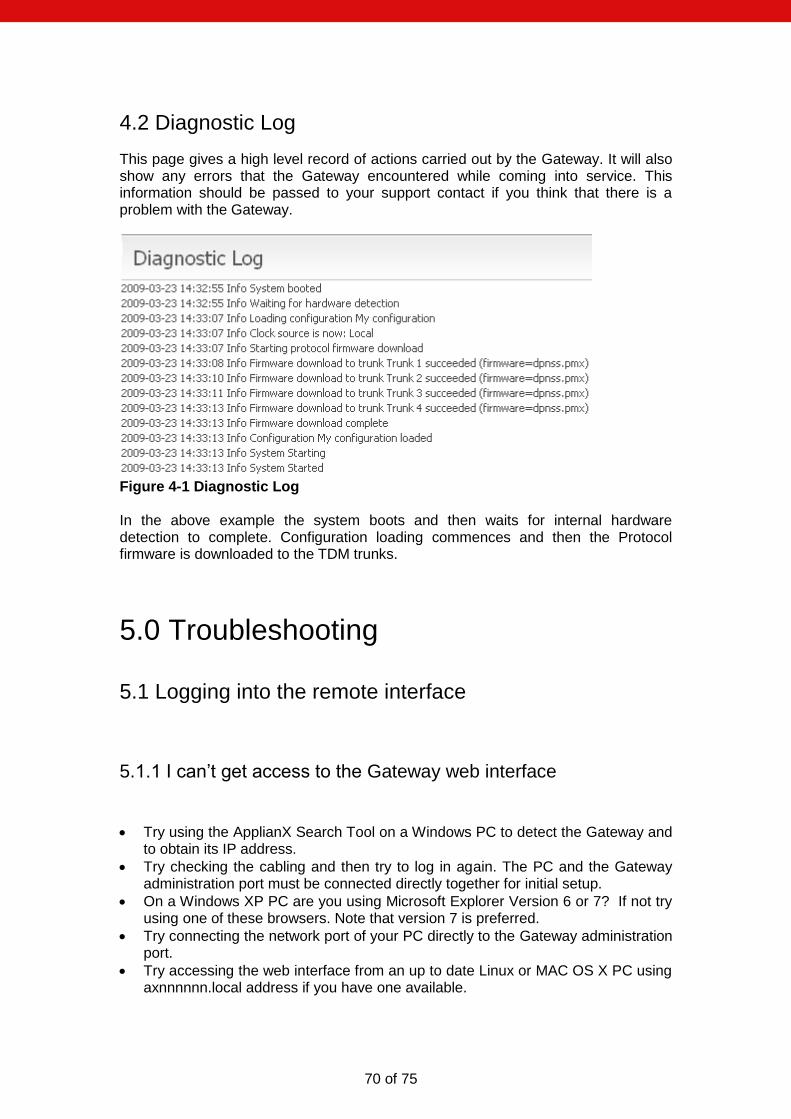
70 of 75
4.2 Diagnostic Log
This page gives a high level record of actions carried out by the Gateway. It will also show any errors that the Gateway encountered while coming into service. This information should be passed to your support contact if you think that there is a problem with the Gateway.
Figure 4-1 Diagnostic Log In the above example the system boots and then waits for internal hardware detection to complete. Configuration loading commences and then the Protocol firmware is downloaded to the TDM trunks.
5.0 Troubleshooting
5.1 Logging into the remote interface
5.1.1 I can’t get access to the Gateway web interface
Try using the ApplianX Search Tool on a Windows PC to detect the Gateway and to obtain its IP address.
Try checking the cabling and then try to log in again. The PC and the Gateway administration port must be connected directly together for initial setup.
On a Windows XP PC are you using Microsoft Explorer Version 6 or 7? If not try using one of these browsers. Note that version 7 is preferred.
Try connecting the network port of your PC directly to the Gateway administration port.
Try accessing the web interface from an up to date Linux or MAC OS X PC using axnnnnnn.local address if you have one available.
71 of 75
Did this work? If so you may have DNS/DHCP network issues. Move to using static IP addresses
Try setting the IP of the admin port to a known static IP address using a USB flash memory stick as described in section 1.9.2.
5.1.2 I log on but the overview screen has warnings at the top
Wait a couple of minutes. The web interface can start before the Gateway, which means that until the Gateway has started, the interface will report that it cannot connect to the Gateway engine.
5.2 Making Calls through the Gateway
5.2.1 I can’t make a call from the TDM side of the Gateway to an IP client.
Check the Call Status Page by selecting “Calls” under the Status section on the menu on the left of the Administration web interface. Now make the call in from the TDM side of the Gateway. Check the Call Activity at the bottom of the screen to see whether the Call was received by the Gateway. In this case you can see that the Gateway did indeed receive the call but could not route it. You will need to check your routing rules so that the Gateway has the information it needs to route the calls. See section 2 of this User Guide.

72 of 75
If there are no calls present then check the Status of the Trunk. This is done by selecting Trunk Status from the Status section of the menu. If the Trunk is good then the Layer 1 should be showing zero for Slips Errors, Bipolar Violations and Frame Alignment Errors. If there are errors on these then please check the cabling. Ensure that you have configured the correct protocol for the TDM trunks. Also check the options that have been chosen for the protocol and ensure that these are in line with the TDM lines that you are connecting to the Gateway.
If there are no Layer 1 Errors then check the Layer 2. If this isn’t showing “green” for the bearer channels on the trunk then there is a layer 2 problem. Check that you have the correct protocol loaded for the TDM trunks that you are connecting to the Gateway. Check with your service provider or PBX maintenance team for set up information for the protocol.

73 of 75
5.3 Configuring the Gateway
5.3.1 I have made changes to the configuration but they don’t seem to have any effect.
The Gateway does not allow you to edit a configuration that is in use. For this reason you can copy a configuration and edit this. Before these changes can take effect you must select that the Gateway use this edited configuration. This is done by selecting the “Use” button by the side of the edited configuration on Edit Configurations page
5.3.2 I used the wizard to create an initial configuration but I have an error saying that there is no active configuration.
On completion of the Wizard a skeleton configuration is created. This configuration though is not automatically activated. On completion of the Wizard you will be directed to the Edit Configurations screen. Here the Skeleton created in the Wizard will be shown under the Available configurations section. Select USE to activate that configuration.
5.4 Local Survivability
5.4.1When the central PBX is back online, phones with the same number but situated at other sites stop working.
A phone located at another site but which is bound to the same number/alias as a local phone may lose contact with the central PBX. For example, if a local phone is bound to an alias of [email protected], then there should be no other phone at a different site which are bound to the same alias.
74 of 75
6.0 Glossary ApplianX – is a product brand of Aculab and has been developed in order to provide robust and reliable systems for the fast execution of Internet-based communication strategies, with rapid deployment and integration into existing infrastructures. CAS – Channel Associated Signalling. This is a type of signalling associated with telephony where some dedicated bits in the transmitted stream are directly used to signal information about a particular voice channel. “T1 Robbed-Bit” is well known example of a CAS protocol used in United States. E1 – 2.048 Mbit full duplex Communication Interface. Used in most countries outside of the United States, Canada and Japan. HTTP - Hypertext Transfer Protocol. Used on the Gateway to send information to and from Web Browsers ISDN – Integrated Services Digital Network. Used within the Gateway and this document to describe the family of protocol that have there origins in the ITU’s Q931 and Q921 specifications. ETS300 102 in Europe and National ISDN 2 (NI2) are typical examples of ISDN protocols. LAYER 1 – Known as the physical layer in the OSI (Open Systems Interconnection) 7 layer model. Responsible only for getting raw bits from one node to another. It has some alarm and error transmitting capabilities. Basically Layer1 accepts requests from Layer 2. LAYER 2 – Known as the data link layer in the OSI (Open Systems Interconnection) 7 layer model. This transfers data between two nodes on the same network. It usually has error detection and possibly correction. Within this document and the Gateway user screens we refer to Layer 2 for TDM protocols. For ISDN protocols this is based upon the ITU (International Telecommunications Union) Q921 standard. LINUX – A Unix like operating system that is supported and distributed by many organisations. Well know distributions include RedHat, Fedora, Suse, Debian and Ubuntu to mention just a few. MAC OS X – The Unix based operating system used on Apple (Apple Incorporated formerly Apple Computers Incorporated) PC’s. PBX – Private Branch eXchange. This is a local switch that traditionally terminates POTS (Plain Old Telephone Service) and routes calls between users and into other switches on TDM networks (and more recently IP networks). SIP – Session Initiation Protocol. A signalling protocol that has been defined by a number of IETF RFCs (Internet Engineering Task Force) that can be used for, among other things, setting up and controlling IP voice communications. The Gateway uses this for the setting up of IP telephony calls. SNMP – Simple Network Management Protocol. This can be set up on the Gateway so that SNMP software ( not supplied ) can be used to monitor elements of the
75 of 75
Gateway status remotely. This requires use of the MIB (Management Information Base) that can be downloaded either from the Gateway itself or from our website. T1 – 1.544 Mbit full duplex Communication Interface. Used mostly in the United States, Canada and Japan. TDM – Time Division Multiplexed. Used in this document to reference the ISDN and CAS Trunks. Also known as the T1 or E1 interfaces on the Gateway Timeslot – A dedicated slot on the TDM interface used for carrying digitised voice and data information. Typically an E1 interface will have 30 of these and T1 will have 23 or 24. TRUNKS – Either an E1 or T1 interface. A wired connection that carries a collection of voice channels and signalling channels. Sometimes the Gateway will refer to “SIP Trunks”. This is a virtual concept that all IP Telephony traffic is a “Trunk”. This is for the benefit of writing routing tables and rules. URI – Uniform Resource Identifier. Within the context of the Gateway this is used for identifying the addresses of SIP User Agents (IP Phones). It is used in the wider networking world and is not SIP specific. USB – Universal Serial Bus. Used with the Gateway for inserting external memory devices for the configuring of IP settings and saving and restoring of configurations. User Agent – Used within this document to indicate a SIP Telephone although it does have meaning in other contexts such as the World Wide Web. Web Interface – This is the User Interface on the Gateway that has been designed to work with a web browser (not supplied) to allow administrators to configure, monitor and maintain the Gateway. Examples of web browsers are Microsoft Internet Explorer (ie6/ie7), Safari, Firefox and Opera to name just a few. ZEROCONF – This is a set of techniques that automatically creates a usable network without DHCP and DNS servers or manual configuration. This is used in the Gateway when the unit is set to DHCP and no DHCP server can be found on the network.