appendix l tcp/ip and osi - webster university
TRANSCRIPT
AA P P E N D I X P P E N D I X LL
T C P / I P a n d O S IT C P / I P a n d O S I
William Stallings
Copyright 2010
L.1 PROTOCOLS AND PROTOCOL ARCHITECTURES ...................................................2!
L.2 THE TCP/IP PROTOCOL ARCHITECTURE..................................................................5!
TCP/IP Layers................................................................................................................5!
TCP and UDP ................................................................................................................7!
Operation of TCP/IP ......................................................................................................7!
TCP/IP Applications ....................................................................................................10!
L.3 THE ROLE OF AN INTERNET PROTOCOL ...............................................................11!
L.4 IPv4...................................................................................................................................13!
L.5 IPv6...................................................................................................................................15!
IPv6 Header .................................................................................................................15!
IPv6 Extension Headers...............................................................................................17!
L.6 THE OSI PROTOCOL ARCHITECTURE .....................................................................20!
Supplement to
Cryptography and Network Security, Fifth Edition
William Stallings
Prentice Hall 2010
ISBN-10: 0136097049
http://williamstallings.com/Crypto/Crypto5e.html
L-2
This appendix provides an overview of the two most widely used protocol architectures.
L.1 PROTOCOLS AND PROTOCOL ARCHITECTURES
When computers, terminals, and/or other data processing devices exchange data, the procedures
involved can be quite complex. Consider, for example, the transfer of a file between two
computers. There must be a data path between the two computers, either directly or via a
communication network. But more is needed. Typical tasks to be performed include the
following:
1. The source system must either activate the direct data communication path or inform the
communication network of the identity of the desired destination system.
2. The source system must ascertain that the destination system is prepared to receive data.
3. The file transfer application on the source system must ascertain that the file management
program on the destination system is prepared to accept and store the file for this
particular user.
4. If the file formats or data representations used on the two systems are incompatible, one
or the other system must perform a format translation function.
The exchange of information between computers for the purpose of cooperative action is
generally referred to as computer communications. Similarly, when two or more computers are
interconnected via a communication network, the set of computer stations is referred to as a
computer network. Because a similar level of cooperation is required between a terminal and a
computer, these terms are often used when some of the communicating entities are terminals.
In discussing computer communications and computer networks, two concepts are
paramount:
• Protocols
• Computer communications architecture, or protocol architecture

L-3
A protocol is used for communication between entities in different systems. The terms
entity and system are used in a very general sense. Examples of entities are user application
programs, file transfer packages, database management systems, electronic mail facilities, and
terminals. Examples of systems are computers, terminals, and remote sensors. Note that in some
cases the entity and the system in which it resides are coextensive (e.g., terminals). In general, an
entity is anything capable of sending or receiving information, and a system is a physically
distinct object that contains one or more entities. For two entities to communicate successfully,
they must "speak the same language." What is communicated, how it is communicated, and
when it is communicated must conform to mutually agreed conventions between the entities
involved. The conventions are referred to as a protocol, which may be defined as a set of rules
governing the exchange of data between two entities. The key elements of a protocol are as
follows:
• Syntax: Includes such things as data format and signal levels
• Semantics: Includes control information for coordination and error handling
• Timing: Includes speed matching and sequencing
Having introduced the concept of a protocol, we can now introduce the concept of a
protocol architecture. It is clear that there must be a high degree of cooperation between the
two computer systems. Instead of implementing the logic for this as a single module, the task is
broken up into subtasks, each of which is implemented separately. As an example, Figure L.1
suggests the way in which a file transfer facility could be implemented. Three modules are used.
Tasks 3 and 4 in the preceding list could be performed by a file transfer module. The two
modules on the two systems exchange files and commands. However, rather than requiring the
file transfer module to deal with the details of actually transferring data and commands, the file
transfer modules each rely on a communications service module. This module is responsible for
making sure that the file transfer commands and data are reliably exchanged between systems.
The manner in which a communications service module functions is explored subsequently.
Among other things, this module would perform task 2. Finally, the nature of the exchange
between the two communications service modules is independent of the nature of the network

L-4
that interconnects them. Therefore, rather than building details of the network interface into the
communications service module, it makes sense to have a third module, a network access
module, that performs task 1 by interacting with the network.
To summarize, the file transfer module contains all the logic that is unique to the file
transfer application, such as transmitting passwords, file commands, and file records. These files
and commands must be transmitted reliably. However, the same sorts of reliability requirements
are relevant to a variety of applications (e.g., electronic mail, document transfer). Therefore,
these requirements are met by a separate communications service module that can be used by a
variety of applications. The communications service module is concerned with assuring that the
two computer systems are active and ready for data transfer and for keeping track of the data that
are being exchanged to assure delivery. However, these tasks are independent of the type of
network that is being used. Therefore, the logic for actually dealing with the network is put into a
separate network access module. If the network to be used is changed, only the network access
module is affected.
Thus, instead of a single module for performing communications, there is a structured set
of modules that implements the communications function. That structure is referred to as a
protocol architecture. An analogy might be useful at this point. Suppose an executive in office X
wishes to send a document to an executive in office Y. The executive in X prepares the
document and perhaps attaches a note. This corresponds to the actions of the file transfer
application in Figure L.1. Then the executive in X hands the document to a secretary or
administrative assistant (AA). The AA in X puts the document in an envelope and puts Y's
address and X's return address on the outside. Perhaps the envelope is also marked
"confidential." The AA's actions correspond to the communications service module in Figure
L.1. The AA in X then gives the package to the shipping department. Someone in the shipping
department decides how to send the package: mail, UPS, or express courier. The shipping
department attaches the appropriate postage or shipping documents to the package and ships it
out. The shipping department corresponds to the network access module of Figure L.1. When the
package arrives at Y, a similar layered set of actions occurs. The shipping department at Y
receives the package and delivers it to the appropriate AA or secretary based on the name on the
package. The AA opens the package and hands the enclosed document to the executive to whom
it is addressed.
L-5
L.2 THE TCP/IP PROTOCOL ARCHITECTURE
TCP/IP is a result of protocol research and development conducted on the experimental packet-
switched network, ARPANET, funded by the Defense Advanced Research Projects Agency
(DARPA), and is generally referred to as the TCP/IP protocol suite. This protocol suite consists
of a large collection of protocols that have been issued as Internet standards by the Internet
Activities Board (IAB). A document at this book's Web site provides a discussion of Internet
standards.
TCP/IP Layers
In general terms, communications can be said to involve three agents: applications, computers,
and networks. Examples of applications include file transfer and electronic mail. The
applications that we are concerned with here are distributed applications that involve the
exchange of data between two computer systems. These applications, and others, execute on
computers that can often support multiple simultaneous applications. Computers are connected to
networks, and the data to be exchanged are transferred by the network from one computer to
another. Thus, the transfer of data from one application to another involves first getting the data
to the computer in which the application resides and then getting the data to the intended
application within the computer.
There is no official TCP/IP protocol model. However, based on the protocol standards that
have been developed, we can organize the communication task for TCP/IP into five relatively
independent layers, from bottom to top:
• Physical layer
• Network access layer
• Internet layer
• Host-to-host, or transport layer
• Application layer

L-6
The physical layer covers the physical interface between a data transmission device (e.g.,
workstation, computer) and a transmission medium or network. This layer is concerned with
specifying the characteristics of the transmission medium, the nature of the signals, the data rate,
and related matters.
The network access layer is concerned with the exchange of data between an end system
(server, workstation, etc.) and the network to which it is attached. The sending computer must
provide the network with the address of the destination computer, so that the network may route
the data to the appropriate destination. The sending computer may wish to invoke certain
services, such as priority, that might be provided by the network. The specific software used at
this layer depends on the type of network to be used; different standards have been developed for
circuit switching, packet switching (e.g., frame relay), LANs (e.g., Ethernet), and others. Thus it
makes sense to separate those functions having to do with network access into a separate layer.
By doing this, the remainder of the communications software, above the network access layer,
need not be concerned about the specifics of the network to be used. The same higher-layer
software should function properly regardless of the particular network to which the computer is
attached.
The network access layer is concerned with access to and routing data across a network for
two end systems attached to the same network. In those cases where two devices are attached to
different networks, procedures are needed to allow data to traverse multiple interconnected
networks. This is the function of the internet layer. The Internet Protocol (IP) is used at this
layer to provide the routing function across multiple networks. This protocol is implemented not
only in the end systems but also in routers. A router is a processor that connects two networks
and whose primary function is to relay data from one network to the other on a route from the
source to the destination end system.
Regardless of the nature of the applications that are exchanging data, there is usually a
requirement that data be exchanged reliably. That is, we would like to be assured that all the data
arrive at the destination application and that the data arrive in the same order in which they were
sent. As we shall see, the mechanisms for providing reliability are essentially independent of the
nature of the applications. Thus, it makes sense to collect those mechanisms in a common layer
shared by all applications; this is referred to as the host-to-host layer, or transport layer. The
L-7
Transmission Control Protocol (TCP) is the most commonly used protocol to provide this
functionality.
Finally, the application layer contains the logic needed to support the various user
applications. For each different type of application, such as file transfer, a separate module is
needed that is peculiar to that application.
TCP and UDP
For most applications running as part of the TCP/IP protocol architecture, the transport layer
protocol is TCP. TCP provides a reliable connection for the transfer of data between
applications. A connection is simply a temporary logical association between two entities in
different systems. For the duration of the connection each entity keeps track of segments coming
and going to the other entity, in order to regulate the flow of segments and to recover from lost or
damaged segments.
Figure L.2a shows the header format for TCP, which is a minimum of 20 octets, or 160
bits. The Source Port and Destination Port fields identify the applications at the source and
destination systems that are using this connection. The Sequence Number, Acknowledgment
Number, and Window fields provide flow control and error control. The checksum is a 16-bit
code based on the contents of the segment used to detect errors in the TCP segment.
In addition to TCP, there is one other transport-level protocol that is in common use as part
of the TCP/IP protocol suite: the User Datagram Protocol (UDP). UDP does not guarantee
delivery, preservation of sequence, or protection against duplication. UDP enables a process to
send messages to other processes with a minimum of protocol mechanism. Some transaction-
oriented applications make use of UDP; one example is SNMP (Simple Network Management
Protocol), the standard network management protocol for TCP/IP networks. Because it is
connectionless, UDP has very little to do. Essentially, it adds a port addressing capability to IP.
This is best seen by examining the UDP header, shown in Figure L.2b.
Operation of TCP/IP
Figure L.3 indicates how these protocols are configured for communications. Some sort of
network access protocol, such as the Ethernet logic, is used to connect a computer to a network.
This protocol enables the host to send data across the network to another host or, in the case of a
L-8
host on another network, to a router. IP is implemented in all end systems and routers. It acts as a
relay to move a block of data from one host, through one or more routers, to another host. TCP is
implemented only in the end systems; it keeps track of the blocks of data being transferred to
assure that all are delivered reliably to the appropriate application.
For successful communication, every entity in the overall system must have a unique
address. In fact, two levels of addressing are needed. Each host on a network must have a unique
global internet address; this allows the data to be delivered to the proper host. This address is
used by IP for routing and delivery. Each application within a host must have an address that is
unique within the host; this allows the host-to-host protocol (TCP) to deliver data to the proper
process. These latter addresses are known as ports.
Let us trace a simple operation. Suppose that a process, associated with port 3 at host A,
wishes to send a message to another process, associated with port 2 at host B. The process at A
hands the message down to TCP with instructions to send it to host B, port 2. TCP hands the
message down to IP with instructions to send it to host B. Note that IP need not be told the
identity of the destination port. All it needs to know is that the data are intended for host B. Next,
IP hands the message down to the network access layer (e.g., Ethernet logic) with instructions to
send it to router J (the first hop on the way to B).
To control this operation, control information as well as user data must be transmitted, as
suggested in Figure L.4. Let us say that the sending process generates a block of data and passes
this to TCP. TCP may break this block into smaller pieces to make it more manageable. To each
of these pieces, TCP appends control information known as the TCP header (Figure L.2a),
forming a TCP segment. The control information is to be used by the peer TCP protocol entity
at host B. Examples of items in this header include
• Destination port: When the TCP entity at B receives the segment, it must know to whom
the data are to be delivered.
• Sequence number: TCP numbers the segments that it sends to a particular destination port
sequentially, so that if they arrive out of order, the TCP entity at B can reorder them.
L-9
• Checksum: The sending TCP includes a code that is a function of the contents of the
remainder of the segment. The receiving TCP performs the same calculation and compares
the result with the incoming code. A discrepancy results if there has been some error in
transmission.
Next, TCP hands each segment over to IP, with instructions to transmit it to B. These
segments must be transmitted across one or more networks and relayed through one or more
intermediate routers. This operation, too, requires the use of control information. Thus IP
appends a header of control information (Figure L.5) to each segment to form an IP datagram.
An example of an item stored in the IP header is the destination host address (in this example,
B).
Finally, each IP datagram is presented to the network access layer for transmission across
the first network in its journey to the destination. The network access layer appends its own
header, creating a packet, or frame. The packet is transmitted across the network to router J. The
packet header contains the information that the network needs in order to transfer the data across
the network. Examples of items that may be contained in this header include:
• Destination network address: The network must know to which attached device the
packet is to be delivered, in this case router J.
• Facilities requests: The network access protocol might request the use of certain network
facilities, such as priority.
At router J, the packet header is stripped off and the IP header examined. On the basis of
the destination address information in the IP header, the IP module in the router directs the
datagram out across network 2 to B. To do this, the datagram is again augmented with a network
access header.

L-10
When the data are received at B, the reverse process occurs. At each layer, the
corresponding header is removed, and the remainder is passed on to the next higher layer, until
the original user data are delivered to the destination process.
TCP/IP Applications
A number of applications have been standardized to operate on top of TCP. We mention three of
the most common here.
The Simple Mail Transfer Protocol (SMTP) provides a basic electronic mail facility. It
provides a mechanism for transferring messages among separate hosts. Features of SMTP
include mailing lists, return receipts, and forwarding. The SMTP protocol does not specify the
way in which messages are to be created; some local editing or native electronic mail facility is
required. Once a message is created, SMTP accepts the message and makes use of TCP to send it
to an SMTP module on another host. The target SMTP module will make use of a local
electronic mail package to store the incoming message in a user's mailbox.
The File Transfer Protocol (FTP) is used to send files from one system to another under
user command. Both text and binary files are accommodated, and the protocol provides features
for controlling user access. When a user wishes to engage in file transfer, FTP sets up a TCP
connection to the target system for the exchange of control messages. This connection allows
user ID and password to be transmitted and allows the user to specify the file and file actions
desired. Once a file transfer is approved, a second TCP connection is set up for the data transfer.
The file is transferred over the data connection, without the overhead of any headers or control
information at the application level. When the transfer is complete, the control connection is used
to signal the completion and to accept new file transfer commands.
TELNET provides a remote logon capability, which enables a user at a terminal or
personal computer to logon to a remote computer and function as if directly connected to that
computer. The protocol was designed to work with simple scroll-mode terminals. TELNET is
actually implemented in two modules: User TELNET interacts with the terminal I/O module to
communicate with a local terminal. It converts the characteristics of real terminals to the network
standard and vice versa. Server TELNET interacts with an application, acting as a surrogate
terminal handler so that remote terminals appear as local to the application. Terminal traffic
between User and Server TELNET is carried on a TCP connection.

L-11
L.3 THE ROLE OF AN INTERNET PROTOCOL
An internet protocol (IP) provides the functionality for interconnecting end systems across
multiple networks. For this purpose, IP is implemented in each end system and in routers, which
are devices that provide connection between networks. Higher-level data at a source end system
are encapsulated in an IP protocol data unit (PDU) for transmission. This PDU is then passed
through one or more networks and connecting routers to reach the destination end system.
The router must be able to cope with a variety of differences among networks, including:
• Addressing schemes: The networks may use different schemes for assigning addresses to
devices. For example, an IEEE 802 LAN uses either 16-bit or 48-bit binary addresses for
each attached device; an X.25 public packet-switching network uses 12-digit decimal
addresses (encoded as 4 bits per digit for a 48-bit address). Some form of global network
addressing must be provided, as well as a directory service.
• Maximum packet sizes: Packets from one network may have to be broken into smaller
pieces to be transmitted on another network, a process known as fragmentation. For
example, Ethernet imposes a maximum packet size of 1500 bytes; a maximum packet size
of 1000 bytes is common on X.25 networks. A packet that is transmitted on an Ethernet
system and picked up by a router for retransmission on an X.25 network may have to
fragment the incoming packet into two smaller ones.
• Interfaces: The hardware and software interfaces to various networks differ. The concept
of a router must be independent of these differences.
• Reliability: Various network services may provide anything from a reliable end-to-end
virtual circuit to an unreliable service. The operation of the routers should not depend on an
assumption of network reliability.

L-12
The operation of the router, as Figure L.6 indicates, depends on an internet protocol. In this
example, the Internet Protocol (IP) of the TCP/IP protocol suite performs that function. IP must
be implemented in all end systems on all networks as well as on the routers. In addition, each end
system must have compatible protocols above IP to communicate successfully. The intermediate
routers need only have up through IP.
Consider the transfer of a block of data from end system X to end system Y in Figure L.6.
The IP layer at X receives blocks of data to be sent to Y from TCP in X. The IP layer attaches a
header that specifies the global internet address of Y. That address is in two parts: network
identifier and end system identifier. Let us refer to this block as the IP packet. Next, IP
recognizes that the destination (Y) is on another subnetwork. So the first step is to send the
packet to a router, in this case router 1. To accomplish this, IP hands its data unit down to LLC
with the appropriate addressing information. LLC creates an LLC PDU, which is handed down
to the MAC layer. The MAC layer constructs a MAC packet whose header contains the address
of router 1.
Next, the packet travels through LAN to router 1. The router removes the packet and LLC
headers and trailers and analyzes the IP header to determine the ultimate destination of the data,
in this case Y. The router must now make a routing decision. There are two possibilities:
1. The destination end system Y is connected directly to one of the subnetworks to which
the router is attached.
2. To reach the destination, one or more additional routers must be traversed.
In this example, the packet must be routed through router 2 before reaching the destination.
So router 1 passes the IP packet to router 2 via the intermediate network. For this purpose, the
protocols of that network are used. For example, if the intermediate network is an X.25 network,
the IP data unit is wrapped in an X.25 packet with appropriate addressing information to reach
router 2. When this packet arrives at router 2, the packet header is stripped off. The router
determines that this IP packet is destined for Y, which is connected directly to a subnetwork to
which the router is attached. The router therefore creates a packet with a destination address of Y
L-13
and sends it out onto the LAN. The data finally arrive at Y, where the packet, LLC, and internet
headers and trailers can be stripped off.
This service offered by IP is an unreliable one. That is, IP does not guarantee that all data
will be delivered or that the data that are delivered will arrive in the proper order. It is the
responsibility of the next higher layer, in this case TCP, to recover from any errors that occur.
This approach provides for a great deal of flexibility. Because delivery is not guaranteed, there is
no particular reliability requirement on any of the subnetworks. Thus, the protocol will work
with any combination of subnetwork types. Because the sequence of delivery is not guaranteed,
successive packets can follow different paths through the internet. This allows the protocol to
react to congestion and failure in the internet by changing routes.
L.4 IPv4
For decades, the keystone of the TCP/IP protocol architecture has been the Internet Protocol (IP)
version 4. Figure L.5a shows the IP header format, which is a minimum of 20 octets, or 160 bits.
The fields are:
• Version (4 bits): Indicates version number, to allow evolution of the protocol; the value is
4.
• Internet Header Length (IHL) (4 bits): Length of header in 32-bit words. The minimum
value is five, for a minimum header length of 20 octets.
• DS/ECN (8 bits): Prior to the introduction of differentiated services, this field was referred
to as the Type of Service field and specified reliability, precedence, delay, and throughput
parameters. This interpretation has now been superseded. The first 6 bits of the TOS field
are now referred to as the DS (Differentiated Services) field. The remaining 2 bits are
reserved for an ECN (Explicit Congestion Notification) field.
• Total Length (16 bits): Total IP packet length, in octets.
L-14
• Identification (16 bits): A sequence number that, together with the source address,
destination address, and user protocol, is intended to identify a packet uniquely. Thus, this
number should be unique for the packet's source address, destination address, and user
protocol for the time during which the packet will remain in the internet.
• Flags (3 bits): Only two of the bits are currently defined. When a packet is fragmented, the
More bit indicates whether this is the last fragment in the original packet. The Don't
Fragment bit prohibits fragmentation when set. This bit may be useful if it is known that
the destination does not have the capability to reassemble fragments. However, if this bit is
set, the packet will be discarded if it exceeds the maximum size of an en route subnetwork.
Therefore, if the bit is set, it may be advisable to use source routing to avoid subnetworks
with small maximum packet size.
• Fragment Offset (13 bits): Indicates where in the original packet this fragment belongs,
measured in 64-bit units. This implies that fragments other than the last fragment must
contain a data field that is a multiple of 64 bits in length.
• Time to Live (8 bits): Specifies how long, in seconds, a packet is allowed to remain in the
internet. Every router that processes a packet must decrease the TTL by at least one, so the
TTL is somewhat similar to a hop count.
• Protocol (8 bits): Indicates the next higher level protocol, which is to receive the data field
at the destination; thus, this field identifies the type of the next header in the packet after
the IP header.
• Header Checksum (16 bits): An error-detecting code applied to the header only. Because
some header fields may change during transit (e.g., time to live, segmentation-related
fields), this is reverified and recomputed at each router. The checksum field is the 16-bit

L-15
one's complement addition of all 16-bit words in the header. For purposes of computation,
the checksum field is itself initialized to a value of zero.
• Source Address (32 bits): Coded to allow a variable allocation of bits to specify the
network and the end system attached to the specified network (7 and 24 bits, 14 and 16 bits,
or 21 and 8 bits).
• Destination Address (32 bits): Same characteristics as source address.
• Options (variable): Encodes the options requested by the sending user; these may include
security label, source routing, record routing, and timestamping.
• Padding (variable): Used to ensure that the packet header is a multiple of 32 bits in length.
L.5 IPv6
In 1995, the Internet Engineering Task Force (IETF), which develops protocol standards for the
Internet, issued a specification for a next-generation IP, known then as IPng. This specification
was turned into a standard in 1996 known as IPv6. IPv6 provides a number of functional
enhancements over the existing IP (known as IPv4), designed to accommodate the higher speeds
of today's networks and the mix of data streams, including graphic and video, that are becoming
more prevalent. But the driving force behind the development of the new protocol was the need
for more addresses. IPv4 uses a 32-bit address to specify a source or destination. With the
explosive growth of the Internet and of private networks attached to the Internet, this address
length became insufficient to accommodate all systems needing addresses. As Figure L.5b
shows, IPv6 includes 128-bit source and destination address fields. Ultimately, all installations
using TCP/IP are expected to migrate from the current IP to IPv6, but this process will take many
years, if not decades.
IPv6 Header
The IPv6 header has a fixed length of 40 octets, consisting of the following fields (Figure L.5b):

L-16
• Version (4 bits): Internet Protocol version number; the value is 6.
• DS/ECN (8 bits): Prior to the introduction of differentiated services, this field was referred
to as the Traffic Class field and was reserved for use by originating nodes and/or
forwarding routers to identify and distinguish between different classes or priorities of IPv6
packets. The first six bits of the Traffic Class field are now referred to as the DS
(Differentiated Services) field. The remaining 2 bits are reserved for an ECN (Explicit
Congestion Notification) field.
• Flow Label (20 bits): May be used by a host to label those packets for which it is
requesting special handling by routers within a network. Flow labeling may assist resource
reservation and real-time traffic processing.
• Payload Length (16 bits): Length of the remainder of the IPv6 packet following the
header, in octets. In other words, this is the total length of all of the extension headers plus
the transport-level PDU.
• Next Header (8 bits): Identifies the type of header immediately following the IPv6 header;
this will either be an IPv6 extension header or a higher-layer header, such as TCP or UDP.
• Hop Limit (8 bits): The remaining number of allowable hops for this packet. The hop limit
is set to some desired maximum value by the source and decremented by 1 by each node
that forwards the packet. The packet is discarded if Hop Limit is decremented to zero.
• Source Address (128 bits): The address of the originator of the packet.
• Destination Address (128 bits): The address of the intended recipient of the packet. This
may not in fact be the intended ultimate destination if a Routing extension header is
present, as explained later.
L-17
Although the IPv6 header is longer than the mandatory portion of the IPv4 header (40
octets versus 20 octets), it contains fewer fields (8 versus 12). Thus, routers have less processing
to do per header, which should speed up routing.
IPv6 Extension Headers
An IPv6 packet includes the IPv6 header, just discussed, and zero or more extension headers.
Outside of IPSec, the following extension headers have been defined:
• Hop-by-Hop Options Header: Defines special options that require hop-by-hop processing
• Routing Header: Provides extended routing, similar to IPv4 source routing
• Fragment Header: Contains fragmentation and reassembly information
• Authentication Header: Provides packet integrity and authentication
• Encapsulating Security Payload Header: Provides privacy
• Destination Options Header: Contains optional information to be examined by the
destination node
The IPv6 standard recommends that, when multiple extension headers are used, the IPv6
headers appear in the following order:
1. IPv6 header: Mandatory, must always appear first
2. Hop-by-Hop Options header
3. Destination Options header: For options to be processed by the first destination that
appears in the IPv6 Destination Address field plus subsequent destinations listed in the
Routing header
4. Routing header
5. Fragment header
6. Authentication header
7. Encapsulating Security Payload header
L-18
8. Destination Options header: For options to be processed only by the final destination of
the packet
Figure L.7 shows an example of an IPv6 packet that includes an instance of each
nonsecurity header. Note that the IPv6 header and each extension header include a Next Header
field. This field identifies the type of the immediately following header. If the next header is an
extension header, then this field contains the type identifier of that header. Otherwise, this field
contains the protocol identifier of the upper-layer protocol using IPv6 (typically a transport-level
protocol), using the same values as the IPv4 Protocol field. In the figure, the upper-layer protocol
is TCP, so the upper-layer data carried by the IPv6 packet consist of a TCP header followed by a
block of application data.
The Hop-by-Hop Options header carries optional information that, if present, must be
examined by every router along the path. The header consists of the following fields:
• Next Header (8 bits): Identifies the type of header immediately following this header.
• Header Extension Length (8 bits): Length of this header in 64-bit units, not including the
first 64 bits.
• Options: Contains one or more options. Each option consists of three subfields: a tag,
indicating the option type; a length, and a value.
Only one option has so far been defined: the Jumbo Payload option, used to send IPv6
packets with payloads longer than 216 – 1 = 65,535 octets. The Option Data field of this option is
32 bits long and gives the length of the packet in octets, excluding the IPv6 header. For such
packets, the Payload Length field in the IPv6 header must be set to zero, and there must be no
Fragment header. With this option, IPv6 supports packet sizes up to more than 4 billion octets.
This facilitates the transmission of large video packets and enables IPv6 to make the best use of
available capacity over any transmission medium.
The Routing header contains a list of one or more intermediate nodes to be visited on the
way to a packet's destination. All routing headers start with a 32-bit block consisting of four 8-bit
L-19
fields, followed by routing data specific to a given routing type. The four 8-bit fields are Next
Header, Header Extension Length, and
• Routing Type: Identifies a particular Routing header variant. If a router does not recognize
the Routing Type value, it must discard the packet.
• Segments Left: Number of explicitly listed intermediate nodes still to be visited before
reaching the final destination.
In addition to this general header definition, the IPv6 specification defines the Type 0
Routing header. When using the Type 0 Routing header, the source node does not place the
ultimate destination address in the IPv6 header. Instead, that address is the last address listed in
the Routing header, and the IPv6 header contains the destination address of the first desired
router on the path. The Routing header will not be examined until the packet reaches the node
identified in the IPv6 header. At that point, the IPv6 and Routing header contents are updated
and the packet is forwarded. The update consists of placing the next address to be visited in the
IPv6 header and decrementing the Segments Left field in the Routing header.
IPv6 requires an IPv6 node to reverse routes in a packet it receives containing a Routing
header, to return a packet to the sender.
The Fragment header is used by a source when fragmentation is required. In IPv6,
fragmentation may only be performed by source nodes, not by routers along a packet's delivery
path. To take full advantage of the internetworking environment, a node must perform a path
discovery algorithm that enables it to learn the smallest maximum transmission unit (MTU)
supported by any subnetwork on the path. In other words, the path discovery algorithm enables a
node to learn the MTU of the "bottleneck" subnetwork on the path. With this knowledge, the
source node will fragment, as required, for each given destination address. Otherwise the source
must limit all packets to 1280 octets, which is the minimum MTU that must be supported by
each subnetwork.
In addition to the Next Header field, the fragment header includes the following fields:

L-20
• Fragment Offset (13 bits): Indicates where in the original packet the payload of this
fragment belongs. It is measured in 64-bit units. This implies that fragments (other than the
last fragment) must contain a data field that is a multiple of 64 bits long.
• Res (2 bits): Reserved for future use.
• M Flag (1 bit): 1 = more fragments; 0 = last fragment.
• Identification (32 bits): Intended to identify uniquely the original packet. The identifier
must be unique for the packet's source address and destination address for the time during
which the packet will remain in the internet. All fragments with the same identifier, source
address, and destination address are reassembled to form the original packet.
The Destination Options header carries optional information that, if present, is examined only
by the packet's destination node. The format of this header is the same as that of the Hop-by-Hop
Options header.
L.6 THE OSI PROTOCOL ARCHITECTURE
The Open Systems Interconnection (OSI) reference model was developed by the International
Organization for Standardization (ISO)1 as a model for a computer protocol architecture and as a
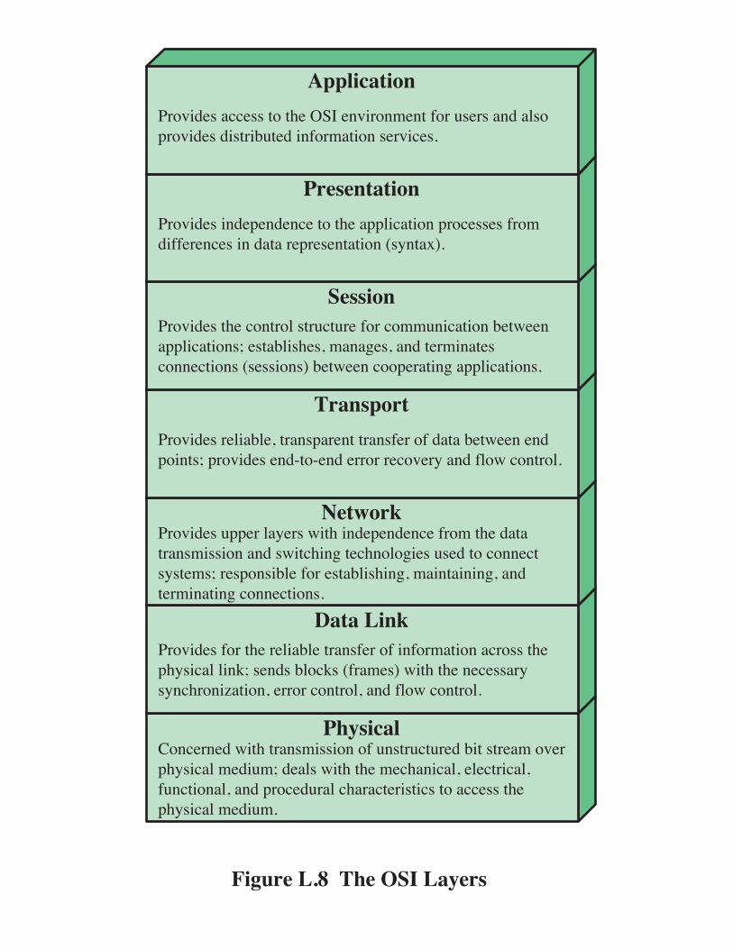
framework for developing protocol standards. The OSI model consists of seven layers:
• Application
• Presentation
• Session
• Transport
1 ISO is not an acronym (in which case it would be IOS), but a word, derived from the Greek
isos, meaning equal.
L-21
• Network
• Data link
• Physical
Figure L.8 illustrates the OSI model and provides a brief definition of the functions performed at
each layer. The intent of the OSI model is that protocols be developed to perform the functions
of each layer.
The designers of OSI assumed that this model and the protocols developed within this
model would come to dominate computer communications, eventually replacing proprietary
protocol implementations and rival multivendor models such as TCP/IP. This has not happened.
Although many useful protocols have been developed in the context of OSI, the overall seven-
layer model has not flourished. Instead, the TCP/IP architecture has come to dominate. There are
a number of reasons for this outcome. Perhaps the most important is that the key TCP/IP
protocols were mature and well tested at a time when similar OSI protocols were in the
development stage. When businesses began to recognize the need for interoperability across
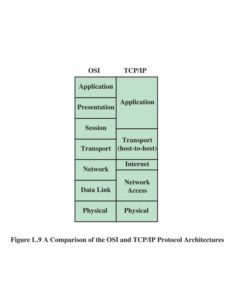
networks, only TCP/IP was available and ready to go. Another reason is that the OSI model is
unnecessarily complex, with seven layers to accomplish what TCP/IP does with fewer layers.
Figure L.9 illustrates the layers of the TCP/IP and OSI architectures, showing roughly the
correspondence in functionality between the two.

!"#$%&'()#"&*+,"-.%/(,
!"#$%&'()#"&*+,"-.%/(,
0%112)(,+#(%)34&".+#"5-1"33+/"3
6(."3-+)5-*(."-#&+)3*"&-,%11+)53
0%172#"&-8
6(/2&"-9:;--<-=(17.(*("5-<&,>(#",#2&"-*%&-6(."-?&+)3*"&
0%172#"&-@
!"#$%&'-+,,"331%52."
0%112)(,+#(%)33"&A(,"-1%52."
6(."-#&+)3*"&+77.(,+#(%)
!"#$%&'-+,,"331%52."
0%112)(,+#(%)33"&A(,"-1%52."
6(."-#&+)3*"&+77.(,+#(%)
0%112)(,+#(%)3)"#$%&'

!"#$%&'()*''+,-'./0'12-'3&.0&%4
56$%7&'-6%8 2&48"/.8"6/'-6%8
,9&7:4$; 1%#&/8'-6"/8&%
5&<$&/7&'=$;>&%
?7:/6@A&0#&;&/8'=$;>&%
BC8"6/4'D'-.00"/#
E&4&%F&0 !A.#4 G"/06@3&.0&%A&/#89
HI"8J K L MN OM
*H'678&84
56$%7&'-6%8 2&48"/.8"6/'-6%8
5&#;&/8'(&/#89 ,9&7:4$;
HI"8J MN OM
L'678&84
P.Q'+,-'3&.0&%
P>Q'12-'3&.0&%

!"#$%&'(
)*+
,+
+-./0123 +-./0123
,+
45+'6 45+'7
+-./0123 +-./0123
4%$8"&9'511%//+&"$"1"3':6
;"/$'5
5<<'=5<<'>
)*+
,+
4%$8"&9'511%//+&"$"1"3':7
;"/$'?
5<<'>5<<'=
4%$8"&9'6 4%$8"&9'7
@3"A23'0B$%&B%$2CC&%//
6 7 7 D EF
G#AB%$8"&9'2$$21-H%B$<"0B$'2CC&%//
I"J0123'1"BB%1$0"BK%LJLM'N0&$#23'10&1#0$O
I"J0123'1"BB%1$0"BK)*+'1"BB%1$0"BO
+"&$'
P0J#&%'ILF'')*+Q,+'*"B1%<$/

!"#$%&'('
)*+,#'&#$
-+,#'&#$
.#(/0$1,#'&#$
233456'(50789(#%"($#':
)*+"#;:#7(
-+&'(';$':
.#(/0$1<4#=#43'61#(
>5;?$#%@AB%%+$0(0604%C'('%!75("%D+C!"E%57%(,#%)*+F-+%2$6,5(#6(?$#

!"#$%&'($)*"+*,
!-#$%&'.$)*"+*,
/012,*$345$$%&$)*"+*,6
7*,6089 :; <=>%)3 ?8@"A$3*91@B
%+*9@0C0D"@089 /A"16 /,"1E*9@$FCC6*@
?0E*$@8$30'* &,8@8D8A )*"+*,$=B*DG62E
FH@0896$I$&"++091
;82,D*$J++,*66
:*6@09"@089$J++,*66
KL0@M ( N O. OP QORK$8D@*@6
O(
7*,6089 :;
:;$S$:0CC*,*9@0"@*+$6*,'0D*6$C0*A+<=>$S$<THA0D0@$D891*6@089$98@0C0D"@089$C0*A+
!"#$%&'($&)*+,#&-./01!&2,$345&6$7$&2"78$739:;"6;&<5&#($&'9=$&"2&.$7>,?$&2,$34&,;&#($&@A>B($<4$7&<;4&#($&'7<22,?&13<55&2,$34&,;&#($&@A>C($<4$7D
<=> /A8U$3"-*A
&"VA8"+$3*91@B >*T@$)*"+*, )8H$30E0@
;82,D*$J++,*66
:*6@09"@089$J++,*66
KL0@M ( OK OR O. R( QO
(K$8D@*@6

!"#$%&"#$'(
)'*+,-,'-)'*+,%.*+/
0'1,2(%30'1,2(%4
!"#!"#
5+6%789,2:%;5+6%789,2:%<
=>89*?@.
A"B
!!B
C=
=>89*?@.
A"B
!!B
C=
=>89*?@.=>89*?@.
A"B
!!B
C=
=>89*?@.
DB=
")).*-?@,*'+
=>89*?@.
A"B
!!B
C=
DB=
")).*-?@,*'+
E*F1(2%!GH%%B'+I*F1(@,*'+%I'(%DB=JC=%5K@:).2% %

!"#$%&'()'*
+,-./0.&,-,-12,34%&'()'*
5'4123(12,3%,-12,34&'()'*
67"%&'()'*
8,9123:%&'()'*
;--<2=(12,3%)(1(
>*(:?'31%&'()'*
>2:9*'%@AB%%%!"#$%"(=C'1%D21&%EF1'342,3%+'()'*4G=,31(2323:%(%67"%H':?'31I
%%%%%%%%%%%%%%%%%J%K'F1%+'()'*%L2'<)
M=1'14N
OP
Q(*2(/<'
Q(*2(/<'
R
Q(*2(/<'
Q(*2(/<'
SP%G,-12,3(<%#(*2(/<'%-(*1I
T(3)(1,*0!"#$%&'()'*
M-12,3(<'F1'342,3&'()'*4
!"#$-(=C'1/,)0
!""#$%&'$()
*+,-,)'&'$()
.,--$()
/+&)-"(+'
0,'1(+2
3&'&45$)2
*67-$%&#!"#$%&#%'()*+,(+&-#./*..*"#("0(1#.+&1$+1&%'(2*+(.+&%-/("3%&4,5.*$-6(/%'*1/7('%-6.()*+,(+,%(/%$,-#*$-68(%6%$+&*$-6801#$+*"#-68(-#'(4&"$%'1&-6($,-&-$+%&*.+*$.(+"(-$$%..(+,%4,5.*$-6(/%'*1/9
:&"3*'%.(0"&(+,%(&%6*-26%(+&-#.0%&("0(*#0"&/-+*"#(-$&"..(+,%4,5.*$-6(6*#;7(.%#'.(26"$;.(<0&-/%.=()*+,(+,%(#%$%..-&5.5#$,&"#*>-+*"#8(%&&"&($"#+&"68(-#'(06")($"#+&"69
:&"3*'%.(144%&(6-5%&.()*+,(*#'%4%#'%#$%(0&"/(+,%('-+-+&-#./*..*"#(-#'(.)*+$,*#?(+%$,#"6"?*%.(1.%'(+"($"##%$+.5.+%/.7(&%.4"#.*26%(0"&(%.+-26*.,*#?8(/-*#+-*#*#?8(-#'+%&/*#-+*#?($"##%$+*"#.9
:&"3*'%.(&%6*-26%8(+&-#.4-&%#+(+&-#.0%&("0('-+-(2%+)%%#(%#'4"*#+.7(4&"3*'%.(%#'@+"@%#'(%&&"&(&%$"3%&5(-#'(06")($"#+&"69
:&"3*'%.(+,%($"#+&"6(.+&1$+1&%(0"&($"//1#*$-+*"#(2%+)%%#-446*$-+*"#.7(%.+-26*.,%.8(/-#-?%.8(-#'(+%&/*#-+%.$"##%$+*"#.(<.%..*"#.=(2%+)%%#($""4%&-+*#?(-446*$-+*"#.9
:&"3*'%.(*#'%4%#'%#$%(+"(+,%(-446*$-+*"#(4&"$%..%.(0&"/'*00%&%#$%.(*#('-+-(&%4&%.%#+-+*"#(<.5#+-A=9
:&"3*'%.(-$$%..(+"(+,%(BCD(%#3*&"#/%#+(0"&(1.%&.(-#'(-6."4&"3*'%.('*.+&*21+%'(*#0"&/-+*"#(.%&3*$%.9
8$9:+,45;<44/6,4=.>45&7,+-
!"#$%&'()*'+',-./0%"1-2'-3'45&'678'029':,;<8;';%-4-=->'+%=5"4&=4$%&1
;5?1"=0>'
@&4A-%B+==&11
824&%2&4
+//>"=04"-2
:%021/-%4C5-14D4-D5-14E
:,;<8;
+//>"=04"-2
;%&1&2404"-2
7&11"-2
:%021/-%4
@&4A-%B
F040'("2B
;5?1"=0>'
678