appendix h – mine subsidence assessment
TRANSCRIPT

GHD | Report for Hunter Water Corporation - Belmont Drought Response Desalination Plant, 2219573
Appendix H – Mine Subsidence Assessment

29 June 2020
Hunter Water Corporation
PO Box 5171
HRMC NSW 2310
Our ref: 2219573-18541 Your ref:
Drought Response Desalination Plant
Mine Subsidence Desktop Assessment - Desalination Plant Site, Seawater Pump
Station and Direct Ocean Intake
1 Introduction
This letter report provides the findings of a mine subsidence desktop assessment for the drought
response desalination plant site, seawater pump station and direct ocean intake alignment. Discussion
relating to subsidence associated risk and possible mitigation measures are also provided.
The above site is not within a declared mine subsidence district, despite being undermined by
abandoned workings in the Borehole and Victoria Tunnel coal seams. Subsidence Advisory NSW (SA
NSW) is not an integrated approval authority for development in this area. The related project for the
construction of the northern water pipeline alignment is within a mine subsidence district and will be
addressed separately through the approval process for that project.
The purpose of this letter is to identify the anticipated risks posed by underground mine workings to the
proposed water treatment process plant, seawater pump station and direct ocean intake structures and
provide a recommendation for mitigation measures based on the desktop review. The letter will be used
to support the EIS Amendment Report for the project.
1.1 Limitations
This report has been prepared by GHD for Hunter Water Corporation and may only be used and relied
on by Hunter Water Corporation for the purpose agreed between GHD and the Hunter Water Corporation
as set out in Section 1 of this report.
GHD otherwise disclaims responsibility to any person other than Hunter Water Corporation arising in
connection with this report. GHD also excludes implied warranties and conditions, to the extent legally
permissible.
The services undertaken by GHD in connection with preparing this report were limited to those
specifically detailed in the report and are subject to the scope limitations set out in the report.
GHD has prepared this report on the basis of information provided by Hunter Water Corporation and
others who provided information to GHD (including Government authorities), which GHD has not
independently verified or checked beyond the agreed scope of work. GHD does not accept liability in
connection with such unverified information, including errors and omissions in the report which were
caused by errors or omissions in that information.

2 2219573-LET_Mine Subsidence Desktop.docx
2 Methodology
The desktop review was completed with reference to record tracings (mine plans) and a PhD thesis of
subsidence relating to pillar extraction and longwall mining (Kapp, William Arthur 19841).
Record tracings (RTs) for John Darling Colliery (RT270 and RT270A) were obtained from the NSW
Department of Planning, Industry and Environment and overlayed (approximately) on geospatial
imagery. The RTs include depictions of the extent and method of mining, location of shafts, surface
boreholes and survey stations, and geological commentary (i.e. dykes, areas of ‘want’ in the coal seam
and geological faults). RTs often include a coordinate grid and seam structural contours in various
formats, depending on the age of the plan. Limited surface features are also often included with roads,
portion boundaries and water bodies shown.
The proposed design layout of the desalination plant, seawater pump station and direct ocean intake
(Figure 1) as well as construction methods detailed in the memo “Belmont Desalination plant – Intake
construction options” (WSP, 25 Nov 2019) were used to inform the review and subsequent discussion.
The geotechnical investigation report (GHD, 2018, Belmont Temporary Desalination Design -
Geotechnical Investigation Report, Doc. 50411) provided information about subsurface conditions.
1 Mine subsidence and strata control in the Newcastle district of the northern coalfield New South Wales, Doctor of Philosophy
thesis, Department of Civil and Mining Engineering, University of Wollongong, 1984, Appendix B, Study 9.

"J
Stormwaterbasin
Indicative constructioncompound andlaydown area
Seawaterpump station
Brine pumpstation
Indicativeintake pipeline
Indicative intakestructure location
Water treatmentprocess plant
Power connection
Existing WWTWocean outfall
Ocean
ParkRoad
BELMONTLAGOON
Figure 1
0 60 120 180 240
Metres
Project No.Revision No. 0
22-19573
Date 29/06/2020
Hunter Water CorporationBelmont Drought Response Desalination Plant
Mine Subsidence Desktop Assessment
Map Projection: Transverse MercatorHorizontal Datum: GDA 1994Grid: GDA 1994 MGA Zone 56
Paper Size ISO A4
oData source: HWC: Aerial Imagery, Existing outfall: 2019; LPI: DTDB / DCDB, 2017; public_NSW_Imagery: © Department of Customer Service 2020. Created by: fmackayG:\22\19573\Design\04 Deliverables\02 Other\2219573_AR_MSDA_0.aprx\2219573_MSDA001_TheProject_0
Print date: 29 Jun 2020 - 10:10
Legend
Onshore project area
Indicative offshore projectarea
No-go area
Drought responsedesalination plant indicativelayout
Brine pump station
Indicative constructioncompound and laydownarea
Seawater pump station
Stormwater basin
"JIndicative intake structurelocation
Power connection
Indicative intake pipeline
Existing WWTW oceanoutfall
The Amended Project
4 2219573-LET_Mine Subsidence Desktop.docx
3 Subsurface profile
A generalised subsurface profile of the desalination plant and direct ocean intake site is presented in
Table 1. This is based on the 2018 geotechnical investigation report by GHD, geological sections from
Kapp (1984) and typical strata shown on the RTs.
Table 1 Subsurface profile for the direct ocean intake and desalination plant site
Approximate depth below ground
Unit
Surface to 50 m Alluvium, comprising sand to around 20-30 m, over estuarine clay.
50 m to 130 m Charlestown Conglomerate.
130 m to > 280 m Undifferentiated Sedimentary Bedrock, comprising sandstone, shale, claystone and coal seam
210 m
280 m
Victoria Tunnel coal seam
Borehole coal seam
4 Mining at the site
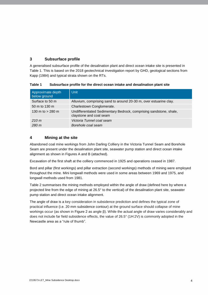
Abandoned coal mine workings from John Darling Colliery in the Victoria Tunnel Seam and Borehole
Seam are present under the desalination plant site, seawater pump station and direct ocean intake
alignment as shown in Figures A and B (attached).
Excavation of the first shaft at the colliery commenced in 1925 and operations ceased in 1987.
Bord and pillar (first workings) and pillar extraction (second workings) methods of mining were employed
throughout the mine. Mini longwall methods were used in some areas between 1969 and 1975, and
longwall methods used from 1981.
Table 2 summarises the mining methods employed within the angle of draw (defined here by where a
projected line from the edge of mining at 26.5° to the vertical) of the desalination plant site, seawater
pump station and direct ocean intake alignment.
The angle of draw is a key consideration in subsidence prediction and defines the typical zone of
practical influence (i.e. 20 mm subsidence contour) at the ground surface should collapse of mine
workings occur (as shown in Figure 2 as angle β). While the actual angle of draw varies considerably and
does not include far field subsidence effects, the value of 26.5° (1H:2V) is commonly adopted in the
Newcastle area as a “rule of thumb”.

5 2219573-LET_Mine Subsidence Desktop.docx
Figure 2 Types of mine subsidence (Knott and Bruyn)
Table 2 Mining methods within angle of draw of plant, seawater pump station and intake
alignment
Approximate depth below ground
Coal seam Mining method Location
210 m Victoria Tunnel Second workings
c. 1973 to 1975
Within the angle of draw (50 – 105 m) from plant, seawater pump station and first 60 m of intake alignment.
Longwall
c. 1981 to 1987
Underlying and within the angle of draw of plant, seawater pump station and intake alignment.
280 m Borehole Longwall
c. 1982 to 1987
Underlying and within the angle of draw of plant, seawater pump station and intake alignment.
The Victoria Tunnel longwall panel shown on Figure A (Appendix A) overlies two Borehole Seam
longwall panels, all of which underlie and are within the angle of draw of the plant, seawater pump station
and intake alignment.

6 2219573-LET_Mine Subsidence Desktop.docx
5 Discussion
For longwall panels, we anticipate that goafing (collapse of the roof above the longwall panels) occurred
progressively during mining as the support chocks and face advanced. A lack of progressive roof
collapse is a very dangerous situation for underground mining personnel as air blasts result when
collapse finally does occur. Given the characteristics of the strata above the mined seam, such
progressive collapse is likely to have occurred reliably and the resulting surface subsidence completed
within a few months following mining.
Goafing above the mined panel and subsidence of the overburden strata results in disturbance to the
strata in the form of cracking, bedding separations and sagging around the collapsed “goaf” zone. The
characteristics of this disturbance depend largely on the nature of the overburden strata. In the case of
longwall mining in the Borehole Seam, it is almost certain that pre-existing workings in the Victoria
Tunnel Seam were effected. The effects are likely to include shearing through remaining coal pillars,
reducing their strength and hence increasing their likelihood of failure.
Large areas of second workings (pillar extraction) also usually collapse and are marked on record
tracings as “goafed”. They are sealed off (to maintain ventilation in operational areas of the mine) and
usually not re-entered. However, in many cases, small areas of secondary workings with short spans of
more competent strata between supporting pillars or unmined coal will remain standing for several
decades. This is particularly so where remnant pillars “stooks” exist. Such stooks are often not depicted
on record tracings. As such, complete collapse (“goafing”) of areas of secondary pillar extraction,
particularly with short roof spans, is not reliably known despite such areas being shown as “goafed” on
record tracings. Consequently the potential for future collapse and subsidence cannot be discounted
without further knowledge of the mine, subsidence survey data or borehole investigations post-mining.
Fortunately the ground surface above the area of second workings noted in Table 2 was monitored and
subsidence recorded in the PhD thesis (Kapp, 1984). A surface survey line was monitored between 1972
and 1975 to record subsidence due to extraction of a number of mini wall panels as well as the area of
pillar extraction in the VT Seam. Maximum subsidence (Smax) of 600 mm was recorded (compared to a
predicted Smax of 690 mm). Subsidence monitoring continued until 1980 and showed no further notable
movement. After 1980, longwall mining in the Victoria Tunnel Seam and underlying Borehole Seam was
undertaken and additional subsidence would have occurred.
Note: JD109 located above short wall, JD145 located near southern edge of pillar extraction
Figure 3 Subsidence monitoring (Kapp, 1984)

7 2219573-LET_Mine Subsidence Desktop.docx
Kapp (1984) noted the subsidence profile was smooth with no unaccounted irregularities, indicating full
roof convergence (collapse) occurred over the area of secondary workings. Calculation of the geometric
relationship (size, depth and height) of the pillars indicated that surrounding smaller pillars would have
been crushed and larger pillars would not have remained stable (Kapp, 1983, pp B-86). Based on the
above, we anticipate that goafing of the second workings did occur and further roof convergence
(crushing of pillars due to abutment loading) surrounding the area of secondary workings also occurred.
While considered very unlikely based on the information reviewed, there is the possibility of future
residual subsidence due to crushing of chain and development pillars between panels (abutment loading
and pillar degradation). More likely is that stress redistribution through goaf areas and stress reduction
due to mine inundation (flooding) has occurred reducing stresses on pillars to achieve a “long term
stable” situation.
The magnitude and profile of subsidence at the ground surface and near surface would be mitigated by a
thick conglomerate unit (Charlestown Conglomerate) and approximately 50 m thick alluvial soil unit which
would both act to reduce and distribute (‘smooth out’) any ground surface subsidence. It is unlikely the
effects of such residual subsidence would be noticeable without the aid of high accuracy ground surveys
before and during subsidence.
Multi-bean sonar bathymetry and sub-bottom profiling (sparker) over a 1 km x 2 km area was collected in
October 2019 (GHD letter dated 19 December 2019). Bathymetry showed no patterns that could be
attributed to longwall mine subsidence troughs and we expect any such troughs would have been infilled
with sand. Bedrock level isopachs show lower areas that could be attributed to subsidence however,
their relief relative to areas of bedrock high are in the order of up to 10 to 25 m. These are natural
erosional features. A clear pattern representing the longwall panels beneath is not evident. This is
primarily expected to be due to the degree of natural bedrock relief that obscures shallower trough
subsidence depressions.
6 Risk and mitigation measures
Based on the proposed layout of the desalination plant, seawater pump station and direct ocean intake
alignment, the construction methods for the intake structure, as well as the above desktop review, we
anticipate the likelihood is:
1) Very low that future mine subsidence would occur
2) Very low that should subsidence occur, it would adversely impact the proposed development
A conceivable worst-case consequence of subsidence is differential movement of foundations or pipes in
the plant or rotation of the seawater pump station, putting it slightly out of vertical alignment and resulting
in rotation at the well/pipework connection. A very rigid connection would see such rotation result in
additional stress at the connection.
We recommend HWC consider the assessed very low likelihood of residual subsidence occurring
combined with the very low likelihood that such subsidence would be of a magnitude to adversely impact
the proposed development. If the associated risk is acceptable to HWC, no further assessment or design
consideration would be recommended.

8 2219573-LET_Mine Subsidence Desktop.docx
Alternatively, if the risk is considered unacceptable, detailed design could consider options to provide a
less rigid connection (given that this is understood to be common practice for the use of flexible pipe
connections in such designs). If required, the magnitude of seawater pump station tilt to accommodate in
the design could be estimated from a hypothetical subsidence profile approximated by an exponential
function that is derived in part from the subsidence data provided in Kapp 1984.
Sincerely
GHD
Joanna Sylvester
Senior Engineering Geologist
+61 2 49799063
Attachment: A – Figures

Appendix A
Figures

©
Figure ALevel 3, GHD Tower, 24 Honeysuckle Drive Newcastle NSW 2300 T 61 2 49 79 9999 F 61 2 49 79 9988 Web www.ghd.com.au
job noHunter Water CorporationBelmont Desalination PlantHistoric Underground Mining – Victoria Tunnel Seam workings (approx.)
2219573
Note: The extent of workings shown is approximate only and based on the RTs for 270 and 270A.
©
Figure BLevel 3, GHD Tower, 24 Honeysuckle Drive Newcastle NSW 2300 T 61 2 49 79 9999 F 61 2 49 79 9988 Web www.ghd.com.au
job noHunter Water CorporationBelmont Desalination PlantHistoric Underground Mining – Borehole Seam workings (approx.)
2219573
‐‐‐‐ Area of interest (based on angle of draw)Note: The extent of workings shown is approximate only and based on the RTs for 270 and 270ANote: The extent of workings shown is approximate only and based on the RTs for 270 and 270A