appendix e additional design requirements - seattlepan/documents/... · e-4 city of seattle...
TRANSCRIPT

April 2014 Review Draft
APPENDIX E
Additional Design Requirements


April 2014 Review Draft
City of Seattle Stormwater Manual E-1
Appendix E includes additional design requirements for the following:
Flow control structures (Section E-1)
Flow splitters (Section E-2)
Flow spreaders (Section E-3)
Level spreaders (Section E-4)
Pipe slope drains (Section E-5)
Outlet protection (Section E-6)
Facility liners (Section E-7)
Geotextiles (Section E-8)
Plant Lists for Biofiltration Swales, Sand Filters, and Wet Ponds (Section E-9)

April 2014 Review Draft
City of Seattle Stormwater Manual E-3
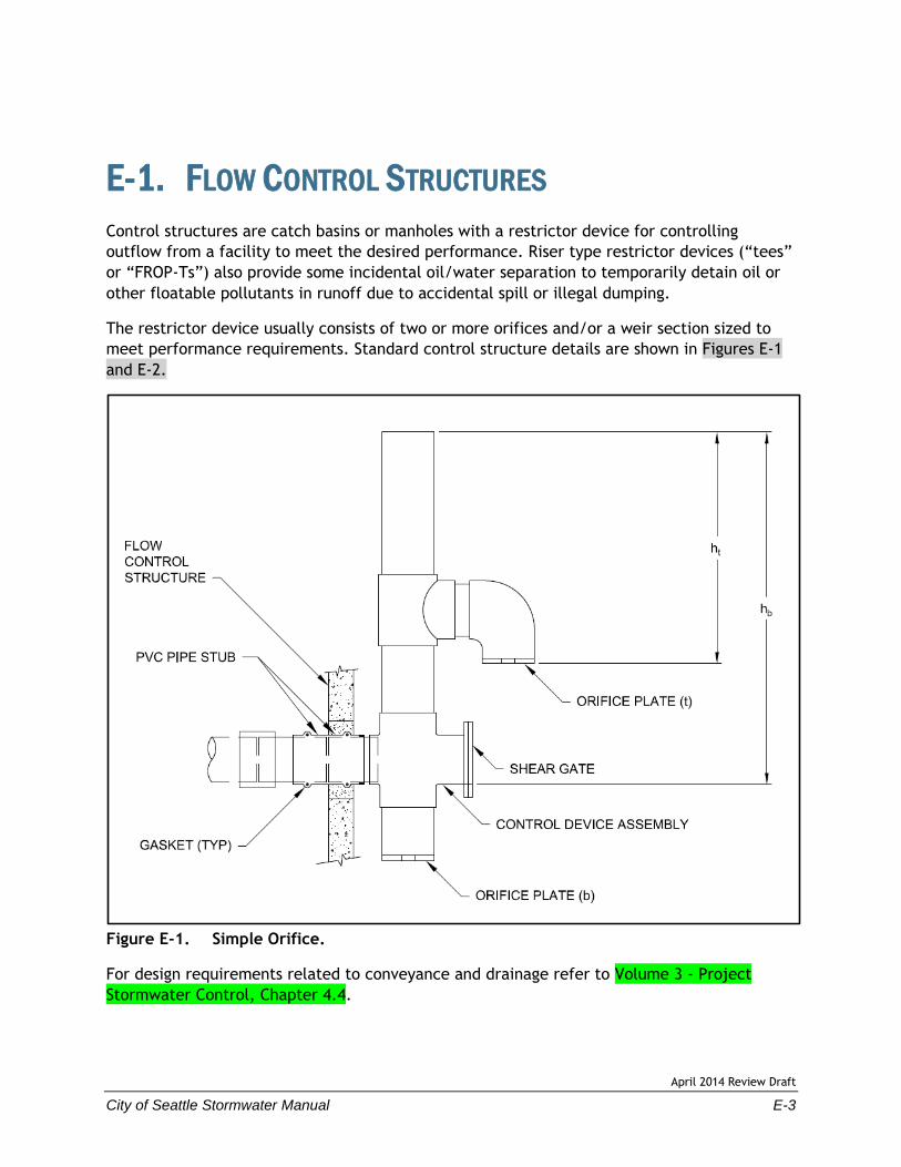
E-1. FLOW CONTROL STRUCTURES
Control structures are catch basins or manholes with a restrictor device for controlling
outflow from a facility to meet the desired performance. Riser type restrictor devices (“tees”
or “FROP-Ts”) also provide some incidental oil/water separation to temporarily detain oil or
other floatable pollutants in runoff due to accidental spill or illegal dumping.
The restrictor device usually consists of two or more orifices and/or a weir section sized to
meet performance requirements. Standard control structure details are shown in Figures E-1
and E-2.
Figure E-1. Simple Orifice.
For design requirements related to conveyance and drainage refer to Volume 3 - Project
Stormwater Control, Chapter 4.4.
April 2014 Review Draft
E-4 City of Seattle Stormwater Manual
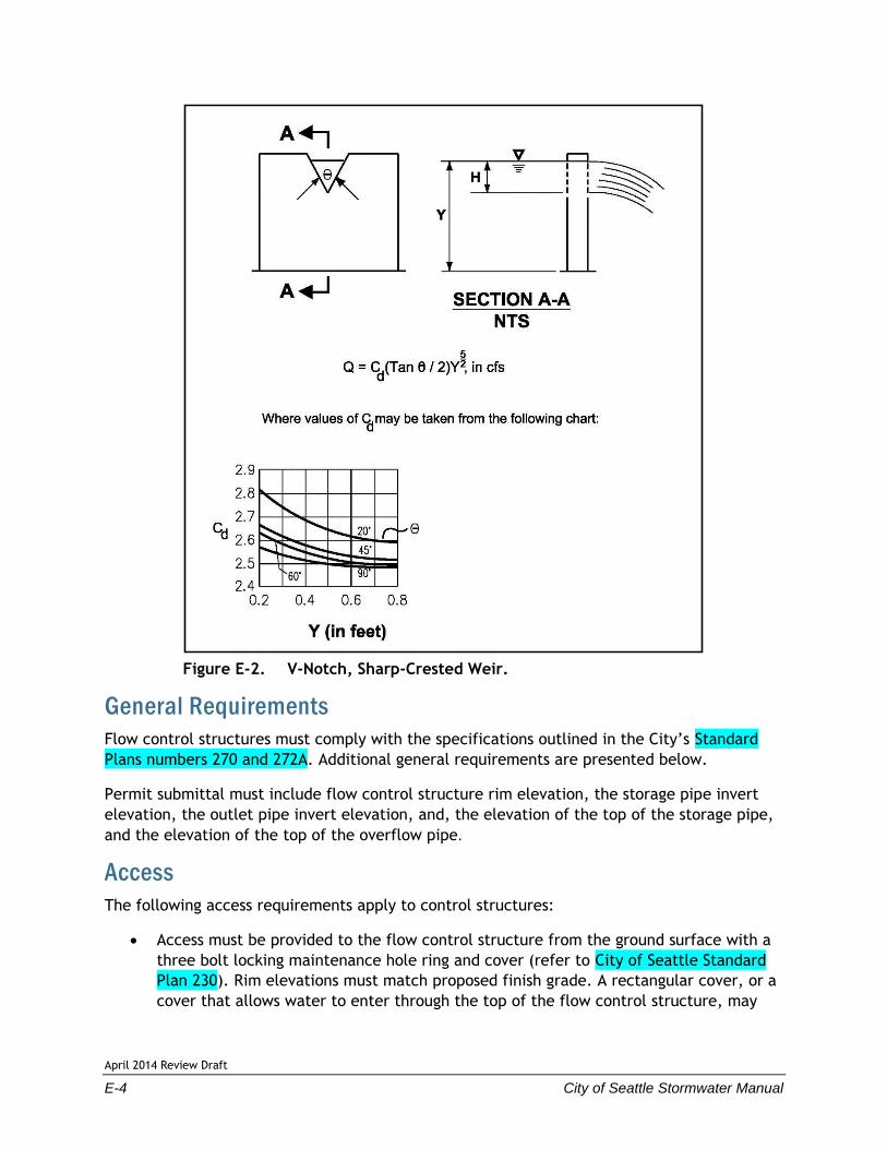
Figure E-2. V-Notch, Sharp-Crested Weir.
General Requirements
Flow control structures must comply with the specifications outlined in the City’s Standard
Plans numbers 270 and 272A. Additional general requirements are presented below.
Permit submittal must include flow control structure rim elevation, the storage pipe invert
elevation, the outlet pipe invert elevation, and, the elevation of the top of the storage pipe,
and the elevation of the top of the overflow pipe.
Access
The following access requirements apply to control structures:
Access must be provided to the flow control structure from the ground surface with a
three bolt locking maintenance hole ring and cover (refer to City of Seattle Standard
Plan 230). Rim elevations must match proposed finish grade. A rectangular cover, or a
cover that allows water to enter through the top of the flow control structure, may

April 2014 Review Draft
City of Seattle Stormwater Manual E-5
not be used. The ring and cover must be set so the flow control device or the ladder is
visible at the edge of the access opening.
The inside diameter of the flow control structure must be at least 4 feet to allow
maintenance and repair access, and to accommodate stormwater overflow.
Manholes and catch basins must meet the OSHA and WISHA confined space
requirements, which include, but are not limited to, clearly marking entrances to
confined space areas. This may be accomplished by hanging a removable sign in the
access riser, just under the access lid.
The flow control device must be PVC, not Corrugated Metal Pipe (CMP). The mounting
straps and the outlet adapter must be installed in a manner that will make the flow
control device easily removable for maintenance, repair, or replacement. The flow
control device must be designed and located under the maintenance hole ring and
cover for inspection from the surface. The outlet pipe adapter may be a plastic,
bell-end pipe or a plastic coupling with rubber gaskets. The outside of the pipe or
coupling must be sanded, epoxy coated, and sand impacted to bond with the flow
control structure. This preparation must be done by the manufacturer or supplier, not
in the field.
Information Plate
A brass or stainless steel plate must be permanently attached inside each control structure
with the following information engraved on the plate:
Name and file number of project
Name and company of 1) developer, 2) engineer, and 3) contractor
Date constructed
Date of manual used for design
Flow performance criteria
Release mechanism size, type, and invert elevation
List of stage, discharge, and volume at 1-foot increments
Elevation of overflow
Required frequency of maintenance
Design Criteria
Multiple Orifice Restrictor
In most cases, control structures need only two orifices: one at the bottom and one near
the top of the riser, although additional orifices may best utilize detention storage volume.
Several orifices may be located at the same elevation if necessary to meet performance
requirements.
Design requirements for multiple orifice flow restrictors are presented below.

April 2014 Review Draft
E-6 City of Seattle Stormwater Manual
The minimum allowable orifice diameter is 0.5 inches for below ground outlets and
0.25 inches for aboveground outlets. In some instances, a 0.5-inch bottom orifice will
be too large to meet target release rates, even with minimal head. In these cases, the
live storage depth need not be reduced to less than 3 feet in an attempt to meet the
performance standards. Also, under such circumstances, flow-throttling devices may
be a feasible option. These devices will throttle flows while maintaining a plug-
resistant opening.
Orifices may be constructed on a tee section as shown in City of Seattle Standard
Plan 270 or on a baffle.
In some cases, performance requirements may require the top orifice/elbow to be
located too high on the riser to be physically constructed (e.g., a 13-inch-diameter
orifice positioned 0.5 feet from the top of the riser). In these cases, a notch weir in
the riser pipe may be used to meet performance requirements.
Consideration must be given to the backwater effect of water surface elevations in the
downstream conveyance system. High tailwater elevations may affect performance of
the restrictor system and reduce live storage volumes. Backwater calculations may be
required.
Riser and Weir Restrictor
Design requirements for multiple orifice flow restrictors are presented below.
Properly designed weirs may be used as flow restrictors. However, they must be
designed to provide for primary overflow of the developed 100-year peak flow
discharging to the detention facility.
The combined orifice and riser (or weir) overflow may be used to meet performance
requirements; however, the design must still provide for primary overflow of the
developed 100-year peak flow assuming all orifices are plugged. Figure E-3 can be used
to calculate the head in feet above a riser of given diameter and flow.
Flow Control Device Sizing
Orifices
Flow through orifice plates in the standard tee section or turn-down elbow may be
approximated by the general equation:
gh2A CQ
where Q = flow (cfs)
C = coefficient of discharge (0.62 for plate orifice)
A = area of orifice (ft2)
h = hydraulic head (ft)
g = gravity (32.2 ft/sec2)
Figure E-1 illustrates this simplified application of the orifice equation.

April 2014 Review Draft
City of Seattle Stormwater Manual E-7
Figure E-3. Riser Inflow Curves.
The diameter of the orifice is calculated from the flow. The orifice equation is often useful
when expressed as the orifice diameter in inches.
h
Qd
88.36
where d = orifice diameter (inches)
Q = flow (cfs)
h = hydraulic head (ft)

April 2014 Review Draft
E-8 City of Seattle Stormwater Manual
The combined orifice and riser (or weir) overflow may be used to meet performance
requirements; however, the design must still provide for primary overflow of the developed
100-year peak flow assuming all orifices are plugged. Figure E-3 can be used to calculate the
head in feet above a riser of given diameter and flow.
Riser Overflow
The nomograph in Figure E-3 can be used to determine the head (in feet) above a riser of
given diameter and for a given flow (usually the 100-year peak flow for developed
conditions).

April 2014 Review Draft
City of Seattle Stormwater Manual E-9
E-2. FLOW SPLITTERS
Many water quality facilities can be designed as flow-through or on-line systems with flows
above the water quality design flow simply passing through the facility at a lower pollutant
removal efficiency. However, it is sometimes desirable to restrict flows to water quality
treatment facilities and bypass the remaining higher flows around them (i.e., offline
facilities). This can be accomplished by splitting flows in excess of the water quality design
flow upstream of the facility and diverting higher flows to a bypass pipe or channel. The
bypass typically enters a detention pond or the downstream receiving drainage system,
depending on applicable flow control requirements. In most cases, it is a designer’s choice
whether water quality facilities are designed as on-line or offline; an exception is oil/water
separators and sand filters, which must be designed offline.
A crucial factor in designing flow splitters is to ensure that low flows are delivered to the
treatment facility up to the water quality design flow rate. Above this rate, additional flows
are diverted to the bypass system with minimal increase in head at the flow splitter structure
to avoid surcharging the water quality treatment facility under high flow conditions.
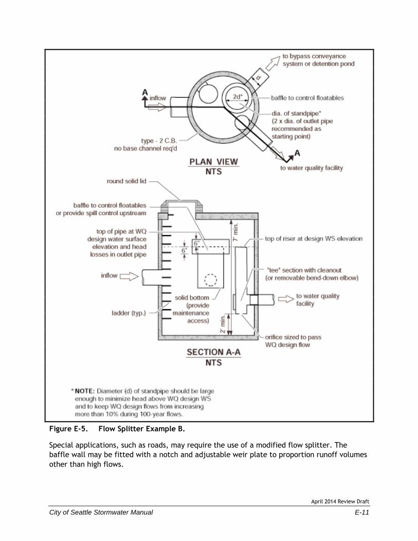
Flow splitters are typically manholes or vaults with concrete baffles. In place of baffles,
the splitter mechanism may be a half tee section with a solid top and an orifice in the bottom
of the tee section. A full tee option may also be used as described below under General
Design Criteria. Two examples for manhole-based flow splitters are shown in Figure E-4
and Figure E-5. Other equivalent designs that achieve the result of splitting low flows and
diverting higher flows around the facility may also be acceptable.
General Design Criteria
A flow splitter must be designed to deliver the water quality design flow rate specified in this
volume to the water quality treatment facility. For the basic size sand filter, which is sized
based on volume, use the water quality design flow rate to design the splitter. For the large
sand filter, use the flow rate that corresponds with treating 95 percent of the runoff volume
predicted by an approved continuous runoff model.
The top of the weir must be located at the water surface for the design flow. Remaining flows
enter the bypass line. Flows modeled using a continuous simulation model must be at a
15-minute time step or less.
The maximum head must be minimized for flow in excess of the water quality design flow.
Specifically, flow to the water quality treatment facility at the 100-year water surface must
not increase the design water quality flow by more than 10 percent.
As an alternative to using a solid top plate in Figure E-5, a full tee section may be used with
the top of the tee at the 100-year water surface. This alternative would route emergency
overflows (if the overflow pipe were plugged) through the water quality treatment facility
rather than generate back up from the maintenance hole.

April 2014 Review Draft
E-10 City of Seattle Stormwater Manual
Figure E-4. Flow Splitter Example A.
April 2014 Review Draft
City of Seattle Stormwater Manual E-11
Figure E-5. Flow Splitter Example B.
Special applications, such as roads, may require the use of a modified flow splitter. The
baffle wall may be fitted with a notch and adjustable weir plate to proportion runoff volumes
other than high flows.
April 2014 Review Draft
E-12 City of Seattle Stormwater Manual
For ponding facilities, backwater effects must be included in designing the height of the
standpipe in the manhole.
Ladder or step and handhold access must be provided. If the baffle wall is higher than
36 inches, two ladders, one to either side of the wall, must be used. The minimum clearance
between the top of the baffle wall and the bottom of the manhole cover must be 4 feet;
otherwise, dual access points should be provided.
Materials
The splitter baffle may be installed in a Type 2 manhole or vault.
The baffle wall must be made of reinforced concrete or another suitable material
resistant to corrosion, and have a minimum 4-inch thickness.
All metal parts must be corrosion resistant. Examples of preferred materials include
aluminum, stainless steel, and plastic. Zinc and galvanized materials are prohibited
because of aquatic toxicity. Painted metal parts should not be used because of poor
longevity.
April 2014 Review Draft
City of Seattle Stormwater Manual E-13
E-3. FLOW SPREADERS
Flow spreaders uniformly spread flows across the inflow portion of non-infiltrating BMPs (e.g.,
sand filter, biofiltration swale, or filter strip). There are five flow spreader options presented
in this section:
Option A – Anchored plate
Option B – Concrete sump box
Option C – Notched curb spreader
Option D – Through-curb ports
Option E – Interrupted curb
Options A through C can be used for spreading flows that are concentrated. Any one of these
options can be used when spreading is required by the facility design criteria. Options A
through C can also be used for unconcentrated flows, and in some cases must be used, such as
to correct for moderate grade changes along a filter strip.
Options D and E are only for flows that are already unconcentrated and enter a filter strip or
continuous inflow biofiltration swale. Other flow spreader options are possible with prior
approval by the Director.
General Design Criteria
Where flow enters the flow spreader through a pipe, it is recommended that the pipe be
submerged to the extent practical to dissipate energy as much as possible. For higher inflows
(greater than 5 cfs for the 100-year storm), a Type 1 catch basin should be positioned in the
spreader and the inflow pipe should enter the catch basin with flows exiting through the top
grate. The top of the grate should be lower than the level spreader plate, or if a notched
spreader is used, lower than the bottom of the v-notches.
Option A – Anchored Plate
An anchored plate flow spreader must be preceded by a sump having a minimum depth
of 8 inches and minimum width of 24 inches. If not otherwise stabilized, the sump area
must be lined to reduce erosion and to provide energy dissipation.
The top surface of the flow spreader plate must be level, projecting a minimum
of 2 inches above the ground surface of the water quality treatment facility, or
v-notched with notches 6 to 10 inches on center and 1 to 6 inches deep (use shallower
notches with closer spacing). Alternative designs may also be considered.
A flow spreader plate must extend horizontally beyond the bottom width of the
facility to prevent water from eroding the side slope. The horizontal extent should be

April 2014 Review Draft
E-14 City of Seattle Stormwater Manual
such that the bank is protected for all flows up to the 100-year flow, or the maximum
flow that will enter the water quality treatment facility.
Flow spreader plates must be securely fixed in place
Flow spreader plates may be made of either wood, metal, fiberglass reinforced
plastic, or other durable material. If wood, pressure treated 4- by 10-inch lumber or
landscape timbers are acceptable.
Anchor posts must be 4-inch square concrete, tubular stainless steel, or other material
resistant to decay. Refer to the Stormwater Management Manual for Western
Washington Volume V, Figure 4.5.3 for an example of an anchored plate flow
spreader.
Option B – Concrete Sump Box
The wall of the downstream side of a rectangular concrete sump box must extend a
minimum of 2 inches above the treatment bed. This serves as a weir to spread the
flows uniformly across the bed.
The downstream wall of a sump box must have “wing walls” at both ends. Side walls
and returns must be slightly higher than the weir so that erosion of the side slope is
minimized.
Concrete for a sump box can be either cast-in-place or precast, but the bottom of the
sump must be reinforced with wire mesh for cast-in-place sumps.
Sump boxes must be placed over bases that consists of 4 inches of crushed rock,
5/8-inch minus to help assure the sump remains level. Refer to the Stormwater
Management Manual for Western Washington Volume V, Figure 4.5.4 for an example of
a concrete sump box flow spreader.
Option C – Notched Curb Spreader
Notched curb spreader sections must be made of extruded concrete laid side-by-side and
level. Typically, five “teeth” per 4-foot section provide good spacing. The space between
adjacent teeth forms a v-notch.
Option D – Through-Curb Ports
Unconcentrated flows from paved areas entering filter strips or continuous inflow biofiltration
swales can use curb ports or interrupted curbs (Option E) to allow flows to enter the strip or
swale. Curb ports use fabricated openings that allow concrete curbing to be poured or
extruded while still providing an opening through the curb to admit water to the water
quality treatment facility.
Openings in the curb must be at regular intervals but at least every 6 feet (minimum). The
width of each curb port opening must be a minimum of 11 inches. Approximately 15 percent
or more of the curb section length should be in open ports, and no port should discharge more
than about 10 percent of the flow. Refer to the Stormwater Management Manual for Western
Washington Volume V, Figure 4.5.6 for an example of a through-curb port flow spreader.

April 2014 Review Draft
City of Seattle Stormwater Manual E-15
Option E – Interrupted Curb
Interrupted curbs are sections of curb placed to have gaps spaced at regular intervals along
the total width (or length, depending on the facility) of the treatment area. At a minimum,
gaps must be every 6 feet to allow distribution of flows into the treatment facility before
they become too concentrated. The opening must be a minimum of 11 inches. As a general
rule, no opening should discharge more than 10 percent of the overall flow entering the
facility.


April 2014 Review Draft
City of Seattle Stormwater Manual E-17
E-4. LEVEL SPREADERS
Definition
A level spreader is an outlet for dikes and diversions consisting of an excavated depression
constructed at zero grade across a slope and can also be used to distribute water either
entering or exiting a flow control or treatment facility.
Purpose
To convert concentrated runoff to a thin layer of sheet flow, which releases onto a stable
receiving area. For example, an existing vegetated area or a vegetated strip.
Condition Where Practice Applies
To be constructed on undisturbed areas that are stabilized by existing vegetation and where
concentrated flows are anticipated to occur at zero percent grade (Figure E-6).
Figure E-6. Level Spreader Prior to Backfill.
April 2014 Review Draft
E-18 City of Seattle Stormwater Manual
Planning Considerations
If properly constructed, the level spreader will significantly reduce the velocity of
concentrated stormwater and spread it uniformly over a stable undisturbed area.
Particular care must be taken during construction to ensure that the lower lip of the structure
is level and on grade. If there are any depressions in the lip, flow will tend to concentrate at
these points and erosion will occur, resulting in failure of the outlet. This problem may be
avoided by using a grade board or a gravel lip over which the runoff must flow when exiting
the spreader. Regular maintenance is essential for this practice.
Design Criteria
The grade of the pipe and/or ditch for the last 20 feet before entering the level
spreader shall be less than or equal to 1 percent. If the grade is steeper, provide a
flow dissipation device. The grade of the level spreader shall be 0 percent to ensure
uniform spreading of stormwater runoff.
An 8-inch high gravel berm placed across the level lip shall consist of washed crushed
rock, 2 to 4 inch or 3/4 inch to 1.5 inch size.
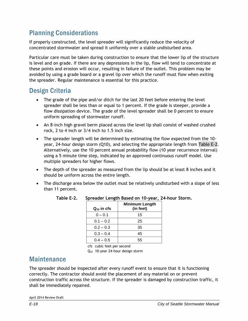
The spreader length will be determined by estimating the flow expected from the 10-
year, 24-hour design storm (Q10), and selecting the appropriate length from Table E-2.
Alternatively, use the 10 percent annual probability flow (10 year recurrence interval)
using a 5 minute time step, indicated by an approved continuous runoff model. Use
multiple spreaders for higher flows.
The depth of the spreader as measured from the lip should be at least 8 inches and it
should be uniform across the entire length.
The discharge area below the outlet must be relatively undisturbed with a slope of less
than 11 percent.
Table E-2. Spreader Length Based on 10-year, 24-hour Storm.
Q10 in cfs Minimum Length
(in feet)
0 – 0.1 15
0.1 – 0.2 25
0.2 – 0.3 35
0.3 – 0.4 45
0.4 – 0.5 55
cfs cubic feet per second
Q10 10-year 24-hour design storm
Maintenance
The spreader should be inspected after every runoff event to ensure that it is functioning
correctly. The contractor should avoid the placement of any material on or prevent
construction traffic across the structure. If the spreader is damaged by construction traffic, it
shall be immediately repaired.

April 2014 Review Draft
City of Seattle Stormwater Manual E-19
E-5. PIPE SLOPE DRAINS
Definition
A slope drain consists of a pipe extending from the top to the bottom of a cut or fill slope and
discharging into a stabilized watercourse or a sediment trapping device or onto a stabilization
area. It can also be used for water discharging from a flow control or treatment facility.
Purpose
To carry concentrated runoff down steep slopes without causing gullies, channel erosion, or
saturation of slide-prone soils (Figure E-7).
Figure E-7. Schematic of a Pipe Slope Drain.
Conditions Where Practice Applies
Conveying runoff down a slope without causing erosion. A permanent measure requires
inclusion in the project drainage plan and must be designed by a Professional Engineer.
On highway projects, pipe slope drains should be used at bridge ends to collect runoff and
pipe it to the base of the fill slopes along bridge approaches.
Planning Considerations
There is often a significant lag between the time a cut or fill slope is completed and the time
a permanent drainage system can be installed. During this period, the slope is usually not
stabilized and is particularly vulnerable to erosion. This situation also occurs on slope

April 2014 Review Draft
E-20 City of Seattle Stormwater Manual
construction that is temporarily delayed before final grade is reached. Temporary slope drains
can provide valuable protection of exposed slopes until permanent drainage structures can be
installed. When used in conjunction with diversion dikes, temporary slope drains can be used
to convey stormwater from the entire drainage area above a slope to the base of the slope
without erosion. It is very important that these temporary structures be installed properly
since their failure will often result in severe gully erosion. The entrance section must be
securely entrenched, all connections must be watertight, and the conduit must be staked
securely.
Additional requirements for steep slopes are included in the Environmentally Critical Area
Ordinance (SMC, Section 25.09.180).
Design Criteria
Permanent slope drains should be designed by an engineer and may have additional
criteria for flow and water quality treatment requirements. Variations or alterations
to the minimum BMP requirements outlined below require an engineer’s approval.
The capacity for temporary drains shall be sufficient to handle a 10-year, 24-hour peak
flow. Alternatively, use the 10 percent annual probability flow (10-year recurrence
interval) using a 5-minute time step, indicated by an approved continuous runoff
model. The hydrologic analysis shall use the existing land cover condition for
predicting flow rates from tributary areas outside the project limits. For tributary
areas on the project site, the analysis shall use the temporary or permanent project
land cover condition, whichever will produce the highest flow rates. If using WWHM,
bare soil areas should be modeled as “landscaped area.” Refer to Appendix F for
additional information on stormwater modeling.
Re-establish cover immediately on areas disturbed by installation.
Ensure that the entrance area is stable and large enough to direct flow into the pipe.
The entrance shall consist of a standard flared end section for culverts 12 inches and
larger with a minimum 6-inch metal toe plate to prevent runoff from undercutting the
pipe inlet. The slope of the entrance shall be at least 3 percent (Figure E-8).
Pipe size should be no greater than 6 inches. Intercept flow frequently by using
multiple pipe slope drains. Multiple pipes should be no closer than 10 feet.
The soil around and under the pipe and entrance section shall be thoroughly
compacted to prevent undercutting.
The flared inlet section shall be securely connected to the slope drain and have
watertight connecting bands.
Slope drain sections shall be securely fastened together and have gasketed watertight
fittings, and be securely anchored into the soil.
Thrust blocks should be installed any time 90 degree bends are utilized. Depending on
size of pipe and flow, these can be constructed with sand bags, straw bales staked in
place, “t” posts and wire, or ecology blocks.
April 2014 Review Draft
City of Seattle Stormwater Manual E-21
Pipe needs to be secured along its full length to prevent movement. This can be done
with steel “t” posts and wire. A post is installed on each side of the pipe and the pipe
is wired to them. This should be done every 10 to 20 feet of pipe length or so,
depending on the size of the pipe and quantity of water diverted.
Earth dikes shall be used to direct runoff into a slope drain. The height of the dike
shall be at least 1 foot higher at all points than the top of the inlet pipe.
Any excavated material shall be placed on the uphill side of trenches, consistent with
safety and space considerations.
The area below the outlet must be stabilized with a riprap apron.
If the pipe slope drain is conveying sediment-laden water, direct all flows into the
sediment trapping facility.
Refer to the City of Seattle Standard Specifications for all material specifications
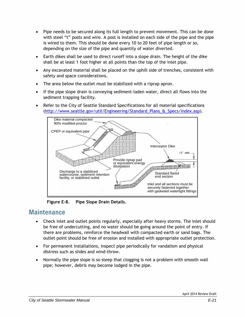
(http://www.seattle.gov/util/Engineering/Standard_Plans_&_Specs/index.asp).
Figure E-8. Pipe Slope Drain Details.
Maintenance
Check inlet and outlet points regularly, especially after heavy storms. The inlet should
be free of undercutting, and no water should be going around the point of entry. If
there are problems, reinforce the headwall with compacted earth or sand bags. The
outlet point should be free of erosion and installed with appropriate outlet protection.
For permanent installations, inspect pipe periodically for vandalism and physical
distress such as slides and wind-throw.
Normally the pipe slope is so steep that clogging is not a problem with smooth wall
pipe; however, debris may become lodged in the pipe.
Dike material compacted90% modified proctor
CPEP or equivalent pipe
Discharge to a stabilizedwatercourse, sediment retentionfacility, or stabilized outlet
Inlet and all sections must besecurely fastened togetherwith gasketed watertight fittings
Provide riprap pador equivalent energydissipation
Interceptor Dike
Standard flaredend section

April 2014 Review Draft
City of Seattle Stormwater Manual E-23
E-6. OUTLET PROTECTION
Definition
Structurally lined aprons or other acceptable energy dissipating devices placed at the outlets
of pipes or paved channel sections.
Purpose
To prevent scour at stormwater outlets, and to minimize the potential for downstream
erosion by reducing the velocity of concentrated stormwater flows.
Condition Where Practice Applies
Outlet protection is required at the outlets of all ponds, pipes, ditches, or other conveyances,
and where runoff is conveyed to a natural or manmade drainage feature such as a stream,
wetland, or ditch.
Planning Considerations
An outfall is defined as a concentrated discharge point that directs collected surface water
flows into an open drainage feature, natural or manmade. These drainage features include
ditches, channels, swales, closed depressions, wetlands, streams, rivers, ponds, lakes, or
other open bodies of water. In nearly every case, the outfall will consist of a pipe discharging
flows from a drainage system, a culvert, or a detention facility.
Design Criteria
Permanent BMPs should be designed by an engineer and may have additional criteria
for flow and water quality treatment requirements. Variations and/or alterations to
the minimum BMP requirements require an engineer’s approval.
Permanent applications may have additional requirements, as specified in Volume 3 -
Project Stormwater Control.
No outfall should be allowed without proper permits and approvals.
The surface water ultimately receiving drainage water at the outlet of a culvert shall
be protected from erosion by rock lining the downstream and extending up the
channel sides above the maximum tail water elevation.
For large pipes (more than 18 inches in diameter), the outlet protection lining of the
channel is lengthened as much as four times the diameter of the culvert.
Standard wing walls, and tapered outlets and paved channels should also be
considered when appropriate for permanent culvert outlet protection.

April 2014 Review Draft
E-24 City of Seattle Stormwater Manual
Organic or synthetic erosion blankets, with or without vegetation, are usually more
effective than rock, cheaper, and easier to install. However, materials can be chosen
using manufacturer product specifications and cross-checked with the City of Seattle
Standard Specifications for erosion control materials Section 9 14.
With low flows, vegetation (including sod) can be effective, riprap outlet protection is
also appropriate in some situations.
For outlets at the base of steep slope pipes (pipe slope greater than 10 percent), an
engineered energy dissipater shall be used with filter fabric or erosion control blankets
under riprap to prevent scour and channel erosion.
Maintenance
Rock may need to be added if sediment builds up in the pore spaces of the outlet pad.
April 2014 Review Draft
City of Seattle Stormwater Manual E-25
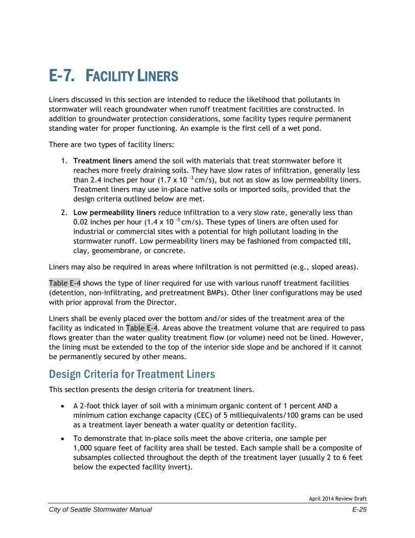
E-7. FACILITY LINERS
Liners discussed in this section are intended to reduce the likelihood that pollutants in
stormwater will reach groundwater when runoff treatment facilities are constructed. In
addition to groundwater protection considerations, some facility types require permanent
standing water for proper functioning. An example is the first cell of a wet pond.
There are two types of facility liners:
1. Treatment liners amend the soil with materials that treat stormwater before it
reaches more freely draining soils. They have slow rates of infiltration, generally less
than 2.4 inches per hour (1.7 x 10 -3 cm/s), but not as slow as low permeability liners.
Treatment liners may use in-place native soils or imported soils, provided that the
design criteria outlined below are met.
2. Low permeability liners reduce infiltration to a very slow rate, generally less than
0.02 inches per hour (1.4 x 10 -5 cm/s). These types of liners are often used for
industrial or commercial sites with a potential for high pollutant loading in the
stormwater runoff. Low permeability liners may be fashioned from compacted till,
clay, geomembrane, or concrete.
Liners may also be required in areas where infiltration is not permitted (e.g., sloped areas).
Table E-4 shows the type of liner required for use with various runoff treatment facilities
(detention, non-infiltrating, and pretreatment BMPs). Other liner configurations may be used
with prior approval from the Director.
Liners shall be evenly placed over the bottom and/or sides of the treatment area of the
facility as indicated in Table E-4. Areas above the treatment volume that are required to pass
flows greater than the water quality treatment flow (or volume) need not be lined. However,
the lining must be extended to the top of the interior side slope and be anchored if it cannot
be permanently secured by other means.
Design Criteria for Treatment Liners
This section presents the design criteria for treatment liners.
A 2-foot thick layer of soil with a minimum organic content of 1 percent AND a
minimum cation exchange capacity (CEC) of 5 milliequivalents/100 grams can be used
as a treatment layer beneath a water quality or detention facility.
To demonstrate that in-place soils meet the above criteria, one sample per
1,000 square feet of facility area shall be tested. Each sample shall be a composite of
subsamples collected throughout the depth of the treatment layer (usually 2 to 6 feet
below the expected facility invert).
April 2014 Review Draft
E-26 City of Seattle Stormwater Manual
Typically, side wall seepage is not a concern if the seepage flows through the same
stratum as the bottom of the treatment BMP. However, if the treatment soil is an
engineered soil or has very low permeability, the potential to bypass the treatment
soil through the side walls may be significant. In those cases, the treatment BMP side
walls should be lined with at least 18 inches of treatment soil, as described above, to
prevent untreated seepage. This lesser soil thickness is based on unsaturated flow as a
result of alternating wet-dry periods.
Organic content shall be measured on a dry weight basis using ASTM D2974.
Cation exchange capacity (CEC) shall be tested using EPA laboratory method 9081.
Certification by a soils testing laboratory that imported soil meets the organic content
and CEC criteria above shall be provided to the City.
Animal manures used in treatment soil layers must be sterilized because of potential
for bacterial contamination of the groundwater.
If a treatment liner will be below the seasonal high water level, the pollutant removal
performance of the liner and facility must be evaluated by a geotechnical or
groundwater specialist and found to be as protective as if the liner and facility were
above the level of the groundwater.
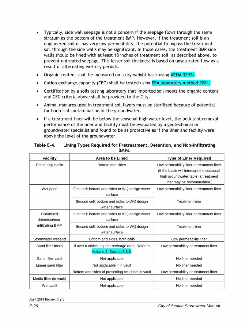
Table E-4. Lining Types Required for Pretreatment, Detention, and Non-infiltrating BMPs.
Facility Area to be Lined Type of Liner Required
Presettling basin Bottom and sides Low permeability liner or treatment liner
(If the basin will intercept the seasonal
high groundwater table, a treatment
liner may be recommended.)
Wet pond First cell: bottom and sides to WQ design water
surface
Low permeability liner or treatment liner
Second cell: bottom and sides to WQ design
water surface
Treatment liner
Combined
detention/non-
infiltrating BMP
First cell: bottom and sides to WQ design water
surface
Low permeability liner or treatment liner
Second cell: bottom and sides to WQ design
water surface
Treatment liner
Stormwater wetland Bottom and sides, both cells Low permeability liner
Sand filter basin If over a critical aquifer recharge area. Refer to
Volume 3, Section 5.8.5.
Low permeability or treatment liner
Sand filter vault Not applicable No liner needed
Linear sand filter Not applicable if in vault
Bottom and sides of presettling cell if not in vault
No liner needed
Low permeability or treatment liner
Media filter (in vault) Not applicable No liner needed
Wet vault Not applicable No liner needed

April 2014 Review Draft
City of Seattle Stormwater Manual E-27
Design Criteria for Low Permeability Liners
This section presents the design criteria for each of the following four low permeability liner
options: compacted till liners, clay liners, geomembrane liners, and concrete liners. For low
permeability liners, the following criteria apply:
Where the seasonal high groundwater elevation is likely to contact a low permeability
liner, liner buoyancy may be a concern. In these instances, use of a low permeability
liner shall be evaluated and recommended by a geotechnical engineer.
Where grass must be planted over a low permeability liner per the facility design, a
minimum of 6 inches of good topsoil or compost-amended native soil (2 inches
compost tilled into 6 inches of native till soil) must be placed over the liner in the
area to be planted. Twelve inches of cover is preferred.
Compacted Till Liners
Liner thickness shall be 18 inches after compaction.
Soil shall be compacted to 95 percent minimum dry density, modified proctor method
(ASTM D-1557).
A different depth and density sufficient to retard the infiltration rate to 2.4 x 10⁻⁵
inches per minute (1 x 10⁻⁶ cm/s) may also be used instead of Criteria 1 and 2 above.
Soil shall be placed in 6-inch lifts.
Soils must meet the gradation outlined in Table E-5.
Table E-5. Compacted Till Liners.
Sieve Size Percent Passing
6-inch 100
4-inch 90
#4 70 – 100
#200 20
Clay Liners
Liner thickness shall be 12 inches.
Clay shall be compacted to 95 percent minimum dry density, modified proctor method
(ASTM D-1557).
A different depth and density sufficient to retard the infiltration rate to 2.4 x 10⁻⁵
inches per minute (1 x 10⁻⁶ cm/s) may also be used instead of the above criteria, if
approved by the Director.
Plasticity index shall not be less than 15 percent (ASTM D-423, D-424).
Liquid limit of clay shall not be less than 30 percent (ASTM D-2216).
Clay particles passing shall not be less than 30 percent (ASTM D-422).

April 2014 Review Draft
E-28 City of Seattle Stormwater Manual
The slope of clay liners must be restricted to 3H: 1V for all areas requiring soil cover;
otherwise, the soil layer must be stabilized by another method so that soil slippage
into the facility does not occur. Any alternative soil stabilization method must take
maintenance access into consideration.
Where clay liners form the sides of ponds, the interior side slope shall not be steeper
than 3H: 1V, irrespective of fencing. This restriction is to ensure that anyone falling
into the pond may safely climb out.
Geomembrane Liners
Geomembrane liners shall be ultraviolet (UV) light resistant and have a minimum
thickness of 30 mils. A thickness of 40 mils shall be used in areas of maintenance
access or where heavy machinery must be operated over the membrane.
The geomembrane fabric shall be protected from puncture, tearing, and abrasion by
installing geotextile fabric on the top and bottom of the geomembrane determined to
have a high survivability per the WSDOT Standard Specifications as Amended,
specifically Section 9-33 Construction Geotextile. Equivalent methods for protecting
the geomembrane liner may be permitted, subject to approval by Director.
Equivalency will be judged on the basis of ability to protect the geomembrane from
puncture, tearing, and abrasion.
Geomembranes shall be bedded according to the manufacturer's recommendations.
Liners must be covered with 12 inches of top dressing forming the bottom and sides of
the water quality treatment facility, except for linear sand filters. Top dressing shall
consist of 6 inches of crushed rock covered with 6 inches of native soil. The rock layer
is to mark the location of the liner for future maintenance operations. As an
alternative to crushed rock, 12 inches of native soil may be used if orange plastic
“safety fencing” or another highly-visible, continuous marker is embedded 6 inches
above the membrane.
If possible, liners should be of a contrasting color so that maintenance workers are
aware of any areas where a liner may have become exposed when maintaining the
facility.
Geomembrane liners shall not be used on slopes steeper than 5H:1V to prevent the top
dressing material from slipping. Textured liners may be used on slopes up to 3H:1V
upon recommendation by a geotechnical engineer that the top dressing will be stable
for all site conditions, including maintenance.
Concrete Liners
Concrete liners may also be used for sedimentation chambers and for sedimentation
and filtration basins less than 1,000 square feet in area. Concrete shall be 5-inch-thick
Class 3000 or better and shall be reinforced by steel wire mesh. The steel wire mesh
shall be 6 gage wire or larger and 6 inch by 6 inch mesh or smaller. An "Ordinary
Surface Finish" is required. When the underlying soil is clay or has an unconfined
compressive strength of 0.25 ton per square foot or less, the concrete shall have a
minimum 6 inch compacted aggregate base consisting of coarse sand and river stone,

April 2014 Review Draft
City of Seattle Stormwater Manual E-29
crushed stone or equivalent with diameter of 0.75 to 1 inch. Where visible, the
concrete shall be inspected annually and all cracks shall be sealed.
Portland cement liners are allowed irrespective of facility size, and shotcrete may be
used on slopes. However, specifications must be developed by a professional engineer
who certifies the liner against cracking or losing water retention ability under
expected conditions of operation, including facility maintenance operations. Weight of
maintenance equipment can be up to 80,000 pounds when fully loaded.
Asphalt concrete may not be used for liners due to its permeability to many organic
pollutants.
If grass is to be grown over a concrete liner, slopes must be no steeper than 5H:1V to
prevent the top dressing material from slipping. Textured liners may be used on slopes
up to 3H:1V upon recommendation by a geotechnical engineer that the top dressing
will be stable for all site conditions, including maintenance.

April 2014 Review Draft
City of Seattle Stormwater Manual E-31
E-8. GEOTEXTILES
The following recommended applications are provided courtesy of Tony Allen (Geotechnical
Engineer-WSDOT) with references provided to the relevant tables in the City of Seattle
Standard Specifications:
For sand filter drain strip between the sand and the drain rock or gravel layers specify
Geotextile Properties for Underground Drainage, moderate survivability, Class A, from
Tables 1 and 2 in the City of Seattle Standard Specifications 9-37.
For sand filter matting located immediately above the impermeable liner and below
the drains, the function of the geotextile is to protect the impermeable liner by acting
as a cushion. The specification provided in Table 4 in the City of Seattle Standard
Specifications 9-37 should be used to specify survivability properties for the liner
protection application. Table 2 in the City of Seattle Standard Specifications 9-37,
Class C should be used for filtration properties. Only nonwoven geotextiles are
appropriate for the liner protection application.
For an infiltration drain specify Geotextile for Underground Drainage, low
survivability, Class C, from Tables 1 and 2 in the City of Seattle Standard
Specifications 9-37.
For a sand bed cover a geotextile fabric is placed exposed on top of the sand layer to
trap debris brought in by the stormwater and to protect the sand, facilitating easy
cleaning of the surface of the sand layer. However, a geotextile is not the best
product for this application. A polyethylene or polypropylene geonet would be better.
The geonet material should have high UV resistance (90 percent or more strength
retained after 500 hours in the weatherometer, ASTM D4355), and high permittivity
(ASTM D4491, 0.8 sec -1 or more) and percent open area (CWO-22125, 10 percent or
more). Tensile strength should be on the order of 200 pounds grab (ASTM D4632) or
more.

April 2014 Review Draft
City of Seattle Stormwater Manual E-33
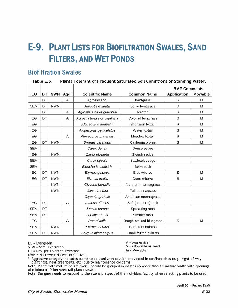
E-9. PLANT LISTS FOR BIOFILTRATION SWALES, SAND
FILTERS, AND WET PONDS
Biofiltration Swales
Table E.5. Plants Tolerant of Frequent Saturated Soil Conditions or Standing Water.
EG DT NWN Agg1 Scientific Name Common Name
BMP Comments
Application Mowable
DT A Agrostis spp. Bentgrass S M
SEMI DT NWN Agrostis exarata Spike bentgrass S M
DT A Agrostis alba or gigantea Redtop S M
EG DT A Agrostis tenuis or capillaris Colonial bentgrass S M
EG Alopecurus aequalis Shortawn foxtail S M
EG Alopecurus geniculatus Water foxtail S M
EG A Alopecurus pratensis Meadow foxtail S M
EG DT NWN Bromus carinatus California brome S M
SEMI Carex densa Dense sedge
EG NWN Carex obnupta Slough sedge
SEMI Carex stipata Sawbeak sedge
SEMI Eleocharis palustris Spike rush
EG DT NWN Elymus glaucus Blue wildrye S M
EG DT NWN Elymus mollis Dune wildrye S M
NWN Glyceria borealis Northern mannagrass
NWN Glyceria elata Tall mannagrass
Glyceria grandis American mannagrass
EG DT A Juncus effusus Soft (common) rush
SEMI DT Juncus patens Spreading rush
SEMI DT Juncus tenuis Slender rush
EG A Poa trivialis Rough-stalked bluegrass S M
SEMI NWN Scirpus acutus Hardstem bulrush
SEMI DT NWN Scirpus microcarpus Small-fruited bulrush
EG = Evergreen SEMI = Semi-Evergreen DT = Drought Tolerant/Resistant NWN = Northwest Natives or Cultivars
A = Aggressive S = Allowable as seed M = Mowable
1 Aggressive category indicates plants to be used with caution or avoided in confined sites (e.g., right-of-way plantings), near greenbelts, etc. due to maintenance concerns
Note: Plants with mature height over 3' should be grouped in masses no wider than 12' mature width with openings of minimum 10' between tall plant masses. Note: Designer needs to respond to the size and aspect of the individual facility when selecting plants to be used.
April 2014 Review Draft
E-34 City of Seattle Stormwater Manual
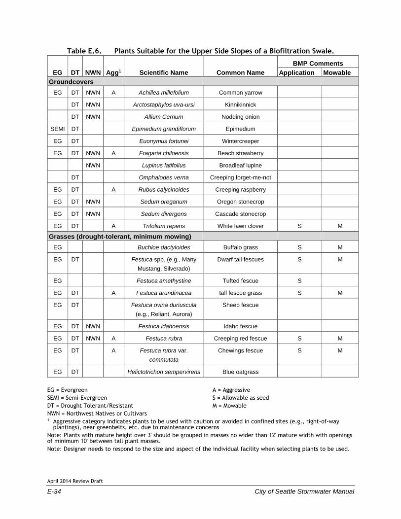
Table E.6. Plants Suitable for the Upper Side Slopes of a Biofiltration Swale.
EG DT NWN Agg1 Scientific Name Common Name
BMP Comments
Application Mowable
Groundcovers
EG DT NWN A Achillea millefolium Common yarrow
DT NWN Arctostaphylos uva-ursi Kinnikinnick
DT NWN Allium Cernum Nodding onion
SEMI DT Epimedium grandiflorum Epimedium
EG DT Euonymus fortunei Wintercreeper
EG DT NWN A Fragaria chiloensis Beach strawberry
NWN Lupinus latifolius Broadleaf lupine
DT Omphalodes verna Creeping forget-me-not
EG DT A Rubus calycinoides Creeping raspberry
EG DT NWN Sedum oreganum Oregon stonecrop
EG DT NWN Sedum divergens Cascade stonecrop
EG DT A Trifolium repens White lawn clover S M
Grasses (drought-tolerant, minimum mowing)
EG Buchloe dactyloides Buffalo grass S M
EG DT Festuca spp. (e.g., Many
Mustang, Silverado)
Dwarf tall fescues S M
EG Festuca amethystine Tufted fescue S
EG DT A Festuca arundinacea tall fescue grass S M
EG DT Festuca ovina duriuscula
(e.g., Reliant, Aurora)
Sheep fescue
EG DT NWN Festuca idahoensis Idaho fescue
EG DT NWN A Festuca rubra Creeping red fescue S M
EG DT A Festuca rubra var.
commutata
Chewings fescue S M
EG DT Helictotrichon sempervirens Blue oatgrass
EG = Evergreen
SEMI = Semi-Evergreen
DT = Drought Tolerant/Resistant
NWN = Northwest Natives or Cultivars
A = Aggressive
S = Allowable as seed
M = Mowable
1 Aggressive category indicates plants to be used with caution or avoided in confined sites (e.g., right-of-way plantings), near greenbelts, etc. due to maintenance concerns
Note: Plants with mature height over 3' should be grouped in masses no wider than 12' mature width with openings of minimum 10' between tall plant masses.
Note: Designer needs to respond to the size and aspect of the individual facility when selecting plants to be used.

April 2014 Review Draft
City of Seattle Stormwater Manual E-35
Table E.7. Recommended Plants for Wet Biofiltration Swales.
EG DT NWN Agg1 Scientific Name Common Name
BMP Comments
Application Mowable
SEMI DT NWN Agrostis exarata Spike bentgrass S M
EG DT A Agrostis tenuis or capillaris Colonial bentgrass S M
Alopecurus aequalis Shortawn foxtail S M
Alopecurus geniculatus Water foxtail S M
Eleocharis spp. Spike rush
SEMI Carex densa Dense sedge
EG NWN Carex obnupta Slough sedge
SEMI NWN Carex stipata Sawbeak sedge
Carex spp. Sedge
EG DT A Festuca arundinacea var. Tall fescue grass S M
EG DT NWN A Festuca rubra Creeping red fescue S M
Glyceria occidentalis Western mannagrass
EG DT A Juncus effusus Soft (common) rush
SEMI DT Juncus patens Spreading rush
SEMI DT NWN Juncus tenuis Slender rush
EG A Lolium perenne - Var. dwarf Dwarf ryegrass S
SEMI NWN Oenanthe sarmentosa Water parsley
SEMI NWN Scirpus acutus Hardstem bulrush
SEMI DT NWN Scirpus microcarpus Small-fruited bulrush
EG = Evergreen
SEMI = Semi-Evergreen
DT = Drought Tolerant/Resistant
NWN = Northwest Natives or Cultivars
A = Aggressive
S = Allowable as seed
M = Mowable
1 Aggressive category indicates plants to be used with caution or avoided in confined sites (e.g., right-of-way plantings), near greenbelts, etc. due to maintenance concerns
Note: Plants with mature height over 3' should be grouped in masses no wider than 12' mature width with openings of minimum 10' between tall plant masses.
Note: Designer needs to respond to the size and aspect of the individual facility when selecting plants to be used.

April 2014 Review Draft
E-36 City of Seattle Stormwater Manual
Sand Filters
Table E.8. Recommended Plants for Sand Filters.
EG DT NWN Agg1 Scientific Name Common Name
BMP Comments
Application Mowable
Basin Sides
DT NWN Achillea millefolium Yarrow S
EG DT Agrostis alba Redtop S M
EG DT NWN Agrostis exerata Spike bentgrass S M
EG DT Agrostis palustris Creeping bentgrass S M
DT Alopecurus pratensis Meadow foxtail S M
EG DT NWN Bromus carinatus California Brome S M
DT NWN Calamagrostis nutkaensis Pacific reed grass
EG DT NWN Elymus glaucus Blue wildrye S M
EG DT NWN Elymus mollis Dune wildrye S M
EG DT NWN A Juncus effusus Soft rush S
DT NWN Lupinus albicaulus Sickle keeled lupine S
EG DT NWN Luzula multiflora Field woodrush S
DT A Poa palustris Fowl bluegrass S M
EG A Poa pratensis Kentucky bluegrass S M
Pond Bottom (Sand Surface)
EG DT Agrostis tenuis Colonial bentgrass
(Highland strain good)
S M
DT Buchloe dactyloides Buffalo grass S M
DT NWN Camassia leichlinii or quamash camas
EG DT NWN Carex mertensii Merten's sedge S
EG DT NWN Festuca elatior (arundinacea) Tall fescue S M
EG DT NWN Festuca elatior "Many
Mustang", "Silverado"
Dwarf tall fescues S M
EG DT NWN Fescue roemeri (idahoensis) Roemer's or Idaho fescue S
EG DT NWN Festuca rubra Red fescue S M
SEMI DT NWN Iris missouriensis Rocky Mountain iris
EG DT NWN Juncus tenuis Slender rush S
EG DT Lolium perenne Perennial ryegrass S M
EG DT NWN Luzula parviflora Small flowered woodrush S
EG DT Trifolium repens White lawn clover S M
EG DT Zoysia tenuifolia Korean grass S M
EG = Evergreen SEMI = Semi-Evergreen DT = Drought Tolerant/Resistant NWN = Northwest Natives or Cultivars
A = Aggressive S = Allowable as seed M = Mowable
1 Aggressive category indicates plants to be used with caution or avoided in confined sites (e.g., right-of-way plantings), near greenbelts, etc. due to maintenance concerns
Note: Plants with mature height over 3' should be grouped in masses no wider than 8' mature size with openings of min. 10' between tall plant masses. Note: Designer needs to respond to the size and aspect of the individual facility when selecting plants to be used.

April 2014 Review Draft
City of Seattle Stormwater Manual E-37
Wet Ponds
Table E.9. Plants for Wet Pond Peripheries.
EG DT NWN Agg1 Scientific Name Common Name
BMP Comments
Application2 Mature Height
Trees to Provide Shading3
DT NWN Acer circinatum Vine maple W 25'
Betula nigra River birch W 40'
EG NWN Myrica californica Pacific wax myrtle 18'
Nyssa Sylvatica Tupelo W 40'
NWN Oemleria cerasiformis Indian plum 10'
NWN Prunus emarginata Wild cherry 40'
Taxus brevifolia Pacific yew 40'
EG DT NWN Thuja plicata Western red cedar W 40'
Small Trees / High Shrubs with Fibrous Roots for Berms
NWN Acer circinatum Vine maple W 25'
NWN Amelanchier alnifolia Serviceberry 25'
EG DT Arbutus unedo Strawberry tree 25'
NWN Comus Stolonifera Red twig dogwood W 20'
NWN Corylus comuta var. cornuta Filbert 20'
NWN Physocarpus capitatus Pacific ninebark 12'
NWN A Rubus spectabillis Salmonberry W 8'
NWN Sambucus racemosa Red elderberry 10'
Vaccinium opulus Highbush cranberry 10'
Vaccinium spp. Blueberry 4'-12'
Low Shrubs and Grasses with Fibrous Roots for Berms
EG NWN Arctostaphylos uva-ursi Kinnickinnick 0.5'
Cistus spp. Rock rose 2'-4'
SEMI NWN Deschampsia cespitosa Tufted hairgrass 3'
EG DT Festuca arundinacea tall fescue grass 3'
EG DT Festuca ovina duriuscula
(e.g., Reliant, Aurora)
Sheep fescue 1'
NWN Festuca rubra red fescue W 0.5'
EG NWN Gaultheria shallon Salal 4'
Helictotrichon sempervirens blue oatgrass 3'
EG NWN Ledum groenlandicum Labrador tea W 5'
Polystichum munitum sword fern W 4'
NWN A Symphoricarpus albus Snowberry 5'
(A) e.g., Miscanthis, Pennisetum Ornamental grasses varies
EG = Evergreen
SEMI = Semi-Evergreen
DT = Drought Tolerant/Resistant
NWN = Northwest Natives or Cultivars
A = Aggressive
W = Wet Tolerant

April 2014 Review Draft
E-38 City of Seattle Stormwater Manual
1 Aggressive category indicates plants to be used with caution or avoided in confined sites (e.g., right-of-way plantings), near greenbelts, etc. due to maintenance concerns
2 Tolerant of occasional saturated soils or minimal inundation (< 6" depth) for short periods (< 72 hours). 3 If BMP has a liner, designer should review plants accordingly; trees generally are not appropriate to liner
conditions.
Note: Plants with mature height over 3' should be grouped in masses no wider than 8' mature size with openings of min. 10' between tall plant masses.
Note: Designer needs to respond to the size and aspect of the individual facility when selecting plants to be used.
Note: Many factors contribute to waterfowl use of ponds and adjacent areas. Designers should investigate site-specific conditions and best practice methods to discourage waterfowl use as necessary.