appendix d technical standard operating procedures (sops
TRANSCRIPT
Appendix D Technical Standard Operating Procedures (SOPs) for the SSFL Phase 3 Sampling SSFL SOP 1 - Procedures for Locating and Clearing Phase 3 Samples SSFL SOP 2 - Surface Soil Sampling SSFL SOP 3 - Subsurface Soil Sampling with Hand Auger SSFL SOP 4 - Direct Push Technology (DPT) Sampling SSFL SOP 5 - Backhoe Trenching/Test Pits for Sample Collection SSFL SOP 6 - Field Measurement of Total Organic Vapors SSFL SOP 7 - Field Measurement of Residual Radiation SSFL SOP 8 - Field Data Collection Documents, Content and Control SSFL SOP 9 - Lithologic Logging SSFL SOP 10 - Sample Custody SSFL SOP 11 - Packaging and Shipping Environmental Samples SSFL SOP 12 - Field Equipment Decontamination SSFL SOP 13 - Guide to Handling Investigation Derived Waste SSFL SOP 14 - Geophysical Survey SSFL SOP 15 - Photographic Documentation of Field Activities SSFL SOP 16 - Control of Measurement and Test Equipment SSFL SOP 17 - Laboratory Homogenization For Phase 3 Soil Samples SSFL SOP 18 - Clean Sampling Method for Methyl Mercury and Organotin
Analyses
SSFL Use Only
Technical Standard Operating Procedures Page 1 of 7 © 2012CDM Federal Programs Corporation All Rights Reserved
Procedures for Locating and Clearing Phase 3 Samples SSFL SOP 1 Revision: 0 Date: April 2012
Prepared: J. Sobol Technical Review: C. Werden
QA Review: J. Oxford Approved and Issued:
4/6/2012
Signature/Date
1.0 Objective The objective of this technical standard operating procedure (SOP) is to describe the sample location and utility clearance protocols for the Phase 3 - Chemical Data Gap Investigation at the Santa Susana Field Laboratory (SSFL) site. Because this phase of investigation is targeted at minimizing data gaps in the understanding of the nature and extent of chemical contaminants in surface (0 to 0.5 foot) and subsurface (0.5 to 20 feet) soil, the precise location of each soil sample location is very important. 2.0 Background 2.1 Definitions Data Gap Analysis–An analysis that identifies specific soil sample locations and depths for which insufficient data exists. The analysis is to minimize the data gap and ensure that collected data are representative of the study area. MWH, Inc. (MWH; under a separate agreement with Department of Energy [DOE]) is performing this effort. Staked Location–Proposed sample location marked on the ground surface either with fluorescent paint (on concrete or asphalt), metal pins with fluorescent nylon whiskers, or wooden stakes marked with the sample location identifier installed at the exact sample locations identified through the MWH data gap analysis. GPS– Global Positioning System that measures east-west and north-south coordinates of sample locations. GeoExplorer 6000 Series Handheld Unit–GPS field unit used to survey proposed and actual sample locations. Utility Locate–A survey of all proposed sample locations for underground utilities, including, but not limited to, water lines, sewer lines, storm sewer lines, gas lines, electric lines, and telecommunication lines. Performed by subcontractor. Fisher TW-6-M-Scope Pipe and Cable Locator (or equivalent)-A field unit used to identify detectable electrically conductive conduits or piping which may have no surface expression. Radiodetection RD4000 Utility Locator (or equivalent)-A field unit used to locate the surface trace of a variety of buried utilities. Metrotech 50/60 Power Line Locator (or equivalent)–A field unit used to detect conduits that carry 60-cycle current. 3M Dynatel 2250 Cable Locator (or equivalent)-A field unit used to detect the surface trace of telephone and other narrow gauge wiring. 2.2 Associated Procedures SSFL SOP 2, Surface Soil Sampling SSFL SOP 3, Subsurface Soil Sampling with Hand Auger SSFL SOP 4, Direct Push Technology (DPT) Sampling SSFL SOP 5, Backhoe Trenching/Test Pits for Sample Collection SSFL SOP 6, Field Measurement of Total Organic Vapor SSFL SOP 7, Field Measurement of Residual Radiation SSFL SOP 8, Field Data Collection Documents, Content, and Control SSFL SOP 14, Geophysical Survey
SSFL Use Only
Technical Standard Operating Procedures Page 2 of 7 © 2012CDM Federal Programs Corporation All Rights Reserved
Procedures for Locating and Clearing Phase 3 Samples SSFL SOP 1 Revision: 0 Date: April 2012
SSFL SOP 16, Control of Measurement and Test Equipment 2.3 Discussion Geographic Information System (GIS) sample location files will be received from MWH for field verification and those locations staked using global GPS location identification procedures. Office and field verification of GPS coordinates is necessary for determining the precise location of each sample point and to ensure the adequacy of signal strength of the GPS equipment. Inaccessible locations due to underground utilities, site geology, or that do not target the identified site will be assigned alternate locations by CDM Smith. Using GPS, site coordinate data will be collected at the alternative location and the updated surveyed location data will be electronically provided to MWH for updating the Area IV GIS. All proposed sample locations will be marked in the field using fluorescent paint, metal pins, or wooden stakes. Following MWH review of the relocated marked sample locations, CDM Smith will complete any additional required utility/geophysics clearances of the sample location and initiate sampling. In addition, protection of cultural and natural resources is an integral portion of locating sample points. Cultural, biological, and Native American monitors will be engaged throughout the process. Quality control measures will be implemented during GPS field collection and during post processing of confirmed or relocated sample locations. 3.0 General Responsibilities Field Team Leader - The field team leader (FTL) is responsible for ensuring that field personnel collect soil and sediment samples in accordance with this SOP and other relevant procedures. Site Health and Safety Technician– The person who will use field screening instruments to monitor all field activities for VOCs and radiological contaminants and pre-shipment sample coolers. This person is a trained radiological technician who works under the guidance of Science Application International Corporation’s (SAIC’s) Certified Health Physicist (CHP). Site Geologist – The person responsible for attending sample location efforts and collecting and logging the soil sample. Utility Locator Subcontractor – The subcontractor is responsible for identifying all buried utilities in the vicinity of soil borings, trenches, and test pits. 4.0 Required Equipment 4.1 General Site-specific plans (e.g., Field Sampling Plan
[FSP] Addendum, health and safety) 3M Dynatel 2250 Cable Locator (or equivalent) to detect the surface
trace of telephone and other narrow gauge wiring Mapping of proposed sample locations Fisher TW-6-M-Scope Pipe and Cable Locator (or equivalent) Mapping of known utilities Radiodetection RD4000 Utility Locator (or equivalent) Fluorescent paint and metal pins or wooden
stakes Metrotech 50/60 Power Line Locator (or equivalent) to detect
conduits that carry 60-cycle current Field logbook GeoExplorer 6000 Series Handheld GPS Unit 2-way radios Sample rationale table (Table 1 of FSP Addendum) Monitoring and screening instruments per the
health and safety plan
5.0 Procedures 5.1 Field Staking 1. MWH provides specific data gap sample location information (i.e., GIS coordinates, map, and table) to CDM Smith for
field use. The sample information includes: Sample rationale (sampling objective) Sample location Depth interval Analytical suite
SSFL Use Only
Technical Standard Operating Procedures Page 3 of 7 © 2012CDM Federal Programs Corporation All Rights Reserved
Procedures for Locating and Clearing Phase 3 Samples SSFL SOP 1 Revision: 0 Date: April 2012
2. The figures showing proposed sample locations are provided to the cultural, biological, and Native American monitors in advance of field verification so they can review their records for any cultural or biological resources in the vicinity of the sampling areas.
3. A minimum of four working days advanced notice of field work is required for the cultural and biological resource reviews.CDM Smith will meet with the monitors to discuss concerns. Sample locations in areas of resource concern are reported back to CDM Smith and revised sample locations are discussed with DOE, the California Department of Toxic Substances Control (DTSC) and MWH.
4. Once all locations have been reviewed, the GIS sample location coordinates are loaded into the GPS (See Section 5.2) for field staking.
5. CDM Smith’s Sample Location Team mobilizes to each proposed sampling location. This Team consists of: CDM Smith’s FTL/Geologist CDM Smith Site Health and Safety Technician Utility Location Technician Science Applications International Corporation’s (SAIC’s) Archaeological/Cultural Resource Compliance
representative SAIC’s Natural Resource Compliance representative Native American monitor
6. The FTL locates each sample station using the GPS. The FTL verifies that the location addresses the sampling
rationale stated for the location in the FSP Addendum (Table 1). If it does, the location is marked with fluorescent paint and metal pins with fluorescent nylon whiskers or wooden stakes at the precise GIS/GPS coordinates.
7. If the location is identified by the cultural, natural resource, or Native American monitor as a location of concern, they will demarcate restricted areas as necessary and determine the degree of support necessary for each sample location during the intrusive investigation (soil boring or excavation). Each proposed sample location is also preliminarily screened for radiation.
8. Once staked, the FTL will escort the subcontract utility locator (See Section 5.3) to clear all proposed sample locations for underground utilities. Samples locations affected by underground utilities will be noted, and an alternative location staked to avoid the utility. All adjusted sample locations will be reviewed with DOE, DTSC, and MWH; and the cultural and natural resource, and Native American monitors.
9. Proposed locations may be adjusted based on the following considerations:
sample locations that are impacted by overhead/underground utilities sample locations that are impacted by steep or non-accessible terrain or exposed bedrock sample locations that are impacted by archaeological/cultural resources sample locations that are impacted by biological resources sample locations that did not meet the intent of the MWH sample rationale
10. Using the final GPS coordinates, CDM Smith will provide the updated the sample location data to MWH for updating the
Area IV GIS. A revised sample location map will be incorporated into the FSP Addendum and provided to DOE and DTSC.
11. DOE, DTSC, and MWH will have the opportunity to review all sample locations in the field and approve/accept the
locations. Locations noted to be impacted or not meeting the intent of the sample collection rationale will be reviewed and direction will be provided to the FTL. Coordinates for adjusted samples locations will be immediately collected using the GPS unit and marked in the field as described above. Markers/paint of samples locations that will not be used will be destroyed at that time.
12. At each location, additional field-check of the sample location (coordinates) will be performed using the GPS unit at the time of sample collection.
SSFL Use Only
Technical Standard Operating Procedures Page 4 of 7 © 2012CDM Federal Programs Corporation All Rights Reserved
Procedures for Locating and Clearing Phase 3 Samples SSFL SOP 1 Revision: 0 Date: April 2012
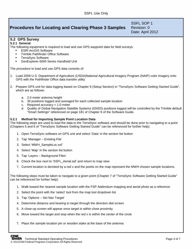
5.2 GPS Survey 5.2.1 General The following equipment is required to load and use GPS waypoint data for field surveys. ESRI ArcGIS Software Trimble Pathfinder Office Software TerraSync Software GeoExplorer 6000 Series Handheld Unit
The procedure to load and use GPS data consists of: 1. Load 2009 U.S. Department of Agriculture (USDA)National Agricultural Imagery Program (NAIP) color imagery onto
GPS with the Pathfinder Office data transfer utility
2. Prepare GPS unit for data logging based on Chapter 9 (Setup Section) in “TerraSync Software Getting Started Guide”, which are as follows:
a. 2.0 meter antenna height b. 30 positions logged and averaged for each collected sample location c. Required accuracy < 1.0 meter d. Quality of Global Navigation Satellite Systems (GNSS) positions logged will be controlled by the Trimble default
“Smart Settings” referenced on page 181 of Chapter 9 of the Software Guide.
5.2.1 Method for Importing Sample Point Location Data The following steps are used to load the data to the TerraSync software and should be done prior to navigating to a point (Chapters 5 and 6 of “TerraSync Software Getting Started Guide” can be referenced for further help):
1. Open TerraSync software on GPS unit and select ‘Data’ in the section list button
2. Tap ‘Manager – Existing File’
3. Select ‘MWH_SampleLoc.ssf’
4. Select ‘Map’ in the section list button
5. Tap ‘Layers – Background Files’
6. Check the box next to ‘SSFL_Aerial.sid’ and return to map view
7. Current location is denoted by a red x and the points on the map represent the MWH chosen sample locations.
The following steps must be taken to navigate to a given point (Chapter 7 of “TerraSync Software Getting Started Guide” can be referenced for further help):
1. Walk toward the nearest sample location with the FSP Addendum mapping and aerial photo as a reference
2. Select the point with the ‘select’ tool from the map tool dropdown list
3. Tap ‘Options – Set Nav Target’
4. Determine distance and bearing to target through the direction dial screen
5. A close-up screen will appear once target is within close proximity
6. Move toward the target and stop when the red x is within the center of the circle
7. Place the sample location pin or wooden stake at the base of the antenna
SSFL Use Only
Technical Standard Operating Procedures Page 5 of 7 © 2012CDM Federal Programs Corporation All Rights Reserved
Procedures for Locating and Clearing Phase 3 Samples SSFL SOP 1 Revision: 0 Date: April 2012
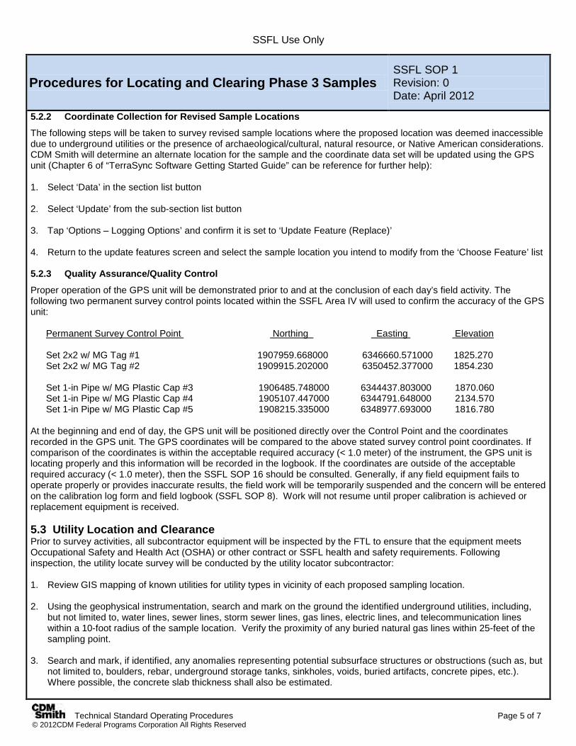
5.2.2 Coordinate Collection for Revised Sample Locations
The following steps will be taken to survey revised sample locations where the proposed location was deemed inaccessible due to underground utilities or the presence of archaeological/cultural, natural resource, or Native American considerations. CDM Smith will determine an alternate location for the sample and the coordinate data set will be updated using the GPS unit (Chapter 6 of “TerraSync Software Getting Started Guide” can be reference for further help): 1. Select ‘Data’ in the section list button
2. Select ‘Update’ from the sub-section list button
3. Tap ‘Options – Logging Options’ and confirm it is set to ‘Update Feature (Replace)’
4. Return to the update features screen and select the sample location you intend to modify from the ‘Choose Feature’ list 5.2.3 Quality Assurance/Quality Control
Proper operation of the GPS unit will be demonstrated prior to and at the conclusion of each day’s field activity. The following two permanent survey control points located within the SSFL Area IV will used to confirm the accuracy of the GPS unit:
Permanent Survey Control Point Northing Easting
1. Review GIS mapping of known utilities for utility types in vicinity of each proposed sampling location.
Elevation Set 2x2 w/ MG Tag #1 1907959.668000 6346660.571000 1825.270 Set 2x2 w/ MG Tag #2 1909915.202000 6350452.377000 1854.230 Set 1-in Pipe w/ MG Plastic Cap #3 1906485.748000 6344437.803000 1870.060 Set 1-in Pipe w/ MG Plastic Cap #4 1905107.447000 6344791.648000 2134.570 Set 1-in Pipe w/ MG Plastic Cap #5 1908215.335000 6348977.693000 1816.780
At the beginning and end of day, the GPS unit will be positioned directly over the Control Point and the coordinates recorded in the GPS unit. The GPS coordinates will be compared to the above stated survey control point coordinates. If comparison of the coordinates is within the acceptable required accuracy (< 1.0 meter) of the instrument, the GPS unit is locating properly and this information will be recorded in the logbook. If the coordinates are outside of the acceptable required accuracy (< 1.0 meter), then the SSFL SOP 16 should be consulted. Generally, if any field equipment fails to operate properly or provides inaccurate results, the field work will be temporarily suspended and the concern will be entered on the calibration log form and field logbook (SSFL SOP 8). Work will not resume until proper calibration is achieved or replacement equipment is received. 5.3 Utility Location and Clearance Prior to survey activities, all subcontractor equipment will be inspected by the FTL to ensure that the equipment meets Occupational Safety and Health Act (OSHA) or other contract or SSFL health and safety requirements. Following inspection, the utility locate survey will be conducted by the utility locator subcontractor:
2. Using the geophysical instrumentation, search and mark on the ground the identified underground utilities, including,
but not limited to, water lines, sewer lines, storm sewer lines, gas lines, electric lines, and telecommunication lines within a 10-foot radius of the sample location. Verify the proximity of any buried natural gas lines within 25-feet of the sampling point.
3. Search and mark, if identified, any anomalies representing potential subsurface structures or obstructions (such as, but not limited to, boulders, rebar, underground storage tanks, sinkholes, voids, buried artifacts, concrete pipes, etc.). Where possible, the concrete slab thickness shall also be estimated.

SSFL Use Only
Technical Standard Operating Procedures Page 6 of 7 © 2012CDM Federal Programs Corporation All Rights Reserved
Procedures for Locating and Clearing Phase 3 Samples SSFL SOP 1 Revision: 0 Date: April 2012
4. Additional soil boring/test pit utility clearing of all locations within a 10-foot radius of an identified utility or anomaly. Any identified utilities and anomalies shall be marked on the ground surface, on a hand-drawn sketch, and on a scaled site map. Note: All test pit excavations require coordination and onsite oversight of the cultural, natural resource, and Native American monitors.
5. Provide field notes, hand-drawn sketches and scaled maps of each survey location to the FTL at the conclusion of each day. CDM Smith will make available to the subcontractor scaled base maps for the site.
All known surface and subsurface utilities located within the Area IV GIS will be used, in part, to determine the level of effort for clearing individual boring/test pit locations in (a) non-developed areas and (b) developed or previously developed areas or areas with known utilities. These areas and effort are discussed below. 5.3.1 Non-Developed Areas The utility subcontractor will perform a reconnaissance survey of all areas that have no historic record of development and are absent of known utilities (as illustrated by the Area IV GIS). The subcontractor will physically inspect all or a portion of the area as necessary to provide assurance that the area does not contain utilities. The subcontractor will determine the identification method and effort necessary and communicate this information to the FTL prior to commencing of sampling activities in those areas. Following approval from the FTL or geologist, the utility subcontractor will clear soil boring/test pit locations. The utility subcontractor will mark utilities/features on the ground within the designated areas using a color code established by the American Public Works Association (and provided by the subcontractor). 5.3.2 Developed Areas and Areas with Know Utilities In developed areas, the exteriors of the buildings, curbsides, streets, and/or land where building demolishing and dismantling activities have taken place, the utility subcontractor will visually inspect proposed sample/test pit locations for evidence of utilities. Exposed tracer wire or portions of metallic conduits and pipe will be used to conduct a signal with the instrument appropriate for a given type of utility. All utilities/features identified using conductive signals will be marked on the ground within the designated areas using a color code established by the American Public Works Association (and provided by the subcontractor). The utility subcontractor will physically inspect all or a portion of the proposed sampling/test pit area as necessary to provide assurance that the area does not contain utilities and to identify any surface features (depressions, pits, trenches, etc.) or anomaly representing potential subsurface structures or obstructions (such as, but not limited to, boulders, rebar, underground storage tanks, voids, buried artifacts, concrete pipes, etc.). For areas where soil borings are located within 10 feet, and test pits are within 50 feet, of an identified utility or identified subsurface features or anomaly, additional clearing of the soil boring/test pit location will be required. The utility subcontractor will provide additional clearing activities at these locations as described below. Equipment/instruments that do not use an induced current via pipe/conduit/wire will be swept over the ground surface within the designated clearance area. The signals will be traced at the surface and the underground utility or features will be delineated. At a minimum, two 20-foot transects that are perpendicular to each other will be run within the diameter of each survey area. The transects will be centered on the boring/test pit location. Any surface features and anomaly representing potential subsurface structures or obstructions shall be identified and marked as appropriate. Where possible, the concrete slab thickness shall also be estimated. 5.4 Onsite Equipment and Vehicle Requirements All equipment will be cleaned prior to entering and leaving SSFL. Vehicles are restricted to asphalt roads and parking lots and will be free of leaks. If vehicles or any equipment is leaking it will be taken out of service immediately and the fluids will be contained. Under CDM Smith’s direction, the subcontractor will immediately clean up any petroleum or hydrocarbon fluid spills. Boeing, DOE, and DTSC will be immediately notified of any spills at the site.
SSFL Use Only
Technical Standard Operating Procedures Page 7 of 7 © 2012CDM Federal Programs Corporation All Rights Reserved
Procedures for Locating and Clearing Phase 3 Samples SSFL SOP 1 Revision: 0 Date: April 2012
6.0 Restrictions/Limitations 6.1 GPS Survey Instruments External factors with the potential to degrade the quality of GPS data and the locating capabilities of the GPS are inherent within the GPS environment. A low signal to noise ratio (SNR), a high Position Dilution of Precision (PDOP), a multipath (GPS signal hits a physical barrier, thus reducing reflectivity), and a changing satellite constellation can all impact the quality of the GPS data. Because the equipment and logging settings are pre-determined for this project, inaccurate data due to the aforementioned external factors and potential human input errors should be minimized. The quality control procedures outlined in Section 5.2.3 will be followed to reduce GPS data quality issues/concerns. 7.0 References National Geodetic Survey. 2012. “What We Do”. http://www.ngs.noaa.gov/INFO/WhatWeDo.shtml Trimble. 2012. “GPS Pathfinder Office Software”. http://www.trimble.com/mappingGIS/PathfinderOffice.aspx?dtID=applications& ______. 2011. ”TerraSync Software Getting Started Guide: TerraSync Software”. V5.10, Revision A. http://trl.trimble.com/dscgi/ds.py/Get/File-529465/TerraSync_GSG_v510_RevA_ENG.pdf. February. U.S. Department of Agriculture (USDA) Farm Service Agency. 2012. “Imagery Programs”. http://www.fsa.usda.gov/FSA/apfoapp?area=home&subject=prog&topic=nai. .
SSFL Use Only
Technical Standard Operating Procedures Page 1 of 5 © 2012CDM Federal Programs Corporation All Rights Reserved
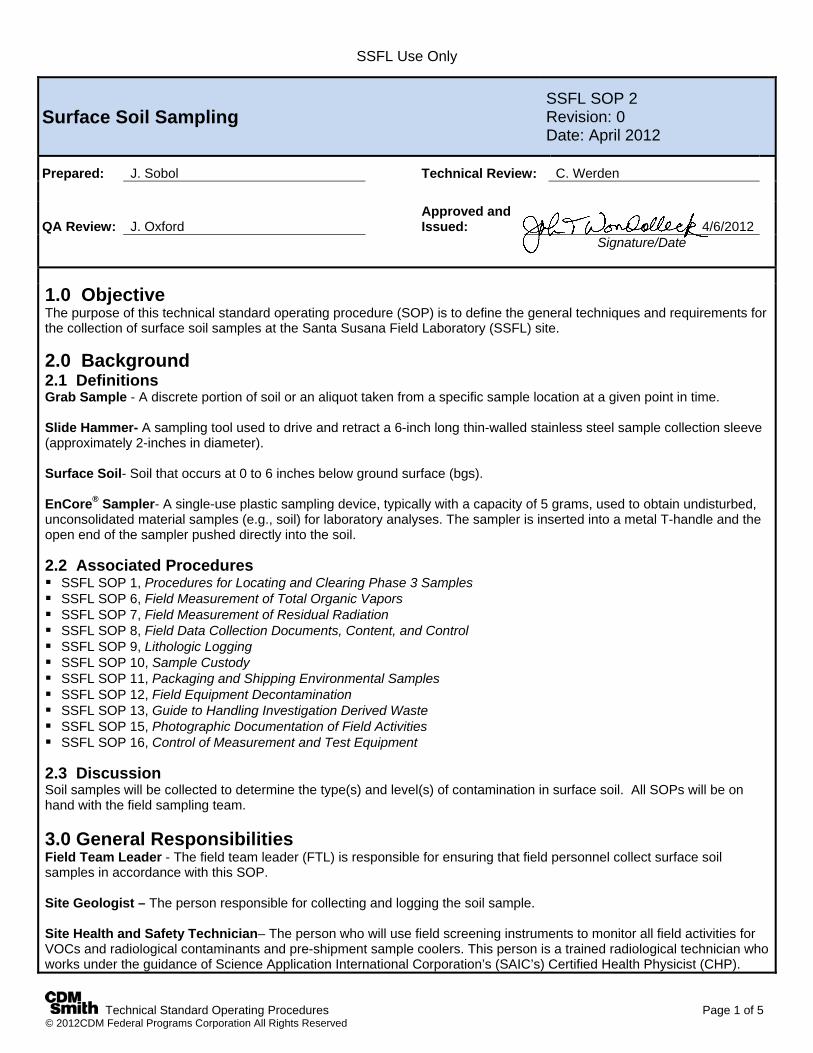
Surface Soil Sampling SSFL SOP 2 Revision: 0 Date: April 2012
Prepared: J. Sobol Technical Review: C. Werden
QA Review: J. Oxford Approved and Issued:
4/6/2012
Signature/Date
1.0 Objective The purpose of this technical standard operating procedure (SOP) is to define the general techniques and requirements for the collection of surface soil samples at the Santa Susana Field Laboratory (SSFL) site.
2.0 Background 2.1 Definitions Grab Sample - A discrete portion of soil or an aliquot taken from a specific sample location at a given point in time. Slide Hammer- A sampling tool used to drive and retract a 6-inch long thin-walled stainless steel sample collection sleeve (approximately 2-inches in diameter). Surface Soil- Soil that occurs at 0 to 6 inches below ground surface (bgs). EnCore® Sampler- A single-use plastic sampling device, typically with a capacity of 5 grams, used to obtain undisturbed, unconsolidated material samples (e.g., soil) for laboratory analyses. The sampler is inserted into a metal T-handle and the open end of the sampler pushed directly into the soil. 2.2 Associated Procedures SSFL SOP 1, Procedures for Locating and Clearing Phase 3 Samples SSFL SOP 6, Field Measurement of Total Organic Vapors SSFL SOP 7, Field Measurement of Residual Radiation SSFL SOP 8, Field Data Collection Documents, Content, and Control SSFL SOP 9, Lithologic Logging SSFL SOP 10, Sample Custody SSFL SOP 11, Packaging and Shipping Environmental Samples SSFL SOP 12, Field Equipment Decontamination SSFL SOP 13, Guide to Handling Investigation Derived Waste SSFL SOP 15, Photographic Documentation of Field Activities SSFL SOP 16, Control of Measurement and Test Equipment 2.3 Discussion Soil samples will be collected to determine the type(s) and level(s) of contamination in surface soil. All SOPs will be on hand with the field sampling team. 3.0 General Responsibilities Field Team Leader - The field team leader (FTL) is responsible for ensuring that field personnel collect surface soil samples in accordance with this SOP. Site Geologist – The person responsible for collecting and logging the soil sample. Site Health and Safety Technician– The person who will use field screening instruments to monitor all field activities for VOCs and radiological contaminants and pre-shipment sample coolers. This person is a trained radiological technician who works under the guidance of Science Application International Corporation’s (SAIC’s) Certified Health Physicist (CHP).
SSFL Use Only
Technical Standard Operating Procedures Page 2 of 5 © 2012CDM Federal Programs Corporation All Rights Reserved
Surface Soil Sampling SSFL SOP 2 Revision: 0 Date: April 2012
4.0 Required Equipment Site-specific plans (including Field Sampling Plan [FSP]
Addendum and health and safety plan) Monitoring/screening instruments required by health and
safety plan Insulated cooler Nitrile or other appropriate protective gloves Plastic zip-top bags Field logbook Personal protective clothing and equipment Indelible blue or black ink pen and/or marker Slide hammer with stainless steel sleeves Decontamination supplies EnCore samplers and T-handle Paper towels or Kim wipes Clear, waterproof tape Custody seals Securely-sealed bags of ice Chain of custody forms Plastic sheeting Sample labels Appropriate sample containers Teflon squares and sleeve end caps Global Positioning System (GPS) unit 2-way radios Trash Bags Disposable plastic spoons and knives 5.0 Procedures 5.1 Preparation The following steps must be followed when preparing for sample collection: 1. Review site-specific health and safety plan and project plans (FSP Addendum) before initiating sampling activity. 2. Don the appropriate personal protective clothing as specified in the site-specific health and safety plan. 3. Locate sampling location(s) in accordance with FSP Addendum and document pertinent information in the field
logbook (SSFL SOP 8). Confirm GPS coordinates of each location (SSFL SOP 1). 4. Use clean (decontaminated) sampling tools to obtain sample material from each specified sample location. 5. Carefully remove stones, vegetation, debris, etc. from the ground surface in the sampling location area. Clear the sample
location using a new and/or appropriately decontaminated tool as described to expose a fresh sampling surface. 6. The Site Health and Safety Technician will perform contaminant screening using hand-held instruments at each sample
location before sampling and for each sample collected (SSFL SOPs 6 and 7). The most recent spoils materials will be segregated to minimize cross-contamination. The breathing zone and excavated materials will be monitored continuously. If levels are detected above health and safety plan action levels (HASP page 8), work will be temporarily discontinued. If radiation levels, exceed two times (2X) background levels (HASP page 8), the Department of Energy (DOE), The Boeing Company (Boeing), and the California Department of Toxic Substances Control (DTSC) will be contacted. Site work will not resume at that location until further guidance is provided by DOE or Boeing. Contact information is in the health and safety plan.
The following steps must be taken to prepare the slide hammer for sampling. 1. Obtain the slide hammer, sample tube with the shoe, and stainless steel liners. 2. Remove the sample tube shoe and insert a clean liner. Screw the shoe back onto the sample tube. 3. Screw the assembled sample tube onto the slide hammer. 4. After sampling, remove the sampling liner from the sample tube for sample collection.
5. Decontaminate the sample tube and shoe.
SSFL Use Only
Technical Standard Operating Procedures Page 3 of 5 © 2012CDM Federal Programs Corporation All Rights Reserved
Surface Soil Sampling SSFL SOP 2 Revision: 0 Date: April 2012
5.2 Sample Collection The following general steps must be followed when collecting surface soil samples. 1. Wear new, clean gloves during handling of all sample containers and sampling devices. Change out gloves at each
sampling location, or each time a new sample is to be collected, to avoid cross-contamination. 2. Document the sampling process by recording applicable information in the designated field logbook. Document any and
all deviations from the SOPs and the sampling plan in the field logbook and include rationale for changes. See SSFL SOP 8 for guidance on entering information into field log books.
3. Because sampling for volatile organic compounds (VOCs) is not anticipated for most surface soil locations, the procedure
for non-VOC sample collection is described first (Section 5.2.1). When sampling of VOCs is required (i.e., identified in Table 1 of FSP Addendum, observed stained soil, petroleum odor, or elevated photoionization detector [PID] reading) at any location, collect the required sample aliquot for volatile analyses (Section 5.2.2) first, as well as any other samples that may be degraded by aeration, followed by the collection of samples for other analyses.
5.2.1 Method for Collecting Samples for Nonvolatile Organic or Inorganic Compound Analyses The requirements for collecting samples of surface soil for nonvolatile organic or inorganic analyses are as follows: 1. Use a clean slide hammer and decontaminated stainless steel sleeves to drive a sample from 0 to 6-inches bgs.
Several sleeves may be required from this interval to collect the amount of surface soil to satisfy the analytical protocol (refer to Table 1 in the FSP Addendum). Quickly screen the open end of the sleeve and the sample borehole for VOCs and radioactivity (SSFL SOPs 6 and 7).
2. Collect subsamples for chromium (Cr3+) and/or hexavalent chrome (Cr6+) and/or pH from the center of the stainless steel sleeve into a glass jar using a disposable plastic spoon or knife. Ensure that the soil that was in contact with the sleeve is not collected in the jar.
3. Prior to capping the sleeve for the remaining non-volatile parameters, place a Teflon® cover sheets over each end of the
sample. Secure the respective cap on each sample container immediately after collection. Label the sample sleeve with “top” and “bottom” designations.
4. Wipe the sample containers with a clean paper towel or Kimwipe to remove any residual soil from the sample container
surface. 5. Fill out the sample label with the appropriate sample information (e.g., sample identification, date/time of sample
collection, requested analyses) per FSP Addendum Table 1 and attach to sample sleeve. 6. Place sample containers in individual zip-top plastic bags and seal the bags. Place baggies onto ice in an insulated cooler
to maintain at 4°C (2°C). 7. Decontaminate all non-disposable sampling equipment in accordance with SSFL SOP 12. 5.2.2 Method for Collecting Soil Samples for Volatile Organic Compound Analysis The following text contains the recommended SW-846 Test Method 5035 procedure for sampling and field preservation of soil samples for VOC analysis, which includes the EnCore™ Sampler Method for low-level VOC analyses. 1. When collecting grab sampling for VOC analysis, it is necessary to minimize sample disturbance and consequently
minimize analyte loss. 2. Wear new, clean gloves during handling of all sample containers and sampling devices. Change out gloves at each
sampling location, or each time a new sample is to be collected, to avoid cross-contamination.
SSFL Use Only
Technical Standard Operating Procedures Page 4 of 5 © 2012CDM Federal Programs Corporation All Rights Reserved
Surface Soil Sampling SSFL SOP 2 Revision: 0 Date: April 2012
3. VOC samples shall be collected first as grab samples. After clearing sample site, use a clean slide hammer and decontaminated stainless steel sleeves to drive a sample from 0 to 6-inches bgs. EnCore samplers will be used to collect subsamples for the required analytical protocol (e.g., VOCs, 1,4-dioxane, and total petroleum hydrocarbons-gasoline range organics [TPH-GRO]). The VOC sample will be collected from the bottom of the 6-inch stainless steel sleeve. Several slide hammer samples (stainless steel liners) may be required at the location to obtain the required sample volume for all VOC samples.
4. Once the sleeve is retrieved, quickly screen the open end of the sleeve and the sample borehole for VOCs and
radioactivity (SSFL SOPs 6 and 7). 5. Remove the EnCore sampler and cap from package and attach T-handle to sampler body. Ensure that the sampler is
locked into the T-Handle before sampling. 6. Push the sampler into the freshly-exposed soil in the bottom of the sampler sleeve until the O-ring is visible within the hole
on the side of the T-handle. If the O-ring is not visible within this window, then the sampler is not full. 7. Extract the sampler and wipe the sampler sides with a clean paper towel or Kimwipe so that the sampler cap can be
tightly attached. 8. While still locked into the T-handle, push the sampler cap on the head of the sampler with a twisting motion to secure it to
the sampler body. 9. Remove the sampler from the T-handle and rotate the sampler stem counterclockwise until the stem locks in place to
retain the sample within the sampler body. 10. Repeat procedure for each of the remaining samplers. 11. When collecting soil samples using the EnCore Sampler Method, collection of soil for moisture content analysis is
required. Results of the moisture analysis are used to adjust “wet” concentration results to “dry” concentrations to meet analytical method requirements. The moisture sample will be collected in a separate 4 oz. glass jar. Following EnCore sample collection (typically five samplers but verify that the FSP Addendum may require more), fill one 4 oz. jar with soil from bottom of a stainless steel sleeve for moisture analysis using a disposable plastic spoon or knife.
12. After VOC and moisture sampling, discard the remaining soil within the stainless steel sleeves back into the borehole. 13. Complete the sample labels by filling in the appropriate information (e.g., sample identification, date and time of sample
collection, and requested analyses [per FSP Addendum]) and secure the label to the container. 14. Store samples at 4°C (2°C) until samples are delivered to the designated analytical laboratory. Determine sample
holding times with the appropriate analytical laboratory. Samples must be shipped and delivered to the analytical laboratory for extraction within 48 hours.
15. Pack all samples per SSFL SOP 11 and/or laboratory requirements. Include properly completed documentation and affix
signed and dated custody seals to the cooler lid. See SSFL SOP 10 for guidance on sample custody procedures. 16. Decontaminate all non-disposable sampling equipment in accordance with SSFL SOP 12.
Note: A water trip blank will be included with sample coolers containing VOC samples. 5.2.3 Sample Packing and Shipment 1. Store samples at 4°C (2°C) until samples are delivered to the designated analytical laboratory. 2. Pack all samples per SSFL SOP 11 and/or laboratory requirements. Include properly completed documentation and affix
signed and dated custody seals to the cooler lid. See SSFL SOP 10 for guidance on sample custody procedures.

SSFL Use Only
Technical Standard Operating Procedures Page 5 of 5 © 2012CDM Federal Programs Corporation All Rights Reserved
Surface Soil Sampling SSFL SOP 2 Revision: 0 Date: April 2012
6.0 Restrictions/Limitations Before conducting the soil sampling at each location, underground utilities and structures must be demarcated on the ground surface. In addition, archeological and cultural resources as well as Native American cultural concerns must be cleared. A subcontractor will be used to locate and mark the utility lines. The selected sampling location shall be a safe distance from the demarcated utility. In some cases, records regarding utility locations may not exist. Also, as presented in Section 5.2.2 of this SOP, when grab sampling for VOC analysis or other compound(s) that may be compromised by aeration, it is necessary to minimize sample disturbance and consequently minimize analyte loss. The representativeness of a VOC grab sample is difficult to determine because the collected sample represents a single point, is not homogenized, and has been disturbed.
7.0 References U.S. Department of Energy. 1996. Hazardous Waste Remedial Actions Program. Quality Control Requirements for Field Methods, DOE/HWP-69/R2. September. __________. Hazardous Waste Remedial Actions Program. Standard Operating Procedures for Site Characterizations, DOE/HWP-100/R1. September 1996 or current revision. U. S. Environmental Protection Agency. Test Methods for Evaluating Solid Waste, Physical/Chemical Methods (SW-846), Third Edition, November 1986, (as amended by Updates I, II, IIA, IIB, III, and IIIA, June 1997). Method 5035 (Note: § 6.2.1.8 of this method says samples stored in EnCore™ samplers shall be analyzed within 48 hours or transferred to soil sample vials in the laboratory within 48 hours): December 1996, Revision O, Closed-System Purge-and-Trap and Extraction for Volatile Organics in Soil and Waste Samples.
SSFL Use Only
Technical Standard Operating Procedures Page 1 of 6 © 2012CDM Federal Programs Corporation All Rights Reserved
Subsurface Soil Sampling With Hand Auger SSFL SOP 3 Revision: 0 Date: April 2012
Prepared: J. Sobol Technical Review: C. Werden
QA Review: J. Oxford Approved and Issued:
4/6/2012
Signature/Date
1.0 Objective The objective of this technical standard operating procedure (SOP) is to define the techniques and requirements for collecting shallow subsurface soil samples for environmental characterization purposes from the unconsolidated subsurface zone. The sampling techniques discussed in this SOP involve use of hand augers at the Santa Susana Field Laboratory (SSFL) site. 2.0 Background 2.1 Definitions Slide Hammer- A drive tool is used to drive and retract a 6-inch long (and approximately 2 inches in diameter), thin-walled stainless steel sleeve. Hand Auger - A stainless steel cylinder (bucket) approximately 3 to 4 inches (in) in diameter and 1 foot (ft) in length, open at both ends with the bottom edge designed to advance perpendicular to the ground surface with a twisting motion into unconsolidated subsurface material to obtain a soil sample. The auger has a T-shaped handle (fixed or ratchet used for manual operation) attached to the top of the bucket by extendable stainless steel rods. EnCore® Sampler- A disposable plastic sampling device, typically with a capacity of 5 grams, used to obtain undisturbed, unconsolidated material samples (e.g., soil) for laboratory analyses. The sampler is inserted into a metal T-handle and the open end of the sampler pushed directly into the soil. Subsurface Soil - The unconsolidated, or non-lithified, material that exists deeper than approximately 6 inches below the ground surface (bgs). Unconsolidated Zone - A layer of non-lithified earth material (soil) that has no mineral cement or matrix binding its grains. 2.2 Associated Procedures SSFL SOP 1, Procedures for Locating and Clearing Phase 3 Samples SSFL SOP 6, Field Measurement of Total Organic Vapors SSFL SOP 7, Field Measurement of Residual Radiation SSFL SOP 8, Field Data Collection Documents, Content, and Control SFSL SOP 9, Lithologic Logging SSFL SOP 10, Sample Custody SSFL SOP 11, Packaging and Shipping Environmental Samples SSFL SOP 12, Field Equipment Decontamination SSFL SOP 13, Guide to Handling Investigation Derived Waste SSFL SOP 15, Photographic Documentation of Field Activities SSFL SOP 16, Control of Measurement and Test Equipment
2.3 Discussion Subsurface soil samples, or those taken from depths below 6 inches, are collected using a hand auger to depths up to 10 ft bgs or bedrock refusal. Subsurface samples in locations inaccessible to a DPT rig will be collected by drilling using hand augers to the sample depth, and then sample collection from the auger hole using a slide hammer and stainless steel sleeves. The maximum depth of hand auger samples is typically 10 feet bgs. All sample locations and sample materials will be screened by the Site Health and Safety Technician using hand-help instruments. In addition, all SOPs will be on hand
SSFL Use Only
Technical Standard Operating Procedures Page 2 of 6 © 2012CDM Federal Programs Corporation All Rights Reserved
Subsurface Soil Sampling With Hand Auger SSFL SOP 3 Revision: 0 Date: April 2012
with the field sampling team. 3.0 General Responsibilities Field Team Leader - The field team leader is responsible for ensuring that field personnel collect subsurface soil samples in accordance with this SOP. Site Geologist – The person responsible for collecting and logging the soil sample. Site Health and Safety Technician– The person who will use field screening instruments to monitor all field activities for VOCs and radiological contaminants and pre-shipment sample coolers. This person is a trained radiological technician who works under the guidance of Science Application International Corporation’s (SAIC’s) Certified Health Physicist (CHP). 4.0 Required Equipment 4.1 General Site-specific plans (e.g., Field Sampling Plan [FSP]
Addendum, health and safety) Monitoring/screening equipment per health and
safety plan Field logbook Personal protective clothing and equipment Appropriate sample containers Plastic sheeting EnCore samplers and T-handle Plastic zip-top bags Insulated cooler(s) Chain-of-custody forms Bags of ice Custody seals Nitrile or appropriate gloves Sample labels Clear, waterproof tape Decontamination supplies Indelible black ink pens and markers Kimwipes or paper towels Slide hammer with stainless steel sleeves Teflon squares and sleeve end caps Global Positioning System (GPS) unit Trash bags 2-way radios Disposable plastic spoons or knives 4.2 Manual (Hand) Auger Sampling T-handle Extension rods Hand auger: extensions, bucket-, or tube-type auger as
required by the site-specific plans Wrench(es), pliers
5.0 Procedures 5.1 Preparation 1. Review site-specific health and safety plan and FSP Addendum before initiating sampling activity. 2. Don the appropriate personal protective clothing as indicated in the site-specific health and safety plan. 3. Locate sampling location(s) in accordance with FSP Addendum and document pertinent information in the appropriate
field logbook (SSFL SOP 8). Confirm GPS coordinates of each location (SSFL SOP 1). 4. Use clean, (decontaminated) sampling tools to obtain sample material from each specified sample location. 5. Carefully remove stones, vegetation, debris, etc. from the ground surface in the sampling location area. Clear the sample
location using a new and/or appropriately decontaminated tool as described to expose a fresh sampling surface. 6. The Site Health and Safety Technician will perform contaminant screening using hand-held instruments at each sample
location before sampling and for each sample collected (SSFL SOPs 6 and 7). The most recent spoils materials will be segregated to minimize cross-contamination. The breathing zone and excavated materials will be monitored continuously. If levels are detected above health and safety plan action levels (HASP page 8), work will be temporarily discontinued. If radiation levels exceed two-times (2X) background levels (HASP page 8), the Department of Energy

SSFL Use Only
Technical Standard Operating Procedures Page 3 of 6 © 2012CDM Federal Programs Corporation All Rights Reserved
Subsurface Soil Sampling With Hand Auger SSFL SOP 3 Revision: 0 Date: April 2012
(DOE),The Boeing Company (Boeing), and the California Department of Toxic Substances Control (DTSC) will be contacted. Site work will not resume at that location until further guidance is provided by DOE or Boeing. Contact information is in the health and safety plan.
The following steps must be taken to prepare the slide hammer for sampling. 1. Obtain the slide hammer, sample tube with the shoe and stainless steel liners. 2. Remove the sample tube shoe and insert a clean liner. Screw the shoe back onto the sample tube. 3. Screw the assembled sample tube onto the slide hammer. 4. After sampling remove the sampling liner from the sample tube for sample collection. 5. Decontaminate the sample tube and shoe. 5.2 Sample Collection The following general steps must be followed when collecting all subsurface soil samples. Soil samples will be preserved by placing the samples on ice. 1. Wear clean gloves during handling of sample containers and sampling devices. Change out gloves at each sampling
location, or each time a new sample is to be collected, to avoid cross-contamination. 2. VOC samples or samples that may be degraded by aeration will be collected first and with the least disturbance possible to
minimize sample disturbance and consequently minimize analyte loss. 3. While advancing the hand auger, the subsurface lithology shall be described according to SSFL SOP 9. 4. Specific sampling devices are identified in the FSP Addendum and will be recorded in the field logbook. Document any
and all deviations from the SOPs and the sampling plan in the field logbook and include rationale for changes. See SSFL SOP 8 for guidance on entering information into field log books.
5. Care must be taken to prevent cross-contamination and misidentification of samples as described in subsequent
subsections of this SOP. 5.2.1 Manual (Hand) Auger Sampling Using a Slide Hammer The following steps must be followed when collecting environmental soil samples using a hand-auger and slide hammer: 1. Auger to the depth required for sampling, per the FSP Addendum. Place cuttings on plastic sheeting. If possible, lay out
the cuttings in stratigraphic order. 2. During auger advancement and sample collection, record observations made of the geologic features of the soil or
sediments per SSFL SOP 9. 3. Stop advancing the auger when the top of the specified sampling depth has been reached. Remove the auger from the
hole and set aside for future decontamination (see line item 11 below). 4. Obtain the subsurface soil sample by driving the sample sleeve through the specified sample interval with the slide
hammer. Remove the stainless steel liner from the slide hammer and quickly screen the sleeve for VOCs and radiation (SSFL SOPs 6 and 7).
5. Immediately subsample for VOCs (if required) by FSP Addendum Table 1, observe stained soil, petroleum odor, or
elevated PID reading) by pushing the EnCore sampler into the soil in the bottom end of the sampling sleeve. See Section 5.2.2 and 5.2.3.
SSFL Use Only
Technical Standard Operating Procedures Page 4 of 6 © 2012CDM Federal Programs Corporation All Rights Reserved
Subsurface Soil Sampling With Hand Auger SSFL SOP 3 Revision: 0 Date: April 2012
6. Proceed with additional sample depth collection as required by the FSP Addendum. 7. When sampling is complete, place cuttings back into the borehole and top off with bentonite pellets, and hydrate as
necessary to bring former borehole to ground surface. Place plastic sheeting and gloves in garbage bag and transfer decontamination water to storage container as specified SSFL SOP 13.
8. Decontaminate all equipment between each sample according to SSFL SOP 12. 9. Complete the field logbook entry and other forms, being sure to record all relevant information before leaving the
sample location. 10. Properly package all samples for shipment and complete all necessary sample shipment documentation. Remand
custody of samples to the appropriate personnel. See SSFL SOPs 10 and 11. 5.2.2 Method for Collecting Soil Samples for Volatile Organic Compound Analysis The following text contains the recommended SW-846 Test Method 5035 procedure for sampling and field preservation of soil samples for volatile organic compound (VOC) analysis, which includes the EnCore® Sampler Method for low-level VOC analyses. 1. When collecting grab sampling for VOC analysis, it is necessary to minimize sample disturbance and consequently
minimize analyte loss. 2. Wear new, clean gloves during handling of sample containers and sampling devices. Change out gloves at each sampling
location, or each time a new sample is to be collected, to avoid cross-contamination. 3. VOC samples shall be collected first as grab samples. EnCore samplers will be used to collect subsamples for the required
analytical protocol (e.g., VOCs, 1,4-dioxane, and total petroleum hydrocarbon-gasoline range organics [TPH-GRO]) from sample sleeves collected at depth. The VOC sample will be collected from the bottom of the 6-inch stainless steel sleeve. Several slide hammer samples (stainless steel liners) may be required to obtain the required sample volume for all VOC analyses.
4. Once the sleeve is retrieved, quickly screen the open end of the sleeve and the sample borehole for VOCs and
radioactivity (SSFL SOPs 6 and 7). 5. Remove EnCore sampler and cap from package and attach T-handle to sampler body. Ensure that the sampler is locked
into the T-handle before sampling. 6. Push the sampler into the freshly-exposed soil in the bottom of the sampler sleeve until the O-ring is visible within the hole
on the side of the T-handle. If the O-ring is not visible within this window, then the sampler is not full. 7. Extract the sampler and wipe the sampler sides with a clean paper towel or Kimwipe so that the sampler cap can be tightly
attached. 8. While still locked into the T-handle, push the sampler cap on the head of the sampler with a twisting motion to secure it to
the sampler body. 9. Remove the sampler from the T-handle and rotate the sampler stem counterclockwise until the stem locks in place to
retain the sample within the sampler body. 10. Repeat procedure for each of the remaining samplers. 11. When collecting soil samples using the EnCore Sampler Method, collection of soil for moisture content analysis is required.
Results of the moisture analysis are used to adjust “wet” concentration results to “dry” concentrations to meet analytical
SSFL Use Only
Technical Standard Operating Procedures Page 5 of 6 © 2012CDM Federal Programs Corporation All Rights Reserved
Subsurface Soil Sampling With Hand Auger SSFL SOP 3 Revision: 0 Date: April 2012
method requirements. The moisture sample will be collected in a separate 4 oz. glass jar. After collecting the required number of EnCore samples (typically five), fill one 4 oz. jar with soil from bottom of stainless steel sleeve for moisture analysis using a disposable plastic spoon or knife.
12. After VOC and moisture sampling, discard the remaining soil within the stainless steel sleeves back into the borehole. 13. Complete the sample labels by filling in the appropriate information (e.g., sample identification, date and time of sample
collection, and requested analyses [per FSP Addendum]) and securing the label to the container. 14. Store samples at 4°C (2°C) until samples are delivered to the designated analytical laboratory. Determine sample holding
times with the appropriate analytical laboratory. Samples must be shipped and delivered to the analytical laboratory for extraction within 48 hours.
15. Pack all samples per SSFL SOP 11 and/or laboratory requirements. Include properly completed documentation and affix
signed and dated custody seals to the cooler lid. See SSFL SOP10 for guidance on sample custody procedures. 16. Decontaminate all non-disposable sampling equipment in accordance with SSFL SOP 12.
Note: A water trip blank will be included with sample coolers containing VOC samples. 5.2.3 Method for Collecting Samples for Nonvolatile Organic or Inorganic Compound Analyses The requirements for collecting samples of subsurface soil for nonvolatile organic or inorganic analyses are as follows: 1. Use a clean slide hammer and decontaminated stainless steel sleeves to drive a sample through a 6-inch interval at the
prescribed depth. Several sleeves may be required from this interval to collect the necessary amount of subsurface soil to satisfy the analytical protocol (refer to sampling rationale Table 1 in the FSP Addendum). Quickly screen the open end of the sleeve and the sample borehole for VOCs and radioactivity (SSFL SOPs 6 and 7).
2. Collect sub samples for chromium (Cr3+) and/or hexavalent chrome (Cr6+) and or pH from the center of the stainless steel sleeve into a glass jar using a disposable plastic spoon or knife. Ensure that the soil that was in contact with the sleeve is not collected in the jar.
3. Prior to capping the sleeve for the remaining non-volatile parameters, place a Teflon® cover sheets over each end of the
sample. Secure the respective cap on each sample container immediately after collection.
4. Label the sample sleeve with “top” and “bottom” designations. 5. Wipe the sample containers with a clean paper towel or Kimwipe to remove any residual soil from the sample container
surface. 6. Fill out the sample label with the appropriate sample information (e.g., sample identification, date/time of sample collection,
requested analyses) per FSP Addendum Table 1 and attach to sample sleeve. 7. Place sample containers in individual zip-top plastic bags and seal the bags. Place baggies onto ice in an insulated cooler
to maintain at 4°C (2°C). 8. Decontaminate all non-disposable sampling equipment in accordance with SSFL SOP 12. 5.2.4 Sample Packing and Shipment 1. Store samples at 4°C (2°C) until samples are delivered to the designated analytical laboratory. 2. Pack all samples per SSFL SOP 11 and/or laboratory requirements. Include properly completed documentation and affix
signed and dated custody seals to the cooler lid. See SSFL SOP 10 for guidance on sample custody procedures.
SSFL Use Only
Technical Standard Operating Procedures Page 6 of 6 © 2012CDM Federal Programs Corporation All Rights Reserved
Subsurface Soil Sampling With Hand Auger SSFL SOP 3 Revision: 0 Date: April 2012
6.0 Restrictions/Limitations Before conducting the soil sampling at each location, underground utilities and structures must be demarcated on the ground surface. In addition, archeological and cultural resources as well as Native American cultural concerns must be cleared. A subcontractor will be used to locate and mark the utility lines. The selected sampling location shall be a safe distance from the demarcated utility. In some cases, records regarding utility locations may not exist. Also, when grab sampling for VOC analysis or for analysis of any other compound(s) that may be degraded by aeration, it is necessary to minimize sample disturbance and analyte loss. The representativeness of a VOC grab sample is difficult to determine because the collected sample represents a single point, is not homogenized, and has been disturbed. 7.0 References American Society for Testing and Materials. 1999. Standard Test Method for Penetration Test and Split Barrel Sampling of Soils. Standard Method D1586-99. __________.2000. Standard Test Method for Thin-Walled Tube Sampling of Soils for Geotechnical Purposes. Standard Method D1587-00. U. S. Department of Energy.1996. Hazardous Waste Remedial Actions Program. Quality Control Requirements for Field Methods, DOE/HWP-69/R2. September. __________. Hazardous Waste Remedial Actions Program. Standard Operating Procedures for Site Characterizations, DOE/HWP-100/R1. September 1996 or current revision. U.S. Environmental Protection Agency. Test Methods for Evaluating Solid Waste, Physical/Chemical Methods (SW-846), Third Edition, November 1986, (as amended by Updates I, II, IIA, IIB, III, and IIIA, June 1997). Method 5035 (Note: § 6.2.1.8 of this method says samples stored in EnCore™ samplers shall be analyzed within 48 hours or transferred to soil sample vials in the laboratory within 48 hours): December 1996, Revision O, Closed-System Purge-and-Trap and Extraction for Volatile Organics in Soil and Waste Samples.
SSFL Use Only
Technical Standard Operating Procedures Page 1 of 7 © 2012CDM Federal Programs Corporation All Rights Reserved
Direct Push Technology (DPT) Sampling SSFL SOP 4 Revision: 0 Date: April 2012
Prepared: J. Sobol Technical Review: C. Werden
QA Review: J. Oxford Approved and Issued:
4/6/2012
Signature/Date
1.0 Objective The objective of this technical standard operating procedure (SOP) is to define the requirements for collecting subsurface soil using direct push technology (DPT) sampling techniques at the Santa Susana Field Laboratory (SSFL) site. 2.0 Background 2.1 Definitions DPT rig- A hydraulically-operated hammer device installed on the back of a van, pickup truck, or skid used to advance a hollow-stem rod and sampler into the subsurface soil (up to bedrock refusal) to collect subsurface soil samples. Probe-Driven Sampler - A sampling device, similar to a split-spoon sampler, used to collect soil samples with a DPT rig. The sampler is 5-foot steel core barrel with an acetate liner to contain the sample. Extension Rod - Stainless steel rod used to remove stop-pin and drive-point assembly. Drive Point - Solid steel retractable point used to advance sample collection device to the required sample depth. Probe Rod - Hollow, flush-threaded, steel rod similar to a drill rod. Stop-Pin - Steel plug that threads into the top of the drive cap to hold the drive point in place during advancement of the probe rods. Drive Cap - Threaded, hardened-steel top cap that attaches to the top of the probe rod; used when advancing the probe rods with the hydraulic hammer. Pull Cap - Threaded, hardened-steel top cap that attaches to the top of the probe rod; used when retracting the probe rods. 2.2 Associated Procedures SSFL SOP 1, Procedures for Locating and Clearing Phase 3 Samples SSFL SOP 6, Field Measurement of Total Organic Vapors SSFL SOP 7, Field Measurement of Residual Radiation SSFL SOP 8, Field Data Collection Documents, Content, and Control SSFL SOP 9, Lithologic Logging SSFL SOP 10, Sample Custody SSFL SOP 11, Packaging and Shipping Environmental Samples SSFL SOP 12, Field Equipment Decontamination SSFL SOP 13, Guide to Handling Investigation Derived Waste SSFL SOP 15, Photographic Documentation of Field Activities SSFL SOP 16, Control of Measurement and Test Equipment 2.3 Discussion The DPT rig consists of a hydraulically-operated hammer device mounted on the back of a van, a pickup truck or a skid. The DPT system hydraulically advances small-diameter, hollow rods and sampler to the desired sampling depth. The specific type of DPT sampling equipment for soil sample collection is then deployed. This work will be performed by a subcontractor with
SSFL Use Only
Technical Standard Operating Procedures Page 2 of 7 © 2012CDM Federal Programs Corporation All Rights Reserved
Direct Push Technology (DPT) Sampling SSFL SOP 4 Revision: 0 Date: April 2012
CDM Smith oversight. The use of DPT technology is a cost-effective alternative to using conventional drilling techniques for collecting subsurface soil samples given the site-specific geologic and hydrogeologic conditions and sample requirements. Advantages of using the DPT system include: Areas usually considered inaccessible by drill rigs because of terrain and vegetation, overhead wires, size constraints, etc.,
may be accessed with a van- or pickup truck-mounted DPT rig. Investigation-derived wastes such as soil cuttings and purge water are minimized due to its small diameter rods and its
displacement of soil horizontally, not vertically. In addition, all SOPs will be on hand with the field sampling team. 3.0 General Responsibilities DPT Subcontractor–Subcontractor retained to perform all DPT drilling activities. Field Team Leader (FTL)-The FTL is responsible for ensuring that sampling efforts are conducted in accordance with this procedure and the Field Sampling Plan (FSP) Addendum. Site Health and Safety Technician–The person who will use field screening instruments to monitor all field activities for VOCs and radiological contaminants and pre-shipment sample coolers. This person is a trained radiological technician who works under the guidance of Science Application International Corporation’s (SAIC’s) Certified Health Physicist (CHP). Site Geologist–The person responsible for overseeing sample collecting, recording sampling information and for logging the soil sample. 4.0 Required Equipment General Site-specific plans (e.g., Field Sampling Plan [FSP]
Addendum, health and safety plan) Monitoring/screening instruments required by the health
and safety plan Field logbook Plastic sheeting Appropriate sample containers Decontamination supplies Insulated coolers Chain of custody forms Bags of ice Sample labels Indelible black or blue ink pens and markers Custody seals Plastic zip-top bags Stainless steel trowel Clear, waterproof sealing tape EnCore samplers and T-handle Personal protective equipment Kimwipes or paper towels Global Positioning System (GPS) Trash bags 2-way radios Plastic spoons or knives Nitrile or appropriate gloves
DPT Soil Sampling Equipment DPT rig (van or truck-mounted) with the following:
- Probe rods 5-foot [ft]) lengths - Extension rods (5-ft) lengths, couplers, and handle - Piston stop-pins (two each per rig, minimum) - Drive caps and pull caps (two each per rig, minimum) - Carbide-tipped drill bit for working in concrete- or asphalt-covered areas - O-rings
SSFL Use Only
Technical Standard Operating Procedures Page 3 of 7 © 2012CDM Federal Programs Corporation All Rights Reserved
Direct Push Technology (DPT) Sampling SSFL SOP 4 Revision: 0 Date: April 2012
Assembled soil samplers (5-foot long continuous split-barrel with acetate sleeve) 5.0 Procedures Subsurface soil sampling procedures are discussed below. CDM Smith will oversee DPT operations and handle the samples. It is the DPT subcontractor’s responsibility to operate the DPT equipment. 1. Review site-specific health and safety plan and FSP Addendum before initiating sampling activity. 2. Don the appropriate personal protective clothing as indicated in the site-specific health and safety plan. 3. Locate sampling location(s) in accordance with FSP Addendum and document pertinent information in the appropriate
field logbook (SSFL SOP 8). Confirm GPS coordinates of each location (SSFL SOP 1). 4. Use clean, (decontaminated) sampling tools to obtain sample material from each specified sample location. 5. Carefully remove stones, vegetation, debris, etc. from the ground surface in the sampling location area. Clear the sample
location using a new and/or appropriately decontaminated tool as described to expose a fresh sampling surface. 6. The Site Health and Safety Technician will perform contaminant screening using hand-held instruments at each sample
location before sampling and for each sample collected (SSFL SOPs 6 and 7). The most recent spoils materials will be segregated to minimize cross-contamination. The breathing zone and excavated materials will be monitored continuously. If levels are detected above health and safety plan action levels (HASP page 8), work will be temporarily discontinued. If radiation levels exceed two-times (2X) background levels (HASP page 8), the Department of Energy (DOE),The Boeing Company (Boeing), and the California Department of Toxic Substances Control (DTSC) will be contacted. Site work will not resume at that location until further guidance is provided by DOE or Boeing. Contact information is in the health and safety plan.
7. If the sampling site is in a concrete- or asphalt-covered area, drill a hole using the rotary function and a specially
designed (1.5-inch or 2.0-inch diameter) carbide-tipped drill bit. Otherwise, the area needs to be cleared of heavy underbrush and immediate overhead obstructions.
5.1 Soil Sampling Assembly 1. Assemble the sampling device as follows: Screw the cutting shoe to the bottom end of the sample tube, unless using standard probe drive sampler which has a
built-in cutting edge. Screw the piston tip onto the piston rod. Screw the drive head onto the top end of the sample tube. Insert the acetate liner into sample tube. Slide the piston rod into the sample tube, leaving the piston tip sticking out of the bottom end of the sample tube. Screw the piston stop-pin onto the top end of the piston rod in a counter-clockwise direction.
2. Attach the assembled sampler onto the leading probe rod. Probing 3. Thread the drive cap onto the top of the probe rod and advance the sampler. 4. Advance the sampler using the hydraulic hammer. Add additional probe rods as necessary to reach the specified
sampling depth (see Table 1 in Field Sampling Plan Addendum). Stop-Pin Removal 5. Move the probe unit back from the top of the probe rods and remove the drive cap.
SSFL Use Only
Technical Standard Operating Procedures Page 4 of 7 © 2012CDM Federal Programs Corporation All Rights Reserved
Direct Push Technology (DPT) Sampling SSFL SOP 4 Revision: 0 Date: April 2012
6. Lower the extension rods into the inside diameter of the probe rods using extension rod couplers to join the extension rods.
7. Attach the extension rod handle to the top extension rod and rotate the handle clockwise until the leading extension rod is
screwed into the piston stop-pin. Continue to rotate the handle clockwise until the stop-pin disengages from the drive head.
8. Remove the extension rods and attached piston stop-pin from the probe rods. Continuous Sampling Direct push sampling will be performed with a dual–tube sampling method using a specialty continuous coring sampler (5-ft with inner acetate sleeve.) The sampler is driven in 5-ft intervals slightly ahead of stainless steel casing, and retrieved after each interval push as described above. 9. Replace the drive cap, 10. Advance the probe rods using the hydraulic hammer the length of the sample tube (5 ft). 11. Replace the drive cap with the pull cap and retract the probe rod(s). Secure the rod(s) with a clamp or by hand during
removal so they do not fall back down the resulting borehole. 12. Detach the sampler from the lead probe rod, verifying that sufficient sample volume was recovered (Note: The length of
sample contained within the tube is approximately equal to the length of exposed piston rod). 13. Disassemble the sampler. Remove the acetate liner. Use cutting tool to cut length of liner (2 times) to remove an
approximate 1-inch strip to access the sample material. 14. Screen with field instruments, note readings, and collect samples where appropriate (SSFL SOPs 6 and 7). 15. The Site Health and Safety Technician will perform contaminant screening using hand-held instruments at each sample
location before sampling and for each sample collected (SSFL SOPs 6 and 7). The most recent spoils materials will be segregated to minimize cross-contamination. The breathing zone and excavated materials will be monitored continuously. If levels are detected above health and safety plan action levels (HASP page 8), work will be temporarily discontinued. If radiation levels exceed two-times (2X) background levels (HASP page 8), the DOE, Boeing, and DTSC will be contacted. Site work will not resume at that location until further guidance is provided by DOE or Boeing. Contact information is in the health and safety plan.
16. If the PID indicates elevated VOCs, immediately collect a VOC sample using the EnCore sampler per Section 5.2. 17. If the core indicates staining, discoloration, or debris, cut 6-inch soil interval from core and save for VOC sampling
(Section 5.2) and or non-VOC sampling (Section 5.3). If there is no indication of contamination, cut 6-inch soil interval from the target interval stated in FSP Addendum for sampling.
18. Transfer sample material for non-volatile analytical protocol to glass jars using disposable plastic spoons or knives.. 19. Wipe sealed jars with a clean Kimwipe or paper towel. 20. Fill out the sample label with the appropriate sample information (e.g., sample identification, date/time of sample
collection, requested analyses per Table 1 of FSP Addendum) and attach to sample container. 21. Place sample containers in zip-top plastic bags and seal the bags. Pack samples in a cooler with ice to maintain a
temperature of 4°C (+2°C). 22. Proceed with additional sample depth collection as required by the FSP Addendum.
SSFL Use Only
Technical Standard Operating Procedures Page 5 of 7 © 2012CDM Federal Programs Corporation All Rights Reserved
Direct Push Technology (DPT) Sampling SSFL SOP 4 Revision: 0 Date: April 2012
23. When sampling is complete, place cuttings back into the borehole and top off with bentonite pellets, as necessary, to
bring former borehole to ground surface. Place plastic sheeting and gloves in garbage bag and transfer decontamination water to storage container as specified in SSFL SOP 13.
24. Decontaminate the sampling equipment according to SSFL SOP 12. 25. Complete the field logbook entry (SSFL SOP 8) and lithologic forms (SSFL SOP 9), being sure to record all relevant
information before leaving the sample location. 26. Demobilize from sample location. 5.2 Method for Collecting Soil Samples for Volatile Organic Compound Analysis The following text contains the recommended SW-846 Test Method 5035 procedure for sampling and field preservation of soil samples for volatile organic compound (VOC) analysis, which includes the EnCore™ Sampler Method for low-level VOC analyses. 1. When collecting grab samples for VOC analysis, it is necessary to minimize sample disturbance and minimize analyte
loss. 2. Wear new, clean gloves while handling sample containers and sampling devices. Change out gloves at each sampling
location, or each time a new sample is to be collected to avoid cross-contamination. 3. The VOC samples shall be collected first as grab samples. EnCore samplers will be used to collect subsamples for the
required analytical protocol (e.g., VOCs, 1,4-dioxane, and total petroleum hydrocarbons-gasoline range organics [TPH-GRO]). The VOC sample will be collected from the appropriate interval within the acetate sleeve – in a section of staining, odor, or PID response, or at the target depth. Additional DPT cores may be necessary for all analyses.
4. Once the sleeve is retrieved, quickly screen the open end of the sleeve and the sample borehole for VOCs and
radioactivity (SSFL SOPs 6 and 7). 5. Remove EnCore sampler and cap from package and attach T-handle to sampler body. Ensure the sampler is locked into
the T-handle before sampling. 6. Push the sampler into the freshly-exposed sample in the acetate liner until the O-ring is visible within the hole on the side
of the T-handle. If the O-ring is not visible within this window, then the sampler is not full. 7. Extract the sampler and wipe the sampler sides with a clean paper towel or Kimwipe so that the sampler cap can be
tightly attached. 8. While locked into the T-handle, push the sampler cap on the head of the sampler with a twisting motion to secure it to the
sampler body. 9. Remove the sampler from the T-handle and, rotate the sampler stem counterclockwise until the stem locks in place to
retain the sample within the sampler body. 10. Repeat procedure for each of the remaining samplers. 11. When collecting soil samples using the EnCore Sampler Method, collection of soil for moisture content analysis is
required. Results of the moisture analysis are used to adjust “wet” concentration results to “dry” concentrations to meet analytical method requirements. The moisture sample will be collected in a separate 4 ounce (oz.) glass jar. After collecting the required number of EnCore samples (typically five), fill one 4 oz. jar with soil from the liner in close proximity to the VOC samples for moisture analysis using a disposable plastic spoon or knife.
SSFL Use Only
Technical Standard Operating Procedures Page 6 of 7 © 2012CDM Federal Programs Corporation All Rights Reserved
Direct Push Technology (DPT) Sampling SSFL SOP 4 Revision: 0 Date: April 2012
12. After VOC and moisture sampling, discard the remaining soil within the liner to the plastic sheet or back into the borehole,
if complete. 13. Complete the sample labels by filling in the appropriate information (e.g., sample identification, date and time of sample
collection, and requested analyses [per Table 1 of FSP Addendum]) and securing the label to the container. 14. Store samples at 4°C (2°C) until samples are delivered to the designated analytical laboratory. Determine sample
holding times with the appropriate analytical laboratory. Samples must be shipped and delivered to the analytical laboratory for extraction within 48 hours.
15. Pack all samples per SSFL SOP 11 and/or laboratory requirements. Include properly completed documentation and affix
signed and dated custody seals to the cooler lid. See SSFL SOP 10 for guidance on sample custody procedures. 16. Decontaminate all non-disposable sampling equipment in accordance with SSFL SOP 12.
Note: A water trip blank will be included with sample coolers containing VOC samples. 5.3 Method for Collecting Samples for Nonvolatile Organic or Inorganic Compound Analyses The requirements for collecting samples of subsurface soil for nonvolatile organic or inorganic analyses are as follows: 1. Wear new, clean gloves while handling sample containers and sampling devices. Change out gloves at each sampling
location, or each time a new sample is to be collected to avoid cross-contamination.
2. The non-VOC samples will be collected after VOCs; a separate sampler with acetate liner will likely be needed. Collect the sample from a 6-inch section from at the appropriate interval within the acetate sleeve – in a section of staining, odor, or PID response, or at the target depth. Before sampling, quickly screen the length of the acetate liner for VOCs and radioactivity (SSFL SOPs 6 and 7).
3. Using a decontaminated stainless steel or plastic spoon or trowel, scoop soil from the acetate liner (from the 6-inch target
interval) into the required glass sample jars. 4. Wipe the sample containers with a clean paper towel or Kimwipe to remove any residual soil from the sample container
surface. 5. Fill out the sample label with the appropriate sample information (e.g., sample identification, date/time of sample
collection, requested analyses) and attach to sample jar(s).
6. Place sample containers in individual zip-top plastic bags and seal the bags. Place baggies onto ice in an insulated cooler to maintain at 4°C (2°C).
7. Decontaminate all non-disposable sampling equipment in accordance with SSFL SOP 12. 5.4 Sample Packing and Shipment 1. Store samples at 4°C (2°C) until samples are delivered to the designated analytical laboratory. 2. Pack all samples per SSFL SOP 11 and/or laboratory requirements. Include properly completed documentation and affix
signed and dated custody seals to the cooler lid. See SSFL SOPs 10 for guidance on sample custody procedures. 6.0 Restrictions/Limitations Before conducting the DPT sampling event, underground utilities and structures must be demarcated on the ground surface. In addition, archeological and cultural resources as well as Native American cultural concerns must be cleared. A

SSFL Use Only
Technical Standard Operating Procedures Page 7 of 7 © 2012CDM Federal Programs Corporation All Rights Reserved
Direct Push Technology (DPT) Sampling SSFL SOP 4 Revision: 0 Date: April 2012
subcontractor will be used to locate and mark the utility lines. The selected sampling location shall be a safe distance from the demarcated utility. In some cases, records regarding utility locations may not exist. In any event, a good practice is to slowly push the probe rods the first few feet (rather than hammering) to ensure that no utilities, underground storage tanks, or other subsurface structures are present. Also, when grab sampling for VOC analysis or for analysis of any other compound(s) that may be degraded by aeration, it is necessary to minimize sample disturbance and analyte loss. The representativeness of a VOC grab sample is difficult to determine because the collected sample represents a single point, is not homogenized, and has been disturbed. 7.0 References Geoprobe® Systems. 1991. The Probe-Drive Soil Sampling System. September.
SSFL Use Only
Technical Standard Operating Procedures Page 1 of 6 © 2012CDM Federal Programs Corporation All Rights Reserved
Backhoe Trenching/Test Pits for Sample Collection SSFL SOP 5 Revision: 0 Date: April 2012
Prepared: J. Sobol Technical Review: C. Werden
QA Review: J. Oxford Approved and Issued:
4/6/2012
Signature/Date
1.0 Objective The objective of this technical standard operating procedure (SOP) is to define the techniques and requirements for collecting soil samples and for characterizing the type of soil and debris from the unconsolidated subsurface zone using a backhoe at the Santa Susana Field Laboratory (SSFL) site. Two types of trenching activities will be conducted (1) trenching to observe debris and collect samples and (2) test pits to characterize subsurface soil, identify geophysical anomalies, and to determine if debris is present or not. In most cases, test pits are not expected to be sampled. General sampling techniques discussed in this SOP include use of sampling with a slide hammer and stainless steel sleeves from the side walls of the trench or from the backhoe bucket. Samples for will be contained in the EnCore® sampler or in the sleeves. 2.0 Background 2.1 Definitions Backhoe - An excavator to which a shovel bucket is attached to a hinged boom and is drawn backward to excavate materials. EnCore® Sampler- A single use plastic sampling device, typically with a capacity of 5 grams, used to obtain undisturbed, unconsolidated material samples (e.g., soil) for laboratory analyses. The sampler is inserted into a metal T-handle and open end of the sampler is pushed directly into the soil. Grab Sample - A discrete portion or aliquot of material taken from a specific location at a given point in time. Slide Hammer- A drive tool is used to drive and retract a 6-inch long thin-walled stainless steel sampler. Subsurface Soil - The unconsolidated, or non-lithified, material that exists deeper than 6 inches below the ground surface (bgs). Unconsolidated Zone - A layer of non-lithified earth material (soil) that has no mineral cement or matrix binding its grains. 2.2 Associated Procedures SSFL SOP 1, Procedures for Locating and Clearing Phase 3 Samples SSFL SOP 6, Field Measurement of Total Organic Vapors SSFL SOP 7, Field Measurement of Residual Radiation SSFL SOP 8, Field Data Collection Documents, Content, and Control SSFL SOP 9, Lithologic Logging SSFL SOP 10, Sample Custody SSFL SOP 11, Packaging and Shipping Environmental Samples SSFL SOP 12, Field Equipment Decontamination SSFL SOP 13, Guide to Handling Investigation Derived Waste SSFL SOP 14, Geophysical Survey SSFL SOP 15, Photographic Documentation of Field Activities SSFL SOP 16, Control of Measurement and Test Equipment 2.3 Discussion Trenches and test pits will be excavated using a backhoe for visual observations of buried debris material (particularly that observed through geophysics) and to access the subsurface for soil sampling. A backhoe will also be used to provide
SSFL Use Only
Technical Standard Operating Procedures Page 2 of 6 © 2012CDM Federal Programs Corporation All Rights Reserved
Backhoe Trenching/Test Pits for Sample Collection SSFL SOP 5 Revision: 0 Date: April 2012
access to subsurface materials, including building debris and rubble that a DPT rig cannot penetrate, or where test pits are required to observe geophysical anomalies. Soil samples will be collected from trenches (and possibly test pits) either at depths specified in Field Sampling Plan (FSP) Addendum or at locations with observed discoloration, staining, petroleum odors, or elevated photoionization detector (PID) readings. 3.0 General Responsibilities Excavation Subcontractor – All backhoe trenching and test pits will be performed by a subcontractor. Field Team Leader-The field team leader (FTL) is responsible for ensuring that field personnel collect trenching and test pit subsurface soil samples in accordance with this SOP and the FSP Addendum. Site Geologist–The person responsible for overseeing sample collecting, recording sampling information and for logging the soil sample. Site Health and Safety Technician–The person who will use field screening instruments to monitor all field activities for VOCs and radiological contaminants and pre-shipment sample coolers. This person is a trained radiological technician who works under the guidance of Science Application International Corporation’s (SAIC’s) Certified Health Physicist (CHP). 4.0 Required Equipment 4.1 General Site-specific plans (e.g., FSP Addendum, health and safety) Plastic zip-top bags Field logbook Personal protective clothing Indelible black ink pens and markers Plastic sheeting Clear, waterproof tape Nitrile or appropriate gloves Appropriate sample containers Slide hammer and stainless steel sleeves Bags of ice EnCore sampler and T-handle Sample labels Decontamination supplies Chain of custody forms Kimwipes or paper towels Insulated cooler(s) Custody seals Global Positioning System (GPS) unit Teflon squares and sleeve end caps 2-way radios 300-ft tape measure Trash Bags Disposable plastic spoons and knives Monitoring/screening instruments as required by the health
and safety plan
4.2 Backhoe Sampling Backhoe with a sufficient length boom to extend to 10+ft bgs Samples collected to a depth of 5 feet (ft) will be collected from the side walls of the trench/test pit using a slide hammer
and stainless steel sleeves, as long as the side wall can be safely accessed at that depth. In some instances, safely reaching the sidewall at 5 ft bgs may not be possible and the bucket of the backhoe will be used to access soil material.
Samples collected deeper than 5 ft bgs will be collected directly from the backhoe bucket using a slide hammer and stainless steel sleeves of soil material contained in the bucket that is not in contact with the bucket walls.
VOC samples will be subsampled from the stainless steel sleeve using an EnCore sampling device. Note: Personnel will not enter an excavation of any depth.
5.0 Procedures 5.1 Preparation 1. Review site-specific health and safety plan and FSP Addendum before initiating sampling activity.
SSFL Use Only
Technical Standard Operating Procedures Page 3 of 6 © 2012CDM Federal Programs Corporation All Rights Reserved
Backhoe Trenching/Test Pits for Sample Collection SSFL SOP 5 Revision: 0 Date: April 2012
2. Don the appropriate personal protective clothing as indicated in the site-specific health and safety plan. 3. Locate sampling point(s) in accordance with project documents (e.g., FSP Addendum) and document pertinent
information in the appropriate field logbook (SSFL SOP 8). Confirm GPS coordinates of each location (SSFL SOP 1). 4. The depth of sampling will be verified with a tape measure. 5. Use clean (decontaminated) sampling tools to obtain sample material from each specified sample location. 6. The Site Health and Safety Technician will perform contaminant screening using hand-held instruments at each sample
location before sampling and for each sample collected (SSFL SOPs 6 and 7). The most recent spoils materials will be segregated to minimize cross-contamination. The breathing zone and excavated materials will be monitored continuously. If levels are detected above health and safety plan action levels (HASP page 8), work will be temporarily discontinued. If radiation levels exceed two-times (2X) background levels (HASP page 8), the Department of Energy (DOE), The Boeing Company (Boeing), and the California Department of Toxic Substances Control (DTSC) will be contacted. Site work will not resume at that location until further guidance is provided by DOE or Boeing. Contact information is in the health and safety plan.
The following steps must be taken to prepare the slide hammer for sampling. 1. Obtain the slide hammer, sample tube with the shoe and stainless steel liners. 2. Remove the sample tube shoe and insert a clean liner. Screw the shoe back onto the sample tube. 3. Screw the assembled sample tube onto the slide hammer. 4. After sampling remove the sampling liner from the sample tube for sample collection. 5. Decontaminate the sample tube and shoe (SSFL SOP 12). 5.2 Sample Collection The following general steps must be followed when collecting all subsurface soil samples. Refer to Section 5.3 of this SOP for additional guidance on field sampling and preservation methods. 1. Wear clean gloves during handling of all sample containers and sampling devices. Change out gloves at each sampling
location, or each time a new sample is to be collected, to avoid cross-contamination. 2. VOC samples or samples that may be degraded by aeration shall be collected first and with the least disturbance possible
and consequently minimize analyte loss. 3. Record all sampling information, including environmental and/or soil and debris characterization, and sample depth in
the field logbook (SSFL SOP 8) and on lithologic log forms as specified in the FSP Addendum. Describe sample lithology according to SSFL SOP 9. Document with photographs, as appropriate, per SSFL SOP 15.
4. Record specific sampling devices identified in the FSP Addendum in the field logbook. Document any and all deviations
from the SOPs and the sampling plan in the field logbook and include rationale for changes. See SSFL SOP 8 for guidance on entering information into field log books.
5. Care must be taken to prevent cross-contamination and misidentification of samples as described in subsequent
subsections of this SOP. 5.2.1 Backhoe Sampling Note: Steps 2, 7, and 8 describe activities to be performed by a licensed heavy equipment operator, not CDM Smith personnel.
SSFL Use Only
Technical Standard Operating Procedures Page 4 of 6 © 2012CDM Federal Programs Corporation All Rights Reserved
Backhoe Trenching/Test Pits for Sample Collection SSFL SOP 5 Revision: 0 Date: April 2012
The following steps must be followed when collecting environmental samples using a backhoe:
1. Verify that the parts of the backhoe that will come in contact with the soil to be sampled have been decontaminated per SSFL SOP 12 before excavation begins.
2. Excavate to the depth specified in the FSP Addendum.
3. Visually inspect and log the soil profile in accordance with SSFL SOP 9, and record the types of debris (if present) within the trench. Screen for VOCs and radiation in accordance with SSFL SOPs 6 and 7.
4. If it can be performed safely, collect soil samples from the sidewalls of backhoe trench/test pit at the specified depth using a slide hammer sampler and stainless steel sleeves. If the sample will be deeper than 5 feet bgs, the sample will be collected from the backhoe bucket (from the middle of the bucket and untouched by the bucket) using a slide hammer and stainless steel sleeves. Personnel will not enter excavations under any circumstances.
5. Soil sample depths and sample volumes to address required analyses are presented in Table 1 of FSP Addendum.
6. When sample collection has been completed in the trench, backfill the trench with the excavated material. Compact the surface of the former excavation/test pit with backhoe bucket and/or tires. Spread any extra excavation spoils on the ground surface in the vicinity of the trench and test pit.
7. Once the trench has been backfilled, decontaminate backhoe in accordance to SSFL SOP 12. 8. Place sampling PPE in a plastic trash bag and transfer decontamination fluids to a storage container per SSFL SOP13. 9. Complete the field logbook entries (SSFL SOP 8), being sure to record all relevant information before leaving the site. 5.2.2 Sampling With a Slide Hammer Follow the steps below when collecting environmental soil samples using a slide hammer: 1. Obtain the sample by driving the slide hammer into side wall of test pit (depths above 5 ft bgs) or into sample material in
backhoe bucket (depths below 5 ft). Retract hammer and remove the stainless steel liner from the tube. Collect and handle the sample in accordance with 5.2.3 and 5.2.4.
2. Proceed with additional sample collection as identified for the sampling location in Table 1 of FSP Addendum. 3. Decontaminate all equipment according to SSFL SOP 12 between each sample. 4. Complete the field logbook (SSFL SOP 8) entry and lithologic log form (SSFL SOP 9), being sure to record all relevant
information before leaving the site. 5.2.3 Method for Collecting Soil Samples for Volatile Organic Compound Analysis The following text contains the recommended SW-846 Test Methods 5035 procedure for sampling and field preservation of soil samples for volatile organic compound (VOC) analysis, which includes the EnCore® Sampler Method for low-level VOC analyses. Equipment requirements in addition to the equipment specified in Section 4.0 of this SOP for each method are indicated at the beginning of each subsection. 1. When collecting grab sampling for VOC analysis, it is necessary to minimize sample disturbance and consequently
minimize analyte loss. 2. Wear new, clean gloves during handling of all sample containers and sampling devices. Change out gloves at each
sampling location, or each time a new sample is to be collected, to avoid cross-contamination. 3. VOC samples shall be collected first as grab samples. After clearing sample site, use a clean slide hammer and
decontaminated stainless steel sleeves to drive and retract the sample sleeve into and from the trench wall. EnCore samplers will be used to collect subsamples for the required analytical protocol (e.g., VOCs, 1,4-dioxane, and total
SSFL Use Only
Technical Standard Operating Procedures Page 5 of 6 © 2012CDM Federal Programs Corporation All Rights Reserved
Backhoe Trenching/Test Pits for Sample Collection SSFL SOP 5 Revision: 0 Date: April 2012
petroleum hydrocarbons-gasoline range organics [TPH-GRO]) . The VOC sample will be collected from the bottom 6-inch interval of the stainless steel sleeve. Collection of VOC sample may require several slide hammer samples (stainless steel liners) to obtain the required sample volume.)
4. Once the sleeve is retrieved, quickly screen the open end of the sleeve and the sample borehole for VOCs and
radioactivity (SSFL SOPs 6 and 7). 5. Remove EnCore sampler and cap from package and attach T-handle to sampler body. Ensure that the sampler is locked
into the T-handle before sampling. 6. Push the sampler into the freshly-exposed sampling from the bottom of the sampler sleeve until the O-ring is visible within
the hole on the side of the T-handle. If the O-ring is not visible within this window, then the sampler is not full. 7. Extract the sampler and wipe the sampler sides with a clean paper towel or Kimwipe so that the sampler cap can be tightly
attached. 8. While still locked into the T-handle, push the sampler cap on the head of the sampler with a twisting motion to secure it to
the sampler body. 9. Remove the sampler from the T-handle and rotate the sampler stem counterclockwise until the stem locks in place to
retain the sample within the sampler body. 10. Repeat procedure for each of the remaining samplers. 11. When collecting soil samples using the EnCore Sampler Method, collection of soil for moisture content analysis is required.
Results of the moisture analysis are used to adjust “wet” concentration results to “dry” concentrations to meet analytical method requirements. The moisture sample will be collected in a separate 4 ounce (oz.) glass jar. After collecting the required number of EnCore samples (typically five), fill one 4 oz. jar with soil from bottom of stainless steel sleeve for moisture analysis using a disposable plastic spoon or knife.
12. After VOC and moisture sampling, discard the remaining soil within the stainless steel sleeves to the plastic sheets or back to the borehole, if completed.
13. Complete the sample labels by filling in the appropriate information (e.g., sample identification, date and time of sample collection, and requested analyses [per Table 1 of FSP Addendum]) and securing the label to the container.
14. Store samples at 4°C (±2°C) until samples are delivered to the designated analytical laboratory. Determine sample holding
times with the appropriate analytical laboratory. Samples must be shipped and delivered to the analytical laboratory for extraction within 48 hours.
15. Pack all samples per SSFL SOP 11 and/or laboratory requirements. Include properly completed documentation and affix
signed and dated custody seals to the cooler lid. See SSFL SOP 10 for guidance on sample custody procedures. 16. Decontaminate all non-disposable sampling equipment in accordance with SSFL SOP 12.
Note: A water trip blank will be included with sample coolers containing VOC samples. 5.2.3 Method for Collecting Samples for Nonvolatile Organic or Inorganic Compound Analyses The requirements for collecting samples of subsurface soil for nonvolatile organic or inorganic analyses are as follows: 1. Use a clean slide hammer and decontaminated stainless steel sleeves to drive the sampler into the trench wall (above 5
ft. bgs) or soil in the backhoe bucket (depths below 5 ft bgs). Several sleeves may be required from this interval to collect the necessary amount of subsurface soil to satisfy the analytical protocol (refer to sampling rationale table in Table 1 of FSP Addendum). Quickly screen the open end of the sleeve and the sample borehole for VOCs and radioactivity (SSFL
SSFL Use Only
Technical Standard Operating Procedures Page 6 of 6 © 2012CDM Federal Programs Corporation All Rights Reserved
Backhoe Trenching/Test Pits for Sample Collection SSFL SOP 5 Revision: 0 Date: April 2012
SOPs 6 and 7).
2. Collect sub samples for chromium (Cr3+) and/or hexavalent chrome (Cr6+) and/or pH from the center of the stainless steel sleeve into a glass jar using a disposable plastic spoon or knife. Ensure that the soil that was in contact with the sleeve is not collected in the jar.
3. Prior to capping the sleeve for the remaining non-volatile parameters, place a Teflon® cover sheets over each end of the
sample. Secure the respective cap on each sample container immediately after collection.
4. Label the sample sleeve with “top” and “bottom” designations. 5. Wipe the sample containers with a clean paper towel or Kimwipe to remove any residual soil from the sample container
surface. 6. Fill out the sample label with the appropriate sample information (e.g., sample identification, date/time of sample collection,
requested analyses per FSP Addendum Table 1) and attach to sample sleeve. 7. Place sample containers in individual zip-top plastic bags and seal the bags. Place baggies onto ice in an insulated cooler
to maintain at 4°C (±2°C). 8. Decontaminate all non-disposable sampling equipment in accordance with SSFL SOP 12. 5.3 Sample Packing and Shipment 1. Store samples at 4°C (±2°C) until samples are delivered to the designated analytical laboratory. 2. Pack all samples per SSFL SOP 11 and/or laboratory requirements. Include properly completed documentation and affix
signed and dated custody seals to the cooler lid. See SSFL SOP 10 for guidance on sample custody procedures. 6.0 Restrictions/Limitations Extreme care must be taken when working around open excavations. Maintain safe distances from trench sidewalls to avoid injury should a sidewall of the trench sloughing back into the excavation. Personnel will not enter any trenches/test pits at any time. Also, when grab sampling for VOC analysis or for analysis of any other compound(s) that may be degraded by aeration, it is necessary to minimize sample disturbance and consequently minimize analyte loss. The representativeness of a VOC grab sample is difficult to determine because the collected sample represents a single point, is not homogenized, and has been disturbed. 7.0 References American Society for Testing and Materials (ASTM).2000. Standard Test Method for Thin-Walled Tube Sampling of Soils for Geotechnical Purposes. Standard Method D1587-00. U. S. Department of Energy.1996. Hazardous Waste Remedial Actions Program. Quality Control Requirements for Field Methods, DOE/HWP-69/R2. September. __________. Hazardous Waste Remedial Actions Program.Standard Operating Procedures for Site Characterizations, DOE/HWP-100/R1. September 1996 or current revision. U.S. Environmental Protection Agency. Test Methods for Evaluating Solid Waste, Physical/Chemical Methods (SW-846), Third Edition, November 1986, (as amended by Updates I, II, IIA, IIB, III, and IIIA, June 1997). Method 5035 (Note: § 6.2.1.8 of this method says samples stored in EnCore™ samplers shall be analyzed within 48 hours or transferred to soil sample vials in the laboratory within 48 hours): December 1996, Revision O, Closed-System Purge-and-Trap and Extraction for Volatile Organics in Soil and Waste Samples.
SSFL Use Only
Technical Standard Operating Procedures Page 1 of 3 © 2012CDM Federal Programs Corporation All Rights Reserved
Field Measurement of Total Organic Vapors SSFL SOP 6 Revision: 0 Date: April 2012
Prepared: J. Sobol Technical Review: C. Werden
QA Review: J. Oxford Approved and Issued:
4/6/2012
Signature/Date
1.0 Objective The objective of this technical standard operating procedure (SOP) is to define the techniques and the requirements for the measurement of total organic vapors in the breathing zone and in field samples at the Santa Susana Field Laboratory (SSFL) site. 2.0 Background 2.1 Definitions Photoionization detector (PID) – A portable, hand-held instrument that measures the concentration of gaseous organic compounds through the photoionization of organic vapors. 2.2 Associated Procedures SSFL SOP 1, Procedures for Locating and Clearing Phase 3 Samples SSFL SOP 2, Surface Soil Sampling SSFL SOP 3, Subsurface Soil Sampling with Hand Auger SSFL SOP 4, Direct Push Technology (DPT) Sampling SSFL SOP 5, Backhoe Trenching/Test Pits for Sample Collection SSFL SOP 9, Lithologic Logging 2.3 Discussion The measurement of organic vapors is a required step during numerous field activities. The measurement of organic vapors is being performed for two purposes. The first objective is to address health and safety concerns to determine if the breathing zone in a work area is acceptable or if personal protective equipment such as a respirator or a supplied air device is necessary for field personnel. The second objective is to assist in the identification of contamination and possible sample intervals for field judgment decisions on where samples for volatile organic compounds (VOCs) should be collected. Samples to be screened include excavation spoils, hand auger cuttings, sample material from an acetate liner or stainless steel sleeve, as well as in situ screening. All sample material will be screened for the presence of volatile organic chemicals. 2.3.1 PID Operation The PID is preferred when the compounds of interest are aromatics or halogenated VOCs. The PID ionizes the sampled vapors using an ultraviolet lamp that emits light energy at a specific electron voltage (eV - labeled on the lamp). Every organic compound has a specific ionization potential (measured in electron volts). The energy emitted by the lamp must be higher than the ionization potential of the compound for the compound to become ionized and emit an electron. If the ionization potential of the compound is higher than the eV of the lamp, there will be no response on the instrument. Therefore, the ionization potential of the known or suspected compounds shall be checked against the energy of the ultraviolet lamp (i.e., typically 10.2 eV, 10.7 eV, or 11.7 eV) to verify that the energy provided by the lamp is greater. Consult the manufacturer’s manual to determine the appropriate ultraviolent lamp to be used and obtain the appropriate correction factors for known or suspected contaminants. Water vapor associated with samples can interfere with the PID detector and cause the instrument to stop responding. This can be caused by using the PID on a rainy day or when sampling headspace samples that have been in the sun. If moisture is suspected, use the calibration gas to check the instrument response by inserting the gas as a check sample,
SSFL Use Only
Technical Standard Operating Procedures Page 2 of 3 © 2012CDM Federal Programs Corporation All Rights Reserved
Field Measurement of Total Organic Vapors SSFL SOP 6 Revision: 0 Date: April 2012
not by recalibrating. If the response is lower than the gas level, then dry out the probe and the ionization chamber before reusing the instrument. Do not insert the sampling probe directly into soil samples or dusty areas, as the instrument vacuum will pull dirt into the ionization chamber. Under particularly dirty or dusty conditions, the lamp may become covered with a layer of dust. If dirty conditions are encountered, or if the instrument response seems to have decreased, then clean the lamp. The instrument comes with an inlet filter that can be used to control dust and moisture. The instrument manual provides instructions on removing the instrument cover to access the lamp, and cleaning the screen in the ionization chamber as well as the surface of the lamp. In addition, the ultraviolet lamp in the PID is sensitive to shock, especially when using the higher eV lamps. Therefore, handle and transport the equipment carefully. Finally, make sure the battery is fully charged before use. The average battery life is on the order of 8 to 12 hours of continuous use. Also, make sure the unit is allowed to equilibrate to ambient outdoor temperatures. 3.0 Responsibilities Field Team Leader– The field team leader (FTL) is responsible for ensuring that field personnel conduct field activities in accordance with this SOP and the Field Sampling Plan (FSP) Addendum. Site Geologist – The person responsible for overseeing soil sample collection, documentation, and lithologic logging. Sampling Personnel – Field team members responsible for physically collecting samples and decontamination of equipment. Site Health and Safety Technician – The person who will use field screening instruments to monitor all field activities for VOCs and radiological contaminants and pre-shipment sample coolers. 4.0 Required Equipment Site-specific plans (i.e., FSP Addendum) Health and safety plan Field logbook
Calibration gases in a range appropriate for the expected use Pint- to quart-sized zip-top plastic bags Waterproof black ink pen
Photoionization detector with appropriate lamp rating Personal protective clothing and equipment 5.0 Procedures 5.1 Direct Reading Measurement 1. Charge the instrument overnight. 2. Connect the measurement probe to the instrument (if necessary), turn on the probe, and make necessary operational
checks (e.g., battery check) as outlined in the manufacturer’s manual. 3. Calibrate the instrument using appropriate calibration gas and following the applicable manufacturer’s manual. 4. Make sure the instrument is reading zero and all function and range switches are set appropriately. 5. Insert the end of the probe directly into the atmosphere to be measured (e.g., breathing zone, soil sampler liner) and
read the total organic vapor concentration in parts per million (ppm) from the instrument display. Apply the appropriate correction factor if necessary. Record the highest instrument response.
6. Immediately document the reading in the field logbook or on the appropriate field form. 5.2 Headspace Measurement 1. Once on and operational, calibrate the instrument (as needed) following the appropriate manufacturer’s manual.
SSFL Use Only
Technical Standard Operating Procedures Page 3 of 3 © 2012CDM Federal Programs Corporation All Rights Reserved
Field Measurement of Total Organic Vapors SSFL SOP 6 Revision: 0 Date: April 2012
2. Make sure the instrument is reading zero and all function and range switches are set appropriately. 3. Fill one zip-top plastic bag approximately one-half full of the sample to be measured. Quickly seal the bag minimizing
volume of air in bag. 4. Allow headspace to develop for approximately 10 minutes. It is generally preferable to knead the bag for 10 to 15
seconds to break apart the sample and maximize sample surface area. Note: When the ambient temperature is below 0 degrees Celsius (32 degrees Fahrenheit), perform the headspace development and subsequent measurement within a heated vehicle or building. 5. Quickly puncture the bag wall and insert the probe, wrapping the bag wall around the probe stem to minimize loss of
vapors. Insert the instrument probe to a point approximately one-half of the headspace depth. Do not let the probe contact the soil, and ensure the probe does not get plugged by the plastic during puncturing. If using a PID and there is condensation on the inside of the bag, only leave the probe in the jar or bag long enough to obtain a reading. Remove the probe and allow fresh air to flow through the instrument to avoid excess water vapor build-up.
6. Read the total organic vapor concentration in ppm from the instrument display. Apply the appropriate correction factor
if necessary. Record the highest instrument response. 7. Immediately record the reading in the field logbook or on the appropriate field form.
6.0 Restrictions/Limitations The PID provides quantitative measurement of total organic vapors, but generally is not compound-specific. The typical measurement range of the PID is 0 to 2,000 ppm. In addition, the instrument will not detect/measure VOCs with an associated ionization potential (in eVs) above the rating of the lamp, so lamp rating is critical to monitoring for selected VOCs. Note: The presence of methane will cause erratic PID measurements. 7.0 References No references were used in development of this SOP.
SSFL Use Only
Technical Standard Operating Procedures Page 1 of 6 © 2012CDM Federal Programs Corporation All Rights Reserved
Field Measurement of Residual Radiation SSFL SOP 7 Revision: 0 Date: April 2012
Prepared: J. Sobol Technical Review: D. Chambers, C. Zakowski
QA Review: J. Oxford Approved and Issued: 4/6/2012
Signature/Date
1.0 Objective The objective of this technical standard operating procedure (SOP) is to define the techniques and the requirements for the detection of residual radiation in the breathing zone and in soil at the Santa Susana Field Laboratory (SSFL). The Department of Energy (DOE) surface contamination criteria are also defined herein with footnotes which reflect acceptable approaches for demonstrating achievement of such criteria. 2.0 Background 2.1 Definitions MicroR detector–A portable, hand-held scintillation counter that measures gamma radiation in air. Although measurements are typically made about one meter above the ground surface, such sodium iodide scintillation detectors can also be used qualitatively measure radiation emitted from soil samples and soil cores. In this instance the detectors will be held about 0.5 to 1 inch above the samples. When used to evaluate soil sample activity, measurements will be compared against background count rates for the same material taken in a consistent manner (i.e., 0.5 to 1 inch above soil material). Background is established by taking measurements in an area that produced count rates that are relatively low and uniform. Dual Phosphor Alpha Beta Scintillator–A portable, hand-held field radiation survey instrument that may detect alpha and beta emissions and, with proper calibration, can measure gamma emissions. 2.2 Associated Procedures SSFL SOP 1, Procedures for Locating and Clearing Phase 3 Samples SSFL SOP 2, Surface Soil Sampling SSFL SOP 3, Subsurface Soil Sampling with Hand Auger SSFL SOP 4, Direct Push Technology (DPT)Sampling SSFL SOP 5, Backhoe Trenching/Test Pits for Sample Collection SSFL SOP 9, Lithologic Logging 2.3 Discussion Radiation screening of soil samples and ambient air is necessary because of the prior use of Area IV for nuclear research. Radiation measurement data will be used pursuant to health and safety monitoring to determine if radiation exposure rates for field personnel in a work area is acceptable or if additional personal protective equipment or exposure limitations are necessary for field personnel. In addition to health and safety monitoring, radiation monitoring will be used to screen surface and subsurface soil and sediment samples for levels above background. Background readings are important because they provide a point of departure for elevated readings. Two types of instruments will be used to measure residual radiation: the MicroR gamma detector and Dual Phosphor alpha/beta detector. 2.3.1 MicroR Operation The MicroR detector is a scintillation meter used to measure low levels of gamma radiation. Although sodium iodide detectors can be set up to operate as a single channel analyzer, thereby reporting a specific radionuclide, the instruments for this project will be set up to report all gamma emissions, irrespective of radionuclide. The instrument has a speaker which provides an audible measure of the radiation emitted, as an audible click. The rate at which the clicks occur allows real-time monitoring of the strength of the radiation sources. Readout is generally in terms of microroentgens per hour
SSFL Use Only
Technical Standard Operating Procedures Page 2 of 6 © 2012CDM Federal Programs Corporation All Rights Reserved
Field Measurement of Residual Radiation SSFL SOP 7 Revision: 0 Date: April 2012
(μR/hr).These instruments are energy dependant, commonly over-responding by as much as a factor of 8 or more for lower energy gamma emissions and under-responding by about 20 percent for cobalt-60. 2.3.2 Dual Phosphor Alpha Beta Scintillation Operation For this project a Model 43-89 Dual Phosphor alpha/beta scintillation detector will be primarily used to detect alpha/beta emissions. Although these detectors can also detect alpha emissions, alpha particles generally have a range of about an inch or less in air with relatively few able to penetrate the detector window such that they are counted. Alpha/beta detectors are generally calibrated to the gamma emissions of cesium-137 with instrument response being energy dependent. Beta efficiency also varies with energy such that 4 pi efficiency ranges from about 13 percent to 50 percent for beta particles with average energies of 50 and 550 kiloelectron volts (keV), respectively. If the instrument has a speaker, the pulses also give an audible click. The readout can be displayed in multiple different units (e.g., roentgens per hour (R/hr), milliroentgens per hour (mR/hr), rem per hour (rem/hr), millirem per hour (mrem/hr), and counts per minute (cpm)) when the control switch is in the “Ratemeter” position. Alpha/beta probes including, the pancake type, are commonly used with a variety of different hand held scalers/ratemeters for contamination measurements. Given the energy dependence of the instruments and their variable response to different types of radiation, radiation control/health physics personnel should be consulted if any activity exceeding instrument background is detected. 3.0 Responsibilities Field Team Leader–The field team leader (FTL) is responsible for ensuring that field personnel conduct field activities in accordance with this SOP and the Field Sampling Plan [FSP] Addendum. Site Health and Safety Technician–The person who will use field screening instruments to monitor all field activities for VOCs and radiological contaminants and pre-shipment sample coolers. This person is a trained radiological technician who works under the guidance of Science Application International Corporation’s (SAIC’s) Certified Health Physicist (CHP). Certified Health Physicist–The person who oversee radiation survey activities, confirm background levels, and provide field direction when background levels are exceeded per the Health and Safety Plan. 4.0 Required Equipment Ludlum Model 19 or Model 192 Micro R Detector (or equivalent) Ludlum Model 43-89 Dual Phosphor Alpha/Beta Scintillation Detector
(or equivalent)1
Site-specific plans (i.e., FSP Addendum)
Health and safety plan (HASP) Field logbook
Waterproof black ink pen Personal protective clothing and equipment
5.0 Determination of Radiation Background As set forth in the HASP (health and safety plan monitoring and action levels) and for the selection of soil sample intervals (SSFL SOP 2, 3, 4, and 5), background radiation levels for various media will be established prior to soil sampling. Because radiation levels vary based on composition of the media and multimedia that will effect radiation measurements at the site, the following background radiation levels will be developed initially at the site.
Unconsolidated soil
Bedrock 1 Ludlum Model 2360, Ludlum Model 26
SSFL Use Only
Technical Standard Operating Procedures Page 3 of 6 © 2012CDM Federal Programs Corporation All Rights Reserved
Field Measurement of Residual Radiation SSFL SOP 7 Revision: 0 Date: April 2012
Concrete slab/rubble
Asphalt
Additional media may be added as it is encountered in the field. Background of these media will be established using the following procedure.
1. Ensure instrument is functioning properly and check source readings are acceptable per requirements of this SOP.
2. Demarcate background radiation SAMPLE AREA for each media with wooden Stakes. The Area IV background survey location established by EPA will serve as a starting point. Minimum requirements for the background SAMPLE AREA is as follows:
a. 20 square feet of surface area
b. made up of 80% intended media
c. area does not consist of imported fill or debris
d. area is absent of contamination (identified by visually inspection, and from EPA HSA, EPA gamma surveys, EPA soil sample results, RFI and Co-located Chemical data)
3. Obtain and Record GPS coordinates of SAMPLE AREA
4. Using appropriate radiation instrument (Micro R Meter Model 19/192, Dual Phosphor Alpha/Beta Detector Model 43-89) collect 10 gamma, alpha, and beta measurement about 0.5 to 1 inch above the media, equally distribute throughout the SAMPLE AREA. Each measurement will be at least 1 minute in duration.
5. Record the ten radiation measurements in log book.
6. Following collection of background measurements, ensure instrument is functioning properly and check source readings are acceptable per this SOP.
7. Discuss readings with site Certified Health Physicist (SAIC) for review and receive approval of background radiation level.
8. The Certified Health Physicist will provide approved background radiation level for the media to DOE and CDM Smith. This will include background level, mean, and standard deviation.
9. CDM Smith FTL will record the Certified Health Physicist’s recommendations and discuss the background action level with all field personnel as part of safety briefings.
10. Following establishment of, and periodical renewal of background readings throughout project, background radiation levels will be discussed during project meetings and daily tailgate safety meetings.
6.0 Procedures 6.1 MicroR Detector Background Gamma Scan 1. Prepare the instrument and check batteries. The meter needle should move to area on scale marked battery,
indicating the batteries are good.
2. Measure background radiation level away from sample and source area. Measure the background radiation for approximately 60 seconds to allow determination of the range and relative mean background exposure rates and write
SSFL Use Only
Technical Standard Operating Procedures Page 4 of 6 © 2012CDM Federal Programs Corporation All Rights Reserved
Field Measurement of Residual Radiation SSFL SOP 7 Revision: 0 Date: April 2012
down the readings. Note that background commonly ranges from about 5 to 20 µR/h, but can be higher as a result of increased elevation or higher concentrations of naturally occurring radioactive materials. In addition, it is often necessary to reevaluate background for different areas within the site. Upon completion of background determination, verify proper instrument operation using a National Institute of Standards and Technology (NIST) traceable check source to confirm proper instrument operation.
Surface Soil Gamma Scan 1. Beginning at the highest scale, proceed to lower scales until a reading is encountered. Set the instrument selector
switch to the most sensitive range of the instrument. Holding the probe approximately 0.5 to 1 inch from the surface soil sample, move the detector slowly (about 1 inch per second) over the core and/or sample being evaluated with the detector parallel to the length of the core.
2. Do not let the probe touch anything and try to maintain a constant distance.
3. Areas that register more than background levels may be considered contaminated and a health physicist should be consulted.
6.2 Dual Phosphor Alpha/Beta Scintillation Detector Background Alpha/Beta Scan 1. Prepare the instrument and check batteries. The meter needle should move to area on scale marked battery,
indicating the batteries are good. Measure background radiation level away from source area.
2. Measure the background radiation at 0.5 to 1 inch above the media for ten 2-minute counting periods and record each of the readings. Background commonly ranges from about 5 to 20 µR/h but can be higher as a result of increased elevation or higher concentrations of naturally occurring radioactive materials.
3. Obtain ten 1-minute source activity measurements using a NIST traceable source of the appropriate beta energy.
4. Upon completion of the background and source efficiency counts, input the associated data into the spreadsheet
provided to determine parameter limits (e.g., background and source efficiency within 20 percent of the mean). Subsequent counts of both background and source efficiency should be performed daily before instrument use, at the end of each duty day, and any time that instrument operation is questionable.
Soil Sample Beta Scan 1. Set the instrument selector switch to the most sensitive range of the instrument.
2. Holding the probe approximately 0.5 to 1 inch from the sample and move the probe slowly (about 1 inch per second).
(Note: Alpha emissions are reliably detectable only with the detector as close as practicable to the item being surveyed. In addition, it should be noted that variation in beta background can preclude the ability to detect alpha emissions at levels prescribed in 10 CFR 835, Appendix D.)
3. Do not let the probe touch anything and try to maintain a constant distance.
4. Areas that register more than background level may be considered contaminated and a health physicist should be
consulted.
Surface Contamination Scanning In addition, every sample, piece of equipment, and container of material used at the site and/or that leaves the site will be surveyed and results will be used to document that residual total and removable surface contamination are compliant with criteria contained in Appendix D, 10 CFR 835. I
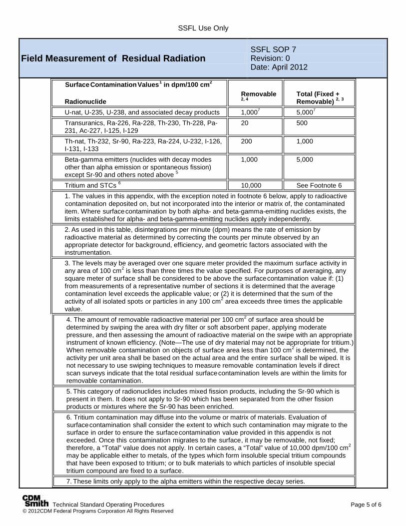
SSFL Use Only
Technical Standard Operating Procedures Page 5 of 6 © 2012CDM Federal Programs Corporation All Rights Reserved
Field Measurement of Residual Radiation SSFL SOP 7 Revision: 0 Date: April 2012
SurfaceContaminationValues1 in dpm/100 cm2
Radionuclide Removable 2, 4
Total (Fixed + Removable) 2, 3
U-nat, U-235, U-238, and associated decay products 1,0007 5,0007 Transuranics, Ra-226, Ra-228, Th-230, Th-228, Pa-231, Ac-227, I-125, I-129
20 500
Th-nat, Th-232, Sr-90, Ra-223, Ra-224, U-232, I-126, I-131, I-133
200 1,000
Beta-gamma emitters (nuclides with decay modes other than alpha emission or spontaneous fission) except Sr-90 and others noted above 5
1,000 5,000
Tritium and STCs 6 10,000 See Footnote 6 1. The values in this appendix, with the exception noted in footnote 6 below, apply to radioactive contamination deposited on, but not incorporated into the interior or matrix of, the contaminated item. Where surfacecontamination by both alpha- and beta-gamma-emitting nuclides exists, the limits established for alpha- and beta-gamma-emitting nuclides apply independently. 2. As used in this table, disintegrations per minute (dpm) means the rate of emission by radioactive material as determined by correcting the counts per minute observed by an appropriate detector for background, efficiency, and geometric factors associated with the instrumentation. 3. The levels may be averaged over one square meter provided the maximum surface activity in any area of 100 cm2 is less than three times the value specified. For purposes of averaging, any square meter of surface shall be considered to be above the surfacecontamination value if: (1) from measurements of a representative number of sections it is determined that the average contamination level exceeds the applicable value; or (2) it is determined that the sum of the activity of all isolated spots or particles in any 100 cm2 area exceeds three times the applicable value. 4. The amount of removable radioactive material per 100 cm2 of surface area should be determined by swiping the area with dry filter or soft absorbent paper, applying moderate pressure, and then assessing the amount of radioactive material on the swipe with an appropriate instrument of known efficiency. (Note—The use of dry material may not be appropriate for tritium.) When removable contamination on objects of surface area less than 100 cm2 is determined, the activity per unit area shall be based on the actual area and the entire surface shall be wiped. It is not necessary to use swiping techniques to measure removable contamination levels if direct scan surveys indicate that the total residual surfacecontamination levels are within the limits for removable contamination. 5. This category of radionuclides includes mixed fission products, including the Sr-90 which is present in them. It does not apply to Sr-90 which has been separated from the other fission products or mixtures where the Sr-90 has been enriched. 6. Tritium contamination may diffuse into the volume or matrix of materials. Evaluation of surfacecontamination shall consider the extent to which such contamination may migrate to the surface in order to ensure the surfacecontamination value provided in this appendix is not exceeded. Once this contamination migrates to the surface, it may be removable, not fixed; therefore, a “Total” value does not apply. In certain cases, a “Total” value of 10,000 dpm/100 cm2 may be applicable either to metals, of the types which form insoluble special tritium compounds that have been exposed to tritium; or to bulk materials to which particles of insoluble special tritium compound are fixed to a surface. 7. These limits only apply to the alpha emitters within the respective decay series.

SSFL Use Only
Technical Standard Operating Procedures Page 6 of 6 © 2012CDM Federal Programs Corporation All Rights Reserved
Field Measurement of Residual Radiation SSFL SOP 7 Revision: 0 Date: April 2012
[58 FR 65485, Dec. 14, 1993, as amended at 63 FR 59688, Nov. 4, 1998; 72 FR 31940, June 8, 2007; 74 FR 18116, Apr. 21, 2009]
7.0 Restrictions/Limitations Micro R and Dual Phosphor detectors are principally used for the detection of presence of radionuclides above background, not measurement devices. They are prone to breaking if the thin entrance window (found on pancake and end-window designs) is punctured. This can easily occur if the window comes in contact with a variety of objects (such as a blade of grass, paper clip, nail, and paint flecks). Once the window is broken the instrument ceases to operate and must, therefore, be returned for repair and calibration. 8.0 References Integrated Environmental Management, Inc., 1998, Measuring Radioactivity
Oak Ridge Institute for Science and Education and Radiation Emergency Assistance Center/Training Site (REAC/TS), 1992, Using a Typical Geiger-Mueller (GM) Counter to Survey
Title 10, Code of Federal Regulations, Part 835, Occupational Radiation Protection
DOE Standard Radiological Control, DOE-STD-1098-2008 with change 1 dated May 2009
DOE Order 426.2, Personnel Selection, Training, Qualification, and Certification Requirements for DOE Nuclear Facilities, 21 April 2010
DOE Standard 1107-97 with Change 1 dated November 2007, Knowledge, Skills, and Abilities for Key Radiation Protection Positions
Ludlum Measurements, Inc. Operators Manuals for Model 2241 Survey Meter with Model 19/192 Detector
Ludlum Measurements, Inc. Operators Manuals for Model 43-80 Alpha/Beta Scintillator
SSFL Use Only
Technical Standard Operating Procedures Page 1 of 4 © 2012CDM Federal Programs Corporation All Rights Reserved
Field Data Collection Documents, Content, and Control
SSFL SOP 8 Revision: 0 Date: April 2012
Prepared: D. Lange Technical Review: C. Werden
QA Review: J. Oxford Approved and Issued:
4/6/2012
Signature/Date
1.0 Objective The objective of this technical standard operating procedure (SOP) is to set criteria for content entry and form of field logbooks and SSFL Field Sample Data Sheets used for field work at the Santa Susana Field Laboratory (SSFL) site, and data entry into the Scribe database. 2.0 Background A permanently bound and consecutively paginated field logbook will be maintained daily by the CDM Smith field team in accordance with the procedures below. 2.1 Discussion Information recorded in field logbooks includes field team names, visitors, observations, data, calculations made onsite, date/time, weather, and description of the data collection activity, methods, instruments, and results. Additionally, the logbook must contain deviations from plans, observations of fill, and site features including sketches, maps, or drawings as appropriate. In addition, all SOPs will be on hand with the field sampling team. 2.2 Associated Procedures SSFL SOP 1, Procedures for Locating and Clearing Phase 3 Samples SSFL SOP 2, Surface Soil Sampling SSFL SOP 3, Subsurface Soil Sampling with Hand Auger SSFL SOP 4, Direct Push Technology Sampling SSFL SOP 5, Backhoe Trenching/Test Pits for Sample Collection SSFL SOP 9, Lithologic Logging SSFL SOP 14, Geophysical Survey SSFL SOP 15, Photographic Documentation of Field Activities SSFL SOP 16, Control of Measurement and Test Equipment 3.0 General Responsibilities Field Team Leader (FTL)–The FTL is responsible for ensuring that the format and content of data entries are in accordance with this procedure. The FTL will provide field logbooks and field data sheets to site personnel who will be responsible for their care and maintenance while in their possession. Site Geologist–The site geologist is responsible documenting site activities into the logbooks and sample data sheets as well as all sample description details. Other Site Personnel–All CDM Smith employees who make entries in field logbooks during onsite activities are required to read this procedure before engaging in this activity. Site personnel will return field logbooks to the FTL at the end of the assignment. 4.0 Required Equipment Site-specific plans (Field Sampling Plan [FSP]
Addendum, health and safety plan) Indelible black or blue ink pen
Field logbook SSFL Field Sample Data Sheet (FSDS) Scribe Version 3.8 (or later)
SSFL Use Only
Technical Standard Operating Procedures Page 2 of 4 © 2012CDM Federal Programs Corporation All Rights Reserved
Field Data Collection Documents, Content, and Control
SSFL SOP 8 Revision: 0 Date: April 2012
5.0 Procedures 5.1 Preparation In addition to this SOP, site personnel responsible for maintaining logbooks must be familiar with all procedures applicable to the field activity being performed. These procedures should be consulted as necessary to obtain specific information about equipment and supplies, health and safety, sample collection, packaging, decontamination, and documentation. These procedures should be located at the field office or vehicle for easy reference. Field logbooks are bound, with lined and consecutively numbered pages. All markings and notes will be made with indelible black or blue ink pen. All pages must be numbered before initial use of the logbook. Before use in the field, the FTL will title and sequentially number each logbook, and ensure the pages are sequentially numbered and the table of contents (TOC) is set up. Record the following information on the cover of the logbook: Field logbook number (if applicable). Start date of entries. Site name and location. End date of entries. Activity (if the logbook is to be activity-specific). Name of CDM Smith contact and phone number(s)
(typically the project manager). The first few (approximately two) pages of the logbook will be reserved for a TOC. Mark the first page with the heading “Table of Contents” and enter the following: Table of Contents Date/Description Pages (Start Date)/Reserved for TOC 1-2 The remaining pages of the TOC will also be designated as such with “Table of Contents” written on the top center of each page. The TOC should be completed as activities are completed and before returning the logbook back to the FTL. 5.2 Log Book Requirements Documentation requirements for logbooks are: Record work, observations, quantity of materials, field calculations and drawings, and related information directly in the
logbook. If data collection forms are specified by an activity-specific plan, this information does not need to be duplicated in the logbook. However, forms (e.g., SSFL-Field Sample Data Sheets) used to record site information must be referenced in the logbook.
Do not start a new page until the previous one is full or has been marked with a single diagonal line so that additional entries cannot be made. Use both sides of each page.
Do not erase or blot out any entry at any time. Indicate any deletion by a single line through the material to be deleted. Initial and date each deletion. Take care to not obliterate what was written previously.
Do not remove any pages from the book. Specific requirements for field logbook entries include: Initial and date each page. Sign and date the final page of entries for each day. Initial and date all changes. If authors change within the course of the day, the original author must insert the following: Above notes authored by: - (Sign name) - (Print name) - (Date) The new author must sign and print his/her name before additional entries are made. Draw a diagonal line through the remainder of the final page at the end of the day.

SSFL Use Only
Technical Standard Operating Procedures Page 3 of 4 © 2012CDM Federal Programs Corporation All Rights Reserved
Field Data Collection Documents, Content, and Control
SSFL SOP 8 Revision: 0 Date: April 2012
Record the following information on a daily basis: -Date and time -Name of individual making entry -Names of field team and other persons onsite -Description of activity being conducted including station or location (i.e., boring, sampling location number) if appropriate -Weather conditions (i.e., temperature, cloud cover, precipitation, wind direction and speed) and other pertinent data -Level of personal protection used -Serial numbers of instruments -Equipment calibration information (initial and ongoing date and time activity) -Serial/tracking numbers on documentation (e.g., carrier air bills)
Entries into the field logbook shall be preceded with the time (written in military units) of the observation. The time should be recorded frequently and at the point of events or measurements that are critical to the activity being logged. All measurements made and samples collected must be recorded. A sketch of station location may be warranted. All maps or sketches made in the logbook should have descriptions of the features shown and a direction indicator. Other events and observations that should be recorded include: Changes in weather that impact field activities. Deviations from procedures outlined in any governing documents. Also, record the reason for any noted deviation. Problems, downtime, or delays. Upgrade or downgrade of personal protection equipment. Visitors to the site. 5.3 Field Sample Data Sheets An example Field Sample Data Sheet (FSDS) that will be use to record the sample details and subsurface conditions is
included as Attachment 1 to SOP 8. The FSDS will be completed by the Site Geologist from observations of the soil core, cuttings, and sidewalls of trenches
and test pits. The FSDS is a single page, double-sided form that will be completed in indelible ink. All portions of the form will be completed. If any portion is not applicable to the activity being recorded, that portion will
be crossed out with a single line and initialed by the Site Geologist. The FSDS must be reviewed and signed by another field team member before being copied into a pdf file. The pdf file will be transferred to CDM’s main database weekly by the Site Geologist. The original of the FSDS will be
maintained in a binder at the site office until completion of all field activities. Sample description information (sample characteristics, presence of fill, staining, odor, etc.) will be transferred to the
electronic database on a weekly basis by the Site Geologist or his/her designee. Copies of the FSDS documents will be included in the data report presenting the findings of the investigation. This form will be kept as a quality record in the project file for period stated in the Administrative Order on Consent. 5.4 Scribe Database Requirements The Scribe will be used to capture the data from the FSDS and performs the following tasks at a minimum:
Document Field Sample Collection Generate Chain of Custody Forms Track Field Samples to Laboratories Query Database and Produce Reports
The FSDS information is entered into the field database, Scribe. The Scribe data entry is reviewed by another staff. The Scribe database is backed up daily off-site to CDM Smith servers. In the event of internet outages, the backups will
be made to an external device such as an external hard-drive, thumb drive or CD/DVD. Once internet service is
SSFL Use Only
Technical Standard Operating Procedures Page 4 of 4 © 2012CDM Federal Programs Corporation All Rights Reserved
Field Data Collection Documents, Content, and Control
SSFL SOP 8 Revision: 0 Date: April 2012
restored the most current backup will be used and placed on the CDM Smith servers. Changes to the finalized FSDS are documented on the FSDS and Scribe. 5.5 Photographs Photography is restricted at SSFL. All cameras require permits from The Boeing Company (Boeing) to be onsite. Photographs may be taken at the site to visually document field activities and site features, as needed and in accordance with SSFL SOP 15. Digital photographs will be submitted to the electronic project files. All digital photographs will be documented on a photographic log in the logbook or on a separate form (reference in the logbook). Captions must be added to the file name after the photographs are downloaded. The caption should be a unique identifier – number or date and short description. The photographic log should contain the following information: Photograph sequence number Description of activity/item shown (e.g., SSFL and sampling activity) Date and time Direction (if applicable) Name of photographer 5.6 Post-Operation To guard against loss of data as a result of damage or disappearance of logbooks, photocopy completed pages daily and forward to the field or project office weekly (at a minimum). Photocopy other field records (e.g., Field Sample Data Sheets, photographic logs) weekly and submit to the field or project office weekly (at a minimum), or as requested. At the conclusion of each day, the individual responsible for the logbook will ensure that all entries have been appropriately signed and dated and that corrections were made properly (single lines drawn through incorrect information then initialed and dated). Completed logbooks will be returned to the FTL. 6.0 Restrictions/Limitations Field logbooks constitute the official record of onsite technical work, investigations, and data collection activities. Their use, control, and ownership are restricted to activities pertaining to specific field operations carried out by CDM Smith personnel and their subcontractors. They may be used in court to indicate dates, personnel, procedures, and techniques employed during site activities. Entries made in these logbooks should be factual, clear, precise, and non-subjective. Field logbooks, and entries within, are not to be used for personal use. 7.0 References No references used. 8.0 Attachments Attachment A – SSFL Phase 3 – Field Sample Data Sheet
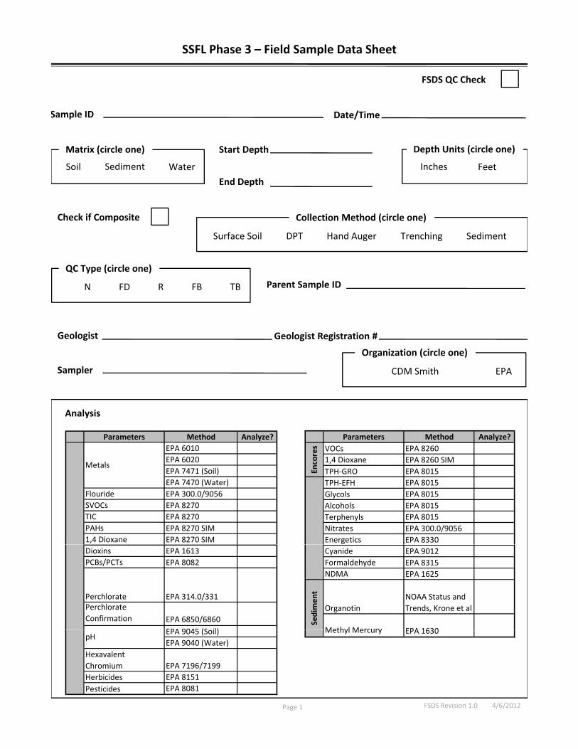
Sample ID Date/Time
SSFL Phase 3 – Field Sample Data Sheet
FSDS QC Check
p /
Soil Water
Start Depth
End Depth
Inches Feet
Matrix (circle one) Depth Units (circle one)
Sediment
Check if Composite
Parent Sample ID
DPT Trenching
FD TBR FBN
Hand Auger
QC Type (circle one)
Collection Method (circle one)
Surface Soil Sediment
Sampler
p
Geologist Geologist Registration #
FD TBR FBN
CDM Smith EPA
Organization (circle one)
p CDM Smith EPA
Analysis
Parameters Method Analyze?EPA 6010EPA 6020
Parameters Method Analyze?VOCs EPA 8260 1 4 Dioxane EPA 8260 SIMor
es
EPA 6020EPA 7471 (Soil) EPA 7470 (Water)
Flouride EPA 300.0/9056SVOCs EPA 8270TIC EPA 8270 PAHs EPA 8270 SIM1,4 Dioxane EPA 8270 SIM
Metals1,4 Dioxane EPA 8260 SIMTPH‐GRO EPA 8015TPH‐EFH EPA 8015Glycols EPA 8015Alcohols EPA 8015Terphenyls EPA 8015Nitrates EPA 300.0/9056Energetics EPA 8330
Enco
Dioxins EPA 1613PCBs/PCTs EPA 8082
Perchlorate EPA 314.0/331Perchlorate Confirmation EPA 6850/6860
EPA 9045 (S il)
Cyanide EPA 9012Formaldehyde EPA 8315NDMA EPA 1625
OrganotinNOAA Status and Trends, Krone et al
Methyl Mercury EPA 1630
Sedimen
t
FSDS Revision 1.0 4/6/2012
EPA 9045 (Soil)EPA 9040 (Water)
Hexavalent Chromium EPA 7196/7199Herbicides EPA 8151Pesticides EPA 8081
pH Methyl Mercury EPA 1630
Page 1
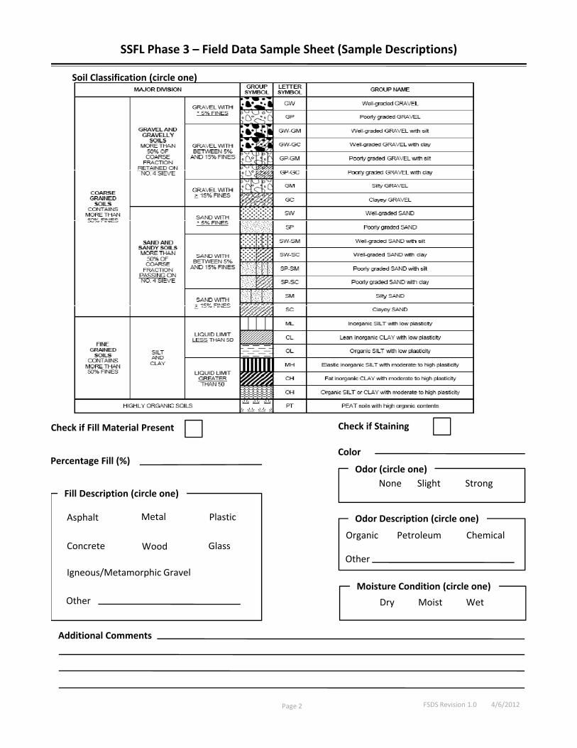
Soil Classification (circle one)
SSFL Phase 3 – Field Data Sample Sheet (Sample Descriptions)
Color
Check if Fill Material Present
P t Fill (%)
Check if Staining
Percentage Fill (%)
StrongNone SlightOdor (circle one)
Organic Petroleum
Odor Description (circle one)
Chemical
Fill Description (circle one)
Asphalt
C t
Metal Plastic
W d Gl
WetDry Moist
Moisture Condition (circle one)
OtherConcrete
Igneous/Metamorphic Gravel
Wood Glass
Other
Additional Comments
Page 2 FSDS Revision 1.0 4/6/2012
SSFL Use Only
Technical Standard Operating Procedures Page 1 of 9 © 2012 CDM Federal Programs Corporation All Rights Reserved
Lithologic Logging SSFL SOP 9 Revision: 0 Date: April 2012
Prepared: D. Lange Technical Review: C. Werden
QA Review: J. Oxford Approved and Issued:
4/6/2012
Signature/Date
1.0 Objective This technical standard operating procedure (SOP) governs basic lithologic logging of surface and subsurface soil samples collected during field operations at the Santa Susana Field Laboratory (SSFL) site. The purpose of this SOP is to present a protocol and standardized documentation format for lithologic observations. Protocols for recording basic lithologic data including, but not limited to, soil types (per the Unified Soil Classification System [USCS] classification), presence of fill (and associated deleterious materials), lithologic names, color, moisture, density, contacts, and secondary features such as organic material and fractures. The goal of this SOP is to have consistent descriptions of the subsurface materials. 2.0 Background Thousands of boreholes and associated descriptions of the surface and subsurface soil and rock have been completed at the SSFL site. Lithologic information about soil, rock, and fill assists in the understanding of subsurface conditions, moisture infiltration, groundwater flow, and potential contaminant migration pathways. 2.1 Definitions The following list corresponds to the description sequences outlined in Section 5.2.1. An example lithologic log is included in Attachment A. Name of Sediment or Rock – In naming unconsolidated sediments, the logger shall describe the grain size, distribution, color, and moisture content, and determine the presence of fill materials. In naming sedimentary rocks (only type of bedrock anticipated at SSFL), the logger shall examine the specimen for mineralogy and use the appropriate rock description. Color - Color may be determined using the appropriate Munsell color chart (soil or rock) and listing the Munsell number that corresponds to the color. If an unconsolidated material is mottled in color, the ranges in color shall be described. When describing core samples with several individual colors, individual color names shall be listed and an overall best color name shall be given. Degree of Consolidation – The degree of consolidation refers to how well the material has been indurated. Unconsolidated sediments may be compacted somewhat and should be described as loose, moderately compacted, or strongly compacted. In some cases they may be slightly cemented by caliche and should be described as slightly cemented, moderately cemented, or strongly cemented. Sedimentary rocks are typically indurated, but may vary in the degree of cementation. These rocks should be described as friable, moderately friable, or well indurated. If the logger believes he/she can identify the cementing material, then it shall be included in the description. Moisture Content – Moisture content refers to the amount of water within the sediment or the matrix. Sedimentary rocks and unconsolidated sediments may have associated moisture within and should be described as dry, slightly moist, medium moist, moist, wet (not flowing), or saturated (flowing water). Evidence of Contamination – The logger should examine the sample/core and note any obvious signs of contamination such as streaking, free product, odor, or discoloration. These observations will be noted in the field book and on the lithologic log, as well as screening measurements from the photoionization detector (PID) and radiation (alpha, beta) probes. Description of Contacts – The logger will note changes in lithology. These changes may be gradational contacts within sediments or may be sharp contacts such as sediments over rocks. The logger should describe whether the contacts are
SSFL Use Only
Technical Standard Operating Procedures Page 2 of 9 © 2012 CDM Federal Programs Corporation All Rights Reserved
Lithologic Logging SSFL SOP 9 Revision: 0 Date: April 2012
gradational or sharp, and note the depth below the surface. Composition – The composition of the rock refers to the mineralogy of the material encountered. The logger should describe the mineralogy, if it can be determined. 2.2 Associated Procedures SSFL SOP 2, Surface Soil Sampling SSFL SOP 3, Subsurface Soil Sampling with Hand Auger SSFL SOP 4, Direct Push Technology Sampling SSFL SOP 5, Backhoe Trenching/Test Pits for Sample Collection SSFL SOP 8, Field Data Collection Documents, Content, and Control 2.3 Discussion The subsurface sampling techniques used at SSFL (i.e., slide hammer, hand auger, DPT rigs, and trenching) all result in soil/rock being brought to the surface for description and logging. The soil boring, core retrieval, and lithologic logging will be conducted under the guidance of a California professional geologist, or other earth scientist under a geologist’s supervision. An important aspect of soil sampling is the identification and differentiation of native soil/rock from fill material. To help in this task, it is important to use the USCS classification scheme, and uniform and consistent descriptions. Soil and rock descriptions will be consistent with ASTM 2488-06 (Standard Practice for Description and Identification of Soils – Visual Manual Procedure). This SOP also provides a sequence for recording information on a standardized log form to make descriptions as uniform and consistent as possible. The local geology of SSFL is well characterized; thousands of shallow boreholes and excavations have been completed. Local soil and rock are well documented. As such, detailed lithologic logs are not necessary. The primary goal of lithologic logging is to document the stratigraphic sequence, the presence of fill or native soil, occurrence and type of debris and/or staining, associated PID and radiological screening values, and deviations from the normal or anticipated stratigraphic section. In addition, all SOPS will be on hand with the field sampling crew. 3.0 General Responsibilities Field Team Leader (FTL) – The FTL is responsible for maintaining logbooks and qualified field staff. Site Geologist – Individual responsible for describing and logging of all soil cuttings/samples and all rock per this SOP. A California professional geologist is required to lead this project work. 4.0 Required Equipment The description of subsurface lithologies requires a minor amount of field equipment for the geologist. This section provides a list of equipment to be used by the lithologic logger but does not include equipment such as drill rigs, PID, sampling equipment, and personal protection equipment. The following is a general list of equipment that may be used: Field logbook and lithologic log form Waterproof pens Clipboard 10x magnifying hand lens Munsell color chart for soil Knife or cutting tool Munsell color chart for rock Dilute (10 percent) hydrochloric acid, as desired
Zip-top baggies Reference field charts, as desired
5.0 Procedures 5.1 Office Obtain field logbook and lithologic log forms Coordinate schedules/actions with FTL Obtain necessary field equipment (see above)
SSFL Use Only
Technical Standard Operating Procedures Page 3 of 9 © 2012 CDM Federal Programs Corporation All Rights Reserved
Lithologic Logging SSFL SOP 9 Revision: 0 Date: April 2012
Review field support documents (i.e., Field Sampling Plan [FSP] Addendum, health and safety plan) Review applicable geologic references such as historic lithologic logs from the site and/or geologic maps, as needed 5.1.1 Documentation Record observations in a bound field logbook (SSFL SOP 8) and/or on individual lithologic log forms. Site geologists (i.e., lithologic loggers) will follow the general procedures for keeping a field logbook. If using a bound field logbook, record the same data required on the lithologic log form. Data from the field logbook must be transcribed to the lithologic log form if filling in the form in the field is not feasible. In this case, the data must be the identical to those recorded in the field logbook. Post-logging editing of field logbook data is not allowed. In addition, if data are transcribed to the lithologic log form, it must be completed within 24 hours of the original data recording. All blanks in the lithologic log form must be filled out; if an item is not applicable, an “NA” shall be entered. The Lithologic Log Form shall be filled out according to the following instructions. The front page of the form contains general information: The project name, sample location, subarea, and sample type Date that the drilling activity was started and completed Name of the person logging along with the beginning depth-end depth (in feet) Borehole diameter(s) and drilling methods Name and company of the driller and the type of sampling tool used A map showing the soil sampling location may be attached.
The continuation page(s) of the log form should be completed according to the instructions provided within this section and according to the sequence provided in Section 5.2.1. The depth column refers to the depth below ground surface (bgs) in feet. The tick marks can be arbitrarily set to any depth interval depending on the scale needed except where client requirements dictate the spacing. The lithology column shall contain the USCS soil type/rock type; schematic symbols are not required. Use a single X to mark the area where no core was recovered, and notes shall be recorded as to why the section was not recovered. Sharp or abrupt contacts between lithologies will be indicated by a solid horizontal line. Gradational changes in lithologic composition should be noted. PID and radiation measurements will be recorded within the PID column at the appropriate depth. The description column, where the lithology is described, is the most important part of the lithologic log. In completing this section, use the applicable reference charts and complete according to the sequence in Section 5.2.1. The sample interval column is reserved for noting any samples taken and processed for the laboratory. The sample number shall be filled in at the appropriate depth. The last column refers to the percent core recovery. The geologist will estimate the amount recovered and record the percentage at the appropriate depth. In addition to the information on the log form, the geologist will record the appropriate information into the logbook when there is a rig shutdown, rig problems, failures to recover cores, or other issues. 5.2 General Guidelines for Using and Supplementing Lithologic Descriptive Protocols This SOP is intended to serve as a guide for recording basic lithologic information. The descriptive protocol presented here must be followed in making basic observations. Selected information charts may be used for classification and naming of rock, sediment, and soil. Some observations will be common to all rock and soil descriptions. All descriptions shall include as appropriate: name of sediment or rock, color (using the Munsell color charts), moisture content, composition, significant inclusions, and degree of consolidation or induration, and the presence and type of fill materials, if identified. The description of each category shall be separated by a semicolon. Any interpretive comments will be segregated from lithologic descriptions and recorded in the remarks column. Describe all unconsolidated sediment and soil according to the USCS. It is often more practical to use abbreviations for often-repeated terminology when recording lithologic descriptions. Abbreviations are allowed; however, the abbreviation and its meaning must be recorded on the lithologic log the first time it is used, or listed at the bottom the log. Loggers are cautioned to limit the use of abbreviations to avoid a lithologic log that is cryptic.
SSFL Use Only
Technical Standard Operating Procedures Page 4 of 9 © 2012 CDM Federal Programs Corporation All Rights Reserved
Lithologic Logging SSFL SOP 9 Revision: 0 Date: April 2012
5.2.1 Protocols for Lithologic Description of Discrete Soil or Rock Cores This section describes the protocols for completing a lithologic description based on discrete soil or rock core samples. For instance, in a 5-foot soil core, the dominant lithology may be siltstone that is interrupted by several thin beds of another lithology such as gravel. This section description can be simplified by writing: 5-10 bgs = siltstone (with other descriptors) except as noted; 7-8 foot gravel zone (with descriptors); 8-9 foot pebble zone (with descriptors); etc. This also aids in “seeing” the thickest unit designations possible for use in modeling. Description of Unconsolidated Material Unconsolidated material comprises the majority of the subsurface interval for the Phase 3 investigation. The shallow subsurface is very important to the chemical characterization because of infiltration and migration. Soils are to be described as unconsolidated material and will include: Name of sediment (sand, silt, clay, etc.) Degree of consolidation and cementation Grain size and distribution Moisture content Composition of larger-grained sediments Density Color (per Munsell color chart) Description of contacts In accordance with the USCS on naming unconsolidated sediment, the particle size with the highest percentage is the root name. When additional grains are present in excess of 15 percent, the root name is modified by adding a term in front of the root name. For instance, if a material is 80 percent sand and 20 percent gravel, then it is gravelly sand. If the subordinate grains comprise less than 15 percent but greater than 5 percent, the name is written: ____________________(dominant grain) with ________________(subordinate grain). For example, a soil with 90 percent sand and 10 percent silt would be named a sand with silt. If a soil contains greater than 15 percent of four particle sizes, then the name is comprised of the dominant grain size as the root name and modifiers as added before. For example, if a material is 60 percent sand, 20 percent silt, and 20 percent clay the name would be a silty clayey sand. If a material is 70 percent sand, 20 percent silt, and 10 percent clay, it would be a silty sand with clay. When large cobbles or boulders are present, their percentage shall be estimated and their mineralogy recorded. 6.0 Restrictions/Limitations Only geologists, or similarly qualified persons trained in lithologic description, are qualified to perform the duties described in this SOP. The FTL for a project will have the authority to decide whether or not an individual is qualified. 7.0 References ASTM 2488-06 Standard Practice for Description and Identification of Soils – Visual Manual Procedure 8.0 Attachments Note: These Attachments are for informational purposes. Other equivalent charts such as USCS or logs may be used. Attachment A - Lithologic Logs Attachment B - Common Abbreviations for Lithologic Logging Attachment C - Naming of Unconsolidated Materials Attachment D - Example of Unified Soil Classification System (USCS)
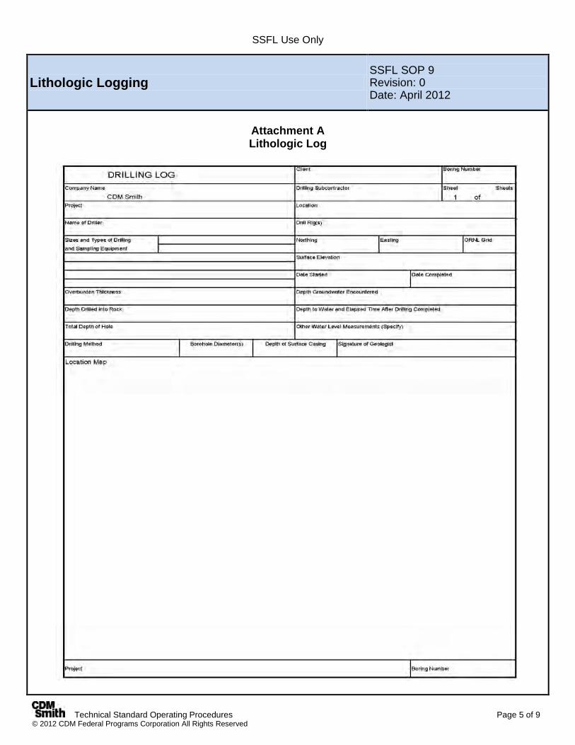
SSFL Use Only
Technical Standard Operating Procedures Page 5 of 9 © 2012 CDM Federal Programs Corporation All Rights Reserved
Lithologic Logging SSFL SOP 9 Revision: 0 Date: April 2012
Attachment A Lithologic Log
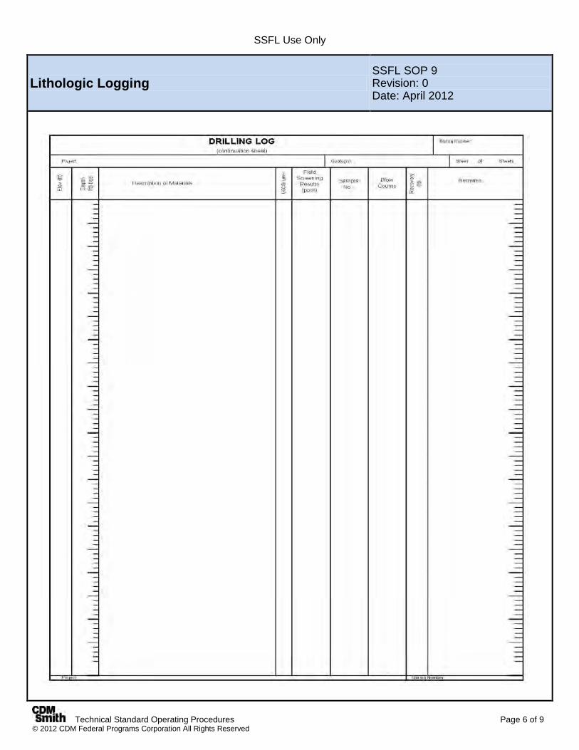
SSFL Use Only
Technical Standard Operating Procedures Page 6 of 9 © 2012 CDM Federal Programs Corporation All Rights Reserved
Lithologic Logging SSFL SOP 9 Revision: 0 Date: April 2012
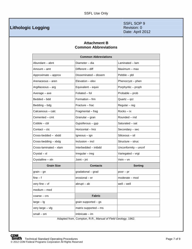
SSFL Use Only
Technical Standard Operating Procedures Page 7 of 9 © 2012 CDM Federal Programs Corporation All Rights Reserved
Lithologic Logging SSFL SOP 9 Revision: 0 Date: April 2012
Attachment B
Common Abbreviations
Common Abbreviations
Abundant – abnt Diameter – dia Laminated – lam
Amount – amt Different – diff Maximum – max
Approximate – approx Disseminated – dissem Pebble – pbl
Arenaceous – aren Elevation – elev Phenocryst – phen
Argillaceous – arg Equivalent – equiv Porphyritic – proph
Average – ave Foliated – fol Probable – prob
Bedded – bdd Formation – frm Quartz – qrz
Bedding – bdg Fracture – frac Regular – reg
Calcareous – calc Fragmental – frag Rocks – rx
Cemented – cmt Granular – gran Rounded – rnd
Cobble – cbl Gypsiferous – gyp Saturated – sat
Contact – ctc Horizontal – hriz Secondary – sec
Cross-bedded – xbdd Igneous – ign Siliceous – sil
Cross-bedding – xbdg Inclusion – incl Structure – struc
Cross-laminated – xlam Interbedded – intbdd Unconformity – uncnf
Crystal – xl Irregular – ireg Variegated – vrgt
Crystalline – xln Joint – jnt Vein – vn
Grain Size Contacts Sorting
grain – gn gradational – grad poor – pr
fine – f erosional – er moderate – mod
very fine – vf abrupt – ab well – well
medium – med
coarse – crs Fabric
large – lg grain supported – gs
very large – vlg matrix supported – ms
small – sm imbricate – im Adapted from, Compton, R.R., Manual of Field Geology, 1962.
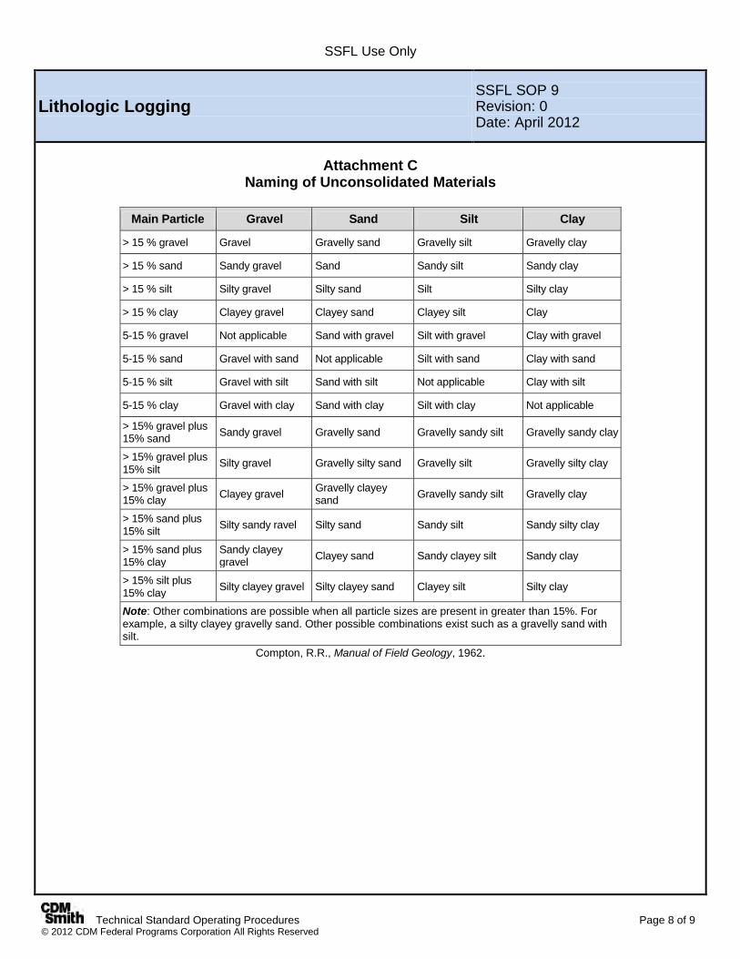
SSFL Use Only
Technical Standard Operating Procedures Page 8 of 9 © 2012 CDM Federal Programs Corporation All Rights Reserved
Lithologic Logging SSFL SOP 9 Revision: 0 Date: April 2012
Attachment C
Naming of Unconsolidated Materials
Main Particle Gravel Sand Silt Clay
> 15 % gravel Gravel Gravelly sand Gravelly silt Gravelly clay
> 15 % sand Sandy gravel Sand Sandy silt Sandy clay
> 15 % silt Silty gravel Silty sand Silt Silty clay
> 15 % clay Clayey gravel Clayey sand Clayey silt Clay
5-15 % gravel Not applicable Sand with gravel Silt with gravel Clay with gravel
5-15 % sand Gravel with sand Not applicable Silt with sand Clay with sand
5-15 % silt Gravel with silt Sand with silt Not applicable Clay with silt
5-15 % clay Gravel with clay Sand with clay Silt with clay Not applicable
> 15% gravel plus 15% sand Sandy gravel Gravelly sand Gravelly sandy silt Gravelly sandy clay
> 15% gravel plus 15% silt Silty gravel Gravelly silty sand Gravelly silt Gravelly silty clay
> 15% gravel plus 15% clay Clayey gravel Gravelly clayey
sand Gravelly sandy silt Gravelly clay
> 15% sand plus 15% silt Silty sandy ravel Silty sand Sandy silt Sandy silty clay
> 15% sand plus 15% clay
Sandy clayey gravel Clayey sand Sandy clayey silt Sandy clay
> 15% silt plus 15% clay Silty clayey gravel Silty clayey sand Clayey silt Silty clay
Note: Other combinations are possible when all particle sizes are present in greater than 15%. For example, a silty clayey gravelly sand. Other possible combinations exist such as a gravelly sand with silt.
Compton, R.R., Manual of Field Geology, 1962.
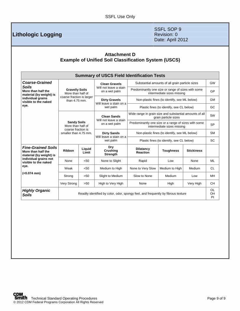
SSFL Use Only
Technical Standard Operating Procedures Page 9 of 9 © 2012 CDM Federal Programs Corporation All Rights Reserved
Lithologic Logging SSFL SOP 9 Revision: 0 Date: April 2012
Attachment D
Example of Unified Soil Classification System (USCS)
Summary of USCS Field Identification Tests
Coarse-Grained Soils More than half the material (by weight) is individual grains visible to the naked eye.
Gravelly Soils More than half of
coarse fraction is larger than 4.75 mm.
Clean Gravels Will not leave a stain
on a wet palm
Substantial amounts of all grain particle sizes GW
Predominantly one size or range of sizes with some intermediate sizes missing GP
Dirty Gravels Will leave a stain on a
wet palm
Non-plastic fines (to identify, see ML below) GM
Plastic fines (to identify, see CL below) GC
Sandy Soils More than half of coarse fraction is
smaller than 4.75 mm.
Clean Sands Will not leave a stain
on a wet palm
Wide range in grain size and substantial amounts of all grain particle sizes SW
Predominantly one size or a range of sizes with some intermediate sizes missing SP
Dirty Sands Will leave a stain on a
wet palm
Non-plastic fines (to identify, see ML below) SM
Plastic fines (to identify, see CL below) SC
Fine-Grained Soils More than half the material (by weight) is individual grains not visible to the naked eye. (<0.074 mm)
Ribbon Liquid Limit
Dry Crushing Strength
Dilatancy Reaction Toughness Stickiness
None <50 None to Slight Rapid Low None ML
Weak <50 Medium to High None to Very Slow Medium to High Medium CL
Strong >50 Slight to Medium Slow to None Medium Low MH
Very Strong >50 High to Very High None High Very High CH
Highly Organic Soils Readily identified by color, odor, spongy feel, and frequently by fibrous texture
OL OH Pt
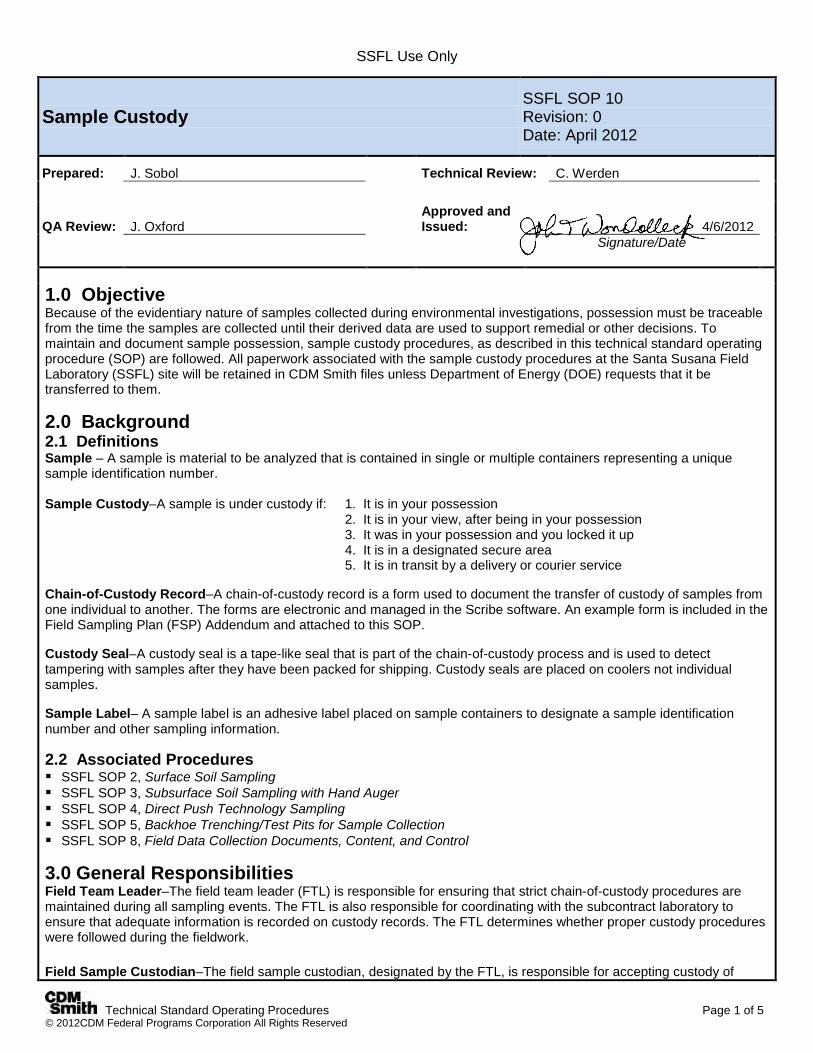
SSFL Use Only
Technical Standard Operating Procedures Page 1 of 5 © 2012CDM Federal Programs Corporation All Rights Reserved
Sample Custody SSFL SOP 10 Revision: 0 Date: April 2012
Prepared: J. Sobol Technical Review: C. Werden
QA Review: J. Oxford Approved and Issued:
4/6/2012
Signature/Date
1.0 Objective Because of the evidentiary nature of samples collected during environmental investigations, possession must be traceable from the time the samples are collected until their derived data are used to support remedial or other decisions. To maintain and document sample possession, sample custody procedures, as described in this technical standard operating procedure (SOP) are followed. All paperwork associated with the sample custody procedures at the Santa Susana Field Laboratory (SSFL) site will be retained in CDM Smith files unless Department of Energy (DOE) requests that it be transferred to them.
2.0 Background 2.1 Definitions Sample – A sample is material to be analyzed that is contained in single or multiple containers representing a unique sample identification number. Sample Custody–A sample is under custody if: 1. It is in your possession 2. It is in your view, after being in your possession 3. It was in your possession and you locked it up 4. It is in a designated secure area 5. It is in transit by a delivery or courier service Chain-of-Custody Record–A chain-of-custody record is a form used to document the transfer of custody of samples from one individual to another. The forms are electronic and managed in the Scribe software. An example form is included in the Field Sampling Plan (FSP) Addendum and attached to this SOP. Custody Seal–A custody seal is a tape-like seal that is part of the chain-of-custody process and is used to detect tampering with samples after they have been packed for shipping. Custody seals are placed on coolers not individual samples. Sample Label– A sample label is an adhesive label placed on sample containers to designate a sample identification number and other sampling information. 2.2 Associated Procedures SSFL SOP 2, Surface Soil Sampling SSFL SOP 3, Subsurface Soil Sampling with Hand Auger SSFL SOP 4, Direct Push Technology Sampling SSFL SOP 5, Backhoe Trenching/Test Pits for Sample Collection SSFL SOP 8, Field Data Collection Documents, Content, and Control 3.0 General Responsibilities Field Team Leader–The field team leader (FTL) is responsible for ensuring that strict chain-of-custody procedures are maintained during all sampling events. The FTL is also responsible for coordinating with the subcontract laboratory to ensure that adequate information is recorded on custody records. The FTL determines whether proper custody procedures were followed during the fieldwork. Field Sample Custodian–The field sample custodian, designated by the FTL, is responsible for accepting custody of
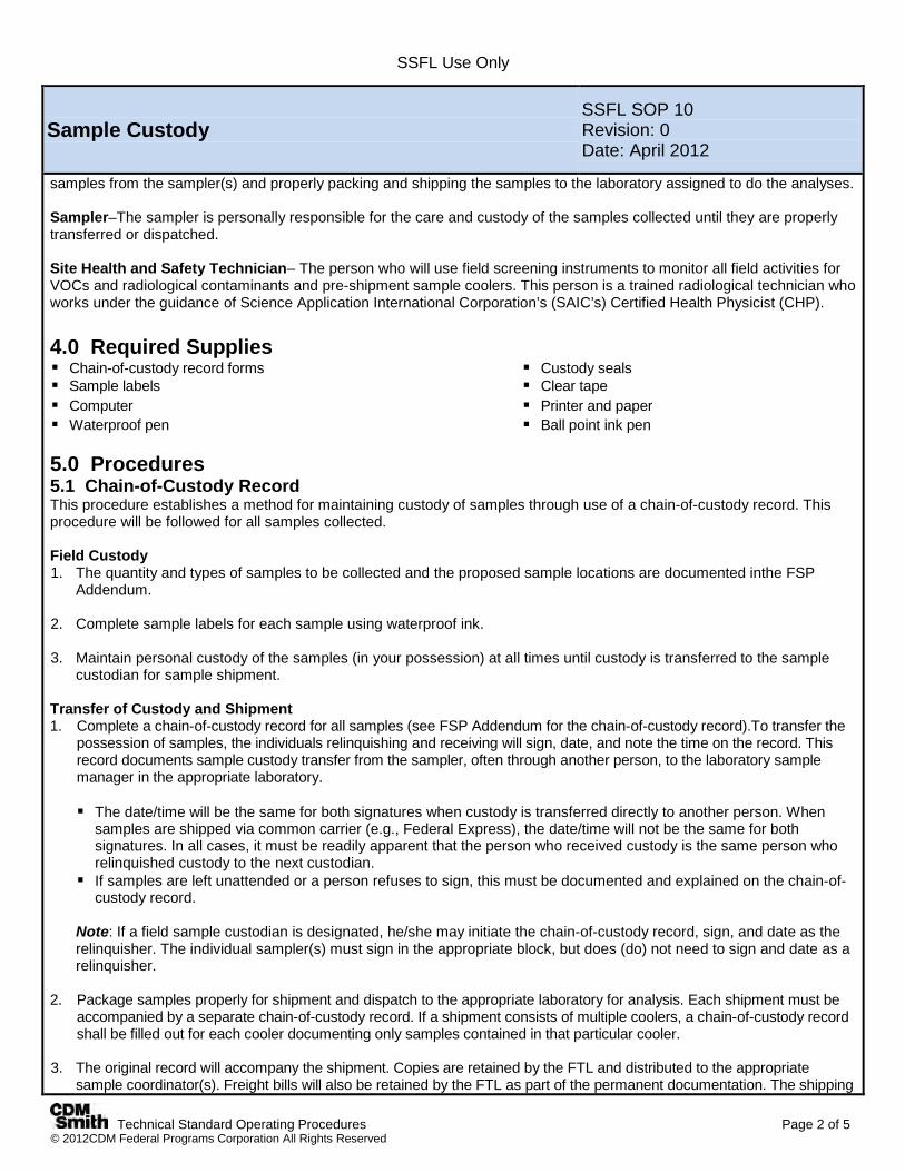
SSFL Use Only
Technical Standard Operating Procedures Page 2 of 5 © 2012CDM Federal Programs Corporation All Rights Reserved
Sample Custody SSFL SOP 10 Revision: 0 Date: April 2012
samples from the sampler(s) and properly packing and shipping the samples to the laboratory assigned to do the analyses. Sampler–The sampler is personally responsible for the care and custody of the samples collected until they are properly transferred or dispatched. Site Health and Safety Technician– The person who will use field screening instruments to monitor all field activities for VOCs and radiological contaminants and pre-shipment sample coolers. This person is a trained radiological technician who works under the guidance of Science Application International Corporation’s (SAIC’s) Certified Health Physicist (CHP). 4.0 Required Supplies Chain-of-custody record forms Custody seals Sample labels Clear tape Computer Printer and paper Waterproof pen Ball point ink pen 5.0 Procedures 5.1 Chain-of-Custody Record This procedure establishes a method for maintaining custody of samples through use of a chain-of-custody record. This procedure will be followed for all samples collected. Field Custody 1. The quantity and types of samples to be collected and the proposed sample locations are documented inthe FSP
Addendum. 2. Complete sample labels for each sample using waterproof ink. 3. Maintain personal custody of the samples (in your possession) at all times until custody is transferred to the sample
custodian for sample shipment. Transfer of Custody and Shipment 1. Complete a chain-of-custody record for all samples (see FSP Addendum for the chain-of-custody record).To transfer the
possession of samples, the individuals relinquishing and receiving will sign, date, and note the time on the record. This record documents sample custody transfer from the sampler, often through another person, to the laboratory sample manager in the appropriate laboratory.
The date/time will be the same for both signatures when custody is transferred directly to another person. When
samples are shipped via common carrier (e.g., Federal Express), the date/time will not be the same for both signatures. In all cases, it must be readily apparent that the person who received custody is the same person who relinquished custody to the next custodian.
If samples are left unattended or a person refuses to sign, this must be documented and explained on the chain-of-custody record.
Note: If a field sample custodian is designated, he/she may initiate the chain-of-custody record, sign, and date as the relinquisher. The individual sampler(s) must sign in the appropriate block, but does (do) not need to sign and date as a relinquisher.
2. Package samples properly for shipment and dispatch to the appropriate laboratory for analysis. Each shipment must be
accompanied by a separate chain-of-custody record. If a shipment consists of multiple coolers, a chain-of-custody record shall be filled out for each cooler documenting only samples contained in that particular cooler.
3. The original record will accompany the shipment. Copies are retained by the FTL and distributed to the appropriate
sample coordinator(s). Freight bills will also be retained by the FTL as part of the permanent documentation. The shipping

SSFL Use Only
Technical Standard Operating Procedures Page 3 of 5 © 2012CDM Federal Programs Corporation All Rights Reserved
Sample Custody SSFL SOP 10 Revision: 0 Date: April 2012
number from the freight bill shall be recorded on the applicable chain-of-custody record and field logbook in accordance with SSFL SOP 8).
Procedure for Completing Chain-of-Custody Record The following procedure is used to fill out the SSFL chain-of-custody record. The custody record must be filled out in its entirety. Chain-of-custody forms will be computer-generated. Review the form to ensure all information boxes are completed. Example custody record information includes: Chain of Custody Title Information 1. Record site, project code, and cooler number. 2. Record the name and address of the laboratory where the samples are being shipped, and the lab contact’s name. 3. Record the date shipped, overnight courier’s name, and airbill number.
Project code (i.e., project or task number).
Sample Record Information 1. Record the sample number. 2. Record the matrix and sample personnel names. 3. Record the sample collection method. 4. Record the analysis and turnaround time. 5. Record the preservative and number and type of bottles; the “tag” field will not be used. 6. Record the station location. 7. Enter time of sample collection in military time. 8. List any special instructions. Also, note which samples may have high concentrations as advanced notice for the
laboratory. 9. Record if the shipment case is complete. 10. Sign the chain-of-custody record(s) in the space provided. List the title and company of the Relinquisher. All samplers
must sign each record. 5.2 Sample Labels Sample labels will be used for all samples collected at the SSFL site. 1. Complete one label with the following information for each sample container collected:
Station number (sample identification number). Date (i.e., month, day, and year of collection). Time (i.e., military) of sample collection. Mark to indicate soil or water sample. Sampler will place their initial in the space provided. List preservative type. List or mark the “Analyses” for which the sample is to be analyzed. If the desired analysis is not listed, write it in the
empty slot. Note: Do not write in the box for “laboratory sample number.” Place or write additional relevant information under “Remarks.”
2. Place adhesive labels directly on the sample containers so that the label is completely below the lid of the container.
Place clear tape over the label to protect from moisture. Note: The EnCore sampler is very small; therefore, the sample label is placed on the zip-top bag that contains the samplers 3. Double-check that the information recorded on the sample label is consistent with the information recorded on the chain-
of-custody record. 5.3 Custody Seals Two custody seals must be placed on opposite corners of all shipping containers (e.g., cooler) before shipment. The seals
SSFL Use Only
Technical Standard Operating Procedures Page 4 of 5 © 2012CDM Federal Programs Corporation All Rights Reserved
Sample Custody SSFL SOP 10 Revision: 0 Date: April 2012
shall be signed and dated by the shipper. 5.4 Sample Shipping SSFL SOP 11 defines the requirements for packaging and shipping environmental samples. Following packing, all coolers must be screened for radiation by the Site Health and Safety Technician (SSFL SOP 7). 6.0 Restrictions/Limitations There are no identified restrictions/limitations. 7.0 References U. S. Environmental Protection Agency. Revised March 1992 or current revision. National Enforcement Investigations Center, Multi-Media Investigation Manual, EPA-330/9-89-003-R. p.85. __________. 2006-2011. Scribe Manuals. http://www.ertsupport.org/scribe_home.htm and http://www.epaosc.org/scribe __________. 2011 or current revision. Sampler’s Guide, Contract Laboratory Program Guidance for Field Samplers, EPA-540-R-09-03. January.
8.0 Attachments Attachment A – Example Chain of Custody Form

SSFL Use Only
Technical Standard Operating Procedures Page 5 of 5 © 2012CDM Federal Programs Corporation All Rights Reserved
Sample Custody SSFL SOP 10 Revision: 0 Date: April 2012
Attachment A Example Chain of Custody Form
SSFL Use Only
Technical Standard Operating Procedures Page 1 of 4 © 2012CDM Federal Programs Corporation All Rights Reserved
Packaging and Shipping Environmental Samples SSFL SOP 11 Revision: 0 Date: April 2012
Prepared: D. Lange Technical Review: C. Zakowski
QA Review: K. Zilis Approved and Issued:
4/6/2012
Signature/Date
1.0 Objective The objective of this technical standard operating procedure (SOP) is to outline the requirements for the packaging and shipment of environmental samples for the Santa Susana Field Laboratory (SSFL) site. Additionally, Sections 2.0 and 3.0 outline requirements for the packaging and shipping of regulated environmental samples under the Department of Transportation (DOT) Hazardous Materials Regulations, the International Air Transportation Association (IATA), and International Civil Aviation Organization (ICAO) Dangerous Goods Regulations for shipment by air and apply only to domestic shipments. This SOP does not cover the requirements for packaging and shipment of equipment (including data or bulk chemicals) that are regulated under the DOT, IATA, and ICAO. However, packaging and shipment of hazardous material and radioactive samples is not expected. 1.1 Packaging and Shipping of All Samples This SOP applies to the packaging and shipping of all environmental samples. Samples displaying radioactivity above background concentrations will not be collected or shipped. Note: This SOP does not address shipment of hazardous or radioactive materials. Do not ship a hazardous or radioactive material unless you have received training that meets the requirements of the Department of Energy (DOE), The Boeing Company (Boeing), CDM Smith, and the DOT. 2.0 Background 2.1 Definitions Environmental Sample - An aliquot of sample representative of the site. This definition applies only to environmental samples that contain less than reportable quantities for any foreseeable hazardous constituents according to DOT regulations promulgated in 49 CFR - Part 172.101 Appendix A. Custody Seal - A custody seal is a narrow adhesive-backed seal that is applied to individual sample containers and/or the container (i.e., cooler) before offsite shipment. Custody seals are used to demonstrate that sample integrity has not been compromised during transportation from the field to the analytical laboratory. Inside Container - The container, normally made of glass or plastic, that actually contacts the shipped material. Its purpose is to keep the sample from mixing with the ambient environment. Outside Container - The container, normally made of metal or plastic, that the transporter contacts. Its purpose is to protect the inside container. Secondary Containment - The outside container provides secondary containment if the inside container breaks (i.e., plastic overpackaging if liquid sample is collected in glass).
Excepted Quantity - Excepted quantities are limits to the mass or volume of a hazardous material below which DOT, IATA, ICAO regulations do not apply. The excepted quantity limits are very low. Most regulated shipments will be made under limited quantity. Limited Quantity - Limited quantity is the amount of a hazardous material exempted from DOT labeling or packaging requirements in 49 CFR. Authorized exemptions are noted under column 8A in the Hazardous Materials Table in 49 CFR 172.101.
SSFL Use Only
Technical Standard Operating Procedures Page 2 of 4 © 2012CDM Federal Programs Corporation All Rights Reserved
Packaging and Shipping Environmental Samples SSFL SOP 11 Revision: 0 Date: April 2012
Qualified Shipper - A qualified shipper is a person who has been adequately trained to perform the functions of shipping hazardous materials. 2.2 Associated Procedures SSFL SOP 10, Sample Custody 2.3 Discussion Proper packaging and shipping is necessary to ensure the protection of the integrity of environmental samples shipped for analysis. These shipments are potentially subject to regulations published by DOT. Failure to abide by these rules places both CDM Smith and the individual employee at risk of serious fines. The analytical holding times for the samples must not be exceeded. If necessary, the samples shall be packed in time to be shipped for overnight delivery or for pick-up by the laboratory courier. Make arrangements with the laboratory before sending samples for weekend delivery. 3.0 General Responsibilities Field Team Leader–The field team leader (FTL) is responsible for: - Ensuring that field personnel package and ship samples in accordance with this SOP. - Ensuring samples are shipped such that holding times can be met by the laboratory. - Ensuring normal samples collected and QC samples are documented on the Chain of Custody (CoC). Site Health and Safety Technician–The person who will use field screening instruments to monitor all field activities for VOCs and radiological contaminants and pre-shipment sample coolers. This person is a trained radiological technician who works under the guidance of Science Application International Corporation’s (SAIC’s) Certified Health Physicist (CHP). 4.0 Required Equipment The following equipment will be needed in the field trailer to conduct sample packing and shipping: Site-specific plans (e.g., Field Sampling Plan [FSP]
Addendum, health and safety plan) Rubber bands (optional) Bubble wrap (optional)
Insulated coolers with return address to the SSFL site Ice in bags Heavy-duty plastic garbage bags Custody seals Plastic zip-top bags, small and large Chain-of-custody record Clear tape This End Up and directional arrow labels Duct tape Overnight courier airbills Nylon reinforced strapping tape 5.0 Procedures 5.1 Packaging Environmental Samples Preservatives in samples are not anticipated to meet threshold criteria to be classified as hazardous materials for shipping purposes. The following steps must be followed when packing sample bottles and jars for shipment: 1. Verify the samples undergoing shipment meet the definition of “environmental sample” and are not a hazardous material
as defined by DOT. Professional judgment and/or consultation with qualified persons such as the appropriate health and safety coordinator or the health and safety manager shall be observed.
2. Select a sturdy cooler in good repair. Tape any interior opening in the cooler (drain plug) from the inside to ensure control
of interior contents. Also, tape the drain plug from the outside of the cooler. Line the cooler with a large heavy-duty plastic garbage bag.
3. Be sure the caps on all bottles are tight (will not leak); check to see that labels and chain-of-custody records are
completed properly (SSFL SOP 10).

SSFL Use Only
Technical Standard Operating Procedures Page 3 of 4 © 2012CDM Federal Programs Corporation All Rights Reserved
Packaging and Shipping Environmental Samples SSFL SOP 11 Revision: 0 Date: April 2012
4. Place all bottles in separate and appropriately sized plastic zip-top bags and close the bags. Up to three VOA vials may be packed in one bag. Binding the vials together with a rubber band on the outside of the bag, or separating them so that they do not contact each other, will reduce the risk of breakage. Bottles may be wrapped in bubble wrap or placed into foam bottle holders.
Note: Trip blanks must be included in coolers containing VOA samples. 5. Place bubble wrap in the bottom of an empty cooler followed by a large plastic bag, and place the sample containers in
the bag with sufficient space to allow for the addition of packing material between any glass containers. It is preferable to place glass sample bottles and jars into the cooler vertically. Glass containers are less likely to break when packed vertically rather than horizontally. The containers may alternatively be placed into foam holders that fit within the coolers.
6. While placing sample containers into the cooler, conduct an inventory of the contents of the shipping cooler against the
chain-of-custody record. The chain-of-custody with the cooler shall reflect only those samples within the cooler. 7. Put ice in large plastic zip-top bags (double bagging the zip-tops is preferred) and properly seal. Place the ice bags on top
of and/or between the samples. Several bags of ice are required (dependant on outdoor temperature, staging time, etc.) to maintain the cooler temperature at approximately 4° Celsius (C) if the analytical method requires cooling. Fill all remaining space between the bottles or cans with packing material. Securely fasten the top of the large garbage bag with fiber or duct tape.
8. The samples in the cooler must match the CoC record. Print copies of the electronic CoC form. Place one copy of the
completed CoC record for the laboratory into a plastic zip-top bag, seal the bag, tape the bag to the inner side of the cooler lid. Retain a second copy of the CoC for sample management records. Close the cooler lid.
9. The cooler lid shall be secured with nylon reinforced strapping tape by wrapping each end of the cooler a minimum of two
times. Attach a completed chain-of-custody seal across the opening of the cooler on opposite sides. The custody seals shall be affixed to the cooler with half of the seal on the strapping tape so that the cooler cannot be opened without breaking the seal. Complete two more wraps around with fiber tape and place clear tape over the custody seals.
10. The shipping container lid must be marked “THIS END UP” and arrow labels that indicate the proper upward position of
the container shall be affixed to the cooler. A label containing the name and address of the shipper (CDM Smith) shall be placed on the outside of the container. Labels used in the shipment of hazardous materials (such as Cargo Only Air Craft, Flammable Solids, etc.) are not permitted on the outside of containers used to transport environmental samples and shall not be used. The name and address of the laboratory is included on the shipping label (i.e., overnight delivery service label).
11. Screen the cooler with the radiation meter before shipment and document that a background levels (at most) exist. The
cooler will be surveyed by the RAD Technician to ensure that radiation flux on exterior surfaces does not exceed 0.5 mrem/hr on all sides. This survey will be documented and the results reviewed by the qualified shipper, as needed.
5.2 Packaging of Limited-Quantity Radioactive Samples Samples containing radioactivity above background will not be collected and therefore, will not be shipped. Any exceedence of radiological screening levels (per the health and safety plan or SSFL SOP 7) will be set aside and the DOE and Boeing will be contacted.
6.0 Restrictions/Limitations This SOP addresses the packing and shipping of non-radioactive environmental samples. Being a site that has a history of radioactive occurrences, the sample locations, samples, and coolers will be screened for radioactivity. However, CDM Smith will not handle, package, or ship samples with radioactivity. If radioactivity above background is detected, packing and shipping work will be temporarily suspended and DOE, Boeing, and the California Department of Toxic Substance Control (DTSC) will be contacted for further direction. The cooler or samples will be set aside, and work with those samples will not resume until approved by DOE or Boeing. Any effort beyond stop work will require modified SOPs.

SSFL Use Only
Technical Standard Operating Procedures Page 4 of 4 © 2012CDM Federal Programs Corporation All Rights Reserved
Packaging and Shipping Environmental Samples SSFL SOP 11 Revision: 0 Date: April 2012
7.0 References U. S. Environmental Protection Agency. (EPA). 2007 or current revision. Sampler’s Guide, Contract Laboratory Program, Guidance for Field Samplers, EPA-540-R-07-06. Title 49 Code of Federal Regulations, Department of Transportation. 2005 or current revision. Hazardous Materials Table, Special Provisions, Hazardous, Materials Communications, Emergency Response Information, and Training Requirements, 49 CFR 172. Title 49 Code of Federal Regulations, Department of Transportation. 2005 or current revision. Shippers General Requirements for Shipments and Packaging, 49 CFR 173.
SSFL Use Only
Technical Standard Operating Procedures Page 1 of 5 © 2012 CDM Federal Programs Corporation All Rights Reserved
Field Equipment Decontamination SSFL SOP 12 Revision: 0 Date: April 2012
Prepared: R. Kaspzyk Technical Review: C. Werden
QA Review: J. Oxford Approved and Issued:
4/6/2012
Signature/Date
1.0 Objective The objective of this technical standard operating procedure (SOP) is to describe the general procedures required for decontamination of non-disposable field equipment for the Santa Susana Field laboratory (SSFL) site. Given the history of radioactive material usage at SSFL, screening for radioactive materials will occur with all field operations. Decontamination of field equipment is necessary to ensure acceptable quality of samples by preventing cross-contamination. Further, decontamination reduces health hazards and prevents the spread of contaminants off site. 2.0 Background Decontamination of equipment will occur before sampling begins and between each sample collection (for sampling equipment). All decontamination water will be collected for future disposal. 2.1 Definitions ASTM Type II Water – Reagent grade water defined by American Standards for Testing and Measurements (ASTM) that is used in the final rinse of surfaces of contaminated equipment. Clean – Free of contamination and when decontamination has been completed in accordance with this SOP. Cross-Contamination – The transfer of contaminants through equipment or personnel from the contamination source to less contaminated or non-contaminated samples or areas. Decontamination – The process of rinsing or otherwise cleaning the surfaces of equipment to rid them of contaminants and to minimize the potential for cross-contamination of samples or exposure of personnel. Material Safety Data Sheets – These documents discuss the proper storage and physical and toxicological characteristics of a particular substance used during decontamination. These documents, generally included in site health and safety plans, shall be kept on site at all times during field operations. Potable Water – Potable water is provided by local city sources and is safe for consumption. Chemical analysis of the water source will not be required before it is used. Site Health and Safety Technician–The person who will use field screening instruments to monitor all field activities for VOCs and radiological contaminants and pre-shipment sample coolers. This person is a trained radiological technician who works under the guidance of Science Application International Corporation’s (SAIC’s) Certified Health Physicist (CHP). Sampling Equipment – Equipment that comes into direct contact with the sample media. Soap – Low-sudsing, non-phosphate detergent such as Liquinox™. 2.2 Associated Procedures SSFL SOP 2, Surface Soil Sampling SSFL SOP 3, Subsurface Soil Sampling with Hand Auger SSFL SOP 4, Direct Push Technology Sampling SSFL SOP 5, Backhoe Trenching/Test Pits for Sample Collection

SSFL Use Only
Technical Standard Operating Procedures Page 2 of 5 © 2012 CDM Federal Programs Corporation All Rights Reserved
Field Equipment Decontamination SSFL SOP 12 Revision: 0 Date: April 2012
SSFL SOP 6, Field Measurement of Total Organic Vapors SSFL SOP 7, Field Measurement of Residual Radiation SSFL SOP 13, Guide to Handling Investigation-Derived Waste 3.0 Responsibilities Field Team Leader (FTL)-ensures that field personnel are trained in the performance of this procedure and that decontamination is conducted in accordance with this SOP. The FTL may also be required to collect and document rinseate samples (also known as equipment blanks) to provide quantitative verification that these procedures have been correctly implemented. Field Team Member-performs decontamination of field sampling equipment and/or or oversees subcontractors performing decontamination activities. Ensures the procedures are followed, equipment is clean, and collects field equipment rinseate blanks. 4.0 Required Equipment Stiff-bristle scrub brushes Plastic buckets and troughs Portable hot-water/steam, high pressure spray cleaners Soap Nalgene or Teflon sprayers or wash bottles or 2- to 5-gallon, manual-pump sprayer (pump sprayer material must be
compatible with the solution used) Plastic sheeting, plastic bags, and/or aluminum foil to keep decontaminated equipment clean between uses Disposable wipes, rags, or paper towels Potable water ASTM Type II water Trough or collection pool to contain wash waters duration decontamination Sheet plastic to place beneath trough to contain any splash water Gloves, safety glasses, and other protective clothing as specified in the health and safety plan Tools for equipment assembly and disassembly (as required) 55-gallon drums for temporary storage of decontamination water Drum labels Pallets for drums holding decontamination water Pump to transfer water to drums (as needed) 5.0 Procedures Decontaminate all reusable equipment (non-dedicated) used to collect, handle, or measure samples before coming into contact with any sampled media or personnel using the equipment. Screen all used equipment for radioactivity before transport to the decontamination area (SSFL SOP 7). Decontaminate equipment at portable decontamination stations set up at the sampling location. Transport equipment to and from the decontamination station in a manner to prevent cross-contamination of equipment and/or area. Take precautions such as enclosing large equipment (rods) in plastic wrap while being transporting. Construct the decontamination area so that contaminated water is either collected directly into appropriate containers (5-gallon buckets or steel wash tubs) suitable for collecting the decontamination water. If needed construct small soil berm or depression lined with plastic to collect any overspray or splash. Transfer water from the collection pool and containment area into 55-gallon drums for temporary storage. Stage decontamination water until sampling results or waste characterization results are obtained and evaluated and the proper disposition of the waste is determined (SSFL SOP 13). Decontaminate all items that come into contact with potentially contaminated media before use and between sampling and/or drilling locations. If decontaminated items are not immediately used, cover them with either clean plastic or aluminum foil depending on the size of the item. Decontamination procedures for equipment are as follows:
SSFL Use Only
Technical Standard Operating Procedures Page 3 of 5 © 2012 CDM Federal Programs Corporation All Rights Reserved
Field Equipment Decontamination SSFL SOP 12 Revision: 0 Date: April 2012
General Guidelines Potable and ASTM Type II water will be free of all contaminants of concern. Decontaminated equipment will be allowed to air dry before being used. Equipment type, date, time, and method of decontamination along with associated field quality assurance sampling shall
be recorded in the appropriate logbook. Gloves, boots, safety vest, safety glasses, and any other personnel protective clothing and equipment shall be used as
specified in the health and safety plan. 5.1 Heavy Equipment Decontamination The following steps will be used when decontaminating heavy equipment (i.e., backhoes): 1. Establish a decontamination area (e.g., large troughs or plastic sheeting with temporary wood bermed sides) that is
large enough to fully contain the equipment to be cleaned. All decontamination areas must be upwind of the area under investigation.
2. Screen the backhoe bucket and arm for radioactivity. If measured above background, take measures to contain decontamination water separately from non-radioactive-impacted water.
3. With the heavy equipment in place, spray areas (bucket of the backhoe) exposed to contaminated media using a hand-handle sprayer. Be sure to spray down all surfaces that contact soil.
4. Use brushes, soap, and potable water to remove dirt whenever necessary.
5. Remove equipment from the decontamination pool and allow it to air dry before returning it to the work site.
6. After decontamination activities are completed, collect all contaminated wastewater, plastic sheeting, and disposable gloves, boots, and clothing in separate containers or receptacles (i.e., solids and liquids). A decontamination area may be used for multiple day/weeks provided the containment integrity is maintained. All receptacles containing contaminated items must be properly labeled for disposal. Liquids must be separated from solids and drummed.
5.2 Downhole Equipment Decontamination Downhole equipment includes rods, stems, etc. Follow these steps when decontaminating this equipment: 1. Set up a centralized decontamination area (e.g., large trough of plastic bermed area), if possible. This area shall be set
up to collect contaminated rinse waters and to minimize the spread of airborne spray.
2. Set up a “clean” area upwind of the decontamination area to receive cleaned equipment for air-drying. At a minimum, clean plastic sheeting must be used to cover tables or other surfaces on which decontaminated equipment is to be placed. All decontamination areas shall be upwind of any areas under investigation.
3. Screen all equipment for radioactivity before decontamination. If measured above background, take measures to
contain decontamination water separately from non-radioactive-impacted water.
4. Place the object in a 5-gallon bucket or tub for detergent wash. If needed, longer equipment may be placed on aluminum foil or plastic-covered wooden sawhorses or other supports. The objects to be cleaned shall be at least 2 feet above the ground to avoid splash back when decontaminating.
5. Using soap and potable water wash the contaminated equipment. When using hand-handle sprayers aim nozzle downward to avoid spraying outside the decontamination area. Be sure to spray inside corners and gaps especially well. Use a brush, if necessary, to dislodge dirt.
6. Move the equipment to a second bucket and rinse the equipment using clean, potable water.

SSFL Use Only
Technical Standard Operating Procedures Page 4 of 5 © 2012 CDM Federal Programs Corporation All Rights Reserved
Field Equipment Decontamination SSFL SOP 12 Revision: 0 Date: April 2012
7. Using a suitable sprayer, conduct a final rinse of the equipment thoroughly with ASTM Type II water.
8. Remove the equipment from the decontamination area and place in a clean area upwind to air dry.
9. After decontamination activities are completed, collect all contaminated wastewaters, plastic sheeting, and disposable
gloves, boots, and clothing in separate containers or receptacles. All receptacles containing contaminated items must be properly labeled for disposal. Liquids must be separated from solids and drummed. Any radioactive decontamination water must be contained in separate drums.
5.3 Sampling Equipment Decontamination Follow these steps when decontaminating sampling equipment: 1. Set up a decontamination line (e.g., buckets or trough). The decontamination line shall progress from "dirty" to "clean."
A clean area shall be established upwind of the decontamination wash/rinse activities to dry the equipment. At a minimum, clean plastic sheeting must be used to cover the tables or other surfaces that the decontaminated equipment is placed for drying.
2. Disassemble any items that may trap contaminants internally. Do not reassemble the items until decontamination and air drying are complete.
3. Wash the items with potable water and soap using a stiff brush as necessary to remove particulate matter and surface films.
4. Thoroughly rinse the items with potable water.
5. Rinse the items thoroughly using ASTM Type II water.
6. Allow the items to air dry completely.
7. After drying, reassemble the parts as necessary and wrap the items in clean plastic wrap or in aluminum foil.
8. After decontamination activities are completed, collect all contaminated waters, plastic sheeting, and disposable personal protective equipment. Separate solid waste from liquid investigation-derived waste. Place solid water items in trash bags for municipal disposal. Liquids must be separated from solids and drummed. Any radioactive decontamination water must be contained in separate drums. Refer to site-specific plans for labeling and waste management requirements.
5.4 Waste Disposal Refer to site-specific plans and SSFL SOP 13 for waste disposal requirements. The following are guidelines for disposing of wastes: All wash water, rinse water, and decontamination solutions that have come in contact with contaminated equipment are
to be handled, packaged (55-gallon drums), labeled, marked, stored, and disposed of as investigation-derived waste. Small quantities of decontamination solutions may be allowed to evaporate to dryness. Unless otherwise required, plastic sheeting and disposable protective clothing may be treated as solid, nonhazardous
waste and placed in trash bags for disposal. Waste liquids shall be sampled, analyzed for contaminants of concern in accordance with disposal regulations, and
disposed of accordingly. 6.0 Restrictions/Limitations If the field equipment is not thoroughly rinsed and allowed to completely air dry before use, volatile organic residue, which interferes with the analysis, may be detected in the samples. The occurrence of residual organic solvents is often
SSFL Use Only
Technical Standard Operating Procedures Page 5 of 5 © 2012 CDM Federal Programs Corporation All Rights Reserved
Field Equipment Decontamination SSFL SOP 12 Revision: 0 Date: April 2012
dependent on the time of year sampling is conducted. In the summer, volatilization is rapid, and in the winter, volatilization is slow. 7.0 References American Society for Testing and Materials (ASTM). 2002. Standard Practice for Decontamination of Field Equipment at Nonradioactive Waste Sites, ASTM D5088-02. January 10. U. S. Environmental Protection Agency. 1987. A Compendium of Superfund Field Operations Methods, EPA/540/P-87/001.1.
SSFL Use Only
Technical Standard Operating Procedures Page 1 of 3 © 2012CDM Federal Programs Corporation All Rights Reserved
Guide to Handling Investigation-Derived Waste SSFL SOP 13 Revision: 0 Date: April 2012
Prepared: R. Kaspzyk Technical Review: C. Werden
QA Review: J. Oxford Approved and Issued:
4/6/2012
Signature/Date
1.0 Objective This technical standard operating procedure (SOP) presents guidance for the management of investigation-derived waste (IDW) generated at the Santa Susana Field Laboratory (SSFL) site during soil sampling, trenching, and equipment decontamination activities. The primary objectives for managing IDW during field activities include: Leaving the site in no worse condition than existed before field activities Removing wastes that pose an immediate threat to human health or the environment Segregating radiological wastes above background or “permissible” concentrations Complying with federal, state, local, regulations Minimizing the quantity of IDW 2.0 Background 2.1 Definitions Hazardous Waste - Discarded material that is regulated listed waste, or waste that exhibits ignitability, corrosivity, reactivity, or toxicity as defined in 40 CFR 261.3 or state regulations. Investigation-Derived Wastes - Discarded materials resulting from field activities such as sampling, surveying, drilling, excavation, and decontamination processes that, in present form, possess no inherent value or additional usefulness without treatment. Wastes will be personal protective equipment, (e.g., nitrile gloves, paper towels, polyethylene sheeting) and decontamination fluids that may be classified as hazardous or nonhazardous. Mixed Waste - Any material that has been classified as both hazardous and radioactive. Radioactive Wastes - Discarded materials that are contaminated with radioactive constituents with specific activities in concentrations greater than the latest regulatory criteria (i.e., 10 CFR 20). Treatment, Storage, and Disposal Facility (TSDF) - Permitted facilities that accept hazardous waste shipments for further treatment, storage, and/or disposal. These facilities must be permitted by the U.S. Environmental Protection Agency (EPA) and appropriate state and local agencies. 2.2 Discussion Field investigation activities result in the generation of waste materials that may be characterized as hazardous or radioactive. IDWs may include solutions from decontaminating sampling equipment; and other wastes or supplies used in sampling and testing potentially hazardous or radiological contaminated material. Personal protective equipment (PPE) and other solid waste (paper towels, plastic sheeting, etc) are not considered IDW. DPT cuttings, excess sample spoils, and excavated soil will be returned to the borehole/excavation and are not considered IDW. 3.0 General Responsibilities Field Team Leader-The field team leader (FTL) is responsible for ensuring that field personnel conduct field activities in accordance with this SOP and the Field Sampling Plan (FSP) Addendum. Field Team Members-Field team members are responsible for implementing this SOP and communicating any unusual or unplanned condition to the FTL’s attention.
SSFL Use Only
Technical Standard Operating Procedures Page 2 of 3 © 2012CDM Federal Programs Corporation All Rights Reserved
Guide to Handling Investigation-Derived Waste SSFL SOP 13 Revision: 0 Date: April 2012
Site Health and Safety Technician–The person who will use field screening instruments to monitor all field activities for VOCs and radiological contaminants and pre-shipment sample coolers. This person is a trained radiological technician who works under the guidance of Science Application International Corporation’s (SAIC’s) Certified Health Physicist (CHP). 4.0 Required Equipment and Handling 4.1 IDW Containment Devices Currently, the anticipated IDW containment device is: Department of Transportation (DOT)-approved 55-gallon steel containers (drums) 4.2 IDW Container Labeling An “IDW Container” label shall be applied to each drum using indelible marking. Labeling or marking requirements for IDW are as detailed below. The Site Health and Safety Technician will screen all containers for radioactivity using hand-held field instruments. Include the following information on labels and markings: project name, generation date, location of waste origin,
container identification number, sample number (if applicable), and contents (i.e., decontamination water). Apply each label or marking to the upper one-third of the container at least twice, on opposite sides. Position labels or markings on a smooth part of the container. The label must not be affixed across container bungs,
seams, ridges, or dents. Use weather-resistive material for labels and markings and permanent markers or paint pens capable of enduring the
expected weather conditions. If markings are used, the color must be easily distinguishable from the container color. Secure labels in a manner to ensure that they remain affixed to the container. Labeling or marking requirements for hazardous (or radioactive) IDW expected to be transported offsite must be in accordance with the requirements of 49 CFR 172 (not anticipated for this work). Wastes determined to be hazardous or radioactive will be staged onsite until disposal options are determined by Department of Energy (DOE) or The Boeing Company (Boeing). Upon generation and containment and prior to transport, DOE, Boeing, and the California Department of Toxic Substance Control (DTSC) will be immediately notified of the occurrence. Contact information is provided in the health and safety plan. 4.3 IDW Container Movement Predetermine staging areas for IDW containers in accordance with SSFL requirements. Determine the methods and personnel required to safely transport IDW containers to the staging area before field mobilization. Handling and transport equipment will be consistent with the associated weight for both lifting and transporting. Transportation of IDW containers offsite via a public roadway is prohibited unless 49 CFR 172 requirements are met.
Wastes determined to be hazardous or radioactive will be handled as directed by DOE or Boeing and segregated from standard IDW and solid wastes. 4.4 IDW Container Storage Stage containerized IDW awaiting results of chemical analysis at a pre-determined location on the SSFL site. Store containers such that the labels can be easily read. Provide a secondary/spill container for liquid IDW storage (e.g., steel drums shall not be stored in direct contact with the ground). 5.0 Procedures All liquid IDW generated at the site will be disposed offsite. The field screening and chemical analyses will determine the ultimate disposition of the waste. Formal plans for the management of IDW will be determined by CDM Smith and submitted to DOE, Boeing, and DTSC for approval. Interim management of IDW is discussed below. 5.1 Collection for Offsite Disposal Radiological screening and laboratory analysis are required before sending any IDW to an offsite TSDF or to a publicly

SSFL Use Only
Technical Standard Operating Procedures Page 3 of 3 © 2012CDM Federal Programs Corporation All Rights Reserved
Guide to Handling Investigation-Derived Waste SSFL SOP 13 Revision: 0 Date: April 2012
owned treatment works (POTW). Manifests are required to accompany any IDW determined to be hazardous, and DOE will direct the handling of this material. Arrange with DOE and/or Boeing who are responsible for the site and signing as generator on any waste profile and all manifests or bill of ladings; it is CDM Smith’s policy not to take ownership of the waste, but may sign waste profiles or manifests on behalf of DOE or Boeing, as an authorized contractor. Use permitted TSDFs and transporters for the respective wastes. Non-bulk containers (e.g., drums) must have a DOT-approved label affixed to the container and all required associated placard stickers before leaving SSFL for an offsite TSDF. Include information as required in 49 CFR 172. 5.1.1 Aqueous Liquids Store used decontamination fluids in appropriate containers (e.g., 55-gallon drums) at a pre-designated staging area at SSFL. Prior to being disposed offsite by a disposal vendor, ship a sample of the fluids for laboratory analysis. 5.2.2 Disposable PPE and Other Solid Waste Dispose of personal protective equipment and other solid waste (paper towels, plastic, etc.) offsite as solid waste. After screening for radioactivity, these wastes may be contained in standard plastic trash bags and placed in trash cans. 6.0 Restrictions/Limitations The project managers will determine the most appropriate disposal option for solid waste and used decontamination fluids. Parameters to consider, especially when determining the level of protection, include the volume of IDW and the level of contaminants present in the surface and subsurface soils. Under no circumstances will IDW materials be stored in a site office or warehouse. 7.0 References Title 49 Code of Federal Regulations, Department of Transportation. 2005 or current revision. Hazardous Materials Table, Special Provisions, Hazardous, Materials Communications, Emergency Response Information, and Training Requirements, 49 CFR 172. U. S. Environmental Protection Agency (EPA).1990. Low-Level Mixed Waste: A RCRA Perspective for NRC Licensees, EPA/530-SW-90-057. August __________. January 1992. Guide to Management of Investigation-Derived Wastes, 9345.3-03FS.
SSFL Use Only
Technical Standard Operating Procedures Page 1 of 6 © 2012 CDM Federal Programs Corporation All Rights Reserved
Geophysical Survey SSFL SOP 14 Revision: 0 Date: April 2012
Prepared: C. Werden Technical Review: J. Plevniak
QA Review: J. Oxford Approved and Issued:
4/6/2012
Signature/Date
1.0 Objective The purpose of this technical standard operating procedure (SOP) is to introduce the procedures for non-invasive geophysical investigations in areas suspected of being used for disposal of debris or where landfill operations may have been conducted. Specifics of the geophysical surveys will be discussed in the Geophysical Survey Field Sampling Plan Addendum. Geophysical methods that will be used to accurately locate and record buried geophysical anomalies are:
Total Field Magnetometry (TFM) Frequency Domain Electromagnetic Method (FDEM) Ground Penetrating Radar (GPR)
TFM and FDEM will be applied to all areas of interest while GPR will be applied only to areas of interest that require further and/or higher resolution of geophysical anomaly. The geophysical investigation (survey) will be conducted by geophysical subcontractor personnel trained, experienced, and qualified in shallow subsurface geophysics necessary to successfully perform any of the above geophysical methods. CDM Smith will provide oversight of the geophysical contractor. 2.0 Background 2.1 Discussion This SOP is based on geophysical methods employed by US Environmental Protection Agency’s (EPA) subcontractor Hydrogeologic Inc. (HGL) while conducted geophysical surveys of portions of Area IV during 2010 and 2011. The Data Gap Investigation conducted as part of Phase 3 identified additional locations of suspected buried materials not surveyed by HGL. To be consistent with the recently collected subsurface information, HGL procedures are being adopted. The areas of interest and survey limits will be determined prior to field mobilization. The rationale for selecting the specific geophysical instrument, investigation method, and area of interest is detailed in the Field Sampling Plan (FSP) Addendum. In addition, all SOPs will be on hand with the field sampling team. 2.2 Associated Procedures SSFL SOP 5, Backhoe Trenching/Test Pits for Sample Collection SSFL SOP 6, Field Measurement of Total Organic Vapor SSFL SOP 7, Field Measurement of Residual Radiation SSFL SOP 8, Field Data Collection Documents, Content, and Control 3.0 General Responsibilities Field Team Leader-The field team leader (FTL) is responsible for oversight of the geophysical subcontractor and ensuring that survey work is conducted in accordance with this SOP. Site Health and Safety Technician–The person who will use field screening instruments to monitor all field activities for VOCs and radiological contaminants and pre-shipment sample coolers. This person is a trained radiological technician who works under the guidance of Science Application International Corporation’s (SAIC’s) Certified Health Physicist (CHP). 4.0 Required Equipment Appropriate project documents (including FSP
Addendum and health and safety plan) Personal protective clothing and equipment (there may be
limitations for steel-toed boots and geophysical equipment)
SSFL Use Only
Technical Standard Operating Procedures Page 2 of 6 © 2012 CDM Federal Programs Corporation All Rights Reserved
Geophysical Survey SSFL SOP 14 Revision: 0 Date: April 2012
GPS unit for recoding coordinates 300 foot tape measure Field logbook Fluorescent spray paint Pin flags and/or wooden stakes Equipment operation manuals 5.0 Procedures 5.1 Site Reconnaissance The FTL will perform a site reconnaissance of the area of interest to identify features that would suggest ground disturbance and further define the geophysical survey boundaries. Mounding or hummocky ground surface and the presence of surface debris and ferrous material will be noted. These features will be marked with a wooden stake, surveyor’s flag, or nail and whisker, and their location recorded with a GPS unit. All surface metal such as scrap metal, fences, above ground pipes and tanks, manholes, and signposts, will be mapped and recorded using a GPS unit. Radiological screening will occur at each area of interest scheduled for a geophysical survey. 5.2 Grid Layout Areas of interest will be divided into 100-foot by 100-foot grids. A wooden stake placed at the southwest corner of each grid will be used to uniquely identify each grid. A 300-foot measuring tape will be used to measure the north and south sides of each grid. North to south oriented traverse lines will be marked starting from the southwest corner of each grid. Geophysical data will be collected along these traverse lines. 5.3 Data Acquisition 5.3.1 Total Field Magnetometry (TFM) The TFM system consists of two instruments, the Geometrics G858 cesium vapor magnetometer (CVM) used for area of interest measurements and the G856 proton procession magnetometer (PPM) for base station correction. TFM is useful for identifying ferrous metal objects at shallow to moderately deep depths as well as mapping subtle changes in magnetic properties of soil. To monitor the earth’s magnetic field, which varies in time, PPM base station data will be collected in automatic mode with a total magnetic field reading made every 10 seconds. The PPM base station will be set up near the SSFL quality assurance/quality control (QA/QC) area (described in Section 5.5). The sensor will be attached to a pole at a height of 6 feet above ground surface and oriented due north. Base station readings will be recorded prior to field data collection, in the middle of the day and at the end of the day to ensure that the PPM is working properly. The entire day’s data will be recorded and stored in the G856 internal logger. Data will be downloaded from the internal logger at the end of each day. Total magnetic field at each area of interest will be measured using the CVM. Because the size of the area of interest will vary by location, the Geophysical Survey Field Sampling Plan Addendum will describe the spacing of transects and grids. Nominally selected areas may be surveyed using 100-foot by 100-foot grids divided into 10-foot spaced transects and marked in the field using traffic cones. Each transect will be traversed until the grid is completely surveyed. Tie lines will be used as appropriate to adjust levels from one survey line to the next. The CVM will be set to record 10 cycles per second and an AG-132 GPS unit will be attached to the CVM. Data will be stored in the G858 internal data logger. The CVM will carry two sensors (gradiometer mode) mounted in parallel recording data simultaneously and perpendicular to the ground at a height of about 3 feet. The operator will remove all metal from his persons prior to performing the survey and will ensure the proper orientation of the sensors. The operator will check battery level and the GPS and the sensor signal strength. The operator will monitor the GPS and signal data stream during the survey using the G858 liquid crystal display. Data will be downloaded from the data logger at the end of each day. The CVM survey total magnetic field data will be corrected for temporal changes in Earth's magnetic field (diurnal drift) during the period of the survey. The diurnal drift correction will be made by subtraction of the variations measured by the PPM at the base station from the CVM survey total magnetic field data. The CVM gradiometer data requires no diurnal corrections because the diurnal changes affect both sensors equally. A diurnal drift correction will be made to the TFM data. The gradiometer data automatically removes regional magnetic
SSFL Use Only
Technical Standard Operating Procedures Page 3 of 6 © 2012 CDM Federal Programs Corporation All Rights Reserved
Geophysical Survey SSFL SOP 14 Revision: 0 Date: April 2012
gradient and increases resolution of anomalies. The need for additional filtering of the TFM and gradiometer data will be determined by the geophysicist interpreting the data and cannot be specified at this time. The data processing and assumptions will be provided by the CDM subcontractor performing the geophysical subcontractor and will be described in greater detail in the Geophysical Survey Field Sampling Plan Addendum. 5.3.2 Frequency Domain Electromagnetic Method (FDEM) Mapping of shallow disposal pits, fill areas, utility lines, and larger metallic objects using conductivity measurements will be accomplished using the FDEM system, the Geonics EM-31 standard and EM-31 short. The EM-31 short will be used on steep, hilly terrain. The EM-31 will be set to record terrain conductivity at an interval of five cycles per second. Location information will be obtained using an AG-114 GPS unit; conductivity and GPS data will be recorded on an Allegro handheld personal computer. Data will be downloaded at the end of each day. Terrain conductivity at each area of interest will be measured using the EM-31. Nominally, 100-foot by 100-foot grid will be divided into 5-foot spaced transects and marked in the field using traffic cones. However, spacing may vary based on the size of the area and objectives stated in the Geophysical Survey Field Sampling Plan Addendum. Each transect will be traversed until the grid is completely surveyed. The operator will remove all metal from his body prior to conducting the survey. The Operator will check the GPS data stream and perform an EM-31 function test, and ensure that the coils are approximately 3 feet above the ground and oriented parallel with the ground. The operator will ensure proper function of the EM-31 and GPS by monitoring the liquid crystal display of the Allegro handheld personal computer. 5.3.3 Ground Penetrating Radar (GPR) GPR will be used to locate utilities, USTs, metallic and non-metallic containers, and boundaries of burial trenches to a higher resolution that that obtained using the TFM or FDEM systems. GPR uses pulsed, high frequency signals (i.e., radio waves) transmitted into the ground using an antenna. The sample antenna receives the electromagnetic waves reflected from materials with differing dielectric properties. The data is recorded by the Noggin 250 Smart Cart instruments digital video logger (DVL). An odometer will be attached to the Noggin 250 Smart Cart and data will be recorded at a rate of 1 cycle per 2 inches. Data will be recorded using the DVL and will be downloaded at the end of each day. When higher resolution is required, the GPR will be used at areas of interest or an anomaly. The 100-foot by 100-foot grid will be divided into nominally 2-foot spaced transects and marked in the field using traffic cones. The specific spacing may vary depending on the size of the study unit and the objectives stated in the Geophysical Survey Field Sampling Plan Addendum. Each transect will be traversed until the grid is completely surveyed. To ensure proper operation of the GPR system, the operation will monitor the line length and cross-section on the DVL. 5.4 Navigation and Global Positioning System (GPS) To properly locate and record geophysical investigations positions and anomalies, four different global positioning system (GPS) devices will be used:
Trimble AG-114 and AG-132 – used with EM-31 and CVM Trimble Handheld GeoXH and Real Time Kinematic – used for grid setup, surface material identification, and
ground truthing.
The geodetic datum will be the California State Plane Coordinate System, North American Datum 1983 Zone 5, converted from the World Geodetic System 84 geographic (north latitude, west longitude) datum. 5.5 Quality Assurance/Quality Control 5.5.1 Control Evaluation Area
SSFL Use Only
Technical Standard Operating Procedures Page 4 of 6 © 2012 CDM Federal Programs Corporation All Rights Reserved
Geophysical Survey SSFL SOP 14 Revision: 0 Date: April 2012
The effectiveness of the use of the CVM, EM-31, and GPR to detect buried metallic objects under actual site conditions will be demonstrated using a performance test plot established by HGL. The test plot includes specific locations of buried debris that was used by HGL as part of its Area IV geophysical surveys. Instruments used to conduct the Phase 3 surveys will be used over the test plot to check instrument responses. The data will be compared with that collected by HGL to demonstrate instrument performance. Corrections will be made to instrument performance where the readings do not match. In addition, the QA/QC control evaluation area constructed by HGL in Subarea 5D-North in an undisturbed area free of buried metal and cultural interferences will be used to obtain background readings. The area consists of an instrument check base station and two evaluation test strips (a baseline and seeded line). Information pertaining to the control evaluation area is included in the EPA Santa Susana Field Laboratory Geophysical Report (HGL 2011). The EM-31 and CVM will be evaluated each morning in the QA/QC control evaluation area as follows:
Static Test – three minute stationary test conducted in the instrument check base station with EM-31 or CVM recording data. The operator will shake and pull the cables to simulate field conditions.
Baseline Test – motion test conducted over the baseline evaluation test strip using EM-31 or CVM recording data. Seeded Line Test – motion test conducted over the seeded line evaluation test strip using EM-31 or CVM
recording data.
The test data will be reviewed during data collection and following data collection. CDM Smith and the subcontractor will evaluate the test data to determine if the equipment was functioning properly and that the target detection capabilities of the instruments were consistent with the objectives/standards of the investigation. 5.5.2 Daily Instrument Checks All geophysical instruments are calibrated at the factory and no field calibration will be necessary. Daily instrument field checks will be performed as recommended by the manufacturer. The functional and quality checks for each instrument are described below. Refer to the manufacturer’s operation manual for specific procedures for each instrument. CVM
Battery – batteries will be checked to ensure that they are fully charged.
– Following setup of the instrument and before operating the CVM the following functions will be checked to ensure proper operation:
Signal Strength – Prior to operating the CVM, the sensors signal strength will be operating at 25 percent or greater full signal strength.
GPS Acquisition – Prior to operating the CVM, the GPS chat mode will be checked to ensure that unit is functioning properly and receiving a signal.
PPM
Synchronization of instrument time clocks – CVM and PPM clocks will be synchronized to the second. Record day and time.
– The following functional tests will be performed:
Reading Check – Record ambient magnetic field. Tuning – Tune instrument to 47,500 nanoTesla ambient field and maintain between 4.0 and 8.0 signal strength. Time – Record real time and the time on the PPM.
EM-31 Standard and EM-31 Short
Battery Check – record at beginning of day and prior to connecting to receiver. Batteries should read above 4.7 volts.
– Prior to each day of testing, during the midday function test, and at the completion of each day’s geophysical activities, several functional tests and nulling of the I component (measure of the “quality” of the conductive materials within the volume investigated) will be conducted at the instrument check base station. The following information will be recorded daily:
Zero in Test – record at beginning of day and prior to connecting to receiver. The Q interval (measure of the
SSFL Use Only
Technical Standard Operating Procedures Page 5 of 6 © 2012 CDM Federal Programs Corporation All Rights Reserved
Geophysical Survey SSFL SOP 14 Revision: 0 Date: April 2012
average bulk terrain conductivity sampled over a volume of earth to a maximum depth proportional to the coil spacing and transmission frequency of the instrument) is required to be between -1.000 and 1.000. Adjust instrument as necessary.
Nulling – record at beginning and end of each day. The I component should be adjusted to 0.000 and within -0.003 and 0.003. Check and adjust frequently throughout the day.
Phase Test – record at the beginning of the day and during the midday function test. The Q value is required to be 0.100 between two course adjustment settings.
Sensitivity Test – record at the beginning of the day and during midday function test. Q and I Values – record at the beginning of the day and end of the day. The Q and I values will be recorded while
EM-31 is in North-South orientation and in East-West orientation. GPS Acquisition – before performing geophysical operations, check GPS signal and data acquisition system.
Geophysical and GPS data will be downloaded from the recording unit to an external computer at the end of each day. The data will be reviewed for quality and accuracy. Issues with geophysical or GPS data will be noted and corrective actions will be developed if necessary. 5.5.3 Ground Truthing Grounding truthing will be performed to verify or eliminate an instrument response anomaly. Ground truthing may include additional site reconnaissance, additional magnetic locator(s), and other line of evidence observations used to support or eliminate the anomaly and further investigation action(s). If an anomaly is verified, its boundaries, type, and location will be incorporated into the SSFL geographic information system. 5.6 Reporting Geophysical investigation will include:
Record of instrument calibration in accordance with manufacturer’s instructions. Conduct and document replicate measurements so that measurement precision can be established. Review of graphical data during field activities to determine that the quality is adequate, and whether the survey
results appear to be consistent with geological concepts of the area of interest. Conduct interim, real-time scrutiny of the data to identify any technical difficulties, and notify CDM Smith of any
quality problems and corrective actions taken. Identification of utilities and subsurface features will be marked by the subcontractor at the surface using field
markings (paint), flags, or wooden stakes. A copy of the field-marked map will be provided to CDM Smith at the end of the day that the surveys are completed.
Site sketches will reference permanent landmarks so that locations can be determined at a later date in the event that field markings, flags, or stakes have been obliterated or removed.
Iso-intensity contour maps of the TFM and FDEM data will be prepared and included in the report Field notes and maps will be provided to CDM Smith at the end of the day that the surveys are completed
(operator, line and trace designation, equipment reference, antenna frequency, and profile image in hardcopy format).
Electronic record of all geophysical survey and GPS data. Letter format report(s) providing a project narrative and summarizing the area(s) surveyed, technology used, and
the findings. Attachments to the letter report will include copies of the field logbook notes, hand-drawn site sketches, electronic survey records, and quality control data and level of quality of the data.
6.0 Restrictions/Limitations All geophysical methods have limitations. The FTL and technical staff must work with the subcontractor to understand the limitations of various data collection techniques. Limitations typically are associated with interferences (both surface and underground) that result in anomalous reading/results. 7.0 References U.S. Environmental Protection Agency. 1997. Expedited Site Assessment Tools For Underground Storage Tank Sites: A

SSFL Use Only
Technical Standard Operating Procedures Page 6 of 6 © 2012 CDM Federal Programs Corporation All Rights Reserved
Geophysical Survey SSFL SOP 14 Revision: 0 Date: April 2012
Guide For Regulators. EPA 510-B-97-001. March. _______. 1993b. Use of Airborne, Surface, and Borehole Geophysical Techniques at Contaminated Sites: A Reference Guide. EPA/625/R-92/007. Office of Research and Development, Washington, DC
SSFL Use Only
Technical Standard Operating Procedures Page 1 of 3 © 2012CDM Federal Programs Corporation All Rights Reserved
Photographic Documentation of Field Activities SSFL SOP 15 Revision: 0 Date: April 2012
Prepared: A. Herrington Technical Review: C. Werden
QA Review: J. Oxford Approved and Issued:
4/6/2012
Signature/Date
1.0 Objective The purpose of this technical standard operating procedure (SOP) is to provide standard guidelines and methods for photographic documentation. All photography should be digital – camera and/or video – and document field activities and site features (geologic formations, core sections, lithologic samples, general site layout, etc.). This SOP is intended for circumstances when formal photographic documentation is required. All photography at SSFL is highly restricted. The use of cameras or video equipment at the SSFL site requires a permit secured through the primary site manager – The Boeing Company (Boeing). Unpermitted photography is strictly prohibited. 2.0 Background 2.1 Definitions Standard Reference Marker - A standard reference marker is a reference marker that is used to indicate a feature size in the photograph and is a standard length of measure, such as a ruler, meter stick, etc. In limited instances, if a ruled marker is not available or its use is not feasible, it can be a common object of known size placed within the visual field and used for scale. 2.2 Associated Procedures SSFL SOP 2, Surface Soil Sampling SSFL SOP 3, Subsurface Soil Sampling with Hand Auger SSFL SOP 4, Direct Push Technology Sampling SSFL SOP 5, Backhoe Trenching/Test Pits for Sample Collection SSFL SOP 8, Field Data Collection Documents, Content, and Control SSFL SOP 14, Geophysical Survey 2.3 Discussion Photographs taken during field investigations are used as an aid in documenting and describing site features, sample collection activities, equipment used, and possible lithologic interpretation. This SOP provides basic details for taking photographs during fieldwork. The use of a photographic logbook or log form and standardized entry procedures are also outlined. In addition, all SOPS will be on hand with the field sampling team. 3.0 General Responsibilities Field Team Leader-The field team leader (FTL) is responsible for ensuring that the format and content of photographic documentation are in accordance with this procedure. The FTL is also responsible for supporting decisions of items to be photographed - specific situations, site features, or operations that the photographer will be responsible for documenting. Photographer-The photographer is one of the field crew. The photographer is responsible for maintaining a logbook or photographic log form per Sections 5.1 and 5.2 of this SOP. 4.0 Required Equipment A general list of equipment that may be used: 35mm digital camera Standard reference markers
SSFL Use Only
Technical Standard Operating Procedures Page 2 of 3 © 2012CDM Federal Programs Corporation All Rights Reserved
Photographic Documentation of Field Activities SSFL SOP 15 Revision: 0 Date: April 2012
Logbook Extra batteries for 35mm camera Indelible black or blue ink pen Storage medium (disks or cards) for digital camera 5.0 Procedures 5.1 Documentation Use a photographic log form and/or project specific logbook to log and document photographic activities. Review SSFL SOP 8. 5.2 Operation 5.2.1 General Photographic Activities in the Field The following sections provide general guidelines that should be followed to visually document field activities and site features using digital cameras and video equipment. Listed below are general suggestions that the photographer should consider when performing activities under this SOP: The photographer should be prepared to make a variety of shots, from close-up to wide-angle. Many shots will be
repetitive in nature or format, especially close-up site feature photographs.
The lighting for sample and feature photography should be oriented toward a flat condition with little or no shadow. Or, a flash may be used.
Digital cameras have multiple photographic quality settings. A camera that obtains a higher resolution (quality) has a higher number of pixels and will store less photographs per digital storage medium.
5.2.2 General Guidelines for Still Photography Caption Information All photographs will have a full caption on a photo log sheet. The caption should contain the following information (digital photographs should have a caption added after the photographs are downloaded): Date and time Direction (if applicable)
Description of activity/item shown (e.g., name of facility/site, specific project name, project number)
Photographer Any other relevant information When possible, a standard reference marker should be used in all documentary visual media. While the standard reference marker will be predominantly used in close-up feature documentation, inclusion in all scenes should be considered. Digital media should be downloaded at least once each day to a personal computer; the files should be in either “JPEG” or “TIFF” format. Files should be renamed at the time of download to correspond to the logbook. It is recommended the electronic files be copied to a compact disc for backup. Close-Up and Feature Photography Any close-up photographs should include a standard reference marker of appropriate size as an indication of the feature size. Feature samples, core pieces, and other lithologic media should be photographed as soon as possible after they have been removed from their in situ locations. This enables a more accurate record of their initial condition and color. Site Area Photography Site area and background photography is not allowed without prior permission of Boeing. Panoramic Panoramic photography is not allowed without prior permission of Boeing. 5.2.3 Photographic Documentation Photographic activities must be documented in a photographic log or in a section of the field logbook. The photographer will be responsible for making proper entries.
SSFL Use Only
Technical Standard Operating Procedures Page 3 of 3 © 2012CDM Federal Programs Corporation All Rights Reserved
Photographic Documentation of Field Activities SSFL SOP 15 Revision: 0 Date: April 2012
In addition to following the technical standards for logbook entry as referenced in SSFL SOP 8, the following information should be maintained in the appropriate logbook: Photographer name If required, an entry shall be made for each new roll
control number assigned Sequential tracking number for each photograph taken
(the camera-generated number may be used) Date and time (military time)
Location A description of the activity/item photographed Record as much other information as possible to assist in
the identification of the photographic document
5.3 Post Operation 5.3.1 Documentation At the end of each day’s photographic session, the photographer(s) will ensure that the field logbook (in accordance with SSFL SOP 8) and/or photographic log is complete. 5.3.2 Archive Procedures Photographs and the associated digital media will be submitted to the project files and handled according to contract
records requirements. The project manager will ensure their proper distribution. Completed pages of the appropriate logbook will be copied weekly and submitted to the project files. 6.0 Restrictions/Limitations This document is designed to provide a set of guidelines for the field amateur photographer to ensure that an effective and standardized program of visual documentation is maintained. Note: Photography is restricted at SSFL; a camera permit from Boeing is required. 7.0 References No references were used to develop this SOP.
SSFL Use Only
Technical Standard Operating Procedures Page 1 of 4 © 2012 CDM Federal Programs Corporation All Rights Reserved
Control of Measurement and Test Equipment SSFL SOP 16 Revision: 0 Date: April 2012
Prepared: R. Kaspzyk Technical Review: C. Zakowski
QA Review: J. Oxford Approved and Issued:
4/6/2012
Signature/Date
1.0 Objective The objective of this technical standard operating procedure (SOP) is to establish the baseline requirements, procedures, and responsibilities inherent to the control and use of all measurement and test equipment (M&TE; e.g., hand-held field monitoring equipment, global positioning system (GPS) unit) for the Santa Susana Field Laboratory (SSFL) site. 2.0 Background 2.1 Definitions Requisitioner – The person responsible for ordering the leased or purchased equipment. Traceability – The ability to trace the history, application, or location of an item and like items or activities by means of recorded identification. 2.2 Associated Procedures SSFL SOP 6, Field Measurement of Total Organic Vapors SSFL SOP 7, Field Measurement of Residual Radiation SSFL SOP 8, Field Data Collection Documents, Content, and Control Manufacturer’s operating and maintenance and calibration procedures 2.3 Discussion All M&TE used will be rented or leased from an outside vendor, or purchased. It is essential that measurements and tests resulting from the use of equipment be of the highest accountability and integrity. The equipment user should completely understand the operational instructions and comply with the specifications in the manufacturer’s operations and maintenance manual and follow calibration procedures and in accordance with the Field Sampling Plan (FSP) Addendum. 3.0 Responsibilities All staff with direct control and/or use of M&TE are responsible for being knowledgeable of and understanding and implementing the requirements contained herein. In addition, all field staff will be required to review the FSP Addendum, particularly as where the Addendum affects this SOP. It is possible that a variance from this SOP be identified as part of the Data Gap Investigation which would be described in the FSP Addendum. The field team leader (FTL) or designee (equipment coordinator, quality assurance coordinator, etc.) is responsible for initiating and tracking the requirements contained herein. 4.0 Requirements for M&TE Determine and implement M&TE-related project-specific requirements. Follow the maintenance and calibration procedures when using M&TE. Obtain the maintenance and calibration procedures if they are missing or incomplete. Attach or include the maintenance and calibration procedures with the M&TE. Prepare and record maintenance and calibration in an equipment log or a field log as appropriate (Attachment A). Maintain M&TE records. Label M&TE requiring routine or scheduled calibration (when required). Perform calibration using the appropriate procedure and calibration standards; maintenance will be discussed with the
supplier before conduct.
SSFL Use Only
Technical Standard Operating Procedures Page 2 of 4 © 2012 CDM Federal Programs Corporation All Rights Reserved
Control of Measurement and Test Equipment SSFL SOP 16 Revision: 0 Date: April 2012
Identify and take action on nonconforming M&TE.
5.0 Procedures 5.1 Obtain the Operating and Maintenance and Calibration Documents For leased equipment, the requisitioner will request the maintenance and calibration procedures, the latest calibration record, and the calibration standards certification be provided to CDM Smith. If this information is not delivered with the M&TE, ask the procurement division to request it from the vendor. 5.2 Prepare and Record Maintenance and Calibration Records The FTL or designee will record the initial daily maintenance and calibration events in a field logbook. Subsequent maintenance and calibration events will be reported to the FTL and recorded at the end of the each day. 5.3 Operating, Maintaining, or Calibrating an M&TE Item The FTL or designee and user must operate, maintain, and calibrate M&TE in accordance with the maintenance and calibration procedures. Record maintenance and calibration actions in the equipment log or field log. 5.4 Shipment The rental equipment supplier must inspect the item to ensure that the maintenance and calibration procedures and latest calibration and standards certification records are included before shipment. If any documentation is missing or incomplete, the item should not be shipped. The receiver (FTL or field requisitioner) will communicate all documentation requirements to the shipper. They must also inspect and confirm the requested equipment and records were provided upon receipt. If documentation is missing, immediately contact the procurement division and request that they obtain the documentation from the vendor. 5.5 Records Maintenance The receiver must also forward the packing slip to the procurement division. The user must: Forward the completed field log to the FTL and SSFL project manager for inclusion in the project files. Retain the most current maintenance and calibration record and calibration standards certifications with the M&TE item
and forward previous versions to the FTL and project manager for inclusion in the project files. 5.6 Traceability of Calibration Standards The FTL or designee and user must: Order calibration standards designated by the supplier. Request and obtain certifications for standards that clearly state the traceability. Request and obtain material safety data sheets for the standards. Monitor standards that are perishable and consume or dispose of them on or before the expiration date. 5.7 M&TE That Fails Calibration The FTL or designee must: Immediately discontinue use of the equipment and segregate the item from other equipment. Notify the FTL and take
immediate action to replace the item. Review the current and previous maintenance and calibration records to determine if the validity of current or previous
measurement and test results could have been affected and notify the FTL of the results of the review. 5.8 Determine if Other Related Project Requirements Apply In the event a different or unique piece of equipment is needed on short notice for site-specific activity, the FTL or designee
SSFL Use Only
Technical Standard Operating Procedures Page 3 of 4 © 2012 CDM Federal Programs Corporation All Rights Reserved
Control of Measurement and Test Equipment SSFL SOP 16 Revision: 0 Date: April 2012
will determine if other M&TE project-related requirements could apply. If M&TE-related requirements apply, obtain a copy of them and review and implement as appropriate. 6.0 Restrictions/Limitations Calibration and maintenance for field instruments are critical to collecting reputable data. If field monitoring equipment is not working properly, it should not be used. Work will be suspended until functional monitoring equipment is available. 7.0 References No references used to develop this SOP. 8.0 Attachments Attachment A – Maintenance and Calibration Form
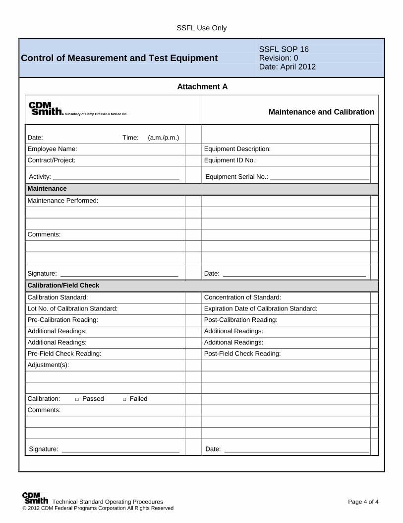
SSFL Use Only
Technical Standard Operating Procedures Page 4 of 4 © 2012 CDM Federal Programs Corporation All Rights Reserved
Control of Measurement and Test Equipment SSFL SOP 16 Revision: 0 Date: April 2012
Attachment A
A subsidiary of Camp Dresser & McKee Inc.
Maintenance and Calibration
Date: Time: (a.m./p.m.)
Employee Name: Equipment Description:
Contract/Project: Equipment ID No.:
Activity: Equipment Serial No.:
Maintenance
Maintenance Performed:
Comments:
Signature: Date:
Calibration/Field Check
Calibration Standard: Concentration of Standard:
Lot No. of Calibration Standard: Expiration Date of Calibration Standard:
Pre-Calibration Reading: Post-Calibration Reading:
Additional Readings: Additional Readings:
Additional Readings: Additional Readings:
Pre-Field Check Reading: Post-Field Check Reading:
Adjustment(s):
Calibration: □ Passed □ Failed
Comments:
Signature: Date:
SSFL Use Only
Technical Standard Operating Procedures Page 1 of 3 © 2012CDM Federal Programs Corporation All Rights Reserved
Laboratory Homogenization For Phase 3 Soil Samples
SSFL SOP 17 Revision: 0 Date: April 2012
Prepared: T. Burgesser Technical Review: C. Werden
QA Review: K. Zilis Approved and Issued:
4/6/2012
Signature/Date
1.0 Objective The objective of this standard operating procedure (SOP) is to define the requirements and responsibilities for homogenizing multiple sample containers into one discrete surface or subsurface soil for all non-volatile/semi-volatile analyses (and select other) analyses for samples collected from the Santa Susana Field Laboratory (SSFL) site. Physical homogenization of soil material will be performed by subcontract laboratories. Homogenization of the depth-discrete samples by CDM Smith will not be performed in the field or in the field trailer. This SOP is intended to identify the minimum requirements required of the subcontract laboratories and is not intended to replace or supersede existing laboratory specific SOP. 2.0 Background Soil sample homogenization prior to laboratory analysis has been requested by the California Department of Toxic Substances Control (DTSC) for the SSFL Phase 3 non-volatile chemical analyses. Homogenization was previously performed for selected SSFL Chemical Soil Background Study samples collected in the summer and fall 2011. During the background study, DTSC homogenized soil samples for chemical analyses for semi-volatile organic compounds (SVOCs), dioxins, pesticides/herbicides, and metals, not including hexavalent chromium. The DTSC has determined that homogenizing future soil samples for all inorganic and non-volatile analyses (refer to the Field Sampling Plan [FSP] Addendum) will provide greater consistency and comparability of the analytical results from future studies throughout SSFL sampling programs. During Phase 3 sampling, surface and subsurface soil samples will be collected following SSFL SOPs 2, 3, 4, and 5 through the use of stainless steel sleeves or placement in glass sample jars. Because of the volume needed for multiple chemical analyses, multiple sleeves or glass jars may be required from each sampling location. Soil samples to be analyzed for metals (not including hexavalent chromium), PCBs, dioxins/furans, pesticides, herbicides, SVOCs, and perchlorate will be subject to homogenization. Soil samples for VOC, TPH, alcohols, glycols, and similar volatiles analyses will not be homogenized. Homogenization of soil samples will be requested to be performed by each laboratory before analytical testing begins. 2.1 Definitions Grab Sample - A discrete portion of sample material or an aliquot taken from a specific sample location at a given point in time. Spoon/Scoop/Trowel - A small stainless steel, Teflon®, Teflon® -lined, or plastic utensil measuring approximately 6 inches in length with a stem-like handle (for manual operation). Samples are handled and combined collected using a scooping action. Stainless Steel or Glass Trays, Bowls or Pans – Appropriately-sized mixing containers used in the homogenization process. mall 2.2 Associated Procedures SSFL SOP 2, Surface Soil Sampling SSFL SOP 3, Subsurface Soil Sampling with Hand Auger SSFL SOP 4, Direct Push Technology Sampling SSFL SOP 5, Backhoe Trenching/Test Pits for Sample Collection SSFL SOP 10, Sample Custody
SSFL Use Only
Technical Standard Operating Procedures Page 2 of 3 © 2012CDM Federal Programs Corporation All Rights Reserved
Laboratory Homogenization For Phase 3 Soil Samples
SSFL SOP 17 Revision: 0 Date: April 2012
SSFL SOP 11, Packaging and Shipping Environmental Samples SSFL SOP 12, Field Equipment Decontamination
3.0 General Responsibilities Field Team Leader-The field team leader (FTL) is responsible for ensuring that the Field Sample Coordinator is properly trained to manage the Phase 3 samples – identifying those sample sleeves and jars that do not require homogenization and those sample sleeves and jars that do require homogenization by the subcontract laboratory. The FTL also need to confirm that the sampling team is collecting sufficient sample volume for the homogenization measures. Field Sample Coordinator–The sample coordinator is responsible for ensuring that all contracted laboratories follow this guidance in accordance with this procedure. In addition, all subcontract laboratories are required to have an SOP in place that describes in detail the specific laboratory procedures utilized to comply with this SOP. Field Sampling Team-The field sampling team is responsible for collecting the proper volume of sample (refer to Table 1 in the FSP Addendum). Laboratory Project Manager (PM)–The laboratory project manager is responsible for ensuring that all instructions regarding soil sample homogenization are followed by laboratory staff. 4.0 Required Equipment Because homogenization of samples will occur a the subcontract laboratory, the laboratory supplies at a minimum should include: Laboratory logbook, bench sheet forms, other forms for documenting sample homogenization Indelible black or blue ink pens and markers Appropriate size sample containers (glass and plastic) with labels Stainless steel or glass trays, bowls, or pans Stainless steel or Teflon lined scoops/spoons/trowels Decontamination supplies Nitrile or appropriate gloves 5.0 Procedures 5.1 Laboratory Soil Homogenization/Compositing (Cone and Quarter Method) The following steps will be performed by the analytical laboratory to create a composite soil sample for the non-volatile analyses. The laboratory will use sample quantities submitted in stainless steel sleeves or glass jars to perform this procedure. 1. Decontaminate all laboratory compositing equipment according to appropriate Laboratory SOPs.
2. Don appropriate PPE and gloves. Clean gloves must be worn for each sample composited.
3. With the top 1/3 and bottom 1/3 of sample material in the homogenization tray/bowl/pan, chop-up the sample into small
chunks using a clean, stainless steel wallboard knife or other suitable implement.
4. Remove non-soil debris, including sticks and vegetation, as much as possible.
5. Scooping from the edge, form a mound in the center of the tray/bowl/pan.
6. Divide the mound into two equal piles and form each pile into a mound.
7. Divide each into two piles. (At this point there should be four piles in the tray/bowl/pan).
8. Mix the piles together that are opposite from each other into a single mound.

SSFL Use Only
Technical Standard Operating Procedures Page 3 of 3 © 2012CDM Federal Programs Corporation All Rights Reserved
Laboratory Homogenization For Phase 3 Soil Samples
SSFL SOP 17 Revision: 0 Date: April 2012
9. Repeat steps 7, 8 and 9 until the sample is thoroughly homogenized (a minimum of 3 times).
10. Transfer the thoroughly mixed sample to appropriately labeled sample containers for the required analyses.
11. Analyze the samples. 5.2 Contracted Laboratory Compositing Equipment Decontamination To clean laboratory equipment used in homogenization, remove all gross materials/stains/hardened material using a scrubbing pad or brush and rinsing the equipment with water. After scrubbing and rinsing, the laboratory should implement internal laboratory procedures/SOPs to complete cleaning and decontamination process to ensure the compositing equipment is free of potential cross contamination. At a minimum, the laboratory decontamination process must comply with the requirements of SSFL SOP 12. 6.0 Documentation Document all compositing activities including decontamination in an appropriate logbook and/or bench sheet. 7.0 References Lancaster Laboratories Inc. 2011SOP-SS-009 Homogenization and Subsampling of Solid Waste Samples from Environmental Sources. July. State of California Department of Toxic Substances Control (DTSC), 2012. Homogenization of Soil Samples for Chemical Characterization, Santa Susana Field Laboratory, Ventura County, California. February 29, 2012.
SSFL Use Only
Technical Standard Operating Procedures Page 1 of 4 © 2012CDM Federal Programs Corporation All Rights Reserved
Clean Sampling Method for Methyl Mercury and Organotin Analyses
SSFL SOP 18 Revision: 0 Date: April 2012
Prepared: T. Burgesser Technical Review: C. Werden
QA Review: J. Oxford Approved and Issued:
4/6/2012
Signature/Date
1.0 Objective The purpose of this technical standard operating procedure (SOP) is to define the techniques and requirements for collecting sediment samples for methyl mercury and organotins analyses at the Santa Susana Field Laboratory (SSFL) site. This SOP addresses sample collection and handling techniques, but specific sample collection tools; sample collection equipment will be addressed in subsequent field sampling plan (FSP) addenda, as there may be a variety of conditions under which sediment samples are to be collected (e.g., submerged, not submerged). Attached to this SOP is EPA method 1669 which describes the sampling of ambient water for trace metals. The “clean hands” and “dirty hands” technique for collection of water samples as described in EPA Method 1669 has been adapted for the collection of sediments to minimize to the maximum extent possible cross-contamination of the sample media. The use of laboratory pre-cleaned equipment (e.g., trowels) and sample bottles is required. 2.0 Background 2.1 Definitions Grab Sample - A discrete portion of sample material or an aliquot taken from a specific sample location at a given point in time. Trowel - A small Teflon®, Teflon® -lined, or plastic disposable utensil measuring approximately 6 inches in length with a stem-like handle (for manual operation). Samples are handled and combined collected using a scooping action. 2.2 Associated Procedures SSFL SOP 1, Procedures for Locating and Clearing Phase 3 Samples SSFL SOP 2, Surface Soil Sampling SSFL SOP 6, Field Measurement of Total Organic Vapors SSFL SOP 7, Field Measurement of Residual Radiation SSFL SOP 8, Field Data Collection Documents, Content, and Control SSFL SOP 9, Lithologic Logging SSFL SOP 10, Sample Custody SSFL SOP 11, Packaging and Shipping Environmental Samples SSFL SOP 12, Field Equipment Decontamination SSFL SOP 13, Guide to Handling Investigation Derived Waste SSFL SOP 15, Photographic Documentation of Field Activities SSFL SOP 16, Control of Measurement and Test Equipment
2.3 Discussion Sediment samples are being collected and analyzed to determine the type(s) and level(s) of methyl mercury and organotin impacts in sediment. All SOPs will be on hand with the field sampling team. 3.0 General Responsibilities Field Team Leader - The field team leader (FTL) is responsible for ensuring that field personnel collect and handle sediment samples in accordance with this SOP. Site Geologist – The person responsible for collecting and logging the sediment lithology.
SSFL Use Only
Technical Standard Operating Procedures Page 2 of 4 © 2012CDM Federal Programs Corporation All Rights Reserved
Clean Sampling Method for Methyl Mercury and Organotin Analyses
SSFL SOP 18 Revision: 0 Date: April 2012
Site Health and Safety Technician– The person who will use field screening instruments to monitor all field activities for VOCs and radiological contaminants and pre-shipment sample coolers. This person is a trained radiological technician who works under the guidance of Science Application International Corporation’s (SAIC’s) Certified Health Physicist (CHP). 4.0 Required Equipment Site-specific plans (including Field Sampling Plan [FSP]
Addendum and health and safety plan) Monitoring/screening instruments required by health and
safety plan Insulated cooler Nitrile (non-talc) gloves Plastic zip-top bags Field logbook Personal protective clothing and equipment Indelible blue or black ink pen and/or marker Clear, waterproof tape Decontamination supplies Bags of ice Paper towels or Kim wipes Plastic sheeting Custody seals Appropriate sample containers (provided by the
subcontract laboratory) Disposable plastic trowels (provided by the subcontract
laboratory) Global Positioning System (GPS) unit Sample labels Trash Bags Field Sampling Data Sheets Boring and Sample Description Logs Rubber Boots
Teflon squares and sleeve end caps Chain of custody forms 2-way radios
5.0 Procedures 5.1 Preparation The following steps must be followed when preparing for sample collection: 1. Review site-specific health and safety plan and project plans (FSP Addendum) before initiating sampling activity. 2. Review EPA Method 1669 (attached) for the proper sampling procedures. 3. Designate the “clean hands” and “dirty hands” sample personnel. The sampler designated the “clean hands” person is
responsible for all operations involving contact with sample bottle and transfer of the sample from the sample collection device to the sample bottle. The “dirty hands” sampler is responsible for preparation of the sampler (except the sample containers itself) operation of machinery, and all other activities that does not involve direct contact with the sample.
4. Don the appropriate personal protective clothing as specified in the site-specific health and safety plan. Clean non-talc
gloves must be worn at all times when handling sampling equipment and containers 5. Locate sampling location(s) in accordance with FSP Addendum and document pertinent information in the field
logbook (SSFL SOP 8). Confirm GPS coordinates of each location (SSFL SOP 1). 6. Use clean (decontaminated) sampling tools that have been provided by the subcontract laboratory to obtain sample
material from each specified sample location. 7. Carefully remove stones, vegetation, debris, etc. from the sediment surface (below water level) in the sampling location
area, if possible. Clear the sample location using a new and/or appropriately decontaminated tool (trowel/scoop provided by the subcontract laboratory) as described to expose a fresh sampling surface. Whenever possible stand downstream of the sample location to minimize introduction of contamination and to minimize disturbing the sediment to be sampled. Sediment deposits that have been disturbed in any manner (e.g., splashed, walked-on, or agitated) by field personnel should not be sampled.

SSFL Use Only
Technical Standard Operating Procedures Page 3 of 4 © 2012CDM Federal Programs Corporation All Rights Reserved
Clean Sampling Method for Methyl Mercury and Organotin Analyses
SSFL SOP 18 Revision: 0 Date: April 2012
8. The Site Health and Safety Technician will perform contaminant screening using hand-held instruments at each sample location before sampling and for each sample collected (SSFL SOPs 6 and 7). The most recent spoils materials will be segregated to minimize cross-contamination. The breathing zone and excavated materials will be monitored continuously. If levels are detected above health and safety plan action levels (HASP page 8), work will be temporarily discontinued. If radiation levels, exceed two times (2X) background levels (HASP page 8), the Department of Energy (DOE), The Boeing Company (Boeing), and the California Department of Toxic Substances Control (DTSC) will be contacted. Site work will not resume at that location until further guidance is provided by DOE or Boeing. Contact information is in the health and safety plan.
5.2 Sample Collection Because of the potential variety of conditions (i.e., not submerged. partially submerged, and submerged) under which sediment samples may be collected, the specific sample collection equipment has not been designated herein. However, regardless of the equipment used to obtain the sample material, for example, scoops, dredges, cores, the post-collection handling will be the same. The following general steps must be followed when collecting sediment samples for methyl mercury and organotins analyses. 1. Wear new, clean, non-talc gloves during handling of all sample containers and sampling devices. Change out gloves at
each sampling location, or each time a new sample is to be collected to avoid cross-contamination. 2. Document the sampling process by recording the location, hydraulic condition, sampling equipment, and depth in the
designated field logbook. 3. The “dirty hands” person collects the sample using the designated, decontaminated sampling equipment. Describe and
log the sediment using the Unified Soil Classification System (USCS; SSFL SOP 9) on boring logs and a field sampling data sheet (FSDS). Document any and all deviations from the SOPs and the FSP Addendum in the field logbook and include rationale for changes (SSFL SOP 8).
4. The Site health and safety technician screens the exterior of the sampler for the presence of VOC and radiological
contaminants (SSFL SOPs 6 and 7), and documents measured concentrations. 5. The “clean hands” person uses a clean, non-metallic trowel/scoop (provided by the subcontract laboratory) to scoop
sample from the designated sample depth and transfer the material to the appropriate sample bottles. Several scoops may be required from this interval to collect the amount of sediment required to satisfy the analytical protocol (refer to Table 1 in the FSP Addendum). Minimize the inclusion of any pore water into the sample bottle by carefully decanting the water from the trowel before transfer to the sample bottle. Quickly cap the sample bottle.
6. Fill out the sample label with the appropriate sample information (e.g., sample identification, date/time of sample
collection, requested analyses) per FSP Addendum Table 1. Attach the label to the sample bottle that has been externally cleaned using a paper towel or Kimwipe.
7. Place sample containers in individual zip-top plastic bags (provided by the subcontract laboratory) and seal the bags.
Place baggies onto ice in an insulated cooler (provided by the subcontract laboratory) to maintain at 4°C (±2°C). 8. Because all sampling equipment used for the collection of methyl mercury and organotin samples is disposable,
decontamination of the equipment is not required and contaminated equipment should be handled per SSFL SOP 13. 9. Any excess sediments material should be discarded back in the hole and no sediment IDW is expected.
5.2.1 Collection of Field Blanks To demonstrate that sample contamination has not occurred from ambient air during sampling and sample handling, one field blank will be generated for every 10 collected samples. The water used for field blanks is certified clean and provided by the subcontract laboratory and transported to the sampling location.

SSFL Use Only
Technical Standard Operating Procedures Page 4 of 4 © 2012CDM Federal Programs Corporation All Rights Reserved
Clean Sampling Method for Methyl Mercury and Organotin Analyses
SSFL SOP 18 Revision: 0 Date: April 2012
1. Transfer the required volume of field blank water to the appropriate pre-cleaned sample container (provided by the subcontract laboratory).
2. Fill out the sample label with the appropriate sample information (e.g., sample identification, date/time of sample
collection, requested analyses) per FSP Addendum Table 1 and attach to sample bottle. 3. Place sample containers in individual zip-top plastic bags (provided by the contracted laboratory) and seal the bags.
Place the bagged samples on ice in an insulated cooler (provided by the subcontract laboratory) to maintain at 4°C (±2°C).
5.2.2 Sample Packing and Shipment 1. Store samples at 4°C (±2°C) until samples are delivered to the designated analytical laboratory. 2. Pack all samples per SSFL SOP 11 and/or laboratory requirements. Include properly completed documentation and affix
signed and dated custody seals to the cooler lid. See SSFL SOP 10 for guidance on sample custody procedures.
6.0 Restrictions/Limitations The method requires “clean hands” and “dirty hands” sample personnel to properly implement this technique. All sampling equipment (e.g., scoops/trowels, sample jars, field blank water, sample coolers) must come from the subcontract laboratory. The two exceptions to subcontract laboratory-provided equipment are the specific sampling tool used to collect the media (unless the laboratory scoop is appropriate) and the ice used to preserve the samples. In addition, the specific sampling tool to collect the sediment samples must be described in the FSP Addendum. 7.0 References United States Environmental Protection Agency. Method 1669 Sampling Ambient Water for Trace Metals at EPA Water Quality Criteria Levels. July 1996. 8.0 Attachments Attachment A – Method 1669 – Sampling Ambient Water for Trace Metals at EPA Water Quality Criteria Levels

Method 1669
Sampling Ambient Water for Trace Metals at EPA Water QualityCriteria Levels
July 1996
U.S. Environmental Protection AgencyOffice of Water
Engineering and Analysis Division (4303)401 M Street S.W.
Washington, D.C. 20460
Method 1669
ii July 1996
Acknowledgements
This sampling method was prepared under the direction of William A. Telliard of the Engineeringand Analysis Division (EAD) within the U.S. Environmental Agency's (EPA's) Office of Scienceand Technology (OST). This sampling method was prepared under EPA Contract 68-C3-0337by the DynCorp Environmental Programs Division, with assistance from Interface, Inc.
The following researchers contributed to the philosophy behind this sampling method. Theircontribution is gratefully acknowledged:
Shier Berman, National Research Council, Ottawa, Ontario, Canada;Nicholas Bloom, Frontier Geosciences Inc, Seattle, Washington;Eric Crecelius, Battelle Marine Sciences Laboratory, Sequim, Washington;Russell Flegal, University of California/Santa Cruz, California;Gary Gill, Texas A&M University at Galveston, Texas;Carlton Hunt and Dion Lewis, Battelle Ocean Sciences, Duxbury, Massachusetts;Carl Watras, Wisconsin Department of Natural Resources, Boulder Junction, Wisconsin
Additional support was provided by Ted Martin of the EPA Office of Research andDevelopment's Environmental Monitoring Systems Laboratory in Cincinnati, Ohio and by ArthurHorowitz of the U.S. Geological Survey.
This version of the method was prepared after observations of sampling teams from the Universityof California at Santa Cruz, the Wisconsin Department of Natural Resources, the U.S. GeologicalSurvey, and Battelle Ocean Sciences. The assistance of personnel demonstrating the samplingtechniques used by these institutions is gratefully acknowledged.
Disclaimer
This sampling method has been reviewed and approved for publication by the Analytical MethodsStaff within the Engineering and Analysis Division of the U.S. Environmental Protection Agency.Mention of trade names or commercial products does not constitute endorsement orrecommendation for use.
Further Information
For further information, contact:
W.A. TelliardEngineering and Analysis Division (4303)U.S. Environmental Protection Agency401 M Street, SWWashington, DC 20460Phone: 202/260–7134Fax: 202/260–7185
Method 1669
July 1996 iii
Introduction
This sampling method was designed to support water quality monitoring programs authorizedunder the Clean Water Act. Section 304(a) of the Clean Water Act requires EPA to publish waterquality criteria that reflect the latest scientific knowledge concerning the physical fate (e.g.,concentration and dispersal) of pollutants, the effects of pollutants on ecological and humanhealth, and the effect of pollutants on biological community diversity, productivity, and stability.
Section 303 of the Clean Water Act requires states to set a water quality standard for each bodyof water within its boundaries. A state water quality standard consists of a designated use or usesof a waterbody or a segment of a waterbody, the water quality criteria that are necessary to protectthe designated use or uses, and an antidegradation policy. These water quality standards serve twopurposes: (1) they establish the water quality goals for a specific waterbody, and (2) they are thebasis for establishing water quality-based treatment controls and strategies beyond the technology-based controls required by Sections 301(b) and 306 of the Clean Water Act.
In defining water quality standards, the state may use narrative criteria, numeric criteria, or both.However, the 1987 amendments to the Clean Water Act required states to adopt numeric criteriafor toxic pollutants (designated in Section 307(a) of the Act) based on EPA Section 304(a) criteriaor other scientific data, when the discharge or presence of those toxic pollutants could reasonablybe expected to interfere with designated uses.
In some cases, these water quality criteria are as much as 280 times lower than those achievableusing existing EPA methods and required to support technology-based permits. Therefore, thissampling method, and the analytical methods referenced in Table 1 of this document, weredeveloped by EPA to specifically address state needs for measuring toxic metals at water qualitycriteria levels, when such measurements are necessary to protect designated uses in state waterquality standards. The latest criteria published by EPA are those listed in the National Toxics Rule(57 FR 60848) and the Stay of Federal Water Quality Criteria for Metals (60 FR 22228). Theserules include water quality criteria for 13 metals, and it is these criteria on which this samplingmethod and the referenced analytical methods are based.
In developing these methods, EPA found that one of the greatest difficulties in measuringpollutants at these levels was precluding sample contamination during collection, transport, andanalysis. The degree of difficulty, however, is highly dependent on the metal and site-specificconditions. This method, therefore, is designed to provide the level of protection necessary topreclude contamination in nearly all situations. It is also designed to provide the proceduresnecessary to produce reliable results at the lowest possible water quality criteria published by EPA.In recognition of the variety of situations to which this method may be applied, and in recognitionof continuing technological advances, the method is performance-based. Alternative proceduresmay be used, so long as those procedures are demonstrated to yield reliable results.
Requests for additional copies of this method should be directed to:
U.S. EPA NCEPI11029 Kenwood RoadCincinnati, OH 45242513/489–8190
Method 1669
iv July 1996
Note: This document is intended as guidance only. Use of the terms "must," "may,"and "should" are included to mean that EPA believes that these procedures must, may,or should be followed in order to produce the desired results when using this guidance. In addition, the guidance is intended to be performance-based, in that the use of lessstringent procedures may be used so long as neither samples nor blanks arecontaminated when following those modified procedures. Because the only way tomeasure the performance of the modified procedures is through the collection andanalysis of uncontaminated blank samples in accordance with this guidance and thereferenced methods, it is highly recommended that any modifications be thoroughlyevaluated and demonstrated to be effective before field samples are collected.
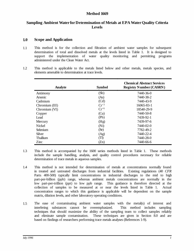
July 1996 1
Method 1669
Sampling Ambient Water for Determination of Metals at EPA Water Quality CriteriaLevels
1.0 Scope and Application
1.1 This method is for the collection and filtration of ambient water samples for subsequentdetermination of total and dissolved metals at the levels listed in Table 1. It is designed tosupport the implementation of water quality monitoring and permitting programsadministered under the Clean Water Act.
1.2 This method is applicable to the metals listed below and other metals, metals species, andelements amenable to determination at trace levels.
Analyte SymbolChemical Abstract ServicesRegistry Number (CASRN)
Antimony (Sb) 7440-36-0Arsenic (As) 7440-38-2Cadmium (Cd) 7440-43-9Chromium (III) Cr+3 16065-83-1Chromium (VI) Cr+6 18540-29-9Copper (Cu) 7440-50-8Lead (Pb) 7439-92-1Mercury (Hg) 7439-97-6Nickel (Ni) 7440-02-0Selenium (Se) 7782-49-2Silver (Ag) 7440-22-4Thallium (Tl) 7440-28-0Zinc (Zn) 7440-66-6
1.3 This method is accompanied by the 1600 series methods listed in Table 1. These methodsinclude the sample handling, analysis, and quality control procedures necessary for reliabledetermination of trace metals in aqueous samples.
1.4 This method is not intended for determination of metals at concentrations normally foundin treated and untreated discharges from industrial facilities. Existing regulations (40 CFRParts 400-500) typically limit concentrations in industrial discharges to the mid to highpart-per-billion (ppb) range, whereas ambient metals concentrations are normally in thelow part-per-trillion (ppt) to low ppb range. This guidance is therefore directed at thecollection of samples to be measured at or near the levels listed in Table 1. Actualconcentration ranges to which this guidance is applicable will be dependent on the samplematrix, dilution levels, and other laboratory operating conditions.
1.5 The ease of contaminating ambient water samples with the metal(s) of interest andinterfering substances cannot be overemphasized. This method includes samplingtechniques that should maximize the ability of the sampling team to collect samples reliablyand eliminate sample contamination. These techniques are given in Section 8.0 and arebased on findings of researchers performing trace metals analyses (References 1-9).
Method 1669
2 July 1996
1.6 Clean and Ultraclean—The terms "clean" and "ultraclean" have been used in other Agencyguidance to describe the techniques needed to reduce or eliminate contamination in tracemetals determinations. These terms are not used in this sampling method due to a lack ofexact definitions. However, the information provided in this method is consistent withsummary guidance on clean and ultraclean techniques (Reference 10).
1.7 This sampling method follows the EPA Environmental Methods Management Council's"Format for Method Documentation" (Reference 11).
1.8 Method 1669 is "performance-based"; i.e., an alternate sampling procedure or techniquemay be used, so long as neither samples nor blanks are contaminated when following thealternate procedures. Because the only way to measure the performance of the alternateprocedures is through the collection and analysis of uncontaminated blank samples inaccordance with this guidance and the methods referenced in Table 1, it is highlyrecommended that any modifications be thoroughly evaluated and demonstrated to beeffective before field samples are collected. Section 9.2 provides additional details on thetests and documentation required to support equivalent performance.
1.9 For dissolved metal determinations, samples must be filtered through a 0.45 µm capsulefilter at the field site. The filtering procedures are described in this method. The filteredsamples may be preserved in the field or transported to the laboratory for preservation.Procedures for field preservation are detailed in this sampling method; procedures forlaboratory preservation are provided in the methods referenced in Table 1. Preservationrequirements are summarized in Table 2.
1.10 The procedures in this method are for use only by personnel thoroughly trained in thecollection of samples for determination of metals at ambient water quality control levels.
2.0 Summary of Method
2.1 Before samples are collected, all sampling equipment and sample containers are cleanedin a laboratory or cleaning facility using detergent, mineral acids, and reagent water asdescribed in the methods referenced in Table 1. The laboratory or cleaning facility isresponsible for generating an acceptable equipment blank to demonstrate that the samplingequipment and containers are free from trace metals contamination before they are shippedto the field sampling team. An acceptable blank is one that is free from contaminationbelow the minimum level (ML) specified in the referenced analytical method (Section 9.3).
2.2 After cleaning, sample containers are filled with weak acid solution, individually double-bagged, and shipped to the sampling site. All sampling equipment is also bagged forstorage or shipment.
NOTE: EPA has found that, in some cases, it may be possible to empty the weak acid solution from the bottleimmediately prior to transport to the field site. In this case, the bottle should be refilled with reagent water (Section 7.1).
2.3 The laboratory or cleaning facility must prepare a large carboy or other appropriate cleancontainer filled with reagent water (Section 7.1) for use with collection of field blanksduring sampling activities. The reagent-water-filled container should be shipped to thefield site and handled as all other sample containers and sampling equipment. At least onefield blank should be processed per site, or one per every ten samples, whichever is morefrequent (Section 9.4). If samples are to be collected for determination of trivalent

Method 1669
July 1996 3
chromium, the sampling team processes additional QC aliquots are processed as describedin Section 9.6.
2.4 Upon arrival at the sampling site, one member of the two-person sampling team isdesignated as "dirty hands"; the second member is designated as "clean hands." Alloperations involving contact with the sample bottle and transfer of the sample from thesample collection device to the sample bottle are handled by the individual designated as"clean hands." "Dirty hands" is responsible for preparation of the sampler (except thesample container itself), operation of any machinery, and for all other activities that do notinvolve direct contact with the sample.
2.5 All sampling equipment and sample containers used for metals determinations at or nearthe levels listed in Table 1 must be nonmetallic and free from any material that may containmetals.
2.6 Sampling personnel are required to wear clean, nontalc gloves at all times when handlingsampling equipment and sample containers.
2.7 In addition to processing field blanks at each site, a field duplicate must be collected ateach sampling site, or one field duplicate per every 10 samples, whichever is more frequent(Section 9.5). Section 9.0 gives a complete description of quality control requirements.
2.8 Sampling
2.8.1 Whenever possible, samples are collected facing upstream and upwind to minimizeintroduction of contamination.
2.8.2 Samples may be collected while working from a boat or while on land.
2.8.3 Surface samples are collected using a grab sampling technique. The principle of thegrab technique is to fill a sample bottle by rapid immersion in water and cappingto minimize exposure to airborne particulate matter.
2.8.4 Subsurface samples are collected by suction of the sample into an immersed samplebottle or by pumping the sample to the surface.
2.9 Samples for dissolved metals are filtered through a 0.45 µm capsule filter at the field site.After filtering, the samples are double-bagged and iced immediately. Sample containersare shipped to the analytical laboratory. The sampling equipment is shipped to thelaboratory or cleaning facility for recleaning.
2.10 Acid preservation of samples is performed in the field or in the laboratory. Fieldpreservation is necessary for determinations of trivalent chromium. It has also been shownthat field preservation can increase sample holding times for hexavalent chromium to 30days; therefore it is recommended that preservation of samples for hexavalent chromiumbe performed in the field. For other metals, however, the sampling team may prefer toutilize laboratory preservation of samples to expedite field operations and to minimize thepotential for sample contamination.
2.11 Sampling activities must be documented through paper or computerized sample trackingsystems.
Method 1669
4 July 1996
3.0 Definitions
3.1 Apparatus—Throughout this method, the sample containers, sampling devices,instrumentation, and all other materials and devices used in sample collection, sampleprocessing, and sample analysis activities will be referred to collectively as the Apparatus.
3.2 Definitions of other terms are given in the Glossary (Section 15.0) at the end of thismethod.
4.0 Contamination and Interferences
4.1 Contamination Problems in Trace Metals Analysis
4.1.1 Preventing ambient water samples from becoming contaminated during thesampling and analytical process is the greatest challenge faced in trace metalsdeterminations. In recent years, it has been shown that much of the historical tracemetals data collected in ambient water are erroneously high because theconcentrations reflect contamination from sampling and analysis rather thanambient levels (Reference 12). Therefore, it is imperative that extreme care betaken to avoid contamination when collecting and analyzing ambient water samplesfor trace metals.
4.1.2 There are numerous routes by which samples may become contaminated. Potentialsources of trace metals contamination during sampling include metallic or metal-containing sampling equipment, containers, labware (e.g. talc gloves that containhigh levels of zinc), reagents, and deionized water; improperly cleaned and storedequipment, labware, and reagents; and atmospheric inputs such as dirt and dustfrom automobile exhaust, cigarette smoke, nearby roads, bridges, wires, and poles.Even human contact can be a source of trace metals contamination. For example,it has been demonstrated that dental work (e.g., mercury amalgam fillings) in themouths of laboratory personnel can contaminate samples that are directly exposedto exhalation (Reference 3).
4.2 Contamination Control
4.2.1 Philosophy—The philosophy behind contamination control is to ensure that anyobject or substance that contacts the sample is nonmetallic and free from anymaterial that may contain metals of concern.
4.2.1.1 The integrity of the results produced cannot be compromised bycontamination of samples. Requirements and suggestions for controllingsample contamination are given in this sampling method and in theanalytical methods referenced in Table 1.
4.2.1.2 Substances in a sample or in the surrounding environment cannot beallowed to contaminate the Apparatus used to collect samples for tracemetals measurements. Requirements and suggestions for protecting theApparatus are given in this sampling method and in the methods referencedin Table 1.
4.2.1.3 While contamination control is essential, personnel health and safety remainthe highest priority. Requirements and suggestions for personnel safety are
Method 1669
July 1996 5
given in Section 5 of this sampling method and in the methods referencedin Table 1.
4.2.2 Avoiding contamination—The best way to control contamination is to completelyavoid exposure of the sample and Apparatus to contamination in the first place.Avoiding exposure means performing operations in an area known to be free fromcontamination. Two of the most important factors in avoiding/reducing samplecontamination are (1) an awareness of potential sources of contamination and (2)strict attention to work being performed. Therefore, it is imperative that theprocedures described in this method be carried out by well trained, experiencedpersonnel. Documentation of training should be kept on file and readily availablefor review.
4.2.2.1 Minimize exposure—The Apparatus that will contact samples or blanksshould only be opened or exposed in a clean room, clean bench, glove box,or clean plastic bag, so that exposure to atmospheric inputs is minimized.When not being used, the Apparatus should be covered with clean plasticwrap, stored in the clean bench or in a plastic box or glove box, or baggedin clean, colorless zip-type bags. Minimizing the time between cleaning anduse will also reduce contamination.
4.2.2.2 Wear gloves—Sampling personnel must wear clean, nontalc gloves (Section6.7) during all operations involving handling of the Apparatus, samples, andblanks. Only clean gloves may touch the Apparatus. If another object orsubstance is touched, the glove(s) must be changed before again handlingthe Apparatus. If it is even suspected that gloves have becomecontaminated, work must be halted, the contaminated gloves removed, anda new pair of clean gloves put on. Wearing multiple layers of clean gloveswill allow the old pair to be quickly stripped with minimal disruption to thework activity.
4.2.2.3 Use metal-free Apparatus—All Apparatus used for metals determinationsat the levels listed in Table 1 must be nonmetallic and free of material thatmay contain metals. When it is not possible to obtain equipment that iscompletely free of the metal(s) of interest, the sample should not come intodirect contact with the equipment.
4.2.2.3.1 Construction materials—Only the following materialsshould come in contact with samples: fluoropolymer (FEP,PTFE), conventional or linear polyethylene, polycarbonate,polysulfone, polypropylene, or ultrapure quartz. PTFE isless desirable than FEP because the sintered material inPTFE may contain contaminants and is susceptible toserious memory effects (Reference 6). Fluoropolymer orglass containers should be used for samples that will beanalyzed for mercury because mercury vapors can diffuse inor out of other materials, resulting either in contaminationor low-biased results (Reference 3). Metal must not be usedunder any circumstance. Regardless of construction, allmaterials that will directly or indirectly contact the samplemust be cleaned using the procedures described in the
Method 1669
6 July 1996
referenced analytical methods (see Table 1) and must beknown to be clean and metal-free before proceeding.
4.2.2.3.2 The following materials have been found to contain tracemetals and must not be used to hold liquids that come incontact with the sample or must not contact the sample,unless these materials have been shown to be free of themetals of interest at the desired level: Pyrex, Kimax,methacrylate, polyvinylchloride, nylon, and Vycor(Reference 6). In addition, highly colored plastics, papercap liners, pigments used to mark increments on plastics,and rubber all contain trace levels of metals and must beavoided (Reference 13).
4.2.2.3.3 Serialization—Serial numbers should be indelibly marked oretched on each piece of Apparatus so that contaminationcan be traced, and logbooks should be maintained to trackthe sample from the container through the sampling processto shipment to the laboratory. Chain-of-custody proceduresmay also be used if warranted so that contamination can betraced to particular handling procedures or lab personnel.
4.2.2.3.4 The Apparatus should be clean when the sampling teamreceives it. If there are any indications that the Apparatus isnot clean (e.g., a ripped storage bag), an assessment of thelikelihood of contamination must be made. Sampling mustnot proceed if it is possible that the Apparatus iscontaminated. If the Apparatus is contaminated, it must bereturned to the laboratory or cleaning facility for propercleaning before any sampling activity resumes.
4.2.2.3.5 Details for recleaning the Apparatus between collection ofindividual samples are provided in Section 10.0.
4.2.2.4 Avoid sources of contamination—Avoid contamination by being aware ofpotential sources and routes of contamination.
4.2.2.4.1 Contamination by carryover—Contamination may occurwhen a sample containing low concentrations of metals isprocessed immediately after a sample containing relativelyhigh concentrations of these metals. At sites where morethan one sample will be collected, the sample known orexpected to contain the lowest concentration of metalsshould be collected first with the sample containing thehighest levels collected last (Section 8.1.4). This will helpminimize carryover of metals from high- concentrationsamples to low- concentration samples. If the samplingteam does not have prior knowledge of the waterbody, orwhen necessary, the sample collection system should berinsed with dilute acid and reagent water between samplesand followed by collection of a field blank (Section 10.3).
Method 1669
July 1996 7
4.2.2.4.2 Contamination by samples—Significant contamination ofthe Apparatus may result when untreated effluents, in-process waters, landfill leachates, and other samplescontaining mid- to high-level concentrations of inorganicsubstances are processed. As stated in Section 1.0, thissampling method is not intended for application to thesesamples, and samples containing high concentrations ofmetals must not be collected, processed, or shipped at thesame time as samples being collected for trace metalsdeterminations.
4.2.2.4.3 Contamination by indirect contact—Apparatus that may notdirectly contact samples may still be a source ofcontamination. For example, clean tubing placed in a dirtyplastic bag may pick up contamination from the bag andsubsequently transfer the contamination to the sample.Therefore, it is imperative that every piece of the Apparatusthat is directly or indirectly used in the collection of ambientwater samples be cleaned as specified in the analyticalmethod(s) referenced in Table 1.
4.2.2.4.4 Contamination by airborne particulate matter—Lessobvious substances capable of contaminating samplesinclude airborne particles. Samples may be contaminated byairborne dust, dirt, particulate matter, or vapors fromautomobile exhaust; cigarette smoke; nearby corroded orrusted bridges, pipes, poles, or wires; nearby roads; andeven human breath (Section 4.1.2). Whenever possible, thesampling activity should occur as far as possible fromsources of airborne contamination (Section 8.1.3). Areaswhere nearby soil is bare and subject to wind erosion shouldbe avoided.
4.3 Interferences—Interferences resulting from samples will vary considerably from source tosource, depending on the diversity of the site being sampled. If a sample is suspected ofcontaining substances that may interfere in the determination of trace metals, sufficientsample should be collected to allow the laboratory to identify and overcome interferenceproblems.
5.0 Safety
5.1 The toxicity or carcinogenicity of the chemicals used in this method has not been preciselydetermined; however, these chemicals should be treated as a potential health hazard.Exposure should be reduced to the lowest possible level. Sampling teams are responsiblefor maintaining a current awareness file of OSHA regulations for the safe handling of thechemicals specified in this method. A reference file of Material Safety Data Sheets shouldalso be made available to all personnel involved in sampling. It is also suggested that theorganization responsible perform personal hygiene monitoring of each sampling teammember who uses this method and that the results of this monitoring be made availableto the member.
Method 1669
8 July 1996
5.2 Operating in and around waterbodies carries the inherent risk of drowning. Life jacketsmust be worn when operating from a boat, when sampling in more than a few feet ofwater, or when sampling in swift currents.
5.3 Collecting samples in cold weather, especially around cold water bodies, carries the riskof hypothermia, and collecting samples in extremely hot and humid weather carries the riskof dehydration and heat stroke. Sampling team members should wear adequate clothingfor protection in cold weather and should carry an adequate supply of water or otherliquids for protection against dehydration in hot weather.
6.0 Apparatus and Materials
NOTE: Brand names, suppliers, and part numbers are for illustration only and no endorsement is implied. Equivalentperformance may be achieved using apparatus and materials other than those specified here. Meeting the performance requirementsof this method is the responsibility of the sampling team and laboratory.
6.1 All sampling equipment and sample containers must be precleaned in a laboratory orcleaning facility, as described in the methods referenced in Table 1, before they are shippedto the field site. Performance criteria for equipment cleaning is described in the referencedmethods. To minimize difficulties in sampling, the equipment should be packaged andarranged to minimize field preparation.
6.2 Materials such as gloves (Section 6.7), storage bags (Section 6.8), and plastic wrap (Section6.9), may be used new without additional cleaning unless the results of the equipment blankpinpoint any of these materials as a source of contamination. In this case, either a differentsupplier must be obtained or the materials must be cleaned.
6.3 Sample Bottles—Fluoropolymer (FEP, PTFE), conventional or linear polyethylene,polycarbonate, or polypropylene; 500 mL or 1 L with lids. If mercury is a target analyte,fluoropolymer or glass bottles should be used. Refer to the methods referenced in Table1 for bottle cleaning procedures.
6.3.1 Cleaned sample bottles should be filled with 0.1% HCl (v/v). In some cases, it maybe possible to empty the weak acid solution from the sample bottle immediatelyprior to transport to the field site. In this case, the bottle should be refilled withreagent water (Section 7.1).
6.3.2 Whenever possible, sampling devices should be cleaned and prepared for field usein a class 100 clean room. Preparation of the devices in the field should be donewithin the glove bag (Section 6.6). Regardless of design, sampling devices must beconstructed of nonmetallic material (Section 4.2.2.3.1) and free from material thatcontains metals. Fluoropolymer or other material shown not to adsorb orcontribute mercury must be used if mercury is a target analyte; otherwise,polyethylene, polycarbonate, or polypropylene are acceptable. Commerciallyavailable sampling devices may be used provided that any metallic or metal-containing parts are replaced with parts constructed of nonmetallic material.
6.4 Surface Sampling Devices—Surface samples are collected using a grab sampling technique.Samples may be collected manually by direct submersion of the bottle into the water or byusing a grab sampling device. Examples of grab samplers are shown in Figures 1 and 2and may be used at sites where depth profiling is neither practical nor necessary.
Method 1669
July 1996 9
6.4.1 The grab sampler in Figure 1 consists of a heavy fluoropolymer collar fastened tothe end of a 2-m-long polyethylene pole, which serves to remove the samplingpersonnel from the immediate vicinity of the sampling point. The collar holds thesample bottle. A fluoropolymer closing mechanism, threaded onto the bottle,enables the sampler to open and close the bottle under water, thereby avoidingsurface microlayer contamination (Reference 14). Polyethylene, polycarbonate, andpolypropylene are also acceptable construction materials unless mercury is a targetanalyte. Assembly of the cleaned sampling device is as follows (refer to Figure 1):
6.4.1.1 Thread the pull cord (with the closing mechanism attached) through theguides and secure the pull ring with a simple knot. Screw a sample bottleonto the closing device and insert the bottle into the collar. Cock theclosing plate so that the plate is pushed away from the operator.
6.4.1.2 The cleaned and assembled sampling device should be stored in a doublelayer of large, clean zip-type polyethylene bags or wrapped in two layers ofclean polyethylene wrap if it will not be used immediately.
6.4.2 An alternate grab sampler design is shown in Figure 2. This grab sampler is usedfor discrete water samples and is constructed so that a capped clean bottle can besubmerged, the cap removed, sample collected, and bottle recapped at a selecteddepth. This device eliminates sample contact with conventional samplers (e.g.,Niskin bottles), thereby reducing the risk of extraneous contamination. Because afresh bottle is used for each sample, carryover from previous samples is eliminated(Reference 15).
6.5 Subsurface Sampling Devices—Subsurface sample collection may be appropriate in lakesand sluggish deep river environments or where depth profiling is determined to benecessary. Subsurface samples are collected by pumping the sample into a sample bottle.Examples of subsurface collection systems include the jar system device shown in Figure3 and described in Section 6.5.1 or the continuous-flow apparatus shown in Figure 4 anddescribed in Section 6.5.2.
6.5.1 Jar sampler (Reference 14)—The jar sampler (Figure 3) is comprised of a heavyfluoropolymer 1-L jar with a fluoropolymer lid equipped with two 1/4 in.fluoropolymer fittings. Sample enters the jar through a short length offluoropolymer tubing inserted into one fitting. Sample is pulled into the jar bypumping on fluoropolymer tubing attached to the other fitting. A thickfluoropolymer plate supports the jar and provides attachment points for afluoropolymer safety line and fluoropolymer torpedo counterweight.
6.5.1.1 Advantages of the jar sampler for depth sampling are (1) all wetted surfacesare fluoropolymer and can be rigorously cleaned; (2) the sample is collectedinto a sample jar from which the sample is readily recovered, and the jar canbe easily recleaned; (3) the suction device (a peristaltic or rotary vacuumpump, Section 6.15) is located in the boat, isolated from the sampling jar;(4) the sampling jar can be continuously flushed with sample, at samplingdepth, to equilibrate the system; and (5) the sample does not travel throughlong lengths of tubing that are more difficult to clean and keep clean(Reference 14). In addition, the device is designed to eliminate atmosphericcontact with the sample during collection.
Method 1669
10 July 1996
6.5.1.2 To assemble the cleaned jar sampler, screw the torpedo weight onto themachined bolt attached to the support plate of the jar sampler. Attach asection of the 1/4 in. o.d. tubing to the jar by inserting the tubing into thefitting on the lid and pushing down into the jar until approximately 8 cmfrom the bottom. Tighten the fitting nut securely. Attach the solid safetyline to the jar sampler using a bowline knot to the loop affixed to thesupport plate.
6.5.1.3 For the tubing connecting the pump to the sampler, tubing lengths of up to12 m have been used successfully (Reference 14).
6.5.2 Continuous-flow sampler (References 16-17)—This sampling system, shown inFigure 4, consists of a peristaltic or submersible pump and one or more lengths ofprecleaned fluoropolymer or styrene/ethylene/butylene/ silicone (SEBS) tubing.A filter is added to the sampling train when sampling for dissolved metals.
6.5.2.1 Advantages of this sampling system include (1) all wetted surfaces arefluoropolymer or SEBS and can be readily cleaned; (2) the suction deviceis located in the boat, isolated from the sample bottle; (3) the sample doesnot travel through long lengths of tubing that are difficult to clean and keepclean; and (4) in-line filtration is possible, minimizing field handlingrequirements for dissolved metals samples.
6.5.2.2 The sampling team assembles the system in the field as described in Section8.2.8. System components include an optional polyethylene pole to removesampling personnel from the immediate vicinity of the sampling point andthe pump, tubing, filter, and filter holder listed in Sections 6.14 and 6.15.
6.6 Field-Portable Glove Bag—I2R, Model R-37-37H (nontalc), or equivalent. Alternately,a portable glove box may be constructed with a nonmetallic (PVC pipe or other suitablematerial) frame and a frame cover made of an inexpensive, disposable, nonmetallicmaterial (e.g., a thin-walled polyethylene bag) (Reference 7).
6.7 Gloves—Clean, nontalc polyethylene, latex, vinyl, or PVC; various lengths. Shoulder-length gloves are needed if samples are to be collected by direct submersion of the samplebottle into the water or when sampling for mercury.
6.7.1 Gloves, shoulder-length polyethylene—Associated Bag Co., Milwaukee, WI, 66-3-301, or equivalent.
6.7.2 Gloves, PVC—Fisher Scientific Part No. 11-394-100B, or equivalent.
6.8 Storage Bags—Clean, zip-type, nonvented, colorless polyethylene (various sizes).
6.9 Plastic Wrap—Clean, colorless polyethylene.
6.10 Cooler—Clean, nonmetallic, with white interior for shipping samples.
6.11 Ice or Chemical Refrigerant Packs—To keep samples chilled in the cooler duringshipment.
6.12 Wind Suit—Pamida, or equivalent.
Method 1669
July 1996 11
NOTE: This equipment is necessary only for collection of metals, such as mercury, that are known to have elevated atmosphericconcentrations.
6.12.1 An unlined, long-sleeved wind suit consisting of pants and jacket and constructedof nylon or other synthetic fiber is worn when sampling for mercury to preventmercury adsorbed onto cotton or other clothing materials from contaminatingsamples.
6.12.2 Washing and drying—The wind suit is washed by itself or with other wind suits onlyin a home or commercial washing machine and dried in a clothes dryer. Theclothes dryer must be thoroughly vacuumed, including the lint filter, to remove alltraces of lint before drying. After drying, the wind suit is folded and stored in aclean polyethylene bag for shipment to the sample site.
6.13 Boat
6.13.1 For most situations (e.g., most metals under most conditions), the use of anexisting, available boat is acceptable. A flat-bottom, Boston Whaler-type boat ispreferred because sampling materials can be stored with reduced chance of tipping.
6.13.1.1 Immediately before use, the boat should be washed with water fromthe sampling site away from any sampling points to remove any dustor dirt accumulation.
6.13.1.2 Samples should be collected upstream of boat movement.
6.13.2 For mercury, and for situations in which the presence of contaminants cannototherwise be controlled below detectable levels, the following equipment andprecautions may be necessary:
6.13.2.1 A metal-free (e.g., fiberglass) boat, along with wooden or fiberglassoars. Gasoline- or diesel-fueled boat motors should be avoidedwhen possible because the exhaust can be a source ofcontamination. If the body of water is large enough to require useof a boat motor, the engine should be shut off at a distance farenough from the sampling point to avoid contamination, and thesampling team should manually propel the boat to the samplingpoint. Samples should be collected upstream of boat movement.
6.13.2.2 Before first use, the boat should be cleaned and stored in an areathat minimizes exposure to dust and atmospheric particles. Forexample, cleaned boats should not be stored in an area that wouldallow exposure to automobile exhaust or industrial pollution.
6.13.2.3 The boat should be frequently visually inspected for possiblecontamination.
6.13.2.4 After sampling, the boat should be returned to the laboratory orcleaning facility, cleaned as necessary, and stored away from anysources of contamination until next use.
Method 1669
12 July 1996
6.14 Filtration Apparatus—Required when collecting samples for dissolved metalsdeterminations.
6.14.1 Filter—0.45 µm, 15 mm diameter or larger, tortuous-path capsule filters(Reference 18), Gelman Supor 12175, or equivalent.
6.14.2 Filter holder—For mounting filter to the gunwale of the boat. Rod or pipe madefrom plastic material and mounted with plastic clamps.
NOTE: A filter holder may not be required if one or a few samples are to be collected. For these cases, it may only be necessaryto attach the filter to the outlet of the tubing connected to the pump.
6.15 Pump and Pump Apparatus—Required for use with the jar sampling system (Section 6.5.1)or the continuous-flow system (Section 6.5.2). Peristaltic pump; 115 V a.c., 12 V d.c.,internal battery, variable-speed, single-head, Cole-Parmer, portable, "Masterflex L/S,"Catalog No. H-07570-10 drive with Quick Load pump head, Catalog No. H-07021-24,or equivalent.
NOTE: Equivalent pumps may include rotary vacuum, submersible, or other pumps free from metals and suitable to meet thesite-specific depth sampling needs.
6.15.1 Cleaning—Peristaltic pump modules do not require cleaning. However, nearly allperistaltic pumps contain a metal head and metal controls. Touching the head orcontrols necessitates changing of gloves before touching the Apparatus. If asubmersible pump is used, a large volume of sample should be pumped to cleanthe stainless steel shaft (hidden behind the impeller) that comes in contact with thesample. Pumps with metal impellers should not be used.
6.15.2 Tubing—For use with peristaltic pump. SEBS resin, approximately 3/8 in. i.d. byapproximately 3 ft, Cole-Parmer size 18, Cat. No. G-06464-18, or approximately1/4 in. i.d., Cole-Parmer size 17, Catalog No. G-06464-17, or equivalent. Tubingis cleaned by soaking in 5-10% HCl solution for 8-24 hours, rinsing with reagentwater in a clean bench in a clean room, and drying in the clean bench by purgingwith mercury-free air or nitrogen. After drying, the tubing is double-bagged inclear polyethylene bags, serialized with a unique number, and stored until use.
6.15.3 Tubing—For connection to peristaltic pump tubing. Fluoropolymer, 3/8 or1/4 in. o.d., in lengths as required to reach the point of sampling. If sampling willbe at some depth from the end of a boom extended from a boat, sufficient tubingto extend to the end of the boom and to the depth will be required. Cleaning ofthe fluoropolymer can be the same as cleaning the tubing for the rotary vacuumpump (Section 6.15.1.2). If necessary, more aggressive cleaning (e.g., concentratednitric acid) may be used.
6.15.4 Batteries to operate submersible pump—12 V, 2.6 amp, gel cell, YUASANP2.6-12, or equivalent. A 2 amp fuse connected at the positive battery terminalis strongly recommended to prevent short circuits from overheating the battery.A 12 V, lead-acid automobile or marine battery may be more suitable for extensivepumping.
Method 1669
July 1996 13
6.15.5 Tubing connectors—Appropriately sized PVC, clear polyethylene, orfluoropolymer "barbed" straight connectors cleaned as the tubing above. Used toconnect multiple lengths of tubing.
6.16 Carboy—For collection and storage of dilute waste acids used to store bottles.
6.17 Apparatus—For field preservation of aliquots for trivalent chromium determinations.
6.17.1 Fluoropolymer forceps—1 L fluoropolymer jar, and 30 mL fluoropolymer vialswith screw-caps (one vial per sample and blank). It is recommended that 1 mL ofultrapure nitric acid (Section 7.3) be added to each vial prior to transport to thefield to simplify field handling activities (See Section 8.4.4.6).
6.17.2 Filters—0.4 µm, 47 mm polycarbonate Nuclepore (or equivalent). Filters arecleaned as follows. Fill a 1 L fluoropolymer jar approximately two-thirds full with1 N nitric acid. Using fluoropolymer forceps, place individual filters in thefluoropolymer jar. Allow the filters to soak for 48 hours. Discard the acid, andrinse five times with reagent water. Fill the jar with reagent water, and soak thefilters for 24 hours. Remove the filters when ready for use, and usingfluoropolymer forceps, place them on the filter apparatus (Section 6.17.3).
6.17.3 Vacuum filtration apparatus—Millipore 47 mm size, or equivalent, vacuum pumpand power source (and extension cords, if necessary) to operate the pump.
6.17.4 Eppendorf auto pipet and colorless pipet tips (100-1000 µL)
6.17.5 Wrist-action shaker—Burrel or equivalent.
6.17.6 Fluoropolymer wash bottles—One filled with reagent water (Section 7.1) and onefilled with high- purity 10% HCl (Section 7.4.4), for use in rinsing forceps and pipettips.
7.0 Reagents and Standards
7.1 Reagent Water—Water in which the analytes of interest and potentially interferingsubstances are not detected at the Method Detection Limit (MDL) of the analytical methodused for analysis of samples. Prepared by distillation, deionization, reverse osmosis,anodic/cathodic stripping voltammetry, or other techniques that remove the metal(s) andpotential interferent(s). A large carboy or other appropriate container filled with reagentwater must be available for the collection of field blanks.
7.2 Nitric Acid—Dilute, trace-metal grade, shipped with sampling kit for cleaning equipmentbetween samples.
7.3 Sodium Hydroxide—Concentrated, 50% solution for use when field-preserving samplesfor hexavalent chromium determinations (Section 8.4.5).
7.4 Reagents—For field-processing aliquots for trivalent chromium determinations
7.4.1 Nitric Acid, Ultrapure—For use when field-preserving samples for trivalentchromium determinations (Sections 6.17 and 8.4.4).
Method 1669
14 July 1996
7.4.2 Ammonium Iron (II) Sulfate Solution (0.01M)—Used to prepare the chromium(III) extraction solution (Section 7.4.3) necessary for field preservation of samplesfor trivalent chromium (Section 8.4.4). Prepare the ammonium iron (II) sulfatesolution by adding 3.92 g ammonium iron (II) sulfate (ultrapure grade) to a 1 Lvolumetric flask. Bring to volume with reagent water. Store in a clean polyethylenebottle.
7.4.3 Chromium (III) extraction solution—For use when field-preserving samples fortrivalent chromium determinations (Section 8.4.4). Prepare this solution by adding100 mL of ammonium iron (II) sulfate solution (Section 7.4.2) to a 125 mLpolyethylene bottle. Adjust pH to 8 with approximately 2 mL of ammoniumhydroxide solution. Cap and shake on a wrist-action shaker for 24 hours. This iron(III) hydroxide solution is stable for 30 days.
7.4.4 Hydrochloric acid—High-purity, 10% solution, shipped with sampling kit influoropolymer wash bottles for cleaning trivalent chromium sample preservationequipment between samples.
7.4.5 Chromium stock standard solution (1000 µg/mL)—Prepared by adding 3.1 ganhydrous chromium chloride to a 1 L flask and diluting to volume with1% hydrochloric acid. Store in polyethylene bottle. A commercially availablestandard solution may be substituted.
7.4.6 Standard chromium spike solution (1000 µg/L)—Used to spike sample aliquotsfor matrix spike/matrix spike duplicate (MS/MSD) analysis and to prepareongoing precision and recovery standards. Prepared by spiking 1 mL of thechromium stock standard solution (Section 7.4.5) into a 1 L flask. Dilute tovolume with 1% HCl. Store in a polyethylene bottle.
7.4.7 Ongoing precision and recovery (OPR) standard (25 µg/L)—Prepared by spiking2.5 mL of the standard chromium spike solution (Section 7.4.6) into a 100 mLflask. Dilute to volume with 1% HCl. One OPR is required for every 10 samples.
8.0 Sample Collection, Filtration, and Handling
8.1 Site Selection
8.1.1 Selection of a representative site for surface water sampling is based on manyfactors including: study objectives, water use, point source discharges, non-pointsource discharges, tributaries, changes in stream characteristics, types of streambed, stream depth, turbulence, and the presence of structures (bridges, dams, etc.).When collecting samples to determine ambient levels of trace metals, the presenceof potential sources of metal contamination are of extreme importance in siteselection.
8.1.2 Ideally, the selected sampling site will exhibit a high degree of cross-sectionalhomogeneity. It may be possible to use previously collected data to identifylocations for samples that are well mixed or are vertically or horizontally stratified.Since mixing is principally governed by turbulence and water velocity, the selectionof a site immediately downstream of a riffle area will ensure good vertical mixing.Horizontal mixing occurs in constrictions in the channel. In the absence ofturbulent areas, the selection of a site that is clear of immediate point sources, such

Method 1669
July 1996 15
as industrial effluents, is preferred for the collection of ambient water samples(Reference 19).
8.1.3 To minimize contamination from trace metals in the atmosphere, ambient watersamples should be collected from sites that are as far as possible (e.g., at leastseveral hundred feet) from any metal supports, bridges, wires or poles. Similarly,samples should be collected as far as possible from regularly or heavily traveledroads. If it is not possible to avoid collection near roadways, it is advisable tostudy traffic patterns and plan sampling events during lowest traffic flow (Reference7).
8.1.4 The sampling activity should be planned to collect samples known or suspected tocontain the lowest concentrations of trace metals first, finishing with the samplesknown or suspected to contain the highest concentrations. For example, if samplesare collected from a flowing river or stream near an industrial or municipaldischarge, the upstream sample should be collected first, the downstream samplecollected second, and the sample nearest the discharge collected last. If theconcentrations of pollutants is not known and cannot be estimated, it is necessaryto use precleaned sampling equipment at each sampling location.
8.2 Sample Collection Procedure—Before collecting ambient water samples, considerationshould be given to the type of sample to be collected, the amount of sample needed, andthe devices to be used (grab, surface, or subsurface samplers). Sufficient sample volumeshould be collected to allow for necessary quality control analyses, such as matrixspike/matrix spike duplicate analyses.
8.2.1 Four sampling procedures are described:
8.2.1.1 Section 8.2.5 describes a procedure for collecting samples directly into thesample container. This procedure is the simplest and provides the leastpotential for contamination because it requires the least amount ofequipment and handling.
8.2.1.2 Section 8.2.6 describes a procedure for using a grab sampling device tocollect samples.
8.2.1.3 Section 8.2.7 describes a procedure for depth sampling with a jar sampler.The size of sample container used is dependent on the amount of sampleneeded by the analytical laboratory.
8.2.1.4 Section 8.2.8 describes a procedure for continuous-flow sampling using asubmersible or peristaltic pump.
8.2.2 The sampling team should ideally approach the site from down current anddownwind to prevent contamination of the sample by particles sloughing off theboat or equipment. If it is not possible to approach from both, the site should beapproached from down current if sampling from a boat or approached fromdownwind if sampling on foot. When sampling from a boat, the bow of the boatshould be oriented into the current (the boat will be pointed upstream). Allsampling activity should occur from the bow.
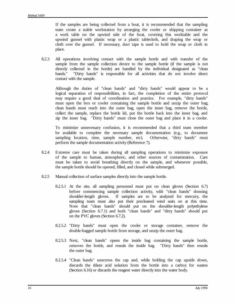
Method 1669
16 July 1996
If the samples are being collected from a boat, it is recommended that the samplingteam create a stable workstation by arranging the cooler or shipping container asa work table on the upwind side of the boat, covering this worktable and theupwind gunnel with plastic wrap or a plastic tablecloth, and draping the wrap orcloth over the gunnel. If necessary, duct tape is used to hold the wrap or cloth inplace.
8.2.3 All operations involving contact with the sample bottle and with transfer of thesample from the sample collection device to the sample bottle (if the sample is notdirectly collected in the bottle) are handled by the individual designated as "cleanhands." "Dirty hands" is responsible for all activities that do not involve directcontact with the sample.
Although the duties of "clean hands" and "dirty hands" would appear to be alogical separation of responsibilities, in fact, the completion of the entire protocolmay require a good deal of coordination and practice. For example, "dirty hands"must open the box or cooler containing the sample bottle and unzip the outer bag;clean hands must reach into the outer bag, open the inner bag, remove the bottle,collect the sample, replace the bottle lid, put the bottle back into the inner bag, andzip the inner bag. "Dirty hands" must close the outer bag and place it in a cooler.
To minimize unnecessary confusion, it is recommended that a third team memberbe available to complete the necessary sample documentation (e.g., to documentsampling location, time, sample number, etc). Otherwise, "dirty hands" mustperform the sample documentation activity (Reference 7).
8.2.4 Extreme care must be taken during all sampling operations to minimize exposureof the sample to human, atmospheric, and other sources of contamination. Caremust be taken to avoid breathing directly on the sample, and whenever possible,the sample bottle should be opened, filled, and closed while submerged.
8.2.5 Manual collection of surface samples directly into the sample bottle.
8.2.5.1 At the site, all sampling personnel must put on clean gloves (Section 6.7)before commencing sample collection activity, with "clean hands" donningshoulder-length gloves. If samples are to be analyzed for mercury, thesampling team must also put their precleaned wind suits on at this time.Note that "clean hands" should put on the shoulder-length polyethylenegloves (Section 6.7.1) and both "clean hands" and "dirty hands" should puton the PVC gloves (Section 6.7.2).
8.2.5.2 "Dirty hands" must open the cooler or storage container, remove thedouble-bagged sample bottle from storage, and unzip the outer bag.
8.2.5.3 Next, "clean hands" opens the inside bag containing the sample bottle,removes the bottle, and reseals the inside bag. "Dirty hands" then resealsthe outer bag.
8.2.5.4 "Clean hands" unscrews the cap and, while holding the cap upside down,discards the dilute acid solution from the bottle into a carboy for wastes(Section 6.16) or discards the reagent water directly into the water body.
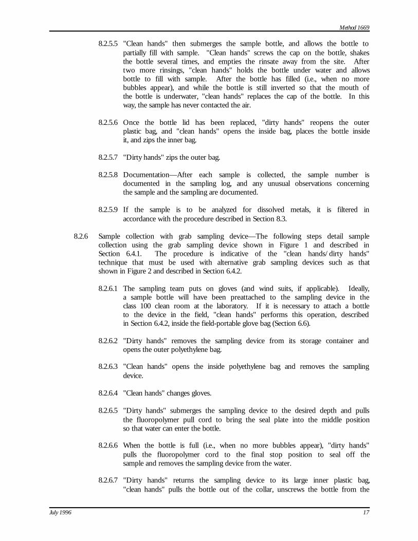
Method 1669
July 1996 17
8.2.5.5 "Clean hands" then submerges the sample bottle, and allows the bottle topartially fill with sample. "Clean hands" screws the cap on the bottle, shakesthe bottle several times, and empties the rinsate away from the site. Aftertwo more rinsings, "clean hands" holds the bottle under water and allowsbottle to fill with sample. After the bottle has filled (i.e., when no morebubbles appear), and while the bottle is still inverted so that the mouth ofthe bottle is underwater, "clean hands" replaces the cap of the bottle. In thisway, the sample has never contacted the air.
8.2.5.6 Once the bottle lid has been replaced, "dirty hands" reopens the outerplastic bag, and "clean hands" opens the inside bag, places the bottle insideit, and zips the inner bag.
8.2.5.7 "Dirty hands" zips the outer bag.
8.2.5.8 Documentation—After each sample is collected, the sample number isdocumented in the sampling log, and any unusual observations concerningthe sample and the sampling are documented.
8.2.5.9 If the sample is to be analyzed for dissolved metals, it is filtered inaccordance with the procedure described in Section 8.3.
8.2.6 Sample collection with grab sampling device—The following steps detail samplecollection using the grab sampling device shown in Figure 1 and described inSection 6.4.1. The procedure is indicative of the "clean hands/dirty hands"technique that must be used with alternative grab sampling devices such as thatshown in Figure 2 and described in Section 6.4.2.
8.2.6.1 The sampling team puts on gloves (and wind suits, if applicable). Ideally,a sample bottle will have been preattached to the sampling device in theclass 100 clean room at the laboratory. If it is necessary to attach a bottleto the device in the field, "clean hands" performs this operation, describedin Section 6.4.2, inside the field-portable glove bag (Section 6.6).
8.2.6.2 "Dirty hands" removes the sampling device from its storage container andopens the outer polyethylene bag.
8.2.6.3 "Clean hands" opens the inside polyethylene bag and removes the samplingdevice.
8.2.6.4 "Clean hands" changes gloves.
8.2.6.5 "Dirty hands" submerges the sampling device to the desired depth and pullsthe fluoropolymer pull cord to bring the seal plate into the middle positionso that water can enter the bottle.
8.2.6.6 When the bottle is full (i.e., when no more bubbles appear), "dirty hands"pulls the fluoropolymer cord to the final stop position to seal off thesample and removes the sampling device from the water.
8.2.6.7 "Dirty hands" returns the sampling device to its large inner plastic bag,"clean hands" pulls the bottle out of the collar, unscrews the bottle from the
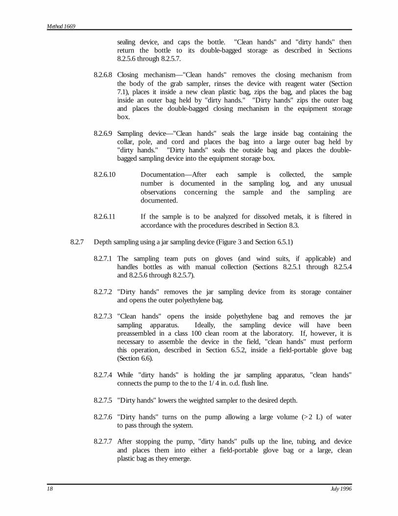
Method 1669
18 July 1996
sealing device, and caps the bottle. "Clean hands" and "dirty hands" thenreturn the bottle to its double-bagged storage as described in Sections8.2.5.6 through 8.2.5.7.
8.2.6.8 Closing mechanism—"Clean hands" removes the closing mechanism fromthe body of the grab sampler, rinses the device with reagent water (Section7.1), places it inside a new clean plastic bag, zips the bag, and places the baginside an outer bag held by "dirty hands." "Dirty hands" zips the outer bagand places the double-bagged closing mechanism in the equipment storagebox.
8.2.6.9 Sampling device—"Clean hands" seals the large inside bag containing thecollar, pole, and cord and places the bag into a large outer bag held by"dirty hands." "Dirty hands" seals the outside bag and places the double-bagged sampling device into the equipment storage box.
8.2.6.10 Documentation—After each sample is collected, the samplenumber is documented in the sampling log, and any unusualobservations concerning the sample and the sampling aredocumented.
8.2.6.11 If the sample is to be analyzed for dissolved metals, it is filtered inaccordance with the procedures described in Section 8.3.
8.2.7 Depth sampling using a jar sampling device (Figure 3 and Section 6.5.1)
8.2.7.1 The sampling team puts on gloves (and wind suits, if applicable) andhandles bottles as with manual collection (Sections 8.2.5.1 through 8.2.5.4and 8.2.5.6 through 8.2.5.7).
8.2.7.2 "Dirty hands" removes the jar sampling device from its storage containerand opens the outer polyethylene bag.
8.2.7.3 "Clean hands" opens the inside polyethylene bag and removes the jarsampling apparatus. Ideally, the sampling device will have beenpreassembled in a class 100 clean room at the laboratory. If, however, it isnecessary to assemble the device in the field, "clean hands" must performthis operation, described in Section 6.5.2, inside a field-portable glove bag(Section 6.6).
8.2.7.4 While "dirty hands" is holding the jar sampling apparatus, "clean hands"connects the pump to the to the 1/4 in. o.d. flush line.
8.2.7.5 "Dirty hands" lowers the weighted sampler to the desired depth.
8.2.7.6 "Dirty hands" turns on the pump allowing a large volume (>2 L) of waterto pass through the system.
8.2.7.7 After stopping the pump, "dirty hands" pulls up the line, tubing, and deviceand places them into either a field-portable glove bag or a large, cleanplastic bag as they emerge.

Method 1669
July 1996 19
8.2.7.8 Both "clean hands" and "dirty hands" change gloves.
8.2.7.9 Using the technique described in Sections 8.2.5.2 through 8.2.5.4, thesampling team removes a sample bottle from storage, and "clean hands"places the bottle into the glove bag.
8.2.7.10 "Clean hands" tips the sampling jar and dispenses the samplethrough the short length of fluoropolymer tubing into the samplebottle.
8.2.7.11 Once the bottle is filled, "clean hands" replaces the cap of the bottle,returns the bottle to the inside polyethylene bag, and zips the bag."Clean hands" returns the zipped bag to the outside polyethylenebag held by "dirty hands."
8.2.7.12 "Dirty hands" zips the outside bag. If the sample is to be analyzedfor dissolved metals, it is filtered as described in Section 8.3.
8.2.7.13 Documentation—After each sample is collected, the samplenumber is documented in the sampling log, and any unusualobservations concerning the sample and the sampling aredocumented.
8.2.8 Continuous-flow sampling (Figure 4 and Section 6.5.2)—The continuous-flowsampling system uses peristaltic pump (Section 6.15) to pump sample to the boator to shore through the SEBS-resin or PTFE tubing.
8.2.8.1 Before putting on wind suits or gloves, the sampling team removes the bagscontaining the pump (Section 6.15), SEBS-resin tubing (Section 6.15.2),batteries (Section 6.15.4), gloves (Section 6.7), plastic wrap (Section 6.9),wind suits (Section 6.12), and, if samples are to be filtered, the filtrationapparatus (Section 6.14) from the coolers or storage containers in whichthey are packed.
8.2.8.2 "Clean hands" and "dirty hands" put on the wind suits and PVC gloves(Section 6.7.2).
8.2.8.3 "Dirty hands" removes the pump from its storage bag, and opens the bagcontaining the SEBS-resin tubing.
8.2.8.4 "Clean hands" installs the tubing while "dirty hands" holds the pump."Clean hands" immerses the inlet end of the tubing in the sample stream.
8.2.8.5 Both "clean hands" and "dirty hands" change gloves. "Clean hands" alsoputs on shoulder length polyethylene gloves (Section 6.7.1).
8.2.8.6 "Dirty hands" turns the pump on and allows the pump to run for5-10 minutes or longer to purge the pump and tubing.
8.2.8.7 If the sample is to be filtered, "clean hands" installs the filter at the end ofthe tubing, and "dirty hands" sets up the filter holder on the gunwale asshown in Figure 4.
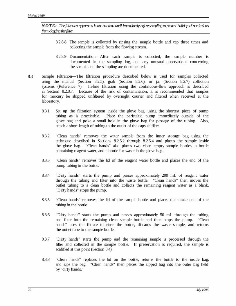
Method 1669
20 July 1996
NOTE: The filtration apparatus is not attached until immediately before sampling to prevent buildup of particulatesfrom clogging the filter.
8.2.8.8 The sample is collected by rinsing the sample bottle and cap three times andcollecting the sample from the flowing stream.
8.2.8.9 Documentation—After each sample is collected, the sample number isdocumented in the sampling log, and any unusual observations concerningthe sample and the sampling are documented.
8.3 Sample Filtration—The filtration procedure described below is used for samples collectedusing the manual (Section 8.2.5), grab (Section 8.2.6), or jar (Section 8.2.7) collectionsystems (Reference 7). In-line filtration using the continuous-flow approach is describedin Section 8.2.8.7. Because of the risk of contamination, it is recommended that samplesfor mercury be shipped unfiltered by overnight courier and filtered when received at thelaboratory.
8.3.1 Set up the filtration system inside the glove bag, using the shortest piece of pumptubing as is practicable. Place the peristaltic pump immediately outside of theglove bag and poke a small hole in the glove bag for passage of the tubing. Also,attach a short length of tubing to the outlet of the capsule filter.
8.3.2 "Clean hands" removes the water sample from the inner storage bag using thetechnique described in Sections 8.2.5.2 through 8.2.5.4 and places the sample insidethe glove bag. "Clean hands" also places two clean empty sample bottles, a bottlecontaining reagent water, and a bottle for waste in the glove bag.
8.3.3 "Clean hands" removes the lid of the reagent water bottle and places the end of thepump tubing in the bottle.
8.3.4 "Dirty hands" starts the pump and passes approximately 200 mL of reagent waterthrough the tubing and filter into the waste bottle. "Clean hands" then moves theoutlet tubing to a clean bottle and collects the remaining reagent water as a blank."Dirty hands" stops the pump.
8.3.5 "Clean hands" removes the lid of the sample bottle and places the intake end of thetubing in the bottle.
8.3.6 "Dirty hands" starts the pump and passes approximately 50 mL through the tubingand filter into the remaining clean sample bottle and then stops the pump. "Cleanhands" uses the filtrate to rinse the bottle, discards the waste sample, and returnsthe outlet tube to the sample bottle.
8.3.7 "Dirty hands" starts the pump and the remaining sample is processed through thefilter and collected in the sample bottle. If preservation is required, the sample isacidified at this point (Section 8.4).
8.3.8 "Clean hands" replaces the lid on the bottle, returns the bottle to the inside bag,and zips the bag. "Clean hands" then places the zipped bag into the outer bag heldby "dirty hands."
Method 1669
July 1996 21
8.3.9 "Dirty hands" zips the outer bag, and places the double-bagged sample bottle intoa clean, ice-filled cooler for immediate shipment to the laboratory.
NOTE: It is not advisable to reclean and reuse filters. The difficulty and risk associated with failing to properly cleanthese devices far outweighs the cost of purchasing a new filter.
8.4 Preservation
8.4.1 Field preservation is not necessary for dissolved metals, except for trivalent andhexavalent chromium, provided that the sample is preserved in the laboratory andallowed to stand for at least two days to allow the metals adsorbed to the containerwalls to redissolve. Field preservation is advised for hexavalent chromium in orderto provide sample stability for up to 30 days. Mercury samples should be shippedby overnight courier and preserved when received at the laboratory.
8.4.2 If field preservation is required, preservation must be performed in the glove bagor in a designated clean area, with gloved hands, as rapidly as possible to precludeparticulates from contaminating the sample. For preservation of trivalentchromium, the glove bag or designated clean area must be large enough toaccommodate the vacuum filtration apparatus (Section 6.17.3), and an area shouldbe available for setting up the wrist-action shaker (Section 6.17.5). It is alsoadvisable to set up a work area that contains a "clean" cooler for storage of cleanequipment, a "dirty" cooler for storage of "dirty" equipment, and a third cooler tostore samples for shipment to the laboratory.
8.4.3 Preservation of aliquots for metals other than trivalent and hexavalentchromium—Using a disposable, precleaned, plastic pipet, add 5 mL of a 10%solution of ultrapure nitric acid in reagent water per liter of sample. This will besufficient to preserve a neutral sample to pH <2.
8.4.4 Preservation of aliquots for trivalent chromium (References 8-9).
8.4.4.1 Decant 100 mL of the sample into a clean polyethylene bottle.
8.4.4.2 Clean an Eppendorf pipet by pipeting 1 mL of 10% HCl (Section (7.4.4)followed by 1 mL of reagent water into an acid waste container. Use therinsed pipet to add 1 mL of chromium (III) extraction solution (Section7.4.3) to each sample and blank.
8.4.4.3 Cap each bottle tightly, place in a clean polyethylene bag, and shake on awrist action shaker (Section 6.17.5) for one hour.
8.4.4.4 Vacuum-filter the precipitate through a 0.4 µm pretreated filter membrane(Section 6.17.2), using fluoropolymer forceps (Section 6.17.1) to handle themembrane, and a 47 mm vacuum filtration apparatus with a precleanedfilter holder (Section 6.17.3). After all sample has filtered, rinse the insideof the filter holder with approximately 15 mL of reagent water.
8.4.4.5 Using the fluoropolymer forceps, fold the membrane in half and then inquarters, taking care to avoid touching the side containing the filtrate to anysurface. (Folding is done while the membrane is sitting on the filter holderand allows easy placement of the membrane into the sample vial). Transfer
Method 1669
22 July 1996
the filter to a 30 mL fluoropolymer vial. If the fluoropolymer vial was notpre-equipped with the ultrapure nitric acid (Section 7.4.1), rinse the pipetby drawing and discharging 1 mL of 10% HCl followed by 1 mL of reagentwater into a waste container, and add 1 mL of ultrapure nitric acid to thesample vial.
8.4.4.6 Cap the vial and double-bag it for shipment to the laboratory.
8.4.4.7 Repeat Steps 8.4.4.4-8.4.4.6 for each sample, rinsing the fluoropolymerforceps and the pipet with 10% high-purity HCl followed by reagent waterbetween samples.
8.4.5 Preservation of aliquots for hexavalent chromium (Reference 20).
8.4.5.1 Decant 125 mL of sample into a clean polyethylene bottle.
8.4.5.2 Prepare an Eppendorf pipet by pipeting 1 mL of 10% HCl (Section 7.4.4)followed by 1 mL of reagent water into an acid waste container. Use therinsed pipet to add 1 mL NaOH to each 125 mL sample and blank aliquot.
8.4.5.3 Cap the vial(s) and double-bag for shipment to the laboratory.
9.0 Quality Assurance/Quality Control
9.1 The sampling team shall employ a strict quality assurance/ quality control (QA/QC)program. The minimum requirements of this program include the collection of equipmentblanks, field blanks, and field replicates. It is also desirable to include blind QC samplesas part of the program. If samples will be processed for trivalent chromiumdeterminations, the sampling team shall also prepare method blank, OPR, and MS/MSDsamples as described in Section 9.6.
9.2 The sampling team is permitted to modify the sampling techniques described in thismethod to improve performance or reduce sampling costs, provided that reliable analysesof samples are obtained and that samples and blanks are not contaminated. Each time amodification is made to the procedures, the sampling team is required to demonstrate thatthe modification does not result in contamination of field and equipment blanks. Therequirements for modification are given in Sections 9.3 and 9.4. Because the acceptabilityof a modification is based on the results obtained with the modification, the sampling teammust work with an analytical laboratory capable of making trace metals determinations todemonstrate equivalence.
9.3 Equipment Blanks
9.3.1 Before using any sampling equipment at a given site, the laboratory or equipmentcleaning contractor is required to generate equipment blanks to demonstrate thatthe equipment is free from contamination. Two types of equipment blanks arerequired: bottle blanks and sampling equipment blanks.
9.3.2 Equipment blanks must be run on all equipment that will be used in the field. If,for example, samples are to be collected using both a grab sampling device and thejar sampling device, then an equipment blank must be run on both pieces ofequipment.
Method 1669
July 1996 23
9.3.3 Equipment blanks are generated in the laboratory or at the equipment cleaningcontractor's facility by processing reagent water through the equipment using thesame procedures that are used in the field (Section 8.0). Therefore, the "cleanhands/dirty hands" technique used during field sampling should be followed whenpreparing equipment blanks at the laboratory or cleaning facility. In addition,training programs must require must require sampling personnel to collect a cleanequipment blank before performing on-site field activities.
9.3.4 Detailed procedures for collecting equipment blanks are given in the analyticalmethods referenced in Table 1.
9.3.5 The equipment blank must be analyzed using the procedures detailed in thereferenced analytical method (see Table 1). If any metal(s) of interest or anypotentially interfering substance is detected in the equipment blank at the minimumlevel specified in the referenced method, the source of contamination/interferencemust be identified and removed. The equipment must be demonstrated to be freefrom the metal(s) of interest before the equipment may be used in the field.
9.4 Field Blank
9.4.1 To demonstrate that sample contamination has not occurred during field samplingand sample processing, at least one field blank must be generated for every 10samples that are collected at a given site. Field blanks are collected before samplecollection.
9.4.2 Field blanks are generated by filling a large carboy or other appropriate containerwith reagent water (Section 7.1) in the laboratory, transporting the filled containerto the sampling site, processing the water through each of the sample processingsteps and equipment (e.g., tubing, sampling devices, filters, etc.) that will be usedin the field, collecting the field blank in one of the sample bottles, and shipping thebottle to the laboratory for analysis in accordance with the method(s) referencedin Table 1. For example, manual grab sampler field blanks are collected by directlysubmerging a sample bottle into the water, filling the bottle, and capping.Subsurface sampler field blanks are collected by immersing the tubing into thewater and pumping water into a sample container.
9.4.3 Filter the field blanks using the procedures described in Section 8.3.
9.4.4 If it is necessary to acid clean the sampling equipment between samples (Section10.0), a field blank should be collected after the cleaning procedures but before thenext sample is collected.
9.4.5 If trivalent chromium aliquots are processed, a separate field blank must becollected and processed through the sample preparation steps given inSections 8.4.4.1 through 8.4.4.6.
9.5 Field Duplicate
9.5.1 To assess the precision of the field sampling and analytical processes, at least onefield duplicate sample must be collected for every 10 samples that are collected ata given site.
Method 1669
24 July 1996
9.5.2 The field duplicate is collected either by splitting a larger volume into two aliquotsin the glove box, by using a sampler with dual inlets that allows simultaneouscollection of two samples, or by collecting two samples in rapid succession.
9.5.3 Field duplicates for dissolved metals determinations must be processed using theprocedures in Section 8.3. Field duplicates for trivalent chromium must beprocessed through the sample preparation steps given in Sections 8.4.4.1 through8.4.4.6.
9.6 Additional QC for Collection of Trivalent Chromium Aliquots
9.6.1 Method blank—The sampling team must prepare one method blank for every tenor fewer field samples. Each method blank is prepared using the steps in Sections8.4.4.1 through 8.4.4.6 on a 100 mL aliquot of reagent water (Section 7.1). Do notuse the procedures in Section 8.3 to process the method blank through the 0.45 µmfilter (Section 6.14.1), even if samples are being collected for dissolved metalsdeterminations.
9.6.2 Ongoing precision and recovery (OPR)—The sampling team must prepare oneOPR for every ten or fewer field samples. The OPR is prepared using the steps inSections 8.4.4.1 through 8.4.4.6 on the OPR standard (Section 7.4.7). Do not usethe procedures in Section 8.3 to process the OPR through the 0.45 µm filter(Section 6.14.1), even if samples are being collected for dissolved metalsdeterminations.
9.6.3 MS/MSD—The sampling team must prepare one MS and one MSD for every tenor fewer field samples.
9.6.3.1 If, through historical data, the background concentration of the sample canbe estimated, the MS and MSD samples should be spiked at a level of oneto five times the background concentration.
9.6.3.2 For samples in which the background concentration is unknown, the MSand MSD samples should be spiked at a concentration of 25 µg/L.
9.6.3.3 Prepare the matrix spike sample by spiking a 100-mL aliquot of samplewith 2.5 mL of the standard chromium spike solution (Section 7.4.6), andprocessing the MS through the steps in Sections 8.4.4.1 through 8.4.4.6.
9.6.3.4 Prepare the matrix spike duplicate sample by spiking a second 100-mLaliquot of the same sample with 2.5 mL of the standard chromium spikesolution, and processing the MSD through the steps in Sections 8.4.4.1through 8.4.4.6.
9.6.3.5 If field samples are collected for dissolved metals determinations, it isnecessary to process an MS and an MSD through the 0.45 µm filter asdescribed in Section 8.3.
10.0 Recleaning the Apparatus Between Samples
10.1 Sampling activity should be planned so that samples known or suspected to contain thelowest concentrations of trace metals are collected first with the samples known or
Method 1669
July 1996 25
suspected to contain the highest concentrations of trace metals collected last. In thismanner, cleaning of the sampling equipment between samples in unnecessary. If it is notpossible to plan sampling activity in this manner, dedicated sampling equipment should beprovided for each sampling event.
10.2 If samples are collected from adjacent sites (e.g., immediately upstream or downstream),rinsing of the sampling Apparatus with water that is to be sampled should be sufficient.
10.3 If it is necessary to cross a gradient (i.e., going from a high-concentration sample to a low-concentration sample), such as might occur when collecting at a second site, the followingprocedure may be used to clean the sampling equipment between samples:
10.3.1 In the glove bag, and using the "clean hands/dirty hands" procedure inSection 8.2.5, process the dilute nitric acid solution (Section 7.2) through theApparatus.
10.3.2 Dump the spent dilute acid in the waste carboy or in the waterbody away from thesampling point.
10.3.3 Process 1 L of reagent water through the Apparatus to rinse the equipment anddiscard the spent water.
10.3.4 Collect a field blank as described in Section 9.4.
10.3.5 Rinse the Apparatus with copious amounts of the ambient water sample andproceed with sample collection.
10.4 Procedures for recleaning trivalent chromium preservation equipment between samplesare described in Section 8.4.4.
11.0 Method Performance
Samples were collected in the Great Lakes during September–October 1994 using theprocedures in this sampling method.
12.0 Pollution Prevention
12.1 The only materials used in this method that could be considered pollutants are the acidsused in the cleaning of the Apparatus, the boat, and related materials. These acids are usedin dilute solutions in small amounts and pose little threat to the environment whenmanaged properly.
12.2 Cleaning solutions containing acids should be prepared in volumes consistent with use tominimize the disposal of excessive volumes of acid.
12.3 To the extent possible, the Apparatus used to collect samples should be cleaned andreused to minimize the generation of solid waste.
13.0 Waste Management
13.1 It is the sampling team's responsibility to comply with all federal, state, and localregulations governing waste management, particularly the discharge regulations, hazardous
Method 1669
26 July 1996
waste identification rules, and land disposal restrictions; and to protect the air, water, andland by minimizing and controlling all releases from field operations.
13.2 For further information on waste management, consult The Waste Management Manual forLaboratory Personnel and Less is Better—Laboratory Chemical Management for Waste Reduction, available fromthe American Chemical Society's Department of Government Relations and SciencePolicy, 1155 16th Street NW, Washington, DC 20036.
14.0 References
1. Adeloju, S.B. and Bond, A.M. "Influence of Laboratory Environment on the Precision andAccuracy of Trace Element Analysis," Anal. Chem. 1985, 57, 1728.
2. Berman, S.S. and Yeats, P.A. "Sampling of Seawater for Trace Metals," CRC Reviews inAnalytical Chemistry 1985, 16.
3. Bloom, N.S. "Ultra-Clean Sampling, Storage, and Analytical Strategies for the AccurateDetermination of Trace Metals in Natural Waters." Presented at the 16th Annual EPAConference on the Analysis of Pollutants in the Environment, Norfolk, VA, May 5, 1993.
4. Bruland, K.W. "Trace Elements in Seawater," Chemical Oceanography 1983, 8, 157.
5. Nriagu, J.O., Larson, G., Wong, H.K.T., and Azcue, J.M. "A Protocol for MinimizingContamination in the Analysis of Trace Metals in Great Lakes Waters," J. Great Lakes Research1993, 19, 175.
6. Patterson, C.C. and Settle, D.M. "Accuracy in Trace Analysis," in National Bureau of StandardsSpecial Publication 422; LaFleur, P.D., Ed., U.S. Government Printing Office, Washington, DC,1976.
7. "A Protocol for the Collection and Processing of Surface-Water Samples for SubsequentDetermination of Trace Elements, Nutrients, and Major Ions in Filtered Water"; Office ofWater Quality Technical Memorandum 94.09, Office of Water Quality, Water ResourcesDivision, U.S. Geological Survey, Reston, VA, Jan. 28, 1994.
8. Standard Operating Procedure No. 4-54, Revision 01, SOP for Concentration and Analysis ofChromium Species in Whole Seawater; Prepared by Battelle Ocean Sciences, Duxbury, MA for theU.S. Environmental Protection Agency Office of Marine Environmental Protection, OceanIncineration Research Program, 1987.
9. Cranston, R.E. and Murray, J.W. "The Determination of Chromium Species in NaturalWaters," Anal. Chem. Acta 1978, 99, 275.
10. Prothro, M.G. "Office of Water Policy and Technical Guidance on Interpretation andImplementation of Aquatic Life Metals Criteria"; EPA Memorandum to Regional WaterManagement and Environmental Services Division Directors, Oct. 1, 1993.
11. "Format for Method Documentation"; Distributed by the EPA EnvironmentalMonitoring Management Council, Washington, DC, Nov. 18, 1993.
12. Windom, H.L., Byrd, J.T., Smith, R.G., Jr., and Huan, F. "Inadequacy of NASQAN Datafor Assessing Metal Trends in the Nation's Rivers," Environ. Sci. Technol. 1991, 25, 1137.

Method 1669
July 1996 27
13. Zief, M. and Mitchell, J.W. "Contamination Control in Trace Metals Analysis," ChemicalAnalysis 1976, 47, Chapter 6.
14. Phillips, H., Shafer, M., Dean, P., Walker, M., and Armstrong, D. "Recommendations forTrace Metals Analysis of Natural Waters"; Wisconsin Department of Natural Resources:Madison, WI, May 1992.
15. Hunt, C.D. In Manual of Biological and Geochemical Techniques in Coastal Areas, 2nd ed.; Lambert, C.E.and Oviatt, C.A., Eds.; Marine Ecosystems Research Laboratory; Graduate School ofOceanography; The University of Rhode Island: Narragansett, RI, MERL Series, ReportNo. 1, Chapter IV.
16. Flegal, R. Summer 1994 San Francisco Bay Cruise, apparatus and procedures witnessedand videotaped by W. Telliard and T. Fieldsend, Sept. 15-16, 1994.
17. Watras, C. Wisconsin DNR procedures for mercury sampling in pristine lakes inWisconsin, witnessed and videotaped by D. Rushneck and L. Riddick, Sept. 9-10, 1994.
18. Horowitz, A.J., Kent A.E., and Colberg, M.R. "The Effect of Membrane FiltrationArtifacts on Dissolved Trace Element Concentrations," Wat. Res. 1992, 26, 53.
19. Engineering Support Branch Standard Operating Procedures and Quality Assurance Manual: 1986; U.S.Environmental Protection Agency. Region IV. Environmental Services Division: Athens,GA.
20. Grohse, P. Research Triangle Institute, Institute Drive, Building 6, Research Triangle Park,NC.
21. Methods 1624 and 1625, 40 CFR Part 136, Appendix A.
15.0 Glossary of Definitions and Purposes
These definitions and purposes are specific to this sampling method but have beenconformed to common usage as much as possible.
15.1 Ambient Water—Waters in the natural environment (e.g., rivers, lakes, streams, and otherreceiving waters), as opposed to effluent discharges.
15.2 Apparatus—The sample container and other containers, filters, filter holders, labware,tubing, pipets, and other materials and devices used for sample collection or samplepreparation, and that will contact samples, blanks, or analytical standards.
15.3 Equipment Blank—An aliquot of reagent water that is subjected in the laboratory to allaspects of sample collection and analysis, including contact with all sampling devices andapparatus. The purpose of the equipment blank is to determine if the sampling devices andapparatus for sample collection have been adequately cleaned before they are shipped tothe field site. An acceptable equipment blank must be achieved before the samplingdevices and Apparatus are used for sample collection.
15.4 Field Blank—An aliquot of reagent water that is placed in a sample container in thelaboratory, shipped to the field, and treated as a sample in all respects, including contactwith the sampling devices and exposure to sampling site conditions, filtration, storage,
Method 1669
28 July 1996
preservation, and all analytical procedures. The purpose of the field blank is to determinewhether the field or sample transporting procedures and environments have contaminatedthe sample.
15.5 Field Duplicates (FD1 and FD2)—Two identical aliquots of a sample collected in separatesample bottles at the same time and place under identical circumstances using a duel inletsampler or by splitting a larger aliquot and treated exactly the same throughout field andlaboratory procedures. Analyses of FD1 and FD2 give a measure of the precisionassociated with sample collection, preservation, and storage, as well as with laboratoryprocedures.
15.6 Matrix Spike (MS) and Matrix Spike Duplicate (MSD)—Aliquots of an environmentalsample to which known quantities of the analytes are added in the laboratory. The MS andMSD are analyzed exactly like a sample. Their purpose is to quantify the bias and precisioncaused by the sample matrix. The background concentrations of the analytes in the samplematrix must be determined in a separate aliquot and the measured values in the MS andMSD corrected for background concentrations.
15.7 May—This action, activity, or procedural step is optional.
15.8 May Not—This action, activity, or procedural step is prohibited.
15.9 Minimum Level (ML)—The lowest level at which the entire analytical system gives arecognizable signal and acceptable calibration point (Reference 21).
15.10 Must—This action, activity, or procedural step is required.
15.11 Reagent Water—Water demonstrated to be free from the metal(s) of interest andpotentially interfering substances at the MDL for that metal in the referenced method oradditional method.
15.12 Should—This action, activity, or procedural step is suggested but not required.
15.13 Trace-Metal Grade—Reagents that have been demonstrated to be free from the metal(s)of interest at the method detection limit (MDL) of the analytical method to be used fordetermination of this metal(s).
The term "trace-metal grade" has been used in place of "reagent grade" or "reagent"because acids and other materials labeled "reagent grade" have been shown to containconcentrations of metals that will interfere in the determination of trace metals at levelslisted in Table 1.
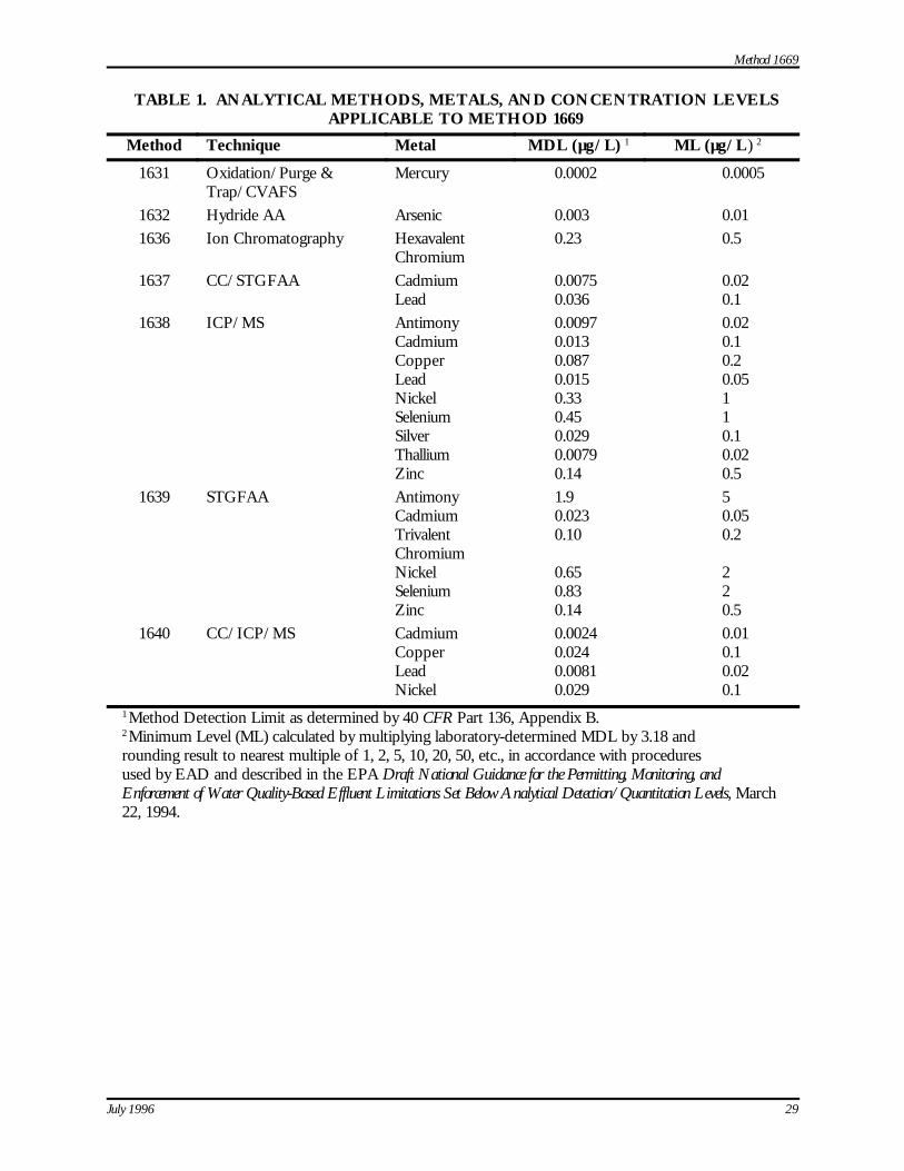
Method 1669
July 1996 29
TABLE 1. ANALYTICAL METHODS, METALS, AND CONCENTRATION LEVELSAPPLICABLE TO METHOD 1669
Method Technique Metal MDL (µg/L) 1 ML (µg/L) 2
1631 Oxidation/Purge &Trap/CVAFS
Mercury 0.0002 0.0005
1632 Hydride AA Arsenic 0.003 0.011636 Ion Chromatography Hexavalent
Chromium0.23 0.5
1637 CC/STGFAA Cadmium 0.0075 0.02Lead 0.036 0.1
1638 ICP/MS Antimony 0.0097 0.02Cadmium 0.013 0.1Copper 0.087 0.2Lead 0.015 0.05Nickel 0.33 1Selenium 0.45 1Silver 0.029 0.1Thallium 0.0079 0.02Zinc 0.14 0.5
1639 STGFAA Antimony 1.9 5Cadmium 0.023 0.05TrivalentChromium
0.10 0.2
Nickel 0.65 2Selenium 0.83 2Zinc 0.14 0.5
1640 CC/ICP/MS Cadmium 0.0024 0.01Copper 0.024 0.1Lead 0.0081 0.02Nickel 0.029 0.1
1 Method Detection Limit as determined by 40 CFR Part 136, Appendix B.2 Minimum Level (ML) calculated by multiplying laboratory-determined MDL by 3.18 androunding result to nearest multiple of 1, 2, 5, 10, 20, 50, etc., in accordance with proceduresused by EAD and described in the EPA Draft National Guidance for the Permitting, Monitoring, andEnforcement of Water Quality-Based Effluent Limitations Set Below Analytical Detection/Quantitation Levels, March22, 1994.
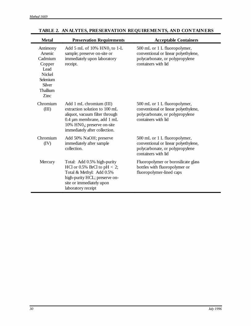
Method 1669
30 July 1996
TABLE 2. ANALYTES, PRESERVATION REQUIREMENTS, AND CONTAINERS
Metal Preservation Requirements Acceptable Containers
AntimonyArsenic
CadmiumCopper
LeadNickel
SeleniumSilver
ThalliumZinc
Add 5 mL of 10% HN03 to 1-Lsample; preserve on-site orimmediately upon laboratoryreceipt.
500 mL or 1 L fluoropolymer,conventional or linear polyethylene,polycarbonate, or polypropylenecontainers with lid
Chromium(III)
Add 1 mL chromium (III)extraction solution to 100 mLaliquot, vacuum filter through0.4 µm membrane, add 1 mL10% HN03; preserve on-siteimmediately after collection.
500 mL or 1 L fluoropolymer,conventional or linear polyethylene,polycarbonate, or polypropylenecontainers with lid
Chromium(IV)
Add 50% NaOH; preserveimmediately after samplecollection.
500 mL or 1 L fluoropolymer,conventional or linear polyethylene,polycarbonate, or polypropylenecontainers with lid
Mercury Total: Add 0.5% high-purityHCl or 0.5% BrCl to pH < 2;Total & Methyl: Add 0.5%high-purity HCL; preserve on-site or immediately uponlaboratory receipt
Fluoropolymer or borosilicate glassbottles with fluoropolymer orfluoropolymer-lined caps
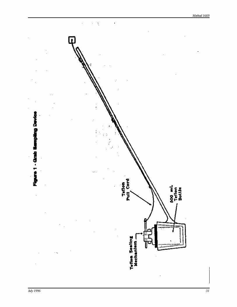
Method 1669
July 1996 31
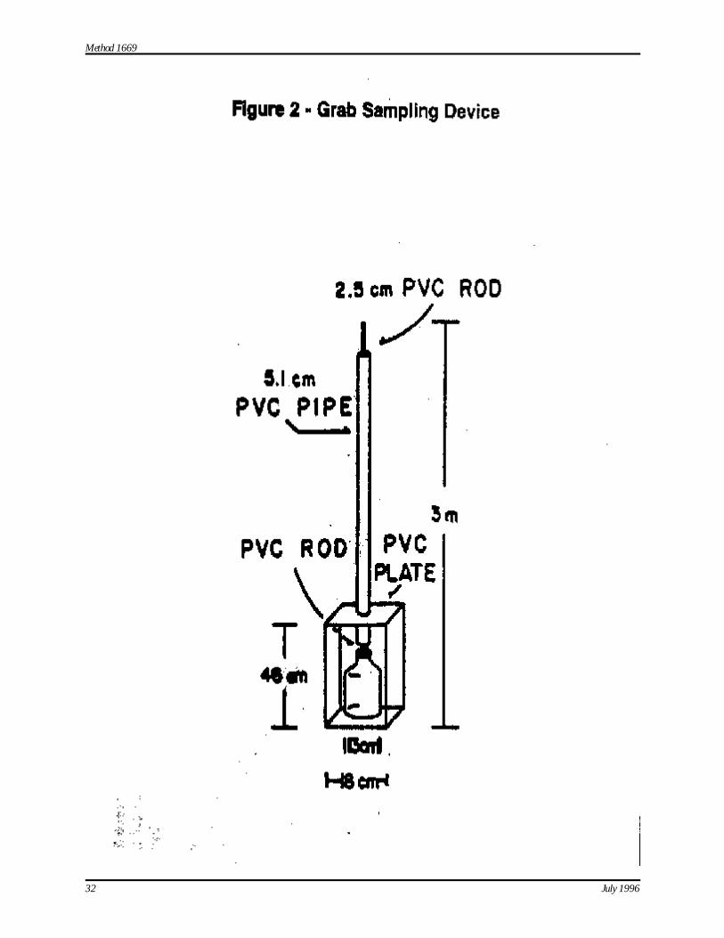
Method 1669
32 July 1996
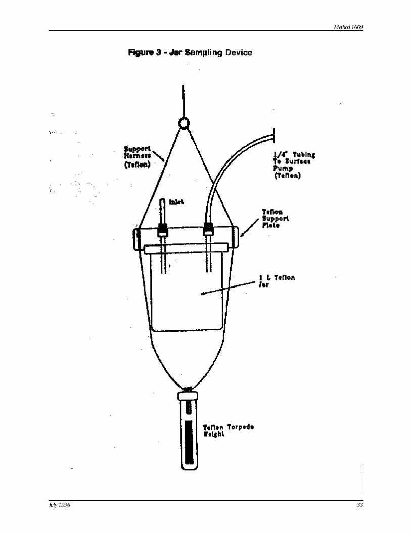
Method 1669
July 1996 33

Method 1669
34 July 1996