appendix b - mount specific data for … antenna controller appendix b - mount specific data b-1...
TRANSCRIPT

RC3000 Antenna Controller Appendix B - Mount Specific Data B-1
APPENDIX B - MOUNT SPECIFIC DATA For
Vertex/RSI 2.4 m SF-MOT (with resolvers)
This appendix describes RC3000 operations unique for the Vertex/RSI 2.4m. SF-MOT mount equipped with resolvers. Differences between this version and the operation described in the “baseline” RC3000 manual are noted on a paragraph by paragraph basis.
REVISION HISTORY
12 May 2006, Software Version 1.56c
1.1 Manual Organization
This appendix is provided as a supplement to the baseline RC3000 manual. The corresponding paragraphs in the baseline RC3000 manual are referred to when data specific to the SF-MOT mount with resolvers are described.
1.2 RC3000 Features
All basic features of the RC3000 are utilized to provide the operations for this mount. Some features have been modified (as described below) to customize operations for the SF-MOT (with resolvers) deployable antenna.
Hardware Configuration. A RC3000A version of hardware is utilized for this mount.
Software Configuration. The mount model will be designated as VK. Software will be designated as RC3K-VK-xxx.
1.3.2 System Interface Requirements
The VK interface differs from baseline RC3000 interface requirements as follows:
1) No limit switch feedback is provided from the azimuth or elevation axes
2) Resolvers present on the azimuth and elevation axes
3) No Polarization axis control
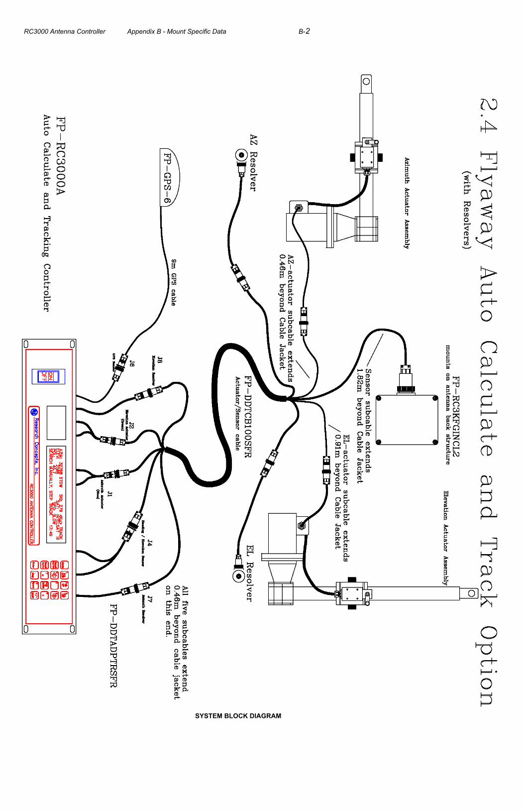
The following diagram shows the RC3000 connected to the relevant components of the VK mount system.
RC3000 Antenna Controller Appendix B - Mount Specific Data B-2
SYSTEM BLOCK DIAGRAM
RC3000 Antenna Controller Appendix B - Mount Specific Data B-3
1.3.3 Operational Overview
The baseline RC3000 modes are modified to accommodate the operational scenario for the VK mount. The following provides an overview of the intended operational sequence. Detailed description of the each mode will be provided in section 3.
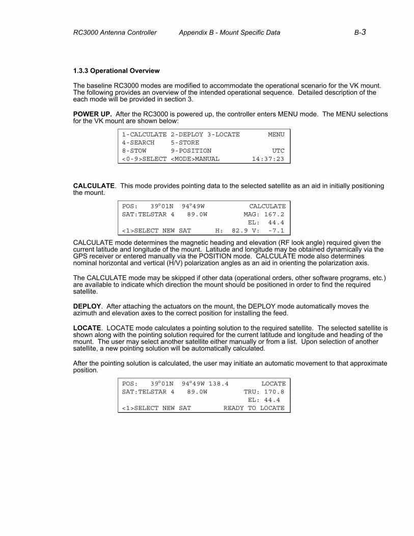
POWER UP. After the RC3000 is powered up, the controller enters MENU mode. The MENU selections for the VK mount are shown below:
1-CALCULATE 2-DEPLOY 3-LOCATE MENU 4-SEARCH 5-STORE 8-STOW 9-POSITION UTC <0-9>SELECT <MODE>MANUAL 14:37:23
CALCULATE. This mode provides pointing data to the selected satellite as an aid in initially positioning the mount.
POS: 39°01N 94°49W CALCULATE SAT:TELSTAR 4 89.0W MAG: 167.2 EL: 44.4 <1>SELECT NEW SAT H: 82.9 V: -7.1
CALCULATE mode determines the magnetic heading and elevation (RF look angle) required given the current latitude and longitude of the mount. Latitude and longitude may be obtained dynamically via the GPS receiver or entered manually via the POSITION mode. CALCULATE mode also determines nominal horizontal and vertical (H/V) polarization angles as an aid in orienting the polarization axis.
The CALCULATE mode may be skipped if other data (operational orders, other software programs, etc.) are available to indicate which direction the mount should be positioned in order to find the required satellite.
DEPLOY. After attaching the actuators on the mount, the DEPLOY mode automatically moves the azimuth and elevation axes to the correct position for installing the feed.
LOCATE. LOCATE mode calculates a pointing solution to the required satellite. The selected satellite is shown along with the pointing solution required for the current latitude and longitude and heading of the mount. The user may select another satellite either manually or from a list. Upon selection of another satellite, a new pointing solution will be automatically calculated.
After the pointing solution is calculated, the user may initiate an automatic movement to that approximate position.
POS: 39°01N 94°49W 138.4 LOCATE SAT:TELSTAR 4 89.0W TRU: 170.8 EL: 44.4 <1>SELECT NEW SAT READY TO LOCATE
RC3000 Antenna Controller Appendix B - Mount Specific Data B-4
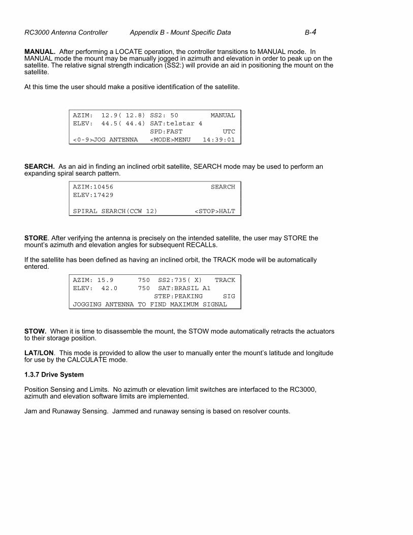
MANUAL. After performing a LOCATE operation, the controller transitions to MANUAL mode. In MANUAL mode the mount may be manually jogged in azimuth and elevation in order to peak up on the satellite. The relative signal strength indication (SS2:) will provide an aid in positioning the mount on the satellite.
At this time the user should make a positive identification of the satellite.
AZIM: 12.9( 12.8) SS2: 50 MANUAL ELEV: 44.5( 44.4) SAT:telstar 4 SPD:FAST UTC <0-9>JOG ANTENNA <MODE>MENU 14:39:01
SEARCH. As an aid in finding an inclined orbit satellite, SEARCH mode may be used to perform an expanding spiral search pattern.
AZIM:10456 SEARCH ELEV:17429 SPIRAL SEARCH(CCW 12) <STOP>HALT
STORE. After verifying the antenna is precisely on the intended satellite, the user may STORE the mount’s azimuth and elevation angles for subsequent RECALLs.
If the satellite has been defined as having an inclined orbit, the TRACK mode will be automatically entered.
AZIM: 15.9 750 SS2:735( X) TRACK ELEV: 42.0 750 SAT:BRASIL A1 STEP:PEAKING SIG JOGGING ANTENNA TO FIND MAXIMUM SIGNAL
STOW. When it is time to disassemble the mount, the STOW mode automatically retracts the actuators to their storage position.
LAT/LON. This mode is provided to allow the user to manually enter the mount’s latitude and longitude for use by the CALCULATE mode.
1.3.7 Drive System
Position Sensing and Limits. No azimuth or elevation limit switches are interfaced to the RC3000, azimuth and elevation software limits are implemented.
Jam and Runaway Sensing. Jammed and runaway sensing is based on resolver counts.

RC3000 Antenna Controller Appendix B - Mount Specific Data B-5
2.0 INSTALLATION
2.1 Equipment Mounting
As shown in the system diagram in 1.3.2, the fluxgate compass and the inclinometer are mounted together in a waterproof box. This box is mounted on the antenna’s structure in a level position when the antenna’s elevation RF look angle is 45 degrees.
2.2 Electrical Connections
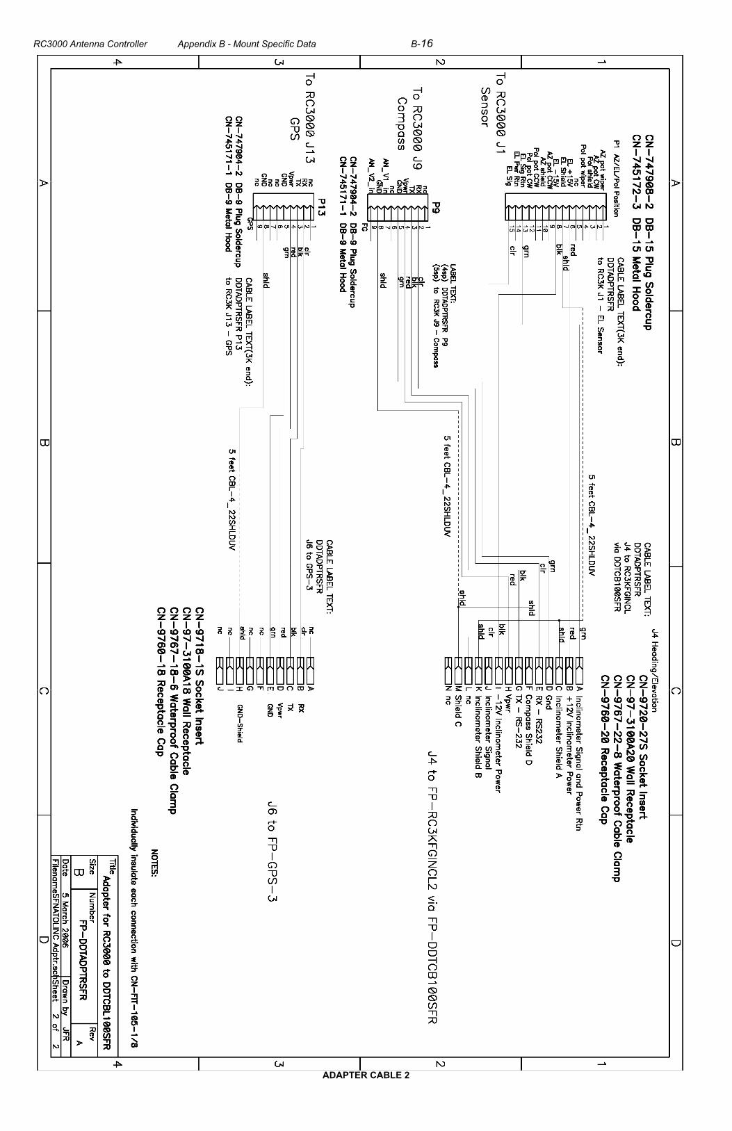
Electrical connections between the RC3000 and the VK mount are made via an RC3000 adapter cable (FP-DDTADPTRSFR) and a mount cable assembly (FP-DDTCB100SFR). The RC3000 adapter cable connects to the standard backplane connectors described in the baseline manual.
Schematics for the adapter cable and the mount cable are shown in section 4.2.
The following subparagraphs describe any unique items with respect to the VK system.
2.2.2 Motor Drive. No polarization axis drive.
2.2.3 Drive Sense. Only the elevation inclinometer interface is supported. The azimuth and polarization inputs are jumpered within the RC3000 so that azimuth or polarization limit conditions are not generated.
2.2.4 Limit Switches. The limit switch inputs are internally jumpered within the RC3000 since no limit switches on the mount are supplied to the controller.
2.2.5 Signal Strength. AGC channel 2 is to be wired to the Tracking Receiver as shown in this section of the baseline manual.
2.2.6 Navigation Sensors. The GPS receiver and Fluxgate Compass are wired as shown in the baseline manual.
2.2.7 Accessories. Outputs from this connector are available as described in the baseline manual.
2.2.8 RF Autopeak. This input is available but it is intended that only use the signal strength indication from the tracking receiver via AGC channel 2.
2.2.9 Hand Held Remote. This option is available.
2.2.11 PC Remote Control. The remote control interface is wired as shown in the baseline manual.
2.2.12 Waveguide Switch. The optional waveguide switch module is not provided.
RC3000 Antenna Controller Appendix B - Mount Specific Data B-6
2.3 Initial Configuration, 2.4 Final Calibration
Setup and calibration of the VK mount is somewhat unique compared to that described in the baseline manual for a vehicle mounted antenna. Two procedures (Factory Calibration and Operational Setup) are provided next to describe the unique actions required for the VK mount. The first procedure “Factory Calibration” describes the tasks required when first mating a controller to a particular antenna. The second “Operational Setup” describes the tasks required during an operational deployment of the mount.
Factory Calibration
2.3 Initial Calibration
2.3.1 Initialization
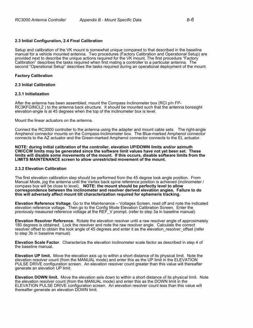
After the antenna has been assembled, mount the Compass Inclinometer box (RCI p/n FP-RC3KFGINCL2 ) to the antenna back structure. It should be mounted such that the antenna boresight elevation-angle is at 45 degrees when the top of the inclinometer box is level.
Mount the linear actuators on the antenna.
Connect the RC3000 controller to the antenna using the adapter and mount cable sets. The right-angle Amphenol connector mounts on the Compass-Inclinometer box. The Blue-marked Amphenol connector connects to the AZ actuator and the Green-marked Amphenol connector connects to the EL actuator.
NOTE: during initial calibration of the controller, elevation UP/DOWN limits and/or azimuth CW/CCW limits may be generated since the software limit values have not yet been set. These limits will disable some movements of the mount. If this occurs, disable software limits from the LIMITS MAINTENANCE screen to allow unrestricted movement of the mount.
2.3.2 Elevation Calibration
The first elevation calibration step should be performed from the 45 degree look angle position. From Manual Mode, jog the antenna until the Vertex back spine reference position is achieved (inclinometer / compass box will be close to level). NOTE: the mount should be perfectly level to allow correspondence between the inclinometer and resolver derived elevation angles. Failure to do this will adversely affect mount tilt characterization required for ephemeris tracking.
Elevation Reference Voltage. Go to the Maintenance – Voltages Screen, read off and note the indicated elevation reference voltage. Then go to the Config Mode Elevation Calibration Screen. Enter the previously measured reference voltage at the REF_V prompt. (refer to step 3a in baseline manual)
Elevation Resolver Reference. Rotate the elevation resolver until a raw resolver angle of approximately 180 degrees is obtained. Lock the resolver and note the raw resolver angle. Calculate the correct resolver offset to obtain the look angle of 45 degrees and enter it as the elevation_resolver_offset (refer to step 3b in baseline manual)
Elevation Scale Factor. Characterize the elevation inclinometer scale factor as described in step 4 of the baseline manual.
Elevation UP limit. Move the elevation axis up to within a short distance of its physical limit. Note the elevation resolver count (from the MANUAL mode) and enter this as the UP limit in the ELEVATION PULSE DRIVE configuration screen. An elevation resolver count greater than this value will thereafter generate an elevation UP limit.
Elevation DOWN limit. Move the elevation axis down to within a short distance of its physical limit. Note the elevation resolver count (from the MANUAL mode) and enter this as the DOWN limit in the ELEVATION PULSE DRIVE configuration screen. An elevation resolver count less than this value will thereafter generate an elevation DOWN limit.
RC3000 Antenna Controller Appendix B - Mount Specific Data B-7
2.3.3 Azimuth Calibration
The first azimuth calibration step should be performed from the azimuth center of travel position. From Manual Mode, jog the antenna until the azimuth is as close to this position as possible.
Azimuth Resolver Reference. Rotate the azimuth resolver until a raw resolver angle of approximately 180 degrees is obtained. Lock the resolver and note the raw resolver angle. Calculate the correct resolver offset to obtain an angle of 0.0 degrees and enter it as the elevation_resolver_offset (refer to step 3b in baseline manual)
Azimuth CW limit. Move the elevation axis clockwise to within a short distance of its physical limit. Note the azimuth resolver count (from the MANUAL mode) and enter this as the CW limit in the AZIMUTH PULSE DRIVE configuration screen. An azimuth resolver count greater than this value will thereafter generate an azimuth CW limit.
Azimuth CCW limit. Move the azimuth axis counterclockwise to within a short distance of its physical limit. Note the azimuth resolver count (from the MANUAL mode) and enter this as the CCW limit in the AZIMUTH PULSE DRIVE configuration screen. An azimuth resolver count less than this value will thereafter generate an azimuth CCW limit.
2.4.1 Compass Calibration
Perform a compass calibration from the MAINTENANCE Mode item #9, FLX CAL. This involves rotating the antenna and pausing at 8 points around a circle. Please refer to the RC3000 Manual Section 3.3.2.9 for further details. Note the CAL QUALITY and MAG ENVIRONMENT results displayed on the RC3000 after the calibration.
2.4.2 Azimuth and Elevation Alignment
As described in the baseline manual, perform a LOCATE to several known satellites. If necessary, correct any calibration values in order to achieve satisfactory automatic LOCATEs.
2.4.3 Signal Strength Adjustment
NOTE: The RC3000 will initially be calibrated to work with a signal strength input that varies between 0.0 (off satellite) to 10.0 (strongly on satellite) VDC.
Follow the RC3000 signal strength adjustment procedure described in the RC3000 manual Section 2.4.3. This procedure requires finding a strong satellite signal, measuring the beacon receiver output voltage and then looking at open space and measuring the output signal. Alternatively, a DC voltage of the correct level may be injected into the RC3000 AGC pin on J2. The nominal setup will use AGC channel 2 of the RC3000.
The factory setup procedure is complete. Once these items are set within a controller, the controller, compass/inclinometer box, and beacon receiver should be considered a matched set. If the compass/inclinometer box is swapped, the appropriate steps must be performed to match the two items. If the controller is swapped perform all steps.

RC3000 Antenna Controller Appendix B - Mount Specific Data B-8
Operational Setup
1) Deploy the electronics rack and turn on the power for the antenna controller. This will start the GPS receiver mounted near the electronics shelter and provide a Latitude-Longitude solution within a few minutes. The RC3000 CALCULATE ( MENU Mode #1) screen may be used to determine the magnetic compass bearing to the chosen satellite if it is not already known. If the GPS receiver is not setup at the time the CALCULATE is performed, the LAT.LON (MENU Mode #9 ) may be used to type-in a value for the antenna latitude and longitude.
2) Assemble the antenna to at least the point where the azimuth and elevation actuators are attached.
3) Connect the adapter and mount cables between the RC3000 and the antenna system. The five mount cables go to the AZ/EL actuators, AZ/EL resolvers and the Compass/Inclinometer Box mounted on the antenna back structure.
4) From the RC3000 MENU screen perform a DEPLOY ( #2) function. This will position the mount to a position where the feed system may be installed. While DEPLOY is operating, monitor the actuator positions and verify that there is no mechanical interference. Automated antenna motions may be interrupted at any time using the STOP key.
5) The antenna should be oriented such that the Azimuth range is centered in the direction of the chosen satellite. At this point the antenna should be fixed to the ground to allow further automatic locating and tracking operations.
6) From the Menu screen, perform a LOCATE ( #3) function using the chosen satellite. This will attempt to position the antenna on the selected satellite.
7) Verify that the satellite found is correct satellite.
8) If the satellite was not automatically found, search for the satellite from the MANUAL mode or alternatively, a spiral search may be implemented from the MENU screen (item #4).
9) If required, peakup on the satellite and set the polarization angle via the MANUAL mode. Verify that a received signal strength value greater that 200 is displayed on the RC3000 screen after SS2: .
10) From the MENU Screen, select the STORE (item #5). Verify that the satellite information is correct. If the satellite is an inclined orbit satellite, the controller will begin step-tracking.
11) The Controller will step-track for the first sidereal day and then drop into memory track mode. It will continue in memory track indefinitely.
12) When the operation is completed. The antenna can be disassembled according to the instructions. As an aid to disassembly, the STOW function (item #8) may be selected from the MENU mode. The STOW function returns the two actuators to their retraction limits.
RC3000 Antenna Controller Appendix B - Mount Specific Data B-9
3.0 Detailed Operation
3.1.1 Modes
While the basic functionality of the RC3000 is as described in the baseline manual, several modes are customized and several modes are unique for operation with the VK version mount.
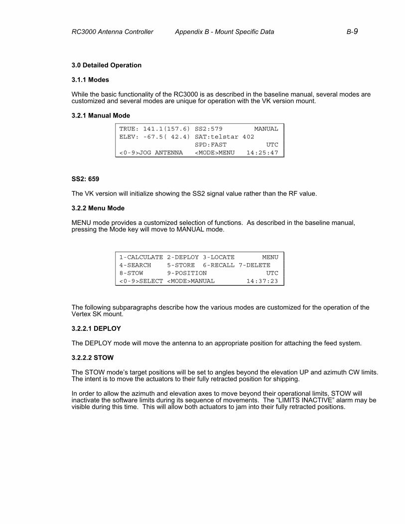
3.2.1 Manual Mode
TRUE: 141.1(157.6) SS2:579 MANUAL ELEV: -67.5( 42.4) SAT:telstar 402 SPD:FAST UTC <0-9>JOG ANTENNA <MODE>MENU 14:25:47
SS2: 659
The VK version will initialize showing the SS2 signal value rather than the RF value.
3.2.2 Menu Mode
MENU mode provides a customized selection of functions. As described in the baseline manual, pressing the Mode key will move to MANUAL mode.
1-CALCULATE 2-DEPLOY 3-LOCATE MENU 4-SEARCH 5-STORE 6-RECALL 7-DELETE 8-STOW 9-POSITION UTC <0-9>SELECT <MODE>MANUAL 14:37:23
The following subparagraphs describe how the various modes are customized for the operation of the Vertex SK mount.
3.2.2.1 DEPLOY
The DEPLOY mode will move the antenna to an appropriate position for attaching the feed system.
3.2.2.2 STOW
The STOW mode’s target positions will be set to angles beyond the elevation UP and azimuth CW limits. The intent is to move the actuators to their fully retracted position for shipping.
In order to allow the azimuth and elevation axes to move beyond their operational limits, STOW will inactivate the software limits during its sequence of movements. The “LIMITS INACTIVE” alarm may be visible during this time. This will allow both actuators to jam into their fully retracted positions.
RC3000 Antenna Controller Appendix B - Mount Specific Data B-10
3.2.2.3 LOCATE
Two versions of the LOCATE mode described in the baseline manual are provided for the VK mount. Unique characteristics of CALCULATE and LOCATE modes are described next.
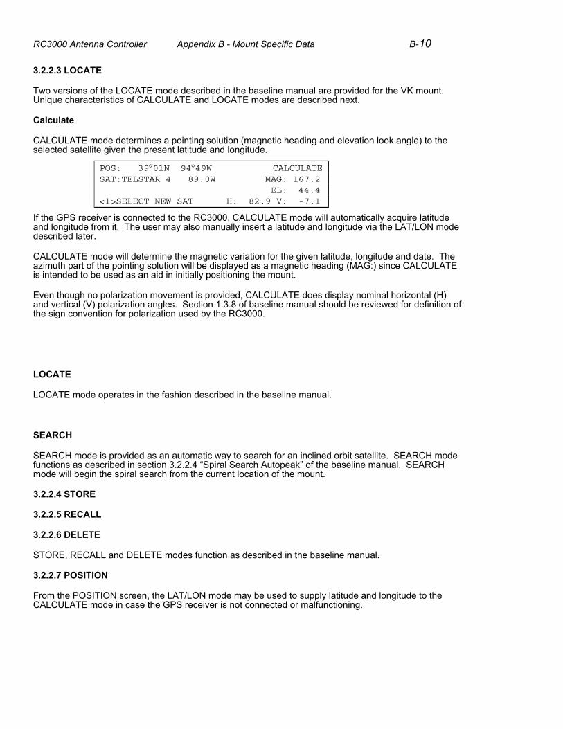
Calculate
CALCULATE mode determines a pointing solution (magnetic heading and elevation look angle) to the selected satellite given the present latitude and longitude.
POS: 39°01N 94°49W CALCULATE SAT:TELSTAR 4 89.0W MAG: 167.2 EL: 44.4 <1>SELECT NEW SAT H: 82.9 V: -7.1
If the GPS receiver is connected to the RC3000, CALCULATE mode will automatically acquire latitude and longitude from it. The user may also manually insert a latitude and longitude via the LAT/LON mode described later.
CALCULATE mode will determine the magnetic variation for the given latitude, longitude and date. The azimuth part of the pointing solution will be displayed as a magnetic heading (MAG:) since CALCULATE is intended to be used as an aid in initially positioning the mount.
Even though no polarization movement is provided, CALCULATE does display nominal horizontal (H) and vertical (V) polarization angles. Section 1.3.8 of baseline manual should be reviewed for definition of the sign convention for polarization used by the RC3000.
LOCATE
LOCATE mode operates in the fashion described in the baseline manual.
SEARCH
SEARCH mode is provided as an automatic way to search for an inclined orbit satellite. SEARCH mode functions as described in section 3.2.2.4 “Spiral Search Autopeak” of the baseline manual. SEARCH mode will begin the spiral search from the current location of the mount.
3.2.2.4 STORE
3.2.2.5 RECALL
3.2.2.6 DELETE
STORE, RECALL and DELETE modes function as described in the baseline manual.
3.2.2.7 POSITION
From the POSITION screen, the LAT/LON mode may be used to supply latitude and longitude to the CALCULATE mode in case the GPS receiver is not connected or malfunctioning.
RC3000 Antenna Controller Appendix B - Mount Specific Data B-11
3.2.2.8 SETTINGS
No SETTINGS mode is applicable to the operation of the VK mount.
NOTE: in case of an azimuth of elevation jammed condition, the axis may be reset via the DRIVE RESET mode described in section 3.3.2.2 of the baseline manual.
3.2.2.9 TRACK
3.2.2.10 REMOTE
TRACK and REMOTE modes perform as described in the baseline manual.
3.3 Programming Group
All programming group modes described in the baseline manual are provided.
3.3.1.2 Reset Defaults
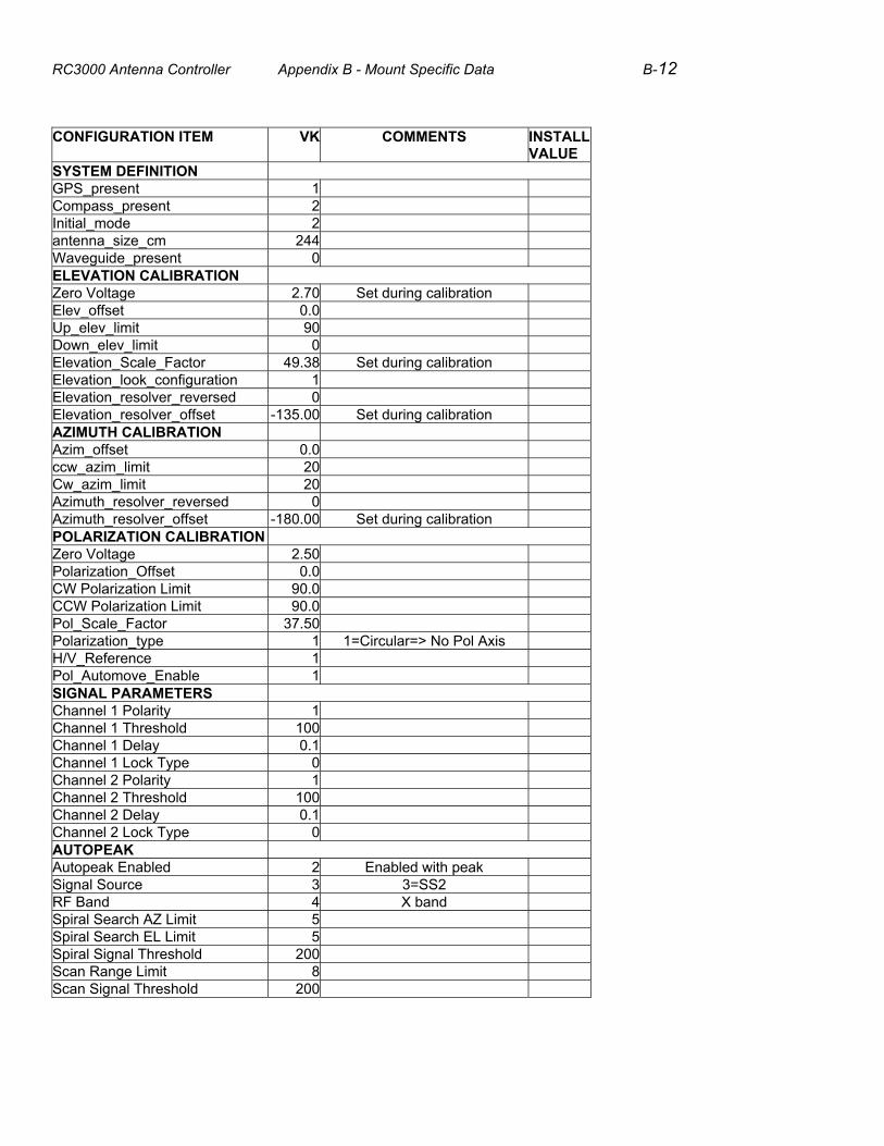
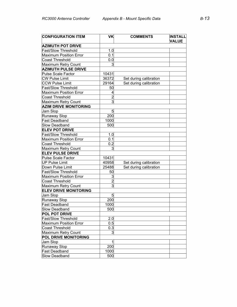
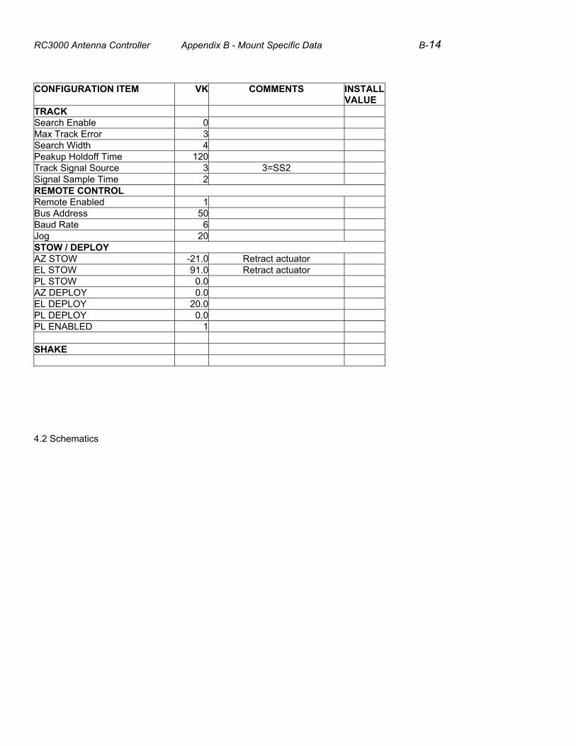
The following table supplies the default configuration item values for this mount. Space has also been provided to record installation specific changes to the configuration items. Note: recording of installation specific changes to defaults may prove valuable when trying to restore system configuration.
RC3000 Antenna Controller Appendix B - Mount Specific Data B-12
CONFIGURATION ITEM VK COMMENTS INSTALL VALUE
SYSTEM DEFINITION GPS_present 1 Compass_present 2 Initial_mode 2 antenna_size_cm 244 Waveguide_present 0 ELEVATION CALIBRATION Zero Voltage 2.70 Set during calibration Elev_offset 0.0 Up_elev_limit 90 Down_elev_limit 0 Elevation_Scale_Factor 49.38 Set during calibration Elevation_look_configuration 1 Elevation_resolver_reversed 0 Elevation_resolver_offset -135.00 Set during calibration AZIMUTH CALIBRATION Azim_offset 0.0 ccw_azim_limit 20 Cw_azim_limit 20 Azimuth_resolver_reversed 0 Azimuth_resolver_offset -180.00 Set during calibration POLARIZATION CALIBRATION Zero Voltage 2.50 Polarization_Offset 0.0 CW Polarization Limit 90.0 CCW Polarization Limit 90.0 Pol_Scale_Factor 37.50 Polarization_type 1 1=Circular=> No Pol Axis H/V_Reference 1 Pol_Automove_Enable 1 SIGNAL PARAMETERS Channel 1 Polarity 1 Channel 1 Threshold 100 Channel 1 Delay 0.1 Channel 1 Lock Type 0 Channel 2 Polarity 1 Channel 2 Threshold 100 Channel 2 Delay 0.1 Channel 2 Lock Type 0 AUTOPEAK Autopeak Enabled 2 Enabled with peak Signal Source 3 3=SS2 RF Band 4 X band Spiral Search AZ Limit 5 Spiral Search EL Limit 5 Spiral Signal Threshold 200 Scan Range Limit 8 Scan Signal Threshold 200
RC3000 Antenna Controller Appendix B - Mount Specific Data B-13
CONFIGURATION ITEM VK COMMENTS INSTALL VALUE
AZIMUTH POT DRIVE Fast/Slow Threshold 1.0 Maximum Position Error 0.1 Coast Threshold 0.0 Maximum Retry Count 3 AZIMUTH PULSE DRIVE Pulse Scale Factor 10431 CW Pulse Limit 36372 Set during calibration CCW Pulse Limit 29164 Set during calibration Fast/Slow Threshold 50 Maximum Position Error 4 Coast Threshold 2 Maximum Retry Count 3 AZIM DRIVE MONITORING Jam Slop 5 Runaway Slop 200 Fast Deadband 1000 Slow Deadband 500 ELEV POT DRIVE Fast/Slow Threshold 1.0 Maximum Position Error 0.1 Coast Threshold 0.2 Maximum Retry Count 3 ELEV PULSE DRIVE Pulse Scale Factor 10431 UP Pulse Limit 40958 Set during calibration Down Pulse Limit 25488 Set during calibration Fast/Slow Threshold 50 Maximum Position Error 3 Coast Threshold 2 Maximum Retry Count 3 ELEV DRIVE MONITORING Jam Slop 5 Runaway Slop 200 Fast Deadband 1000 Slow Deadband 500 POL POT DRIVE Fast/Slow Threshold 2.0 Maximum Position Error 0.5 Coast Threshold 0.3 Maximum Retry Count 3 POL DRIVE MONITORING Jam Slop 1 Runaway Slop 200 Fast Deadband 1000 Slow Deadband 500
RC3000 Antenna Controller Appendix B - Mount Specific Data B-14
CONFIGURATION ITEM VK COMMENTS INSTALL VALUE
TRACK Search Enable 0 Max Track Error 3 Search Width 4 Peakup Holdoff Time 120 Track Signal Source 3 3=SS2 Signal Sample Time 2 REMOTE CONTROL Remote Enabled 1 Bus Address 50 Baud Rate 6 Jog 20 STOW / DEPLOY AZ STOW -21.0 Retract actuator EL STOW 91.0 Retract actuator PL STOW 0.0 AZ DEPLOY 0.0 EL DEPLOY 20.0 PL DEPLOY 0.0 PL ENABLED 1 SHAKE
4.2 Schematics

RC3000 Antenna Controller Appendix B - Mount Specific Data B-15
ADAPTER CABLE 1
RC3000 Antenna Controller Appendix B - Mount Specific Data B-16
ADAPTER CABLE 2
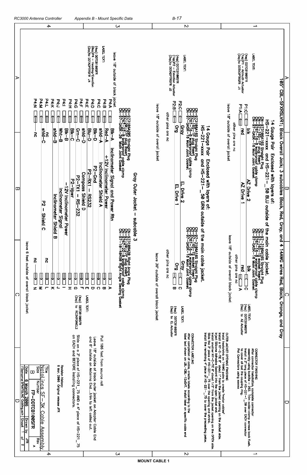
RC3000 Antenna Controller Appendix B - Mount Specific Data B-17
MOUNT CABLE 1

RC3000 Antenna Controller Appendix B - Mount Specific Data B-18
MOUNT CABLE 2