appendix b example problems
TRANSCRIPT
NCHRP Project 12-71 Design Specifications and Commentary for Horizontally Curved Concrete Box-Girder
Highway Bridges
Appendix B Example Problems
B-1

B-2
NCHRP Project 12-71
Design Specifications and Commentary for Horizontally Curved Concrete Box-Girder Highway Bridges
APPENDIX B - EXAMPLE PROBLEMS
TABLE OF CONTENTS
EXAMPLE B-1 – COMPREHENSIVE DESIGN EXAMPLE B-5 (SPINE AND GRILLAGE ANALYSIS)
1. PROBLEM DESCRIPTION B-5 2. ANALYSIS PARAMETERS B-9
a. Section Properties B-9 b. Loads B-13 c. LARSA Computer Input and Results B-15
3. SAMPLE CALCULATIONS B-35 a. Live Load Distribution Factors B-35 b. Longitudinal Prestress Check B-39 c. Section Check B-43 d. Bearing Forces B-56
4. LARSA GRILLAGE ANALOGY CHECK B-59 a. Analysis Parameters B-60 b. LARSA Computer Input and Output B-71 c. Longitudinal Prestress Check B-113 d. Section Check B-118 e. Bearing Forces B-120
EXAMPLE B-2 – TENDON CONFINEMENT B-121 EXAMPLE B-3 – TENDON CONFINEMENT B-131 EXAMPLE B-4 – GLOBAL PLUS REGIONAL COMBINATION B-137 (MENN) EXAMPLE B-5 – GLOBAL PLUS REGIONAL COMBINATION B-147 (PODOLNY) EXAMPLE B-6 – DEVIATION SADDLE DESIGN B-149

B-4
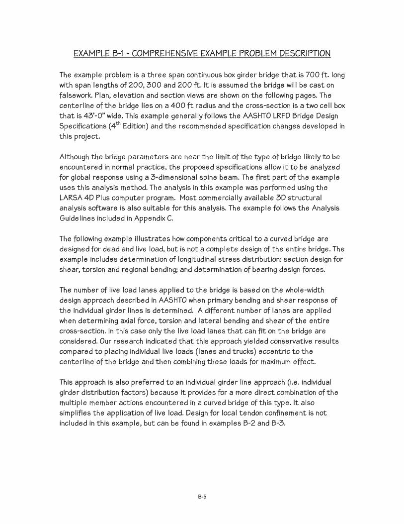
EXAMPLE B-1 - COMPREHENSIVE EXAMPLE PROBLEM DESCRIPTION The example problem is a three span continuous box girder bridge that is 700 ft. long with span lengths of 200, 300 and 200 ft. It is assumed the bridge will be cast on falsework. Plan, elevation and section views are shown on the following pages. The centerline of the bridge lies on a 400 ft radius and the cross-section is a two cell box that is 43’-0” wide. This example generally follows the AASHTO LRFD Bridge Design Specifications (4th Edition) and the recommended specification changes developed in this project. Although the bridge parameters are near the limit of the type of bridge likely to be encountered in normal practice, the proposed specifications allow it to be analyzed for global response using a 3-dimensional spine beam. The first part of the example uses this analysis method. The analysis in this example was performed using the LARSA 4D Plus computer program. Most commercially available 3D structural analysis software is also suitable for this analysis. The example follows the Analysis Guidelines included in Appendix C. The following example illustrates how components critical to a curved bridge are designed for dead and live load, but is not a complete design of the entire bridge. The example includes determination of longitudinal stress distribution; section design for shear, torsion and regional bending; and determination of bearing design forces. The number of live load lanes applied to the bridge is based on the whole-width design approach described in AASHTO when primary bending and shear response of the individual girder lines is determined. A different number of lanes are applied when determining axial force, torsion and lateral bending and shear of the entire cross-section. In this case only the live load lanes that can fit on the bridge are considered. Our research indicated that this approach yielded conservative results compared to placing individual live loads (lanes and trucks) eccentric to the centerline of the bridge and then combining these loads for maximum effect. This approach is also preferred to an individual girder line approach (i.e. individual girder distribution factors) because it provides for a more direct combination of the multiple member actions encountered in a curved bridge of this type. It also simplifies the application of live load. Design for local tendon confinement is not included in this example, but can be found in examples B-2 and B-3.
B-5
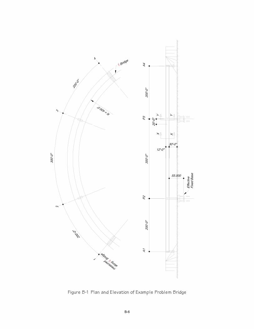
Figure B-1 Plan and Elevation of Example Problem Bridge
B-6

80 100 20 30 120
Abu
t 1
Ben
t 2
Sym
etric
Abo
ut
9'-6"6'-0"
1'-9"
10'-4"
C.G.
Mid
span
Spa
n 2
P = 16,347 kips (Use 4 - 31 strand tendons per web)JACK
Figure B-2 Prestress Path
B-7
In addition to the 3-dimensional spine beam analysis, a grillage analogy analysis, also performed with LARSA 4D Plus, is presented. This analysis would not be required by the proposed specifications for this bridge, but is included to illustrate the analysis technique and for comparison of results.
B-8
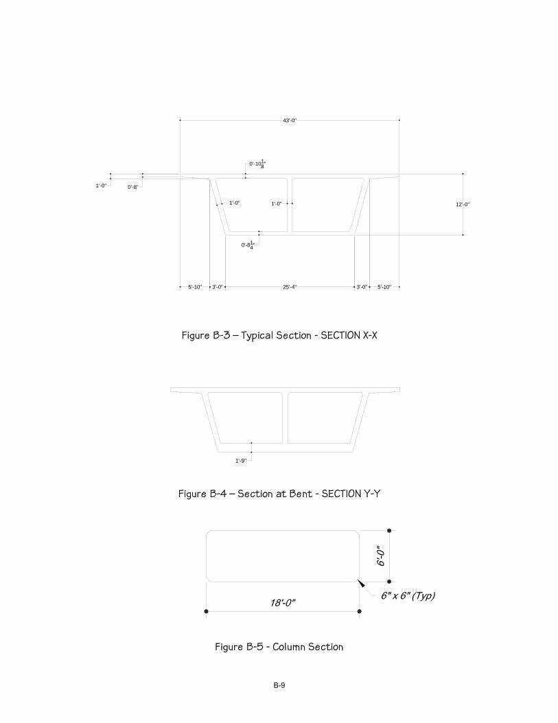
43'-0"
5'-10" 3'-0" 25'-4" 3'-0" 5'-10"
0'-8"1'-0"
0'-1018"
0'-814"
12'-0"1'-0" 1'-0"
Figure B-3 – Typical Section - SECTION X-X
1'-9"
Figure B-4 – Section at Bent - SECTION Y-Y
Figure B-5 - Column Section
B-9
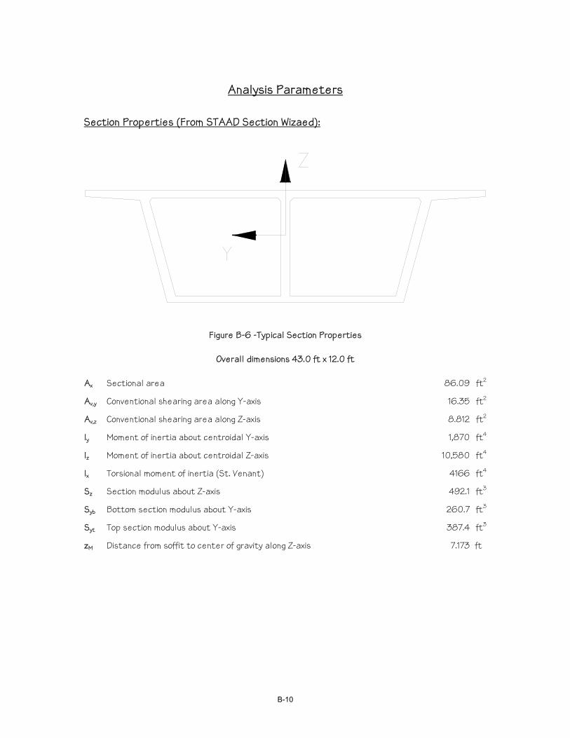
Analysis Parameters
Section Properties (From STAAD Section Wizaed):
Figure B-6 -Typical Section Properties
Overall dimensions 43.0 ft x 12.0 ft
Ax Sectional area 86.09 ft2
Av,y Conventional shearing area along Y-axis 16.35 ft2
Av,z Conventional shearing area along Z-axis 8.812 ft2
Iy Moment of inertia about centroidal Y-axis 1,870 ft4
Iz Moment of inertia about centroidal Z-axis 10,580 ft4
Ix Torsional moment of inertia (St. Venant) 4166 ft4
Sz Section modulus about Z-axis 492.1 ft3
Syb Bottom section modulus about Y-axis 260.7 ft3
Syt Top section modulus about Y-axis 387.4 ft3
zM Distance from soffit to center of gravity along Z-axis 7.173 ft
B-10
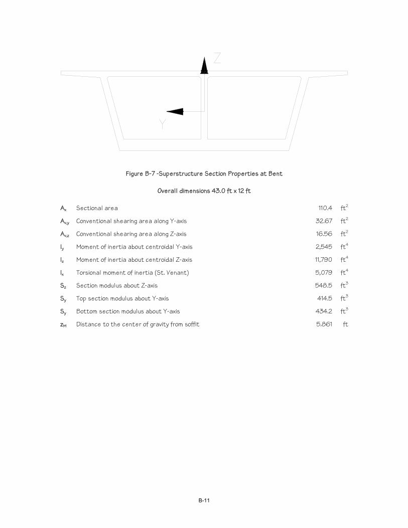
Figure B-7 -Superstructure Section Properties at Bent
Overall dimensions 43.0 ft x 12 ft
Ax Sectional area 110.4 ft2
Av,y Conventional shearing area along Y-axis 32.67 ft2
Av,z Conventional shearing area along Z-axis 16.56 ft2
Iy Moment of inertia about centroidal Y-axis 2,545 ft4
Iz Moment of inertia about centroidal Z-axis 11,790 ft4
Ix Torsional moment of inertia (St. Venant) 5,079 ft4
Sz Section modulus about Z-axis 548.5 ft3
Sy Top section modulus about Y-axis 414.5 ft3
Sy Bottom section modulus about Y-axis 434.2 ft3
zM Distance to the center of gravity from soffit 5.861 ft
B-11

Z
Y
Figure B-8 -Pier Section Properties
Overall dimensions 18.0 ft x 6.0 ft
Ax Sectional area 107.5 ft2
Av,z Conventional shearing area along Z-axis 81.25 ft2
Av,y Conventional shearing area along Y-axis 89.62 ft2
Iy Moment of inertia about centroidal Y-axis 320.0 ft4
Iz Moment of inertia about centroidal Z-axis 2877 ft4
Ix Torsional moment of inertia (St. Venant) 996.2 ft4
Sz Section modulus about Z-axis 319.7 ft3
Sy Section modulus about Y-axis 106.7 ft3
B-12

Loads: DC: Based on 150 pcf and member cross-section areas. Abutment Diaphragms = (ACP-AX) x WD x .150 = (352.76 – 86.09) x 4.0 x .150
= 160 kips
DW: wDW = WDECK(wOVERLAY) + 2wRAIL =43.0(.035) +2(0.5) = 2.51 kips/ft PSFINAL: PJACK = NSTRAND*ASTRAND*fPS*0.75 = 31*3*4*(.217)(270)(.75) = 16,347 kips Anchor Set = 0.375 inches μ = 0.2 κ = .0002 Use Low Relaxation Strand fc’ – 5000 psi Live Load Truck: Use HL93 with LARSA Live Load generator. Use one design truck
per bridge and scale results by number of factored design lanes (NL) as determined on page B-37
Live Load Lane: Use 0.64 kips/ft/lane. Use one lane and scale results by number
of factored design lanes (NL) as determined on page B-37. The maximum response from the following load cases and combinations was used.
LLA
LLB
LLC
LLD = LLA + LLB
LLE = LLB + LLC
LLF = LLA + LLB + LLC
Figure B-9 – Elevation of Bridge Showing Positions of Live Load Lane Loadings
IM: Vehicle dynamic effect on design truck = 0.33
B-13

B-14
Global Spine Beam Analysis Input and Results
LARSA Computer Output
B-15

B-16
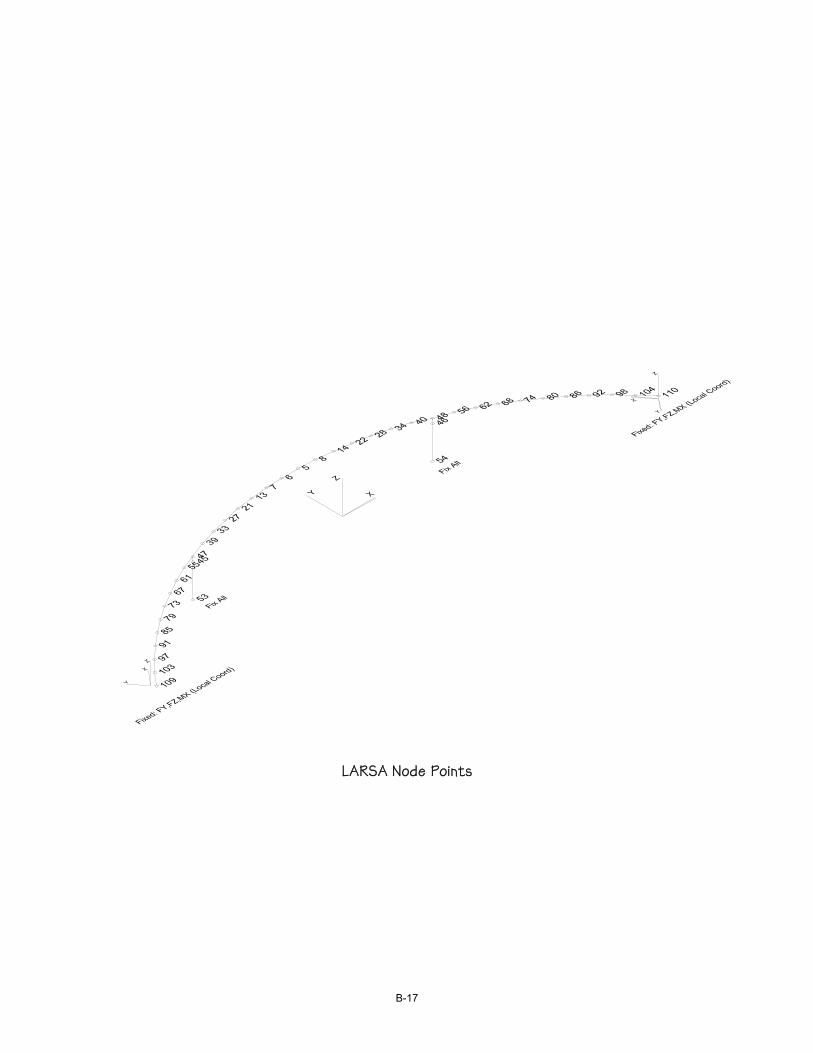
LARSA Node Points
B-17
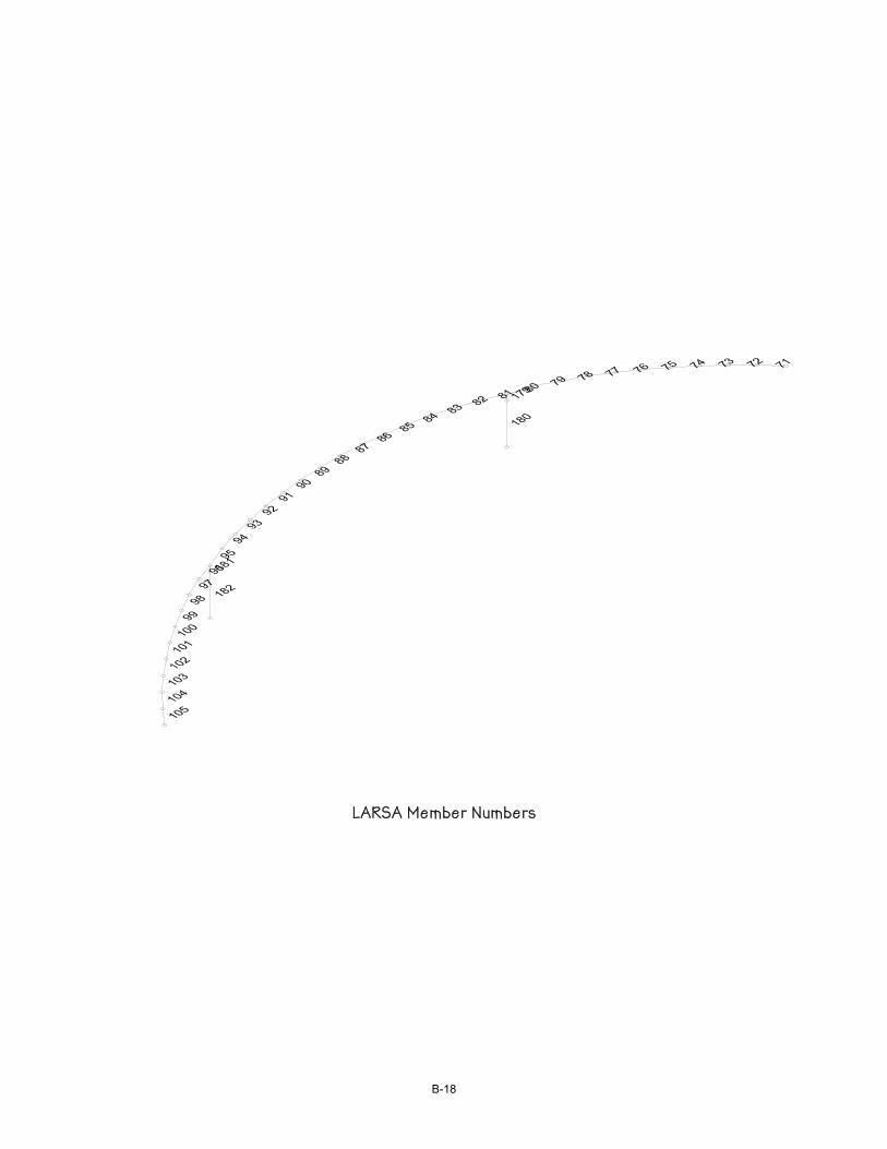
LARSA Member Numbers
B-18
Name Modulus of
Elasticity (lb/in²) Poisson Ratio Shear Modulus
(lb/in²) Unit Weight (lb/in³)Thermal Expansion (1/
°F *10^-6) Assigned
Fc_5 4031000 0.1704 1722000 0.0868 5.5 YesWEIGHTLESS 4031000 0.1704 1722000 0 5.5 Yes
PSS 28500000 0.29 11000000 0.278 5.5 Yes
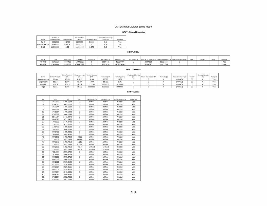
Name Type Origin X (ft) Origin Y (ft) Origin Z (ft) Axis Point X (ft) Axis Point Y (ft) Axis Point Z (ft) Point on XY Plane X (ft) Point on XY Plane Y (ft) Point on XY Plane Z (ft) Angle Z Angle X Angle Y Assigned
ABUT1 Cartesian 319.7489 -1608.5897 0 332.9472 -1593.5656 0 309.6219 -1600.1323 0 YesABUT4 Cartesian 933.7837 -1608.5897 0 920.5854 -1593.5656 0 923.6567 -1617.047 0 Yes
Name Section Area (ft²)Shear Area in yy
(ft²)Shear Area in zz
(ft²)Torsion Constant
(ft^4) Inertia Izz (ft^4) Inertia Iyy (ft^4)Plastic Modulus Zyy
(ft³) Plastic Modulus Zzz (ft³) Perimeter (ft) Creep/Shrinkage Type Ductility Residual Strength
(%) Assigned
Superstructure 86.09 16.35 8.812 4166 10580 1870 0 0 0 (NONE) 50 0 YesSuperBent 110.4 16.56 32.67 5079 11790 2545 0 0 0 (NONE) 50 0 Yes
Column 107.5 107.5 107.5 1279.92 2876.979 319.979 0 0 0 (NONE) 50 0 YesRigid 107.5 107.5 107.5 1000000 1000000 1000000 0 0 0 (NONE) 50 0 Yes
ID X (ft) Y (ft) Z (ft) Translation DOF Rotation DOF Displacement UCS Assignment
5 636.7653 -1465.1134 0 all free all free Global Yes6 616.4375 -1465.1218 0 all free all free Global Yes7 596.7944 -1466.1129 0 all free all free Global Yes8 656.7382 -1466.1129 0 all free all free Global Yes13 576.8964 -1468.1093 0 all free all free Global Yes14 676.6362 -1468.1093 0 all free all free Global Yes21 557.123 -1471.0978 0 all free all free Global Yes22 696.4096 -1471.0978 0 all free all free Global Yes27 537.5238 -1475.0708 0 all free all free Global Yes28 716.0088 -1475.0708 0 all free all free Global Yes33 518.1475 -1480.0183 0 all free all free Global Yes34 735.3851 -1480.0183 0 all free all free Global Yes39 499.0428 -1485.9281 0 all free all free Global Yes40 754.4898 -1485.9281 0 all free all free Global Yes45 480.2573 -1492.7853 -6.899 all free all free Global Yes46 773.2753 -1492.7853 -6.899 all free all free Global Yes47 480.2573 -1492.7853 -1.312 all free all free Global Yes48 773.2753 -1492.7853 -1.312 all free all free Global Yes53 480.2573 -1492.7853 -46.9 all fixed all fixed Global Yes54 773.2753 -1492.7853 -46.9 all fixed all fixed Global Yes55 461.838 -1500.5729 0 all free all free Global Yes56 791.6946 -1500.5729 0 all free all free Global Yes61 443.8309 -1509.2713 0 all free all free Global Yes62 809.7017 -1509.2713 0 all free all free Global Yes67 426.2811 -1518.8588 0 all free all free Global Yes68 827.2515 -1518.8588 0 all free all free Global Yes73 409.2324 -1529.3115 0 all free all free Global Yes74 844.3002 -1529.3115 0 all free all free Global Yes79 392.7274 -1540.6031 0 all free all free Global Yes80 860.8052 -1540.6031 0 all free all free Global Yes85 376.8074 -1552.7056 0 all free all free Global Yes86 876.7252 -1552.7056 0 all free all free Global Yes
LARSA Input Data for Spine Model
INPUT : Joints
INPUT : UCSs
INPUT : Material Properties
INPUT : Sections
B-19
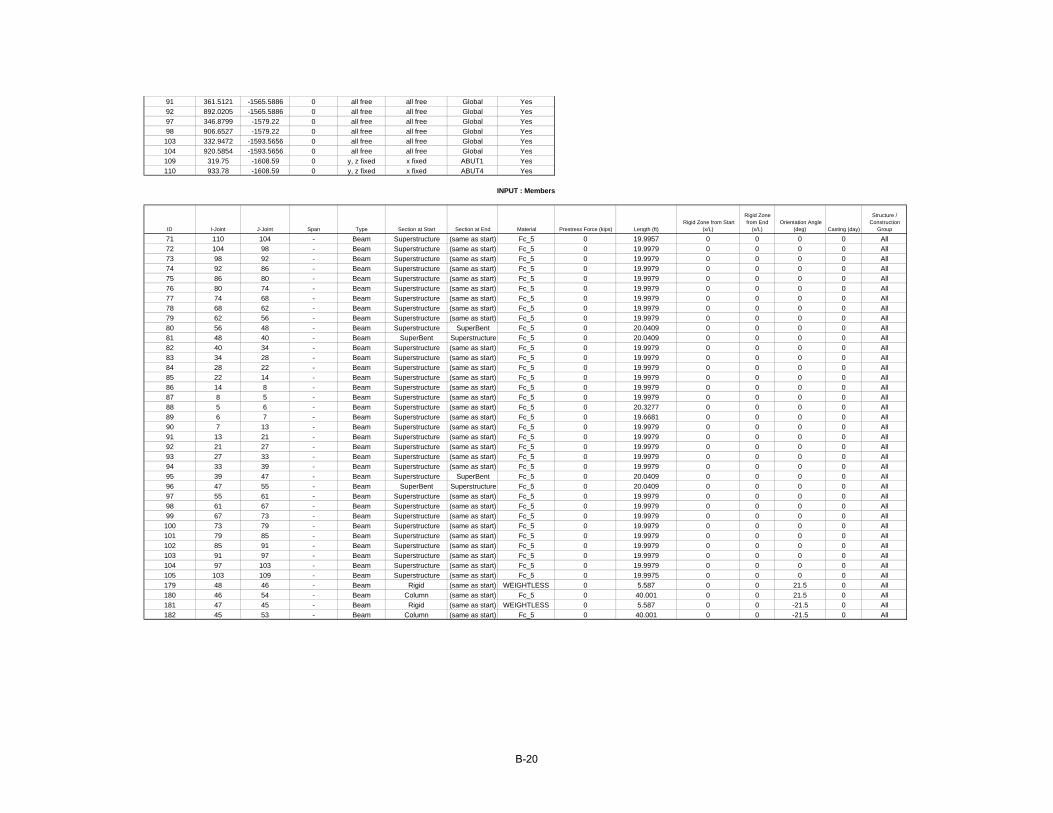
91 361.5121 -1565.5886 0 all free all free Global Yes92 892.0205 -1565.5886 0 all free all free Global Yes97 346.8799 -1579.22 0 all free all free Global Yes98 906.6527 -1579.22 0 all free all free Global Yes103 332.9472 -1593.5656 0 all free all free Global Yes104 920.5854 -1593.5656 0 all free all free Global Yes109 319.75 -1608.59 0 y, z fixed x fixed ABUT1 Yes110 933.78 -1608.59 0 y, z fixed x fixed ABUT4 Yes
ID I-Joint J-Joint Span Type Section at Start Section at End Material Prestress Force (kips) Length (ft)Rigid Zone from Start
(x/L)
Rigid Zone from End
(x/L)Orientation Angle
(deg) Casting (day)
Structure / Construction
Group
71 110 104 - Beam Superstructure (same as start) Fc_5 0 19.9957 0 0 0 0 All72 104 98 - Beam Superstructure (same as start) Fc_5 0 19.9979 0 0 0 0 All73 98 92 - Beam Superstructure (same as start) Fc_5 0 19.9979 0 0 0 0 All74 92 86 - Beam Superstructure (same as start) Fc_5 0 19.9979 0 0 0 0 All75 86 80 - Beam Superstructure (same as start) Fc_5 0 19.9979 0 0 0 0 All76 80 74 - Beam Superstructure (same as start) Fc_5 0 19.9979 0 0 0 0 All77 74 68 - Beam Superstructure (same as start) Fc_5 0 19.9979 0 0 0 0 All78 68 62 - Beam Superstructure (same as start) Fc_5 0 19.9979 0 0 0 0 All79 62 56 - Beam Superstructure (same as start) Fc_5 0 19.9979 0 0 0 0 All80 56 48 - Beam Superstructure SuperBent Fc_5 0 20.0409 0 0 0 0 All81 48 40 - Beam SuperBent Superstructure Fc_5 0 20.0409 0 0 0 0 All82 40 34 - Beam Superstructure (same as start) Fc_5 0 19.9979 0 0 0 0 All83 34 28 - Beam Superstructure (same as start) Fc_5 0 19.9979 0 0 0 0 All84 28 22 - Beam Superstructure (same as start) Fc_5 0 19.9979 0 0 0 0 All85 22 14 - Beam Superstructure (same as start) Fc_5 0 19.9979 0 0 0 0 All86 14 8 - Beam Superstructure (same as start) Fc_5 0 19.9979 0 0 0 0 All87 8 5 - Beam Superstructure (same as start) Fc_5 0 19.9979 0 0 0 0 All88 5 6 - Beam Superstructure (same as start) Fc_5 0 20.3277 0 0 0 0 All89 6 7 - Beam Superstructure (same as start) Fc_5 0 19.6681 0 0 0 0 All90 7 13 - Beam Superstructure (same as start) Fc_5 0 19.9979 0 0 0 0 All91 13 21 - Beam Superstructure (same as start) Fc_5 0 19.9979 0 0 0 0 All92 21 27 - Beam Superstructure (same as start) Fc_5 0 19.9979 0 0 0 0 All93 27 33 - Beam Superstructure (same as start) Fc_5 0 19.9979 0 0 0 0 All94 33 39 - Beam Superstructure (same as start) Fc_5 0 19.9979 0 0 0 0 All95 39 47 - Beam Superstructure SuperBent Fc_5 0 20.0409 0 0 0 0 All96 47 55 - Beam SuperBent Superstructure Fc_5 0 20.0409 0 0 0 0 All97 55 61 - Beam Superstructure (same as start) Fc_5 0 19.9979 0 0 0 0 All98 61 67 - Beam Superstructure (same as start) Fc_5 0 19.9979 0 0 0 0 All99 67 73 - Beam Superstructure (same as start) Fc_5 0 19.9979 0 0 0 0 All100 73 79 - Beam Superstructure (same as start) Fc_5 0 19.9979 0 0 0 0 All101 79 85 - Beam Superstructure (same as start) Fc_5 0 19.9979 0 0 0 0 All102 85 91 - Beam Superstructure (same as start) Fc_5 0 19.9979 0 0 0 0 All103 91 97 - Beam Superstructure (same as start) Fc_5 0 19.9979 0 0 0 0 All104 97 103 - Beam Superstructure (same as start) Fc_5 0 19.9979 0 0 0 0 All105 103 109 - Beam Superstructure (same as start) Fc_5 0 19.9975 0 0 0 0 All179 48 46 - Beam Rigid (same as start) WEIGHTLESS 0 5.587 0 0 21.5 0 All180 46 54 - Beam Column (same as start) Fc_5 0 40.001 0 0 21.5 0 All181 47 45 - Beam Rigid (same as start) WEIGHTLESS 0 5.587 0 0 -21.5 0 All182 45 53 - Beam Column (same as start) Fc_5 0 40.001 0 0 -21.5 0 All
INPUT : Members
B-20
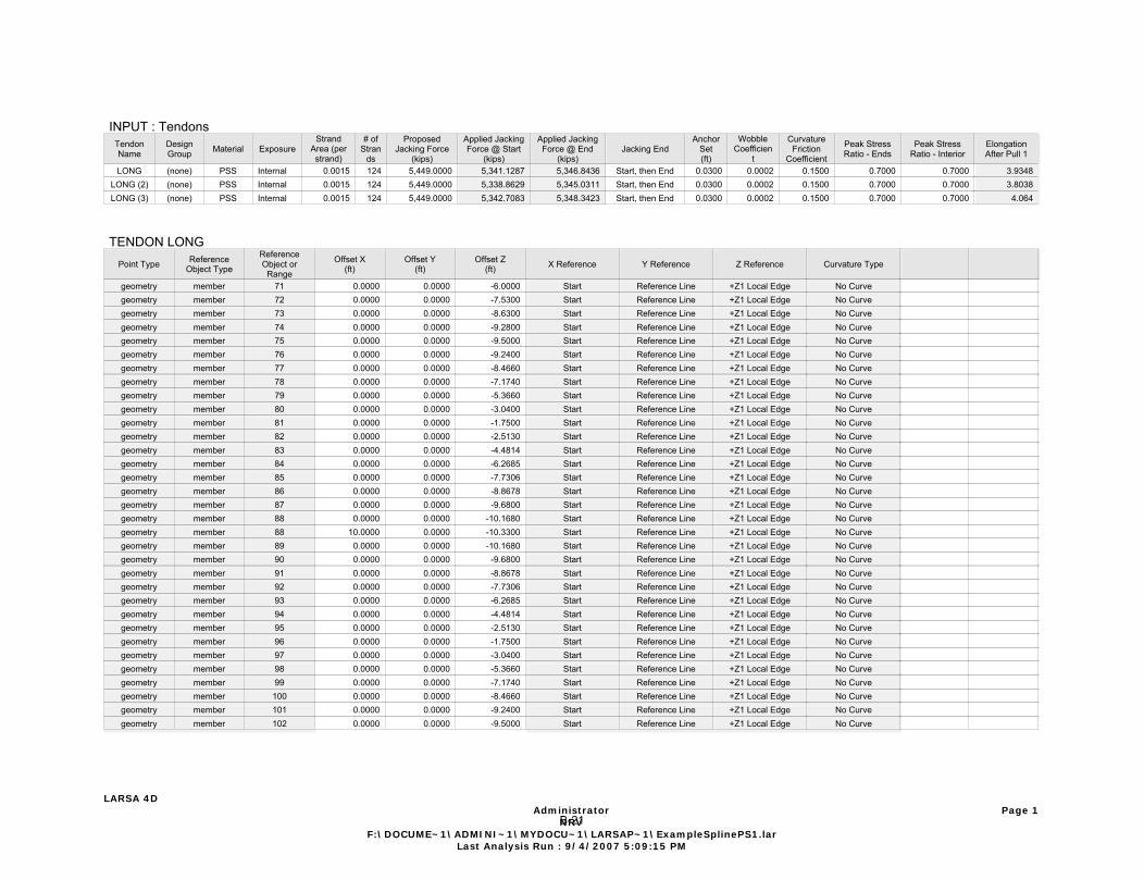
INPUT : TendonsTendonName
DesignGroup Material Exposure
StrandArea (perstrand)
# ofStran
ds
ProposedJacking Force
(kips)
Applied JackingForce @ Start
(kips)
Applied JackingForce @ End
(kips)Jacking End
AnchorSet(ft)
WobbleCoefficien
t
CurvatureFriction
Coefficient
Peak StressRatio - Ends
Peak StressRatio - Interior
ElongationAfter Pull 1
LONG (none) PSS Internal 0.0015 124 5,449.0000 5,341.1287 5,346.8436 Start, then End 0.0300 0.0002 0.1500 0.7000 0.7000 3.9348LONG (2) (none) PSS Internal 0.0015 124 5,449.0000 5,338.8629 5,345.0311 Start, then End 0.0300 0.0002 0.1500 0.7000 0.7000 3.8038LONG (3) (none) PSS Internal 0.0015 124 5,449.0000 5,342.7083 5,348.3423 Start, then End 0.0300 0.0002 0.1500 0.7000 0.7000 4.064
TENDON LONGPoint Type Reference
Object Type
ReferenceObject or
Range
Offset X(ft)
Offset Y(ft)
Offset Z(ft) X Reference Y Reference Z Reference Curvature Type
geometry member 71 0.0000 0.0000 -6.0000 Start Reference Line +Z1 Local Edge No Curvegeometry member 72 0.0000 0.0000 -7.5300 Start Reference Line +Z1 Local Edge No Curvegeometry member 73 0.0000 0.0000 -8.6300 Start Reference Line +Z1 Local Edge No Curvegeometry member 74 0.0000 0.0000 -9.2800 Start Reference Line +Z1 Local Edge No Curvegeometry member 75 0.0000 0.0000 -9.5000 Start Reference Line +Z1 Local Edge No Curvegeometry member 76 0.0000 0.0000 -9.2400 Start Reference Line +Z1 Local Edge No Curvegeometry member 77 0.0000 0.0000 -8.4660 Start Reference Line +Z1 Local Edge No Curvegeometry member 78 0.0000 0.0000 -7.1740 Start Reference Line +Z1 Local Edge No Curvegeometry member 79 0.0000 0.0000 -5.3660 Start Reference Line +Z1 Local Edge No Curvegeometry member 80 0.0000 0.0000 -3.0400 Start Reference Line +Z1 Local Edge No Curvegeometry member 81 0.0000 0.0000 -1.7500 Start Reference Line +Z1 Local Edge No Curvegeometry member 82 0.0000 0.0000 -2.5130 Start Reference Line +Z1 Local Edge No Curvegeometry member 83 0.0000 0.0000 -4.4814 Start Reference Line +Z1 Local Edge No Curvegeometry member 84 0.0000 0.0000 -6.2685 Start Reference Line +Z1 Local Edge No Curvegeometry member 85 0.0000 0.0000 -7.7306 Start Reference Line +Z1 Local Edge No Curvegeometry member 86 0.0000 0.0000 -8.8678 Start Reference Line +Z1 Local Edge No Curvegeometry member 87 0.0000 0.0000 -9.6800 Start Reference Line +Z1 Local Edge No Curvegeometry member 88 0.0000 0.0000 -10.1680 Start Reference Line +Z1 Local Edge No Curvegeometry member 88 10.0000 0.0000 -10.3300 Start Reference Line +Z1 Local Edge No Curvegeometry member 89 0.0000 0.0000 -10.1680 Start Reference Line +Z1 Local Edge No Curvegeometry member 90 0.0000 0.0000 -9.6800 Start Reference Line +Z1 Local Edge No Curvegeometry member 91 0.0000 0.0000 -8.8678 Start Reference Line +Z1 Local Edge No Curvegeometry member 92 0.0000 0.0000 -7.7306 Start Reference Line +Z1 Local Edge No Curvegeometry member 93 0.0000 0.0000 -6.2685 Start Reference Line +Z1 Local Edge No Curvegeometry member 94 0.0000 0.0000 -4.4814 Start Reference Line +Z1 Local Edge No Curvegeometry member 95 0.0000 0.0000 -2.5130 Start Reference Line +Z1 Local Edge No Curvegeometry member 96 0.0000 0.0000 -1.7500 Start Reference Line +Z1 Local Edge No Curvegeometry member 97 0.0000 0.0000 -3.0400 Start Reference Line +Z1 Local Edge No Curvegeometry member 98 0.0000 0.0000 -5.3660 Start Reference Line +Z1 Local Edge No Curvegeometry member 99 0.0000 0.0000 -7.1740 Start Reference Line +Z1 Local Edge No Curvegeometry member 100 0.0000 0.0000 -8.4660 Start Reference Line +Z1 Local Edge No Curvegeometry member 101 0.0000 0.0000 -9.2400 Start Reference Line +Z1 Local Edge No Curvegeometry member 102 0.0000 0.0000 -9.5000 Start Reference Line +Z1 Local Edge No Curve
LARSA 4D Administrator
NRVF:\DOCUME~1\ADMINI~1\MYDOCU~1\LARSAP~1\ExampleSplinePS1.lar
Last Analysis Run : 9/4/2007 5:09:15 PM
Page 1B-21

TENDON LONGPoint Type Reference
Object Type
ReferenceObject or
Range
Offset X(ft)
Offset Y(ft)
Offset Z(ft) X Reference Y Reference Z Reference Curvature Type
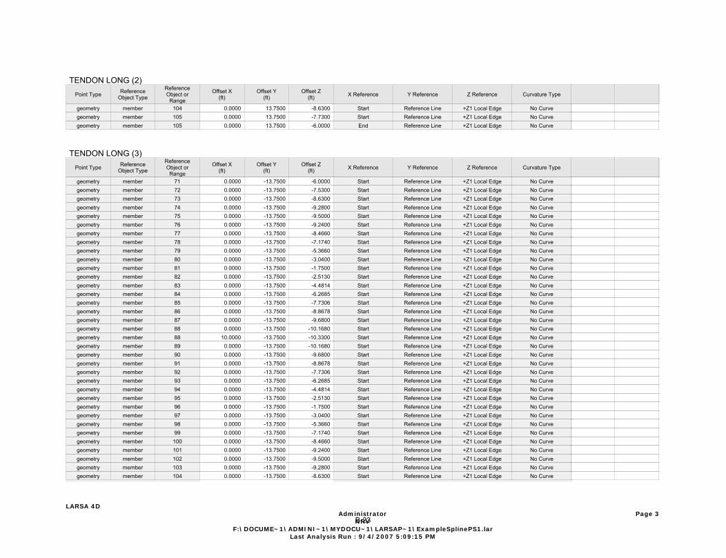
geometry member 103 0.0000 0.0000 -9.2800 Start Reference Line +Z1 Local Edge No Curvegeometry member 104 0.0000 0.0000 -8.6300 Start Reference Line +Z1 Local Edge No Curvegeometry member 105 0.0000 0.0000 -7.7300 Start Reference Line +Z1 Local Edge No Curvegeometry member 105 0.0000 0.0000 -6.0000 End Reference Line +Z1 Local Edge No Curve
TENDON LONG (2)Point Type Reference
Object Type
ReferenceObject or
Range
Offset X(ft)
Offset Y(ft)
Offset Z(ft) X Reference Y Reference Z Reference Curvature Type
geometry member 71 0.0000 13.7500 -6.0000 Start Reference Line +Z1 Local Edge No Curvegeometry member 72 0.0000 13.7500 -7.5300 Start Reference Line +Z1 Local Edge No Curvegeometry member 73 0.0000 13.7500 -8.6300 Start Reference Line +Z1 Local Edge No Curvegeometry member 74 0.0000 13.7500 -9.2800 Start Reference Line +Z1 Local Edge No Curvegeometry member 75 0.0000 13.7500 -9.5000 Start Reference Line +Z1 Local Edge No Curvegeometry member 76 0.0000 13.7500 -9.2400 Start Reference Line +Z1 Local Edge No Curvegeometry member 77 0.0000 13.7500 -8.4660 Start Reference Line +Z1 Local Edge No Curvegeometry member 78 0.0000 13.7500 -7.1740 Start Reference Line +Z1 Local Edge No Curvegeometry member 79 0.0000 13.7500 -5.3660 Start Reference Line +Z1 Local Edge No Curvegeometry member 80 0.0000 13.7500 -3.0400 Start Reference Line +Z1 Local Edge No Curvegeometry member 81 0.0000 13.7500 -1.7500 Start Reference Line +Z1 Local Edge No Curvegeometry member 82 0.0000 13.7500 -2.5130 Start Reference Line +Z1 Local Edge No Curvegeometry member 83 0.0000 13.7500 -4.4814 Start Reference Line +Z1 Local Edge No Curvegeometry member 84 0.0000 13.7500 -6.2685 Start Reference Line +Z1 Local Edge No Curvegeometry member 85 0.0000 13.7500 -7.7306 Start Reference Line +Z1 Local Edge No Curvegeometry member 86 0.0000 13.7500 -8.8678 Start Reference Line +Z1 Local Edge No Curvegeometry member 87 0.0000 13.7500 -9.6800 Start Reference Line +Z1 Local Edge No Curvegeometry member 88 0.0000 13.7500 -10.1680 Start Reference Line +Z1 Local Edge No Curvegeometry member 88 10.0000 13.7500 -10.3300 Start Reference Line +Z1 Local Edge No Curvegeometry member 89 0.0000 13.7500 -10.1680 Start Reference Line +Z1 Local Edge No Curvegeometry member 90 0.0000 13.7500 -9.6800 Start Reference Line +Z1 Local Edge No Curvegeometry member 91 0.0000 13.7500 -8.8678 Start Reference Line +Z1 Local Edge No Curvegeometry member 92 0.0000 13.7500 -7.7306 Start Reference Line +Z1 Local Edge No Curvegeometry member 93 0.0000 13.7500 -6.2685 Start Reference Line +Z1 Local Edge No Curvegeometry member 94 0.0000 13.7500 -4.4814 Start Reference Line +Z1 Local Edge No Curvegeometry member 95 0.0000 13.7500 -2.5130 Start Reference Line +Z1 Local Edge No Curvegeometry member 96 0.0000 13.7500 -1.7500 Start Reference Line +Z1 Local Edge No Curvegeometry member 97 0.0000 13.7500 -3.0400 Start Reference Line +Z1 Local Edge No Curvegeometry member 98 0.0000 13.7500 -5.3660 Start Reference Line +Z1 Local Edge No Curvegeometry member 99 0.0000 13.7500 -7.1740 Start Reference Line +Z1 Local Edge No Curvegeometry member 100 0.0000 13.7500 -8.4660 Start Reference Line +Z1 Local Edge No Curvegeometry member 101 0.0000 13.7500 -9.2400 Start Reference Line +Z1 Local Edge No Curvegeometry member 102 0.0000 13.7500 -9.5000 Start Reference Line +Z1 Local Edge No Curvegeometry member 103 0.0000 13.7500 -9.2800 Start Reference Line +Z1 Local Edge No Curve
LARSA 4D Administrator
NRVF:\DOCUME~1\ADMINI~1\MYDOCU~1\LARSAP~1\ExampleSplinePS1.lar
Last Analysis Run : 9/4/2007 5:09:15 PM
Page 2B-22
TENDON LONG (2)Point Type Reference
Object Type
ReferenceObject or
Range
Offset X(ft)
Offset Y(ft)
Offset Z(ft) X Reference Y Reference Z Reference Curvature Type
geometry member 104 0.0000 13.7500 -8.6300 Start Reference Line +Z1 Local Edge No Curvegeometry member 105 0.0000 13.7500 -7.7300 Start Reference Line +Z1 Local Edge No Curvegeometry member 105 0.0000 13.7500 -6.0000 End Reference Line +Z1 Local Edge No Curve
TENDON LONG (3)Point Type Reference
Object Type
ReferenceObject or
Range
Offset X(ft)
Offset Y(ft)
Offset Z(ft) X Reference Y Reference Z Reference Curvature Type
geometry member 71 0.0000 -13.7500 -6.0000 Start Reference Line +Z1 Local Edge No Curvegeometry member 72 0.0000 -13.7500 -7.5300 Start Reference Line +Z1 Local Edge No Curvegeometry member 73 0.0000 -13.7500 -8.6300 Start Reference Line +Z1 Local Edge No Curvegeometry member 74 0.0000 -13.7500 -9.2800 Start Reference Line +Z1 Local Edge No Curvegeometry member 75 0.0000 -13.7500 -9.5000 Start Reference Line +Z1 Local Edge No Curvegeometry member 76 0.0000 -13.7500 -9.2400 Start Reference Line +Z1 Local Edge No Curvegeometry member 77 0.0000 -13.7500 -8.4660 Start Reference Line +Z1 Local Edge No Curvegeometry member 78 0.0000 -13.7500 -7.1740 Start Reference Line +Z1 Local Edge No Curvegeometry member 79 0.0000 -13.7500 -5.3660 Start Reference Line +Z1 Local Edge No Curvegeometry member 80 0.0000 -13.7500 -3.0400 Start Reference Line +Z1 Local Edge No Curvegeometry member 81 0.0000 -13.7500 -1.7500 Start Reference Line +Z1 Local Edge No Curvegeometry member 82 0.0000 -13.7500 -2.5130 Start Reference Line +Z1 Local Edge No Curvegeometry member 83 0.0000 -13.7500 -4.4814 Start Reference Line +Z1 Local Edge No Curvegeometry member 84 0.0000 -13.7500 -6.2685 Start Reference Line +Z1 Local Edge No Curvegeometry member 85 0.0000 -13.7500 -7.7306 Start Reference Line +Z1 Local Edge No Curvegeometry member 86 0.0000 -13.7500 -8.8678 Start Reference Line +Z1 Local Edge No Curvegeometry member 87 0.0000 -13.7500 -9.6800 Start Reference Line +Z1 Local Edge No Curvegeometry member 88 0.0000 -13.7500 -10.1680 Start Reference Line +Z1 Local Edge No Curvegeometry member 88 10.0000 -13.7500 -10.3300 Start Reference Line +Z1 Local Edge No Curvegeometry member 89 0.0000 -13.7500 -10.1680 Start Reference Line +Z1 Local Edge No Curvegeometry member 90 0.0000 -13.7500 -9.6800 Start Reference Line +Z1 Local Edge No Curvegeometry member 91 0.0000 -13.7500 -8.8678 Start Reference Line +Z1 Local Edge No Curvegeometry member 92 0.0000 -13.7500 -7.7306 Start Reference Line +Z1 Local Edge No Curvegeometry member 93 0.0000 -13.7500 -6.2685 Start Reference Line +Z1 Local Edge No Curvegeometry member 94 0.0000 -13.7500 -4.4814 Start Reference Line +Z1 Local Edge No Curvegeometry member 95 0.0000 -13.7500 -2.5130 Start Reference Line +Z1 Local Edge No Curvegeometry member 96 0.0000 -13.7500 -1.7500 Start Reference Line +Z1 Local Edge No Curvegeometry member 97 0.0000 -13.7500 -3.0400 Start Reference Line +Z1 Local Edge No Curvegeometry member 98 0.0000 -13.7500 -5.3660 Start Reference Line +Z1 Local Edge No Curvegeometry member 99 0.0000 -13.7500 -7.1740 Start Reference Line +Z1 Local Edge No Curvegeometry member 100 0.0000 -13.7500 -8.4660 Start Reference Line +Z1 Local Edge No Curvegeometry member 101 0.0000 -13.7500 -9.2400 Start Reference Line +Z1 Local Edge No Curvegeometry member 102 0.0000 -13.7500 -9.5000 Start Reference Line +Z1 Local Edge No Curvegeometry member 103 0.0000 -13.7500 -9.2800 Start Reference Line +Z1 Local Edge No Curvegeometry member 104 0.0000 -13.7500 -8.6300 Start Reference Line +Z1 Local Edge No Curve
LARSA 4D Administrator
NRVF:\DOCUME~1\ADMINI~1\MYDOCU~1\LARSAP~1\ExampleSplinePS1.lar
Last Analysis Run : 9/4/2007 5:09:15 PM
Page 3B-23
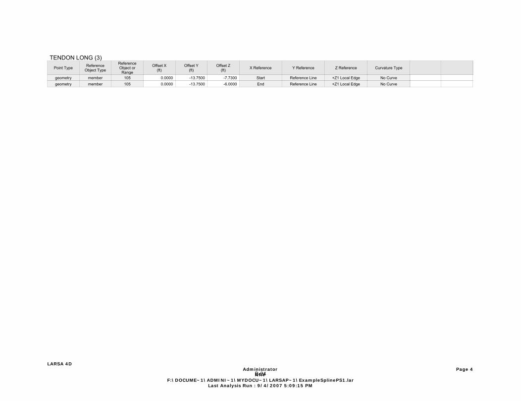
TENDON LONG (3)Point Type Reference
Object Type
ReferenceObject or
Range
Offset X(ft)
Offset Y(ft)
Offset Z(ft) X Reference Y Reference Z Reference Curvature Type
geometry member 105 0.0000 -13.7500 -7.7300 Start Reference Line +Z1 Local Edge No Curvegeometry member 105 0.0000 -13.7500 -6.0000 End Reference Line +Z1 Local Edge No Curve
LARSA 4D Administrator
NRVF:\DOCUME~1\ADMINI~1\MYDOCU~1\LARSAP~1\ExampleSplinePS1.lar
Last Analysis Run : 9/4/2007 5:09:15 PM
Page 4B-24
3400.80
3500.80
3600.80
3700.80
3800.80
3900.80
4000.80
4100.80
4200.80
4300.80
4400.80
4500.80
4600.80
4700.80
4800.80
4900.80
5000.80
5100.80
5200.80
5300.80
0 20 40 60 80 100 120 140 160 180 200 220 240 260 280 300 320 340 360 380 400 420 440 460 480 500 520 540 560 580 600 620 640 660 680 700
Forc
e (k
ips)
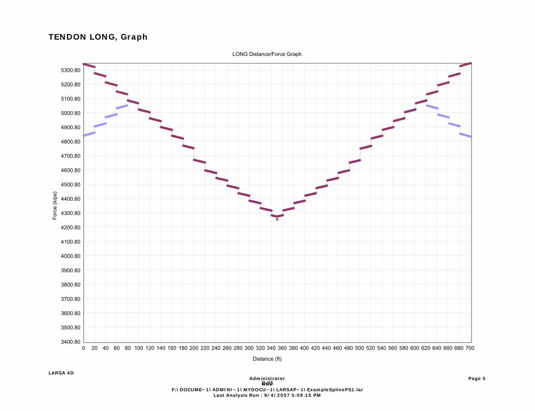
LONG Distance/Force GraphLONG Distance/Force Graph
Distance (ft)
TENDON LONG, Graph
LARSA 4D Administrator
NRVF:\DOCUME~1\ADMINI~1\MYDOCU~1\LARSAP~1\ExampleSplinePS1.lar
Last Analysis Run : 9/4/2007 5:09:15 PM
Page 5B-25
3403.56
3503.56
3603.56
3703.56
3803.56
3903.56
4003.56
4103.56
4203.56
4303.56
4403.56
4503.56
4603.56
4703.56
4803.56
4903.56
5003.56
5103.56
5203.56
5303.56
0 20 40 60 80 100 120 140 160 180 200 220 240 260 280 300 320 340 360 380 400 420 440 460 480 500 520 540 560 580 600 620 640 660
Forc
e (k
ips)
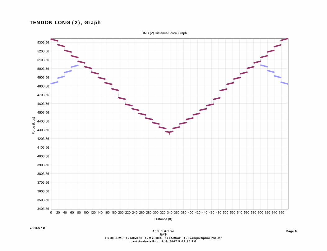
LONG (2) Distance/Force GraphLONG (2) Distance/Force Graph
Distance (ft)
TENDON LONG (2), Graph
LARSA 4D Administrator
NRVF:\DOCUME~1\ADMINI~1\MYDOCU~1\LARSAP~1\ExampleSplinePS1.lar
Last Analysis Run : 9/4/2007 5:09:15 PM
Page 6B-26
3396.11
3496.11
3596.11
3696.11
3796.11
3896.11
3996.11
4096.11
4196.11
4296.11
4396.11
4496.11
4596.11
4696.11
4796.11
4896.11
4996.11
5096.11
5196.11
5296.11
0 20 40 60 80 100 120 140 160 180 200 220 240 260 280 300 320 340 360 380 400 420 440 460 480 500 520 540 560 580 600 620 640 660 680 700 720
Forc
e (k
ips)
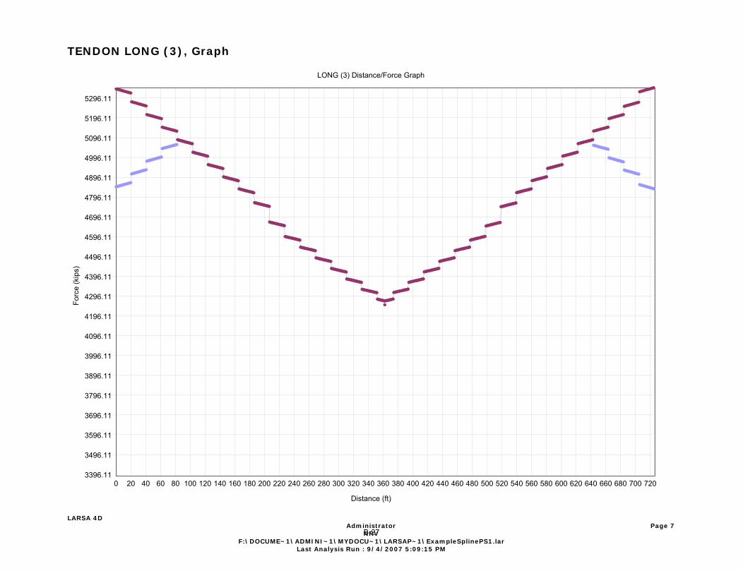
LONG (3) Distance/Force GraphLONG (3) Distance/Force Graph
Distance (ft)
TENDON LONG (3), Graph
LARSA 4D Administrator
NRVF:\DOCUME~1\ADMINI~1\MYDOCU~1\LARSAP~1\ExampleSplinePS1.lar
Last Analysis Run : 9/4/2007 5:09:15 PM
Page 7B-27
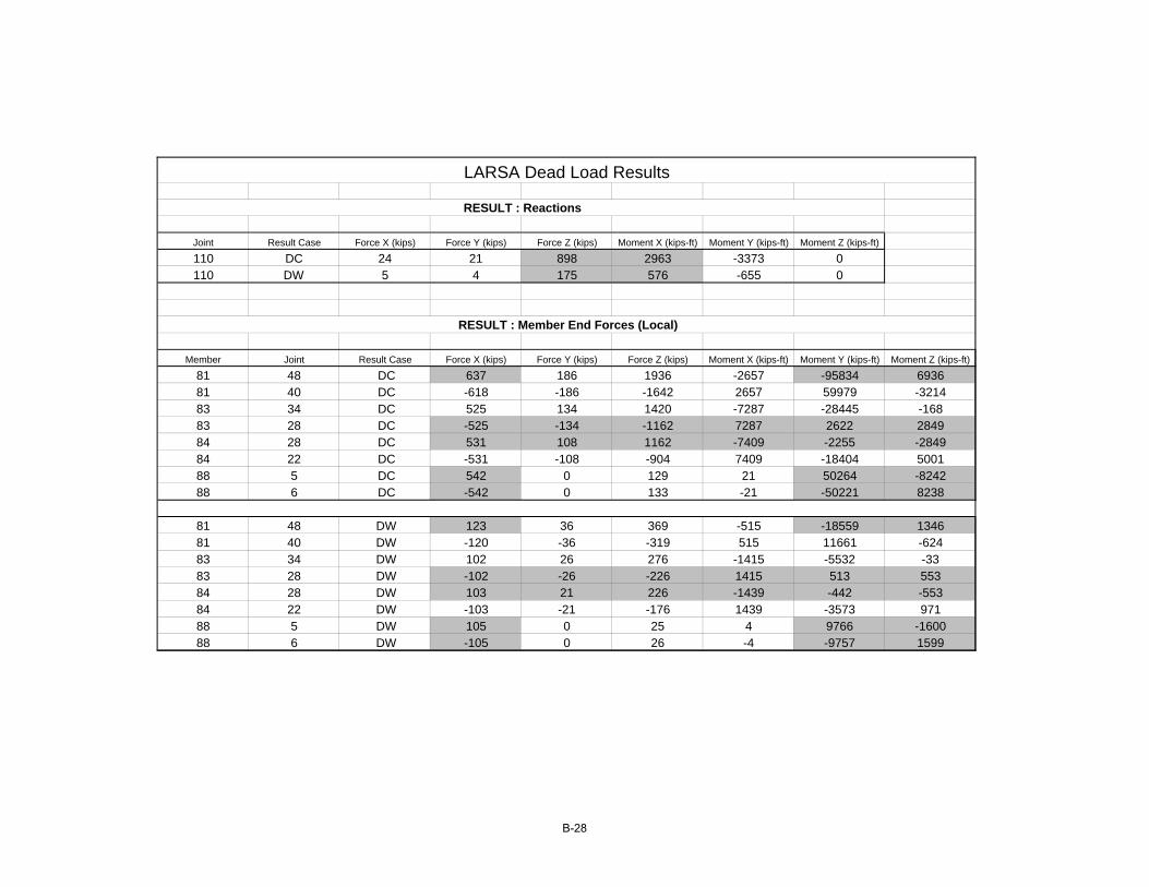
Joint Result Case Force X (kips) Force Y (kips) Force Z (kips) Moment X (kips-ft) Moment Y (kips-ft) Moment Z (kips-ft)
110 DC 24 21 898 2963 -3373 0110 DW 5 4 175 576 -655 0
Member Joint Result Case Force X (kips) Force Y (kips) Force Z (kips) Moment X (kips-ft) Moment Y (kips-ft) Moment Z (kips-ft)
81 48 DC 637 186 1936 -2657 -95834 693681 40 DC -618 -186 -1642 2657 59979 -321483 34 DC 525 134 1420 -7287 -28445 -16883 28 DC -525 -134 -1162 7287 2622 284984 28 DC 531 108 1162 -7409 -2255 -284984 22 DC -531 -108 -904 7409 -18404 500188 5 DC 542 0 129 21 50264 -824288 6 DC -542 0 133 -21 -50221 8238
81 48 DW 123 36 369 -515 -18559 134681 40 DW -120 -36 -319 515 11661 -62483 34 DW 102 26 276 -1415 -5532 -3383 28 DW -102 -26 -226 1415 513 55384 28 DW 103 21 226 -1439 -442 -55384 22 DW -103 -21 -176 1439 -3573 97188 5 DW 105 0 25 4 9766 -160088 6 DW -105 0 26 -4 -9757 1599
RESULT : Reactions
RESULT : Member End Forces (Local)
LARSA Dead Load Results
B-28
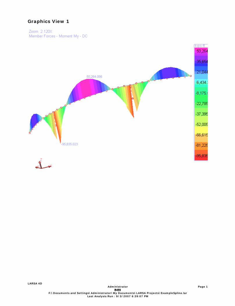
Graphics View 1
LARSA 4D Administrator
NRVF:\Documents and Settings\Administrator\My Documents\LARSA Projects\ExampleSpline.lar
Last Analysis Run : 9/3/2007 6:39:07 PM
Page 1
B-29

Graphics View 1
LARSA 4D Administrator
NRVF:\Documents and Settings\Administrator\My Documents\LARSA Projects\ExampleSpline.lar
Last Analysis Run : 9/3/2007 6:39:07 PM
Page 1
B-30

Graphics View 1
LARSA 4D Administrator
NRVF:\Documents and Settings\Administrator\My Documents\LARSA Projects\ExampleSpline.lar
Last Analysis Run : 9/3/2007 6:39:07 PM
Page 1
B-31
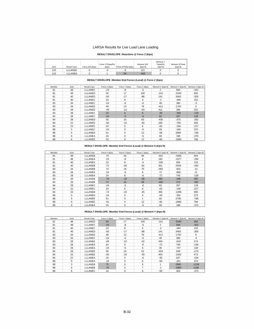
Joint Result Case Force X/R (kips)Force Y/Theta/Phi
(kips) Force Z/Theta (kips)Moment X/R
(kips-ft)
Moment YTheta/Phi (kips-ft)
Moment Z/Theta (kips-ft)
110 LLLANEE 0 -3 -9 121 0 0110 LLLANEA 0 1 54 -343 0 0
Member Joint Result Case Force X (kips) Force Y (kips) Force Z (kips) Moment X (kips-ft) Moment Y (kips-ft) Moment Z (kips-ft)
81 48 LLLANEC -23 -8 -5 2 594 -32281 48 LLLANED 50 17 100 -141 -5343 65581 40 LLLANED -50 -17 -88 141 3463 -30581 40 LLLANEC 23 8 5 -2 -494 15283 34 LLLANEC -24 -6 -6 49 380 -583 34 LLLANED 49 13 76 -411 -1787 083 28 LLLANED -49 -13 -63 411 396 25283 28 LLLANEC 24 6 6 -49 -269 -11884 28 LLLANEC -24 -5 -6 63 267 11884 28 LLLANED 50 10 63 -430 -375 -25284 22 LLLANED -50 -10 -50 430 -759 45684 22 LLLANEC 24 5 6 -63 -156 -21788 5 LLLANEC -24 0 -6 59 -190 37088 5 LLLANED 51 0 12 -58 2684 -76688 6 LLLANEA 24 0 -6 59 188 -37088 6 LLLANEE -51 0 12 -60 -2680 766
Member Joint Result Case Force X (kips) Force Y (kips) Force Z (kips) Moment X (kips-ft) Moment Y (kips-ft) Moment Z (kips-ft)
81 48 LLLANEB 73 26 94 -301 -4266 94481 48 LLLANEA -23 -8 6 160 -1077 -29081 40 LLLANEA 23 8 -6 -160 955 12581 40 LLLANEB -72 -26 -81 301 2509 -43083 34 LLLANEB 73 19 70 -483 -931 -2183 34 LLLANEA -24 -6 6 72 -856 2183 28 LLLANEA 24 6 -6 -72 745 -13983 28 LLLANEB -73 -19 -58 483 -348 39284 28 LLLANEB 74 15 58 -465 372 -39284 28 LLLANEC -24 -5 -6 63 267 11884 22 LLLANEC 24 5 6 -63 -156 -21784 22 LLLANEB -74 -15 -45 465 -1396 69088 5 LLLANEA -24 0 6 -59 -301 37388 5 LLLANEE 51 0 1 60 2795 -76888 6 LLLANEE -51 0 12 -60 -2680 76688 6 LLLANEA 24 0 -6 59 188 -370
Member Joint Result Case Force X (kips) Force Y (kips) Force Z (kips) Moment X (kips-ft) Moment Y (kips-ft) Moment Z (kips-ft)
81 48 LLLANED 50 17 100 -141 -5343 65581 48 LLLANEC -23 -8 -5 2 594 -32281 40 LLLANEC 23 8 5 -2 -494 15281 40 LLLANED -50 -17 -88 141 3463 -30583 34 LLLANED 49 13 76 -411 -1787 083 34 LLLANEC -24 -6 -6 49 380 -583 28 LLLANEE -49 -12 -52 434 -618 27483 28 LLLANEA 24 6 -6 -72 745 -13984 28 LLLANEA -24 -5 6 35 -747 13984 28 LLLANEE 50 10 52 -403 639 -27484 22 LLLANEE -50 -10 -39 403 -1552 47384 22 LLLANEA 24 5 -6 -35 637 -23488 5 LLLANEA -24 0 6 -59 -301 37388 5 LLLANEB 75 0 6 1 2985 -113988 6 LLLANEB -75 0 7 -1 -2983 113888 6 LLLANEC 24 0 6 -59 303 -373
RESULT ENVELOPE :Member End Forces (Local) @ Moment Y (kips-ft)
LARSA Results for Live Load Lane Loading
RESULT ENVELOPE :Reactions @ Force Z (kips)
RESULT ENVELOPE :Member End Forces (Local) @ Force Z (kips)
RESULT ENVELOPE :Member End Forces (Local) @ Moment X (kips-ft)
B-32
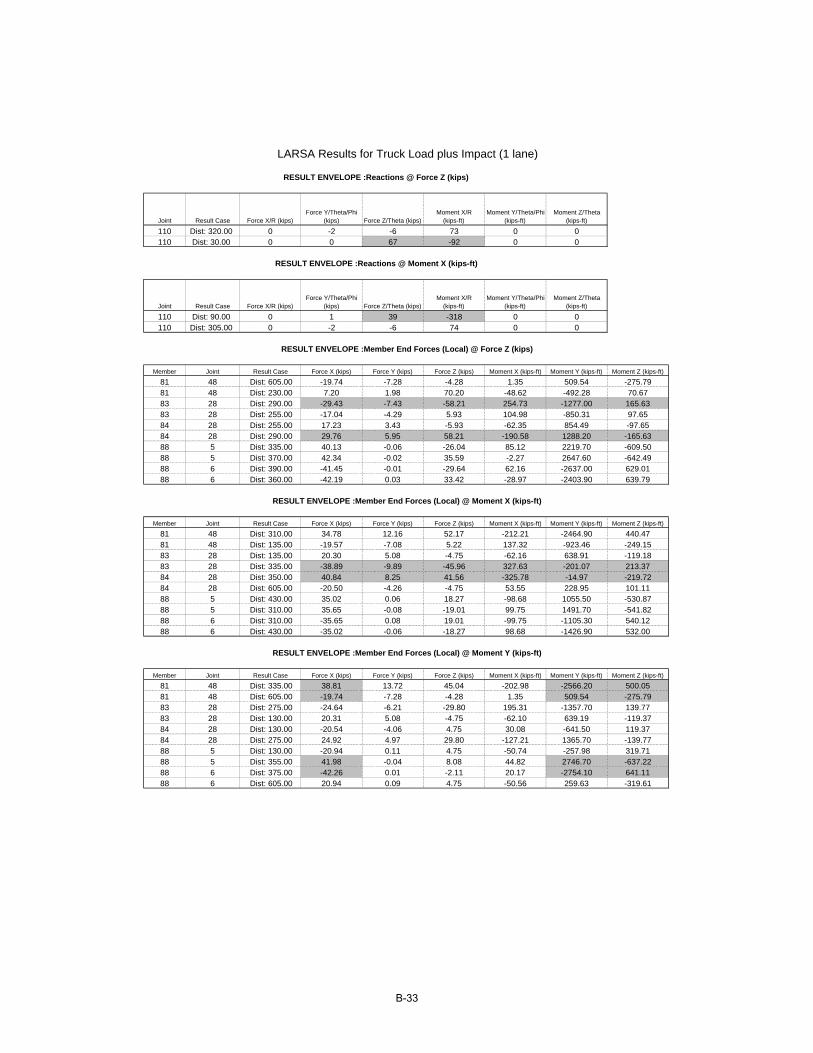
Joint Result Case Force X/R (kips)Force Y/Theta/Phi
(kips) Force Z/Theta (kips)Moment X/R
(kips-ft)Moment Y/Theta/Phi
(kips-ft)Moment Z/Theta
(kips-ft)
110 Dist: 320.00 0 -2 -6 73 0 0110 Dist: 30.00 0 0 67 -92 0 0
Joint Result Case Force X/R (kips)Force Y/Theta/Phi
(kips) Force Z/Theta (kips)Moment X/R
(kips-ft)Moment Y/Theta/Phi
(kips-ft)Moment Z/Theta
(kips-ft)
110 Dist: 90.00 0 1 39 -318 0 0110 Dist: 305.00 0 -2 -6 74 0 0
Member Joint Result Case Force X (kips) Force Y (kips) Force Z (kips) Moment X (kips-ft) Moment Y (kips-ft) Moment Z (kips-ft)
81 48 Dist: 605.00 -19.74 -7.28 -4.28 1.35 509.54 -275.7981 48 Dist: 230.00 7.20 1.98 70.20 -48.62 -492.28 70.6783 28 Dist: 290.00 -29.43 -7.43 -58.21 254.73 -1277.00 165.6383 28 Dist: 255.00 -17.04 -4.29 5.93 104.98 -850.31 97.6584 28 Dist: 255.00 17.23 3.43 -5.93 -62.35 854.49 -97.6584 28 Dist: 290.00 29.76 5.95 58.21 -190.58 1288.20 -165.6388 5 Dist: 335.00 40.13 -0.06 -26.04 85.12 2219.70 -609.5088 5 Dist: 370.00 42.34 -0.02 35.59 -2.27 2647.60 -642.4988 6 Dist: 390.00 -41.45 -0.01 -29.64 62.16 -2637.00 629.0188 6 Dist: 360.00 -42.19 0.03 33.42 -28.97 -2403.90 639.79
Member Joint Result Case Force X (kips) Force Y (kips) Force Z (kips) Moment X (kips-ft) Moment Y (kips-ft) Moment Z (kips-ft)
81 48 Dist: 310.00 34.78 12.16 52.17 -212.21 -2464.90 440.4781 48 Dist: 135.00 -19.57 -7.08 5.22 137.32 -923.46 -249.1583 28 Dist: 135.00 20.30 5.08 -4.75 -62.16 638.91 -119.1883 28 Dist: 335.00 -38.89 -9.89 -45.96 327.63 -201.07 213.3784 28 Dist: 350.00 40.84 8.25 41.56 -325.78 -14.97 -219.7284 28 Dist: 605.00 -20.50 -4.26 -4.75 53.55 228.95 101.1188 5 Dist: 430.00 35.02 0.06 18.27 -98.68 1055.50 -530.8788 5 Dist: 310.00 35.65 -0.08 -19.01 99.75 1491.70 -541.8288 6 Dist: 310.00 -35.65 0.08 19.01 -99.75 -1105.30 540.1288 6 Dist: 430.00 -35.02 -0.06 -18.27 98.68 -1426.90 532.00
Member Joint Result Case Force X (kips) Force Y (kips) Force Z (kips) Moment X (kips-ft) Moment Y (kips-ft) Moment Z (kips-ft)
81 48 Dist: 335.00 38.81 13.72 45.04 -202.98 -2566.20 500.0581 48 Dist: 605.00 -19.74 -7.28 -4.28 1.35 509.54 -275.7983 28 Dist: 275.00 -24.64 -6.21 -29.80 195.31 -1357.70 139.7783 28 Dist: 130.00 20.31 5.08 -4.75 -62.10 639.19 -119.3784 28 Dist: 130.00 -20.54 -4.06 4.75 30.08 -641.50 119.3784 28 Dist: 275.00 24.92 4.97 29.80 -127.21 1365.70 -139.7788 5 Dist: 130.00 -20.94 0.11 4.75 -50.74 -257.98 319.7188 5 Dist: 355.00 41.98 -0.04 8.08 44.82 2746.70 -637.2288 6 Dist: 375.00 -42.26 0.01 -2.11 20.17 -2754.10 641.1188 6 Dist: 605.00 20.94 0.09 4.75 -50.56 259.63 -319.61
RESULT ENVELOPE :Member End Forces (Local) @ Moment Y (kips-ft)
LARSA Results for Truck Load plus Impact (1 lane)
RESULT ENVELOPE :Reactions @ Force Z (kips)
RESULT ENVELOPE :Reactions @ Moment X (kips-ft)
RESULT ENVELOPE :Member End Forces (Local) @ Force Z (kips)
RESULT ENVELOPE :Member End Forces (Local) @ Moment X (kips-ft)
B-33

Joint Result Case Force X/R (kips) Force Y/Theta/Phi (kips) Force Z/Theta (kips) Moment X/R
(kips-ft)
Moment Y/Theta/Phi
(kips-ft)
Moment Z/Theta (kips-ft)
110 Final Prestress 0 35 85 -1748 0 0
Member Joint Result Case Force X (kips) Force Y (kips) Force Z (kips) Moment X (kips-ft) Moment Y (kips-ft) Moment Z (kips-ft)
81 48 Final Prestress 12550 -584 -876 -16453 88026 -871183 28 Final Prestress -11866 -172 1009 6673 -12476 -823784 28 Final Prestress 11860 -422 -1009 -6041 12794 823788 5 Final Prestress 11267 -206 -229 -673 -33644 1865388 6 Final Prestress -11256 -206 -230 -1730 33550 -18253
Member Location Stage Fx (kips) Fy (kips) Fz (kips) Primary Mx (kips-ft)
Primary My (kips-ft)
Primary Mz (kips-ft)
81 Start Final Prestress 13523 246 -746 2523 58644 68881 End Final Prestress 13189 406 -1837 -3939 30529 54983 Start Final Prestress 13016 346 -1165 -453 4334 36283 End Final Prestress 12887 343 -944 222 -18709 32284 Start Final Prestress 12887 343 -944 222 -18709 32284 End Final Prestress 12755 127 -726 156 -37139 28888 Start Final Prestress 12310 330 -200 1764 -65773 21888 End Final Prestress 12315 124 306 759 -65730 13
RESULT : Reactions
RESULT : Member End Forces (Local)
LARSA Results for Final Prestress
RESULT : Total Tendon Forces @ Member Ends
B-34
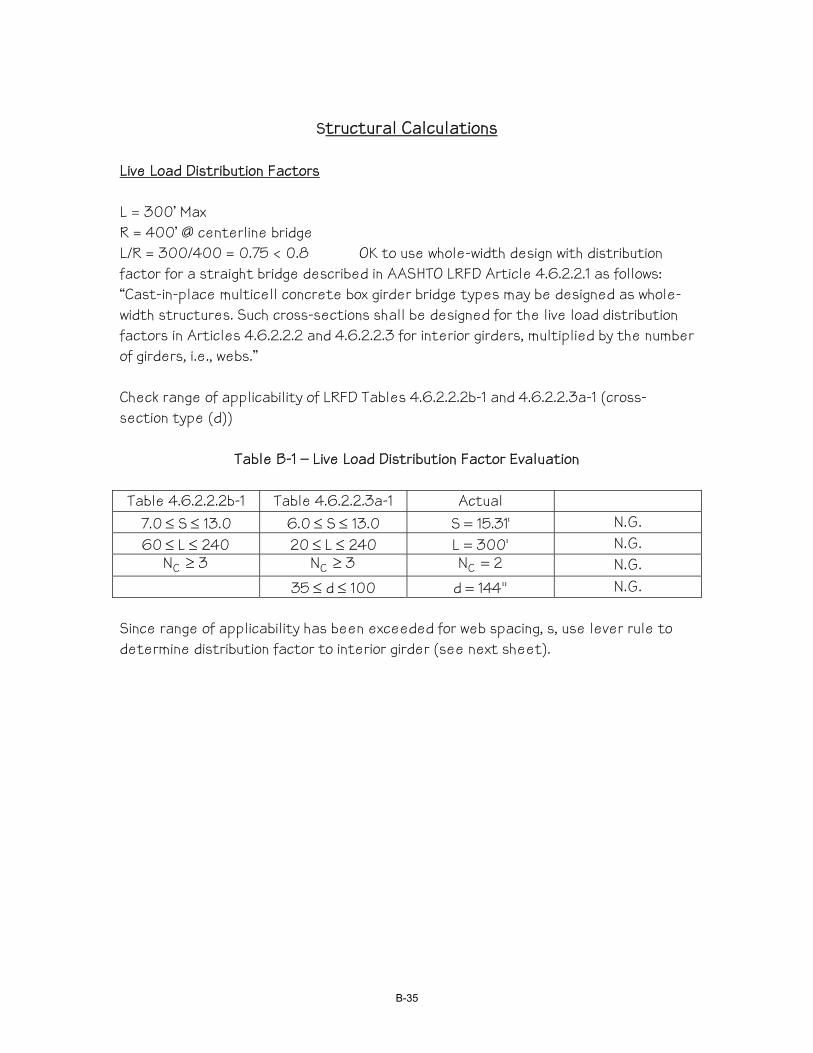
Structural Calculations
Live Load Distribution Factors L = 300’ Max R = 400’ @ centerline bridge L/R = 300/400 = 0.75 < 0.8 OK to use whole-width design with distribution factor for a straight bridge described in AASHTO LRFD Article 4.6.2.2.1 as follows: “Cast-in-place multicell concrete box girder bridge types may be designed as whole-width structures. Such cross-sections shall be designed for the live load distribution factors in Articles 4.6.2.2.2 and 4.6.2.2.3 for interior girders, multiplied by the number of girders, i.e., webs.” Check range of applicability of LRFD Tables 4.6.2.2.2b-1 and 4.6.2.2.3a-1 (cross-section type (d))
Table B-1 – Live Load Distribution Factor Evaluation
Table 4.6.2.2.2b-1 Table 4.6.2.2.3a-1 Actual 0.13S0.7 ≤≤ 0.13S0.6 ≤≤ '31.15S = N.G.
240L60 ≤≤ 240L20 ≤≤ '300L = N.G. 3NC ≥ 3NC ≥ 2NC = N.G.
100d35 ≤≤ "144d = N.G. Since range of applicability has been exceeded for web spacing, s, use lever rule to determine distribution factor to interior girder (see next sheet).
B-35
Interior Girder – Live Load Distribution Factor
Figure B-10 – Live Load Lane Positions
Case 1: 1.0(9.31+15.31+5.31+11.31)/(2x15.31) = 1.347 Case 2: 1.0(7.31+13.31)x2/(2x15.31) = 1.347 Case 3: 0.85(0.31+6.31+12.31)x2/(2x15.31) = 1.051 Maximum Distribution Factor = df(max) =1.347
B-36
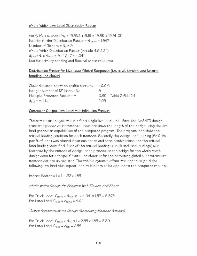
Whole Width Live Load Distribution Factor Verify We < s, where We = 15.31/2 + 6.19 = 13.85 < 15.31 OK Interior Girder Distribution Factor = df(max) = 1.347 Number of Girders = NL = 3 Whole Width Distribution Factor (Article 4.6.2.2.1) df(ww)=NL x df(max)= 3 x 1.347 = 4.041 Use for primary bending and flexural shear response Distribution Factor for Live Load Global Response (i.e. axial, torsion, and lateral bending and shear) Clear distance between traffic barriers: 40.0 ft Integer number of 12’ lanes - NL: 3 Multiple Presence factor – m 0.85 Table 3.6.1.1.2-1 df(t) = m x NL: 2.55 Computer Output Live Load Multiplication Factors The computer analysis was run for a single live load lane. First the AASHTO design truck was placed at incremental locations down the length of the bridge using the live load generator capabilities of the computer program. The program identified the critical loading condition for each member. Secondly the design lane loading (640 lbs per ft of lane) was placed in various spans and span combinations and the critical lane loading identified. Each of the critical loadings (truck and lane loadings) was factored by the number of design lanes present on the bridge for the whole-width design case for principal flexure and shear or for the remaining global superstructure member actions as required. The vehicle dynamic effect was added to yield the following live load plus impact load multipliers to be applied to the computer results. Impact Factor = I = 1 + .33= 1.33 Whole-Width Design for Principal Web Flexure and Shear For Truck Load: Ctruck = df(ww) x I = 4.041 x 1.33 = 5.375 For Lane Load: Clane = df(ww) = 4.041 Global Superstructure Design (Remaining Member Actions) For Truck Load: Ctruck = df(t) x I = 2.55 x 1.33 = 3.39 For Lane Load: Clane = df(t) = 2.55
B-37

B-38
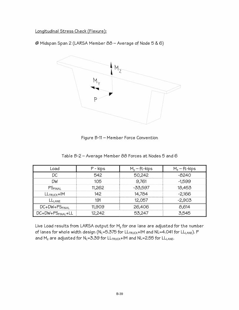
Longitudinal Stress Check (Flexure): @ Midspan Span 2 (LARSA Member 88 – Average of Node 5 & 6)
Figure B-11 – Member Force Convention
Table B-2 – Average Member 88 Forces at Nodes 5 and 6
Load P - kips My – ft-kips Mz – ft-kips DC 542 50,242 -8240 DW 105 9,761 -1,599
PSFINAL 11,262 -33,597 18,453 LLTRUCK+IM 142 14,784 -2,166
LLLANE 191 12,057 -2,903 DC+DW+PSFINAL 11,909 26,406 8,614
DC+DW+PSFINAL+LL 12,242 53,247 3,545 Live Load results from LARSA output for My for one lane are adjusted for the number of lanes for whole width design (NL=5.375 for LLTRUCK+IM and NL=4.041 for LLLANE). P and Mz are adjusted for NL=3.39 for LLTRUCK+IM and NL=2.55 for LLLANE.
B-39

Stress Distribution at Midspan of Span 2 (from STAAD Section Wizard):
2.24e+2
2.917e+1
Figure B-12 - Stress Distribution at Midspan of Span 2 (ksf)
DC+DW+PSFINAL Red = Compression (224 ksf ⇒ 1556 psi max)
Blue = Tension (None – in compression)
2.813e+2
-5.803e+1
Figure B-13 - Stress Distribution at Midspan of Span 2 (ksf)
DC+DW+PSFINAL+LL+IM Red = Compression (281.3 ksf ⇒ 1953 psi max)
Blue = Tension (58.03 ksf ⇒ 403 psi max)
B-40

@ Bent 3 - Span 2 (LARSA Member 81 –Node 48)
Table B-3 –Member 81 Forces at Node 48
Load P - kips My – ft-kips Mz – ft-kips DC 637 -95,834 6,936 DW 123 -18,559 1,346
PSFINAL 12,550 88,026 -8,710 LLTRUCK+IM 132 -13,794 1,695
LLLANE 127 -21,590 1,669 DC+DW+PSFINAL 13,310 -26,367 -428
DC+DW+PSFINAL+LL 13,569 -61.751 2,936 Live Load results from LARSA output for My for one lane are adjusted for the number of lanes for whole width design (NL=5.375 for LLTRUCK+IM and NL=4.041 for LLLANE). P and Mz are adjusted for NL=3.39 for LLTRUCK+IM and NL=2.55 for LLLANE. Stress Distribution over Bent 3 (From STAAD Section Wizard):
1.817e+2
5.75e+1
Figure B-14 - Stress Distribution at Bent 3 – Span 2 (ksf)
DC+DW+PSFINAL Red = Compression (181.7 ksf ⇒ 1262 psi max) Blue = Tension (None ⇒ 399 psi compression)
B-41
2.682e+2
-3.146e+1
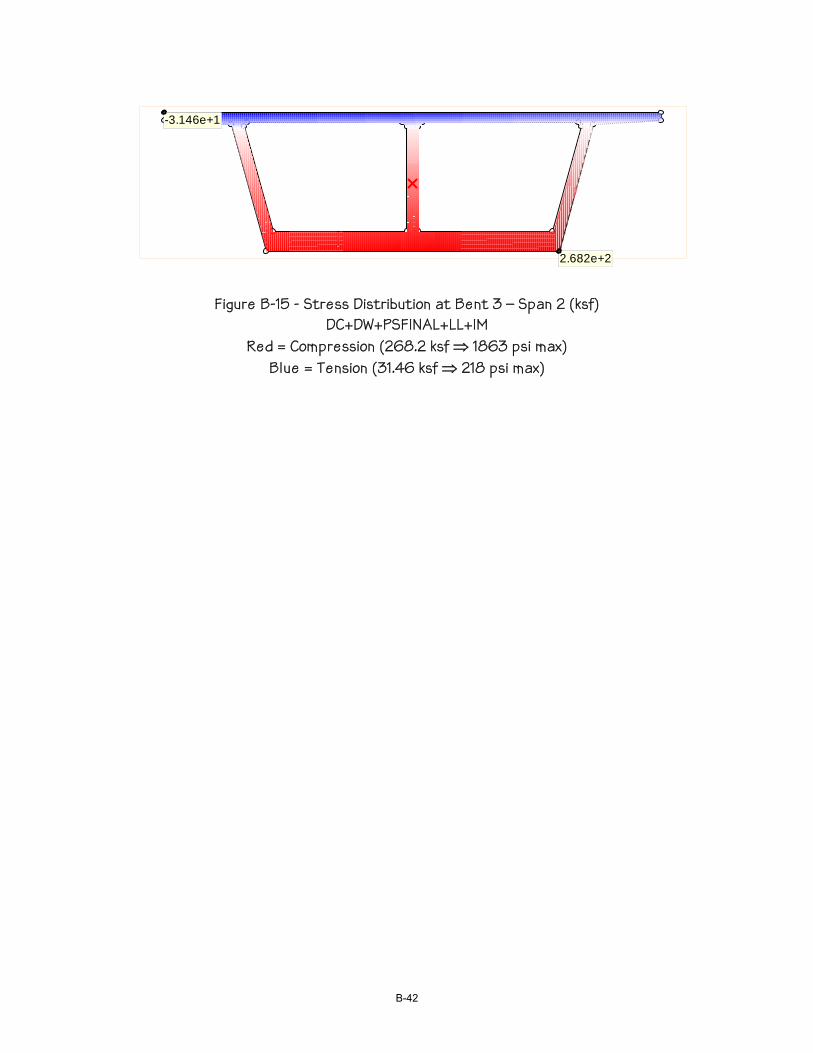
Figure B-15 - Stress Distribution at Bent 3 – Span 2 (ksf)
DC+DW+PSFINAL+LL+IM Red = Compression (268.2 ksf ⇒ 1863 psi max)
Blue = Tension (31.46 ksf ⇒ 218 psi max)
B-42
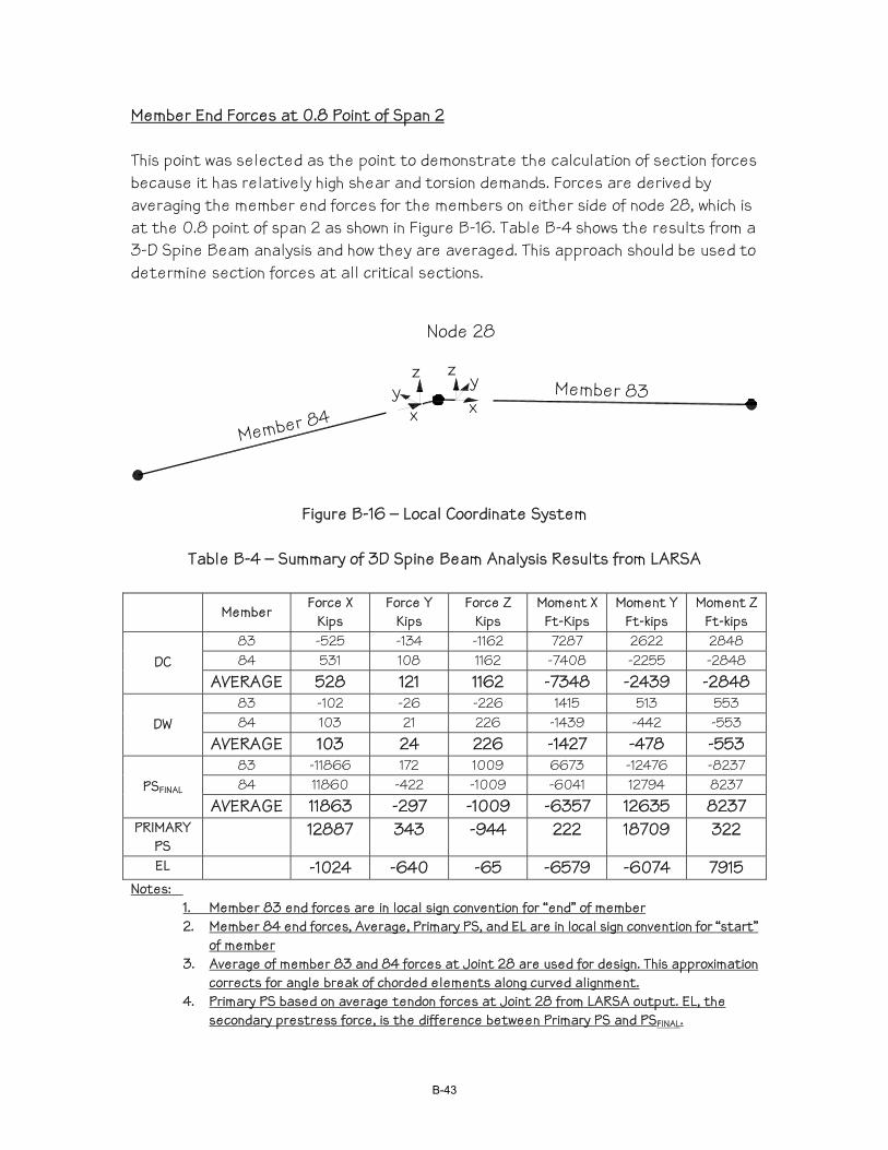
Member End Forces at 0.8 Point of Span 2 This point was selected as the point to demonstrate the calculation of section forces because it has relatively high shear and torsion demands. Forces are derived by averaging the member end forces for the members on either side of node 28, which is at the 0.8 point of span 2 as shown in Figure B-16. Table B-4 shows the results from a 3-D Spine Beam analysis and how they are averaged. This approach should be used to determine section forces at all critical sections.
Member 84Member 83
Node 28
xyzz
yx
Figure B-16 – Local Coordinate System
Table B-4 – Summary of 3D Spine Beam Analysis Results from LARSA
Member
Force X Kips
Force Y Kips
Force Z Kips
Moment X Ft-Kips
Moment Y Ft-kips
Moment Z Ft-kips
83 -525 -134 -1162 7287 2622 2848 84 531 108 1162 -7408 -2255 -2848 DC
AVERAGE 528 121 1162 -7348 -2439 -2848 83 -102 -26 -226 1415 513 553 84 103 21 226 -1439 -442 -553 DW
AVERAGE 103 24 226 -1427 -478 -553 83 -11866 172 1009 6673 -12476 -8237 84 11860 -422 -1009 -6041 12794 8237 PSFINAL
AVERAGE 11863 -297 -1009 -6357 12635 8237 PRIMARY
PS 12887 343 -944 222 18709 322
EL -1024 -640 -65 -6579 -6074 7915 Notes:
1. Member 83 end forces are in local sign convention for “end” of member 2. Member 84 end forces, Average, Primary PS, and EL are in local sign convention for “start”
of member 3. Average of member 83 and 84 forces at Joint 28 are used for design. This approximation
corrects for angle break of chorded elements along curved alignment. 4. Primary PS based on average tendon forces at Joint 28 from LARSA output. EL, the
secondary prestress force, is the difference between Primary PS and PSFINAL.
B-43
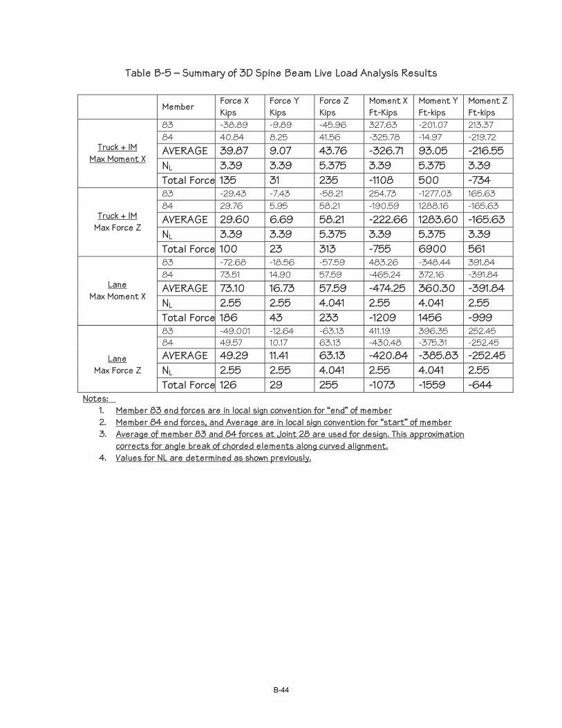
Table B-5 – Summary of 3D Spine Beam Live Load Analysis Results
Member
Force X Kips
Force Y Kips
Force Z Kips
Moment X Ft-Kips
Moment Y Ft-kips
Moment Z Ft-kips
83 -38.89 -9.89 -45.96 327.63 -201.07 213.37 84 40.84 8.25 41.56 -325.78 -14.97 -219.72 AVERAGE 39.87 9.07 43.76 -326.71 93.05 -216.55 NL 3.39 3.39 5.375 3.39 5.375 3.39
Truck + IM Max Moment X
Total Force 135 31 235 -1108 500 -734 83 -29.43 -7.43 -58.21 254.73 -1277.03 165.63 84 29.76 5.95 58.21 -190.59 1288.16 -165.63 AVERAGE 29.60 6.69 58.21 -222.66 1283.60 -165.63 NL 3.39 3.39 5.375 3.39 5.375 3.39
Truck + IM Max Force Z
Total Force 100 23 313 -755 6900 561 83 -72.68 -18.56 -57.59 483.26 -348.44 391.84 84 73.51 14.90 57.59 -465.24 372.16 -391.84 AVERAGE 73.10 16.73 57.59 -474.25 360.30 -391.84 NL 2.55 2.55 4.041 2.55 4.041 2.55
Lane Max Moment X
Total Force 186 43 233 -1209 1456 -999 83 -49.001 -12.64 -63.13 411.19 396.35 252.45 84 49.57 10.17 63.13 -430.48 -375.31 -252.45 AVERAGE 49.29 11.41 63.13 -420.84 -385.83 -252.45 NL 2.55 2.55 4.041 2.55 4.041 2.55
Lane Max Force Z
Total Force 126 29 255 -1073 -1559 -644 Notes:
1. Member 83 end forces are in local sign convention for “end” of member 2. Member 84 end forces, and Average are in local sign convention for “start” of member 3. Average of member 83 and 84 forces at Joint 28 are used for design. This approximation
corrects for angle break of chorded elements along curved alignment. 4. Values for NL are determined as shown previously.
B-44
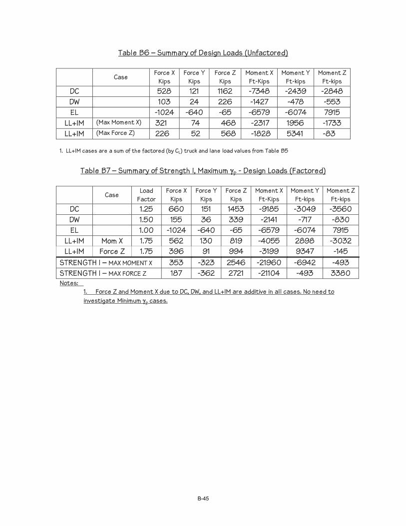
Table B6 – Summary of Design Loads (Unfactored)
Case
Force X Kips
Force Y Kips
Force Z Kips
Moment X Ft-Kips
Moment Y Ft-kips
Moment Z Ft-kips
DC 528 121 1162 -7348 -2439 -2848 DW 103 24 226 -1427 -478 -553 EL -1024 -640 -65 -6579 -6074 7915
LL+IM (Max Moment X) 321 74 468 -2317 1956 -1733 LL+IM (Max Force Z) 226 52 568 -1828 5341 -83
1. LL+IM cases are a sum of the factored (by CL) truck and lane load values from Table B5
Table B7 – Summary of Strength I, Maximum γp - Design Loads (Factored)
Case Load Factor
Force X Kips
Force Y Kips
Force Z Kips
Moment X Ft-Kips
Moment Y Ft-kips
Moment Z Ft-kips
DC 1.25 660 151 1453 -9185 -3049 -3560 DW 1.50 155 36 339 -2141 -717 -830 EL 1.00 -1024 -640 -65 -6579 -6074 7915
LL+IM Mom X 1.75 562 130 819 -4055 2898 -3032 LL+IM Force Z 1.75 396 91 994 -3199 9347 -145
STRENGTH I – MAX MOMENT X 353 -323 2546 -21960 -6942 -493 STRENGTH I – MAX FORCE Z 187 -362 2721 -21104 -493 3380 Notes:
1. Force Z and Moment X due to DC, DW, and LL+IM are additive in all cases. No need to investigate Minimum γp cases.
B-45
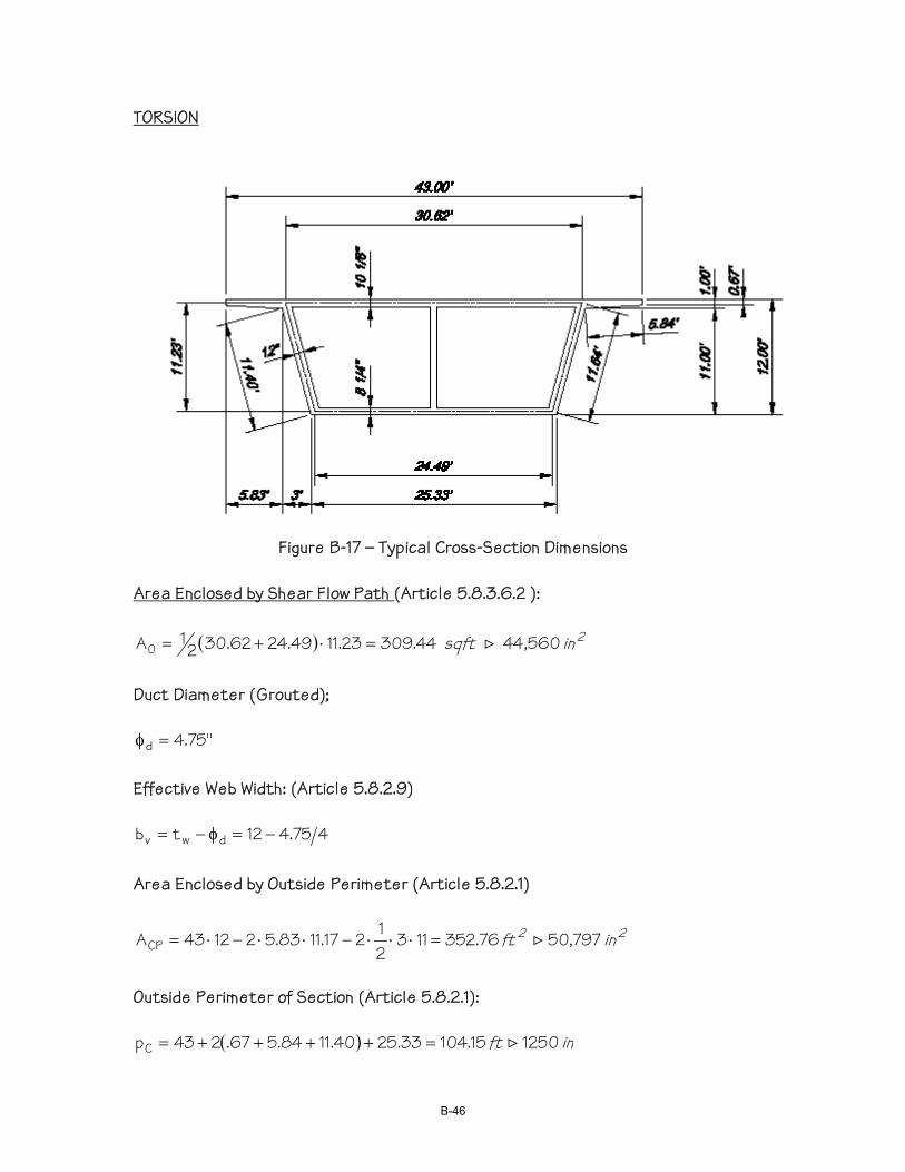
TORSION
Figure B-17 – Typical Cross-Section Dimensions Area Enclosed by Shear Flow Path (Article 5.8.3.6.2 ):
( ) 2in sqft 560,4444.30923.1149.2462.3021A0 >=⋅+=
Duct Diameter (Grouted);
"75.4d =φ Effective Web Width: (Article 5.8.2.9)
475.412tb dwv −=φ−= Area Enclosed by Outside Perimeter (Article 5.8.2.1)
22 in ft 797,5076.35211321217.1183.521243ACP >=⋅⋅⋅−⋅⋅−⋅=
Outside Perimeter of Section (Article 5.8.2.1):
( ) in ft 125015.10433.2540.1184.567.243pC >=++++=
B-46

'c
pc
c
2CP'
ccrf125.0
f1
pA
f125.0T += (Eqn. 5.8.2.1-4)
where:
ksi 040.1144059.86
887,12AP
fx
fpc =
⋅==
Equation 5.8.2.1-5:
23 in in 240,73525.8560.442bA2268,064,21250
797,50p
Av0
2
c
2CP =⋅⋅=≤==
Note: Since bottom slab thickness (8.25)<bv (10.81) use 8.25” for bv in Eqn. 5.8.2.1-5.
kipsft kipsin −−=+⋅=∴ 209,37512,4465125.0
040.117352405125.0Tcr >
Torsional Effects shall be investigated where:
kipsft −=⋅⋅=φ> 372,8209,3790.025.0T25.0T cru < 21,104 ft – kips Therefore, torsion must be investigated. Note that torsion must be investigated in both Case 1 and Case 2. Therefore, the equivalent factored shear force shall be taken as:
0
suu A2
dTV
⋅+ (Eqn. 5.8.2.1-7)
B-47
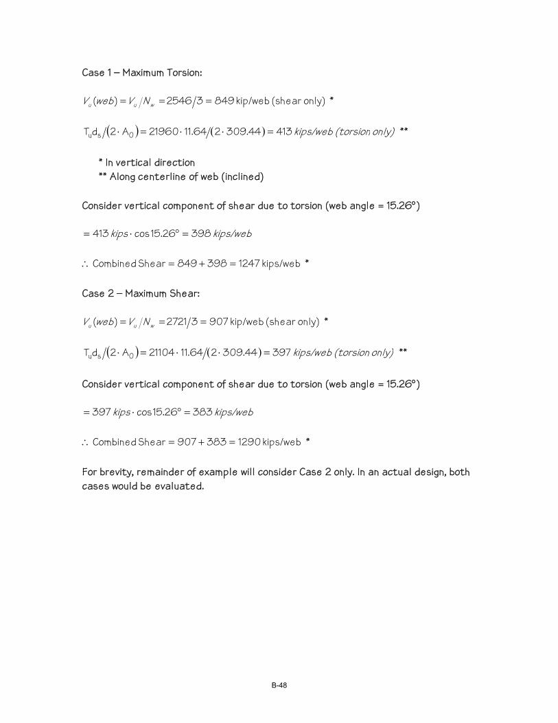
Case 1 – Maximum Torsion:
only) (shear kip/web 84932546)( === wuu NVwebV *
( ) ( ) only) (torsion kips/web 41344.309264.1121960A2dT 0su =⋅⋅=⋅ **
* In vertical direction ** Along centerline of web (inclined)
Consider vertical component of shear due to torsion (web angle = 15.26°)
kips/web kips 39826.15cos413 =°⋅=
kips/web 1247398849Shear Combined =+=∴ * Case 2 – Maximum Shear:
only) (shear kip/web 90732721)( === wuu NVwebV *
( ) ( ) only) (torsion kips/web 39744.309264.1121104A2dT 0su =⋅⋅=⋅ ** Consider vertical component of shear due to torsion (web angle = 15.26°)
kips/web kips 38326.15cos397 =°⋅=
kips/web 1290383907Shear Combined =+=∴ * For brevity, remainder of example will consider Case 2 only. In an actual design, both cases would be evaluated.
B-48
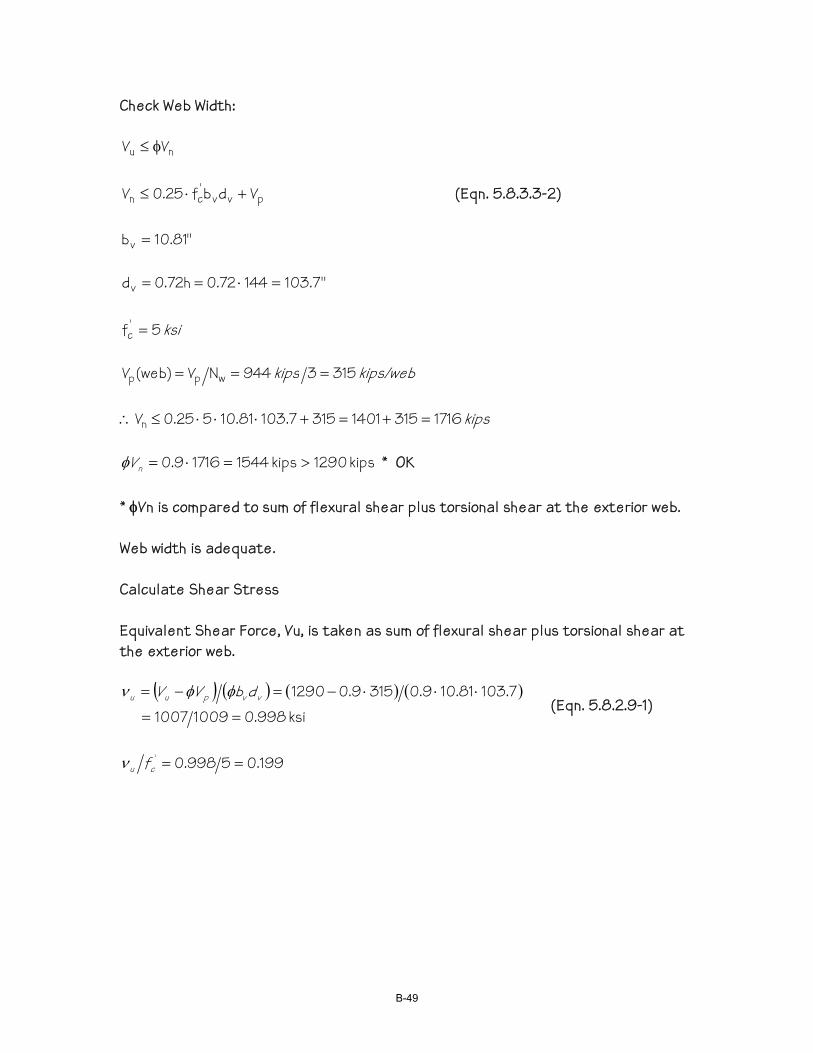
Check Web Width:
nu VV φ≤
pvv'cn Vdbf25.0V +⋅≤ (Eqn. 5.8.3.3-2)
"81.10bv =
"7.10314472.0h72.0dv =⋅==
ksi 5f '
c =
kips/web kips 3153944NV)web(V wpp ===
kips 171631514013157.10381.10525.0Vn =+=+⋅⋅⋅≤∴
kips 1290kips 154417169.0 >=⋅=nVφ * OK * φVn is compared to sum of flexural shear plus torsional shear at the exterior web. Web width is adequate. Calculate Shear Stress Equivalent Shear Force, Vu, is taken as sum of flexural shear plus torsional shear at the exterior web.
( ) ( ) ( ) ( )ksi 998.010091007
7.10381.109.03159.01290
==
⋅⋅⋅−=−= vvpuu dbVV φφν (Eqn. 5.8.2.9-1)
199.05998.0' ==cu fν
B-49
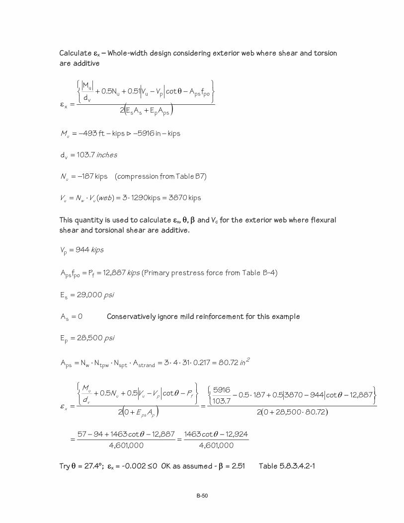
Calculate εx – Whole-width design considering exterior web where shear and torsion are additive
( )pspss
popspuuv
u
x AEAE2
fAcotVV51.0N5.0dM
+⎭⎬⎫
⎩⎨⎧
−θ−++
=ε
kipsin 5916kips ft493 −−−−= >uM
inches 7.103dv =
B7) Table fromon(compressi kips 187−=uN
kips 3870kips12903)( =⋅=⋅= webVNV uwu
This quantity is used to calculate εx, θ, β and Vc for the exterior web where flexural shear and torsional shear are additive.
kips 944Vp =
kips 887,12PfA fpops == (Primary prestress force from Table B-4)
psi 000,29Es =
0As = Conservatively ignore mild reinforcement for this example
psi 500,28Ep =
2in 72.80217.03143ANNNA strandspttpwwps =⋅⋅⋅=⋅⋅⋅=
( ) ( )72.80500,2802
887,12cot94438705.01875.07.103
5916
02
cot5.05.0
⋅+⎩⎨⎧
⎭⎬⎫−−+⋅−
=+
⎩⎨⎧
⎭⎬⎫
−−++
=θθ
εpps
fpuuv
u
x AE
PVVNdM
000,601,4
924,12cot1463000,601,4
887,12cot14639457 −=
−+−=
θθ
Try θ = 27.4°; εx = -0.002 ≤0 OK as assumed - β = 2.51 Table 5.8.3.4.2-1
B-50
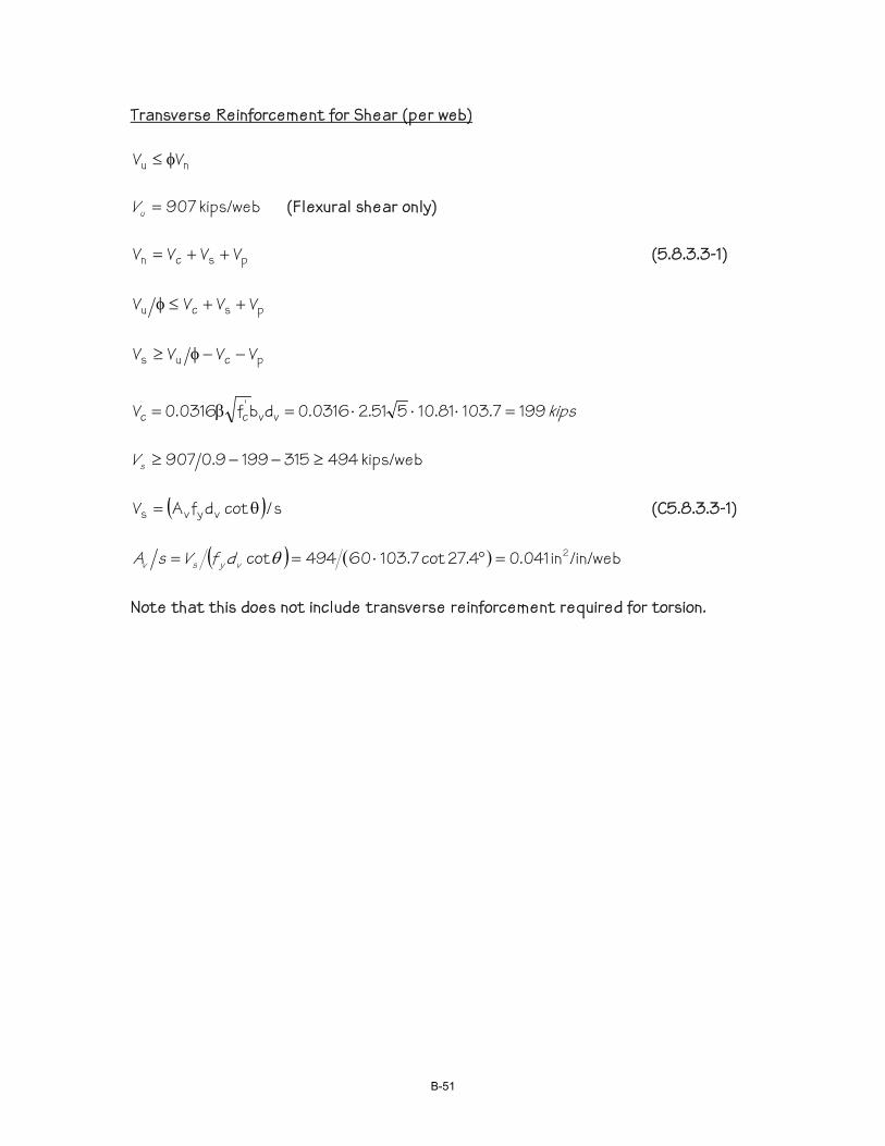
Transverse Reinforcement for Shear (per web)
nu VV φ≤
kips/web 907=uV (Flexural shear only)
pscn VVVV ++= (5.8.3.3-1)
pscu VVVV ++≤φ
pcus VVVV −−φ≥
kips 1997.10381.10551.20316.0dbf0316.0V vv'cc =⋅⋅⋅=β=
kips/web 4943151999.0907 ≥−−≥sV
( ) s/cotdfAV vyvs θ= (C5.8.3.3-1)
( ) ( ) /in/webin 041.04.27cot7.10360494cot 2=°⋅== θvysv dfVsA
Note that this does not include transverse reinforcement required for torsion.
B-51

Transverse Reinforcement for Torsion:
nu TT φ≤
kipsft −= 104,21Tu
( ) scotfAA2T yt0n θ= (5.8.3.6.2-1)
( ) ( ) ( )°⋅⋅⋅÷⋅=θ= 4.27cot60560,4429.012104,21cotfA2TsA y0nt
slabsbottom or top or web exterior per /inchin 2027.0= Combined Transverse Reinforcement: The combined area of both stirrup legs in the web, Astirrups, contribute to Av and At. The maximum spacing of the stirrups, smax, is given by:
⎟⎠⎞
⎜⎝⎛ +=
sA
sA
/As tvstirrupsmax
For #6 stirrups:
( ) ( ) in 94.12027.0041.044.02max =+⋅=s Av = 0.82 in2/ft for both legs Note that this does not account for regional bending of the web or tendon confinement.
B-52
Longitudinal Reinforcement: Whole Width Design For Flexural Shear: (5.8.3.5-1)
⎪⎩
⎪⎨⎧
θ⎪⎭
⎪⎬⎫
−−φ
+φ
+φ
≥+ cotV5.0VVN
5.0dM
fAfA spv
u
c
u
fv
uyspsps
( ) ( )⎩⎨⎧
°⎭⎬⎫⋅−−+
−+
⋅= 4.27cot49435.0944
9.02721
0.111665.0
0.17.1035916
}{ °−+−= 4.27cot741207958357 kips 2055= For Torsion:
y0
hnl fA2
pTA = (5.8.3.6.3-2)
( )0hnyl A2pTfA =
in ft 94039.7849.2464.11262.30ph ==+⋅+=
( ) ( ) kips 2968560,44294090.012104,21fA yl =⋅⋅⋅=
Combined Tension Force:
kips 502329682055 =+=T Note that the final prestress force acting on the section is 12,887 kips and therefore sufficient to satisfy the combined tension force requirement.
B-53
Regional Web Bending: Determine flexural reinforcement required for regional bending of web independent of other load effects. Notice that Fu-in is based on the final prestress force because it will be combined with a live load case and is in the exterior girder, which has the highest combined torsion and flexural shear. From proposed equation 5.10.4.3.1-7 of the proposed specification:
kips/ftft −=⋅⋅
⋅=ψ= − 83.22447.10
78.41342962.17.04/hFM cinuu
Assume 2” cover to #6 stirrups
in 62.9275.0212d =−−= Design charts frequently express Mu as:
2nu bdkM =
This yields a value of kn and the corresponding reinforcing ratio from charts:
( ) ( ) 24762.91212830,22bdMk 22un =⋅⋅==
0055.0=ρ From design charts
/ftin263.062.9120055.0bdAs =⋅⋅=ρ= One leg
Check ultimate moment capacity of this reinforcement
kips 8.376063.0fA ys =⋅=
( ) ( ) in 74.012585.0/6063.0bf85.0/fAa 'cys =⋅⋅⋅==
( ) ( ) 83.222.26121
274.062.98.3790.02
adfAM ysn 2kips/ftft >−=−⋅=−φ=φ OK
Check minimum reinforcement per LRFD 5.7.3.3.2
/ftin 32886/12126/btS 22c =⋅==
B-54
ksi 827.0537.0f37.0f 'cr === (LRFD 5.4.2.6)
kipsft kips/ftin −−=⋅== 85.19238827.0288fSM rccr >
ncr M8.2385.192.1M2.1 φ<−=⋅= kipsft
Required As = 0.63 in2/ft for one leg for regional bending only (#6 @ 8-1/4”) Transverse Web Reinforcement for Combined Actions: Consider Article 5.8.1.5 for combining transverse reinforcement for combined actions of shear, torsion, and regional bending. Tendon confinement is covered in other examples and not repeated here. Sum of reinforcement required for shear, torsion, and regional bending Shear and torsion = 0.82 in2/ft for 2 legs = 0.41 in2/ft for one leg Regional bending = 0.63 in2/ft “ “ ∑ = 1.04 in2/ft “ “ ∴Use #6 @ 5” Note: The effect of dead load of the top slab on transverse web moment is not included in the above calculation because nearly balanced moments are produced over the top of the exterior web. The same is true of a truck live load, because the wheel lines straddle the exterior web and produce very little net transverse moment in the web. However, in a condition where this is not true, these loads should be considered.
B-55
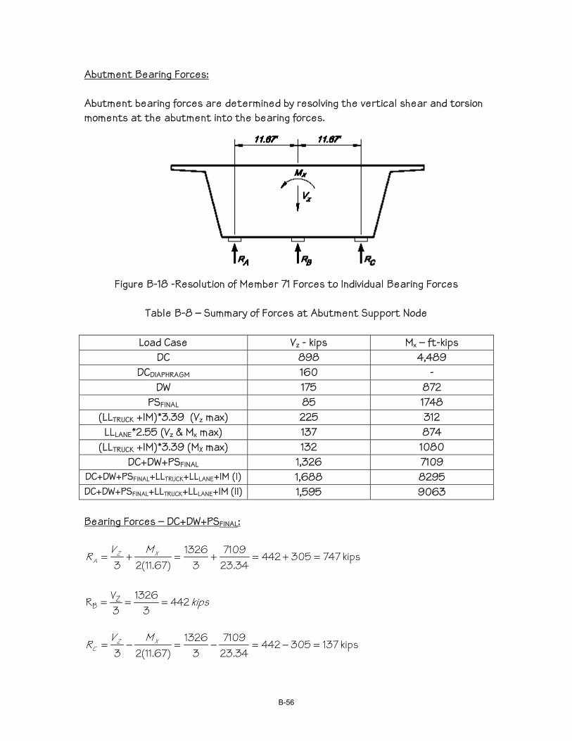
Abutment Bearing Forces: Abutment bearing forces are determined by resolving the vertical shear and torsion moments at the abutment into the bearing forces.
Figure B-18 -Resolution of Member 71 Forces to Individual Bearing Forces
Table B-8 – Summary of Forces at Abutment Support Node
Load Case Vz - kips Mx – ft-kips DC 898 4,489
DCDIAPHRAGM 160 - DW 175 872
PSFINAL 85 1748 (LLTRUCK +IM)*3.39 (Vz max) 225 312
LLLANE*2.55 (Vz & Mx max) 137 874 (LLTRUCK +IM)*3.39 (MX max) 132 1080
DC+DW+PSFINAL 1,326 7109 DC+DW+PSFINAL+LLTRUCK+LLLANE+IM (I) 1,688 8295 DC+DW+PSFINAL+LLTRUCK+LLLANE+IM (II) 1,595 9063
Bearing Forces – DC+DW+PSFINAL:
kips 74730544234.23
71093
1326)67.11(23
=+=+=+= XZA
MVR
kips 4423
13263VR Z
B ===
kips 13730544234.23
71093
1326)67.11(23
=−=−=−= XZC
MVR
B-56
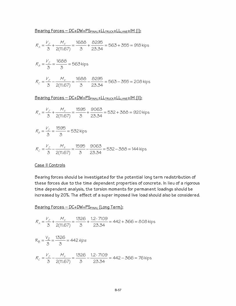
Bearing Forces – DC+DW+PSFINAL+LLTRUCK+LLLANE+IM (I):
kips 91835556334.23
82953
1688)67.11(23
=+=+=+= XZA
MVR
kips 5633
16883
=== ZB
VR
kips 20835556334.23
82953
1688)67.11(23
=−=−=−= XZC
MVR
Bearing Forces – DC+DW+PSFINAL+LLTRUCK+LLLANE+IM (II):
kips 92038853234.23
90633
1595)67.11(23
=+=+=+= XZA
MVR
kips 5323
15953
=== ZB
VR
kips 14438853234.23
90633
1595)67.11(23
=−=−=−= XZC
MVR
Case II Controls Bearing forces should be investigated for the potential long term redistribution of these forces due to the time dependent properties of concrete. In lieu of a rigorous time dependent analysis, the torsion moments for permanent loadings should be increased by 20%. The effect of a super imposed live load should also be considered. Bearing Forces – DC+DW+PSFINAL (Long Term):
kips 80836644234.23
71092.13
1326)67.11(23
=+=⋅
+=+= XZA
MVR
kips 4423
13263VR Z
B ===
kips 7636644234.23
71092.13
1326)67.11(23
=−=⋅
−=−= XZC
MVR
B-57
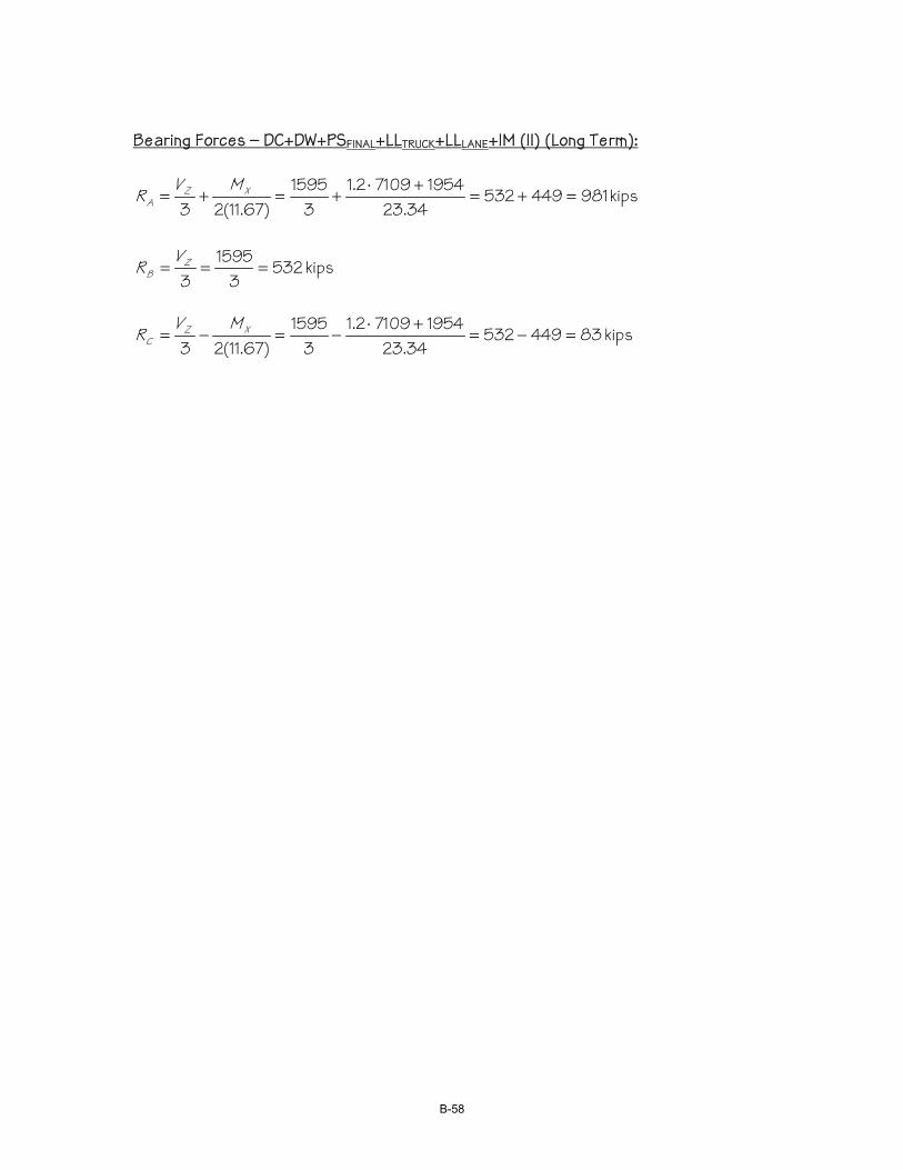
Bearing Forces – DC+DW+PSFINAL+LLTRUCK+LLLANE+IM (II) (Long Term):
kips 98144953234.23
195471092.13
1595)67.11(23
=+=+⋅
+=+= XZA
MVR
kips 5323
15953
=== ZB
VR
kips 8344953234.23
195471092.13
1595)67.11(23
=−=+⋅
−=−= XZC
MVR
B-58
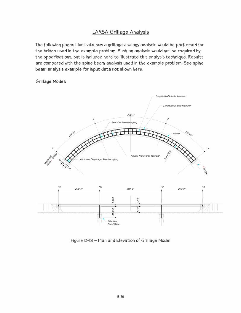
LARSA Grillage Analysis
The following pages illustrate how a grillage analogy analysis would be performed for the bridge used in the example problem. Such an analysis would not be required by the specifications, but is included here to illustrate this analysis technique. Results are compared with the spine beam analysis used in the example problem. See spine beam analysis example for input data not shown here. Grillage Model:
Figure B-19 – Plan and Elevation of Grillage Model
B-59
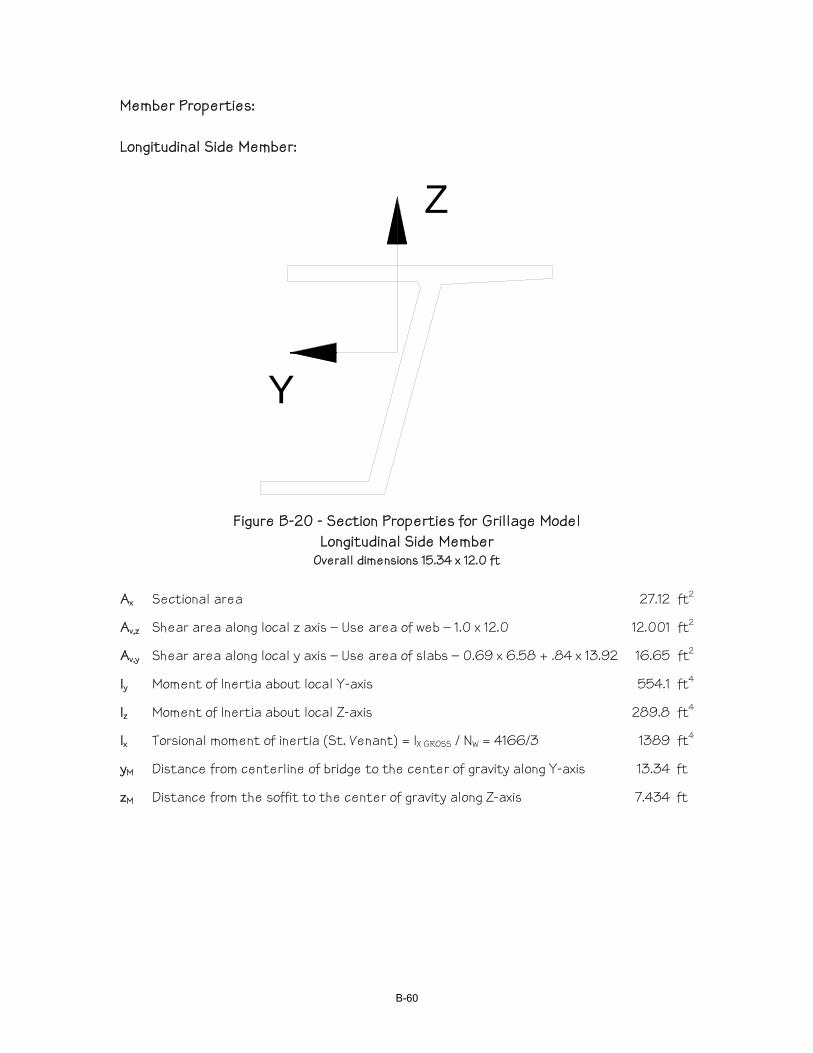
Member Properties: Longitudinal Side Member:
Z
Y
Figure B-20 - Section Properties for Grillage Model Longitudinal Side Member
Overall dimensions 15.34 x 12.0 ft Ax Sectional area 27.12 ft2
Av,z Shear area along local z axis – Use area of web – 1.0 x 12.0 12.001 ft2
Av,y Shear area along local y axis – Use area of slabs – 0.69 x 6.58 + .84 x 13.92 16.65 ft2
Iy Moment of Inertia about local Y-axis 554.1 ft4
Iz Moment of Inertia about local Z-axis 289.8 ft4
Ix Torsional moment of inertia (St. Venant) = IX GROSS / NW = 4166/3 1389 ft4
yM Distance from centerline of bridge to the center of gravity along Y-axis 13.34 ft
zM Distance from the soffit to the center of gravity along Z-axis 7.434 ft
B-60
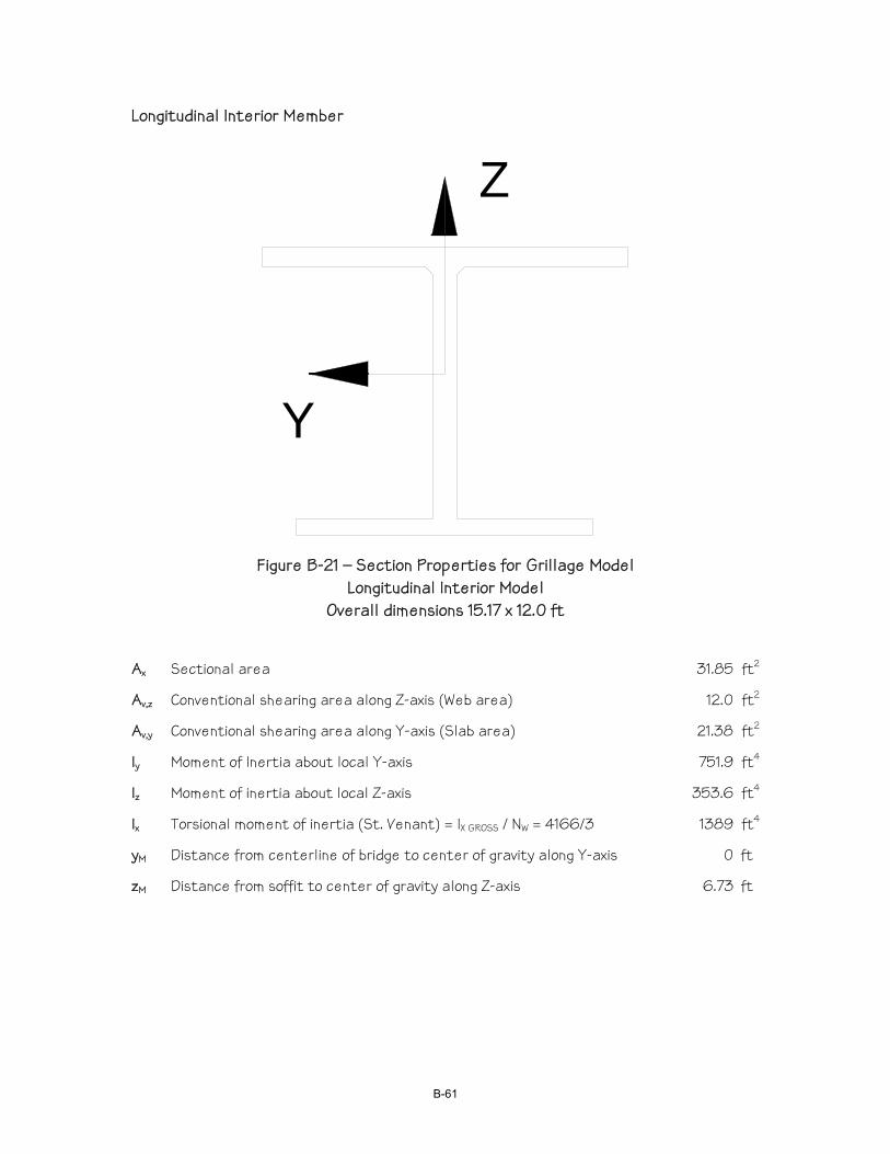
Longitudinal Interior Member
Y
Z
Figure B-21 – Section Properties for Grillage Model Longitudinal Interior Model
Overall dimensions 15.17 x 12.0 ft
Ax Sectional area 31.85 ft2
Av,z Conventional shearing area along Z-axis (Web area) 12.0 ft2
Av,y Conventional shearing area along Y-axis (Slab area) 21.38 ft2
Iy Moment of Inertia about local Y-axis 751.9 ft4
Iz Moment of inertia about local Z-axis 353.6 ft4
Ix Torsional moment of inertia (St. Venant) = IX GROSS / NW = 4166/3 1389 ft4
yM Distance from centerline of bridge to center of gravity along Y-axis 0 ft
zM Distance from soffit to center of gravity along Z-axis 6.73 ft
B-61
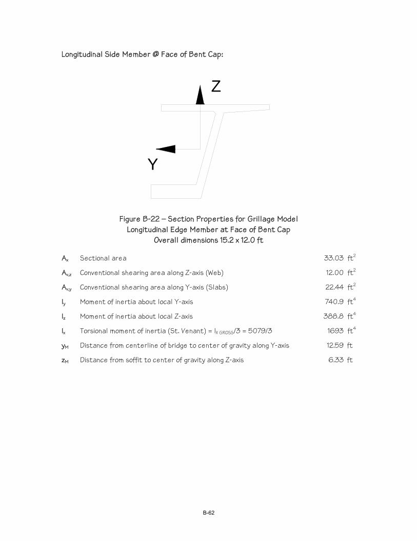
Longitudinal Side Member @ Face of Bent Cap:
Z
Y
Figure B-22 – Section Properties for Grillage Model Longitudinal Edge Member at Face of Bent Cap
Overall dimensions 15.2 x 12.0 ft Ax Sectional area 33.03 ft2
Av,z Conventional shearing area along Z-axis (Web) 12.00 ft2
Av,y Conventional shearing area along Y-axis (Slabs) 22.44 ft2
Iy Moment of inertia about local Y-axis 740.9 ft4
Iz Moment of inertia about local Z-axis 388.8 ft4
Ix Torsional moment of inertia (St. Venant) = IX GROSS/3 = 5079/3 1693 ft4
yM Distance from centerline of bridge to center of gravity along Y-axis 12.59 ft
zM Distance from soffit to center of gravity along Z-axis 6.33 ft
B-62

Longitudinal Interior Member at Face of Bent Cap:
Y
Z
Figure B-23 – Section Properties for Grillage Model Longitudinal Interior Member at Face of Bent Cap
Overall dimensions 15.17 x 12.0 ft Ax Sectional area 44.38 ft2
Av,z Conventional shearing area along Z-axis 12.00 ft2
Av,y Conventional shearing area along Y-axis 34.97 ft2
Iy Moment of inertia about local Y-axis 1028 ft4
Iz Moment of inertia about local Z-axis 538.7 ft4
Ix Torsional moment of inertia (St. Venant) = IX GROSS/3 = 5079/3 1693 ft4
yM Distance from centerline of bridge to center of gravity along Y-axis 0 ft
zM Distance from soffit to center of gravity along Z-axis 5.17 ft
B-63
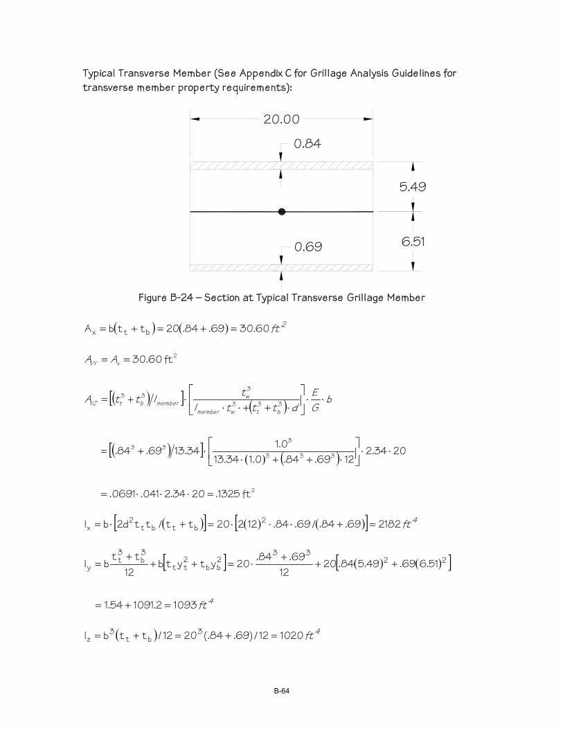
Typical Transverse Member (See Appendix C for Grillage Analysis Guidelines for transverse member property requirements):
20.00
0.84
0.69 6.51
5.49
Figure B-24 – Section at Typical Transverse Grillage Member
( ) ( ) 2ft 60.3069.84.20ttbA btx =+=+=
2 ft60.30== xVY AA
( )[ ] ( )
( )[ ]( ) ( )
2
333
333
333
333
ft1325.2034.2041.0691.
2034.21269.84.0.134.13
0.134.1369.84.
=⋅⋅⋅=
⋅⋅⎥⎦
⎤⎢⎣
⎡⋅++⋅
⋅+=
⋅⋅⎥⎦
⎤⎢⎣
⎡⋅++⋅⋅
⋅+= bGE
dtttltlttA
btwmember
wmemberbtVZ
( )[ ] ( ) ( )[ ] 4ft 218269.84./69.84.12220tt/ttd2bI 2
btbt2
x =+⋅⋅⋅=+⋅=
[ ] ( ) ( )[ ]
4ft 10932.109154.1
51.669.49.584.2012
69.84.20ytytb12
ttbI 22
332bb
2tt
3b
3t
y
=+=
+++
⋅=+++
=
( ) 4ft 102012/)69.84(.2012/ttbI 3
bt3
z =+=+=
B-64

Transverse Member Adjacent to Bent Cap (See Appendix C):
20.00
0.823 (AVG)
0.84
6.05
5.95
Figure B-25 – Transverse Member Adjacent to Bent Cap
( ) ( ) 2ft 26.33823.84.20ttbA btx =+=+=
2 ft26.33== xVY AA
( )[ ] ( )
( )[ ]( ) ( )
2
333
333
333
333
ft149.2034.203684.08622.
2034.212823.84.0.134.13
0.134.13823.84.
=⋅⋅⋅=
⋅⋅⎥⎦
⎤⎢⎣
⎡⋅++⋅
⋅+=
⋅⋅⎥⎦
⎤⎢⎣
⎡⋅++⋅⋅
⋅+= bGE
dtttltlttA
btwmember
wmemberbtVZ
( )[ ] ( ) ( )[ ] 4ft 2394823.84./823.84.12220tt/ttd2bI 2
btbt2
x =+⋅⋅⋅=+⋅=
[ ] ( ) ( )[ ]
4ft 11992.111979.1
05.6823.95.584.2012
823.84.20ytytb12
ttbI 22
332bb
2tt
3b
3t
y
=+=
+++
⋅=+++
=
( ) 4ft 119912/)823.84(.2012/ttbI 3
bt3
z =+=+=
B-65
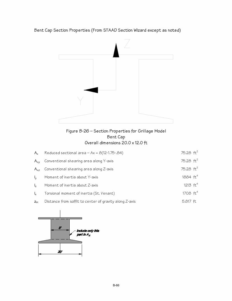
Bent Cap Section Properties (From STAAD Section Wizard except as noted)
Figure B-26 – Section Properties for Grillage Model Bent Cap
Overall dimensions 20.0 x 12.0 ft Ax Reduced sectional area – Ax = 8(12-1.75-.84) 75.28 ft2
Av,y Conventional shearing area along Y-axis 75.28 ft2
Av,z Conventional shearing area along Z-axis 75.28 ft2
Iy Moment of inertia about Y-axis 1884 ft4
Iz Moment of inertia about Z-axis 1213 ft4
Ix Torsional moment of inertia (St. Venant) 1708 ft4
zM Distance from soffit to center of gravity along Z-axis 5.817 ft
B-66
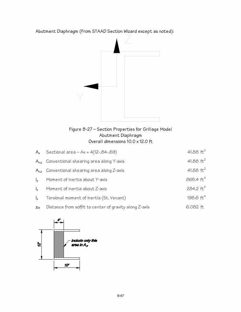
Abutment Diaphragm (From STAAD Section Wizard except as noted):
Figure B-27 – Section Properties for Grillage Model Abutment Diaphragm
Overall dimensions 10.0 x 12.0 ft Ax Sectional area – Ax = 4(12-.84-.69) 41.88 ft2
Av,y Conventional shearing area along Y-axis 41.88 ft2
Av,z Conventional shearing area along Z-axis 41.88 ft2
Iy Moment of Inertia about Y-axis 865.4 ft4
Iz Moment of inertia about Z-axis 284.2 ft4
Ix Torsional moment of inertia (St. Venant) 198.6 ft4
zM Distance from soffit to center of gravity along Z-axis 6.082 ft
B-67
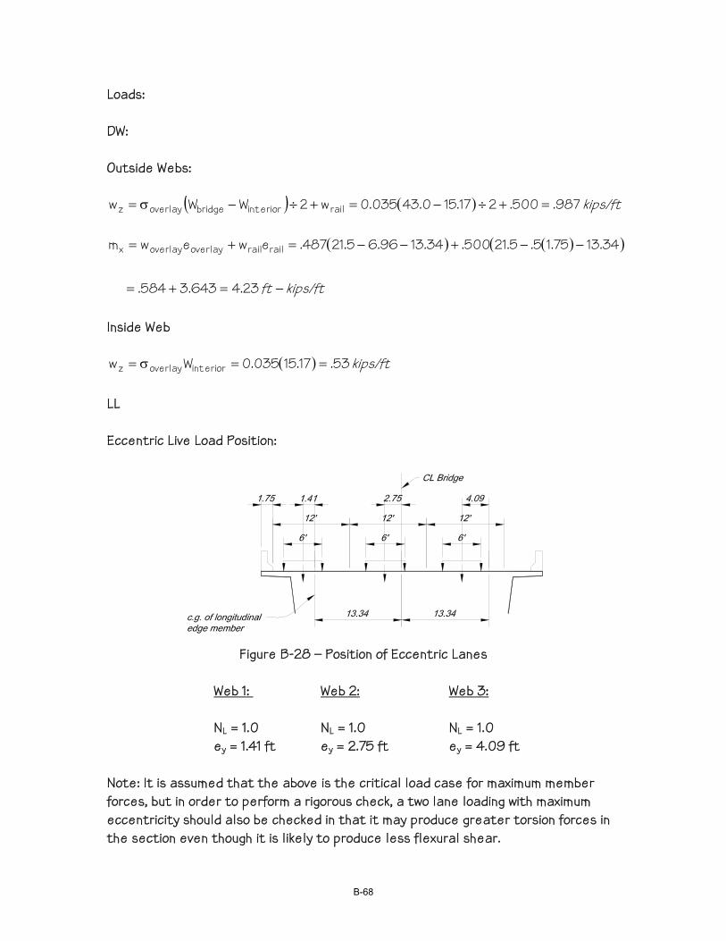
Loads: DW: Outside Webs:
( ) ( ) kips/ft 987.500.217.150.43035.0w2WWw raileriorintbridgeoverlayz =+÷−=+÷−σ=
( ) ( )( )
kips/ftft −=+=
−−+−−=+=
23.4643.3584.
34.1375.15.5.21500.34.1396.65.21487.ewewm railrailoverlayoverlayx
Inside Web
( ) kips/ft 53.17.15035.0Ww eriorintoverlayz ==σ= LL Eccentric Live Load Position:
Figure B-28 – Position of Eccentric Lanes
Web 1: Web 2: Web 3:
NL = 1.0 NL = 1.0 NL = 1.0 ey = 1.41 ft ey = 2.75 ft ey = 4.09 ft
Note: It is assumed that the above is the critical load case for maximum member forces, but in order to perform a rigorous check, a two lane loading with maximum eccentricity should also be checked in that it may produce greater torsion forces in the section even though it is likely to produce less flexural shear.
B-68
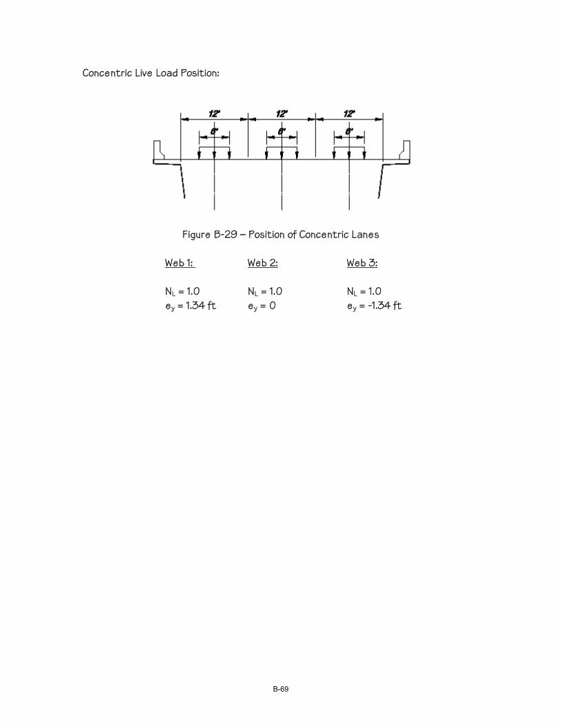
Concentric Live Load Position:
Figure B-29 – Position of Concentric Lanes
Web 1: Web 2: Web 3:
NL = 1.0 NL = 1.0 NL = 1.0 ey = 1.34 ft ey = 0 ey = -1.34 ft
B-69

B-70

Grillage Analysis Input and Results Selected LARSA Output
B-71
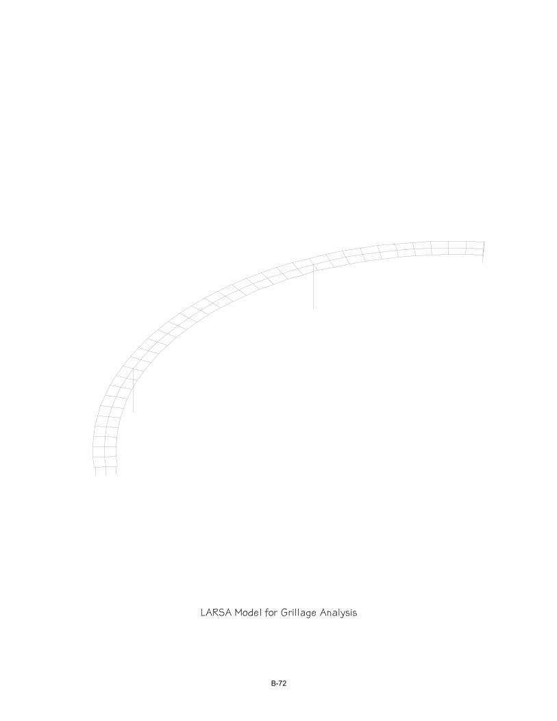
LARSA Model for Grillage Analysis
B-72
187
186
185
184
183
182
181
180
179
178
177
1
76
175
1
74
173
1
72
171
1
70
169
1
68
167
1
66
165
164
163
162
161
160
159
158
157
156
155
154
153
152
151
150
149
148
147
1
46
145
144
143
139
1
38
137
1
36
135
1
34
133
1
32
128
127
126
125
124
123
122
121
120
119
118
1
17
116
1
15
114
1
13
112
1
11
110
1
09
108
107
106
105
104
103
102
101
100
99
98
97
96
95
94
93
92
91
90
89
88
87
86
85
84
83
82
81
80
79
78
77
76
75
74
73
72
71
70
69
68
67
66
65
64
63
62
61
60
59
58
57
56
55
54
53
52
51
50
49
48
47
46
45
44 4
3
42 4
1
40 3
9
38 3
7
36 35
34
33
32
31
30
29
28
27
26
25
24
23
22
21
20
19
18
17
16
15
14
13
12
11
10
9
8
7
6
5
4
3
2
1
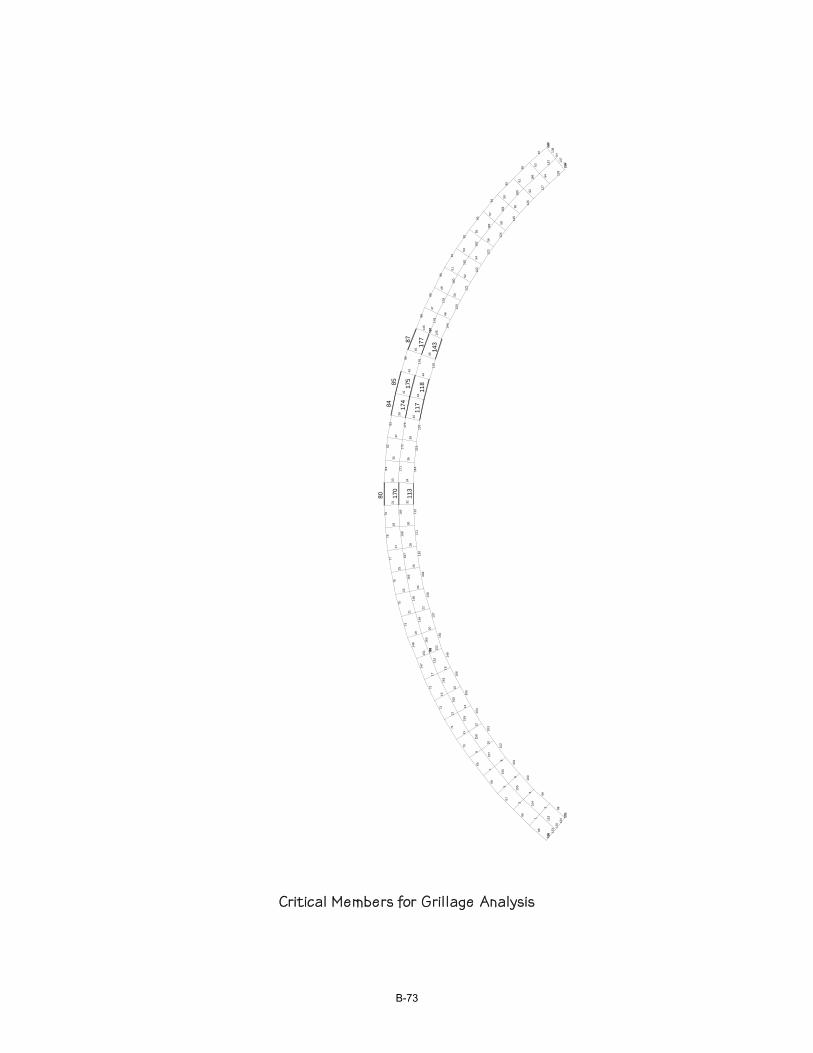
Critical Members for Grillage Analysis
B-73
Name Modulus of Elasticity (lb/in²) Poisson Ratio Shear Modulus
(lb/in²) Unit Weight (lb/in³) Thermal Expansion (1/ °F *10^-6) Assigned
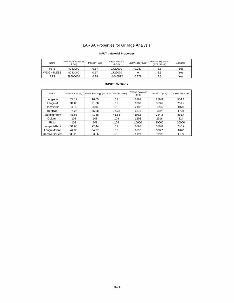
Fc_5 4031000 0.17 1722000 0.087 5.5 YesWEIGHTLESS 4031000 0.17 1722000 0 5.5 Yes
PSS 28500000 0.29 11046512 0.278 5.5 Yes
Name Section Area (ft²) Shear Area in yy (ft²) Shear Area in zz (ft²) Torsion Constant (ft^4) Inertia Izz (ft^4) Inertia Iyy (ft^4)
Longside 27.12 16.65 12 1389 289.8 554.1Longmid 31.85 21.38 12 1389 353.6 751.9
Transverse 30.6 30.6 0.13 2182 1093 1020Bentcap 75.28 75.28 75.28 1213 1884 1708
Abutdiapragm 41.88 41.88 41.88 198.6 284.2 865.4Column 108 108 108 1296 2916 324
Rigid 108 108 108 10000 10000 10000LongsideBent 31.85 22.44 12 1693 388.8 740.9LongmidBent 44.38 34.97 12 1693 538.7 1028
TransverseBent 33.26 33.26 0.15 1197 1199 1109
LARSA Properties for Grillage Analysis
INPUT : Material Properties
INPUT : Sections
B-74

ID X (ft) Y (ft) Z (ft) Translation DOF Rotation DOF Displacement
UCS Assignment
1 636.43 -1478.45 0 all free all free Global Yes2 617.1 -1478.45 0 all free all free Global Yes3 655.74 -1479.42 0 all free all free Global Yes4 597.79 -1479.42 0 all free all free Global Yes5 636.77 -1465.11 0 all free all free Global Yes6 616.77 -1465.11 0 all free all free Global Yes7 656.74 -1466.11 0 all free all free Global Yes8 596.79 -1466.11 0 all free all free Global Yes9 674.97 -1481.35 0 all free all free Global Yes10 578.56 -1481.35 0 all free all free Global Yes11 637.1 -1451.78 0 all free all free Global Yes12 616.43 -1451.78 0 all free all free Global Yes13 676.64 -1468.11 0 all free all free Global Yes14 576.9 -1468.11 0 all free all free Global Yes15 657.74 -1452.81 0 all free all free Global Yes16 595.79 -1452.81 0 all free all free Global Yes17 694.09 -1484.23 0 all free all free Global Yes18 559.45 -1484.23 0 all free all free Global Yes19 678.3 -1454.87 0 all free all free Global Yes20 575.23 -1454.87 0 all free all free Global Yes21 696.41 -1471.1 0 all free all free Global Yes22 557.12 -1471.1 0 all free all free Global Yes23 713.03 -1488.07 0 all free all free Global Yes24 540.5 -1488.07 0 all free all free Global Yes25 698.73 -1457.96 0 all free all free Global Yes26 554.8 -1457.96 0 all free all free Global Yes27 716.01 -1475.07 0 all free all free Global Yes28 537.52 -1475.07 0 all free all free Global Yes29 731.76 -1492.86 0 all free all free Global Yes30 521.77 -1492.86 0 all free all free Global Yes31 718.99 -1462.07 0 all free all free Global Yes32 534.55 -1462.07 0 all free all free Global Yes33 735.39 -1480.02 0 all free all free Global Yes34 518.15 -1480.02 0 all free all free Global Yes35 739.01 -1467.18 0 all free all free Global Yes36 514.53 -1467.18 0 all free all free Global Yes37 750.23 -1498.57 0 all free all free Global Yes38 503.3 -1498.57 0 all free all free Global Yes39 754.49 -1485.93 0 all free all free Global Yes40 499.04 -1485.93 0 all free all free Global Yes41 758.75 -1473.29 0 all free all free Global Yes42 494.78 -1473.29 0 all free all free Global Yes43 484.87 -1504.5 0 all free all free Global Yes44 768.66 -1504.5 0 all free all free Global Yes
LARSA Joint Data
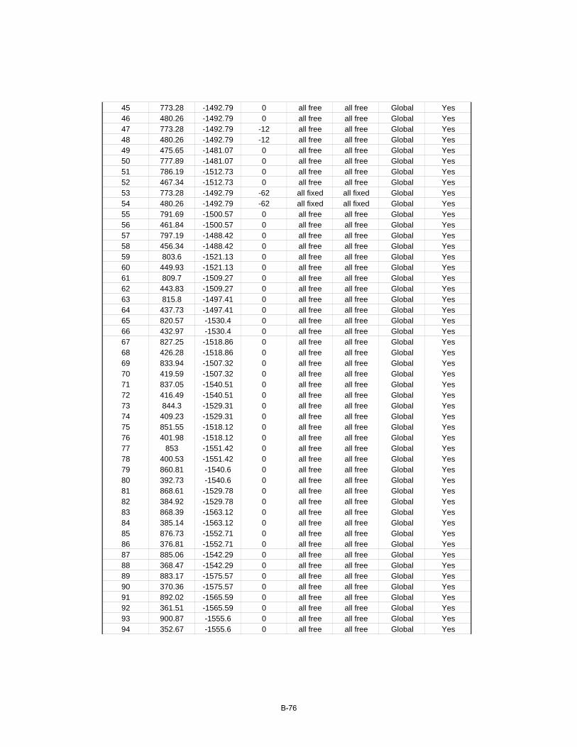
INPUT : Joints
B-75
45 773.28 -1492.79 0 all free all free Global Yes46 480.26 -1492.79 0 all free all free Global Yes47 773.28 -1492.79 -12 all free all free Global Yes48 480.26 -1492.79 -12 all free all free Global Yes49 475.65 -1481.07 0 all free all free Global Yes50 777.89 -1481.07 0 all free all free Global Yes51 786.19 -1512.73 0 all free all free Global Yes52 467.34 -1512.73 0 all free all free Global Yes53 773.28 -1492.79 -62 all fixed all fixed Global Yes54 480.26 -1492.79 -62 all fixed all fixed Global Yes55 791.69 -1500.57 0 all free all free Global Yes56 461.84 -1500.57 0 all free all free Global Yes57 797.19 -1488.42 0 all free all free Global Yes58 456.34 -1488.42 0 all free all free Global Yes59 803.6 -1521.13 0 all free all free Global Yes60 449.93 -1521.13 0 all free all free Global Yes61 809.7 -1509.27 0 all free all free Global Yes62 443.83 -1509.27 0 all free all free Global Yes63 815.8 -1497.41 0 all free all free Global Yes64 437.73 -1497.41 0 all free all free Global Yes65 820.57 -1530.4 0 all free all free Global Yes66 432.97 -1530.4 0 all free all free Global Yes67 827.25 -1518.86 0 all free all free Global Yes68 426.28 -1518.86 0 all free all free Global Yes69 833.94 -1507.32 0 all free all free Global Yes70 419.59 -1507.32 0 all free all free Global Yes71 837.05 -1540.51 0 all free all free Global Yes72 416.49 -1540.51 0 all free all free Global Yes73 844.3 -1529.31 0 all free all free Global Yes74 409.23 -1529.31 0 all free all free Global Yes75 851.55 -1518.12 0 all free all free Global Yes76 401.98 -1518.12 0 all free all free Global Yes77 853 -1551.42 0 all free all free Global Yes78 400.53 -1551.42 0 all free all free Global Yes79 860.81 -1540.6 0 all free all free Global Yes80 392.73 -1540.6 0 all free all free Global Yes81 868.61 -1529.78 0 all free all free Global Yes82 384.92 -1529.78 0 all free all free Global Yes83 868.39 -1563.12 0 all free all free Global Yes84 385.14 -1563.12 0 all free all free Global Yes85 876.73 -1552.71 0 all free all free Global Yes86 376.81 -1552.71 0 all free all free Global Yes87 885.06 -1542.29 0 all free all free Global Yes88 368.47 -1542.29 0 all free all free Global Yes89 883.17 -1575.57 0 all free all free Global Yes90 370.36 -1575.57 0 all free all free Global Yes91 892.02 -1565.59 0 all free all free Global Yes92 361.51 -1565.59 0 all free all free Global Yes93 900.87 -1555.6 0 all free all free Global Yes94 352.67 -1555.6 0 all free all free Global Yes
B-76

95 897.32 -1588.75 0 all free all free Global Yes96 356.21 -1588.75 0 all free all free Global Yes97 906.65 -1579.22 0 all free all free Global Yes98 346.88 -1579.22 0 all free all free Global Yes99 915.99 -1569.69 0 all free all free Global Yes100 337.55 -1569.69 0 all free all free Global Yes101 910.79 -1602.62 0 all free all free Global Yes102 342.75 -1602.62 0 all free all free Global Yes103 920.59 -1593.57 0 all free all free Global Yes104 332.95 -1593.57 0 all free all free Global Yes105 930.38 -1584.51 0 all free all free Global Yes106 323.15 -1584.51 0 all free all free Global Yes107 923.54 -1617.14 0 all free all free Global Yes108 329.99 -1617.14 0 all free all free Global Yes109 924.83 -1616.07 0 all free all free Global Yes110 328.71 -1616.07 0 all free all free Global Yes111 924.83 -1616.07 -12 z fixed all free Global Yes112 328.71 -1616.07 -12 z fixed all free Global Yes113 933.78 -1608.59 0 all free all free Global Yes114 319.75 -1608.59 0 all free all free Global Yes115 933.78 -1608.59 -12 z fixed all free Global Yes116 319.75 -1608.59 -12 z fixed all free Global Yes117 942.74 -1601.11 0 all free all free Global Yes118 310.79 -1601.11 0 all free all free Global Yes119 942.74 -1601.11 -12 z fixed all free Global Yes120 310.79 -1601.11 -12 z fixed all free Global Yes121 944.02 -1600.04 0 all free all free Global Yes122 309.51 -1600.04 0 all free all free Global Yes
B-77
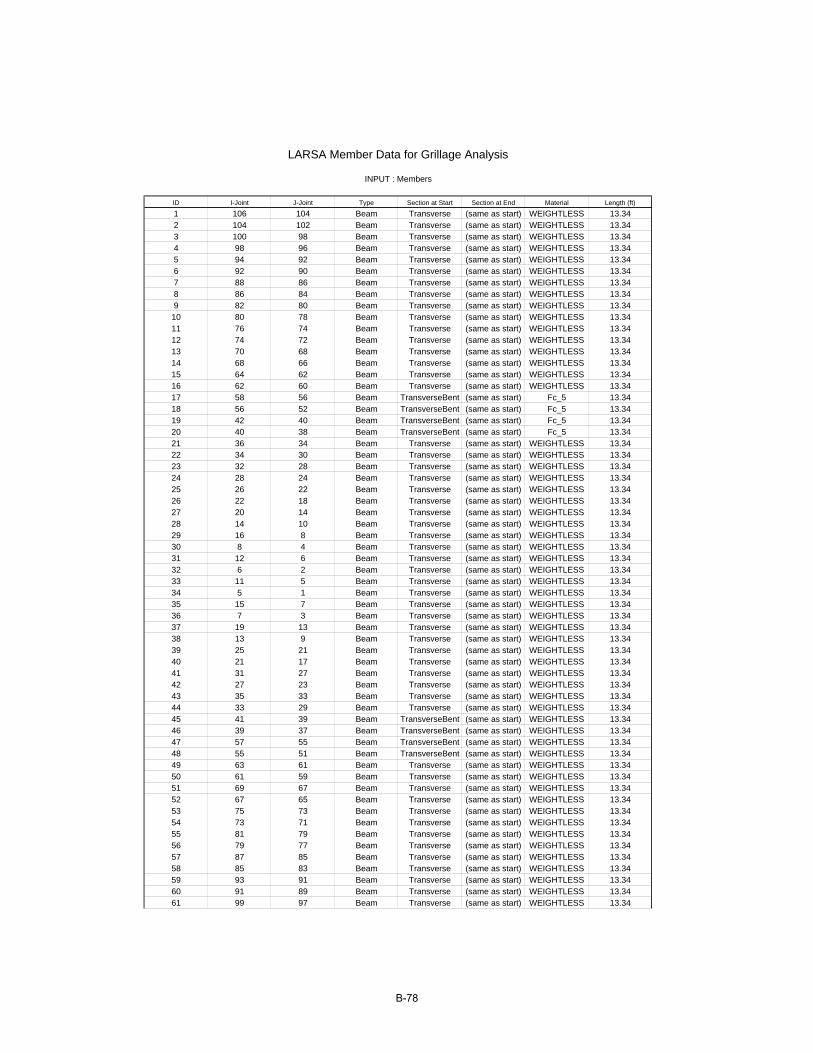
ID I-Joint J-Joint Type Section at Start Section at End Material Length (ft)
1 106 104 Beam Transverse (same as start) WEIGHTLESS 13.342 104 102 Beam Transverse (same as start) WEIGHTLESS 13.343 100 98 Beam Transverse (same as start) WEIGHTLESS 13.344 98 96 Beam Transverse (same as start) WEIGHTLESS 13.345 94 92 Beam Transverse (same as start) WEIGHTLESS 13.346 92 90 Beam Transverse (same as start) WEIGHTLESS 13.347 88 86 Beam Transverse (same as start) WEIGHTLESS 13.348 86 84 Beam Transverse (same as start) WEIGHTLESS 13.349 82 80 Beam Transverse (same as start) WEIGHTLESS 13.3410 80 78 Beam Transverse (same as start) WEIGHTLESS 13.3411 76 74 Beam Transverse (same as start) WEIGHTLESS 13.3412 74 72 Beam Transverse (same as start) WEIGHTLESS 13.3413 70 68 Beam Transverse (same as start) WEIGHTLESS 13.3414 68 66 Beam Transverse (same as start) WEIGHTLESS 13.3415 64 62 Beam Transverse (same as start) WEIGHTLESS 13.3416 62 60 Beam Transverse (same as start) WEIGHTLESS 13.3417 58 56 Beam TransverseBent (same as start) Fc_5 13.3418 56 52 Beam TransverseBent (same as start) Fc_5 13.3419 42 40 Beam TransverseBent (same as start) Fc_5 13.3420 40 38 Beam TransverseBent (same as start) Fc_5 13.3421 36 34 Beam Transverse (same as start) WEIGHTLESS 13.3422 34 30 Beam Transverse (same as start) WEIGHTLESS 13.3423 32 28 Beam Transverse (same as start) WEIGHTLESS 13.3424 28 24 Beam Transverse (same as start) WEIGHTLESS 13.3425 26 22 Beam Transverse (same as start) WEIGHTLESS 13.3426 22 18 Beam Transverse (same as start) WEIGHTLESS 13.3427 20 14 Beam Transverse (same as start) WEIGHTLESS 13.3428 14 10 Beam Transverse (same as start) WEIGHTLESS 13.3429 16 8 Beam Transverse (same as start) WEIGHTLESS 13.3430 8 4 Beam Transverse (same as start) WEIGHTLESS 13.3431 12 6 Beam Transverse (same as start) WEIGHTLESS 13.3432 6 2 Beam Transverse (same as start) WEIGHTLESS 13.3433 11 5 Beam Transverse (same as start) WEIGHTLESS 13.3434 5 1 Beam Transverse (same as start) WEIGHTLESS 13.3435 15 7 Beam Transverse (same as start) WEIGHTLESS 13.3436 7 3 Beam Transverse (same as start) WEIGHTLESS 13.3437 19 13 Beam Transverse (same as start) WEIGHTLESS 13.3438 13 9 Beam Transverse (same as start) WEIGHTLESS 13.3439 25 21 Beam Transverse (same as start) WEIGHTLESS 13.3440 21 17 Beam Transverse (same as start) WEIGHTLESS 13.3441 31 27 Beam Transverse (same as start) WEIGHTLESS 13.3442 27 23 Beam Transverse (same as start) WEIGHTLESS 13.3443 35 33 Beam Transverse (same as start) WEIGHTLESS 13.3444 33 29 Beam Transverse (same as start) WEIGHTLESS 13.3445 41 39 Beam TransverseBent (same as start) WEIGHTLESS 13.3446 39 37 Beam TransverseBent (same as start) WEIGHTLESS 13.3447 57 55 Beam TransverseBent (same as start) WEIGHTLESS 13.3448 55 51 Beam TransverseBent (same as start) WEIGHTLESS 13.3449 63 61 Beam Transverse (same as start) WEIGHTLESS 13.3450 61 59 Beam Transverse (same as start) WEIGHTLESS 13.3451 69 67 Beam Transverse (same as start) WEIGHTLESS 13.3452 67 65 Beam Transverse (same as start) WEIGHTLESS 13.3453 75 73 Beam Transverse (same as start) WEIGHTLESS 13.3454 73 71 Beam Transverse (same as start) WEIGHTLESS 13.3455 81 79 Beam Transverse (same as start) WEIGHTLESS 13.3456 79 77 Beam Transverse (same as start) WEIGHTLESS 13.3457 87 85 Beam Transverse (same as start) WEIGHTLESS 13.3458 85 83 Beam Transverse (same as start) WEIGHTLESS 13.3459 93 91 Beam Transverse (same as start) WEIGHTLESS 13.3460 91 89 Beam Transverse (same as start) WEIGHTLESS 13.3461 99 97 Beam Transverse (same as start) WEIGHTLESS 13.34
INPUT : Members
LARSA Member Data for Grillage Analysis
B-78

62 97 95 Beam Transverse (same as start) WEIGHTLESS 13.3463 105 103 Beam Transverse (same as start) WEIGHTLESS 13.3464 103 101 Beam Transverse (same as start) WEIGHTLESS 13.3465 122 106 Beam Longside (same as start) Fc_5 20.664866 106 100 Beam Longside (same as start) Fc_5 20.664867 100 94 Beam Longside (same as start) Fc_5 20.664868 94 88 Beam Longside (same as start) Fc_5 20.664869 88 82 Beam Longside (same as start) Fc_5 20.664870 82 76 Beam Longside (same as start) Fc_5 20.664871 76 70 Beam Longside (same as start) Fc_5 20.664872 70 64 Beam Longside (same as start) Fc_5 20.664873 64 58 Beam Longside (same as start) Fc_5 20.664874 42 36 Beam Longside (same as start) Fc_5 20.664875 36 32 Beam Longside (same as start) Fc_5 20.664876 32 26 Beam Longside (same as start) Fc_5 20.664877 26 20 Beam Longside (same as start) Fc_5 20.664878 20 16 Beam Longside (same as start) Fc_5 20.664879 16 12 Beam Longside (same as start) Fc_5 20.664880 12 11 Beam Longside (same as start) Fc_5 20.664881 11 15 Beam Longside (same as start) Fc_5 20.664882 15 19 Beam Longside (same as start) Fc_5 20.664883 19 25 Beam Longside (same as start) Fc_5 20.664884 25 31 Beam Longside (same as start) Fc_5 20.664885 31 35 Beam Longside (same as start) Fc_5 20.664886 35 41 Beam Longside (same as start) Fc_5 20.664887 41 50 Beam Longside LongsideBent Fc_5 20.689588 50 57 Beam LongsideBent Longside Fc_5 20.689589 57 63 Beam Longside (same as start) Fc_5 20.664890 63 69 Beam Longside (same as start) Fc_5 20.664891 69 75 Beam Longside (same as start) Fc_5 20.664892 75 81 Beam Longside (same as start) Fc_5 20.664893 81 87 Beam Longside (same as start) Fc_5 20.664894 87 93 Beam Longside (same as start) Fc_5 20.664895 93 99 Beam Longside (same as start) Fc_5 20.664896 99 105 Beam Longside (same as start) Fc_5 20.664897 105 121 Beam Longside (same as start) Fc_5 20.664898 108 102 Beam Longside (same as start) Fc_5 19.33199 102 96 Beam Longside (same as start) Fc_5 19.331100 96 90 Beam Longside (same as start) Fc_5 19.331101 90 84 Beam Longside (same as start) Fc_5 19.331102 84 78 Beam Longside (same as start) Fc_5 19.331103 78 72 Beam Longside (same as start) Fc_5 19.331104 72 66 Beam Longside (same as start) Fc_5 19.331105 66 60 Beam Longside (same as start) Fc_5 19.331106 60 52 Beam Longside (same as start) Fc_5 19.331107 38 30 Beam Longside (same as start) Fc_5 19.331108 30 24 Beam Longside (same as start) Fc_5 19.331109 24 18 Beam Longside (same as start) Fc_5 19.331110 18 10 Beam Longside (same as start) Fc_5 19.331111 10 4 Beam Longside (same as start) Fc_5 19.331112 4 2 Beam Longside (same as start) Fc_5 19.331113 2 1 Beam Longside (same as start) Fc_5 19.331114 1 3 Beam Longside (same as start) Fc_5 19.331115 3 9 Beam Longside (same as start) Fc_5 19.331116 9 17 Beam Longside (same as start) Fc_5 19.331117 17 23 Beam Longside (same as start) Fc_5 19.331118 23 29 Beam Longside (same as start) Fc_5 19.331119 29 37 Beam Longside (same as start) Fc_5 19.331120 51 59 Beam Longside (same as start) Fc_5 19.331121 59 65 Beam Longside (same as start) Fc_5 19.331122 65 71 Beam Longside (same as start) Fc_5 19.331123 71 77 Beam Longside (same as start) Fc_5 19.331124 77 83 Beam Longside (same as start) Fc_5 19.331125 83 89 Beam Longside (same as start) Fc_5 19.331126 89 95 Beam Longside (same as start) Fc_5 19.331127 95 101 Beam Longside (same as start) Fc_5 19.331
B-79

128 101 107 Beam Longside (same as start) Fc_5 19.331129 118 120 Beam Rigid (same as start) WEIGHTLESS 12130 114 116 Beam Rigid (same as start) WEIGHTLESS 12131 110 112 Beam Rigid (same as start) WEIGHTLESS 12132 122 118 Beam Abutdiapragm (same as start) Fc_5 1.67133 118 114 Beam Abutdiapragm (same as start) Fc_5 11.67134 114 110 Beam Abutdiapragm (same as start) Fc_5 11.67135 110 108 Beam Abutdiapragm (same as start) Fc_5 1.67136 107 109 Beam Abutdiapragm (same as start) Fc_5 1.67137 109 113 Beam Abutdiapragm (same as start) Fc_5 11.67138 113 117 Beam Abutdiapragm (same as start) Fc_5 11.67139 117 121 Beam Abutdiapragm (same as start) Fc_5 1.67140 117 119 Beam Rigid (same as start) WEIGHTLESS 12141 113 115 Beam Rigid (same as start) WEIGHTLESS 12142 109 111 Beam Rigid (same as start) WEIGHTLESS 12143 37 44 Beam Longside LongsideBent Fc_5 19.396144 44 51 Beam LongsideBent Longside Fc_5 19.396145 45 44 Beam Bentcap (same as start) Fc_5 12.59146 45 50 Beam Bentcap (same as start) Fc_5 12.59147 58 49 Beam Longside LongsideBent Fc_5 20.6895148 49 42 Beam LongsideBent Longside Fc_5 20.6895149 52 43 Beam Longside LongsideBent Fc_5 19.396150 43 38 Beam LongsideBent Longside Fc_5 19.396151 46 49 Beam Bentcap (same as start) Fc_5 12.59152 46 43 Beam Bentcap (same as start) Fc_5 12.59153 114 104 Beam Longmid (same as start) Fc_5 19.9979154 104 98 Beam Longmid (same as start) Fc_5 19.9979155 98 92 Beam Longmid (same as start) Fc_5 19.9979156 92 86 Beam Longmid (same as start) Fc_5 19.9979157 86 80 Beam Longmid (same as start) Fc_5 19.9979158 80 74 Beam Longmid (same as start) Fc_5 19.9979159 74 68 Beam Longmid (same as start) Fc_5 19.9979160 68 62 Beam Longmid (same as start) Fc_5 19.9979161 62 56 Beam Longmid (same as start) Fc_5 19.9979162 56 46 Beam Longmid LongmidBent Fc_5 20.0587163 46 40 Beam LongmidBent Longmid Fc_5 20.0587164 40 34 Beam Longmid (same as start) Fc_5 19.9979165 34 28 Beam Longmid (same as start) Fc_5 19.9979166 28 22 Beam Longmid (same as start) Fc_5 19.9979167 22 14 Beam Longmid (same as start) Fc_5 19.9979168 14 8 Beam Longmid (same as start) Fc_5 19.9979169 8 6 Beam Longmid (same as start) Fc_5 19.9979170 6 5 Beam Longmid (same as start) Fc_5 19.9979171 5 7 Beam Longmid (same as start) Fc_5 19.9979172 7 13 Beam Longmid (same as start) Fc_5 19.9979173 13 21 Beam Longmid (same as start) Fc_5 19.9979174 21 27 Beam Longmid (same as start) Fc_5 19.9979175 27 33 Beam Longmid (same as start) Fc_5 19.9979176 33 39 Beam Longmid (same as start) Fc_5 19.9979177 39 45 Beam Longmid LongmidBent Fc_5 20.0587178 45 55 Beam LongmidBent Longmid Fc_5 20.0587179 55 61 Beam Longmid (same as start) Fc_5 19.9979180 61 67 Beam Longmid (same as start) Fc_5 19.9979181 67 73 Beam Longmid (same as start) Fc_5 19.9979182 73 79 Beam Longmid (same as start) Fc_5 19.9979183 79 85 Beam Longmid (same as start) Fc_5 19.9979184 85 91 Beam Longmid (same as start) Fc_5 19.9979185 91 97 Beam Longmid (same as start) Fc_5 19.9979186 97 103 Beam Longmid (same as start) Fc_5 19.9979187 103 113 Beam Longmid (same as start) Fc_5 19.9979188 46 48 Beam Rigid (same as start) WEIGHTLESS 12189 48 54 Beam Column (same as start) Fc_5 50190 45 47 Beam Rigid (same as start) WEIGHTLESS 12191 47 53 Beam Column (same as start) Fc_5 50
B-80
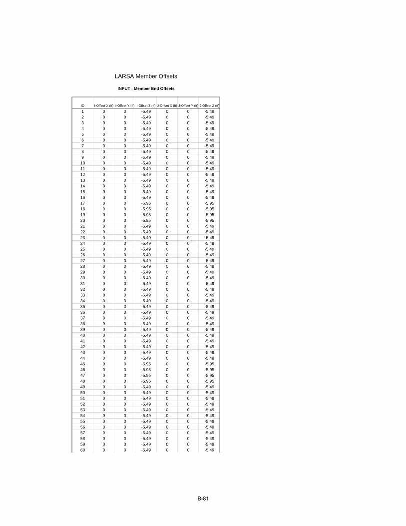
ID I-Offset X (ft) I-Offset Y (ft) I-Offset Z (ft) J-Offset X (ft) J-Offset Y (ft) J-Offset Z (ft)
1 0 0 -5.49 0 0 -5.492 0 0 -5.49 0 0 -5.493 0 0 -5.49 0 0 -5.494 0 0 -5.49 0 0 -5.495 0 0 -5.49 0 0 -5.496 0 0 -5.49 0 0 -5.497 0 0 -5.49 0 0 -5.498 0 0 -5.49 0 0 -5.499 0 0 -5.49 0 0 -5.4910 0 0 -5.49 0 0 -5.4911 0 0 -5.49 0 0 -5.4912 0 0 -5.49 0 0 -5.4913 0 0 -5.49 0 0 -5.4914 0 0 -5.49 0 0 -5.4915 0 0 -5.49 0 0 -5.4916 0 0 -5.49 0 0 -5.4917 0 0 -5.95 0 0 -5.9518 0 0 -5.95 0 0 -5.9519 0 0 -5.95 0 0 -5.9520 0 0 -5.95 0 0 -5.9521 0 0 -5.49 0 0 -5.4922 0 0 -5.49 0 0 -5.4923 0 0 -5.49 0 0 -5.4924 0 0 -5.49 0 0 -5.4925 0 0 -5.49 0 0 -5.4926 0 0 -5.49 0 0 -5.4927 0 0 -5.49 0 0 -5.4928 0 0 -5.49 0 0 -5.4929 0 0 -5.49 0 0 -5.4930 0 0 -5.49 0 0 -5.4931 0 0 -5.49 0 0 -5.4932 0 0 -5.49 0 0 -5.4933 0 0 -5.49 0 0 -5.4934 0 0 -5.49 0 0 -5.4935 0 0 -5.49 0 0 -5.4936 0 0 -5.49 0 0 -5.4937 0 0 -5.49 0 0 -5.4938 0 0 -5.49 0 0 -5.4939 0 0 -5.49 0 0 -5.4940 0 0 -5.49 0 0 -5.4941 0 0 -5.49 0 0 -5.4942 0 0 -5.49 0 0 -5.4943 0 0 -5.49 0 0 -5.4944 0 0 -5.49 0 0 -5.4945 0 0 -5.95 0 0 -5.9546 0 0 -5.95 0 0 -5.9547 0 0 -5.95 0 0 -5.9548 0 0 -5.95 0 0 -5.9549 0 0 -5.49 0 0 -5.4950 0 0 -5.49 0 0 -5.4951 0 0 -5.49 0 0 -5.4952 0 0 -5.49 0 0 -5.4953 0 0 -5.49 0 0 -5.4954 0 0 -5.49 0 0 -5.4955 0 0 -5.49 0 0 -5.4956 0 0 -5.49 0 0 -5.4957 0 0 -5.49 0 0 -5.4958 0 0 -5.49 0 0 -5.4959 0 0 -5.49 0 0 -5.4960 0 0 -5.49 0 0 -5.49
LARSA Member Offsets
INPUT : Member End Offsets
B-81
61 0 0 -5.49 0 0 -5.4962 0 0 -5.49 0 0 -5.4963 0 0 -5.49 0 0 -5.4964 0 0 -5.49 0 0 -5.4965 0 0 -4.566 0 0 -4.56666 0 0 -4.566 0 0 -4.56667 0 0 -4.566 0 0 -4.56668 0 0 -4.566 0 0 -4.56669 0 0 -4.566 0 0 -4.56670 0 0 -4.566 0 0 -4.56671 0 0 -4.566 0 0 -4.56672 0 0 -4.566 0 0 -4.56673 0 0 -4.566 0 0 -4.56674 0 0 -4.566 0 0 -4.56675 0 0 -4.566 0 0 -4.56676 0 0 -4.566 0 0 -4.56677 0 0 -4.566 0 0 -4.56678 0 0 -4.566 0 0 -4.56679 0 0 -4.566 0 0 -4.56680 0 0 -4.566 0 0 -4.56681 0 0 -4.566 0 0 -4.56682 0 0 -4.566 0 0 -4.56683 0 0 -4.566 0 0 -4.56684 0 0 -4.566 0 0 -4.56685 0 0 -4.566 0 0 -4.56686 0 0 -4.566 0 0 -4.56687 0 0 -4.566 0 0 -5.67588 0 0 -5.675 0 0 -4.56689 0 0 -4.566 0 0 -4.56690 0 0 -4.566 0 0 -4.56691 0 0 -4.566 0 0 -4.56692 0 0 -4.566 0 0 -4.56693 0 0 -4.566 0 0 -4.56694 0 0 -4.566 0 0 -4.56695 0 0 -4.566 0 0 -4.56696 0 0 -4.566 0 0 -4.56697 0 0 -4.566 0 0 -4.56698 0 0 -4.566 0 0 -4.56699 0 0 -4.566 0 0 -4.566100 0 0 -4.566 0 0 -4.566101 0 0 -4.566 0 0 -4.566102 0 0 -4.566 0 0 -4.566103 0 0 -4.566 0 0 -4.566104 0 0 -4.566 0 0 -4.566105 0 0 -4.566 0 0 -4.566106 0 0 -4.566 0 0 -4.566107 0 0 -4.566 0 0 -4.566108 0 0 -4.566 0 0 -4.566109 0 0 -4.566 0 0 -4.566110 0 0 -4.566 0 0 -4.566111 0 0 -4.566 0 0 -4.566112 0 0 -4.566 0 0 -4.566113 0 0 -4.566 0 0 -4.566114 0 0 -4.566 0 0 -4.566115 0 0 -4.566 0 0 -4.566116 0 0 -4.566 0 0 -4.566117 0 0 -4.566 0 0 -4.566118 0 0 -4.566 0 0 -4.566119 0 0 -4.566 0 0 -4.566120 0 0 -4.566 0 0 -4.566121 0 0 -4.566 0 0 -4.566122 0 0 -4.566 0 0 -4.566123 0 0 -4.566 0 0 -4.566124 0 0 -4.566 0 0 -4.566125 0 0 -4.566 0 0 -4.566126 0 0 -4.566 0 0 -4.566
B-82

127 0 0 -4.566 0 0 -4.566128 0 0 -4.566 0 0 -4.566129 0 0 0 0 0 0130 0 0 0 0 0 0131 0 0 0 0 0 0132 0 0 -5.918 0 0 -5.918133 0 0 -5.918 0 0 -5.918134 0 0 -5.918 0 0 -5.918135 0 0 -5.918 0 0 -5.918136 0 0 -5.918 0 0 -5.918137 0 0 -5.918 0 0 -5.918138 0 0 -5.918 0 0 -5.918139 0 0 -5.918 0 0 -5.918140 0 0 0 0 0 0141 0 0 0 0 0 0142 0 0 0 0 0 0143 0 0 -4.566 0 0 -5.675144 0 0 -5.675 0 0 -4.566145 0 0 -6.151 0 0 -6.151146 0 0 -6.151 0 0 -6.151147 0 0 -4.566 0 0 -5.675148 0 0 -5.675 0 0 -4.566149 0 0 -4.566 0 0 -5.675150 0 0 -5.675 0 0 -4.566151 0 0 -6.151 0 0 -6.151152 0 0 -6.151 0 0 -6.151153 0 0 -5.27 0 0 -5.27154 0 0 -5.27 0 0 -5.27155 0 0 -5.27 0 0 -5.27156 0 0 -5.27 0 0 -5.27157 0 0 -5.27 0 0 -5.27158 0 0 -5.27 0 0 -5.27159 0 0 -5.27 0 0 -5.27160 0 0 -5.27 0 0 -5.27161 0 0 -5.27 0 0 -5.27162 0 0 -5.27 0 0 -6.83163 0 0 -6.83 0 0 -5.27164 0 0 -5.27 0 0 -5.27165 0 0 -5.27 0 0 -5.27166 0 0 -5.27 0 0 -5.27167 0 0 -5.27 0 0 -5.27168 0 0 -5.27 0 0 -5.27169 0 0 -5.27 0 0 -5.27170 0 0 -5.27 0 0 -5.27171 0 0 -5.27 0 0 -5.27172 0 0 -5.27 0 0 -5.27173 0 0 -5.27 0 0 -5.27174 0 0 -5.27 0 0 -5.27175 0 0 -5.27 0 0 -5.27176 0 0 -5.27 0 0 -5.27177 0 0 -5.27 0 0 -6.83178 0 0 -6.83 0 0 -5.27179 0 0 -5.27 0 0 -5.27180 0 0 -5.27 0 0 -5.27181 0 0 -5.27 0 0 -5.27182 0 0 -5.27 0 0 -5.27183 0 0 -5.27 0 0 -5.27184 0 0 -5.27 0 0 -5.27185 0 0 -5.27 0 0 -5.27186 0 0 -5.27 0 0 -5.27187 0 0 -5.27 0 0 -5.27188 0 0 0 0 0 0189 0 0 0 0 0 0190 0 0 0 0 0 0191 0 0 0 0 0 0
B-83

Tendon Name Material Exposure Strand Area (per strand) (ft²) # of Strands Proposed Jacking
Force (kips) Jacking End Anchor Set (ft) Wobble Coefficient (per ft)
Curvature Friction Coefficient
Elongation After Pull 1
Elongation After Pull 2
TMIDF PSS Internal 0.0015 124 4912 Start, then End 0.0328 0.0002 0.15 3.6191 0.4152TOUTF PSS Internal 0.0015 124 4912 Start, then End 0.0328 0.0002 0.15 3.7115 0.4427
TINF PSS Internal 0.0015 124 4912 Start, then End 0.0328 0.0002 0.15 3.4945 0.4044
Point Type Reference Object Type
Reference Object or Range Offset X (ft) Offset Y (ft) Offset Z (ft) X Reference Y Reference Z Reference Curvature Type
geometry member 153 0 0 -6 Start Reference Line +Z1 Local Edge No Curvegeometry member 154 0 0 -7.53 Start Reference Line +Z1 Local Edge No Curvegeometry member 155 0 0 -8.63 Start Reference Line +Z1 Local Edge No Curvegeometry member 156 0 0 -9.28 Start Reference Line +Z1 Local Edge No Curvegeometry member 157 0 0 -9.5 Start Reference Line +Z1 Local Edge No Curvegeometry member 158 0 0 -9.24 Start Reference Line +Z1 Local Edge No Curvegeometry member 159 0 0 -8.466 Start Reference Line +Z1 Local Edge No Curvegeometry member 160 0 0 -7.174 Start Reference Line +Z1 Local Edge No Curvegeometry member 161 0 0 -5.366 Start Reference Line +Z1 Local Edge No Curvegeometry member 162 0 0 -3.04 Start Reference Line +Z1 Local Edge No Curvegeometry member 163 0 0 -1.75 Start Reference Line +Z1 Local Edge No Curvegeometry member 164 0 0 -2.513 Start Reference Line +Z1 Local Edge No Curvegeometry member 165 0 0 -4.4814 Start Reference Line +Z1 Local Edge No Curvegeometry member 166 0 0 -6.2685 Start Reference Line +Z1 Local Edge No Curvegeometry member 167 0 0 -7.7306 Start Reference Line +Z1 Local Edge No Curvegeometry member 168 0 0 -8.8678 Start Reference Line +Z1 Local Edge No Curvegeometry member 169 0 0 -9.68 Start Reference Line +Z1 Local Edge No Curvegeometry member 170 0 0 -10.168 Start Reference Line +Z1 Local Edge No Curvegeometry member 170 10 0 -10.33 Start Reference Line +Z1 Local Edge No Curvegeometry member 171 0 0 -10.168 Start Reference Line +Z1 Local Edge No Curvegeometry member 172 0 0 -9.68 Start Reference Line +Z1 Local Edge No Curvegeometry member 173 0 0 -8.8678 Start Reference Line +Z1 Local Edge No Curvegeometry member 174 0 0 -7.7306 Start Reference Line +Z1 Local Edge No Curvegeometry member 175 0 0 -6.285 Start Reference Line +Z1 Local Edge No Curvegeometry member 176 0 0 -4.4814 Start Reference Line +Z1 Local Edge No Curvegeometry member 177 0 0 -2.513 Start Reference Line +Z1 Local Edge No Curvegeometry member 178 0 0 -1.75 Start Reference Line +Z1 Local Edge No Curvegeometry member 179 0 0 -3.04 Start Reference Line +Z1 Local Edge No Curvegeometry member 180 0 0 -5.366 Start Reference Line +Z1 Local Edge No Curvegeometry member 181 0 0 -7.174 Start Reference Line +Z1 Local Edge No Curvegeometry member 182 0 0 -8.466 Start Reference Line +Z1 Local Edge No Curvegeometry member 183 0 0 -9.24 Start Reference Line +Z1 Local Edge No Curvegeometry member 184 0 0 -9.5 Start Reference Line +Z1 Local Edge No Curvegeometry member 185 0 0 -9.28 Start Reference Line +Z1 Local Edge No Curvegeometry member 186 0 0 -8.63 Start Reference Line +Z1 Local Edge No Curvegeometry member 187 0 0 -7.73 Start Reference Line +Z1 Local Edge No Curvegeometry member 187 0 0 -6 End Reference Line +Z1 Local Edge No Curve
INPUT : Tendons
TENDON TMIDF
LARSA Prestress Tendon Input
B-84
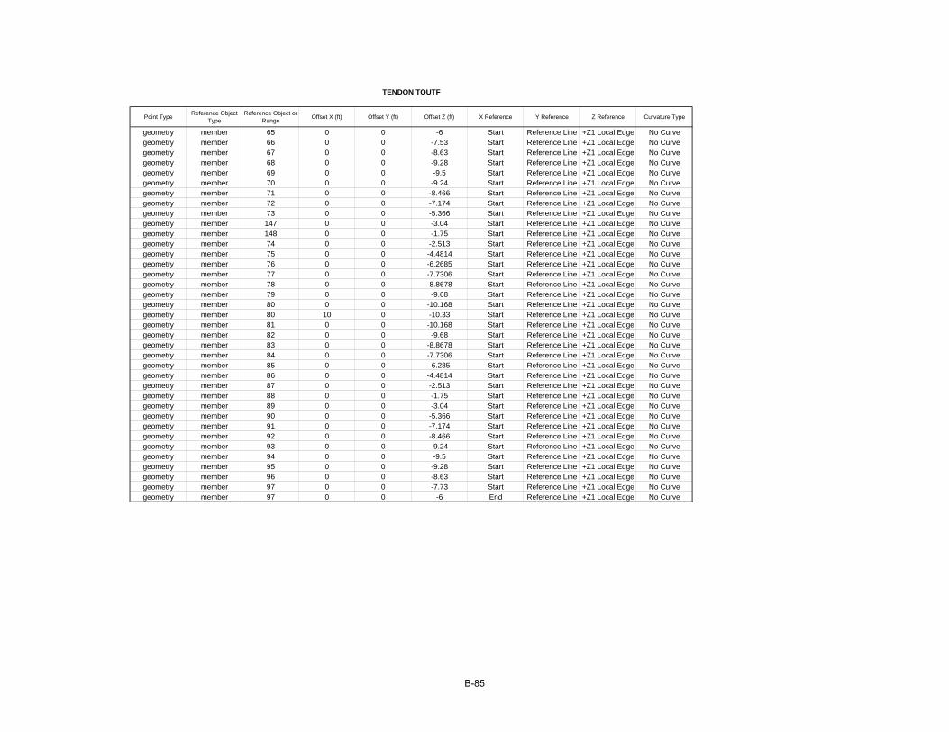
Point Type Reference Object Type
Reference Object or Range Offset X (ft) Offset Y (ft) Offset Z (ft) X Reference Y Reference Z Reference Curvature Type
geometry member 65 0 0 -6 Start Reference Line +Z1 Local Edge No Curvegeometry member 66 0 0 -7.53 Start Reference Line +Z1 Local Edge No Curvegeometry member 67 0 0 -8.63 Start Reference Line +Z1 Local Edge No Curvegeometry member 68 0 0 -9.28 Start Reference Line +Z1 Local Edge No Curvegeometry member 69 0 0 -9.5 Start Reference Line +Z1 Local Edge No Curvegeometry member 70 0 0 -9.24 Start Reference Line +Z1 Local Edge No Curvegeometry member 71 0 0 -8.466 Start Reference Line +Z1 Local Edge No Curvegeometry member 72 0 0 -7.174 Start Reference Line +Z1 Local Edge No Curvegeometry member 73 0 0 -5.366 Start Reference Line +Z1 Local Edge No Curvegeometry member 147 0 0 -3.04 Start Reference Line +Z1 Local Edge No Curvegeometry member 148 0 0 -1.75 Start Reference Line +Z1 Local Edge No Curvegeometry member 74 0 0 -2.513 Start Reference Line +Z1 Local Edge No Curvegeometry member 75 0 0 -4.4814 Start Reference Line +Z1 Local Edge No Curvegeometry member 76 0 0 -6.2685 Start Reference Line +Z1 Local Edge No Curvegeometry member 77 0 0 -7.7306 Start Reference Line +Z1 Local Edge No Curvegeometry member 78 0 0 -8.8678 Start Reference Line +Z1 Local Edge No Curvegeometry member 79 0 0 -9.68 Start Reference Line +Z1 Local Edge No Curvegeometry member 80 0 0 -10.168 Start Reference Line +Z1 Local Edge No Curvegeometry member 80 10 0 -10.33 Start Reference Line +Z1 Local Edge No Curvegeometry member 81 0 0 -10.168 Start Reference Line +Z1 Local Edge No Curvegeometry member 82 0 0 -9.68 Start Reference Line +Z1 Local Edge No Curvegeometry member 83 0 0 -8.8678 Start Reference Line +Z1 Local Edge No Curvegeometry member 84 0 0 -7.7306 Start Reference Line +Z1 Local Edge No Curvegeometry member 85 0 0 -6.285 Start Reference Line +Z1 Local Edge No Curvegeometry member 86 0 0 -4.4814 Start Reference Line +Z1 Local Edge No Curvegeometry member 87 0 0 -2.513 Start Reference Line +Z1 Local Edge No Curvegeometry member 88 0 0 -1.75 Start Reference Line +Z1 Local Edge No Curvegeometry member 89 0 0 -3.04 Start Reference Line +Z1 Local Edge No Curvegeometry member 90 0 0 -5.366 Start Reference Line +Z1 Local Edge No Curvegeometry member 91 0 0 -7.174 Start Reference Line +Z1 Local Edge No Curvegeometry member 92 0 0 -8.466 Start Reference Line +Z1 Local Edge No Curvegeometry member 93 0 0 -9.24 Start Reference Line +Z1 Local Edge No Curvegeometry member 94 0 0 -9.5 Start Reference Line +Z1 Local Edge No Curvegeometry member 95 0 0 -9.28 Start Reference Line +Z1 Local Edge No Curvegeometry member 96 0 0 -8.63 Start Reference Line +Z1 Local Edge No Curvegeometry member 97 0 0 -7.73 Start Reference Line +Z1 Local Edge No Curvegeometry member 97 0 0 -6 End Reference Line +Z1 Local Edge No Curve
TENDON TOUTF
B-85
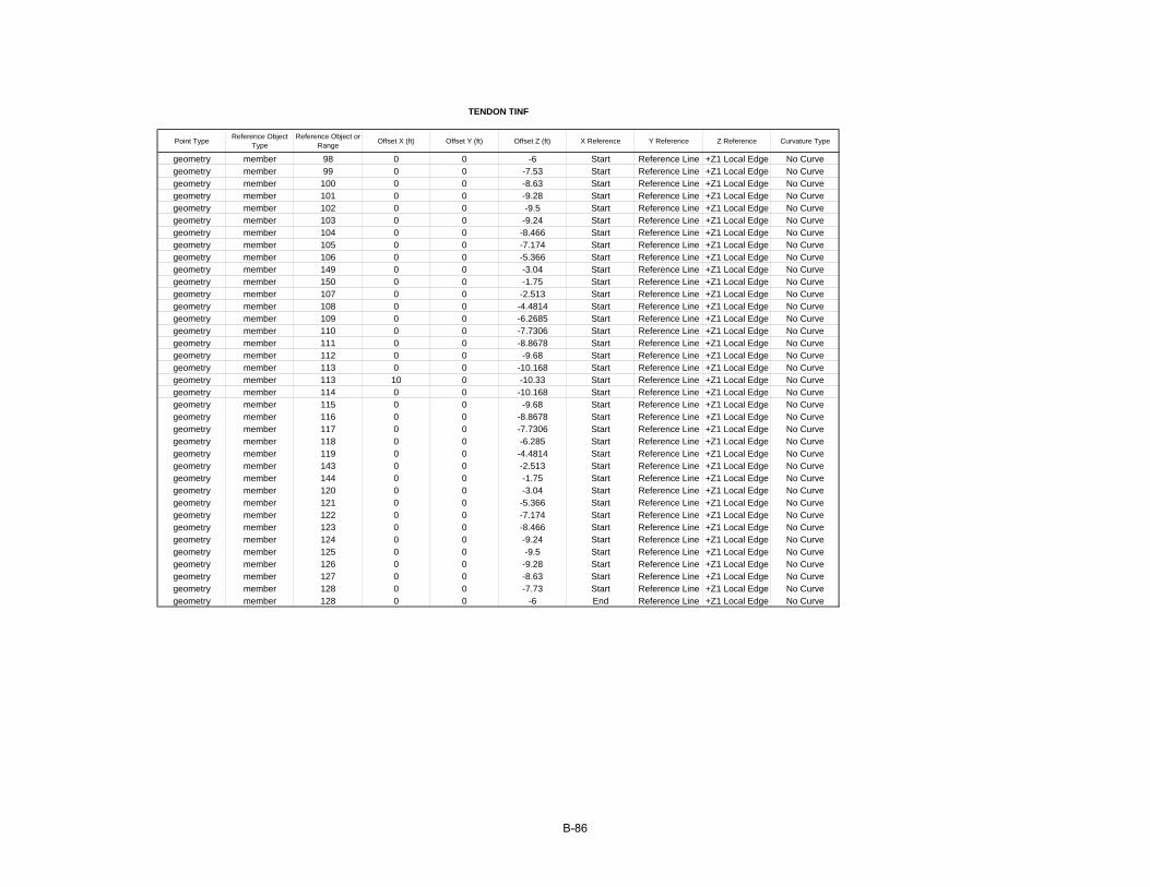
Point Type Reference Object Type
Reference Object or Range Offset X (ft) Offset Y (ft) Offset Z (ft) X Reference Y Reference Z Reference Curvature Type
geometry member 98 0 0 -6 Start Reference Line +Z1 Local Edge No Curvegeometry member 99 0 0 -7.53 Start Reference Line +Z1 Local Edge No Curvegeometry member 100 0 0 -8.63 Start Reference Line +Z1 Local Edge No Curvegeometry member 101 0 0 -9.28 Start Reference Line +Z1 Local Edge No Curvegeometry member 102 0 0 -9.5 Start Reference Line +Z1 Local Edge No Curvegeometry member 103 0 0 -9.24 Start Reference Line +Z1 Local Edge No Curvegeometry member 104 0 0 -8.466 Start Reference Line +Z1 Local Edge No Curvegeometry member 105 0 0 -7.174 Start Reference Line +Z1 Local Edge No Curvegeometry member 106 0 0 -5.366 Start Reference Line +Z1 Local Edge No Curvegeometry member 149 0 0 -3.04 Start Reference Line +Z1 Local Edge No Curvegeometry member 150 0 0 -1.75 Start Reference Line +Z1 Local Edge No Curvegeometry member 107 0 0 -2.513 Start Reference Line +Z1 Local Edge No Curvegeometry member 108 0 0 -4.4814 Start Reference Line +Z1 Local Edge No Curvegeometry member 109 0 0 -6.2685 Start Reference Line +Z1 Local Edge No Curvegeometry member 110 0 0 -7.7306 Start Reference Line +Z1 Local Edge No Curvegeometry member 111 0 0 -8.8678 Start Reference Line +Z1 Local Edge No Curvegeometry member 112 0 0 -9.68 Start Reference Line +Z1 Local Edge No Curvegeometry member 113 0 0 -10.168 Start Reference Line +Z1 Local Edge No Curvegeometry member 113 10 0 -10.33 Start Reference Line +Z1 Local Edge No Curvegeometry member 114 0 0 -10.168 Start Reference Line +Z1 Local Edge No Curvegeometry member 115 0 0 -9.68 Start Reference Line +Z1 Local Edge No Curvegeometry member 116 0 0 -8.8678 Start Reference Line +Z1 Local Edge No Curvegeometry member 117 0 0 -7.7306 Start Reference Line +Z1 Local Edge No Curvegeometry member 118 0 0 -6.285 Start Reference Line +Z1 Local Edge No Curvegeometry member 119 0 0 -4.4814 Start Reference Line +Z1 Local Edge No Curvegeometry member 143 0 0 -2.513 Start Reference Line +Z1 Local Edge No Curvegeometry member 144 0 0 -1.75 Start Reference Line +Z1 Local Edge No Curvegeometry member 120 0 0 -3.04 Start Reference Line +Z1 Local Edge No Curvegeometry member 121 0 0 -5.366 Start Reference Line +Z1 Local Edge No Curvegeometry member 122 0 0 -7.174 Start Reference Line +Z1 Local Edge No Curvegeometry member 123 0 0 -8.466 Start Reference Line +Z1 Local Edge No Curvegeometry member 124 0 0 -9.24 Start Reference Line +Z1 Local Edge No Curvegeometry member 125 0 0 -9.5 Start Reference Line +Z1 Local Edge No Curvegeometry member 126 0 0 -9.28 Start Reference Line +Z1 Local Edge No Curvegeometry member 127 0 0 -8.63 Start Reference Line +Z1 Local Edge No Curvegeometry member 128 0 0 -7.73 Start Reference Line +Z1 Local Edge No Curvegeometry member 128 0 0 -6 End Reference Line +Z1 Local Edge No Curve
TENDON TINF
B-86
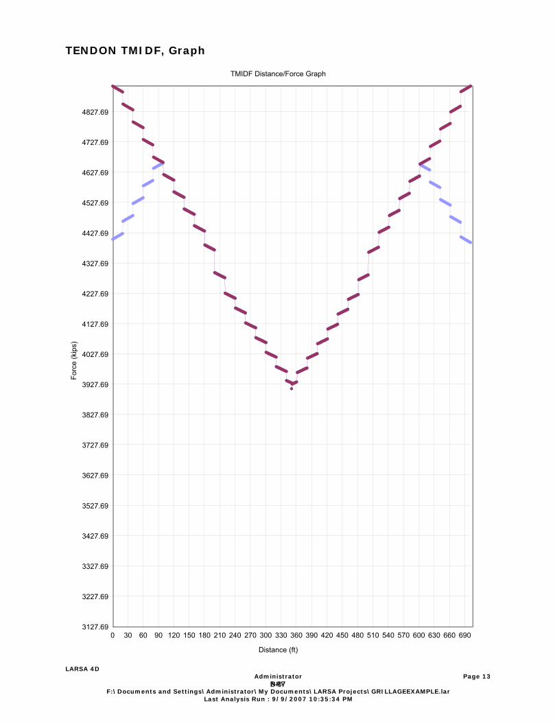
3127.69
3227.69
3327.69
3427.69
3527.69
3627.69
3727.69
3827.69
3927.69
4027.69
4127.69
4227.69
4327.69
4427.69
4527.69
4627.69
4727.69
4827.69
0 30 60 90 120 150 180 210 240 270 300 330 360 390 420 450 480 510 540 570 600 630 660 690
Forc
e (k
ips)
TMIDF Distance/Force GraphTMIDF Distance/Force Graph
Distance (ft)
TENDON TMIDF, Graph
LARSA 4D Administrator
NRVF:\Documents and Settings\Administrator\My Documents\LARSA Projects\GRILLAGEEXAMPLE.lar
Last Analysis Run : 9/9/2007 10:35:34 PM
Page 13
B-87
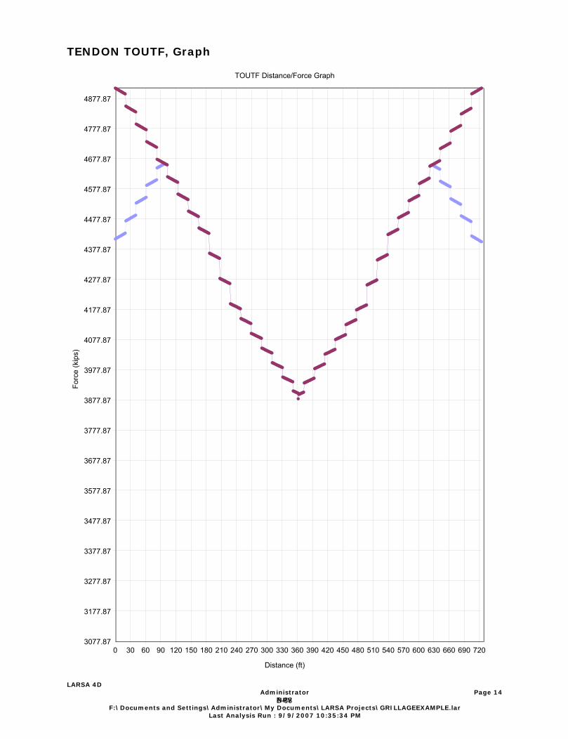
3077.87
3177.87
3277.87
3377.87
3477.87
3577.87
3677.87
3777.87
3877.87
3977.87
4077.87
4177.87
4277.87
4377.87
4477.87
4577.87
4677.87
4777.87
4877.87
0 30 60 90 120 150 180 210 240 270 300 330 360 390 420 450 480 510 540 570 600 630 660 690 720
Forc
e (k
ips)
TOUTF Distance/Force GraphTOUTF Distance/Force Graph
Distance (ft)
TENDON TOUTF, Graph
LARSA 4D Administrator
NRVF:\Documents and Settings\Administrator\My Documents\LARSA Projects\GRILLAGEEXAMPLE.lar
Last Analysis Run : 9/9/2007 10:35:34 PM
Page 14
B-88

3117.44
3217.44
3317.44
3417.44
3517.44
3617.44
3717.44
3817.44
3917.44
4017.44
4117.44
4217.44
4317.44
4417.44
4517.44
4617.44
4717.44
4817.44
0 30 60 90 120 150 180 210 240 270 300 330 360 390 420 450 480 510 540 570 600 630 660
Forc
e (k
ips)
TINF Distance/Force GraphTINF Distance/Force Graph
Distance (ft)
TENDON TINF, Graph
LARSA 4D Administrator
NRVF:\Documents and Settings\Administrator\My Documents\LARSA Projects\GRILLAGEEXAMPLE.lar
Last Analysis Run : 9/9/2007 10:35:34 PM
Page 15
B-89
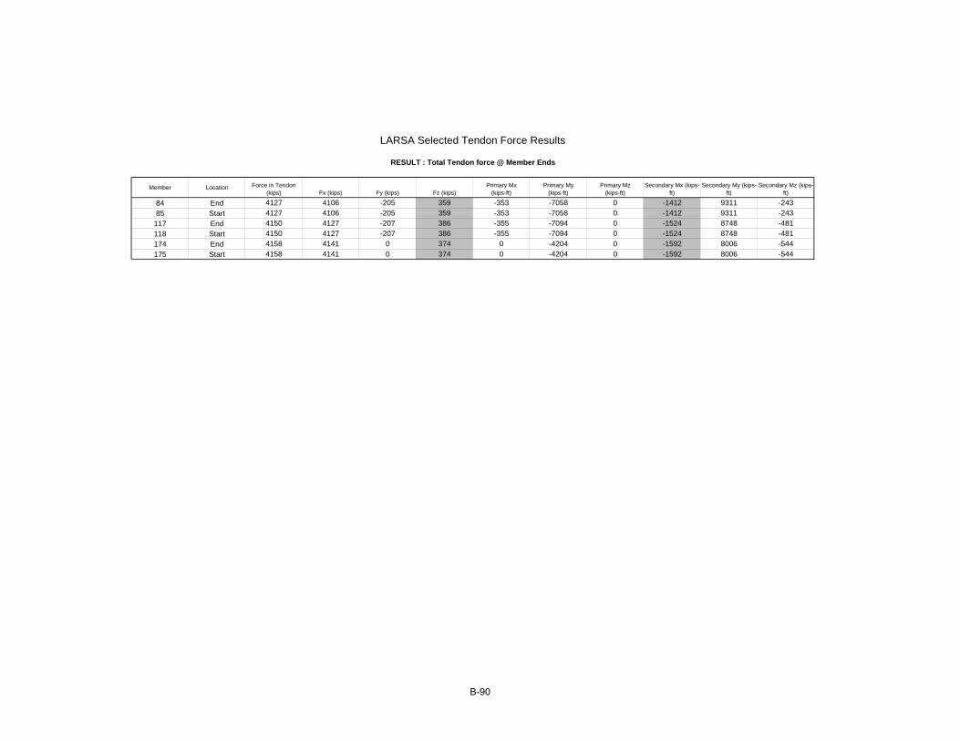
Member Location Force in Tendon (kips) Fx (kips) Fy (kips) Fz (kips)
Primary Mx (kips-ft)
Primary My (kips-ft)
Primary Mz (kips-ft)
Secondary Mx (kips-ft)
Secondary My (kips-ft)
Secondary Mz (kips-ft)
84 End 4127 4106 -205 359 -353 -7058 0 -1412 9311 -24385 Start 4127 4106 -205 359 -353 -7058 0 -1412 9311 -243
117 End 4150 4127 -207 386 -355 -7094 0 -1524 8748 -481118 Start 4150 4127 -207 386 -355 -7094 0 -1524 8748 -481174 End 4158 4141 0 374 0 -4204 0 -1592 8006 -544175 Start 4158 4141 0 374 0 -4204 0 -1592 8006 -544
RESULT : Total Tendon force @ Member Ends
LARSA Selected Tendon Force Results
B-90
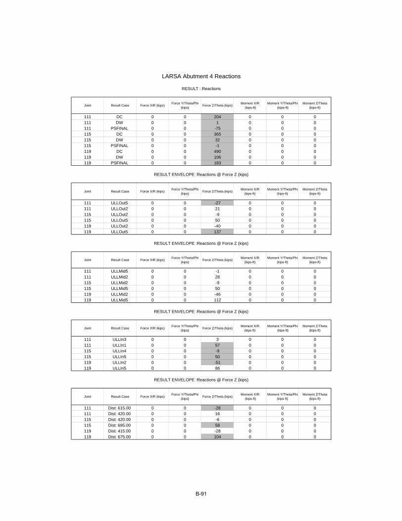
Joint Result Case Force X/R (kips) Force Y/Theta/Phi (kips) Force Z/Theta (kips) Moment X/R
(kips-ft)Moment Y/Theta/Phi
(kips-ft)Moment Z/Theta
(kips-ft)
111 DC 0 0 204 0 0 0111 DW 0 0 1 0 0 0111 PSFINAL 0 0 -75 0 0 0115 DC 0 0 365 0 0 0115 DW 0 0 32 0 0 0115 PSFINAL 0 0 -1 0 0 0119 DC 0 0 490 0 0 0119 DW 0 0 106 0 0 0119 PSFINAL 0 0 183 0 0 0
Joint Result Case Force X/R (kips) Force Y/Theta/Phi (kips) Force Z/Theta (kips) Moment X/R
(kips-ft)Moment Y/Theta/Phi
(kips-ft)Moment Z/Theta
(kips-ft)
111 ULLOut5 0 0 -27 0 0 0111 ULLOut2 0 0 21 0 0 0115 ULLOut2 0 0 -9 0 0 0115 ULLOut5 0 0 50 0 0 0119 ULLOut2 0 0 -40 0 0 0119 ULLOut5 0 0 137 0 0 0
Joint Result Case Force X/R (kips) Force Y/Theta/Phi (kips) Force Z/Theta (kips) Moment X/R
(kips-ft)Moment Y/Theta/Phi
(kips-ft)Moment Z/Theta
(kips-ft)
111 ULLMid5 0 0 -1 0 0 0111 ULLMid2 0 0 28 0 0 0115 ULLMid2 0 0 -9 0 0 0115 ULLMid5 0 0 50 0 0 0119 ULLMid2 0 0 -46 0 0 0119 ULLMid5 0 0 112 0 0 0
Joint Result Case Force X/R (kips) Force Y/Theta/Phi (kips) Force Z/Theta (kips) Moment X/R
(kips-ft)Moment Y/Theta/Phi
(kips-ft)Moment Z/Theta
(kips-ft)
111 ULLIn3 0 0 3 0 0 0111 ULLIn1 0 0 57 0 0 0115 ULLIn4 0 0 -9 0 0 0115 ULLIn5 0 0 50 0 0 0119 ULLIn2 0 0 -51 0 0 0119 ULLIn5 0 0 86 0 0 0
Joint Result Case Force X/R (kips) Force Y/Theta/Phi (kips) Force Z/Theta (kips) Moment X/R
(kips-ft)Moment Y/Theta/Phi
(kips-ft)Moment Z/Theta
(kips-ft)
111 Dist: 615.00 0 0 -28 0 0 0111 Dist: 420.00 0 0 16 0 0 0115 Dist: 420.00 0 0 -6 0 0 0115 Dist: 695.00 0 0 58 0 0 0119 Dist: 415.00 0 0 -28 0 0 0119 Dist: 675.00 0 0 104 0 0 0
RESULT ENVELOPE :Reactions @ Force Z (kips)
RESULT ENVELOPE :Reactions @ Force Z (kips)
LARSA Abutment 4 Reactions
RESULT : Reactions
RESULT ENVELOPE :Reactions @ Force Z (kips)
RESULT ENVELOPE :Reactions @ Force Z (kips)
B-91
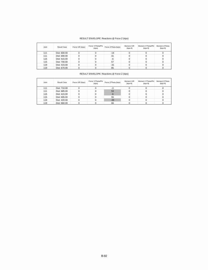
Joint Result Case Force X/R (kips) Force Y/Theta/Phi (kips) Force Z/Theta (kips) Moment X/R
(kips-ft)Moment Y/Theta/Phi
(kips-ft)Moment Z/Theta
(kips-ft)
111 Dist: 600.00 0 0 -14 0 0 0111 Dist: 690.00 0 0 31 0 0 0115 Dist: 415.00 0 0 -6 0 0 0115 Dist: 700.00 0 0 57 0 0 0119 Dist: 415.00 0 0 -31 0 0 0119 Dist: 670.00 0 0 85 0 0 0
Joint Result Case Force X/R (kips) Force Y/Theta/Phi (kips) Force Z/Theta (kips) Moment X/R
(kips-ft)Moment Y/Theta/Phi
(kips-ft)Moment Z/Theta
(kips-ft)
111 Dist: 710.00 0 0 -3 0 0 0111 Dist: 685.00 0 0 53 0 0 0115 Dist: 415.00 0 0 -6 0 0 0115 Dist: 695.00 0 0 55 0 0 0119 Dist: 420.00 0 0 -33 0 0 0119 Dist: 660.00 0 0 66 0 0 0
RESULT ENVELOPE :Reactions @ Force Z (kips)
RESULT ENVELOPE :Reactions @ Force Z (kips)
B-92

Member Joint Result Case Force X (kips) Force Y (kips) Force Z (kips) Moment X (kips-ft) Moment Y (kips-ft) Moment Z (kips-ft)
80 12 DC -4 0 42 -4 14846 25780 11 DC 4 0 42 4 -14839 -25884 25 DC -72 9 -309 -2226 6281 28184 31 DC 72 -9 393 2226 965 -8785 31 DC -109 11 -390 -2143 338 25585 35 DC 109 -11 474 2143 8588 -2787 41 DC -204 9 -557 952 -15775 187 50 DC 199 -9 648 -952 28237 189113 2 DC 593 0 39 -4 15642 252113 1 DC -593 0 40 4 -15638 -252117 17 DC 336 39 -245 -2459 5453 548117 23 DC -336 -39 324 2459 47 198118 23 DC 193 47 -319 -2472 -1047 588118 29 DC -193 -47 398 2472 7979 323143 37 DC -165 61 -478 -2835 -17112 492143 44 DC 160 -61 563 2835 27205 683170 6 DC -241 0 47 -4 20668 303170 5 DC 241 0 49 4 -20649 -303174 21 DC 77 21 -352 -2355 7637 427174 27 DC -77 -21 447 2355 349 -3175 27 DC 253 28 -455 -2325 -876 445175 33 DC -253 -28 550 2325 10920 114177 39 DC 804 49 -607 -926 -25711 341177 45 DC -813 -49 722 926 39038 634
Member Joint Result Case Force X (kips) Force Y (kips) Force Z (kips) Moment X (kips-ft) Moment Y (kips-ft) Moment Z (kips-ft)
80 12 DW -1 0 10 46 2869 5080 11 DW 1 0 10 42 -2874 -5084 25 DW -14 2 -62 -396 1279 5684 31 DW 14 -2 83 483 217 -1685 31 DW -20 2 -80 -383 152 5185 35 DW 20 -2 100 470 1708 -387 41 DW -35 2 -117 215 -2968 487 50 DW 34 -2 138 -128 5608 38113 2 DW 116 0 10 -39 3027 49113 1 DW -116 0 9 -43 -3031 -49117 17 DW 66 7 -49 -525 1113 106117 23 DW -66 -7 68 443 26 38118 23 DW 39 9 -65 -530 -125 114118 29 DW -39 -9 84 448 1573 61143 37 DW -27 12 -101 -606 -3217 91143 44 DW 26 -12 120 524 5357 134170 6 DW -47 0 6 2 4010 59170 5 DW 47 0 5 -2 -4014 -59174 21 DW 14 4 -63 -466 1419 83174 27 DW -14 -4 74 466 -51 -1175 27 DW 47 5 -80 -464 -266 87175 33 DW -47 -5 90 464 1963 22177 39 DW 146 9 -99 -205 -5080 64177 45 DW -147 -9 110 205 7179 125
LARSA Member Forces Results for Grillage Analysis
RESULT : Member End Forces (Local)
RESULT : Member End Forces (Local)
B-93
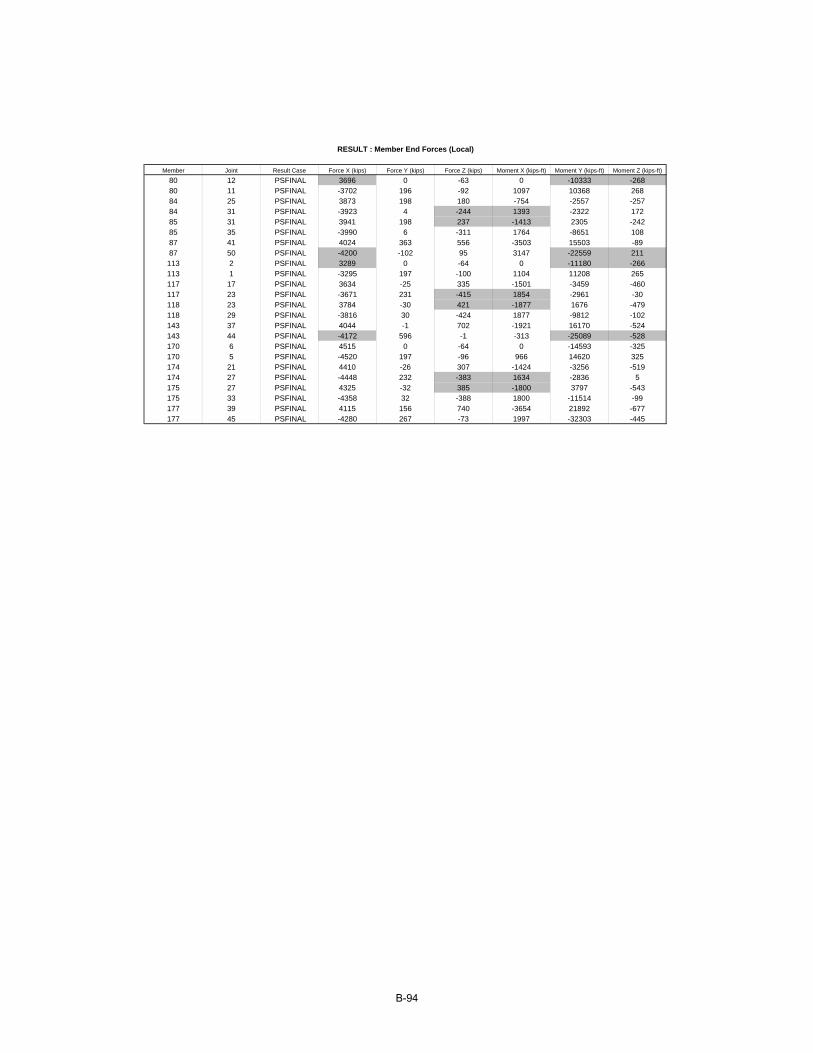
Member Joint Result Case Force X (kips) Force Y (kips) Force Z (kips) Moment X (kips-ft) Moment Y (kips-ft) Moment Z (kips-ft)
80 12 PSFINAL 3696 0 -63 0 -10333 -26880 11 PSFINAL -3702 196 -92 1097 10368 26884 25 PSFINAL 3873 198 180 -754 -2557 -25784 31 PSFINAL -3923 4 -244 1393 -2322 17285 31 PSFINAL 3941 198 237 -1413 2305 -24285 35 PSFINAL -3990 6 -311 1764 -8651 10887 41 PSFINAL 4024 363 556 -3503 15503 -8987 50 PSFINAL -4200 -102 95 3147 -22559 211113 2 PSFINAL 3289 0 -64 0 -11180 -266113 1 PSFINAL -3295 197 -100 1104 11208 265117 17 PSFINAL 3634 -25 335 -1501 -3459 -460117 23 PSFINAL -3671 231 -415 1854 -2961 -30118 23 PSFINAL 3784 -30 421 -1877 1676 -479118 29 PSFINAL -3816 30 -424 1877 -9812 -102143 37 PSFINAL 4044 -1 702 -1921 16170 -524143 44 PSFINAL -4172 596 -1 -313 -25089 -528170 6 PSFINAL 4515 0 -64 0 -14593 -325170 5 PSFINAL -4520 197 -96 966 14620 325174 21 PSFINAL 4410 -26 307 -1424 -3256 -519174 27 PSFINAL -4448 232 -383 1634 -2836 5175 27 PSFINAL 4325 -32 385 -1800 3797 -543175 33 PSFINAL -4358 32 -388 1800 -11514 -99177 39 PSFINAL 4115 156 740 -3654 21892 -677177 45 PSFINAL -4280 267 -73 1997 -32303 -445
RESULT : Member End Forces (Local)
B-94

Member Joint Result Case Force X (kips) Force Y (kips) Force Z (kips) Moment X (kips-ft) Moment Y (kips-ft) Moment Z (kips-ft)
80 12 ULLOut5 49 0 0 1 -547 -7480 12 ULLOut2 -22 0 10 -5 2399 7280 11 ULLOut3 -24 0 -4 15 237 3980 11 ULLOut1 -3 0 7 9 -2162 -3484 25 ULLOut4� -31 7 -49 -526 1459 14784 25 ULLOut3 16 -3 4 -7 115 -5284 31 ULLOut3 -16 3 -4 7 -188 -284 31 ULLOut4� 31 -7 63 544 -300 -485 31 ULLOut4� -22 9 -62 -568 578 14585 31 ULLOut3 10 -3 3 -19 222 -5385 35 ULLOut3 -10 3 -3 19 -290 -1585 35 ULLOut4� 22 -9 75 587 844 3187 41 ULLOut1 -31 1 -88 -13 -2387 -687 41 ULLOut3 -5 -4 2 -69 350 -3487 50 ULLOut3 5 4 -2 69 -398 -4587 50 ULLOut1 30 -1 101 32 4340 31113 2 ULLOut5 -131 0 0 1 -572 -80113 2 ULLOut2 144 0 15 8 2471 69113 1 ULLOut3 65 0 -8 18 204 37113 1 ULLOut1 -79 0 6 25 -2267 -32117 17 ULLOut1 43 5 -34 -450 730 75117 17 ULLOut3 -45 -4 7 -8 93 -62117 23 ULLOut3 45 4 -7 8 -234 -7117 23 ULLOut1 -43 -5 47 501 53 30118 23 ULLOut1 23 7 -45 -481 -243 81118 23 ULLOut3 -35 -4 7 -20 205 -62118 29 ULLOut3 35 4 -7 20 -342 -22118 29 ULLOut1 -23 -7 58 531 1236 47143 37 ULLOut1 -28 9 -69 -573 -2625 64143 37 ULLOut3 -11 -6 6 -34 354 -44143 44 ULLOut3 11 6 -6 34 -468 -67143 44 ULLOut1 27 -9 82 624 4088 101170 6 ULLOut5 -22 0 0 1 -761 -93170 6 ULLOut2 -26 0 13 2 3319 84170 5 ULLOut3 11 0 -7 16 315 45170 5 ULLOut1 37 0 6 18 -3004 -39174 21 ULLOut4� 33 11 -54 -545 1815 197174 21 ULLOut3 -22 -4 8 -7 134 -75174 27 ULLOut3 22 4 -8 7 -290 -11174 27 ULLOut4� -33 -11 67 580 -609 14175 27 ULLOut4� 59 13 -70 -597 529 203175 27 ULLOut3 -25 -5 8 -19 280 -77175 33 ULLOut3 25 5 -8 19 -445 -30175 33 ULLOut4� -59 -13 82 632 991 64177 39 ULLOut4� 142 20 -91 -553 -3619 131177 39 ULLOut3 -34 -8 7 -68 725 -69177 45 ULLOut3 34 8 -7 68 -864 -95177 45 ULLOut4� -143 -20 104 588 5580 279
RESULT ENVELOPE :Member End Forces (Local) @ Force Z (kips)
B-95
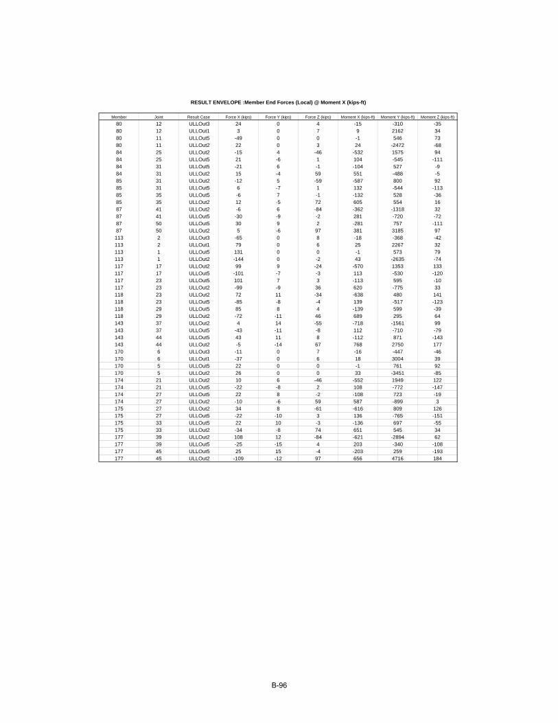
Member Joint Result Case Force X (kips) Force Y (kips) Force Z (kips) Moment X (kips-ft) Moment Y (kips-ft) Moment Z (kips-ft)
80 12 ULLOut3 24 0 4 -15 -310 -3580 12 ULLOut1 3 0 7 9 2162 3480 11 ULLOut5 -49 0 0 -1 546 7380 11 ULLOut2 22 0 3 24 -2472 -6884 25 ULLOut2 -15 4 -46 -532 1575 9484 25 ULLOut5 21 -6 1 104 -545 -11184 31 ULLOut5 -21 6 -1 -104 527 -984 31 ULLOut2 15 -4 59 551 -488 -585 31 ULLOut2 -12 5 -59 -587 800 9285 31 ULLOut5 6 -7 1 132 -544 -11385 35 ULLOut5 -6 7 -1 -132 528 -3685 35 ULLOut2 12 -5 72 605 554 1687 41 ULLOut2 -6 6 -84 -362 -1318 3287 41 ULLOut5 -30 -9 -2 281 -720 -7287 50 ULLOut5 30 9 2 -281 757 -11187 50 ULLOut2 5 -6 97 381 3185 97113 2 ULLOut3 -65 0 8 -18 -368 -42113 2 ULLOut1 79 0 6 25 2267 32113 1 ULLOut5 131 0 0 -1 573 79113 1 ULLOut2 -144 0 -2 43 -2635 -74117 17 ULLOut2 99 9 -24 -570 1353 133117 17 ULLOut5 -101 -7 -3 113 -530 -120117 23 ULLOut5 101 7 3 -113 595 -10117 23 ULLOut2 -99 -9 36 620 -775 33118 23 ULLOut2 72 11 -34 -638 480 141118 23 ULLOut5 -85 -8 -4 139 -517 -123118 29 ULLOut5 85 8 4 -139 599 -39118 29 ULLOut2 -72 -11 46 689 295 64143 37 ULLOut2 4 14 -55 -718 -1561 99143 37 ULLOut5 -43 -11 -8 112 -710 -79143 44 ULLOut5 43 11 8 -112 871 -143143 44 ULLOut2 -5 -14 67 768 2750 177170 6 ULLOut3 -11 0 7 -16 -447 -46170 6 ULLOut1 -37 0 6 18 3004 39170 5 ULLOut5 22 0 0 -1 761 92170 5 ULLOut2 26 0 0 33 -3451 -85174 21 ULLOut2 10 6 -46 -552 1949 122174 21 ULLOut5 -22 -8 2 108 -772 -147174 27 ULLOut5 22 8 -2 -108 723 -19174 27 ULLOut2 -10 -6 59 587 -899 3175 27 ULLOut2 34 8 -61 -616 809 126175 27 ULLOut5 -22 -10 3 136 -765 -151175 33 ULLOut5 22 10 -3 -136 697 -55175 33 ULLOut2 -34 -8 74 651 545 34177 39 ULLOut2 108 12 -84 -621 -2894 62177 39 ULLOut5 -25 -15 4 203 -340 -108177 45 ULLOut5 25 15 -4 -203 259 -193177 45 ULLOut2 -109 -12 97 656 4716 184
RESULT ENVELOPE :Member End Forces (Local) @ Moment X (kips-ft)
B-96
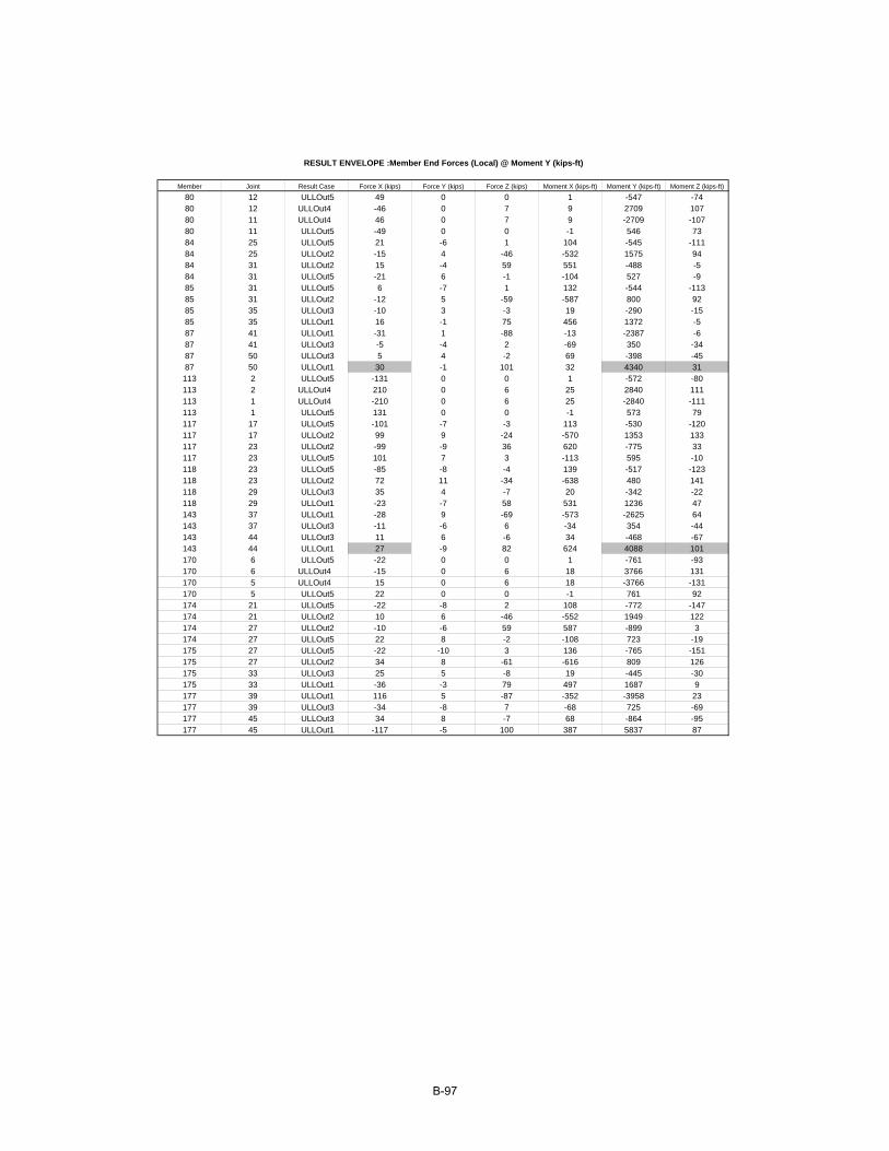
Member Joint Result Case Force X (kips) Force Y (kips) Force Z (kips) Moment X (kips-ft) Moment Y (kips-ft) Moment Z (kips-ft)
80 12 ULLOut5 49 0 0 1 -547 -7480 12 ULLOut4� -46 0 7 9 2709 10780 11 ULLOut4� 46 0 7 9 -2709 -10780 11 ULLOut5 -49 0 0 -1 546 7384 25 ULLOut5 21 -6 1 104 -545 -11184 25 ULLOut2 -15 4 -46 -532 1575 9484 31 ULLOut2 15 -4 59 551 -488 -584 31 ULLOut5 -21 6 -1 -104 527 -985 31 ULLOut5 6 -7 1 132 -544 -11385 31 ULLOut2 -12 5 -59 -587 800 9285 35 ULLOut3 -10 3 -3 19 -290 -1585 35 ULLOut1 16 -1 75 456 1372 -587 41 ULLOut1 -31 1 -88 -13 -2387 -687 41 ULLOut3 -5 -4 2 -69 350 -3487 50 ULLOut3 5 4 -2 69 -398 -4587 50 ULLOut1 30 -1 101 32 4340 31113 2 ULLOut5 -131 0 0 1 -572 -80113 2 ULLOut4� 210 0 6 25 2840 111113 1 ULLOut4� -210 0 6 25 -2840 -111113 1 ULLOut5 131 0 0 -1 573 79117 17 ULLOut5 -101 -7 -3 113 -530 -120117 17 ULLOut2 99 9 -24 -570 1353 133117 23 ULLOut2 -99 -9 36 620 -775 33117 23 ULLOut5 101 7 3 -113 595 -10118 23 ULLOut5 -85 -8 -4 139 -517 -123118 23 ULLOut2 72 11 -34 -638 480 141118 29 ULLOut3 35 4 -7 20 -342 -22118 29 ULLOut1 -23 -7 58 531 1236 47143 37 ULLOut1 -28 9 -69 -573 -2625 64143 37 ULLOut3 -11 -6 6 -34 354 -44143 44 ULLOut3 11 6 -6 34 -468 -67143 44 ULLOut1 27 -9 82 624 4088 101170 6 ULLOut5 -22 0 0 1 -761 -93170 6 ULLOut4� -15 0 6 18 3766 131170 5 ULLOut4� 15 0 6 18 -3766 -131170 5 ULLOut5 22 0 0 -1 761 92174 21 ULLOut5 -22 -8 2 108 -772 -147174 21 ULLOut2 10 6 -46 -552 1949 122174 27 ULLOut2 -10 -6 59 587 -899 3174 27 ULLOut5 22 8 -2 -108 723 -19175 27 ULLOut5 -22 -10 3 136 -765 -151175 27 ULLOut2 34 8 -61 -616 809 126175 33 ULLOut3 25 5 -8 19 -445 -30175 33 ULLOut1 -36 -3 79 497 1687 9177 39 ULLOut1 116 5 -87 -352 -3958 23177 39 ULLOut3 -34 -8 7 -68 725 -69177 45 ULLOut3 34 8 -7 68 -864 -95177 45 ULLOut1 -117 -5 100 387 5837 87
RESULT ENVELOPE :Member End Forces (Local) @ Moment Y (kips-ft)
B-97

Member Joint Result Case Force X (kips) Force Y (kips) Force Z (kips) Moment X (kips-ft) Moment Y (kips-ft) Moment Z (kips-ft)
80 12 ULLMid5 47 0 0 0 -525 -7180 12 ULLMid2 -24 0 11 -10 2423 7580 11 ULLMid3 -23 0 -4 1 222 3780 11 ULLMid1 1 0 7 -9 -2202 -3884 25 ULLMid4 -31 7 -47 -437 1464 14884 25 ULLMid3 15 -3 4 6 110 -5184 31 ULLMid3 -15 3 -4 -6 -190 -284 31 ULLMid4 31 -7 60 419 -356 -585 31 ULLMid4 -22 9 -59 -451 584 14685 31 ULLMid3 9 -3 4 -6 213 -5185 35 ULLMid3 -9 3 -4 6 -289 -1585 35 ULLMid4 22 -9 73 434 778 3087 41 ULLMid1 -29 1 -84 132 -2330 187 41 ULLMid3 -5 -4 3 -55 340 -3287 50 ULLMid3 5 4 -3 55 -396 -4487 50 ULLMid1 29 -1 98 -150 4213 28113 2 ULLMid5 -126 0 0 0 -549 -76113 2 ULLMid2 151 0 14 5 2521 72113 1 ULLMid3 63 0 -8 3 201 35113 1 ULLMid1 -88 0 6 8 -2320 -37117 17 ULLMid1 50 6 -37 -355 818 81117 17 ULLMid3 -43 -3 6 6 99 -59117 23 ULLMid3 43 3 -6 -6 -224 -7117 23 ULLMid1 -50 -6 49 372 14 29118 23 ULLMid1 29 7 -48 -357 -143 87118 23 ULLMid3 -33 -4 6 -5 208 -60118 29 ULLMid3 33 4 -6 5 -329 -21118 29 ULLMid1 -29 -7 61 374 1194 47143 37 ULLMid1 -24 9 -73 -409 -2530 72143 37 ULLMid3 -10 -6 5 -20 349 -42143 44 ULLMid3 10 6 -5 20 -449 -65143 44 ULLMid1 23 -9 85 425 4058 101170 6 ULLMid5 -21 0 0 0 -731 -89170 6 ULLMid2 -25 0 13 -2 3369 88170 5 ULLMid3 11 0 -6 2 302 44170 5 ULLMid1 36 0 6 0 -3066 -45174 21 ULLMid4 33 11 -54 -451 1861 204174 21 ULLMid3 -21 -4 8 6 134 -72174 27 ULLMid3 21 4 -8 -6 -285 -11174 27 ULLMid4 -33 -11 67 451 -659 17175 27 ULLMid4 58 14 -69 -473 584 210175 27 ULLMid3 -24 -5 8 -5 276 -74175 33 ULLMid3 24 5 -8 5 -435 -29175 33 ULLMid4 -58 -14 82 473 931 69177 39 ULLMid4 141 22 -91 -346 -3528 154177 39 ULLMid3 -33 -8 7 -51 707 -65177 45 ULLMid3 33 8 -7 51 -841 -93177 45 ULLMid4 -142 -22 104 346 5482 279
RESULT ENVELOPE :Member End Forces (Local) @ Force Z (kips)
B-98

Member Joint Result Case Force X (kips) Force Y (kips) Force Z (kips) Moment X (kips-ft) Moment Y (kips-ft) Moment Z (kips-ft)
80 12 ULLMid2 -24 0 11 -10 2423 7580 12 ULLMid5 47 0 0 0 -525 -7180 11 ULLMid1 1 0 7 -9 -2202 -3880 11 ULLMid3 -23 0 -4 1 222 3784 25 ULLMid4 -31 7 -47 -437 1464 14884 25 ULLMid5 21 -6 1 99 -523 -10684 31 ULLMid5 -21 6 -1 -99 506 -884 31 ULLMid4 31 -7 60 419 -356 -585 31 ULLMid2 -13 5 -56 -457 798 9585 31 ULLMid5 6 -7 1 126 -521 -10885 35 ULLMid5 -6 7 -1 -126 507 -3485 35 ULLMid2 13 -5 69 439 489 1687 41 ULLMid2 -5 6 -80 -186 -1295 3887 41 ULLMid5 -29 -8 -2 263 -695 -6987 50 ULLMid5 29 8 2 -263 732 -10687 50 ULLMid2 4 -6 93 169 3084 90113 2 ULLMid3 -63 0 8 -3 -349 -40113 2 ULLMid1 88 0 6 8 2320 37113 1 ULLMid5 126 0 0 0 550 76113 1 ULLMid2 -151 0 -1 11 -2668 -78117 17 ULLMid4 147 12 -34 -462 1326 196117 17 ULLMid5 -97 -6 -3 107 -508 -115117 23 ULLMid5 97 6 3 -107 571 -9117 23 ULLMid4 -147 -12 46 479 -557 38118 23 ULLMid2 77 11 -38 -494 561 144118 23 ULLMid5 -81 -8 -4 132 -496 -117118 29 ULLMid5 81 8 4 -132 575 -37118 29 ULLMid2 -77 -11 50 511 290 64143 37 ULLMid2 7 14 -59 -523 -1492 106143 37 ULLMid5 -41 -11 -8 94 -689 -76143 44 ULLMid5 41 11 8 -94 846 -136143 44 ULLMid2 -8 -14 72 540 2763 171170 6 ULLMid2 -25 0 13 -2 3369 88170 6 ULLMid5 -21 0 0 0 -731 -89170 5 ULLMid5 21 0 0 0 731 88170 5 ULLMid2 25 0 0 2 -3496 -89174 21 ULLMid4 33 11 -54 -451 1861 204174 21 ULLMid5 -21 -8 2 102 -741 -141174 27 ULLMid5 21 8 -2 -102 692 -18174 27 ULLMid4 -33 -11 67 451 -659 17175 27 ULLMid2 34 9 -61 -479 860 136175 27 ULLMid5 -21 -10 3 130 -735 -145175 33 ULLMid5 21 10 -3 -130 667 -53175 33 ULLMid2 -34 -9 74 479 496 41177 39 ULLMid2 108 14 -84 -397 -2821 89177 39 ULLMid5 -24 -14 4 211 -313 -104177 45 ULLMid5 24 14 -4 -211 230 -185177 45 ULLMid2 -109 -14 97 397 4641 186
RESULT ENVELOPE :Member End Forces (Local) @ Moment X (kips-ft)
B-99

Member Joint Result Case Force X (kips) Force Y (kips) Force Z (kips) Moment X (kips-ft) Moment Y (kips-ft) Moment Z (kips-ft)
80 12 ULLMid5 47 0 0 0 -525 -7180 12 ULLMid4 -47 0 7 -9 2727 10980 11 ULLMid4 47 0 7 -9 -2727 -10980 11 ULLMid5 -47 0 0 0 525 7184 25 ULLMid5 21 -6 1 99 -523 -10684 25 ULLMid2 -16 4 -43 -431 1574 9784 31 ULLMid2 16 -4 56 413 -546 -784 31 ULLMid5 -21 6 -1 -99 506 -885 31 ULLMid5 6 -7 1 126 -521 -10885 31 ULLMid2 -13 5 -56 -457 798 9585 35 ULLMid3 -9 3 -4 6 -289 -1585 35 ULLMid1 16 -2 72 308 1285 -487 41 ULLMid1 -29 1 -84 132 -2330 187 41 ULLMid3 -5 -4 3 -55 340 -3287 50 ULLMid3 5 4 -3 55 -396 -4487 50 ULLMid1 29 -1 98 -150 4213 28113 2 ULLMid5 -126 0 0 0 -549 -76113 2 ULLMid4 213 0 6 8 2869 113113 1 ULLMid4 -213 0 6 8 -2869 -113113 1 ULLMid5 126 0 0 0 550 76117 17 ULLMid5 -97 -6 -3 107 -508 -115117 17 ULLMid2 104 9 -27 -456 1425 137117 23 ULLMid2 -104 -9 39 473 -781 31117 23 ULLMid5 97 6 3 -107 571 -9118 23 ULLMid5 -81 -8 -4 132 -496 -117118 23 ULLMid2 77 11 -38 -494 561 144118 29 ULLMid3 33 4 -6 5 -329 -21118 29 ULLMid1 -29 -7 61 374 1194 47143 37 ULLMid1 -24 9 -73 -409 -2530 72143 37 ULLMid3 -10 -6 5 -20 349 -42143 44 ULLMid3 10 6 -5 20 -449 -65143 44 ULLMid1 23 -9 85 425 4058 101170 6 ULLMid5 -21 0 0 0 -731 -89170 6 ULLMid4 -15 0 6 0 3798 133170 5 ULLMid4 15 0 6 0 -3798 -133170 5 ULLMid5 21 0 0 0 731 88174 21 ULLMid5 -21 -8 2 102 -741 -141174 21 ULLMid2 11 7 -46 -445 1996 132174 27 ULLMid2 -11 -7 59 445 -943 7174 27 ULLMid5 21 8 -2 -102 692 -18175 27 ULLMid5 -21 -10 3 130 -735 -145175 27 ULLMid2 34 9 -61 -479 860 136175 33 ULLMid3 24 5 -8 5 -435 -29175 33 ULLMid1 -37 -4 79 344 1598 17177 39 ULLMid1 117 7 -87 -136 -3840 50177 39 ULLMid3 -33 -8 7 -51 707 -65177 45 ULLMid3 33 8 -7 51 -841 -93177 45 ULLMid1 -118 -7 100 136 5711 94
RESULT ENVELOPE :Member End Forces (Local) @ Moment Y (kips-ft)
B-100
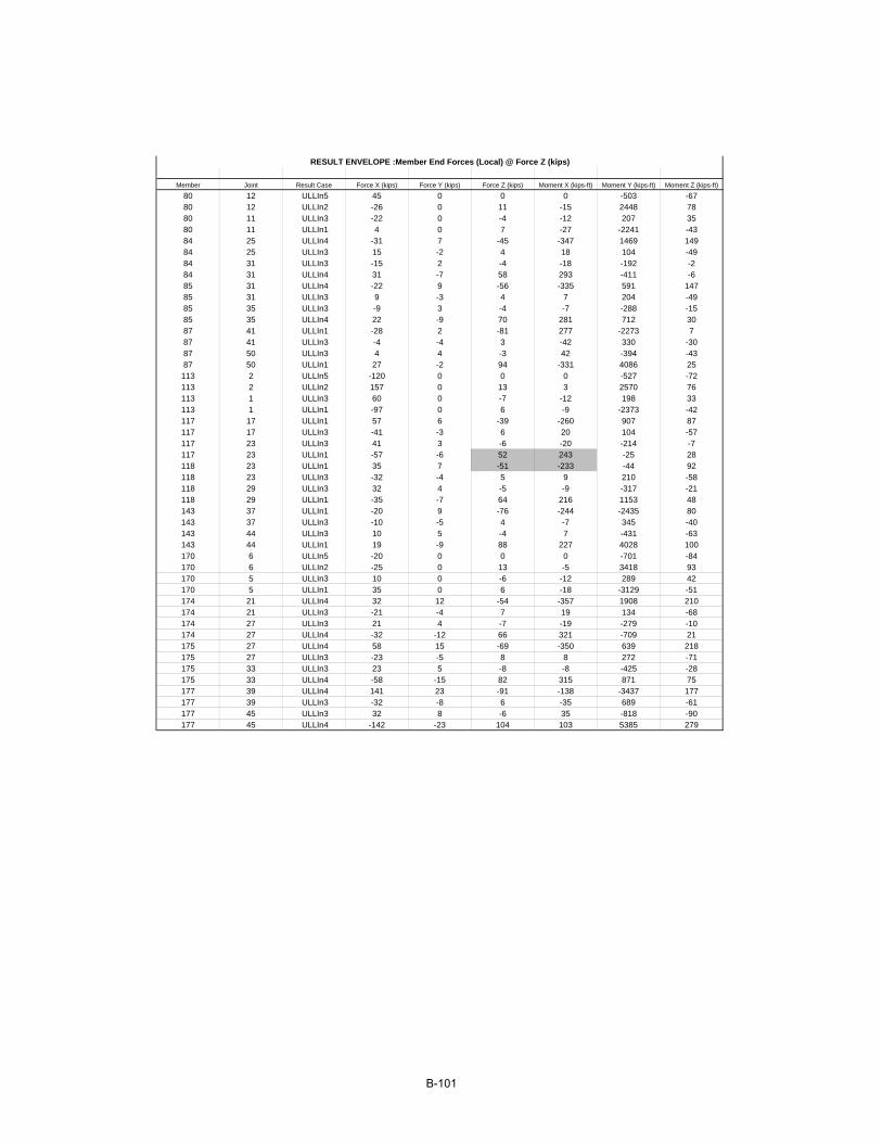
Member Joint Result Case Force X (kips) Force Y (kips) Force Z (kips) Moment X (kips-ft) Moment Y (kips-ft) Moment Z (kips-ft)
80 12 ULLIn5 45 0 0 0 -503 -6780 12 ULLIn2 -26 0 11 -15 2448 7880 11 ULLIn3 -22 0 -4 -12 207 3580 11 ULLIn1 4 0 7 -27 -2241 -4384 25 ULLIn4 -31 7 -45 -347 1469 14984 25 ULLIn3 15 -2 4 18 104 -4984 31 ULLIn3 -15 2 -4 -18 -192 -284 31 ULLIn4 31 -7 58 293 -411 -685 31 ULLIn4 -22 9 -56 -335 591 14785 31 ULLIn3 9 -3 4 7 204 -4985 35 ULLIn3 -9 3 -4 -7 -288 -1585 35 ULLIn4 22 -9 70 281 712 3087 41 ULLIn1 -28 2 -81 277 -2273 787 41 ULLIn3 -4 -4 3 -42 330 -3087 50 ULLIn3 4 4 -3 42 -394 -4387 50 ULLIn1 27 -2 94 -331 4086 25113 2 ULLIn5 -120 0 0 0 -527 -72113 2 ULLIn2 157 0 13 3 2570 76113 1 ULLIn3 60 0 -7 -12 198 33113 1 ULLIn1 -97 0 6 -9 -2373 -42117 17 ULLIn1 57 6 -39 -260 907 87117 17 ULLIn3 -41 -3 6 20 104 -57117 23 ULLIn3 41 3 -6 -20 -214 -7117 23 ULLIn1 -57 -6 52 243 -25 28118 23 ULLIn1 35 7 -51 -233 -44 92118 23 ULLIn3 -32 -4 5 9 210 -58118 29 ULLIn3 32 4 -5 -9 -317 -21118 29 ULLIn1 -35 -7 64 216 1153 48143 37 ULLIn1 -20 9 -76 -244 -2435 80143 37 ULLIn3 -10 -5 4 -7 345 -40143 44 ULLIn3 10 5 -4 7 -431 -63143 44 ULLIn1 19 -9 88 227 4028 100170 6 ULLIn5 -20 0 0 0 -701 -84170 6 ULLIn2 -25 0 13 -5 3418 93170 5 ULLIn3 10 0 -6 -12 289 42170 5 ULLIn1 35 0 6 -18 -3129 -51174 21 ULLIn4 32 12 -54 -357 1908 210174 21 ULLIn3 -21 -4 7 19 134 -68174 27 ULLIn3 21 4 -7 -19 -279 -10174 27 ULLIn4 -32 -12 66 321 -709 21175 27 ULLIn4 58 15 -69 -350 639 218175 27 ULLIn3 -23 -5 8 8 272 -71175 33 ULLIn3 23 5 -8 -8 -425 -28175 33 ULLIn4 -58 -15 82 315 871 75177 39 ULLIn4 141 23 -91 -138 -3437 177177 39 ULLIn3 -32 -8 6 -35 689 -61177 45 ULLIn3 32 8 -6 35 -818 -90177 45 ULLIn4 -142 -23 104 103 5385 279
RESULT ENVELOPE :Member End Forces (Local) @ Force Z (kips)
B-101

Member Joint Result Case Force X (kips) Force Y (kips) Force Z (kips) Moment X (kips-ft) Moment Y (kips-ft) Moment Z (kips-ft)
80 12 ULLIn1 -4 0 7 -27 2241 4380 12 ULLIn3 22 0 4 12 -296 -3280 11 ULLIn2 26 0 2 -39 -2537 -7580 11 ULLIn5 -45 0 0 0 503 6884 25 ULLIn4 -31 7 -45 -347 1469 14984 25 ULLIn5 20 -5 1 94 -500 -10284 31 ULLIn5 -20 5 -1 -94 485 -784 31 ULLIn4 31 -7 58 293 -411 -685 31 ULLIn4 -22 9 -56 -335 591 14785 31 ULLIn5 6 -7 1 120 -498 -10485 35 ULLIn5 -6 7 -1 -120 486 -3385 35 ULLIn4 22 -9 70 281 712 3087 41 ULLIn3 -4 -4 3 -42 330 -3087 41 ULLIn1 -28 2 -81 277 -2273 787 50 ULLIn1 27 -2 94 -331 4086 2587 50 ULLIn3 4 4 -3 42 -394 -43113 2 ULLIn1 97 0 6 -9 2373 42113 2 ULLIn3 -60 0 7 12 -329 -39113 1 ULLIn2 -157 0 -1 -21 -2701 -81113 1 ULLIn5 120 0 0 0 527 73117 17 ULLIn4 150 12 -36 -362 1393 197117 17 ULLIn5 -93 -6 -3 102 -486 -110117 23 ULLIn5 93 6 3 -102 547 -8117 23 ULLIn4 -150 -12 49 345 -573 37118 23 ULLIn4 113 15 -47 -359 431 205118 23 ULLIn5 -78 -8 -4 125 -475 -112118 29 ULLIn5 78 8 4 -125 552 -35118 29 ULLIn4 -113 -15 60 342 601 84143 37 ULLIn2 10 14 -64 -328 -1422 112143 37 ULLIn5 -40 -10 -8 77 -668 -73143 44 ULLIn5 40 10 8 -77 821 -128143 44 ULLIn2 -11 -14 76 311 2776 166170 6 ULLIn1 -35 0 6 -18 3129 51170 6 ULLIn3 -10 0 6 12 -411 -43170 5 ULLIn2 25 0 0 -30 -3540 -93170 5 ULLIn5 20 0 0 0 701 85174 21 ULLIn4 32 12 -54 -357 1908 210174 21 ULLIn5 -20 -8 2 97 -711 -134174 27 ULLIn5 20 8 -2 -97 662 -17174 27 ULLIn4 -32 -12 66 321 -709 21175 27 ULLIn4 58 15 -69 -350 639 218175 27 ULLIn5 -20 -9 3 123 -705 -138175 33 ULLIn5 20 9 -3 -123 637 -50175 33 ULLIn4 -58 -15 82 315 871 75177 39 ULLIn2 109 15 -84 -173 -2748 116177 39 ULLIn5 -23 -14 4 218 -285 -99177 45 ULLIn5 23 14 -4 -218 201 -178177 45 ULLIn2 -110 -15 97 138 4566 189
RESULT ENVELOPE :Member End Forces (Local) @ Moment X (kips-ft)
B-102

Member Joint Result Case Force X (kips) Force Y (kips) Force Z (kips) Moment X (kips-ft) Moment Y (kips-ft) Moment Z (kips-ft)
80 12 ULLIn5 45 0 0 0 -503 -6780 12 ULLIn4 -48 0 7 -27 2744 11080 11 ULLIn4 48 0 7 -27 -2744 -11080 11 ULLIn5 -45 0 0 0 503 6884 25 ULLIn5 20 -5 1 94 -500 -10284 25 ULLIn2 -17 4 -40 -329 1573 10084 31 ULLIn2 17 -4 54 275 -603 -884 31 ULLIn5 -20 5 -1 -94 485 -785 31 ULLIn5 6 -7 1 120 -498 -10485 31 ULLIn2 -13 5 -52 -327 795 9885 35 ULLIn3 -9 3 -4 -7 -288 -1585 35 ULLIn1 16 -2 69 160 1198 -387 41 ULLIn1 -28 2 -81 277 -2273 787 41 ULLIn3 -4 -4 3 -42 330 -3087 50 ULLIn3 4 4 -3 42 -394 -4387 50 ULLIn1 27 -2 94 -331 4086 25113 2 ULLIn5 -120 0 0 0 -527 -72113 2 ULLIn4 217 0 6 -9 2899 115113 1 ULLIn4 -217 0 6 -9 -2899 -115113 1 ULLIn5 120 0 0 0 527 73117 17 ULLIn5 -93 -6 -3 102 -486 -110117 17 ULLIn2 109 9 -31 -342 1497 140117 23 ULLIn2 -109 -9 43 325 -787 30117 23 ULLIn5 93 6 3 -102 547 -8118 23 ULLIn5 -78 -8 -4 125 -475 -112118 23 ULLIn2 81 11 -42 -350 642 147118 29 ULLIn3 32 4 -5 -9 -317 -21118 29 ULLIn1 -35 -7 64 216 1153 48143 37 ULLIn1 -20 9 -76 -244 -2435 80143 37 ULLIn3 -10 -5 4 -7 345 -40143 44 ULLIn3 10 5 -4 7 -431 -63143 44 ULLIn1 19 -9 88 227 4028 100170 6 ULLIn5 -20 0 0 0 -701 -84170 6 ULLIn4 -14 0 6 -18 3829 135170 5 ULLIn4 14 0 6 -18 -3829 -135170 5 ULLIn5 20 0 0 0 701 85174 21 ULLIn5 -20 -8 2 97 -711 -134174 21 ULLIn2 12 8 -46 -337 2042 142174 27 ULLIn2 -12 -8 59 302 -988 10174 27 ULLIn5 20 8 -2 -97 662 -17175 27 ULLIn5 -20 -9 3 123 -705 -138175 27 ULLIn2 35 10 -61 -342 911 147175 33 ULLIn3 23 5 -8 -8 -425 -28175 33 ULLIn1 -38 -5 79 191 1509 24177 39 ULLIn1 118 9 -87 81 -3722 78177 39 ULLIn3 -32 -8 6 -35 689 -61177 45 ULLIn3 32 8 -6 35 -818 -90177 45 ULLIn1 -119 -9 99 -116 5586 101
RESULT ENVELOPE :Member End Forces (Local) @ Moment Y (kips-ft)
B-103
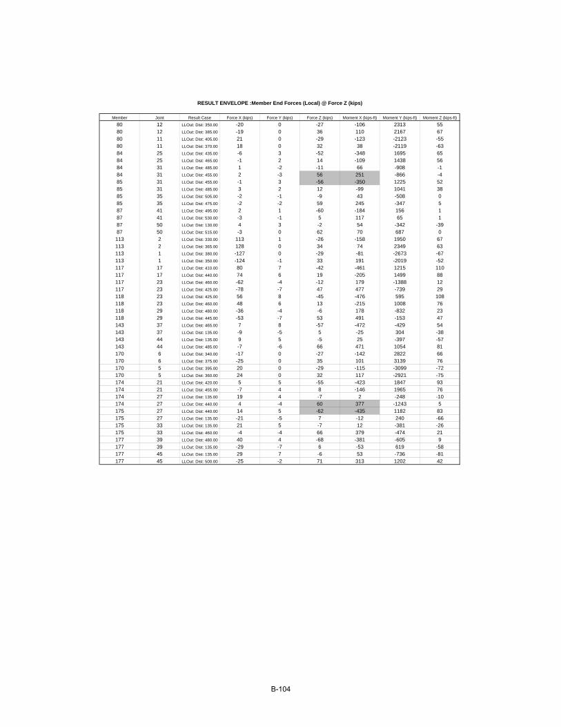
Member Joint Result Case Force X (kips) Force Y (kips) Force Z (kips) Moment X (kips-ft) Moment Y (kips-ft) Moment Z (kips-ft)
80 12 LLOut: Dist: 350.00 -20 0 -27 -106 2313 5580 12 LLOut: Dist: 385.00 -19 0 36 110 2167 6780 11 LLOut: Dist: 405.00 21 0 -29 -123 -2123 -5580 11 LLOut: Dist: 370.00 18 0 32 38 -2119 -6384 25 LLOut: Dist: 435.00 -6 3 -52 -348 1695 6584 25 LLOut: Dist: 465.00 -1 2 14 -109 1438 5684 31 LLOut: Dist: 485.00 1 -2 -11 66 -908 -184 31 LLOut: Dist: 455.00 2 -3 56 251 -866 -485 31 LLOut: Dist: 455.00 -1 3 -56 -350 1225 5285 31 LLOut: Dist: 485.00 3 2 12 -99 1041 3885 35 LLOut: Dist: 505.00 -2 -1 -9 43 -508 085 35 LLOut: Dist: 475.00 -2 -2 59 245 -347 587 41 LLOut: Dist: 495.00 2 1 -60 -184 156 187 41 LLOut: Dist: 530.00 -3 -1 5 117 65 187 50 LLOut: Dist: 130.00 4 3 -2 54 -342 -3987 50 LLOut: Dist: 515.00 -3 0 62 70 687 0113 2 LLOut: Dist: 330.00 113 1 -26 -158 1950 67113 2 LLOut: Dist: 365.00 128 0 34 74 2349 63113 1 LLOut: Dist: 380.00 -127 0 -29 -81 -2673 -67113 1 LLOut: Dist: 350.00 -124 -1 33 191 -2019 -52117 17 LLOut: Dist: 410.00 80 7 -42 -461 1215 110117 17 LLOut: Dist: 440.00 74 6 19 -205 1499 88117 23 LLOut: Dist: 460.00 -62 -4 -12 179 -1388 12117 23 LLOut: Dist: 425.00 -78 -7 47 477 -739 29118 23 LLOut: Dist: 425.00 56 8 -45 -476 595 108118 23 LLOut: Dist: 460.00 48 6 13 -215 1008 76118 29 LLOut: Dist: 480.00 -36 -4 -6 178 -832 23118 29 LLOut: Dist: 445.00 -53 -7 53 491 -153 47143 37 LLOut: Dist: 465.00 7 8 -57 -472 -429 54143 37 LLOut: Dist: 135.00 -9 -5 5 -25 304 -38143 44 LLOut: Dist: 135.00 9 5 -5 25 -397 -57143 44 LLOut: Dist: 485.00 -7 -6 66 471 1054 81170 6 LLOut: Dist: 340.00 -17 0 -27 -142 2822 66170 6 LLOut: Dist: 375.00 -25 0 35 101 3139 76170 5 LLOut: Dist: 395.00 20 0 -29 -115 -3099 -72170 5 LLOut: Dist: 360.00 24 0 32 117 -2921 -75174 21 LLOut: Dist: 420.00 5 5 -55 -423 1847 93174 21 LLOut: Dist: 455.00 -7 4 8 -146 1965 76174 27 LLOut: Dist: 135.00 19 4 -7 2 -248 -10174 27 LLOut: Dist: 440.00 4 -4 60 377 -1243 5175 27 LLOut: Dist: 440.00 14 5 -62 -435 1182 83175 27 LLOut: Dist: 135.00 -21 -5 7 -12 240 -66175 33 LLOut: Dist: 135.00 21 5 -7 12 -381 -26175 33 LLOut: Dist: 460.00 -4 -4 66 379 -474 21177 39 LLOut: Dist: 480.00 40 4 -68 -381 -605 9177 39 LLOut: Dist: 135.00 -29 -7 6 -53 619 -58177 45 LLOut: Dist: 135.00 29 7 -6 53 -736 -81177 45 LLOut: Dist: 500.00 -25 -2 71 313 1202 42
RESULT ENVELOPE :Member End Forces (Local) @ Force Z (kips)
B-104
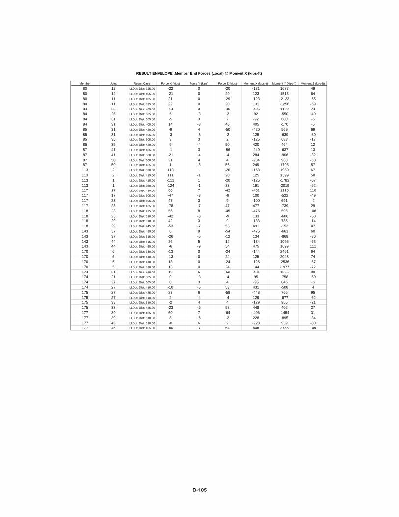
Member Joint Result Case Force X (kips) Force Y (kips) Force Z (kips) Moment X (kips-ft) Moment Y (kips-ft) Moment Z (kips-ft)
80 12 LLOut: Dist: 325.00 -22 0 -20 -131 1677 4980 12 LLOut: Dist: 405.00 -21 0 29 123 1513 6480 11 LLOut: Dist: 405.00 21 0 -29 -123 -2123 -5580 11 LLOut: Dist: 325.00 22 0 20 131 -1256 -5984 25 LLOut: Dist: 405.00 -14 3 -46 -405 1122 7484 25 LLOut: Dist: 605.00 5 -3 -2 92 -550 -4984 31 LLOut: Dist: 605.00 -5 3 2 -92 600 -684 31 LLOut: Dist: 405.00 14 -3 46 405 -170 -585 31 LLOut: Dist: 420.00 -9 4 -50 -420 569 6985 31 LLOut: Dist: 605.00 -3 -3 -2 125 -639 -5085 35 LLOut: Dist: 605.00 3 3 2 -125 688 -1785 35 LLOut: Dist: 420.00 9 -4 50 420 464 1287 41 LLOut: Dist: 455.00 -1 3 -56 -249 -637 1387 41 LLOut: Dist: 600.00 -21 -4 -4 284 -906 -3287 50 LLOut: Dist: 600.00 21 4 4 -284 983 -5387 50 LLOut: Dist: 455.00 1 -3 56 249 1795 57113 2 LLOut: Dist: 330.00 113 1 -26 -158 1950 67113 2 LLOut: Dist: 415.00 111 -1 20 125 1399 50113 1 LLOut: Dist: 415.00 -111 1 -20 -125 -1782 -67113 1 LLOut: Dist: 350.00 -124 -1 33 191 -2019 -52117 17 LLOut: Dist: 410.00 80 7 -42 -461 1215 110117 17 LLOut: Dist: 605.00 -47 -3 -9 100 -522 -49117 23 LLOut: Dist: 605.00 47 3 9 -100 691 -2117 23 LLOut: Dist: 425.00 -78 -7 47 477 -739 29118 23 LLOut: Dist: 425.00 56 8 -45 -476 595 108118 23 LLOut: Dist: 610.00 -42 -3 -9 133 -606 -50118 29 LLOut: Dist: 610.00 42 3 9 -133 785 -14118 29 LLOut: Dist: 445.00 -53 -7 53 491 -153 47143 37 LLOut: Dist: 455.00 6 9 -54 -475 -661 60143 37 LLOut: Dist: 615.00 -26 -5 -12 134 -868 -30143 44 LLOut: Dist: 615.00 26 5 12 -134 1095 -63143 44 LLOut: Dist: 455.00 -6 -9 54 475 1699 111170 6 LLOut: Dist: 330.00 -13 0 -24 -144 2461 64170 6 LLOut: Dist: 410.00 -13 0 24 125 2048 74170 5 LLOut: Dist: 410.00 13 0 -24 -125 -2536 -67170 5 LLOut: Dist: 330.00 13 0 24 144 -1977 -72174 21 LLOut: Dist: 410.00 10 5 -53 -431 1565 99174 21 LLOut: Dist: 605.00 0 -3 -4 95 -758 -60174 27 LLOut: Dist: 605.00 0 3 4 -95 846 -6174 27 LLOut: Dist: 410.00 -10 -5 53 431 -508 4175 27 LLOut: Dist: 425.00 23 6 -58 -448 766 95175 27 LLOut: Dist: 610.00 2 -4 -4 129 -877 -62175 33 LLOut: Dist: 610.00 -2 4 4 -129 955 -21175 33 LLOut: Dist: 425.00 -23 -6 58 448 402 27177 39 LLOut: Dist: 455.00 60 7 -64 -406 -1454 31177 39 LLOut: Dist: 610.00 8 -6 -2 228 -895 -34177 45 LLOut: Dist: 610.00 -8 6 2 -228 939 -80177 45 LLOut: Dist: 455.00 -60 -7 64 406 2735 109
RESULT ENVELOPE :Member End Forces (Local) @ Moment X (kips-ft)
B-105
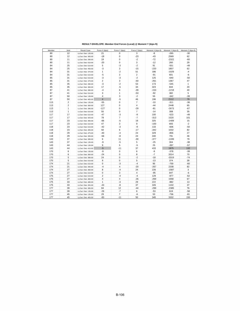
Member Joint Result Case Force X (kips) Force Y (kips) Force Z (kips) Moment X (kips-ft) Moment Y (kips-ft) Moment Z (kips-ft)
80 12 LLOut: Dist: 135.00 21 0 3 -8 -265 -3080 12 LLOut: Dist: 365.00 -18 0 -23 -43 2569 6280 11 LLOut: Dist: 390.00 19 0 -2 -72 -2322 -6080 11 LLOut: Dist: 610.00 -20 0 3 -12 260 2984 25 LLOut: Dist: 610.00 5 -3 -2 91 -551 -4984 25 LLOut: Dist: 450.00 -3 3 -15 -220 1807 6284 31 LLOut: Dist: 470.00 1 -2 51 186 -1029 -484 31 LLOut: Dist: 610.00 -5 3 2 -91 601 -685 31 LLOut: Dist: 610.00 -3 -3 -2 125 -640 -5085 31 LLOut: Dist: 470.00 2 3 -50 -261 1367 4785 35 LLOut: Dist: 490.00 -3 -2 53 173 -545 185 35 LLOut: Dist: 360.00 17 -5 34 323 844 2087 41 LLOut: Dist: 380.00 -4 6 -39 -153 -1218 4087 41 LLOut: Dist: 510.00 3 1 -53 -92 382 587 50 LLOut: Dist: 135.00 4 3 -2 55 -342 -3987 50 LLOut: Dist: 405.00 4 -5 46 196 2112 79113 2 LLOut: Dist: 135.00 -55 0 7 -10 -311 -36113 2 LLOut: Dist: 360.00 127 0 4 -44 2448 65113 1 LLOut: Dist: 380.00 -127 0 -29 -81 -2673 -67113 1 LLOut: Dist: 610.00 55 0 7 -14 308 35117 17 LLOut: Dist: 610.00 -47 -3 -9 100 -523 -49117 17 LLOut: Dist: 425.00 78 7 -7 -313 1520 101117 23 LLOut: Dist: 455.00 -66 -5 19 325 -1409 15117 23 LLOut: Dist: 610.00 47 3 9 -100 693 -2118 23 LLOut: Dist: 610.00 -42 -3 -9 133 -606 -50118 23 LLOut: Dist: 455.00 50 6 -17 -342 1032 82118 29 LLOut: Dist: 475.00 -40 -4 24 329 -856 27118 29 LLOut: Dist: 355.00 -56 -8 24 340 791 46143 37 LLOut: Dist: 385.00 6 11 -30 -377 -1339 79143 37 LLOut: Dist: 135.00 -9 -5 5 -25 304 -38143 44 LLOut: Dist: 135.00 9 5 -5 25 -397 -57143 44 LLOut: Dist: 410.00 -5 -11 37 433 1975 132170 6 LLOut: Dist: 135.00 -9 0 6 -9 -378 -39170 6 LLOut: Dist: 360.00 -24 0 8 -7 3314 70170 5 LLOut: Dist: 380.00 24 0 -2 -18 -3319 -74170 5 LLOut: Dist: 610.00 9 0 5 -13 374 39174 21 LLOut: Dist: 610.00 0 -3 -4 95 -759 -60174 21 LLOut: Dist: 440.00 -4 4 -20 -267 2208 82174 27 LLOut: Dist: 460.00 8 -4 24 226 -1587 3174 27 LLOut: Dist: 610.00 0 3 4 -95 847 -6175 27 LLOut: Dist: 610.00 2 -4 -4 129 -877 -62175 27 LLOut: Dist: 460.00 4 4 -26 -269 1558 67175 33 LLOut: Dist: 480.00 1 -3 29 222 -882 13175 33 LLOut: Dist: 355.00 -43 -8 37 326 1102 37177 39 LLOut: Dist: 385.00 84 12 -44 -299 -2385 76177 39 LLOut: Dist: 135.00 -29 -7 6 -53 619 -58177 45 LLOut: Dist: 135.00 29 7 -6 53 -736 -81177 45 LLOut: Dist: 405.00 -83 -11 50 345 3332 150
RESULT ENVELOPE :Member End Forces (Local) @ Moment Y (kips-ft)
B-106
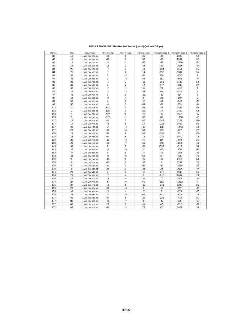
Member Joint Result Case Force X (kips) Force Y (kips) Force Z (kips) Moment X (kips-ft) Moment Y (kips-ft) Moment Z (kips-ft)
80 12 LLMid: Dist: 350.00 -20 0 -27 -36 2365 5680 12 LLMid: Dist: 380.00 -19 0 36 -28 2281 6780 11 LLMid: Dist: 400.00 21 -1 -30 -37 -2200 -5480 11 LLMid: Dist: 370.00 18 0 33 -29 -2156 -6484 25 LLMid: Dist: 430.00 -7 3 -51 -264 1651 6584 25 LLMid: Dist: 465.00 -1 2 14 -197 1304 5584 31 LLMid: Dist: 485.00 1 -2 -10 108 -830 184 31 LLMid: Dist: 450.00 2 -3 55 182 -853 -585 31 LLMid: Dist: 450.00 -1 3 -55 -258 1187 5285 31 LLMid: Dist: 485.00 3 2 12 -177 908 3785 35 LLMid: Dist: 505.00 -2 -1 -8 73 -435 285 35 LLMid: Dist: 470.00 -2 -2 58 168 -336 587 41 LLMid: Dist: 490.00 3 1 -59 -80 134 387 41 LLMid: Dist: 525.00 -2 -1 5 28 140 087 50 LLMid: Dist: 135.00 4 3 -2 46 -340 -3887 50 LLMid: Dist: 515.00 -4 0 63 -51 609 -8113 2 LLMid: Dist: 325.00 112 1 -26 -78 1882 66113 2 LLMid: Dist: 360.00 128 0 35 17 2409 64113 1 LLMid: Dist: 380.00 -127 0 -29 -30 -2631 -67113 1 LLMid: Dist: 345.00 -123 -1 32 80 -1930 -53117 17 LLMid: Dist: 405.00 81 7 -43 -346 1189 110117 17 LLMid: Dist: 440.00 73 6 17 -228 1457 85117 23 LLMid: Dist: 455.00 -64 -4 -12 198 -1443 14117 23 LLMid: Dist: 425.00 -79 -6 50 339 -827 27118 23 LLMid: Dist: 425.00 57 8 -48 -356 701 105118 23 LLMid: Dist: 455.00 50 6 13 -231 1079 78118 29 LLMid: Dist: 475.00 -39 -4 -6 186 -884 25118 29 LLMid: Dist: 445.00 -53 -7 55 340 -253 45143 37 LLMid: Dist: 465.00 8 8 -60 -333 -313 54143 37 LLMid: Dist: 130.00 -9 -5 4 -16 300 -36143 44 LLMid: Dist: 130.00 9 5 -4 16 -384 -55143 44 LLMid: Dist: 485.00 -8 -5 68 297 928 70170 6 LLMid: Dist: 340.00 -18 0 -27 -64 2912 68170 6 LLMid: Dist: 370.00 -25 0 36 1 3231 75170 5 LLMid: Dist: 390.00 20 0 -30 -37 -3195 -75170 5 LLMid: Dist: 360.00 24 0 33 24 -2996 -74174 21 LLMid: Dist: 420.00 3 5 -56 -312 1946 96174 21 LLMid: Dist: 450.00 -7 4 9 -215 2057 79174 27 LLMid: Dist: 130.00 18 4 -6 -7 -244 -9174 27 LLMid: Dist: 440.00 5 -5 61 251 -1332 7175 27 LLMid: Dist: 440.00 13 6 -62 -313 1292 85175 27 LLMid: Dist: 130.00 -21 -4 7 -3 237 -63175 33 LLMid: Dist: 130.00 21 4 -7 3 -373 -25175 33 LLMid: Dist: 460.00 -3 -5 66 243 -579 23177 39 LLMid: Dist: 480.00 37 5 -69 -221 -435 21177 39 LLMid: Dist: 130.00 -28 -7 6 -42 605 -55177 45 LLMid: Dist: 130.00 28 7 -6 42 -720 -79177 45 LLMid: Dist: 500.00 -22 -2 72 137 1027 33
RESULT ENVELOPE :Member End Forces (Local) @ Force Z (kips)
B-107

Member Joint Result Case Force X (kips) Force Y (kips) Force Z (kips) Moment X (kips-ft) Moment Y (kips-ft) Moment Z (kips-ft)
80 12 LLMid: Dist: 320.00 -23 -1 -19 -67 1603 4880 12 LLMid: Dist: 420.00 -23 1 23 52 1126 5980 11 LLMid: Dist: 395.00 20 -1 1 -68 -2250 -5680 11 LLMid: Dist: 320.00 23 1 19 67 -1209 -5984 25 LLMid: Dist: 395.00 -16 3 -43 -311 984 7684 25 LLMid: Dist: 610.00 4 -3 -3 81 -531 -4784 31 LLMid: Dist: 610.00 -4 3 3 -81 586 -584 31 LLMid: Dist: 395.00 16 -3 43 311 -101 -685 31 LLMid: Dist: 410.00 -11 4 -46 -320 447 7185 31 LLMid: Dist: 605.00 -3 -3 -3 113 -618 -4885 35 LLMid: Dist: 605.00 3 3 3 -113 672 -1785 35 LLMid: Dist: 410.00 11 -4 46 320 514 1387 41 LLMid: Dist: 440.00 -2 4 -52 -140 -801 2187 41 LLMid: Dist: 600.00 -20 -4 -4 263 -884 -3187 50 LLMid: Dist: 600.00 20 4 4 -263 967 -5187 50 LLMid: Dist: 440.00 2 -4 52 140 1886 60113 2 LLMid: Dist: 325.00 112 1 -26 -78 1882 66113 2 LLMid: Dist: 420.00 106 -1 19 59 1245 49113 1 LLMid: Dist: 420.00 -106 1 -19 -59 -1607 -65113 1 LLMid: Dist: 340.00 -121 -1 31 80 -1772 -52117 17 LLMid: Dist: 405.00 81 7 -43 -346 1189 110117 17 LLMid: Dist: 610.00 -46 -3 -8 88 -510 -47117 23 LLMid: Dist: 610.00 46 3 8 -88 668 -2117 23 LLMid: Dist: 405.00 -81 -7 43 346 -363 28118 23 LLMid: Dist: 415.00 58 8 -45 -358 479 110118 23 LLMid: Dist: 610.00 -40 -3 -9 120 -590 -48118 29 LLMid: Dist: 610.00 40 3 9 -120 759 -14118 29 LLMid: Dist: 415.00 -58 -8 45 358 384 50143 37 LLMid: Dist: 435.00 7 10 -49 -358 -923 71143 37 LLMid: Dist: 615.00 -26 -5 -11 115 -846 -28143 44 LLMid: Dist: 615.00 26 5 11 -115 1060 -59143 44 LLMid: Dist: 435.00 -7 -10 49 358 1866 117170 6 LLMid: Dist: 325.00 -11 0 -23 -73 2367 65170 6 LLMid: Dist: 420.00 -8 0 21 57 1685 68170 5 LLMid: Dist: 420.00 8 0 -21 -57 -2109 -64170 5 LLMid: Dist: 325.00 11 0 23 73 -1898 -70174 21 LLMid: Dist: 400.00 13 6 -50 -330 1383 106174 21 LLMid: Dist: 610.00 0 -3 -4 84 -737 -58174 27 LLMid: Dist: 610.00 0 3 4 -84 821 -6174 27 LLMid: Dist: 400.00 -13 -6 50 330 -376 7175 27 LLMid: Dist: 415.00 26 7 -56 -341 607 103175 27 LLMid: Dist: 605.00 2 -4 -4 116 -852 -60175 33 LLMid: Dist: 605.00 -2 4 4 -116 928 -20175 33 LLMid: Dist: 415.00 -26 -7 56 341 512 32177 39 LLMid: Dist: 440.00 68 9 -61 -273 -1713 54177 39 LLMid: Dist: 605.00 8 -6 -2 222 -864 -33177 45 LLMid: Dist: 605.00 -8 6 2 -222 904 -78177 45 LLMid: Dist: 440.00 -68 -9 61 273 2931 122
RESULT ENVELOPE :Member End Forces (Local) @ Moment X (kips-ft)
B-108
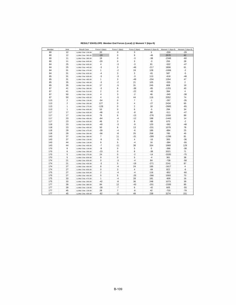
Member Joint Result Case Force X (kips) Force Y (kips) Force Z (kips) Moment X (kips-ft) Moment Y (kips-ft) Moment Z (kips-ft)
80 12 LLMid: Dist: 130.00 20 0 3 1 -259 -2980 12 LLMid: Dist: 365.00 -19 0 9 -46 2570 6280 11 LLMid: Dist: 385.00 19 0 -3 -38 -2348 -6080 11 LLMid: Dist: 605.00 -20 0 3 -3 255 2884 25 LLMid: Dist: 605.00 4 -3 -3 81 -532 -4784 25 LLMid: Dist: 445.00 -3 3 -46 -217 1806 6184 31 LLMid: Dist: 470.00 1 -2 19 128 -1006 -284 31 LLMid: Dist: 605.00 -4 3 3 -81 587 -585 31 LLMid: Dist: 605.00 -3 -3 -3 113 -618 -4885 31 LLMid: Dist: 465.00 1 3 -49 -204 1354 4785 35 LLMid: Dist: 490.00 -3 -2 21 105 -555 285 35 LLMid: Dist: 355.00 17 -5 31 245 808 1987 41 LLMid: Dist: 380.00 -3 6 -38 -85 -1201 4087 41 LLMid: Dist: 510.00 2 0 -22 -40 394 487 50 LLMid: Dist: 130.00 4 3 -2 46 -340 -3887 50 LLMid: Dist: 405.00 4 -5 44 116 2052 74113 2 LLMid: Dist: 130.00 -54 0 7 -1 -297 -35113 2 LLMid: Dist: 355.00 127 0 4 -27 2434 65113 1 LLMid: Dist: 375.00 -128 0 2 18 -2665 -65113 1 LLMid: Dist: 605.00 53 0 6 -5 294 34117 17 LLMid: Dist: 605.00 -46 -3 -8 88 -511 -47117 17 LLMid: Dist: 435.00 76 6 -13 -276 1559 89117 23 LLMid: Dist: 455.00 -64 -4 -12 198 -1443 14117 23 LLMid: Dist: 605.00 46 3 8 -88 670 -2118 23 LLMid: Dist: 605.00 -40 -3 -9 120 -592 -48118 23 LLMid: Dist: 455.00 50 6 13 -231 1079 78118 29 LLMid: Dist: 475.00 -39 -4 -6 186 -884 25118 29 LLMid: Dist: 350.00 -56 -8 25 258 785 45143 37 LLMid: Dist: 380.00 7 11 -31 -289 -1299 81143 37 LLMid: Dist: 130.00 -9 -5 4 -16 300 -36143 44 LLMid: Dist: 130.00 9 5 -4 16 -384 -55143 44 LLMid: Dist: 405.00 -7 -11 38 334 1969 129170 6 LLMid: Dist: 130.00 -9 0 5 0 -366 -38170 6 LLMid: Dist: 355.00 -23 0 8 -38 3321 71170 5 LLMid: Dist: 375.00 24 0 -2 -14 -3335 -75170 5 LLMid: Dist: 605.00 9 0 5 -4 361 38174 21 LLMid: Dist: 605.00 0 -3 -4 84 -738 -58174 21 LLMid: Dist: 435.00 -3 5 -19 -271 2241 87174 27 LLMid: Dist: 455.00 8 -4 24 195 -1617 4174 27 LLMid: Dist: 605.00 0 3 4 -84 822 -6175 27 LLMid: Dist: 605.00 2 -4 -4 116 -852 -60175 27 LLMid: Dist: 455.00 5 5 -25 -266 1593 73175 33 LLMid: Dist: 475.00 1 -4 28 181 -909 16175 33 LLMid: Dist: 350.00 -42 -8 36 248 1073 39177 39 LLMid: Dist: 380.00 84 12 -43 -201 -2335 85177 39 LLMid: Dist: 130.00 -28 -7 6 -42 605 -55177 45 LLMid: Dist: 130.00 28 7 -6 42 -720 -79177 45 LLMid: Dist: 400.00 -82 -11 49 238 3274 151
RESULT ENVELOPE :Member End Forces (Local) @ Moment Y (kips-ft)
B-109
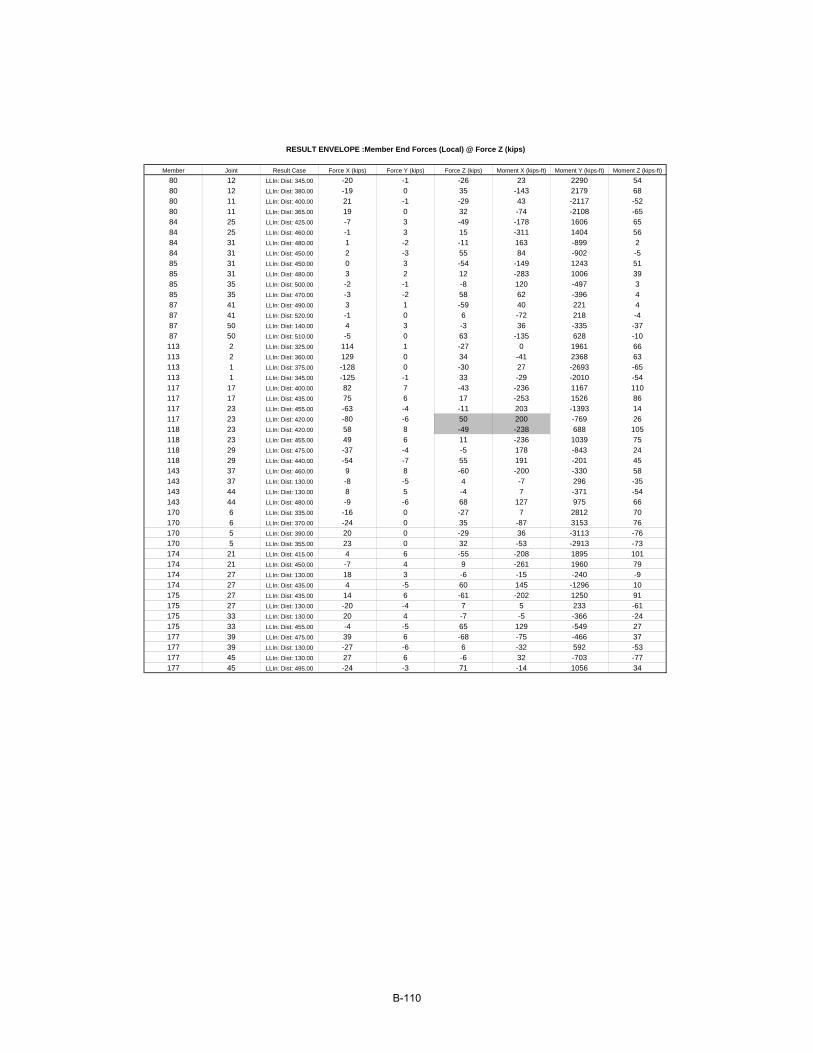
Member Joint Result Case Force X (kips) Force Y (kips) Force Z (kips) Moment X (kips-ft) Moment Y (kips-ft) Moment Z (kips-ft)
80 12 LLIn: Dist: 345.00 -20 -1 -26 23 2290 5480 12 LLIn: Dist: 380.00 -19 0 35 -143 2179 6880 11 LLIn: Dist: 400.00 21 -1 -29 43 -2117 -5280 11 LLIn: Dist: 365.00 19 0 32 -74 -2108 -6584 25 LLIn: Dist: 425.00 -7 3 -49 -178 1606 6584 25 LLIn: Dist: 460.00 -1 3 15 -311 1404 5684 31 LLIn: Dist: 480.00 1 -2 -11 163 -899 284 31 LLIn: Dist: 450.00 2 -3 55 84 -902 -585 31 LLIn: Dist: 450.00 0 3 -54 -149 1243 5185 31 LLIn: Dist: 480.00 3 2 12 -283 1006 3985 35 LLIn: Dist: 500.00 -2 -1 -8 120 -497 385 35 LLIn: Dist: 470.00 -3 -2 58 62 -396 487 41 LLIn: Dist: 490.00 3 1 -59 40 221 487 41 LLIn: Dist: 520.00 -1 0 6 -72 218 -487 50 LLIn: Dist: 140.00 4 3 -3 36 -335 -3787 50 LLIn: Dist: 510.00 -5 0 63 -135 628 -10113 2 LLIn: Dist: 325.00 114 1 -27 0 1961 66113 2 LLIn: Dist: 360.00 129 0 34 -41 2368 63113 1 LLIn: Dist: 375.00 -128 0 -30 27 -2693 -65113 1 LLIn: Dist: 345.00 -125 -1 33 -29 -2010 -54117 17 LLIn: Dist: 400.00 82 7 -43 -236 1167 110117 17 LLIn: Dist: 435.00 75 6 17 -253 1526 86117 23 LLIn: Dist: 455.00 -63 -4 -11 203 -1393 14117 23 LLIn: Dist: 420.00 -80 -6 50 200 -769 26118 23 LLIn: Dist: 420.00 58 8 -49 -238 688 105118 23 LLIn: Dist: 455.00 49 6 11 -236 1039 75118 29 LLIn: Dist: 475.00 -37 -4 -5 178 -843 24118 29 LLIn: Dist: 440.00 -54 -7 55 191 -201 45143 37 LLIn: Dist: 460.00 9 8 -60 -200 -330 58143 37 LLIn: Dist: 130.00 -8 -5 4 -7 296 -35143 44 LLIn: Dist: 130.00 8 5 -4 7 -371 -54143 44 LLIn: Dist: 480.00 -9 -6 68 127 975 66170 6 LLIn: Dist: 335.00 -16 0 -27 7 2812 70170 6 LLIn: Dist: 370.00 -24 0 35 -87 3153 76170 5 LLIn: Dist: 390.00 20 0 -29 36 -3113 -76170 5 LLIn: Dist: 355.00 23 0 32 -53 -2913 -73174 21 LLIn: Dist: 415.00 4 6 -55 -208 1895 101174 21 LLIn: Dist: 450.00 -7 4 9 -261 1960 79174 27 LLIn: Dist: 130.00 18 3 -6 -15 -240 -9174 27 LLIn: Dist: 435.00 4 -5 60 145 -1296 10175 27 LLIn: Dist: 435.00 14 6 -61 -202 1250 91175 27 LLIn: Dist: 130.00 -20 -4 7 5 233 -61175 33 LLIn: Dist: 130.00 20 4 -7 -5 -366 -24175 33 LLIn: Dist: 455.00 -4 -5 65 129 -549 27177 39 LLIn: Dist: 475.00 39 6 -68 -75 -466 37177 39 LLIn: Dist: 130.00 -27 -6 6 -32 592 -53177 45 LLIn: Dist: 130.00 27 6 -6 32 -703 -77177 45 LLIn: Dist: 495.00 -24 -3 71 -14 1056 34
RESULT ENVELOPE :Member End Forces (Local) @ Force Z (kips)
B-110
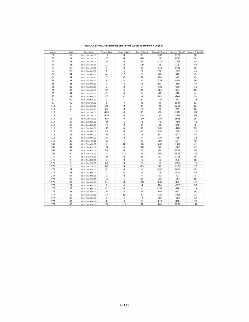
Member Joint Result Case Force X (kips) Force Y (kips) Force Z (kips) Moment X (kips-ft) Moment Y (kips-ft) Moment Z (kips-ft)
80 12 LLIn: Dist: 380.00 -19 0 35 -143 2179 6880 12 LLIn: Dist: 345.00 -20 -1 -26 23 2290 5480 11 LLIn: Dist: 380.00 19 0 29 -119 -2298 -6180 11 LLIn: Dist: 400.00 21 -1 -29 43 -2117 -5284 25 LLIn: Dist: 460.00 -1 3 15 -311 1404 5684 25 LLIn: Dist: 605.00 4 -2 -3 70 -512 -4584 31 LLIn: Dist: 605.00 -4 2 3 -70 572 -584 31 LLIn: Dist: 385.00 17 -3 39 220 -45 -685 31 LLIn: Dist: 480.00 3 2 12 -283 1006 3985 31 LLIn: Dist: 605.00 -3 -3 -3 101 -596 -4785 35 LLIn: Dist: 605.00 3 3 3 -101 655 -1685 35 LLIn: Dist: 400.00 12 -4 43 224 554 1387 41 LLIn: Dist: 520.00 -1 0 6 -72 218 -487 41 LLIn: Dist: 600.00 -20 -4 -4 243 -860 -3187 50 LLIn: Dist: 525.00 -1 1 60 -247 372 -2387 50 LLIn: Dist: 425.00 3 -4 48 39 1924 61113 2 LLIn: Dist: 360.00 129 0 34 -41 2368 63113 2 LLIn: Dist: 235.00 25 0 -5 21 201 16113 1 LLIn: Dist: 360.00 -129 0 30 -50 -2522 -58113 1 LLIn: Dist: 385.00 -126 0 -28 30 -2466 -68117 17 LLIn: Dist: 420.00 80 6 -10 -257 1566 98117 17 LLIn: Dist: 605.00 -44 -2 -8 76 -498 -45117 23 LLIn: Dist: 605.00 44 2 8 -76 646 -1117 23 LLIn: Dist: 385.00 -82 -7 39 240 -105 25118 23 LLIn: Dist: 400.00 59 8 -42 -250 290 114118 23 LLIn: Dist: 605.00 -39 -3 -8 107 -577 -47118 29 LLIn: Dist: 605.00 39 3 8 -107 735 -13118 29 LLIn: Dist: 400.00 -59 -8 42 250 524 49143 37 LLIn: Dist: 420.00 7 10 -46 -248 -1038 77143 37 LLIn: Dist: 620.00 -24 -4 -10 97 -807 -27143 44 LLIn: Dist: 620.00 24 4 10 -97 1006 -55143 44 LLIn: Dist: 420.00 -7 -10 46 248 1928 118170 6 LLIn: Dist: 370.00 -24 0 35 -87 3153 76170 6 LLIn: Dist: 235.00 3 0 -3 19 225 18170 5 LLIn: Dist: 370.00 24 0 29 -89 -3293 -76170 5 LLIn: Dist: 390.00 20 0 -29 36 -3113 -76174 21 LLIn: Dist: 450.00 -7 4 9 -261 1960 79174 21 LLIn: Dist: 605.00 0 -3 -4 73 -716 -56174 27 LLIn: Dist: 605.00 0 3 4 -73 797 -6174 27 LLIn: Dist: 390.00 -16 -6 48 232 -257 10175 27 LLIn: Dist: 400.00 31 8 -53 -240 364 113175 27 LLIn: Dist: 605.00 2 -4 -4 104 -827 -58175 33 LLIn: Dist: 605.00 -2 4 4 -104 899 -19175 33 LLIn: Dist: 400.00 -31 -8 53 240 687 38177 39 LLIn: Dist: 425.00 74 10 -57 -149 -1905 73177 39 LLIn: Dist: 600.00 8 -5 -2 216 -832 -32177 45 LLIn: Dist: 600.00 -8 5 2 -216 868 -75177 45 LLIn: Dist: 425.00 -74 -10 57 149 3056 132
RESULT ENVELOPE :Member End Forces (Local) @ Moment X (kips-ft)
B-111
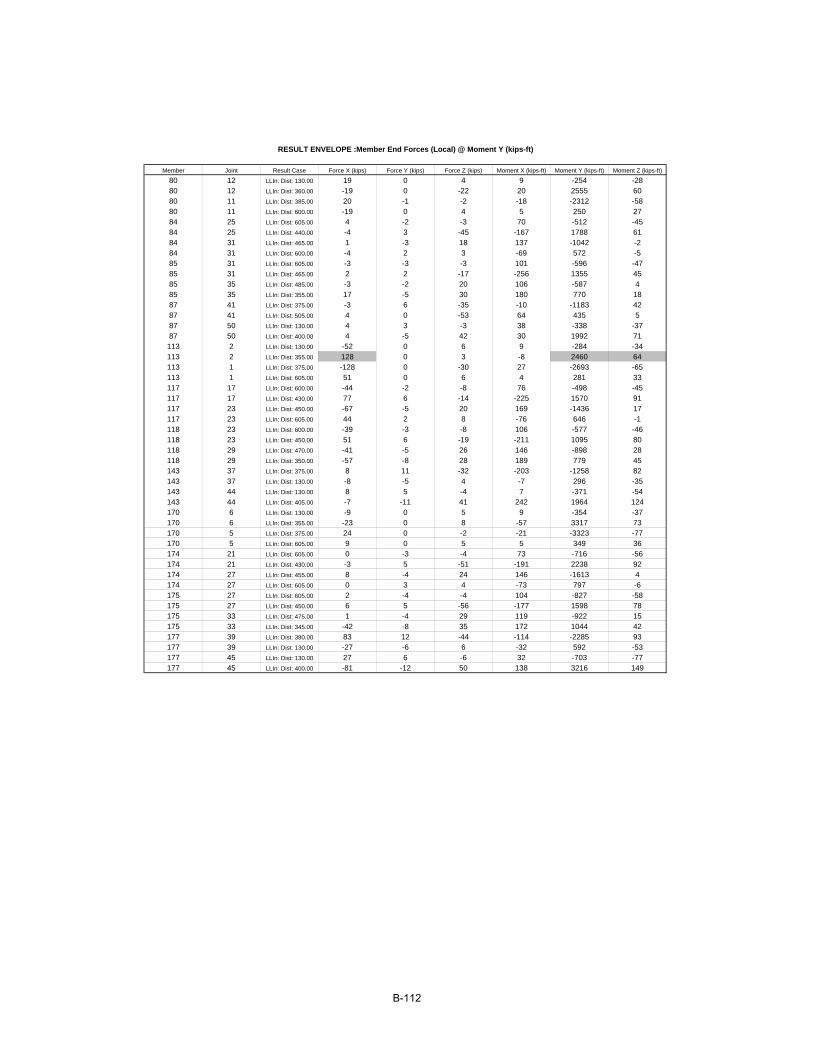
Member Joint Result Case Force X (kips) Force Y (kips) Force Z (kips) Moment X (kips-ft) Moment Y (kips-ft) Moment Z (kips-ft)
80 12 LLIn: Dist: 130.00 19 0 4 9 -254 -2880 12 LLIn: Dist: 360.00 -19 0 -22 20 2555 6080 11 LLIn: Dist: 385.00 20 -1 -2 -18 -2312 -5880 11 LLIn: Dist: 600.00 -19 0 4 5 250 2784 25 LLIn: Dist: 605.00 4 -2 -3 70 -512 -4584 25 LLIn: Dist: 440.00 -4 3 -45 -167 1788 6184 31 LLIn: Dist: 465.00 1 -3 18 137 -1042 -284 31 LLIn: Dist: 600.00 -4 2 3 -69 572 -585 31 LLIn: Dist: 605.00 -3 -3 -3 101 -596 -4785 31 LLIn: Dist: 465.00 2 2 -17 -256 1355 4585 35 LLIn: Dist: 485.00 -3 -2 20 106 -587 485 35 LLIn: Dist: 355.00 17 -5 30 180 770 1887 41 LLIn: Dist: 375.00 -3 6 -35 -10 -1183 4287 41 LLIn: Dist: 505.00 4 0 -53 64 435 587 50 LLIn: Dist: 130.00 4 3 -3 38 -338 -3787 50 LLIn: Dist: 400.00 4 -5 42 30 1992 71113 2 LLIn: Dist: 130.00 -52 0 6 9 -284 -34113 2 LLIn: Dist: 355.00 128 0 3 -8 2460 64113 1 LLIn: Dist: 375.00 -128 0 -30 27 -2693 -65113 1 LLIn: Dist: 605.00 51 0 6 4 281 33117 17 LLIn: Dist: 600.00 -44 -2 -8 76 -498 -45117 17 LLIn: Dist: 430.00 77 6 -14 -225 1570 91117 23 LLIn: Dist: 450.00 -67 -5 20 169 -1436 17117 23 LLIn: Dist: 605.00 44 2 8 -76 646 -1118 23 LLIn: Dist: 600.00 -39 -3 -8 106 -577 -46118 23 LLIn: Dist: 450.00 51 6 -19 -211 1095 80118 29 LLIn: Dist: 470.00 -41 -5 26 146 -898 28118 29 LLIn: Dist: 350.00 -57 -8 28 189 779 45143 37 LLIn: Dist: 375.00 8 11 -32 -203 -1258 82143 37 LLIn: Dist: 130.00 -8 -5 4 -7 296 -35143 44 LLIn: Dist: 130.00 8 5 -4 7 -371 -54143 44 LLIn: Dist: 405.00 -7 -11 41 242 1964 124170 6 LLIn: Dist: 130.00 -9 0 5 9 -354 -37170 6 LLIn: Dist: 355.00 -23 0 8 -57 3317 73170 5 LLIn: Dist: 375.00 24 0 -2 -21 -3323 -77170 5 LLIn: Dist: 605.00 9 0 5 5 349 36174 21 LLIn: Dist: 605.00 0 -3 -4 73 -716 -56174 21 LLIn: Dist: 430.00 -3 5 -51 -191 2238 92174 27 LLIn: Dist: 455.00 8 -4 24 146 -1613 4174 27 LLIn: Dist: 605.00 0 3 4 -73 797 -6175 27 LLIn: Dist: 605.00 2 -4 -4 104 -827 -58175 27 LLIn: Dist: 450.00 6 5 -56 -177 1598 78175 33 LLIn: Dist: 475.00 1 -4 29 119 -922 15175 33 LLIn: Dist: 345.00 -42 -8 35 172 1044 42177 39 LLIn: Dist: 380.00 83 12 -44 -114 -2285 93177 39 LLIn: Dist: 130.00 -27 -6 6 -32 592 -53177 45 LLIn: Dist: 130.00 27 6 -6 32 -703 -77177 45 LLIn: Dist: 400.00 -81 -12 50 138 3216 149
RESULT ENVELOPE :Member End Forces (Local) @ Moment Y (kips-ft)
B-112

Longitudinal Stresses: @ Midpoint of Span 2:
Table B-9 - Longitudinal Member Forces – Inside of Curve (LARSA Member 113)
Load Px (kips) My (ft.-kips) Mz (ft.-kips) DC 593 15,642 252 DW 116 3,027 49
PSFINAL 3,289 -11,180 -266 LLTRUCK + IM 128 2,460 64
LLLANE 217 2,897 115 DC+DW+PSFINAL 3,998 7,489 35
DC+DW+PSFINAL+LL+IM 4,343 12,846 214
Table B-10 - Longitudinal Member Forces – Outside of Curve (LARSA Member 80)
Load Px (kips) My (ft.-kips) Mz (ft.-kips) DC -4 14,846 257 DW -1 2,869 50
PSFINAL 3,696 -10,333 -268 LLTRUCK + IM -19 2,570 62
LLLANE -48 2,744 110 DC+DW+PSFINAL 3,691 7,382 39
DC+DW+PSFINAL+LL+IM 3,624 12,696 211 Live Loads adjusted by multiple presence factor and live load dynamic effect. Stress Calculation:
35.121566.4
1.554
12.27
===
=
t
yZTOP
x
yI
S
A
54.74434.7
1.554===
b
yZBOTTOM y
IS
51.3516.8
8.289===
outside
zYOUT x
IS where xoutside = 43/2 – 13.34 = 8.16
13.28967.0
8.289−=
−==
soffit
zYSOFFIT x
IS where xsoffit = 43/2 – 8.83 – 13.34 = -0.67
B-113
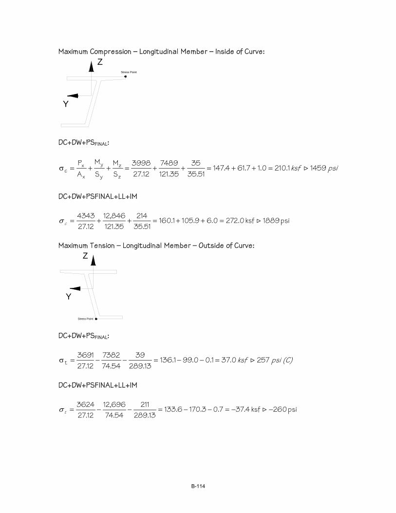
Maximum Compression – Longitudinal Member – Inside of Curve: Z
Y
Stress Point
DC+DW+PSFINAL:
psi ksf 14591.2100.17.614.14751.35
3535.121
748912.27
3998SM
SM
AP
z
z
y
y
x
xc >=++=++=++=σ
DC+DW+PSFINAL+LL+IM
psi 1889ksf 0.2720.69.1051.16051.35
21435.121
846,1212.27
4343>=++=++=cσ
Maximum Tension – Longitudinal Member – Outside of Curve:
Stress Point
Y
Z
DC+DW+PSFINAL:
(C) psi ksf 2570.371.00.991.13613.289
3954.74
738212.27
3691t >=−−=−−=σ
DC+DW+PSFINAL+LL+IM
psi 260ksf 4.377.03.1706.13313.289
21154.74
696,1212.27
3624−−=−−=−−= >tσ
B-114
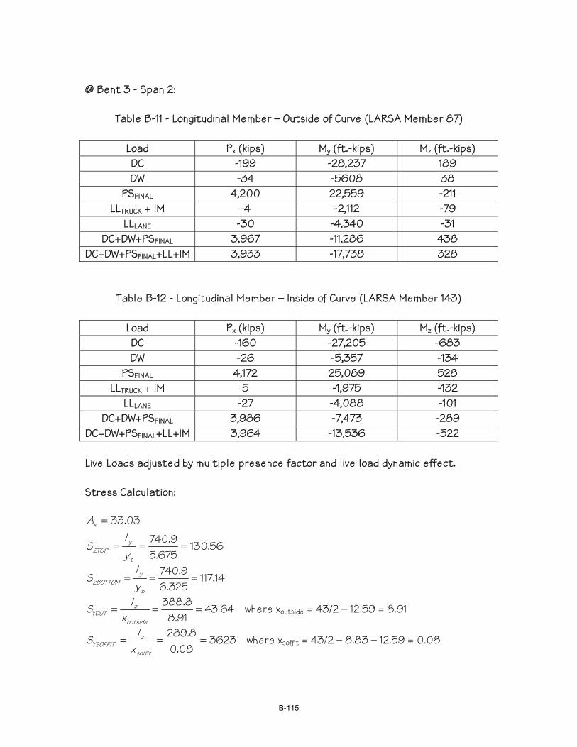
@ Bent 3 - Span 2:
Table B-11 - Longitudinal Member – Outside of Curve (LARSA Member 87)
Load Px (kips) My (ft.-kips) Mz (ft.-kips) DC -199 -28,237 189 DW -34 -5608 38
PSFINAL 4,200 22,559 -211 LLTRUCK + IM -4 -2,112 -79
LLLANE -30 -4,340 -31 DC+DW+PSFINAL 3,967 -11,286 438
DC+DW+PSFINAL+LL+IM 3,933 -17,738 328
Table B-12 - Longitudinal Member – Inside of Curve (LARSA Member 143)
Load Px (kips) My (ft.-kips) Mz (ft.-kips) DC -160 -27,205 -683 DW -26 -5,357 -134
PSFINAL 4,172 25,089 528 LLTRUCK + IM 5 -1,975 -132
LLLANE -27 -4,088 -101 DC+DW+PSFINAL 3,986 -7,473 -289
DC+DW+PSFINAL+LL+IM 3,964 -13,536 -522 Live Loads adjusted by multiple presence factor and live load dynamic effect. Stress Calculation:
56.130675.5
9.740
03.33
===
=
t
yZTOP
x
yI
S
A
14.117325.6
9.740===
b
yZBOTTOM y
IS
64.4391.8
8.388===
outside
zYOUT x
IS where xoutside = 43/2 – 12.59 = 8.91
362308.0
8.289===
soffit
zYSOFFIT x
IS where xsoffit = 43/2 – 8.83 – 12.59 = 0.08
B-115
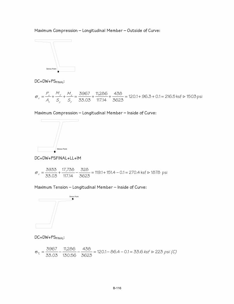
Maximum Compression – Longitudinal Member – Outside of Curve:
Stress Point DC+DW+PSFINAL:
psi 1503ksf 5.2161.03.961.1203623438
14.117286,11
03.333967
>=++=++=++=z
z
y
y
x
xc S
MSM
AP
σ
Maximum Compression – Longitudinal Member – Inside of Curve:
Stress Point
DC+DW+PSFINAL+LL+IM
psi 1878ksf 4.2701.04.1511.1193623328
14.117738,17
03.333933
>=−+=−+=cσ
Maximum Tension – Longitudinal Member – Inside of Curve:
Stress Point
DC+DW+PSFINAL:
(C) psi ksf 2236.331.04.861.1203623438
56.130286,11
03.333967
t >=−−=−−=σ
B-116
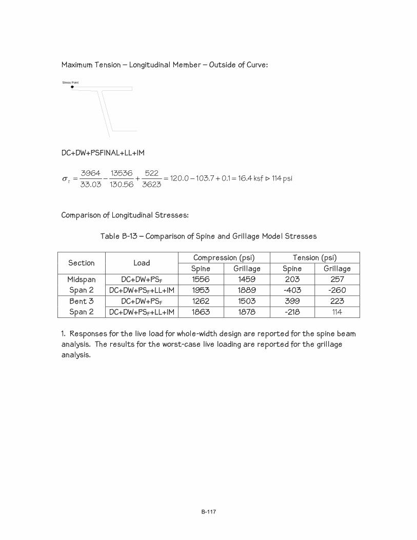
Maximum Tension – Longitudinal Member – Outside of Curve: Stress Point
DC+DW+PSFINAL+LL+IM
psi 114ksf 4.161.07.1030.1203623522
56.13013536
03.333964
>=+−=+−=tσ
Comparison of Longitudinal Stresses:
Table B-13 – Comparison of Spine and Grillage Model Stresses
Compression (psi) Tension (psi) Section Load
Spine Grillage Spine Grillage DC+DW+PSF 1556 1459 203 257 Midspan
Span 2 DC+DW+PSF+LL+IM 1953 1889 -403 -260 DC+DW+PSF 1262 1503 399 223 Bent 3
Span 2 DC+DW+PSF+LL+IM 1863 1878 -218 114 1. Responses for the live load for whole-width design are reported for the spine beam analysis. The results for the worst-case live loading are reported for the grillage analysis.
B-117
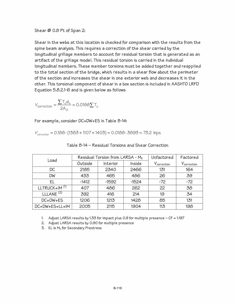
Shear @ 0.8 Pt of Span 2: Shear in the webs at this location is checked for comparison with the results from the spine beam analysis. This requires a correction of the shear carried by the longitudinal grillage members to account for residual torsion that is generated as an artifact of the grillage model. This residual torsion is carried in the individual longitudinal members. These member torsions must be added together and reapplied to the total section of the bridge, which results in a shear flow about the perimeter of the section and increases the shear in one exterior web and decreases it in the other. This torsional component of shear in a box section is included in AASHTO LRFD Equation 5.8.2.1-6 and is given below as follows
∑∑ == u0
sucorrection T0188.0
A2dT
V
For example, consider DC+DW+ES in Table B-14:
2.7338930188.0)140311071383(188.0 =⋅=++⋅=correctionV kips
Table B-14 – Residual Torsions and Shear Correction
Residual Torsion from LARSA - MX Load Outside Interior Inside
Unfactored Vcorrection
Factored Vcorrection
DC 2185 2340 2466 131 164 DW 433 465 486 26 39 EL -1412 -1592 -1524 -72 -72
LLTRUCK+IM (1) 407 486 262 22 38 LLLANE (2) 392 416 214 19 34 DC+DW+ES 1206 1213 1428 85 131
DC+DW+ES+LL+IM 2005 2115 1904 113 198
1. Adjust LARSA results by 1.33 for impact plus 0.9 for multiple presence – CF = 1.197 2. Adjust LARSA results by 0.90 for multiple presence 3. EL is MX for Secondary Prestress
B-118
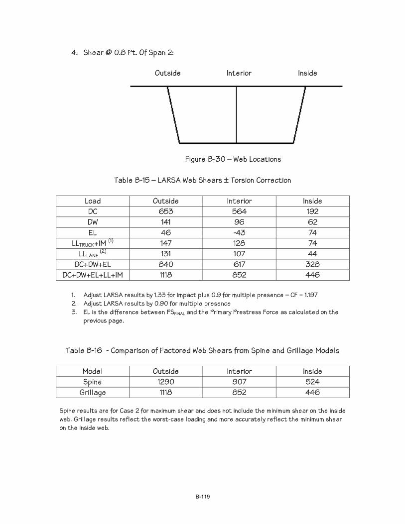
4. Shear @ 0.8 Pt. Of Span 2: Outside Interior Inside
Figure B-30 – Web Locations
Table B-15 – LARSA Web Shears ± Torsion Correction
Load Outside Interior Inside DC 653 564 192 DW 141 96 62 EL 46 -43 74
LLTRUCK+IM (1) 147 128 74 LLLANE
(2) 131 107 44 DC+DW+EL 840 617 328
DC+DW+EL+LL+IM 1118 852 446
1. Adjust LARSA results by 1.33 for impact plus 0.9 for multiple presence – CF = 1.197 2. Adjust LARSA results by 0.90 for multiple presence 3. EL is the difference between PSFINAL and the Primary Prestress Force as calculated on the
previous page.
Table B-16 - Comparison of Factored Web Shears from Spine and Grillage Models
Model Outside Interior Inside Spine 1290 907 524
Grillage 1118 852 446
Spine results are for Case 2 for maximum shear and does not include the minimum shear on the inside web. Grillage results reflect the worst-case loading and more accurately reflect the minimum shear on the inside web.
B-119
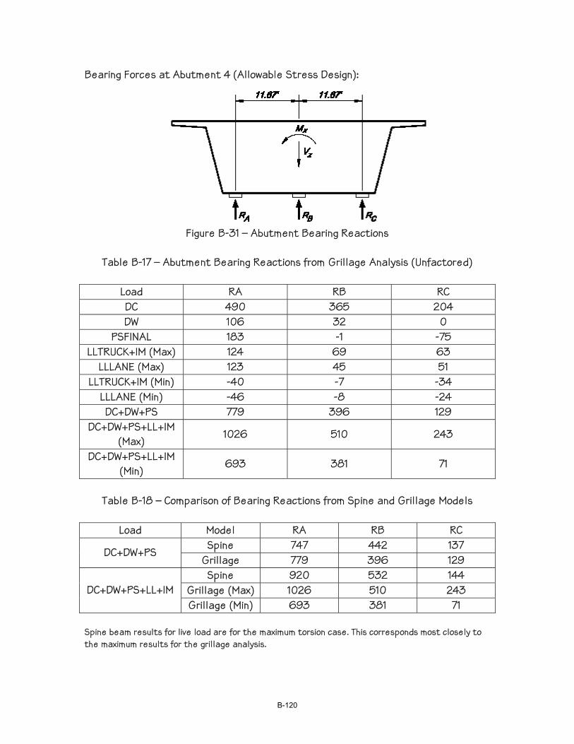
Bearing Forces at Abutment 4 (Allowable Stress Design):
Figure B-31 – Abutment Bearing Reactions
Table B-17 – Abutment Bearing Reactions from Grillage Analysis (Unfactored)
Load RA RB RC DC 490 365 204 DW 106 32 0
PSFINAL 183 -1 -75 LLTRUCK+IM (Max) 124 69 63
LLLANE (Max) 123 45 51 LLTRUCK+IM (Min) -40 -7 -34
LLLANE (Min) -46 -8 -24 DC+DW+PS 779 396 129
DC+DW+PS+LL+IM (Max)
1026 510 243
DC+DW+PS+LL+IM (Min)
693 381 71
Table B-18 – Comparison of Bearing Reactions from Spine and Grillage Models
Load Model RA RB RC
Spine 747 442 137 DC+DW+PS
Grillage 779 396 129 Spine 920 532 144
Grillage (Max) 1026 510 243 DC+DW+PS+LL+IM Grillage (Min) 693 381 71
Spine beam results for live load are for the maximum torsion case. This corresponds most closely to the maximum results for the grillage analysis.
B-120
EXAMPLE B-2 - TENDON CONFINEMENT EVALUATION
Introduction The primary purpose of the following numerical example is to demonstrate the recommended approach to evaluate a web without web and duct ties for tendon pull out and for tensile stresses on the cover concrete. This example also presents the application of a 2-d frame analysis of the box girder to determine the regional moments due to lateral prestress forces. Note that a frame analysis is not required by the specifications. The designer has the option of applying equation 5.10.4.3.1-6 to calculate amore conservative estimate of the regional moments. Construction Method The example problem assumes a continuous cast-in-place box girder constructed on falsework. Concrete Strength The example assumes a concrete strength of 3.5 ksi at transfer. In practice, the required strength will be dictated by design and local requirements. Post-tensioning System The prestress force, post-tensioning supplier, and the tendon arrangement were assumed for the purpose of demonstrating the procedure. In practice, the designer needs to consider permissible variations in prestress force between girders and a variety of tendon arrangements to determine the critical condition. Comments The following should be noted:
• The box girder is a fairly deep section (10'-6").
• The jacking force is relatively high (over 3400 kips per web).
• The radius is relatively large (3000-feet) and the resulting Fu-in of 1.4 k/ft is relatively small.
• The shear force exerted on the cover concrete is well below its capacity.
• The tensile stresses in the cover concrete due to combined local and regional bending are fairly high even though the radius is relatively large. This is due to the combination of the large number of bundled ducts and the large height of the webs. Transverse moments due to dead and live loads and the effects of construction tolerances, which can be significant, were ignored for this example.
• Note that the regional moments in the exterior webs are 9% higher than the interior web even though the interior web has a 4% higher prestress force.
B-121
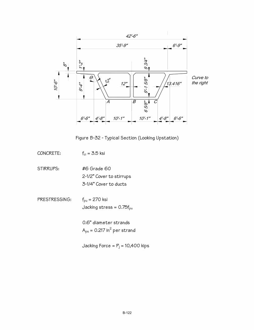
Figure B-32 - Typical Section (Looking Upstation)
CONCRETE: fci = 3.5 ksi STIRRUPS: #6 Grade 60 2-1/2” Cover to stirrups 3-1/4” Cover to ducts PRESTRESSING: fpu = 270 ksi Jacking stress = 0.75fpu 0.6” diameter strands Aps = 0.217 in2 per strand Jacking Force = Pj = 10,400 kips
B-122

Assumed Tendon Arrangement: Required number of strands = 10,400/(0.75 x 270 x 0.217) = 237 strands Assume (3) 26 – 0.6” tendons @ A & C - (4-1/2” duct) Assume (3) 27 – 0.6” tendons @ B - (4-1/2” duct) A or C Pj = 3 x 26 x 0.217 x 0.75 x 270 = 3428 kips B Pj = 3 x 27 x 0.217 x 0.75 x 270 = 3559 kips
Web A (C similar) Web B
Figure B-33 – Tendon Geometry at Webs
Table B-19 – Web Transverse Prestress Forces
Pj R Pj/R θ Pjcosθ/R Pjcosθ/Rhds Web kips ft kips/ft degrees kips/ft kips/in/ft
A 3428 3026.65 1.133 26.6 1.013 0.0763 B 3559 3014.5 1.181 0 1.181 0.0889 C 3428 3002.35 1.142 26.6 1.021 0.0769
B-123
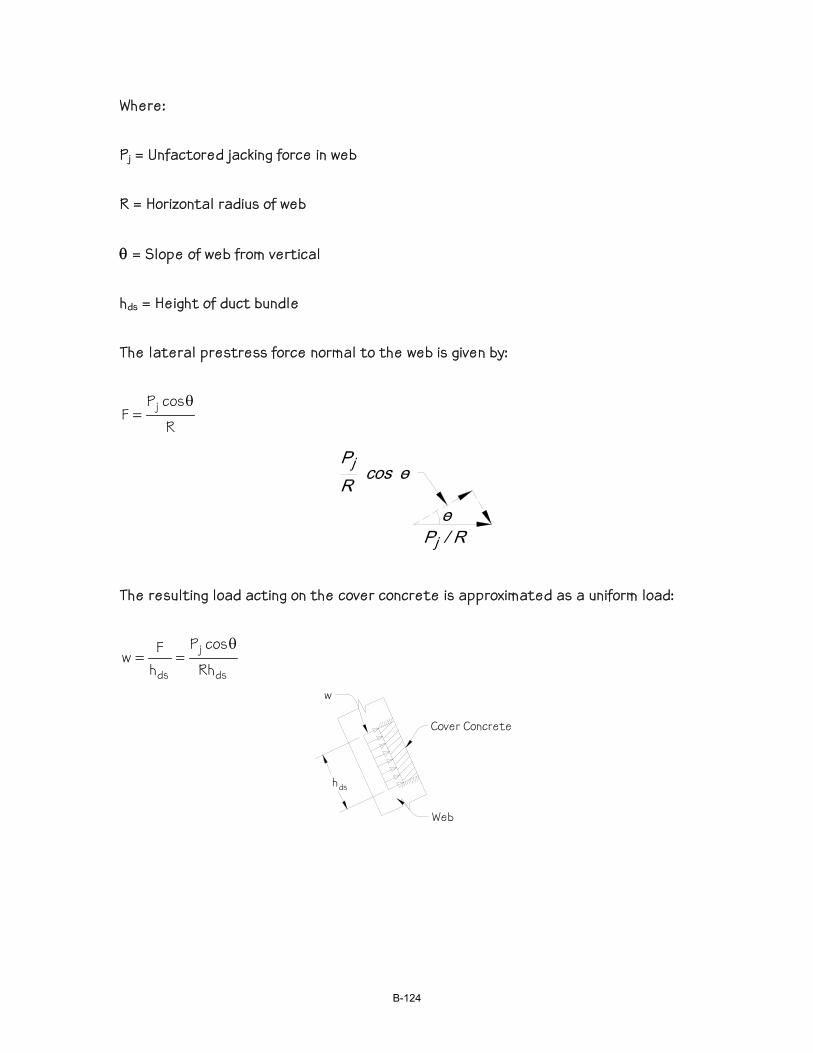
Where: Pj = Unfactored jacking force in web R = Horizontal radius of web
θ = Slope of web from vertical hds = Height of duct bundle The lateral prestress force normal to the web is given by:
R
cosPF j θ
=
The resulting load acting on the cover concrete is approximated as a uniform load:
ds
j
ds Rh
cosP
hFw
θ==
hds
Web
Cover Concrete
w
B-124
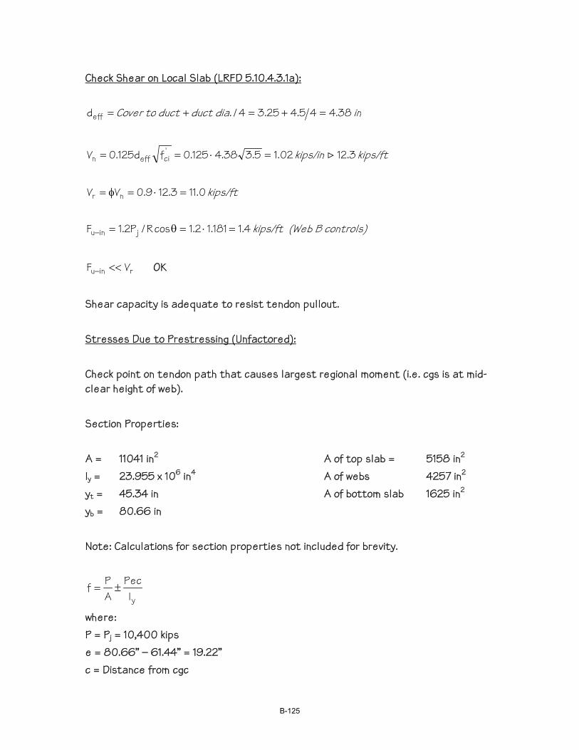
Check Shear on Local Slab (LRFD 5.10.4.3.1a):
in dia. ductduct to Cover 38.445.425.34/deff =+=+=
kips/ft kips/in 3.1202.15.338.4125.0fd125.0V 'cieffn >=⋅==
kips/ft 0.113.129.0VV nr =⋅=φ=
controls) B (Web kips/ft 4.1181.12.1cosR/P2.1F jinu =⋅=θ=−
rinu VF <<− OK
Shear capacity is adequate to resist tendon pullout. Stresses Due to Prestressing (Unfactored): Check point on tendon path that causes largest regional moment (i.e. cgs is at mid-clear height of web). Section Properties: A = 11041 in2 A of top slab = 5158 in2 Iy = 23.955 x 10⁶ in4 A of webs 4257 in2 yt = 45.34 in A of bottom slab 1625 in2 yb = 80.66 in Note: Calculations for section properties not included for brevity.
yIPec
APf ±=
where: P = Pj = 10,400 kips e = 80.66” – 61.44” = 19.22” c = Distance from cgc
B-125
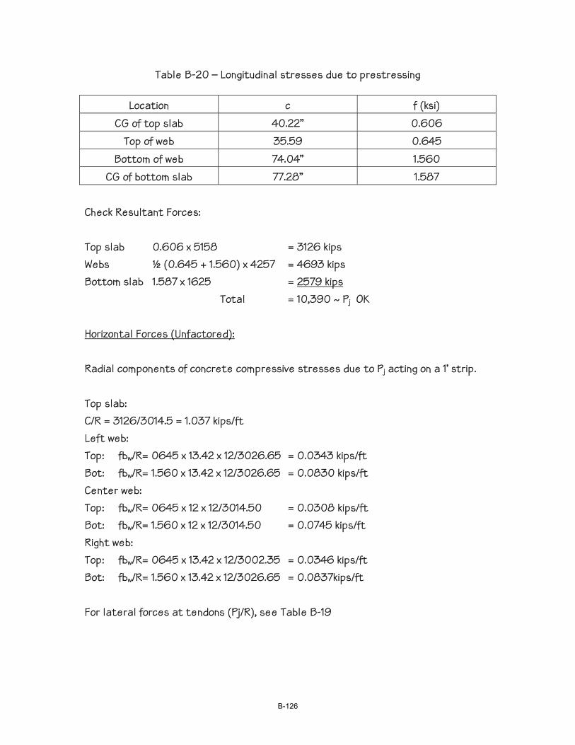
Table B-20 – Longitudinal stresses due to prestressing
Location c f (ksi) CG of top slab 40.22” 0.606
Top of web 35.59 0.645 Bottom of web 74.04” 1.560
CG of bottom slab 77.28” 1.587 Check Resultant Forces: Top slab 0.606 x 5158 = 3126 kips Webs ½ (0.645 + 1.560) x 4257 = 4693 kips Bottom slab 1.587 x 1625 = 2579 kips Total = 10,390 ~ Pj OK Horizontal Forces (Unfactored): Radial components of concrete compressive stresses due to Pj acting on a 1’ strip. Top slab: C/R = 3126/3014.5 = 1.037 kips/ft Left web: Top: fbw/R= 0645 x 13.42 x 12/3026.65 = 0.0343 kips/ft Bot: fbw/R= 1.560 x 13.42 x 12/3026.65 = 0.0830 kips/ft Center web: Top: fbw/R= 0645 x 12 x 12/3014.50 = 0.0308 kips/ft Bot: fbw/R= 1.560 x 12 x 12/3014.50 = 0.0745 kips/ft Right web: Top: fbw/R= 0645 x 13.42 x 12/3002.35 = 0.0346 kips/ft Bot: fbw/R= 1.560 x 13.42 x 12/3026.65 = 0.0837kips/ft For lateral forces at tendons (Pj/R), see Table B-19
B-126
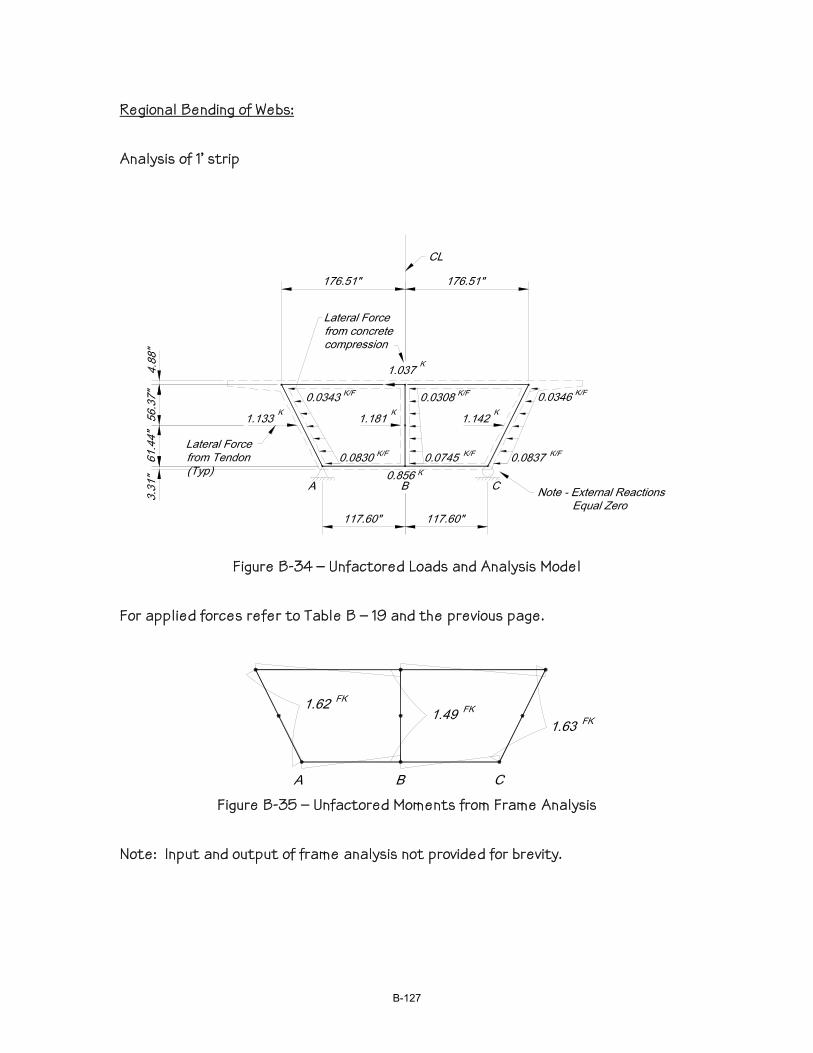
Regional Bending of Webs: Analysis of 1’ strip
Figure B-34 – Unfactored Loads and Analysis Model
For applied forces refer to Table B – 19 and the previous page.
Figure B-35 – Unfactored Moments from Frame Analysis
Note: Input and output of frame analysis not provided for brevity.
B-127
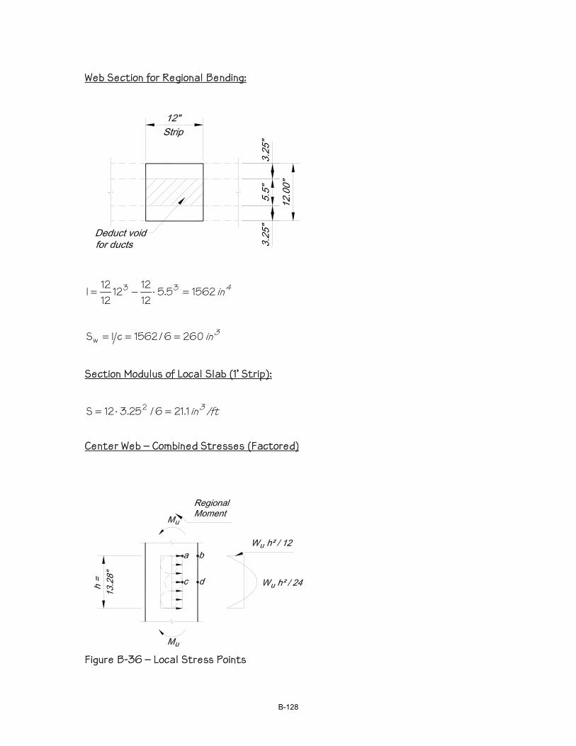
Web Section for Regional Bending:
4in 15625.5121212
1212I 33 =⋅−=
3in 2606/1562cISw ===
Section Modulus of Local Slab (1’ Strip):
/ftin 31.216/25.312S 2 =⋅= Center Web – Combined Stresses (Factored)
Figure B-36 – Local Stress Points
B-128
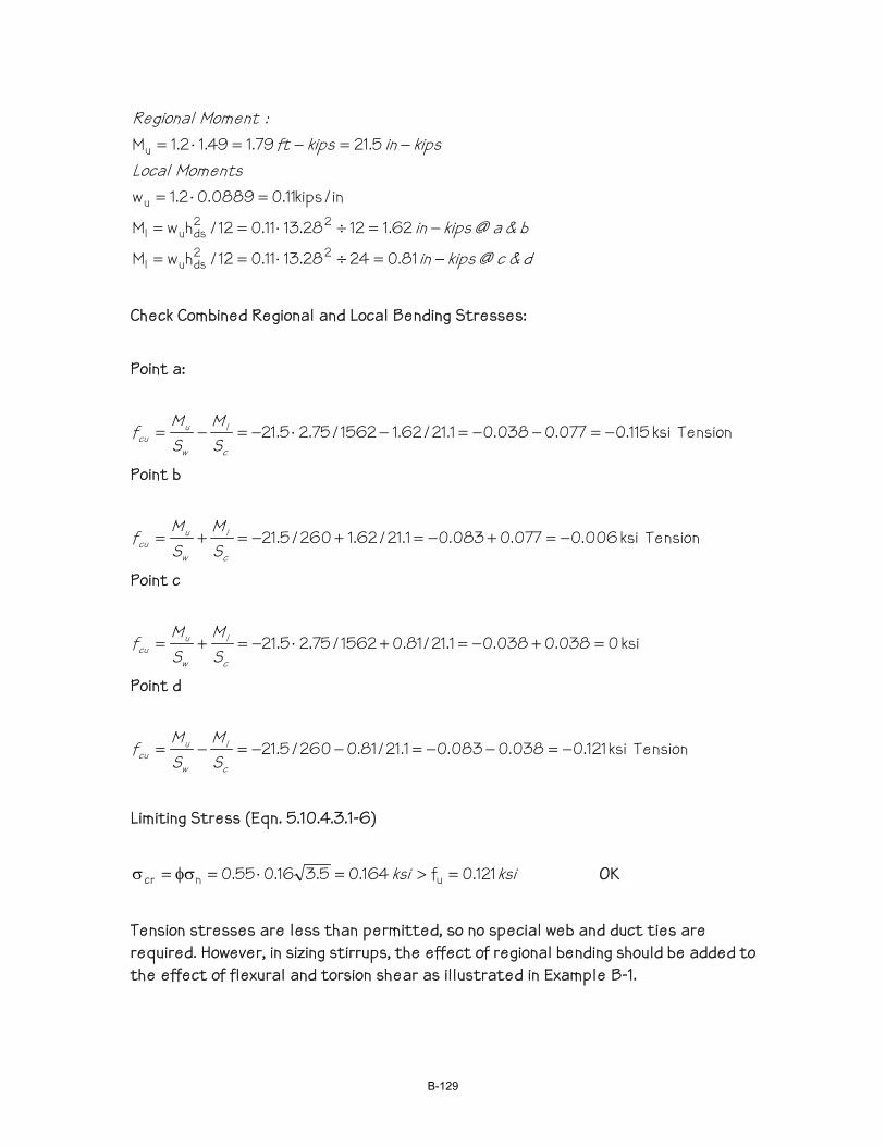
d&c @ kipsin
b&a @ kipsin
Moments Localkipsin kipsft
:Moment Regional
−=÷⋅==
−=÷⋅==
=⋅=
−=−=⋅=
81.02428.1311.012/hwM
62.11228.1311.012/hwM
in/kips11.00889.02.1w
5.2179.149.12.1M
22dsul
22dsul
u
u
Check Combined Regional and Local Bending Stresses: Point a:
Tension ksi 115.0077.0038.01.21/62.11562/75.25.21 −=−−=−⋅−=−=c
l
w
ucu S
MSMf
Point b
Tension ksi 006.0077.0083.01.21/62.1260/5.21 −=+−=+−=+=c
l
w
ucu S
MSMf
Point c
ksi 0038.0038.01.21/81.01562/75.25.21 =+−=+⋅−=+=c
l
w
ucu S
MSMf
Point d
Tension ksi 121.0038.0083.01.21/81.0260/5.21 −=−−=−−=−=c
l
w
ucu S
MSMf
Limiting Stress (Eqn. 5.10.4.3.1-6)
ksi ksi 121.0f164.05.316.055.0 uncr =>=⋅=φσ=σ OK
Tension stresses are less than permitted, so no special web and duct ties are required. However, in sizing stirrups, the effect of regional bending should be added to the effect of flexural and torsion shear as illustrated in Example B-1.
B-129

B-130

EXAMPLE B-3 - TENDON CONFINEMENT DESIGN Introduction
The primary purpose of the following numerical example is to demonstrate the recommended approach to design reinforcement for a web with web and duct ties.
Calculations are provided for the required steel area of the duct ties, web ties, and vertical stirrup leg on the inside of the curve. Local and regional effects were considered. Transverse moments due to dead and live loads and the effects of construction tolerances were ignored for this example. Global shear and torsion was not considered in the example but must be considered in actual designs.
Equation 5.10.4.3.1-6 was used to determine the regional web moment due to the lateral prestress forces. A 2-d frame analysis of the box girder would have resulted in smaller web moments as demonstrated in Example C-1
Construction Method
The example problem assumes a continuous cast-in-place box girder constructed on falsework.
Concrete Strength
The example assumes a concrete strength of 3.5 ksi at transfer and 4.0 ksi at 28 days. In practice, the required strength will be dictated by design and local requirements.
Post-tensioning System
The prestress force, post-tensioning supplier, and the tendon arrangement were assumed for the purpose of demonstrating the procedure. In practice, the designer needs to consider permissible variations in prestress force between girders and a variety of tendon arrangements to determine the critical condition.
Comments
The following should be noted:
• The box girder is a fairly deep section (9'-0").
• The jacking force is moderate (approximately 2700 kips per web).
• The radius is relatively small (650-feet) and the resulting Fu-in of 5.1 kips/ft per web is moderate.
• It is assumed that web and duct ties are required for the purpose of this example. Refer to Example C-1 for the recommended procedure to evaluate the need for web and duct ties.
B-131
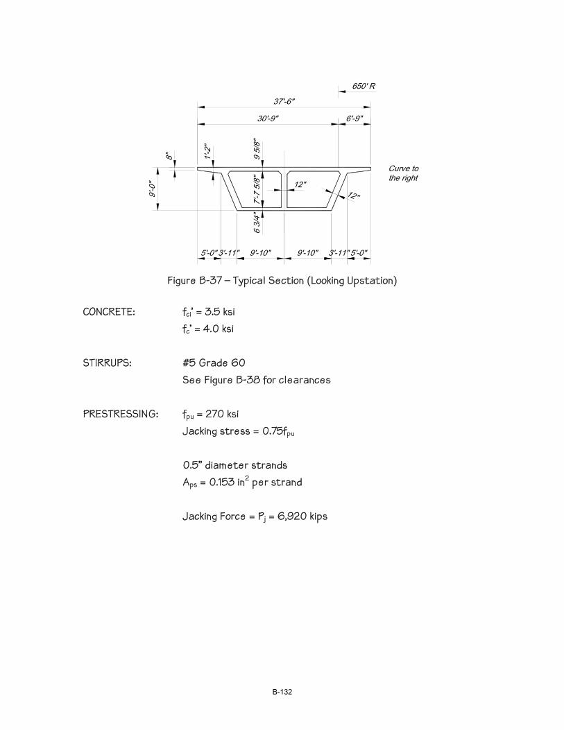
Figure B-37 – Typical Section (Looking Upstation)
CONCRETE: fci’ = 3.5 ksi fc’ = 4.0 ksi STIRRUPS: #5 Grade 60 See Figure B-38 for clearances PRESTRESSING: fpu = 270 ksi Jacking stress = 0.75fpu 0.5” diameter strands Aps = 0.153 in2 per strand Jacking Force = Pj = 6,920 kips
B-132
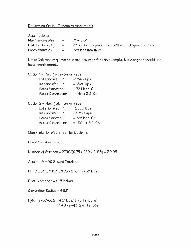
Determine Critical Tendon Arrangement: Assumptions: Max Tendon Size = 31 – 0.5” Distribution of Pj = 3:2 ratio max per Caltrans Standard Specifications Force Variation = 725 kips maximum Note: Caltrans requirements are assumed for this example, but designer should use local requirements Option 1 – Max Pj at exterior webs Exterior Web Pj =2548 kips Interior Web Pj = 1824 kips Force Variation = 724 kips OK Force Distribution = 1.4:1 < 3:2 OK Option 2 – Max Pj at interior webs Exterior Web Pj =2065 kips Interior Web Pj = 2790 kips Force Variation = 725 kips OK Force Distribution = 1.35:1 < 3:2 OK Check Interior Web Shear for Option 2: Pj = 2790 kips (max) Number of Strands = 2790/(0.75 x 270 x 0.153) = 30.05 Assume 3 – 30 Strand Tendons Pj = 3 x 30 x 0.153 x 0.75 x 270 = 2788 kips Duct Diameter = 4.13 inches Centerline Radius = 662’ Pj/R = 2788/662 = 4.21 kips/ft (3 Tendons) = 1.40 kips/ft (per Tendon)
B-133
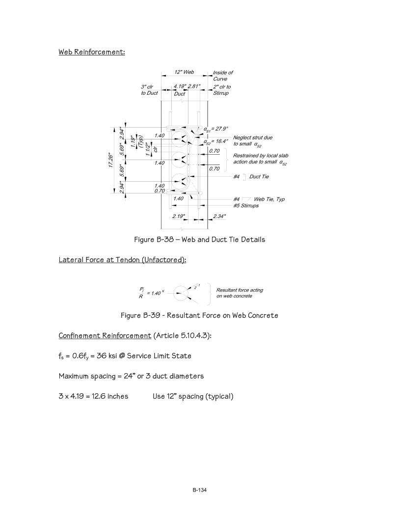
Web Reinforcement:
Figure B-38 – Web and Duct Tie Details
Lateral Force at Tendon (Unfactored):
Figure B-39 - Resultant Force on Web Concrete
Confinement Reinforcement (Article 5.10.4.3): fs = 0.6fy = 36 ksi @ Service Limit State Maximum spacing = 24” or 3 duct diameters 3 x 4.19 = 12.6 inches Use 12” spacing (typical)
B-134
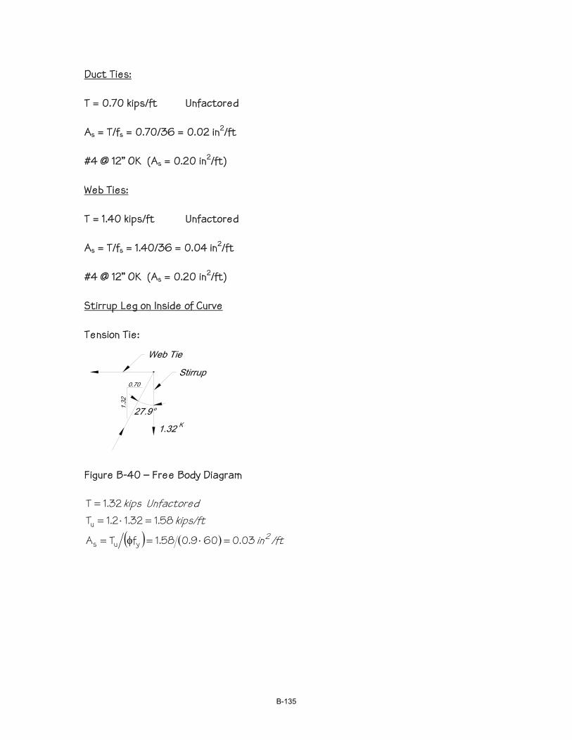
Duct Ties: T = 0.70 kips/ft Unfactored As = T/fs = 0.70/36 = 0.02 in2/ft #4 @ 12” OK (As = 0.20 in2/ft) Web Ties: T = 1.40 kips/ft Unfactored As = T/fs = 1.40/36 = 0.04 in2/ft #4 @ 12” OK (As = 0.20 in2/ft) Stirrup Leg on Inside of Curve Tension Tie:
Figure B-40 – Free Body Diagram
( ) ( ) /ftin
kips/ft Unfactored kips
203.0609.058.1fTA
58.132.12.1T32.1T
yus
u
=⋅=φ=
=⋅==
B-135
Local Bending of Cover Slab:
/ftin0.04 1.33A Use , 2.1
kips/ft ft43.312/3.46740.02.12.12.1in 3.466/81.412
ksi 740.0437.037.0
formulaeApproximat -/ft in 03.034.24/30.04
(Factored)kips/ft ft30.08/44.1)70.02(2.1
2s2
32
'
22
=>
−=⋅⋅===⋅=
===
=⋅=≈
−=⋅⋅≈
ucr
crcr
c
cr
Ends
End
MMSfM
Sff
dMAM
Regional Bending
Factored kips/ftft kips/ft −=⋅==− 05.521.42.1R/P2.1F jinu Use simplified method for determining regional moment (Eqn. 5.10.4.3.1-6)
kips/ftft −=⋅⋅=ψ≈ − 79.54/64.705.56.04/hFM inuu
( ) ( ) /ftin 215.066.94/79.5d4/MA u3s =⋅=≈
3in 2886/1212S 2c =⋅=
kips/ftft −=⋅⋅== 3.2112/288740.02.1Sf2.1M2.1 crcr
Use 1.33As3 = 0.20 in2/ft Total area of one stirrup leg (tendon confinement & bending) Tension tie = 0.03 Local bending = 0.04 Regional bending = 0.20 Subtotal = 0.27 in2/ft The above reinforcement does not include reinforcement for global shear and torsion. Refer to Article 5.8.1.5 for the reinforcement for combined effects.
B-136
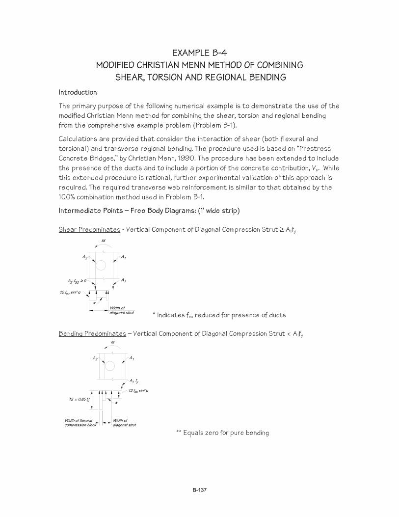
EXAMPLE B-4 MODIFIED CHRISTIAN MENN METHOD OF COMBINING
SHEAR, TORSION AND REGIONAL BENDING Introduction
The primary purpose of the following numerical example is to demonstrate the use of the modified Christian Menn method for combining the shear, torsion and regional bending from the comprehensive example problem (Problem B-1).
Calculations are provided that consider the interaction of shear (both flexural and torsional) and transverse regional bending. The procedure used is based on “Prestress Concrete Bridges,” by Christian Menn, 1990. The procedure has been extended to include the presence of the ducts and to include a portion of the concrete contribution, Vc. While this extended procedure is rational, further experimental validation of this approach is required. The required transverse web reinforcement is similar to that obtained by the 100% combination method used in Problem B-1.
Intermediate Points – Free Body Diagrams: (1’ wide strip) Shear Predominates - Vertical Component of Diagonal Compression Strut ≥ A1fy
* Indicates fcu reduced for presence of ducts Bending Predominates – Vertical Component of Diagonal Compression Strut < A1fy
** Equals zero for pure bending
B-137
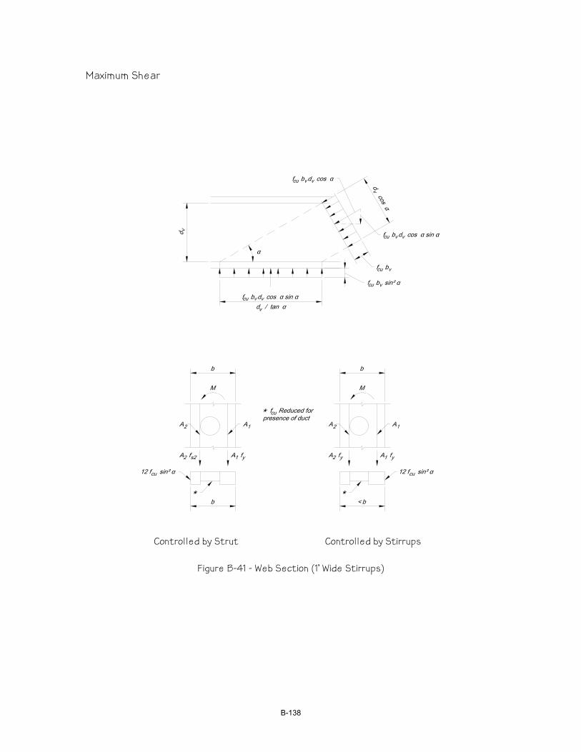
Maximum Shear
Controlled by Strut Controlled by Stirrups
Figure B-41 - Web Section (1’ Wide Stirrups)
B-138
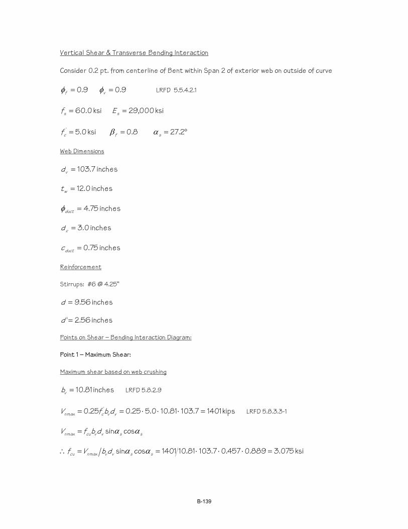
Vertical Shear & Transverse Bending Interaction Consider 0.2 pt. from centerline of Bent within Span 2 of exterior web on outside of curve
9.0=fφ 9.0=vφ LRFD 5.5.4.2.1
ksi 0.60=sf ksi 000,29=sE
ksi 0.5' =cf 8.0=fβ °= 2.27sα Web Dimensions
inches 7.103=vd
inches 0.12=wt
inches 75.4=ductφ
inches 0.3=cd
inches 75.0=ductc Reinforcement Stirrups: #6 @ 4.25”
inches 56.9=d
inches 56.2'=d Points on Shear – Bending Interaction Diagram: Point 1 – Maximum Shear: Maximum shear based on web crushing
inches 81.10=vb LRFD 5.8.2.9
kips 14017.10381.100.525.025.0 'max =⋅⋅⋅== vvcn dbfV LRFD 5.8.3.3-1
ssvvcun dbfV αα cossinmax =
ksi 075.3889.0457.07.10381.101401cossinmax =⋅⋅⋅==∴ ssvvncu dbVf αα
B-139

Maximum shear based on stirrups yielding
( ) ( ) kips 25069458.112
7.1030.6024.124.1cot21max =⋅⋅⋅+=+= svys dfAAV α
Controlling Case
kips 1401=nV Minimum of Vnmax and Vsmax
( ) ( ) kips/foot 4.839458.1127.1031401cot =⋅÷=svn dV α
Calculate Net Moment Capacity of Section Based on Concrete Compression and Steel Tension (See Figure B-40)
Force Component Width - in Force – kips
Moment Arm – in
F * Arm in-kips
Steel fs (ksi)
Cover on Compression Side of Tendon 3.00 23.1 1.50 34.7 Tendon 4.75 27.5 5.38 147.6 Cover on tension side of tendon 4.25 32.8 9.87 323.5 ∑ 83.4 505.8 Steel on tension face 74.5 9.56 712.6 60.0 Steel on compression face 8.8 2.56 22.6 7.1 ∑ 83.4 735.2 Interaction Points: Mn = (735.2 – 505.8)/12 = 19.12 ft-kips/foot Vn = 1401 kips Point 2 – Assumed Compression Block + Strut Width = Web Width Minus One-Half Tension Side Cover – Tension Face Steel Yields: Maximum force based on strut capacity
inches 88.9widthstrut block ncompressio Assumed =+
inches 69.8=effb
kips/ft 0.67457.0457.0075.369.812sin12 2max =⋅⋅⋅⋅== scueffn fbv α
Maximum force based on stirrups yielding
( ) ( ) kips/ft 1.1490.6024.124.121max =⋅+=+= ys fAAv
Controlling Case
B-140
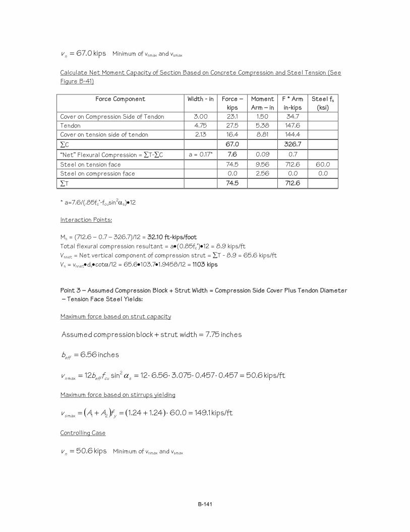
kips 0.67=nv Minimum of vnmax and vsmax
Calculate Net Moment Capacity of Section Based on Concrete Compression and Steel Tension (See Figure B-41)
Force Component Width - in Force – kips
Moment Arm – in
F * Arm in-kips
Steel fs (ksi)
Cover on Compression Side of Tendon 3.00 23.1 1.50 34.7 Tendon 4.75 27.5 5.38 147.6 Cover on tension side of tendon 2.13 16.4 8.81 144.4 ∑C 67.0 326.7 “Net” Flexural Compression = ∑T-∑C a = 0.17* 7.6 0.09 0.7 Steel on tension face 74.5 9.56 712.6 60.0 Steel on compression face 0.0 2.56 0.0 0.0 ∑T 74.5 712.6 * a=7.6/(.85fc’-fcusin2αs)•12 Interaction Points: Mn = (712.6 – 0.7 – 326.7)/12 = 32.10 ft-kips/foot Total flexural compression resultant = a•(0.85fc’)•12 = 8.9 kips/ft Vnnet = Net vertical component of compression strut = ∑T - 8.9 = 65.6 kips/ft Vn = vnnet•dv•cotα/12 = 65.6•103.7•1.9458/12 = 1103 kips Point 3 – Assumed Compression Block + Strut Width = Compression Side Cover Plus Tendon Diameter – Tension Face Steel Yields: Maximum force based on strut capacity
inches 75.7widthstrut block ncompressio Assumed =+
inches 56.6=effb
kips/ft 6.50457.0457.0075.356.612sin12 2max =⋅⋅⋅⋅== scueffn fbv α
Maximum force based on stirrups yielding
( ) ( ) kips/ft 1.1490.6024.124.121max =⋅+=+= ys fAAv
Controlling Case
kips 6.50=nv Minimum of vnmax and vsmax
B-141
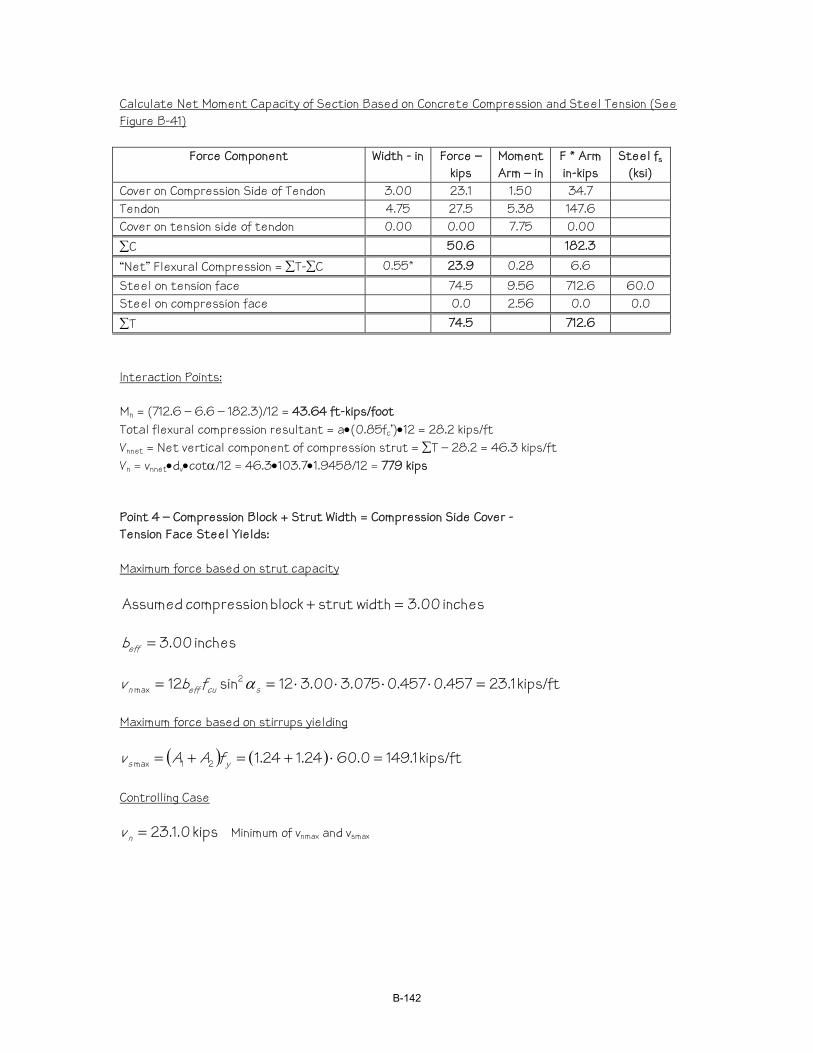
Calculate Net Moment Capacity of Section Based on Concrete Compression and Steel Tension (See Figure B-41)
Force Component Width - in Force – kips
Moment Arm – in
F * Arm in-kips
Steel fs (ksi)
Cover on Compression Side of Tendon 3.00 23.1 1.50 34.7 Tendon 4.75 27.5 5.38 147.6 Cover on tension side of tendon 0.00 0.00 7.75 0.00 ∑C 50.6 182.3 “Net” Flexural Compression = ∑T-∑C 0.55* 23.9 0.28 6.6 Steel on tension face 74.5 9.56 712.6 60.0 Steel on compression face 0.0 2.56 0.0 0.0 ∑T 74.5 712.6 Interaction Points: Mn = (712.6 – 6.6 – 182.3)/12 = 43.64 ft-kips/foot Total flexural compression resultant = a•(0.85fc’)•12 = 28.2 kips/ft Vnnet = Net vertical component of compression strut = ∑T – 28.2 = 46.3 kips/ft Vn = vnnet•dv•cotα/12 = 46.3•103.7•1.9458/12 = 779 kips Point 4 – Compression Block + Strut Width = Compression Side Cover - Tension Face Steel Yields: Maximum force based on strut capacity
inches 00.3widthstrut block ncompressio Assumed =+
inches 00.3=effb
kips/ft 1.23457.0457.0075.300.312sin12 2max =⋅⋅⋅⋅== scueffn fbv α
Maximum force based on stirrups yielding
( ) ( ) kips/ft 1.1490.6024.124.121max =⋅+=+= ys fAAv
Controlling Case
kips 0.1.23=nv Minimum of vnmax and vsmax
B-142
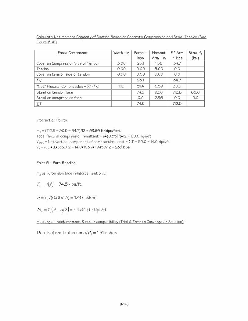
Calculate Net Moment Capacity of Section Based on Concrete Compression and Steel Tension (See Figure B-41)
Force Component Width - in Force – kips
Moment Arm – in
F * Arm in-kips
Steel fs (ksi)
Cover on Compression Side of Tendon 3.00 23.1 1.50 34.7 Tendon 0.00 0.00 3.00 0.0 Cover on tension side of tendon 0.00 0.00 3.00 0.0 ∑C 23.1 34.7 “Net” Flexural Compression = ∑T-∑C 1.19 51.4 0.59 30.5 Steel on tension face 74.5 9.56 712.6 60.0 Steel on compression face 0.0 2.56 0.0 0.0 ∑T 74.5 712.6 Interaction Points: Mn = (712.6 – 30.5 – 34.7)/12 = 53.95 ft-kips/foot Total flexural compression resultant = a•(0.85fc’)•12 = 60.0 kips/ft Vnnet = Net vertical component of compression strut = ∑T – 60.0 = 14.0 kips/ft Vn = vnnet•dv•cotα/12 = 14.0•103.7•1.9458/12 = 235 kips Point 5 – Pure Bending: Mn using tension face reinforcement only:
kips/ft 5.74== ysu fAT
inches 46.1)85.0/( ' == bfTa cu
( ) kips/ft- ft84.542 =−= adTM un
Mn using all reinforcement & strain compatibility (Trial & Error to Converge on Solution):
inches 91.1axis neutral of Depth 1 == βa
B-143
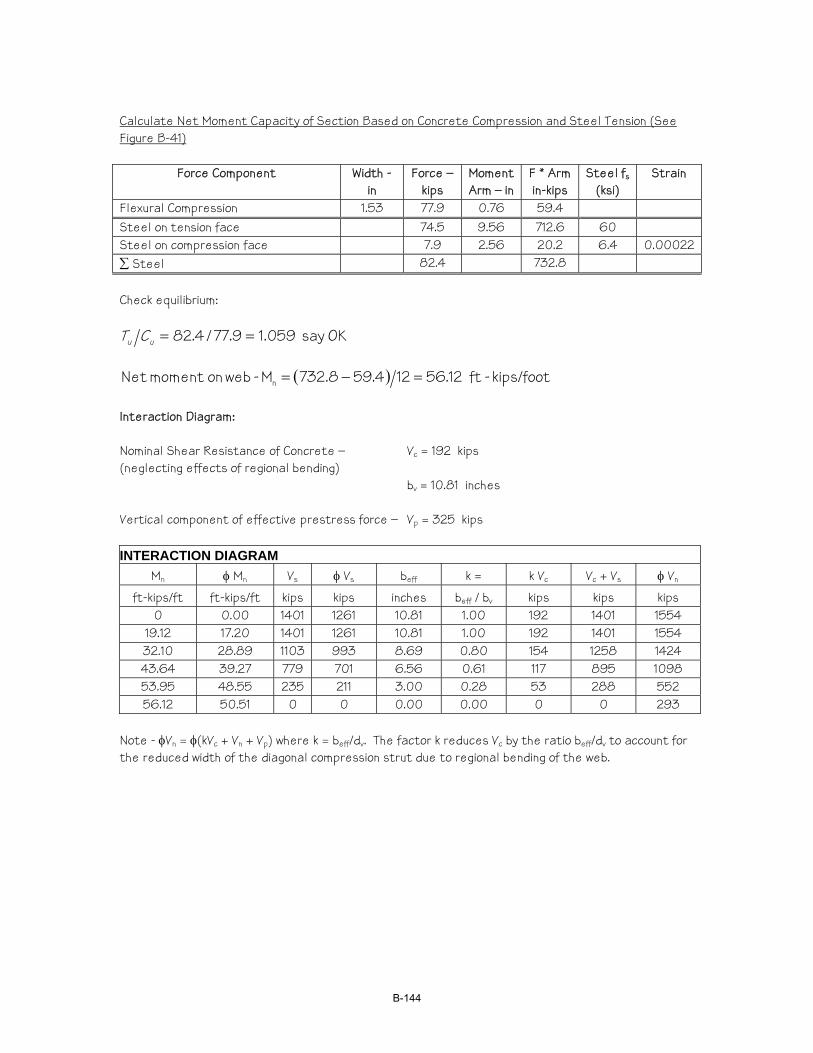
Calculate Net Moment Capacity of Section Based on Concrete Compression and Steel Tension (See Figure B-41)
Force Component Width - in
Force – kips
Moment Arm – in
F * Arm in-kips
Steel fs (ksi)
Strain
Flexural Compression 1.53 77.9 0.76 59.4 Steel on tension face 74.5 9.56 712.6 60 Steel on compression face 7.9 2.56 20.2 6.4 0.00022 ∑ Steel 82.4 732.8 Check equilibrium:
OKsay 059.19.77/4.82 ==uu CT
( ) kips/foot- ft12.56124.598.732M - web onmoment Net n =−=
Interaction Diagram: Nominal Shear Resistance of Concrete – Vc = 192 kips (neglecting effects of regional bending) bv = 10.81 inches Vertical component of effective prestress force – Vp = 325 kips INTERACTION DIAGRAM
Mn φ Mn Vs φ Vs beff k = k Vc Vc + Vs φ Vn
ft-kips/ft ft-kips/ft kips kips inches beff / bv kips kips kips 0 0.00 1401 1261 10.81 1.00 192 1401 1554
19.12 17.20 1401 1261 10.81 1.00 192 1401 1554 32.10 28.89 1103 993 8.69 0.80 154 1258 1424 43.64 39.27 779 701 6.56 0.61 117 895 1098 53.95 48.55 235 211 3.00 0.28 53 288 552 56.12 50.51 0 0 0.00 0.00 0 0 293
Note - φVn = φ(kVc + Vn + Vp) where k = beff/dv. The factor k reduces Vc by the ratio beff/dv to account for the reduced width of the diagonal compression strut due to regional bending of the web.
B-144
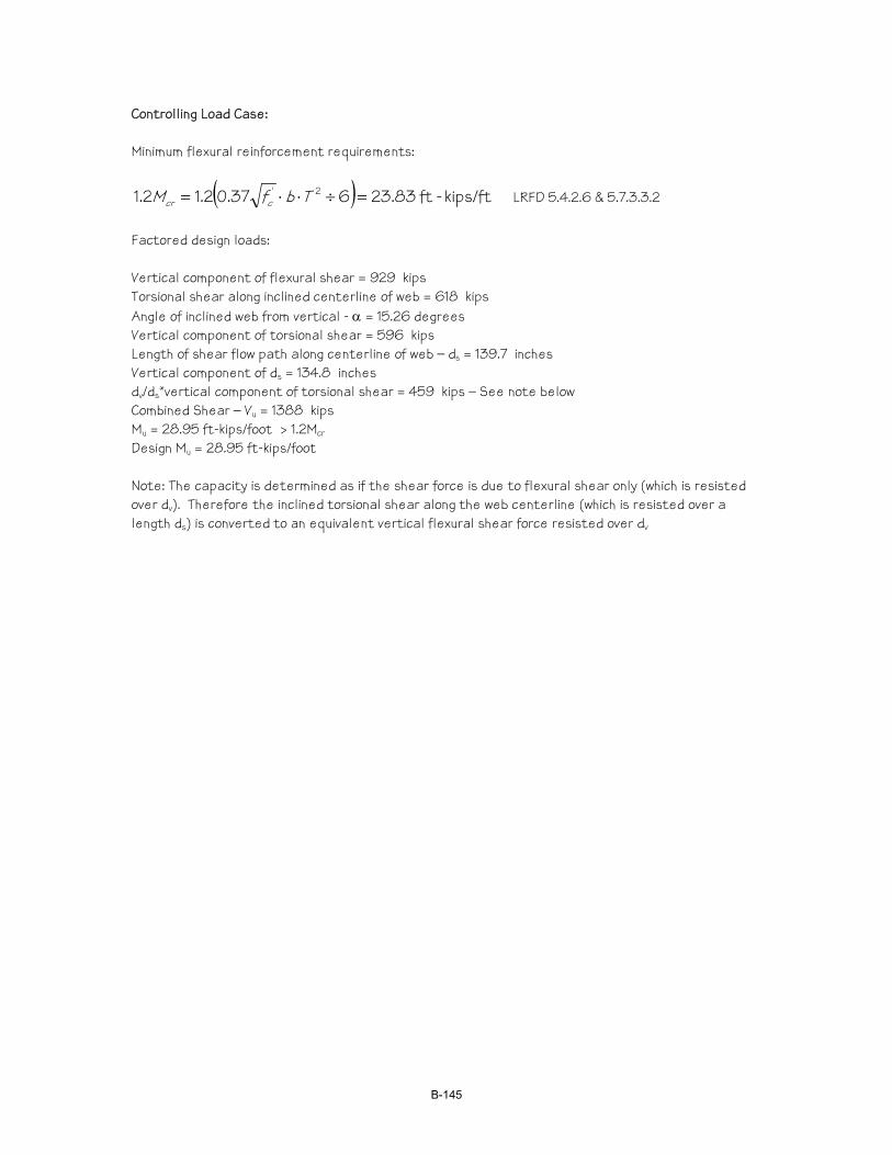
Controlling Load Case: Minimum flexural reinforcement requirements:
( ) kips/ft- ft83.23637.02.12.1 2' =÷⋅⋅= TbfM ccr LRFD 5.4.2.6 & 5.7.3.3.2
Factored design loads: Vertical component of flexural shear = 929 kips Torsional shear along inclined centerline of web = 618 kips Angle of inclined web from vertical - α = 15.26 degrees Vertical component of torsional shear = 596 kips Length of shear flow path along centerline of web – ds = 139.7 inches Vertical component of ds = 134.8 inches dv/ds*vertical component of torsional shear = 459 kips – See note below Combined Shear – Vu = 1388 kips Mu = 28.95 ft-kips/foot > 1.2Mcr Design Mu = 28.95 ft-kips/foot Note: The capacity is determined as if the shear force is due to flexural shear only (which is resisted over dv). Therefore the inclined torsional shear along the web centerline (which is resisted over a length ds) is converted to an equivalent vertical flexural shear force resisted over dv
B-145
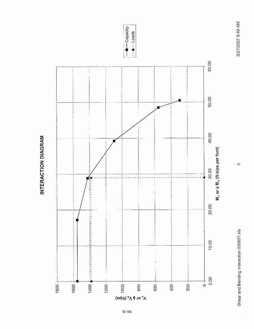
B-146
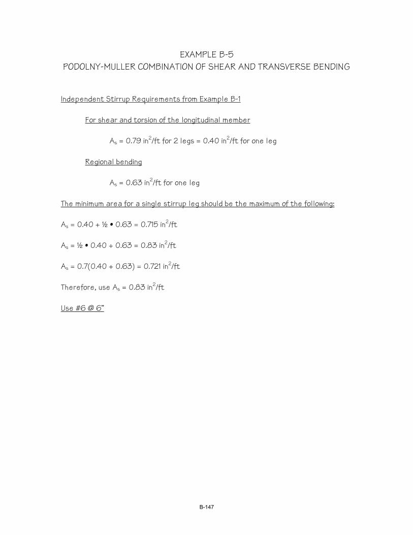
EXAMPLE B-5 PODOLNY-MULLER COMBINATION OF SHEAR AND TRANSVERSE BENDING
Independent Stirrup Requirements from Example B-1
For shear and torsion of the longitudinal member
As = 0.79 in2/ft for 2 legs = 0.40 in2/ft for one leg
Regional bending
As = 0.63 in2/ft for one leg The minimum area for a single stirrup leg should be the maximum of the following: As = 0.40 + ½ • 0.63 = 0.715 in2/ft As = ½ • 0.40 + 0.63 = 0.83 in2/ft As = 0.7(0.40 + 0.63) = 0.721 in2/ft Therefore, use As = 0.83 in2/ft Use #6 @ 6”
B-147

B-148
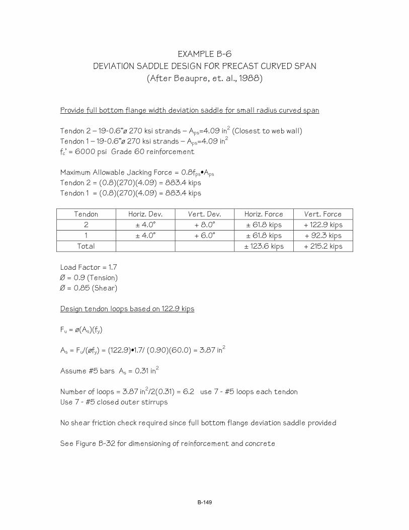
EXAMPLE B-6 DEVIATION SADDLE DESIGN FOR PRECAST CURVED SPAN
(After Beaupre, et. al., 1988)
Provide full bottom flange width deviation saddle for small radius curved span Tendon 2 – 19-0.6”ø 270 ksi strands – Aps=4.09 in2 (Closest to web wall) Tendon 1 – 19-0.6”ø 270 ksi strands – Aps=4.09 in2 fc’ = 6000 psi Grade 60 reinforcement Maximum Allowable Jacking Force = 0.8fps•Aps Tendon 2 = (0.8)(270)(4.09) = 883.4 kips Tendon 1 = (0.8)(270)(4.09) = 883.4 kips
Tendon Horiz. Dev. Vert. Dev. Horiz. Force Vert. Force 2 ± 4.0˚ + 8.0˚ ± 61.8 kips + 122.9 kips 1 ± 4.0˚ + 6.0˚ ± 61.8 kips + 92.3 kips
Total ± 123.6 kips + 215.2 kips Load Factor = 1.7 Ø = 0.9 (Tension) Ø = 0.85 (Shear) Design tendon loops based on 122.9 kips Fu = ø(As)(fy) As = Fu/(øfy) = (122.9)•1.7/ (0.90)(60.0) = 3.87 in2 Assume #5 bars As = 0.31 in2 Number of loops = 3.87 in2/2(0.31) = 6.2 use 7 - #5 loops each tendon Use 7 - #5 closed outer stirrups No shear friction check required since full bottom flange deviation saddle provided See Figure B-32 for dimensioning of reinforcement and concrete
B-149
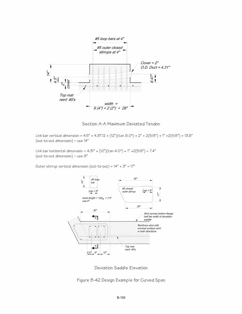
Section A-A Maximum Deviated Tendon
Link bar vertical dimension = 4.5” + 4.31”/2 + (12”)(tan 8.0º) + 2” + 2(5/8”) + 1” +2(5/8”) = 13.8” (out-to-out dimension) – use 14” Link bar horizontal dimension = 4.31” + (12”)(tan 4.0º) + 1” +2(5/8”) = 7.4” (out-to-out dimension) – use 8” Outer stirrup vertical dimension (out-to-out) = 14” + 3” = 17”
Deviation Saddle Elevation
Figure B-42 Design Example for Curved Span
B-150