appendix b electrical distribution system safety rules … · electrical distribution system safety...
TRANSCRIPT

Note - This document may have been superseded by a more recent version. Please check on the SHE website for the most up-to-date version of this document.
Issue Number: 1.3 Issue Date: 29/01/2020 Author: Various Page 30 of 97
Appendix B ELECTRICAL DISTRIBUTION SYSTEM SAFETY RULES AND PROCEDURES
B1 ALLOCATION OF RESPONSIBILITIES BETWEEN THE STFC AND OTHERS General B1.1 Where there is a division of electrical responsibilities between the STFC and others
working on STFC sites, such as contractors or electrical suppliers, the STFC Authorising Engineer or Authorised Person (Electrical) shall co-operate and co-ordinate with the other party (or parties) as necessary to prevent injury.
B1.2 The STFC Authorised Person (Electrical) shall not exceed their areas of responsibility as defined by their letter of appointment.
B1.3 In the clauses that follow, each demarcation of responsibility is to be recorded in writing and precisely described by a diagram. The Demarcation Line is to be at a cable termination and should normally be at the outgoing terminals of a switch or circuit breaker, which shall remain under the control of the controlling authority.
Where STFC has Control of the Electrical Hazards B1.4 The STFC owns and is responsible for the safe installation, operation and
maintenance of all electrical systems on its sites and those working on them. STFC personnel and others are to work in accordance with this SHE Code.
Where STFC does not have Control of the Electrical Hazards B1.5 STFC has the general duty of care that is imposed by the Health and Safety at Work
etc. Act 1974. The organisation or person having control of the electrical hazard is responsible for ensuring the safety of all persons on site and is required to operate a safe system of work by the Electricity at Work Regulations, 1989. This means, that even where STFC transfers control to another body, such as under a Certificate of Transfer of Control (see section B14), there is still a responsibility upon STFC to ensure work is carried out to a standard, that as a minimum, complies with this SHE Code.
Where STFC Appoints an Electrical Contractor B1.6 STFC is to specify in the conditions of contract that the contractor shall comply with
this SHE Code. B1.7 The STFC Authorising Engineer (Electrical) may, where appropriate, appoint non-
STFC Authorised Persons (Electrical) to work on STFC electrical systems. B1.8 In certain cases, for example under a contract, the contractor may be allowed to
adopt their own safe system of work subject to approval by the STFC Authorising Engineer (Electrical) responsible for the area of work. A copy of such rules shall be sent to the Authorising Engineer (Electrical) a minimum of 1 month prior to the start of the contract so that any anomalies can be corrected prior to the commencement of work. Any subsequent changes to the Contractors’ system of work must be approved by the STFC Authorising Engineer (Electrical).
B1.9 Where the Contractor is to take responsibility for part of a system or installation connected to the STFC system, a Certificate of Transfer of Control shall be issued (see Section B14). The exact extent of the responsibilities of all parties shall be shown on the certificate and on associated drawings, and shall show clearly all Demarcation Lines. This Certificate, including the conditions of issue, must be agreed by the project manager before issuing to the contractor.
Note - This document may have been superseded by a more recent version. Please check on the SHE website for the most up-to-date version of this document.
Issue Number: 1.3 Issue Date: 29/01/2020 Author: Various Page 31 of 97
B1.10 For acceptance of a new electrical system, see Section B25.
Where STFC Provides a Temporary Electricity Supply to another Consumer or Contractor B1.11 The temporary supply is to include a means of isolation under the control of STFC.
The supply terminals of the temporary supply are to be the outgoing terminals of a switch dis-connector, circuit breaker, or other clearly identified terminals. (See section B21)
B1.12 STFC is to be responsible for the control of the system up to and including the supply terminals. The consumer is to be responsible for the connections to the terminals and for the remainder of the downstream system.
B1.13 Where Temporary Supplies are under the control of contractors it shall be the responsibility of the contractor to provide monthly test certificates to a nominated person at STFC.
B1.14 Failure to comply with Clause B1.13 may result in a disconnection of supply by STFC.
B2 WORKING ON AND TESTING LOW VOLTAGE EQUIPMENT General B2.1 This SHE Code does not apply where low voltage equipment has been discharged,
disconnected, removed from the system or installation and is not energised by other means.
B2.2 Low voltage equipment that is considered by the Authorised Person (Electrical) to be in a dangerous condition is to be isolated elsewhere and action taken by the Authorised Person (Electrical) to prevent it being re-connected to the supply of electricity. The Authorised Person (Electrical) is to report the matter as soon as reasonably practicable to the Authorising Engineer (Electrical).
B2.3 Unless the provision of Section B11 apply, all working on or testing of low voltage equipment connected to a system is to follow the procedures set out in Tables LV1, LV2 or LV3 of this SHE Code as appropriate. An Authorised Person (Electrical) or Nominated Person following the procedures set out in Table LV3 becomes the Person in Charge and is responsible for the Work or Test.
B2.4 The Authorising Engineer can issue an exemption to a Nominated Person to switch, operate and make safe equipment on the load side of a main intake switch rated above 100A provided that a suitable risk assessment has been completed and the specific exemption is detailed on the Nominated Person’s letter of appointment.
B2.5 Safety Locks are to be applied wherever practicable at points of isolation to prevent unauthorised operation or re-connection. Voltage Test Indicators are to be tested immediately before and after use against a Test Supply (proving unit).
B2.6 A low voltage test devices should comply with the recommendations of GS38 – Electrical Test Equipment for use by Electrician, published by the Health and Safety Executive and/or BS EN 61243/IEC 61243 as appropriate. Test Indicators for use in 230/400 volts systems should be suitable and sufficient for use up to 500 volts and should indicate a live supply down to 50 volts. (Voltage indicators with integral fuses are prohibited for future purchases)
B2.7 Multifunction instruments, single contact neon indicators, or non-contact indicators shall not be used to prove dead at Low Voltage.
B2.8 A proving unit is the recommended method for verifying the functionality of a Voltage Test Indicator; they must be designed for use with two pole voltage testing devices, examples of compliant units are Martindale PD700, Megger MPU690 and Kewtech Kewprove3. A known live ac supply can be used for verification in extreme cases, if voltages above ELV are protected to a minimum of IP2X.
Note - This document may have been superseded by a more recent version. Please check on the SHE website for the most up-to-date version of this document.
Issue Number: 1.3 Issue Date: 29/01/2020 Author: Various Page 32 of 97
B2.9 Equipment and conductors are to be proved dead prior to the application of any
temporary earth and removable temporary earth. Where it is not practicable to prove dead other means are to be used to make an assessment that the Equipment and conductors to which the earth is to be applied are not energised, then any temporary earth and removable temporary earth connections shall be made by means of a switch, or circuit breaker with integral earthing facilities, that form part of the permanently installed equipment. Other forms of temporary earth or removable temporary earth connection shall not be used until the conductor, where the earth is to be applied, has been proved dead.
B2.10 Where the procedures involve the application of Temporary Earths the unauthorised removal of such earth connections is to be prevented wherever practicable by the application of Safety Locks. These Safety Locks are, where practicable, to be in addition to those required by Clause B2.4.
B2.11 Where the procedures involve the application of Removable Temporary Earths the unauthorised removal of such earth connections is to be prevented, wherever practicable, by the application of an Earthing Lock. The key of the Earthing Lock is to be issued to the Person in Charge who will retain control of it for the duration of the tests (see Clauses B19.9 to B19.11).
B2.12 Prior to the issue of a Permit to Work or Sanction to Test, the Authorised Person (Electrical) is to show the prospective Person in Charge the electrical diagram on the Safety Programme, the safety arrangements at the points of isolation and at the places of work or test and is to ensure that the person understands all the relevant safety procedures and precautions. After accepting the Permit to Work or Sanction to Test the Authorised or Nominated person becomes the Person in Charge and is responsible for the defined Work or Test until the Permit or Sanction is cancelled.
Where a Permit to Work or Sanction to Test is not required and isolation is achieved by the removal of fuses or links and it is not practicable to apply a Safety Lock, then the fuses or links are to be removed and securely retained in the possession of the Authorise Person (Electrical) or Nominated Person responsible for the work or test, and a caution notice posted at the point of isolation.

Note - This document may have been superseded by a more recent version. Please check on the SHE website for the most up-to-date version of this document.
Issue Number: 1.3 Issue Date: 29/01/2020 Author: Various Page 33 of 97
Table LV1 for Working on Low Voltage Equipment Except where a Risk Assessment indicates that an explosion, electric shock or possibility of short circuit exists, equipment operating at Extra Low Voltage is exempt from these procedures. Steps in column 1 are to be undertaken in numerical order. Columns 2, 3 and 4 provide detail for the specified Equipment. The Authorised Person (Electrical) is to be in possession of a current Authorised Person’s (Electrical) letter of Appointment appropriate to the equipment being worked on, and is responsible for Steps 1, 2, 3, 4, 5, and 7, 8, 9, 10, 11. The Person in Charge is to be in possession of a current Nominated Person’s letter of Appointment appropriate to the equipment being worked on, and is responsible for Step 6. COLUMN 1 COLUMN 2 COLUMN 3 COLUMN 4 EQUIPMENT Main intake switches,
switchboards and Equipment having two or more sources of supply, cables and other Equipment on the supply side of a main intake switch, and all underground cables, street lighting circuits, and supplies rated at 100A or more. (If equipment has two sources of supply and one is for controls / instrumentation only, see Column 2 of Table LV3)
Generating sets started by manual initiation from a remote location, or automatically on receipt of a signal.
Uninterruptible Power Supply Equipment. If a battery system has a maximum series chain/string voltage exceeding 120 volts dc a Sanction to Work should be completed, unless isolators have been provided to allow the string voltage to be reduced to below 120 volts dc.
STEP 1: PREPARE SAFETY PROGRAMME
COMPLY WITH ANY PARTICULAR SAFETY PROCEDURES APPLICABLE TO THE LOCATION. Prepare a Safety Programme and obtain a countersignature before proceeding to step 2, unless B8.2 applies.
STEP 2: ISOLATE AND FIX SIGNS
ISOLATE FROM ALL SOURCES OF SUPPLY. Prevent unauthorised connection or unauthorised operation by fixing Safety Locks and Caution Notices at all the points of isolation. Fix Caution Notices on motor starting Equipment. Fix Electrical Equipment Warning Signs on adjacent live Equipment at the places of the work. The need to isolate
INHIBIT ENGINE START, ISOLATE GENERATOR. Prevent unauthorised connection, or unauthorised operation or unauthorised starting by fixing Safety Locks. Fix Caution Notices at all the points of isolation and on the engine start panel. Fix Electrical Equipment Warning Signs on adjacent live Equipment.
ISOLATE FROM ALL SOURCES OF SUPPLY. Isolate mains supply, battery supply, output supply and any standby power supply. On parallel Uninterruptible Power Supply systems and those having an external bypass, ISOLATE the output supply terminal of the units being worked on

Note - This document may have been superseded by a more recent version. Please check on the SHE website for the most up-to-date version of this document.
Issue Number: 1.3 Issue Date: 29/01/2020 Author: Various Page 34 of 97
neutral conductors should be assessed on each job and should be stated on the permit whether or not the neutral link has been broken.
from all sources of supply. If a battery installation is to be worked on, follow the rules applicable to Work on or near Live Equipment, disconnect the battery from its charger and disconnect the battery earth. Prevent unauthorised connection or unauthorised operation by fixing Safety Locks and Caution Notices at points of isolation. Fix Electrical Equipment Warning Signs on adjacent live Equipment.
STEP 3: PROVE DEAD AND EARTH
ENSURE THAT THE EQUIPMENT TO BE WORKED ON IS THE EQUIPMENT THAT HAS BEEN ISOLATED.
Where practicable prove dead with a voltage Test Indicator at all the points of isolation and at the places of the work. Where practicable earth conductors at points of isolation and fix Safety Locks. Identify cables with certainty at the places of the work.
Where practicable prove dead with a voltage Test Indicator at all the points of isolation and at the places of the work. Earth the line and neutral generators output terminals or conductors and, where practicable, fix Safety Locks.
Except for the battery installation, where practicable, prove dead with a voltage Test Indicator at all the points of isolation and at the places of work. Except for the battery installation, where practicable, earth conductors at points of isolation and fix Safety Locks.
STEP 4: ISSUE PERMIT TO WORK
The prospective Person in Charge is to be shown the electrical diagram on the Safety Programme and the safety arrangements at all the points of isolation and at the places of the work. The Person in Charge is to fit their own safety locks to all points of isolation or is to be issued with a Lock-out Box Key by the Authorised Person (Electrical). The Permit to Work must be displayed at the point of work. After issuing the Permit the Authorised Person (Electrical) shall adjust the Mimic Diagram, if installed, the Electrical Distribution Operating Record is to be completed and the Safety Programme shall be filed in the Electrical Safety Documents Register.
STEP 5: CONFIRM DEAD
Where it is not practicable to prove Equipment dead until conductors have been made accessible to a Voltage Test Indicator, the Authorised Person (Electrical) is to remain with and supervise the Person in Charge to ensure

Note - This document may have been superseded by a more recent version. Please check on the SHE website for the most up-to-date version of this document.
Issue Number: 1.3 Issue Date: 29/01/2020 Author: Various Page 35 of 97
covers and shrouds are removed safely. The Authorised Person (Electrical) shall then prove dead before allowing the Person in Charge to assume control of the work.
STEP 6: UNDERTAKE WORK
The Person in Charge undertakes or directly supervises the work and on completion, or when the work is stopped and made safe, returns the Permit to Work to the Authorised Person (Electrical) and completes and signs Part 3. The Person in Charge must remove all their Safety Locks.
STEP 7: CHECK WORK
If the work has been completed, check that the work is satisfactory, that the Equipment has been restored to working order and that it may be safely energised. If the work was stopped in Step 6, check that the Equipment has been made safe.
STEP 8: CANCEL PERMIT TO WORK
Cancel the Permit to Work by placing the complete Permit to Work in the “Cancelled PTW File” and completing and signing Part 4. The Person in Charge removes their own Safety Locks or returns their Lock-out Box Key to the Authorised Person (Electrical). Where a test is required before the Equipment is energised, Steps 9 and 10 shall be omitted, and the procedures of Table LV2 are to be followed. Where other Permits relate to the Equipment and have not been cancelled, Steps 9 and 10 are omitted.
STEP 9: REMOVE EARTHS
Remove the Safety Locks and earths applied in step 3.
STEP 10: MAKE EQUIPMENT OPERATIONAL
Remove the Safety Locks and Signs fixed in Step 2 and restore the Equipment to an operational state.
STEP 11: COMPLETE RECORDS
Adjust the Mimic Diagram if installed. Complete the Electrical Distribution Operating Record.

Note - This document may have been superseded by a more recent version. Please check on the SHE website for the most up-to-date version of this document.
Issue Number: 1.3 Issue Date: 29/01/2020 Author: Various Page 36 of 97
Table LV2 for Testing Low Voltage Equipment Except where a Risk Assessment indicates that an explosion, electric shock or possibility of short circuit exists, Equipment operating at Extra Low Voltage is exempt from these procedures. Steps in Column 1 are to be undertaken in numerical order. Columns 2, 3 and 4 provide detail for the specified Equipment. The Authorised Person (Electrical) is to be in possession of a current Authorised Person’s (Electrical) letter of Appointment appropriate to the Equipment being tested, and is responsible for Steps 1, 2, 3, 4, 5, and 7, 8, 9, 10, 11. The Person in Charge is to be in possession of a current Nominated Person’s letter of Appointment appropriate to the Equipment being tested, and is responsible for Step 6. COLUMN 1 COLUMN 2 COLUMN 3 COLUMN 4 EQUIPMENT Main intake switches,
switchboards and Equipment having two or more sources of supply, cables and other Equipment on the supply side of a main intake switch, and all underground cables, street lighting circuits, and supplies rated at 100A or more. (If equipment has two sources of supply and one is for controls / instrumentation only, see Column 2 of Table LV3)
Generating sets started by manual initiation from a remote location, or automatically on receipt of a signal.
Uninterruptible Power Supply Equipment
STEP 1: PREPARE SAFETY PROGRAMME
COMPLY WITH ANY PARTICULAR SAFETY PROCEDURES APPLICABLE TO THE LOCATION. Prepare a Safety Programme and obtain a countersignature before proceeding to step 2, unless B8.2 applies.
STEP 2: ISOLATE AND FIX SIGNS
ISOLATE FROM ALL SOURCES OF SUPPLY. Prevent unauthorised connection or unauthorised operation by fixing Safety Locks and Caution Notices at all the points of isolation. Fix Caution Notices on motor starting Equipment. Fix Electrical Equipment Warning Signs on adjacent live
INHIBIT ENGINE START, ISOLATE GENERATOR. Prevent unauthorised connection, or unauthorised operation or unauthorised starting by fixing Safety Locks. Fix Caution Notices at all the points of isolation and on the engine start panel. Fix Electrical Equipment Warning Signs on
ISOLATE FROM ALL SOURCES OF SUPPLY. Isolate mains supply, battery supply, output supply and any standby power supply. On parallel Uninterruptible Power Supply systems and those having an external bypass, ISOLATE the output supply terminal

Note - This document may have been superseded by a more recent version. Please check on the SHE website for the most up-to-date version of this document.
Issue Number: 1.3 Issue Date: 29/01/2020 Author: Various Page 37 of 97
Equipment at the places of the test. The need to isolate neutral conductors should be assessed on each job and should be stated on the permit whether or not the neutral link has been broken.
adjacent live Equipment at the places of the test.
of the units being worked on from all sources of supply. If battery installation is to be worked on, follow the rules applicable to Work on or near Live Equipment and disconnect the battery from its charger and disconnect the battery earth. Prevent unauthorised connection or unauthorised operation by fixing Safety Locks and Caution Notices at points of isolation. Fix Electrical Equipment Warning Signs on adjacent live Equipment.
STEP 3: PROVE DEAD AND EARTH
ENSURE THAT THE EQUIPMENT TO BE TESTED IS THE EQUIPMENT THAT HAS BEEN ISOLATED. Where practicable prove dead with a voltage Test Indicator at all the points of isolation and at the places of the test. Where practicable earth conductors at points of isolation and fix Safety Locks to Temporary Earths and Earthing Locks to Removable Temporary Earths. Identify cables with certainty at the places of the test.
Where practicable prove dead with a voltage Test Indicator at all the points of isolation and at the places of the test. Earth the line and neutral generators output terminals or conductors and, where practicable, fix Safety Locks to Temporary Earths and Earthing Locks to Removable Temporary Earths.
Except for the battery installation, where practicable, prove dead with a voltage Test Indicator at all the points of isolation and at the places of the test. Except for the battery installation, where practicable, earth conductors at points of isolation and fix Safety Locks to Temporary Earths and Earthing Locks to Removable Temporary Earths.
STEP 4: ISSUE SANCTION TO TEST
The prospective Person in Charge is to be shown the electrical diagram on the Safety Programme and the safety arrangements at all the points of isolation and at the places of the test. The Person in Charge is to fit their own Safety Locks to all points of isolation or is to be issued with a Lock-out Box Key by the Authorised Person (Electrical). The Person in Charge is to be issued with a key to the Earthing Lock on the Removable Temporary Earths. The Sanction to Test is issued to the Person in Charge.
STEP 5: CONFIRM DEAD
Where it is not practicable to prove Equipment dead until conductors have been made accessible to a Voltage Test Indicator, the Authorised Person (Electrical) is to remain with and supervise the Person in Charge to ensure covers and shrouds are removed safely. The Authorised Person

Note - This document may have been superseded by a more recent version. Please check on the SHE website for the most up-to-date version of this document.
Issue Number: 1.3 Issue Date: 29/01/2020 Author: Various Page 38 of 97
(Electrical) shall then prove dead before allowing the Person in Charge to assume control of the work.
STEP 6: UNDERTAKE TEST
The Person in Charge undertakes or directly supervises the test, including the disconnection of any Removable Temporary Earths. On satisfactory completion of the test or when the test is stopped and made safe, the conductors are to be discharged and any Removable Temporary Earths restored. The Person in Charge is to remove their own Safety Locks or return their Lock-out Box Key to the Authorised Person (Electrical). The Person in Charge is to return the key for the Earthing Lock to the Authorised Person (Electrical). The Person in Charge then returns the original parts 1 and 2 of the Sanction to Test to the Authorised Person (Electrical) and completes and signs Part 3.
STEP 7: CHECK TEST
If the test was completed, check that the work is satisfactory, that the Equipment has been restored to working order and that it may be safely energised. If the work was stopped in Step 6, check that the Equipment has been made safe.
STEP 8: CANCEL SANCTION TO TEST
Cancel the Sanction to Test by destroying the original Parts 1 and 2 and completing and signing Part 4. Where the test was stopped in Step 6 and work is required before the Equipment is re-tested, Steps 9 and 10 shall be omitted and the procedures of Table LV1 are to be followed.
STEP 9: REMOVE EARTHS
Remove the Locks and earths applied in Steps 3 and 6.
STEP 10: MAKE EQUIPMENT OPERATIONAL
Remove the Safety Locks, barriers and Signs fixed in Steps 2 and restore the Equipment to an operational state.
STEP 11: COMPLETE RECORDS
Adjust the Mimic Diagram if installed. Complete the Electrical Distribution Operating Record. File the cancelled Sanction in the Electrical Safety Document Register.

Note - This document may have been superseded by a more recent version. Please check on the SHE website for the most up-to-date version of this document.
Issue Number: 1.3 Issue Date: 29/01/2020 Author: Various Page 39 of 97
Table LV3 For Nominated Persons Working on or Testing Low Voltage Equipment Except where a Risk Assessment indicates that an explosion, electric shock or possibility of short circuit exists, Equipment operating at Extra Low Voltage is exempt from these procedures. Steps in Column 1 are to be undertaken in numerical order. Columns 2 and 3 provide detail for the specified Equipment. The Nominated Person is to be in possession of a current Nominated Person’s letter of Appointment appropriate to the Equipment being worked on or tested, and is responsible for all steps. COLUMN 1 COLUMN 2 COLUMN 3 EQUIPMENT Cables and other Equipment on the
load side of a main intake switch and sub-distribution boards or equipment, with a single point of isolation rated at less than 100A or two sources of supplies, if one of the supplies is for controls / instrumentation only. (For main intake switches and Equipment having two or more sources of supply, cables and other Equipment on the supply side of a main intake switch and underground cables, see Column 2 of Tables LV1 and LV2 and refer to the Authorised Person (Electrical)).
Generating sets started by manual initiation. (For generating sets started by manual initiation from a remote location, or automatically on receipt of a signal, see column 3 of Tables LV1 and LV2 and refer to the Authorised Person (Electrical)).
STEP 1: PREPARATION
COMPLY WITH ANY PARTICULAR SAFETY PROCEDURES APPLICABLE TO THE LOCATION.
STEP 2: ISOLATE AND FIX SIGNS
ISOLATE FROM ALL SOURCES OF SUPPLY. Make Equipment safe to work on or test. Prevent unauthorised connection or unauthorised operation by fixing Safety Locks and Caution Notices at all the points of isolation. The need to isolate neutral conductors should be assessed on each job. Fix Caution Notices on motor starting Equipment. Fix Electrical Equipment Warning Signs on adjacent live Equipment at the places of the work or test.
INHIBIT ENGINE START, ISOLATE GENERATOR. Make Equipment safe to work on or test. Prevent unauthorised connection, or unauthorised operation or unauthorised starting by fixing Safety Locks. Fix Caution Notices at all the points of isolation and on the engine start panel. Fix Electrical Equipment Warning Signs on adjacent live Equipment.

Note - This document may have been superseded by a more recent version. Please check on the SHE website for the most up-to-date version of this document.
Issue Number: 1.3 Issue Date: 29/01/2020 Author: Various Page 40 of 97
STEP 3: PROVE DEAD AND EARTH
ENSURE THAT THE EQUIPMENT TO BE WORKED ON OR TESTED IS THE EQUIPMENT THAT HAS BEEN ISOLATED.
Where practicable prove dead, with a voltage Test Indicator, at all the points of isolation and at the places of the work or test. Where practicable earth the line and neutral conductors and where practicable fix Safety Locks to Temporary Earths and Earthing Locks to Removable Temporary Earths. Identify cables with certainty at the places of the work or for testing, at the places of test and at the distant end.
Where practicable prove dead with a voltage Test Indicator at all the points of isolation and at the places of the work or test. Earth the line and neutral generator output terminals or conductors and, where practicable, fix Safety Locks to Temporary Earths and Earthing Locks to Removable Temporary Earths.
STEP 4: CONFIRM DEAD
Where it was not practicable in Step 3 to prove the Equipment dead at the places of work or test, the Nominated Person, using appropriate tools and Protective Equipment where necessary, is to prove it dead at the places of the test, as soon as the conductors have been made accessible to a voltage Test Indicator. Where practicable earth the lines and neutral conductors unless they were earthed in Step 3.
STEP 5: UNDERTAKE WORK OR TEST
Undertake or directly supervise the work or test.
STEP 6: CHECK WORK OR TEST
Check that the work or test has been satisfactorily completed, that the Equipment has been restored to working order and that it may be safely energised.
STEP 7: REMOVE EARTHS
Remove any earths applied in Steps 3 or 4.
STEP 8: MAKE EQUIPMENT OPERATIONAL
Remove the Safety Locks, and Signs fixed in Steps 2 and restore the Equipment to an operational state. Clear area of work materials, tools and litter.

Note - This document may have been superseded by a more recent version. Please check on the SHE website for the most up-to-date version of this document.
Issue Number: 1.3 Issue Date: 29/01/2020 Author: Various Page 41 of 97
B3 WORKING ON AND TESTING HIGH VOLTAGE EQUIPMENT General B3.1 This SHE Code does not apply where high voltage equipment has been discharged,
disconnected, removed from the system or installation and is not energised by other means.
B3.2 High voltage equipment, which is considered by the Authorised Person (Electrical) to be in a dangerous condition, or is subject to a Health and Safety Warning Notice, that requires it to be immediately switched off, is to be isolated elsewhere and action taken by the Authorised Person (Electrical) to prevent it being re-connected to the supply of electricity. The Authorised Person (Electrical) is to report the matter as soon as reasonably practicable to the Authorising Engineer (Electrical).
B3.3 Unless the provisions of Clause B3.19 to B3.22 apply all working on or testing of High Voltage Equipment connected to a system is to follow the procedures set out in tables HV1 or HV2 of this SHE Code as appropriate.
B3.4 All working on or testing of high voltage equipment connected to a system is to be authorised by a Permit to Work or a Sanction to Test.
B3.5 Safety Locks are to be applied wherever practicable at points of isolation to prevent unauthorised operation or re-connection.
B3.6 A High voltage potential indicator is to be tested immediately before and after use against a high voltage test supply. Only the Authorised Person (Electrical), or a Nominated Person acting on the instructions of and personally supervised by the Authorised Person (Electrical) are to use a high voltage potential indicator to prove dead in accordance with this SHE Code.
B3.7 Equipment is to be proved dead prior to earthing. Where it is not practicable to prove dead any earth connection shall be made by means of a switch or circuit breaker. Other forms of earth connection shall not be used until the equipment and its conductors have been proved dead.
B3.8 Where the procedures involve the application of Temporary Earths the unauthorised removal of such earth connections is to be prevented wherever practicable by the application of Safety Locks. These Safety Locks are in-addition to those required by clause B3.5
B3.9 Where the procedures involve the application of Removable Temporary Earths the unauthorised removal of such earth connections is to be prevented wherever practicable by the application of padlocks. The keys of the padlocks are to be issued to the Person in Charge who is to retain control of them for the duration of the tests.
B3.10 Prior to the issue of a Permit to Work or Sanction to Test, the Authorised Person (Electrical) is to show the prospective Person in Charge the electrical diagram on the Safety Programme, the safety arrangements at the points of isolation and at the places of work or test and is to ensure that the person understands all the relevant safety procedures and precautions. After accepting the Permit or Sanction that person becomes the Person in Charge and is responsible for the defined Work or Test until the Permit or Sanction is cancelled.
High Voltage Enclosures B3.11 Except in a high voltage enclosure, access to live high voltage conductors is to be
possible only by the use of a tool or key. B3.12 A high voltage enclosure is to be entered only by:
• the Authorised Person (Electrical); or • a Nominated Person acting on the instructions of and personally supervised by
the Authorised Person (Electrical); or

Note - This document may have been superseded by a more recent version. Please check on the SHE website for the most up-to-date version of this document.
Issue Number: 1.3 Issue Date: 29/01/2020 Author: Various Page 42 of 97
• the Person in Charge in receipt of a Sanction to Test, when the high voltage enclosure is created as part of the test procedure; or
• a Nominated Person acting on the instructions of and personally supervised by the Person in Charge in receipt of a Sanction to Test, when the high voltage enclosure is created as part of the test procedure; or
• an Accompanying Safety Person in connection with their safety role; Operation of High Voltage Switchgear B3.13 In an emergency high voltage switchgear in service may be switched off or tripped off
by any person who should immediately inform the Authorised Person (Electrical). B3.14 In normal circumstances high voltage switchgear is to be operated only by: -
• the Authorised Person; • a Person in Charge who has been issued with a Standing Instruction giving
authority for the operation; • a Person in Charge who has been issued with a Specific Written Instruction
giving authority for the operation; • a Nominated Person acting on the instructions and personally supervised by the
Authorised Person; • the Person in Charge in receipt of a Sanction to Test, when the operation is part
of the test procedure; • a Nominated Person acting on the instructions of and personally supervised by
the Person in Charge in receipt of a Sanction to Test, when the operation is part of the test procedure.
Testing at High Voltage B3.15 Where high voltage tests are to be undertaken on high voltage equipment a Sanction
to Test is to be issued to an Authorised Person (Electrical) or Nominated Person, on acceptance, they become the Person in Charge who is to be present throughout the duration of the tests.
B3.16 Should a testing device introduce high voltages to an area then the area should then be regarded as a high voltage enclosure for the duration of the testing.
B3.17 Unauthorised access to such areas is to be prevented by utilising barriers or tape and signage.
B3.18 High Voltage Potential Indicators and Proving Units should comply with Electricity Association Engineering Recommendation G9/6 – Voltage Testing Devices, or BS EN 61243/IEC 61243 as appropriate. Extension rods, end adapters, and other fittings should be available to suit the equipment on which work is to be undertaken.
Voltage and Phasing Tests B3.19 Voltage and phasing tests on high voltage equipment may be undertaken provided
adequate precautions are taken to prevent accidental contact with, and prevent injury from, live high voltage conductors.
B3.20 Test equipment for live voltage and phasing tests is to be tested immediately before and after use against a test supply.
B3.21 Live voltage and phasing tests on high voltage equipment are to be undertaken only by the Authorised Person (Electrical), with assistance, if necessary, from a Nominated Person acting on verbal instructions from the Authorised Person (Electrical), with an Accompanying Safety Person in attendance.
B3.22 Neither a Permit to Work nor a Sanction to Test is appropriate for this activity.

Note - This document may have been superseded by a more recent version. Please check on the SHE website for the most up-to-date version of this document.
Issue Number: 1.3 Issue Date: 29/01/2020 Author: Various Page 43 of 97
Table HV1 For Working on High Voltage Equipment
Steps in Column 1 are to be undertaken in numerical order. Columns 2 and 3 provide detail for the specified Equipment.
The Authorised Person (Electrical) is to be in possession of a current Authorised Person’s (Electrical) letter of Appointment appropriate to the Equipment being worked on, and is responsible for Steps 1, 2, 3, 4, 5, 6 and 8, 9, 10, 11, 12. The Person in Charge must be in possession of a current Nominated Person’s letter of Appointment appropriate to the Equipment being worked on, and is responsible for Step 7. COLUMN 1 COLUMN 2 COLUMN 3 EQUIPMENT Cables Equipment other than cables STEP 1: PREPARE SAFETY PROGRAMME
COMPLY WITH ANY PARTICULAR SAFETY PROCEDURES APPLICABLE TO THE LOCATION. Prepare a Safety Programme and obtain a countersignature before proceeding to Step 2.
STEP 2: ISOLATE AND FIX SIGNS
ISOLATE FROM ALL SOURCES OF SUPPLY. Prevent unauthorised connection or unauthorised operation by fixing
Safety Locks and Caution Notices at all points of isolation. Fix Electrical Equipment Warning Signs on adjacent live Equipment
and/or cables at the places of the work. STEP 3: PROVE DEAD
ENSURE THAT THE EQUIPMENT TO BE WORKED ON IS THE EQUIPMENT THAT HAS BEEN ISOLATED. Prove dead, with a High Voltage potential indicator, at all accessible points of isolation and, except for cables, at the places of the work (and, where appropriate, confirm dead on the low voltage side of the transformer). (Exceptionally, in abnormal cases, it may not be practicable to prove the Equipment dead. In these circumstances the conductors are not to be earthed in Step 4 and are to be proved dead and earthed as described in Step 6).
STEP 4: EARTH Earth conductors at all the points of isolation and, where practicable, fix Safety Locks. Identify cables with certainty at the places of the work.
Earth conductors at all the points of isolation and, where practicable, fix Safety Locks. Where practicable, earth conductors at the places of the work.
STEP 5: ISSUE PERMIT TO WORK
The prospective Person in Charge is to be shown the electrical diagram on the Safety Programme and the safety arrangements at all the points of isolation and at the places of the work. The Person in Charge is to fit their own Safety Locks at all points of isolation or is to be issued with a Lock-out Box Key by the Authorised Person (Electrical). After issuing the Permit the Mimic Diagram, if installed, must be adjusted to reflect the current status, the Electrical Distribution Operating Record is to be completed and the Safety Programme shall be filed in the Electrical Safety Documents Register.
STEP 6: CONFIRM DEAD
Where it was not practicable in Step 3 to prove dead the Authorised Person (Electrical) is to remain with and supervise the Person in Charge until conductors have been made accessible to a High

Note - This document may have been superseded by a more recent version. Please check on the SHE website for the most up-to-date version of this document.
Issue Number: 1.3 Issue Date: 29/01/2020 Author: Various Page 44 of 97
Voltage potential indicator. The Authorised Person (Electrical) is then to prove the Equipment dead at all accessible points and then earth the conductors at those points and, where practicable, fix Safety Locks. The Authorised Person (Electrical) is then to prove the Equipment (except cables) dead at the places of the work before allowing the Person in Charge to assume control of the work.
STEP 7: UNDERTAKE WORK
The Person in Charge undertakes or directly supervises the work and, on completion, or when the work is stopped and made safe, returns the Permit to Work to the Authorised Person (Electrical) and completes and signs Part 3.
STEP 8: CHECK WORK
If the work has been completed, check that the work is satisfactory, that the Equipment has been restored to working order and that it may be safely energised. If the work was stopped in Step 7, check that the Equipment has been made safe.
STEP 9: CANCEL PERMIT TO WORK
Cancel the Permit to Work by placing the complete Permit to Work in the “Cancelled PTW File” and completing and signing Part 4. The Person in Charge removes their own Safety Locks or returns their Lock-out Box Key to the Authorised Person (Electrical). Where a test is required before the Equipment is energised, Steps 10 & 11 shall be omitted, and the procedures of Table HV2 are to be followed. Where other Permits relate to the Equipment and have not been cancelled, Steps 10 & 11 shall be omitted.
STEP 10: REMOVE EARTHS
Remove the Safety Locks and Earths applied in Steps 4 & 6.
STEP 11: MAKE EQUIPMENT OPERATIONAL
Remove the Safety Locks and signs fixed in Step 2 and restore the Equipment to an operational state.
STEP 12: COMPLETE RECORDS
Adjust the Mimic Diagram if installed. Complete the Electrical Distribution Operating Record.

Note - This document may have been superseded by a more recent version. Please check on the SHE website for the most up-to-date version of this document.
Issue Number: 1.3 Issue Date: 29/01/2020 Author: Various Page 45 of 97
Table HV2 for Testing High Voltage Equipment
Steps in Column 1 are to be undertaken in numerical order. Columns 2 and 3 provide detail for the specified Equipment. The Authorised Person (Electrical) is to be in possession of a current Authorised Person’s (Electrical) letter of Appointment appropriate to the Equipment being tested, and is responsible for Steps 1,2,3,4,5,6 and 8,9,10,11,12. The Person in Charge is to be in possession of a current Nominated Person’s letter of Appointment appropriate to the Equipment being tested, and is responsible for Step 7.
COLUMN 1 COLUMN 2 COLUMN 3 EQUIPMENT Cables. Equipment other than cables. STEP 1: PREPARE SAFETY PROGRAMME
COMPLY WITH ANY PARTICULAR SAFETY PROCEDURES APPLICABLE TO THE LOCATION. Prepare a Safety Programme and obtain a countersignature before proceeding to Step 2.
STEP 2: ISOLATE AND FIX SIGNS
ISOLATE FROM ALL SOURCES OF SUPPLY. Prevent unauthorised connection or unauthorised operation by fixing Safety Locks and Caution Notices at all points of isolation. Fix Electrical Equipment Warning Signs on adjacent live Equipment at the places of the test.
ISOLATE FROM ALL SOURCES OF SUPPLY. Prevent unauthorised connection or unauthorised operation by fixing Safety Locks and Caution Notices at all points of isolation. Fix Caution Notices on motor starting Equipment. Fix Electrical Equipment Warning Signs on adjacent live Equipment at the places of the test.
STEP 3: PROVE DEAD
ENSURE THAT THE EQUIPMENT TO BE TESTED IS THE EQUIPMENT THAT HAS BEEN ISOLATED. Prove dead, with a High Voltage potential indicator, at all accessible points of isolation and at the places of the test (and where appropriate, confirm dead on the low voltage side of the transformer). (Exceptionally, in abnormal cases, it may not be practicable to prove the Equipment dead. In these circumstances the conductors are not to be earthed in Step 4 and are to be proved dead and earthed as described in Step 6).
STEP 4: EARTH Earth conductors at all the points of isolation and, where practicable, fix Safety Locks to Temporary Earths and Earthing Locks to Removable Temporary Earths. Identify cables with certainty at the places of the test.
Earth conductors at all the points of isolation and, where practicable, fix Safety Locks to Temporary Earths and Earthing Locks to Removable Temporary Earths. Identify cables with certainty at the places of the test.
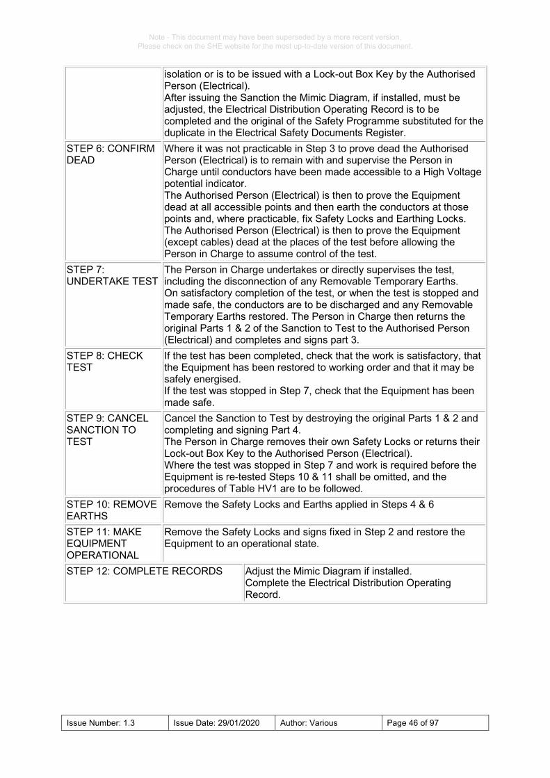
STEP 5: ISSUE SANCTION TO TEST
The prospective Person in Charge is to be shown the electrical diagram on the Safety Programme and the safety arrangements at all the points of isolation and at the places of the test. If a High Voltage Enclosure is to be set up, fix High Voltage Enclosure Signs and barriers. The Person in Charge is to fit their own Safety Locks at all points of
Note - This document may have been superseded by a more recent version. Please check on the SHE website for the most up-to-date version of this document.
Issue Number: 1.3 Issue Date: 29/01/2020 Author: Various Page 46 of 97
isolation or is to be issued with a Lock-out Box Key by the Authorised Person (Electrical). After issuing the Sanction the Mimic Diagram, if installed, must be adjusted, the Electrical Distribution Operating Record is to be completed and the original of the Safety Programme substituted for the duplicate in the Electrical Safety Documents Register.
STEP 6: CONFIRM DEAD
Where it was not practicable in Step 3 to prove dead the Authorised Person (Electrical) is to remain with and supervise the Person in Charge until conductors have been made accessible to a High Voltage potential indicator. The Authorised Person (Electrical) is then to prove the Equipment dead at all accessible points and then earth the conductors at those points and, where practicable, fix Safety Locks and Earthing Locks. The Authorised Person (Electrical) is then to prove the Equipment (except cables) dead at the places of the test before allowing the Person in Charge to assume control of the test.
STEP 7: UNDERTAKE TEST
The Person in Charge undertakes or directly supervises the test, including the disconnection of any Removable Temporary Earths. On satisfactory completion of the test, or when the test is stopped and made safe, the conductors are to be discharged and any Removable Temporary Earths restored. The Person in Charge then returns the original Parts 1 & 2 of the Sanction to Test to the Authorised Person (Electrical) and completes and signs part 3.
STEP 8: CHECK TEST
If the test has been completed, check that the work is satisfactory, that the Equipment has been restored to working order and that it may be safely energised. If the test was stopped in Step 7, check that the Equipment has been made safe.
STEP 9: CANCEL SANCTION TO TEST
Cancel the Sanction to Test by destroying the original Parts 1 & 2 and completing and signing Part 4. The Person in Charge removes their own Safety Locks or returns their Lock-out Box Key to the Authorised Person (Electrical). Where the test was stopped in Step 7 and work is required before the Equipment is re-tested Steps 10 & 11 shall be omitted, and the procedures of Table HV1 are to be followed.
STEP 10: REMOVE EARTHS
Remove the Safety Locks and Earths applied in Steps 4 & 6
STEP 11: MAKE EQUIPMENT OPERATIONAL
Remove the Safety Locks and signs fixed in Step 2 and restore the Equipment to an operational state.
STEP 12: COMPLETE RECORDS Adjust the Mimic Diagram if installed. Complete the Electrical Distribution Operating Record.

Note - This document may have been superseded by a more recent version. Please check on the SHE website for the most up-to-date version of this document.
Issue Number: 1.3 Issue Date: 29/01/2020 Author: Various Page 47 of 97
B4 ENVIRONMENTAL HAZARDS General B4.1 Electrical equipment may be located where additional non-electrical environmental
hazards may be present. All electrical equipment must be suitable for operation within the environment in which it is installed and operated. Examples of environmental hazards are dangerous substances (SF6 – HV dielectric insulator and Asbestos – Arc suppression / electrical insulators), explosive atmospheres, electromagnetic radiation, ionising radiation, strong magnetic fields, oxygen-depletion, laser light and confined spaces. All environmental hazards should be considered. The list provided is for reference and is not conclusive.
B4.2 Where environmental hazards are present reference must be made to: • Relevant Safety Legislation and Regulations; • Relevant SHE codes; • Local Operating Instructions; • Local Rules; and • Manufacturer’s Instructions.
B4.3 Advice should be sought from SHE Group, local Health & Safety Officers,
experimental facility operations managers, relevant Authorising Engineers (Electrical).
B4.4 When working on or testing high or low voltage electrical equipment located within an area containing non-electrical environmental hazards the Authorised Person (Electrical) and / or Nominated Person must comply with the relevant sections of other SHE Codes or Local Rules.
Special precautions for non-electrical environmental hazards
B4.5 The Authorised Person (Electrical) or Nominated Person is to co-ordinate all work
on and testing of Electrical Equipment in co-operation with the person responsible for the Hazardous Area.
B4.6 All persons required to work on or test equipment in a Hazardous Area are to be familiar with, and comply with this and relevant SHE Codes and any instructions issued by the person responsible for the Hazardous Area. If any doubt arises as to the interpretation of such instructions, written clarification from the person responsible for the Hazardous Area is to be obtained before any work or test proceeds.
B4.7 Wherever reasonably practicable, the working place is to be rendered non-hazardous for the duration of the work or test. However, the provisions of this section apply even if the working place has been rendered non-hazardous for the duration of the work or test.
B4.8 Any work or test shall cease immediately on request from the person responsible for the Hazardous Area. The Person in Charge is to report such cessation of work or test to the Authorised Person (Electrical), who is to take appropriate action.
B4.9 All tools, test equipment, and materials must be risk assessed to verify their suitability for use in the Hazardous Area and shall comply with any instructions issued by the person responsible for the Hazardous Area.
B4.10 When using test equipment within a potentially explosive environment additional precautions may be required to prevent currents being generated in other

Note - This document may have been superseded by a more recent version. Please check on the SHE website for the most up-to-date version of this document.
Issue Number: 1.3 Issue Date: 29/01/2020 Author: Various Page 48 of 97
conductors. These currents could spread to other areas and introduce the possibility of sparking. See SHE Code 20 Controlling explosive and flammable gases and dusts.
B4.11 Before commencing any testing, in particular high current continuity tests, prospective short circuit current tests, or high voltage tests the environmental hazards for the Area must be considered.
B4.12 Before a Permit to Work or Sanction to Test is cancelled, the Person in Charge and the Authorised Person (Electrical) are to be satisfied with the integrity of all equipment that may have been affected by the work or test.
B4.13 Before equipment in a Hazardous Area is energised or restored to an operational state, the Authorised Person (Electrical) must obtain permission from the person responsible for the Hazardous Area.
B5 DISPLAY OF SAFETY SIGNS AND POSTERS General B5.1 The design and colours of Warning signs and Caution Notices shall conform to with
BS 5499/EN 7010. See examples of Temporary Warning Signs, Caution Notices, Display of Information and Permanent Safety Signs in Appendix F.
Display of Temporary Warning Signs and Caution Notices B5.2 Authorised Persons (Electrical) and Nominated Persons shall ensure signs and
notices are available when required. Caution Notices will bear the Authorised Persons (Electrical) or Nominated Persons name and the date of when the Notice was displayed.
B5.3 Caution Notices are to be fixed at the points of isolation and prominently displayed before the start and for the duration of work or testing, and before the issue and for the duration of any Permit to Work or Sanction to Test.
B5.4 High Voltage Enclosure Signs are to be prominently displayed so that they are visible from every angle of approach to a High Voltage Enclosure, before the issue and for the duration of a Sanction to Test.
B5.5 Warning Signs are to be prominently displayed, on any equipment which remains live and is adjacent to the Equipment to be worked on or tested, before the start and for the duration of work or testing and before the issue and for the duration of any Permit to Work or a Sanction to Test.
B5.6 Where work or testing is to be undertaken on any part of a multi-cubicle switchboard, Warning Signs shall be prominently displayed on the cubicles or compartments adjacent to the part being worked on or tested. If the board has rear access Electrical Equipment Warning Signs shall similarly be displayed at both the front and rear of the board. In identifying parts at the rear of the board, reliance is not to be placed upon the switchboard labelling.
B5.7 Before a Permit to Work or a Sanction to Test is issued the Authorised Person (Electrical) is required to have identified the equipment upon which the work or test is to be undertaken. If the work or test involves, or may involve, obtaining access to items of Equipment over which confusion could occur, the Authorised Person (Electrical) is to identify such items to the prospective Person in Charge and apply temporary marking to them.
B5.8 Temporary Safety Signs and Notices are to be suspended from non-conducting cords.

Note - This document may have been superseded by a more recent version. Please check on the SHE website for the most up-to-date version of this document.
Issue Number: 1.3 Issue Date: 29/01/2020 Author: Various Page 49 of 97
Display of Permanent Safety Signs B5.9 Signage design should be approved by the Authorising Engineer (Electrical). B5.10 Permanent Safety Signs are to be securely and permanently fixed. B5.11 Signs shall be manufactured from non-metallic weather resistant material. B5.12 Non-corrosive materials are to be used when fixing Permanent Safety Signs. B5.13 A Danger Sign and a Notice identifying the installation are to be displayed in a
prominent position outside every substation. A Notice identifying the installation is to include a contact number in case of emergency or access.
B5.14 A Main Intake Switch Sign is to be displayed on all Low Voltage main intake switches, except for domestic consumer units.
B5.15 A Multiple Supplies Sign is to be displayed on all Low Voltage switchboards and Equipment having two or more sources of supply.
B5.16 A Remotely/ Automatically Controlled Generating Set Sign is to be displayed on or adjacent to all remotely or automatically controlled generating sets.
B5.17 A Remotely/Automatically Controlled Machine Sign is to be displayed on or adjacent to all remotely or automatically controlled machines, except for small sealed refrigerator motors, in-line circulating pumps and other such domestic items.
B5.18 A Danger High Voltage/First Aid for Electrical Shock Sign is to be displayed in all High Voltage switch rooms.
B5.19 A First Aid for Electric Shock Sign is to be displayed in all Low Voltage switch rooms and any other area deemed appropriate by the Authorising Engineer (Electrical).
B5.20 A Danger Live Bus-Bars Sign is to be displayed on switchgear and equipment covers that when removed expose live un-insulated bus-bars.
B5.21 An Uninterruptible Power Supply (UPS) Danger sign is to be displayed on, or adjacent to all circuits and equipment connected to an uninterruptible power supply system.
Display of Information B5.22 The Authorising Engineer (Electrical) is to carry out an assessment to determine the
requirement and location for the display of information in connection with this SHE Code, and Health and Safety matters. Information is to be displayed permanently in a suitable and prominent position. The areas to be considered for the display of information in connection with this SHE Code are to include every intake substation, indoor substation, switch rooms, plant rooms and workshops. A record is to be kept of the assessment for audit and review purposes.
B5.23 Information and posters to be displayed may include the following: • ‘The Electricity at Work Regulations’; • ‘Emergency First-Aid’ (including treatment for electric shock); • Any of the Tables from this SHE Code; • Hazard Assessments; • COSHH Assessments (where required); • Drawings; • Emergency Action Sign; • Other relevant information pertaining to equipment housed in the area (i.e.
Emergency Procedures for hand-winding lifts).

Note - This document may have been superseded by a more recent version. Please check on the SHE website for the most up-to-date version of this document.
Issue Number: 1.3 Issue Date: 29/01/2020 Author: Various Page 50 of 97
B6 ACCOMPANYING SAFETY PERSON B6.1 An Accompanying Safety Person shall be in attendance of electrical work where the
Authorised Person (Electrical) considers that it is necessary, and in the following specific circumstances: • Where working or testing in accordance with Tables LV1, LV2, HV1 or HV2 is to
be undertaken, whilst the equipment is being proved dead; • Where working or testing in accordance with Tables LV1, LV2, HV1 or HV2 is to
be undertaken, whilst the equipment is being earthed, other than by means of a switch or circuit breaker;
• Where working or testing in accordance with Table LV3 is to be undertaken on equipment for which the means of isolation is not positively identified, an Accompanying Safety Person is to be in attendance until the equipment has been isolated and proved dead;
• Where working or testing in accordance with Tables LV1, LV2, HV1 or HV2 is being undertaken on Equipment which cannot be proved dead until after the Permit to Work or Sanction to Test has been issued the Accompanying Safety Person is to be in attendance until the Equipment has been proved dead;
• Whilst work is being undertaken near live high voltage equipment in a high voltage enclosure;
• Whilst a high voltage potential indicator is in use; • Whilst voltage and phasing tests are being undertaken at high voltage; • Whilst tests are being undertaken using high voltage test equipment. • Whilst inspection, fault finding or testing is being undertaken on live Low Voltage
Equipment other than work covered by clause B11.3 to B11.5; • Whilst work is being undertaken on live Low Voltage Equipment that does not
have a level of protection of IP2X or better; • Whilst the Authorised Person (Electrical) or a nominated Contractor appointed by
the Authorised Person (Electrical) is spiking a cable; B7 LOCKING OF SWITCHGEAR AND SWITCHROOMS
B7.1 Where it is necessary to prevent danger or, where appropriate, injury, or prevent
unauthorised operation, equipment cubicles and operating mechanisms are to be locked when the Equipment is unattended.
B7.2 Any entrance to a HV or LV room or enclosure containing a main intake switchboard, central battery system, permanently connected Uninterruptible Power Supply equipment, a generating set or HV equipment is to be closed and securely locked when the equipment is unattended.
B8 SAFETY PROGRAMMES General B8.1 Prior to the issue of any Permit to Work or a Sanction to Test, a Safety Programme
detailing the intended sequence of operations to be performed to make the Equipment safe for the execution of the work or test, is to be prepared.
B8.2 The Authorising Engineer can approve Safety Programme exemptions for Tables LV1 and LV2, provided that a suitable risk assessment has been completed and the details of the exemptions are included on the Authorised Person’s letter of appointment.

Note - This document may have been superseded by a more recent version. Please check on the SHE website for the most up-to-date version of this document.
Issue Number: 1.3 Issue Date: 29/01/2020 Author: Various Page 51 of 97
B8.3 A Safety Programme form shall have an original and a duplicate of each page, and each sheet of a Programme shall bear the same pre-printed serial number. Sets of numbered forms shall be used in sequence.
B8.4 Computer based software (PCMD) can be used to generate an electrical diagram and sequence of switching operation (Switching Schedule).
Contents of Safety Programmes B8.5 The Safety Programme is to be completed in duplicate by the Authorised Person
(Electrical) who is responsible for issuing the Permit to Work or Sanction to Test, and is to indicate: • The purpose of the proposed work or test; • The equipment for which the proposed sequences of operations are intended to
make safe to work on or test; • The location of the equipment; • Details of other safety procedures or documents that relate to the proposed work
or test; • Details of the work or test to be done; • The date on which countersigned programme is required to commence. • Special instructions or safety measures to be included on the Permit to Work or
Sanction to Test; • An electrical diagram of isolating and earthing arrangements; and • The sequence of operations to be undertaken prior to issuing the Permit or
Sanction including: o The location, including any name and identification code, at which each
operation is to be performed; o The identity of each item of switchgear to be operated, including generic
type, manufacturer’s name and manufacturer’s type or reference; o The operation to be performed; o The reason for the operation; o Any items required (for example keys, locks, Protective Equipment); o The requirement for an Accompanying Safety Person for a specific
operation; o The name of the originating Authorised Person (Electrical); and o The name of the countersigning Authorised Person (Electrical).
B8.5 Page one of the original completed Safety Programme is to be signed by the Authorised Person (Electrical) and countersigned by another Authorised Person (Electrical) or Authorising Engineer (Electrical) who has knowledge of the system or installation. The countersigning Authorised Person (Electrical) need not be appointed for the particular equipment, installation or system.
B8.6 The originals of all subsequent Safety Programme and any additional pages should be initialled by the originating and countersigning Authorised Persons (Electrical).
Implementing Safety Programmes B8.7 Before commencing the sequence of operations detailed on the Safety Programme,
the Authorised Person (Electrical) is to confirm that the person responsible for the area and / or equipment has given permission for the intended work or test.
B8.8 Before commencing the sequence of operations the duplicate Safety Programme is to be retained by the Authorising Engineer (Electrical).
B8.9 The Authorised Person (Electrical) is to note on the original Safety Programme the date and time of each operation.

Note - This document may have been superseded by a more recent version. Please check on the SHE website for the most up-to-date version of this document.
Issue Number: 1.3 Issue Date: 29/01/2020 Author: Various Page 52 of 97
B8.10 The Authorised Person (Electrical) is to use the electrical diagram to show the Person in Charge the safety arrangements at the points of isolation and at the places of the work or test.
Completion of Safety Programmes B8.11 On completion of the Safety Programme, the date and time of each switching
operation is to be entered in the Electrical Distribution Operating Record. The original Safety Programme shall be stored in a secure location for three years after the dates on which they were implemented and the duplicate destroyed.
B9 PERMIT TO WORK General B9.1 A Permit to Work must be obtained before any person is allowed to work on:
• bus-bars, switchgear, or isolators located in Low Voltage switch rooms; • incoming Low Voltage switch frames and interconnecting cable networks; • any other high fault capacity equipment not necessarily part of the distribution
network; • street lighting circuits; • where the Authorised Person (Electrical) or Nominated Person considers that it
is necessary after performing a risk assessment; and • all High Voltage equipment.
B9.2 A Permit to Work is to be issued by the Authorised Person (Electrical) to the Person in Charge before any work on defined items of Equipment is commenced. The items of Equipment requiring a Permit are defined in Tables LV1 and HV1.
B9.3 The Permit to Work form shall have an original and duplicate page(s) and bear the same pre-printed serial number and sets of numbered forms organised to be used in sequence.
B9.4 Unless clause B9.5 applies, a Permit to Work is not to be issued for any item of equipment for which an existing Permit to Work, a Sanction to Test or a Sanction for Work on or near Live Electrical Equipment, remains valid, nor for equipment which is within an area for which an Authority for Access exists unless a Risk Assessment indicates that it is safe to do so.
B9.5 More than one Permit to Work may be issued for one item of equipment provided that: • A Risk Assessment indicates that it is safe to do so; • One Safety Programme is prepared which applies to all of the permits; • All the Permits are prepared before any one is issued; • All the permits are issued at or about the same time; • All the Persons in Charge are told of the existence of the other Permits, which
are to be listed in Part 1 of each Permit; and • Multiple locking devices are used, the devices having sufficient capacity to
accommodate the Safety Locks required for all the Permits. B9.6 Permits to Work are to be offered only to Authorised Persons (Electrical) or
Nominated Persons who are in possession of a current letter of appointment appropriate to the equipment to be worked on.
B9.7 On accepting a Permit to Work, the Authorised or Nominated Person becomes the Person in Charge.

Note - This document may have been superseded by a more recent version. Please check on the SHE website for the most up-to-date version of this document.
Issue Number: 1.3 Issue Date: 29/01/2020 Author: Various Page 53 of 97
B9.8 Authorised Persons (Electrical) personally undertaking tasks requiring a Permit to Work must not issue a Permit to themselves. The Authorising Engineer (Electrical) or another Authorised Person (Electrical) with adequate knowledge of the system or systems to be worked on must issue the Permit.
Issue and Acceptance of Permits to Work B9.9 A Permit to Work is, where practicable, to be issued at the place where the work is to
be undertaken. The issue and cancellation of every Permit is to be recorded, for example in the Electrical Distribution Operating Record.
B9.10 Before carrying out any isolation the Authorised Person (Electrical) is to confirm that permission for the intended work has been obtained from the person responsible for the area affected by the intended work.
B9.11 Prior to issuing the Permit to Work the Authorised Person (Electrical) shall: • Positively identify to the Person in Charge the equipment upon which the work is
to be undertaken; • Explain in detail to the Person in Charge the exact extent of the work to be
undertaken; • Draw the attention of the Person in Charge to any special instructions,
environmental hazards and safety measures noted on the Permit; • Show the Person in Charge the electrical diagram on the Safety Programme,
and the safety arrangements at the points of isolation and the places of work; • Unless the sub-clauses below apply, demonstrate to the satisfaction of the
Person in Charge that the Equipment is dead and safe to work on; • For Low Voltage Equipment where it is not practicable to prove equipment dead
prior to issuing the Permit to Work, one of the following sub-clauses shall apply; o the Authorised Person (Electrical) is to instruct the Person in Charge, using
appropriate tools, and Protective Equipment where necessary, to prove the equipment dead as soon as conductors have been made accessible to a suitable voltage test indicator; or
o the Authorised Person (Electrical) is to remain with and supervise the Person in Charge until conductors have been made accessible to a suitable voltage test indicator. The Equipment is to be proved dead to the satisfaction of the Authorised Person (Electrical) and the Person in Charge before the work can proceed.
• Where it is not practicable to prove High Voltage equipment dead prior to issuing the Permit, the Authorised Person (Electrical) having issued the Permit is to remain with and supervise the Person in Charge until the conductor have been made accessible to a High Voltage potential indicator. The Authorised Person (Electrical) is then to prove the equipment dead before allowing the Person in Charge to undertake the work described on the Permit.
B9.12 Where keys are issued for an area under the control of the Authorised Person (Electrical), these keys shall be issued daily to the Person in Charge by the Authorised Person (Electrical) and must be returned to the Authorised Person (Electrical) at the end of each working day, or when work is suspended for the day.
Completion of Work and Cancellation of Permit to Work B9.13 After the work is completed or stopped and all persons, instruments and tools are
withdrawn from the place of work, the Person in Charge is to sign off the Clearance section of the Permit to Work and is to return the original to the Authorised Person

Note - This document may have been superseded by a more recent version. Please check on the SHE website for the most up-to-date version of this document.
Issue Number: 1.3 Issue Date: 29/01/2020 Author: Various Page 54 of 97
(Electrical). When work is stopped the Person in Charge shall also confirm that the equipment has been made safe and write the reasons for stopping the work.
B9.14 Where keys are issued to the Person in Charge for an area under the control of the Authorised Person (Electrical), these keys must be returned to the Authorised Person (Electrical) on clearance of the Permit to Work.
B9.15 The Authorised Person (Electrical) is to check that the work has been satisfactorily completed, and that the equipment is safe. The Authorised Person (Electrical) is then to cancel the Permit to Work by destroying the originals and signing the Cancellation section of the Permit to Work. Single copies of all the pages of the cancelled Permit are to be retained for three years after their dates of cancellation.
B9.16 If the Authorised Person (Electrical) decides, or advised by the person responsible for the Area, that it is necessary to stop the work, the Permit to Work is to be withdrawn and cancelled. The reasons for withdrawal and actions taken are to be noted in the Clearance section of the Permit and in the Electrical Distribution Operating Record.
B9.17 If the Person in Charge loses any part of the original Permit to Work the loss is to be recorded by the Authorised Person (Electrical) and countersigned by the Person in charge. The loss is to be reported to the Authorising Engineer (Electrical).
B10 SANCTION TO TEST General B10.1 A Sanction to Test is to be issued by the Authorised Person (Electrical) to a Person
in Charge before the commencement of:- • any testing of Equipment at High Voltage, or • any testing on Equipment defined by Tables LV2 or HV2 of this SHE Code.
B10.2 A Sanction to Test form shall have an original page and a duplicate page. Each page of a Sanction shall bear the same pre-printed serial number and sets of numbered forms shall be used in sequence.
B10.3 When not in use the Sanction to Test forms are to be kept in a secure location. B10.4 A Sanction to Test is not to be issued for any item of Equipment for which an existing
Sanction to Test, a Permit to Work, or a Permit for Work on or near Live Electrical Equipment, remains valid, nor for Equipment which is within an area for which an Authority for Access exists.
B10.5 Sanctions to Test are to be offered only to Authorised Persons (Electrical) or Nominated Persons who are in possession of a current letter of Appointment appropriate to the Equipment to be tested.
B10.6 On accepting a Sanction to Test, the Authorised or Nominated Person becomes the Person in Charge.
B10.7 Authorised Persons (Electrical) personally undertaking tasks requiring a Sanction to Test must not issue a Sanction to themselves. The Authorising Engineer (Electrical) or another Authorised Person (Electrical) with adequate knowledge of the system or systems to be tested must issue the Sanction.
Issue and Acceptance of Sanction to Test B10.11 A Sanction to Test is, where practicable, to be issued at the place where the testing
is to be undertaken. The issue and cancellation of a Sanction is to be recorded in the Electrical Distribution Operating Record.
B10.12 Before issuing a Sanction to Test, the Authorised Person (Electrical) is to: - • Confirm that permission for the intended test has been obtained from the
person responsible for the area affected by the intended test, and

Note - This document may have been superseded by a more recent version. Please check on the SHE website for the most up-to-date version of this document.
Issue Number: 1.3 Issue Date: 29/01/2020 Author: Various Page 55 of 97
• Positively identify to the Person in Charge the Equipment upon which testing is to be undertaken.
B10.13 Prior to offering a Sanction to Test to the Person in Charge the Authorised (Electrical) is to: • Explain in detail to the Person in Charge the exact extent of the testing to be
undertaken. • Draw the attention of the Person in Charge to any special instructions or
safety measures. • Show the Person in Charge the Equipment on which the tests are to be done. • Show the Person in Charge the electrical diagram on the Safety Programme,
and the safety arrangements at the points of isolation and the places of test, and at other places affected by the test.
• Unless sub-clauses B10.13 apply, demonstrate to the satisfaction of the Person in Charge that the Equipment is dead and safe to test.
• For Low Voltage Equipment where it is not practicable to prove Equipment dead prior to issuing the Permit to Work, one of the following sub-clauses shall apply. o the Authorised Person (Electrical) is to instruct the Person in Charge,
using appropriate tools, and Protective Equipment where necessary, to prove the Equipment dead as soon as conductors have been made accessible to a suitable voltage Test Indicator, or
o the Authorised Person (Electrical) is to remain with and supervise the Person in Charge until conductors have been made accessible to a suitable voltage Test Indicator. The Equipment is to be proved dead to the satisfaction of the Authorised Person (Electrical) and the Person in Charge before the tests can proceed.
• Exceptionally, for High Voltage Equipment, where it is not practicable to prove Equipment dead prior to issuing the Sanction the Authorised Person (Electrical) having issued the Sanction is to remain with and supervise the Person in Charge until conductors have been made accessible to a High Voltage potential indicator. The Authorised Person (Electrical) is then to prove the Equipment dead before allowing the Person in Charge to undertake the tests described on the Sanction.
B10.14 Prior to accepting the Sanction to Test, the Person in Charge, having understood the tests to be carried out, and being prepared to undertake them, is to sign any special instructions or safety measures. The Authorised Person (Electrical) is to retain the duplicate pages and temporarily keep them with the Electrical Distribution Operating Record.
B10.15 After signing to accept the Sanction to Test the Authorised or Nominated Person becomes the Person in Charge and is responsible for personally supervising or undertaking the defined tests. Wherever practicable the Person in Charge is to display the Sanction to Test close to the point of test. The Person in Charge is not to leave the place where the testing is being carried out, or to undertake any other work or tests while the defined tests are in progress. During any temporary absence of the Person in Charge from the place where the testing is being carried out, the tests are to be suspended, and adequate safety precautions taken until testing is resumed on the return of the Person in Charge.
B10.16 Where keys are issued for an area under the control of the Authorised Person (Electrical), these keys shall be issued daily to the Person in Charge by the Authorised Person (Electrical) and must be returned to the Authorised Person (Electrical) at the end of each working day, or when work is suspended for the day.

Note - This document may have been superseded by a more recent version. Please check on the SHE website for the most up-to-date version of this document.
Issue Number: 1.3 Issue Date: 29/01/2020 Author: Various Page 56 of 97
Completion of Tests and Cancellation of Sanction to Test B10.17 After the testing is completed or stopped and all persons, instruments and tools are
withdrawn from the place where testing was undertaken, the Person in Charge is to complete and sign off the clearance section of the Sanction to Test and return the original to the Authorised Person (Electrical).
B10.18 Where keys are issued to the Person in Charge for an area under the control of the Authorised Person (Electrical), these keys must be returned to the Authorised Person (Electrical) on clearance of the Sanction to Test.
B10.19 The Authorised Person (Electrical) is to check that the tests have been satisfactorily completed, and that the equipment is safe. The Authorised Person (Electrical) is then to cancel the Sanction to Test by destroying the originals and signing off the cancellation section of the Sanction. Hard copies of all the pages of the cancelled Sanction are to be retained for three years after their date of cancellation.
B10.20 If the Authorised Person (Electrical) decides, or is advised by the person responsible for the Area, that it is necessary to stop the testing, the Sanction to Test is to be withdrawn and cancelled. The reasons for withdrawal and actions taken are to be noted in the clearance section of the Permit and in the Electrical Distribution Operating Record.
B10.21 If the Person in Charge has lost the original copy of the Sanction to Test, the loss is to be recorded by the Authorised Person (Electrical) in the cancellation section, and in the Electrical Distribution Operating Record. The Person in Charge is to countersign the cancellation section to confirm the loss of the original Sanction. The loss is to be reported to the Authorising Engineer (Electrical).
B11 WORK ON OR NEAR LIVE ELECTRICAL EQUIPMENT B11.1 No person shall be engaged in any low voltage work activity on or near any live
conductor, or near live high voltage conductors in a HV enclosure (other than one suitably covered with insulating material so as to prevent danger) that danger may arise unless: • it is unreasonable in all the circumstances for the conductors to be dead, and it
is reasonable in all circumstances for the person to be at work on or near the conductor while it is live, and suitable precautions (including where necessary the provision of suitable Protective Equipment) are taken to prevent injury; or
• the work is in accordance with clause B11.3 to B11.5. B11.2 The Authorised Engineer (Electrical) is to ensure that the Person in Charge has;
• specified the safety precautions necessary to prevent injury to persons and damage to equipment; and monitored their implementation; and retained copies of the Sanction (if applicable), method statement and risk assessments.
B11.3 Local Rules specific to the activity or a Sanction for Work on or near Live Electrical Equipment is not required if equipment is operating at Extra Low Voltage and a Risk Assessment indicates that live working presents no dangers.
B11.4 Inspection, fault finding and testing of equipment on systems up to 500V ac rms or dc nominal, may be undertaken, without a Sanction for Work on or near live electrical equipment provided that: • It is unreasonable in all circumstances for the conductors to be dead; and • it is reasonable in all circumstances for the person to be at work on or near the
conductor while it is live; and • all live parts are adequately protected to prevent direct contact (IP2X); and • suitable precautions (including where necessary the provision of suitable
Protective Equipment and Personal Protective Equipment) are taken to prevent injury, and

Note - This document may have been superseded by a more recent version. Please check on the SHE website for the most up-to-date version of this document.
Issue Number: 1.3 Issue Date: 29/01/2020 Author: Various Page 57 of 97
• test equipment and all tools in use shall be suitable, for the use for which they are provided and, maintained in a condition suitable for that use and, properly used; and
• adequate precautions are taken to prevent damage to equipment and accidental contact with dangerous live conductors.
B11.5 Inspection, fault finding, testing and topping-up on battery installations, having a terminal voltage not exceeding 500V may be undertaken without a Sanction for Work on or near Live Electrical Equipment. Provided that: • they are sectionalised in such a way that disconnection and separation is
secure; and • each section of batteries has a terminal voltage not exceeding extra low
voltage. Sanction to Work on or Near Live Electrical Equipment General B11.6 A Sanction for Work on or near Live Electrical Equipment is issued by an
Authorised Person and authorised by an Authorising Engineer before the commencement of any work on or near live electrical Equipment. Unless such Equipment is operating at Extra Low Voltage and the Hazards have been assessed and appropriate control measures implemented, or the conditions of clauses B11.3 and B11.5 are applicable.
B11.7 Sanctions for Work on or near Live Electrical Equipment are to be offered only to an Authorised Person (Electrical) or a Nominated Person appointed for the system or installation to be worked on.
B11.8 A Sanction for Work on or near Live Electrical Equipment shall have an original and duplicate page(s) and bear the same pre-printed serial number and sets of numbered forms organised to be used in sequence.
B11.9 Only one set of Sanction for Work on or near Live Electrical Equipment forms are to be in use at any one time for a given Authorised Engineer’s Area of responsibility.
B11.10 When not in use Sanction for Work on or near Live Electrical Equipment forms are to be kept by the Authorising Engineer (Electrical).
B11.11 A Sanction for Work on or near Live Electrical Equipment is not to be issued for any item of Equipment for which an existing Sanction for Work on or near Live Electrical Equipment, a Sanction to Test, or a Permit to Work, remains valid, nor for Equipment that is within an area for which an Authority for Access exists.
B11.12 On accepting a Sanction for Work on or near Live Electrical Equipment, the Authorised Person (Electrical) or Nominated Person becomes the Person in Charge.
Issue and Acceptance of Sanction for Work on or near Live Electrical Equipment B11.13 A Sanction for Work on or near Live Electrical Equipment shall be signed by the
Authorising Engineer (Electrical) or their nominated representative and states that it is unreasonable for the Equipment to be dead, that it is reasonable for the Person in Charge to Work on or near Live Equipment, that suitable precautions have been specified to prevent injury and gives permission for the specified work to proceed.
B11.14 A Sanction for Work on or near Live Electrical Equipment is to be issued, where practicable, at the place where the work is to be undertaken. The issue and cancellation of a Sanction for Work on or near Live Electrical Equipment is to be recorded in the Electrical Distribution Operating Record. (if relevant to system being worked on).

Note - This document may have been superseded by a more recent version. Please check on the SHE website for the most up-to-date version of this document.
Issue Number: 1.3 Issue Date: 29/01/2020 Author: Various Page 58 of 97
B11.15 Prior to offering a Sanction for Work on or near Live Electrical Equipment to the Person in Charge, the Authorised Person (Electrical) is to: - • Positively and physically identify to the Person in Charge the Equipment on
which the work is to be undertaken. • Explain to the Person in Charge the safety precautions to be taken. • Instruct the Person in Charge to inspect all Protective Equipment before use.
B11.16 To accept the Sanction for Work on or near Live Electrical Equipment the Person in Charge and Accompanying Safety Person must sign the ‘receipt’ section of the original and duplicate pages of the Sanction. These signatures render the Sanction valid for the defined work, the Person in Charge shall retain the original pages and the Authorised Person (Electrical) shall retain the duplicate pages.
B11.17 After accepting the Sanction for Work on or near Live Electrical Equipment the Person in Charge is responsible for personally undertaking the defined work. The Person in Charge is, therefore, not to leave the place where the work is being carried out, or to undertake any other work or tests while the defined work is in progress. During any temporary absence of the Person in Charge from the place where the work is being carried out, the work is to be suspended and adequate safety precautions taken until work is resumed on the return of the Person in Charge.
B11.18 The Accompanying Safety Person is not to leave the place where the work is being carried out. During any temporary absence of the Accompanying Safety Person from the place where the work is being carried out, the work is to be suspended and adequate safety precautions taken until work is resumed on the return of the Accompanying Safety Person.
Completion of Work and Cancellation of Sanction for Work on or near Live Electrical Equipment B11.19 Having completed the work and having withdrawn all person, instruments and tools
from the place of work, the Person in Charge is to sign the Clearance section of the Sanction, which was retained by the Authorised Person (Electrical) and is to return the original pages to the Authorised Person (Electrical).
B11.20 Where keys are issued to the Person in Charge for an area under the control of the Authorised Person (Electrical), these keys must be returned to the Authorised Person (Electrical) on signing the Clearance section of the Sanction.
B11.21 The Authorised Person (Electrical) is to check that the work has been satisfactorily completed and that the Equipment is safe. The Authorised Person (Electrical) shall then cancel the Sanction by destroying the original pages and signing the Cancellation section of the Sanction. A copy of each page of the cancelled Sanction is to be retained in a secure location for three years after their date of cancellation.
B11.22 If the Authorised Person (Electrical) decides that it is necessary to stop the work, the Sanction for Work on or near Live Electrical Equipment is to be withdrawn and cancelled. The reasons for the withdrawal and the action taken are to be noted in the Cancellation section and in the Electrical Distribution Operating Record.
B11.23 If the Person in Charge has lost the original pages of the Sanction, the loss is to be recorded by the Authorised Person (Electrical) in the Cancellation section and in the Electrical Distribution Operating Record. The Person in Charge is to countersign the cancellation to confirm the loss of the original Sanction. The loss is to be reported to the Authorising Engineer (Electrical).

Note - This document may have been superseded by a more recent version. Please check on the SHE website for the most up-to-date version of this document.
Issue Number: 1.3 Issue Date: 29/01/2020 Author: Various Page 59 of 97
B12 STANDING INSTRUCTIONS AND SPECIFIC WRITTEN INSTRUCTIONS Standing Instruction B12.1 An Authorised Person (Electrical) may issue a Standing Instruction for:
B12.1.1 Defined tasks on a Low Voltage system or installation; B12.1.2 Inspections, fault finding and testing of Equipment on systems up to
500V AC RMS or DC nominal. The issuing of such a Standing Instruction is limited to areas where it has been decided that these activities may be undertaken without Permit to Work on or near Live Electrical Equipment in accordance with Clauses B11.3 to 11.5;
B12.1.3 Defined switching operations in respect of specific items of High Voltage Equipment and Low Voltage distribution Equipment.
B12.2 A Standing Instruction form shall have original and duplicate pages. Each page of a Standing Instruction shall bear the same pre-printed serial number and sets of numbered forms shall be used in sequence.
B12.3 The original and the duplicate Standing Instruction are to be signed by the Authorised Person (Electrical) appointed for the system or installation to which the Instruction applies.
B12.4 A Standing Instruction is to be offered only to a Nominated Person or an Authorised Person (Electrical) who has knowledge of the system or installation.
B12.5 A Standing Instruction for defined tasks as described in Sub-clause B12.1.2 is to include a signed approval from the Authorising Engineer (Electrical) that states it is unreasonable for the Equipment to be dead, that it is reasonable for the Person in Charge to work on or near live Equipment, that suitable precautions have been specified to prevent injury and gives permission for the specified tasks to proceed.
B12.6 The Authorised or Nominated Person is to acknowledge receipt by completing and signing the Standing Instruction; the signature renders the Instruction valid for the defined work and tests. The original of the Instruction is issued to the Authorised or Nominated Person who thereafter becomes the Person in Charge.
B12.7 The issue of a Standing Instruction is to be recorded in the Electrical Distribution Operating Record.
B12.8 The duplicate of the signed Standing Instruction is to be retained from the date of issue until termination.
B12.9 An Authorised Person (Electrical) may, at any time, cancel a Standing Instruction by retrieving the original from the Person in Charge and destroying it. The duplicate of the Standing Instruction is to be overwritten with the word, “CANCELLED” or “EXPIRED”, as appropriate, followed by the date of termination. The duplicate is to be countersigned by each of the Authorised Persons (Electrical) and retained for three years after its date of termination. The Authorising Engineer (Electrical) is to be notified of the cancellation.
B12.10 The cancellation or expiry of a Standing Instruction is to be noted in the Electrical Distribution Operating Record.
B12.11 A Standing Instruction is to be renewed at intervals not exceeding one year and whenever a new Authorised Person (Electrical) is appointed.
Specific Written Instructions B12.12 The Authorised Person (Electrical) may issue a Specific Written Instruction for a
defined switching operation or a sequence of operations in respect of items of High and Low Voltage Equipment.
B12.13 A Specific Written Instruction form shall have the original and duplicate pages. Each page of a Specific Written Instruction shall bear the same pre-printed serial number and sets of numbered forms shall be used in sequence.
Note - This document may have been superseded by a more recent version. Please check on the SHE website for the most up-to-date version of this document.
Issue Number: 1.3 Issue Date: 29/01/2020 Author: Various Page 60 of 97
B12.14 A Specific Written Instruction is to be offered only to a Nominated Person or an Authorised Person (Electrical) who has knowledge of the system or installation.
B12.15 The Person in Charge is to accept the Specific Written Instruction by signing the original and duplicate; the signature renders the Instruction valid for the defined operations. The original of the Instruction is issued to the Person in Charge.
B12.16 The duplicate of the signed Specific Written Instruction is to be retained by the Authorised Person (Electrical) until the operations are completed and the original returned.
B12.17 The issue of a Specific Written Instruction is to be recorded in the Electrical Distribution Operating Record.
B12.18 On completion of the switching operation the Person in Charge is to return the original Instruction to the Authorised Person (Electrical) without any intentional delay. Details of the switching operations carried out are to be entered in the Electrical Distribution Operating Record. The original is to be retained for three years from the date of issue; the duplicate shall then be destroyed.
B13 AUTHORITY FOR ACCESS General B13.1 The Authorised Person (Electrical) may issue an Authority for Access to a person
of any discipline or specialism. The Authority is issued when any work activities, not requiring a Permit to Work, Sanction to Test, a Sanction for Work on or near Live Electrical Equipment, or not covered by a Standing Instruction or Specific Written Instruction are to be undertaken in an area or location which is normally under the control of the Authorised Person (Electrical).
B13.2 An Authority for Access form shall have an original and duplicate page(s) and bear the same pre-printed serial number and sets of numbered forms organised to be used in sequence.
B13.3 Provided that a documented Risk Assessment indicates that it is safe, an Authority for Access may be issued for work activities to be undertaken in an area or location containing an item of Equipment for which a Permit to Work remains valid.
B13.4 An Authority for Access is not to be issued for an area for which a Sanction to Test or a Sanction for Work on or near Live Electrical Equipment remains valid, or where a High Voltage Enclosure has been set up.
B13.5 Whilst the Authority for Access is in force, the Authorised Person (Electrical) is to inspect the area at the end of each working period or day to ensure that: - • any flammable or hazardous materials introduced into the area during the
work activities are removed when the activities cease at the end of each working period or day;
• access to essential electrical equipment is not obstructed; • the area is secure.
Issue and Acceptance of Authority for Access B13.6 An Authority for Access is to be offered to a person of any discipline or specialism
who is competent to personally execute or supervise the work activities. On accepting the Authority, the person becomes the Person in Charge.
B13.7 Authorities for Access are to be issued, where practicable, at the place where the work activities are to be undertaken. The issue and cancellation of every Authority is to be recorded in the Electrical Distribution Operating Record.

Note - This document may have been superseded by a more recent version. Please check on the SHE website for the most up-to-date version of this document.
Issue Number: 1.3 Issue Date: 29/01/2020 Author: Various Page 61 of 97
B13.8 Prior to offering an Authority for Access to the Person in Charge, the Authorised Person (Electrical) is to: -
• confirm with the Person in Charge in detail the exact extent of the work activities to be undertaken, including the scope and limits;
• show the Person in Charge the area in which the work activities are to be done;
• draw the attention of the Person in Charge to any special instructions and safety measures, and indicate the safety measures applied by the Authorised Person (Electrical);
• Identify to the Person in Charge all items of Electrical Equipment in or adjacent to the work activity area.
B13.14 To accept the Authority for Access the Person in Charge is to sign the receipt section of the original and duplicate pages of the Authority. The signature renders the Authority valid for the defined work activities, and the original pages of the Authority are issued to the Person in Charge. The Authorised Person (Electrical) is to retain the duplicate pages in a secure location.
B13.15 The acceptance of an Authority for Access makes the Person in Charge responsible for personally supervising or undertaking the defined work activities. If the Person in Charge needs to leave the place where the work activities are being carried out, or the work needs to be suspended for a short period of time (not through other works being carried out in the area), the Person in Charge is to ensure the area is left in a safe and tidy condition, and that access to the area is secured.
B13.16 Keys shall be issued daily to the Person in Charge by the Authorised Person (Electrical) and must be returned at the end of each working day, or when work is suspended for the day.
Completion of Work and Cancellation of Authority for Access B13.17 Having completed the work activities and having withdrawn all persons, surplus
materials, instruments and tools from the working place, the Person in Charge is to sign the clearance section of the Authority that was retained by the Authorised Person (Electrical), and is to return the original pages to the Authorised Person (Electrical).
B13.18 All keys issued to the Person in Charge for the area under the control of the Authorised Person (Electrical) must be returned to the Authorised Person (Electrical) on signing the clearance.
B13.19 The Authorised Person (Electrical) is to check that the location has been left in a clean and tidy condition and to secure it against unauthorised access. The Authorised Person (Electrical) is then to cancel the Authority for Access by destroying the original pages and signing the cancellation section. A copy of each page of the cancelled Authority is to be retained in a secure location for three years after their dates of cancellation.
B13.20 If the Authorised Person (Electrical) decides that it is necessary to stop the work activities, the Authority is to be withdrawn and cancelled. The reasons for the withdrawal and the actions taken are to be noted in the cancellation section and in the Electrical Distribution Operating Record.
B13.21 If the Person in Charge has lost the original pages of the Authority for Access, the loss is to be recorded by the Authorised Person (Electrical) in the cancellation section, and in the Electrical Distribution Operating Record. The Person in Charge is to countersign the cancellation to confirm the loss of the original Authority. The loss is to be reported to the Authorising Engineer (Electrical).

Note - This document may have been superseded by a more recent version. Please check on the SHE website for the most up-to-date version of this document.
Issue Number: 1.3 Issue Date: 29/01/2020 Author: Various Page 62 of 97
B14 CERTIFICATE OF TRANSFER OF CONTROL General B14.1 Where, under a project or minor works, the responsibility for an area or piece of
apparatus is to be transferred to a Contractor, a uniquely numbered Certificate of Transfer of Control shall be issued. The Transfer of Control shall pass responsibilities for safety and for the issuing of required documentation to the Contractor for the specified area or equipment.
B14.2 Prior to the issue of a Certificate of Transfer of Control the Authorised Person (Electrical) is to ensure that all persons working on the system under the Certificate can demonstrate their competence on the system to be worked on.
B14.3 Where switching is required under the Certificate, or the issuing of Permits, Sanctions, Instructions, Authorities, or other Certificates, the Contractor’s Authorised Person (Electrical) must present a copy of their Authorised Person’s Certificate (Electrical) from a validated training institution to the STFC Authorised Person (Electrical. This certificate must clearly demonstrate training up to, or exceeding the voltage to be worked on, that has been completed within the last 3 years. The Certificate shall be presented a minimum of 14 days prior to the Transfer of Control.
B14.4 Where a Certificate of Transfer of Control is in place for more than 30 days, the Authorised Person (Electrical) who raised the certificate, or their appointed deputy, shall carry out a monthly audit of all documents issued and assess the progression of work and the safety procedures in place.
B14.5 Where the Authorised Person (Electrical) finds deficiencies in the working practices of the Contractor, the Authorised Person (Electrical) shall, depending on the nature or seriousness of non-compliance: • Request any changes to working practice that the Authorised Person (Electrical)
feels appropriate, or • Issue a letter of Improvement to the contractor giving the contractor a limited
period to meet these requirements, also informing the Project Manager of this action, or
• Issues a letter of Improvement to the contractor for immediate action, also informing the Project Manager and the Authorising Engineer (Electrical) of this action, or
• Ensures all work on the electrical system giving rise to concern is suspended until the issue is resolved, informing the Project Manager and Authorising Engineer of this action.
B14.6 The Contractor issued with the Certificate of Transfer of Control must not transfer control and / or responsibility to a sub-contractor without the approval of STFC Authorised Person.
Implementing a Certificate of Transfer of Control B14.7 A Certificate of Transfer of Control is, where practicable, to be issued at the place
covered by the Certificate. The issue and cancellation of every Certificate is to be recorded in the Electrical Distribution Operating Record
B14.8 Before issuing a Certificate of Transfer of Control the Authorised Person (Electrical) is to: - • agree with the Project Manager, where applicable, the content of the
Certificate, including the Conditions of Issue, • confirm that permission for the intended work has been obtained from the
person(s) responsible for the day to day operations of any area(s) affected by the intended work;

Note - This document may have been superseded by a more recent version. Please check on the SHE website for the most up-to-date version of this document.
Issue Number: 1.3 Issue Date: 29/01/2020 Author: Various Page 63 of 97
• positively identify with the Contractor’s representative the area or equipment covered by the certificate, and thereby defining the limits of the certificate;
• ensure no permits, sanctions, instructions, authorities, or other certificates are open for the areas covered by this Certificate.
B14.9 The Authorised Person (Electrical) shall keep the Duplicate (STFC) copy of the certificate and issue the Original (Contractor’s) copy to the Contractor’s representative, ensuring that the Contractor’s representative is fully aware of their duties. The Original (STFC) copy is to be retained until time of cancellation.
Cancellation of a Certificate of Transfer of Control B14.10 Having completed the work, control shall be returned to STFC by cancellation of
the certificate. Before signing acceptance of the return of control, the STFC Authorised Person (Electrical) shall:- • ensure the area or equipment covered by the Certificate has been left in a
safe and orderly condition; • any permits or sanctions raised by the Contractor’s representative have been
closed; • all keys issued under the certificate have been returned.
B14.11 Once the Certificate has been cancelled by both parties, the Contractor’s representative retains their copy (as proof that he is no longer responsible for the area or Equipment) and the Duplicate (STFC) copy is retained by the STFC Authorised Person (Electrical) and kept for three years after the date of cancellation.
B14.12 If the Contractor’s representative has lost their copy of the Certificate, this loss is to be recorded by the STFC Authorised Person (Electrical) at the bottom of the Duplicate (STFC) copy and in the Electrical Distribution Operating Record. The Contractor’s representative is to countersign the comment on the Duplicate (STFC) copy of the Certificate.
B15 CERTIFICATE OF ISOLATION & EARTHING General B15.1 A Certificate of Isolation and Earthing is a formal statement to be completed by an
Authorised Person (Electrical) responsible for one side of a demarcation line on an electrical distribution system. The Certificate is issued to enable work to be undertaken on an electrical system that is controlled by another Authorised Person or Supply Authority. The Certificate of Isolation and Earthing should normally be issued by the controlling authority, unless otherwise requested.
B15.2 A Certificate of Isolation and Earthing shall be used where: • the Authorised Person (Electrical) requires the supply authority to isolate and,
where required, earth the supply to a main intake of a substation. The Certificate of Isolation and Earthing is to be issued by the supply authority.
• When requested by the supply authority to isolate and, where required, earth their supply to the main intake of an STFC substation.
• the Authorised Person (Electrical) is requested to isolate and, where required, earth an electrical supply to another department or consumer.
• the Authorised Person (Electrical) is requested to isolate and, where required, earth an electrical supply to an area where a Certificate of Transfer of Control has been issued to a Contractor.
• a Risk Assessment deems it necessary to isolate and, where required, earth electrical equipment to facilitate work in the vicinity of electrical services.

Note - This document may have been superseded by a more recent version. Please check on the SHE website for the most up-to-date version of this document.
Issue Number: 1.3 Issue Date: 29/01/2020 Author: Various Page 64 of 97
B15.3 When a Certificate of Isolation and Earthing is used solely for isolation with no earth’s being applied, the section referring to the point at which the equipment is earthed shall be completed with the word ‘None.’
Implementation of Certificate of Isolation and Earthing Where a Safety Programme is to be prepared prior to the issue of the Certificate of Isolation and Earthing the Safety Programme number is to be entered onto the Certificate. B15.4 A Certificate of Isolation and Earthing is to be issued to the Authorised Person
(Electrical) responsible for undertaking the Work on the other side of a line of demarcation, detailing the isolation and earthing operations undertaken by the issuing Authorised Person (Electrical).
B15.5 The recipient of the Certificate of Isolation and Earthing is to acknowledge receipt of the Certificate by signing the original and duplicate copy. The signature renders the Certificate valid for the period of the Work. The original of the Certificate is issued to the receiving Authorised Person (Electrical), who thereafter takes responsibility for carrying out the work.
B15.6 The issue or receipt of a Certificate of Isolation and Earthing and details of the Safety Programme associated with the issue of a Certificate of Isolation and Earthing are to be recorded in the Electrical Distribution Operating Record.
B15.7 The duplicate copy of the signed Certificate of Isolation and Earthing is to be retained by the issuing Authorised Person until the work is completed and the original copy returned.
B15.8 Where testing is required on a supply covered by a Certificate of Isolation and Earthing, on a system which has an Earth applied, the Certificate of Isolation and Earthing shall be cancelled prior to the issuing of a Sanction to Test. A new Certificate of Isolation and Earthing shall be raised, if required, after the cancellation of the Sanction.
Completion of Certificate of Isolation and Earthing B15.9 On completion of the Work requiring the Certificate of Isolation and Earthing, or to
allow a Sanction to Test to be raised, the recipient shall: • confirm the cancellation of all associated Permits or Sanctions; • confirm the removal of all persons under the control of the recipient including
associated tools and equipment; • return the original copy of the Certificate to the issuing Authorised Person and
sign the clearance section on the duplicate copy, and the original where required.
B15.10 The Authorised Person is to sign the cancellation section of the Certificate of Isolation and Earthing (both copies where required) and then restore the network as necessary, or as defined in the Safety Programme.
B15.11 Following cancellation the completed certificate shall be retained for three years after the date of cancellation.
B15.12 If the recipient has lost the original Certificate, the loss is to be recorded by the Authorised Person in the Electrical Distribution Operating Record. The recipient is to sign the clearance section of the duplicate and the Authorised Person is to sign the cancellation section and write on the Duplicate that the ‘Original was lost’. The loss is to be reported to the Authorising Engineer.

Note - This document may have been superseded by a more recent version. Please check on the SHE website for the most up-to-date version of this document.
Issue Number: 1.3 Issue Date: 29/01/2020 Author: Various Page 65 of 97
B16 CONNECTION AND DISCONNECTION NOTICES Connection Notice B16.1 Where there is a requirement to ensure all concerned parties are aware that an
electrical supply has been energised, a Connection Notice may be issued. B16.2 The notice shall state clearly and without ambiguity the supply or supplies that have
been energised. B16.3 A Connection Notice shall have up to 4 copies: an original copy to be retained by
the issuing authority and a duplicate copy retained by the Electrical Contractor, a Principal Contractor (where different) and the STFC Project Manager. Each copy shall bear the same pre-printed serial number. Sets of numbered forms shall be used in sequence.
B16.4 The issuing of a Connection Notice shall be carried out before the supply has been energised.
B16.5 The Authorised Person (Electrical) shall also confirm with the Authorising Engineer (Electrical) that the new system can be connected to the existing site system.
B16.6 Implementation of the Connection Notice should be conducted through the following process: • The Authorising Engineer or designated Authorised Person (Electrical) shall
sign the declaration section and provide details of the supply or supplies that are to be energised, along with the date and time the operation takes place.
• The acknowledgement section of the original copy shall be completed by representatives of the Electrical Contractor, the Principal Contractor (where different), and the STFC Project Manager. In so doing the representatives agree to inform all other members of staff, contractors, or sub-contractors under their control who might be affected by the operation(s) detailed in the declaration section.
• The declaration section of the copies must only be completed by a representative of the Contractor or Group associated with that copy.
• The issue of a Connection Notice is to be recorded in the Electrical Distribution Operating Record.
B16.7 Following the issue of a Connection Notice the completed original copy shall be retained in a secure location and kept for three years after the date of issue.
Disconnection Notice B16.8 Where there is a requirement for proof of electrical disconnection, a Disconnection
Notice may be issued. B16.9 The notice shall state clearly and without ambiguity the disconnection(s) carried out. B16.10 A Disconnection Notice shall have an Original copy and a duplicate copy and shall
bear the same pre-printed serial number on each sheet. Sets of numbered forms shall be used in sequence.
B16.11 The issuing of a Disconnection Notice shall be implemented through the following process: • The declaration section shall be completed by an Authorised Person (Electrical)
or a Nominated Person appointed by the Authorised Person (Electrical) for the work, and, where necessary, in possession of a Permit to Work. The Authorised Person (Electrical) or Nominated Person shall ensure the circuit, system, or apparatus is fully disconnected from all sources of supply;
• The approval section of the notice shall be completed by an Authorised Person (Electrical) only when the declaration section has been completed by a Nominated Person, and shall confirm that the disconnection has been checked.
B16.12 The duplicate copy of the Disconnection Notice shall either be:

Note - This document may have been superseded by a more recent version. Please check on the SHE website for the most up-to-date version of this document.
Issue Number: 1.3 Issue Date: 29/01/2020 Author: Various Page 66 of 97
• Issued to the person in charge of the work for which the disconnection is required;
• Posted on the apparatus that has been disconnected. B16.13 Following the issue of a Disconnection Notice the completed STFC Copy shall be
retained in a secure location and kept for three years after the date of issue. B16.14 If the circuit, system or apparatus being disconnected is to be removed from the
electrical distribution network the mimic diagram must be modified to display the current configuration.
B17 OPERATING RECORDS Electrical Distribution Operating Record B17.1 A bound book (not loose leaf), entitled “Electrical Distribution Operating Record”
shall be clearly and indelibly marked with the name of the location and installation to which the records relate, and shall be kept in locations agreed by the Authorising Engineer.
B17.2 The pages of the book are to be divided into columns with the following headings: -
No. DATE TIME LOCATION & IDENTITY OF
SWITCH
EVENT OR OPERATION & REASON
SIGNATURE
B17.3 Entries are to be made in chronological order and shall record: -
• each individual operation of High Voltage switchgear, unless covered collectively by a single entry of a Switching Programme serial number.
• each operation of Low Voltage distribution switchgear down to and including main intake switches, unless covered collectively by a single entry of a Switching Programme serial number;
• adjustment of the Mimic Panel (if provided) to indicate the present state of the system or installation;
• the relinquishing and acceptance of responsibility between Authorised Person (Electrical)s;
• the issue and cancellation of a Permit to Work, a Sanction to Test, Sanction for Work on or near Live Electrical Equipment or an Authority for Access;
• the withdrawal of a Permit to Work, a Sanction to Test, Sanction for Work on or near Live Electrical Equipment or an Authority for Access, the reason and the action taken;
• the loss of a Permit, a Sanction, a Standing Instruction, a Specific Written Instruction, Connection / Disconnection Notice, Certificate of Isolation & Earthing, Transfer of Control or an Authority for Access;
• the issuing of a connection notice; • the receipt and termination of an Operational Restriction; • any inspection and remedial action associated with an Operational Restriction; • operation of Tap Changers.
B17.4 Electrical Distribution Operating Record books are to be retained in a secure location for a period of three years after the date of the last entry.

Note - This document may have been superseded by a more recent version. Please check on the SHE website for the most up-to-date version of this document.
Issue Number: 1.3 Issue Date: 29/01/2020 Author: Various Page 67 of 97
Switchgear Maintenance and Operating Instructions B17.5 One or more ring binder files entitled “Switchgear Maintenance and Operating
Instructions” are to be prepared. The files are to be clearly and indelibly marked with the location and installation to which the records relate, and are to be kept in a location approved by the Authorising Engineer.
B17.6 The ring binder files are to contain: • Manufacturers’ maintenance and operating instructions for each type of High
and Low Voltage distribution switchgear included in the system or installation with test certificates and records;
• Copies of any Operational Restrictions endorsed with their current status, which are applicable to any Equipment included in the system or installation;
• Information on where maintenance records are to be found. Electrical Distribution Record of Information B17.7 A file entitled “Electrical Distribution Record of Information” shall be kept in a
location approved by the Authorising Engineer, which is clearly and indelibly marked with the location and installation to which the records relate.
B17.8 The file is to contain the following information applicable to the site: - • A site location plan; • Electrical distribution single line diagram; • A location plan and layout drawings of the High Voltage Distribution System, of
each substation, of Low Voltage distribution Equipment (up to an including main intake switches), and Low Voltage switchboards as appropriate;
• Detail of the Regional Electricity Company supplies; • Detail of on-site electricity generation; • A schedule of the High Voltage Switchgear, Distribution Transformers and Low
Voltage Switchgear; • Details, line diagrams and layout drawings of Uninterruptible Power Supply
(UPS) Equipment (other than rack mounted UPS’s). • A cable schedule, including as installed cable route plans and drawings; • Details of Electrical Protection, including over current protection grading charts
and voltage referenced grading charts (as applicable); • Information on where system and circuit load monitoring records can be found.
B18 SAFETY LOCKS, EQUIPMENT SAFETY LOCKS AND LOCK-OUT BOXES B18.1 A Safety Lock is a padlock having only one key, which is different from all other
keys in use on the electrical distribution system. Safety Locks shall be indelibly coloured in red or marked in red, and each Safety Lock and its key must be clearly identified. Safety Locks are to be used only in accordance with this SHE Code.
B18.2 Two procedures for Safety Lock systems are permissible B18.2.1 System A and B18.2.2 System B on their own, or as a mixed system, provided the locks are clearly identified. B18.2.1 System A provides all persons with personal locks as follows:
• each Authorised Person (Electrical) will be issued with 10 Safety Locks, which are keyed alike, and have only one key.
• each Nominated Person will be issued with 4 Safety Locks, which are keyed alike, and have only one key.
• If deemed necessary the Authorising Engineer (Electrical) may issue additional locks to an Authorised or Nominated Person;

Note - This document may have been superseded by a more recent version. Please check on the SHE website for the most up-to-date version of this document.
Issue Number: 1.3 Issue Date: 29/01/2020 Author: Various Page 68 of 97
• each Authorised and Nominated Person will also be issued with Safety Signs and Notices for work or testing in accordance with Table LV3 or for defined tasks described on a Standing Instruction. Such Signs and Locks are to be identifiable to the Authorised or Nominated Person;
• each Authorised or Nominated Person is to retain control of the Safety Locks and Keys at all times. The Keys to Safety Locks when in use are to be controlled by their assigned Authorised or Nominated Person and kept in a secure location;
• safety Locks are to be engraved to identify the Nominated Person or Authorised Person (Electrical) to whom they have been issued and each safety lock and its key are to be numbered for ease of identification.
• safety locks can be assigned to main LV and HV switch rooms and used by Authorised Person (Electrical)s in accordance with Tables LV1, LV2, HV1 and HV2. The Caution Notices applied shall identify the Authorised Person (Electrical).
B18.2.2 System B provides for a store of locks issued as follows: • Safety Locks will only be issued if all Risk Assessments and
Standing/Specific Written Instructions are in place; • Safety Locks and keys are to be individually identified. Where
applicable, the lock number shall be printed on the Permit or Sanction;
• A safety lock is a lock with only one key, which is different from all other keys;
• Each Authorised Person (Electrical) or Nominated Person will collect one or more Safety Locks from the Authorised Person (Electrical) who is issuing the Electrical Permit to work when carrying out an isolation;
• Each Authorised Person (Electrical) or Nominated Person shall also collect the required Safety Signs and Notices for the work or testing in accordance with Table LV1, LV2 & LV3 and these Safety Signs shall contain appropriate contact details;
• The Authorised Person (Electrical) who is issuing the Electrical Permit to work shall ensure that the isolation has been safely completed and the required Safety Signs and Notices displayed, before the Permit or Sanction is issued;
• Once the isolation is complete and the permit or sanction issued, the key(s) are to be retained in a Safety lockout box until the work or test is completed;
• The safety lockout box shall then be locked with two padlocks. The key for one padlock shall be kept by the Authorised Person (Electrical) who issued the Electrical Permit to work. The second padlock key shall then be attached to the Permit to Work or Sanction to Test and will be kept by the Authorised Person (Electrical) or Nominated Person in charge of the work;
• The Safety lockout box shall only be unlocked and the keys contained within released when the permit or sanction is cancelled.
• An Authorised Person’s (Electrical) Safety Lock key may be available to other Authorised Persons (Electrical) having an Authorised Person’s (Electrical) letter of Appointment for the specific Equipment. If the isolation is released by another Authorised Person (Electrical), the issuing Authorised Person (Electrical) must be informed as soon as reasonably practicable.

Note - This document may have been superseded by a more recent version. Please check on the SHE website for the most up-to-date version of this document.
Issue Number: 1.3 Issue Date: 29/01/2020 Author: Various Page 69 of 97
B18.3 An Equipment Safety Lock is a lock with only one key, which is different from all other keys in use on the electrical distribution system, used for securing the means of isolation of specific equipment. Equipment Safety Locks are to be used only in accordance with this SHE Code.
B18.4 Equipment Safety Locks are to be identified with specific Equipment or to an area in which they are to be used (such as a specific Substation High Voltage switch room), and shall bear an identification number.
B18.5 Where appropriate, within an area, a number of Equipment Safety Locks may be kept in the local Operational Key Box, but it may not be necessary to hold locks for each piece of Equipment.
B18.6 When a Permit to Work or a Sanction to Test is to be issued all points of isolation must be secured in the off position using two locks, one lock being an Authorised Person’s (Electrical) Safety Lock and the other the Person in Charge’s Safety Lock. They are to be arranged so that both locks must be released before the system can be made operational. When the Permit is issued the Authorised Person (Electrical) and Person in Charge must retain their own Safety Lock keys.
B18.7 On specific equipment an Authorised Person (Electrical) may decide to use Equipment Safety Locks to secure isolation.
B18.8 After the Equipment Safety Locks have been applied, and before the Permit to Work or Sanction to Test is issued, the keys to all the Equipment Safety Locks must be secured in an approved Lock-Out Box.
B18.9 Lock-Out Boxes are to be secured by two Safety Locks, one being the Person in Charge’s Safety Lock, and the other the Authorised Person’s (Electrical) Safety Lock. The locks are to be arranged so that both locks must be released before access is gained to the contents of the Lock-Out Box.
B18.10 When not in use, Equipment Safety Locks and their keys are to be kept in an appropriate key cabinet.
B18.11 During an Emergency or loss of Safety Lock key the removal of the Safety lock can only be approved by the Authorising Engineer or their nominated representative.
B19 KEYS, KEY CABINETS, MIMIC DIAGRAMS AND PADLOCKS TO SECURE
REMOVABLE TEMPORARY EARTHS Keys for Switchgear and Buildings B19.1 The administration and use of suited lock systems in connection with this SHE
Code is to be approved by the Authorising Engineer (Electrical). The Authorised Person (Electrical) must retain control of all keys to suited lock systems installed in connection with this SHE Code and the Authorising Engineer (Electrical) is to audit these control procedures.
B19.2 Keys issued to an Authorising Engineer (Electrical), Authorised Person (Electrical), or Nominated Person on a permanent basis, shall not be loaned or transferred to other persons.
B19.3 If an Authorised Person’s (Electrical) or Nominated Person’s letter expires and is not renewed, or is withdrawn, the Authorising Engineer (Electrical) is to ensure that any keys issued to that person are returned.
B19.4 Where keys to suited locks are issued to persons, other than those covered by Clause B19.2, the specific use and purpose intended for the keys is to be detailed on a Standing Instruction, a Specific Written Instruction, Permit, Sanction, or an Authority for Access issued to that person.
B19.5 Key plates, may be used, and may bear the identification of the substation, building or item of Equipment to which the keys belong, or the purpose for which each key is intended.

Note - This document may have been superseded by a more recent version. Please check on the SHE website for the most up-to-date version of this document.
Issue Number: 1.3 Issue Date: 29/01/2020 Author: Various Page 70 of 97
Key Cabinets B19.6 Key Cabinets are to be installed in appropriate locations in connection with this SHE
Code and clearly marked with a unique identifier. B19.7 The Authorising Engineer (Electrical) shall keep a list of all Key Cabinets installed in
connection with this SHE Code. This list shall include the following:- • Locations of all Key Cabinets and their unique identifiers; • The contents of each Key Cabinet; • The names of each Authorised Person (Electrical) who has access.
B19.8 A copy of this list shall be made available to all Authorised Persons (Electrical). Padlocks to Secure Removable Temporary Earths (Earthing Locks) B19.9 Padlocks (Earthing Locks) used to secure Removable Temporary Earths are to
have only one key which is different from all other keys used on the electrical distribution system. Earthing Locks shall be indelibly coloured in yellow or marked in yellow, and each Earthing Lock and its key must be clearly identified. Earthing Locks are to be used only in accordance with this SHE Code.
B19.10 The keys for locks used by the Authorised Person (Electrical) to secure Removable Temporary Earths are to be issued by the Authorised Person (Electrical) to the Person in Charge, who is to retain control of them for the duration of the test.
B19.11 Earthing Locks and their keys may be held in local Operation Key Cabinets within Substations, but are not specific to one piece of Equipment.
Mimic Diagram B19.12 A Mimic Diagram is to be provided for all High Voltage distribution systems and Low
Voltage distribution systems which include a ring circuit, an automatically started generating set, or a fixed uninterruptible power supply >100kVA.
B19.13 A Mimic Diagram is to show, as a minimum, the HV electricity distribution system and Equipment that is under the control of the Authorised Person, from all sources of supply up to and including Low Voltage Interconnectors.
B19.14 Substations and major Low Voltage intakes are to be appropriately labelled on the Mimic Diagram.
B19.15 The Mimic Diagram must be permanently displayed and accessible to all Authorised Persons. The status of the electricity distribution system and Equipment is to be visible at all times, but the Mimic Diagram is to be lockable to prevent unauthorised adjustment.
B19.16 An electronic Mimic Diagram is acceptable as long as it conforms to clauses B19.12 to B19.14, but consideration should be given to how the diagram might be accessed during a total supply failure. A line diagram of the associated distribution system shall be displayed in all the main LV and HV switch rooms. A hard copy of the Mimic diagram showing the status of the associated distribution system must be clearly displayed when work or test is undertaken.
B20 USE AND PROVISION OF PROTECTIVE, TEST, EARTHING, AND LIFTING
EQUIPMENT Use, Storage, Inspection and Documentation B20.1 Protective Equipment, Test Equipment and earthing Equipment is to be maintained
and stored in accordance with the manufacturer’s or supplier’s instructions, and it is to be inspected by the user on each occasion before use, and is to be properly used.

Note - This document may have been superseded by a more recent version. Please check on the SHE website for the most up-to-date version of this document.
Issue Number: 1.3 Issue Date: 29/01/2020 Author: Various Page 71 of 97
B20.2 The location of Protective Equipment, Test Equipment and portable earthing Equipment is to be prominently displayed adjacent to the Working Key Cabinet.
B20.3 Where Protective Equipment, Test Equipment, and portable earthing Equipment is kept on site for use in connection with this SHE Code, details and copies of the equipment specification, operation, maintenance and where appropriate, calibration, are to be kept in a location approved by the Authorising Engineer.
B20.4 Unless more frequent intervals are specified by the manufacturer or supplier an Authorised Person (Electrical) is to inspect each item of Protective Equipment and portable earthing Equipment, kept on the site, at least once a year and in accordance with the manufacturer’s or supplier’s instructions, to ensure that it is suitable for the use for which it is provided and it is maintained in a condition suitable for that use. Where protective equipment, test equipment and portable earthing equipment is found to be defective or faulty it is to be taken out of use and suitable precautions implemented to prevent further use. The inspecting Authorised Person (Electrical) is to instigate the appropriate remedial or replacement action where necessary. These inspections are to be recorded in the Electrical Distribution Operating Record, as well as in any other maintenance and inspection record system.
B20.5 Where practicable, lifting equipment shall be kept with the switchgear for which it is associated.
B20.6 Reports for each inspection of lifting equipment are to be kept in the Switchgear Maintenance and Operating Instructions ring binder.
B20.7 The Authorising Engineer (Electrical) is to review the records every twelve months to determine that the maintenance and inspection is being carried out for protective equipment, lifting equipment, test equipment and portable earthing equipment kept on site.
Protective Equipment B20.8 Appropriate protective equipment is to be provided and is to be readily available at
all times to those who need it in connection with this SHE Code. Protective equipment is to be used whenever necessary to prevent danger or, where appropriate, injury and as required by this SHE Code.
B20.9 Protective equipment, in normal circumstance is to be provided by the person responsible for the work activities. Protective equipment provided by the Person in Charge may be used if the Authorised Person (Electrical) agrees, and such use is to be recorded.
B20.10 Protective equipment is to be inspected by the Person in Charge for visible defects on each occasion prior to use to ensure that it is suitable for the use for which it is provided, and that it has been maintained in a condition suitable for that use, when properly used. Any suspect item is to be reported to the Authorised Person (Electrical) who is to consider its withdrawal and replacement.
Test Equipment B20.11 The Authorised Person (Electrical) is to arrange for the necessary test equipment to
be available when required in connection with this SHE Code. B20.12 Test equipment is to be, where appropriate, calibrated in accordance with the
manufacturer or supplier’s instructions. B20.13 Test equipment is to be inspected by the user for visible defects on each occasion
prior to use to ensure that it is suitable for the use for which it is provided, and that it has been maintained in a condition suitable for that use, when properly used. Any suspect item is to be reported to the Authorised Person (Electrical) who is to consider its withdrawal and replacement.

Note - This document may have been superseded by a more recent version. Please check on the SHE website for the most up-to-date version of this document.
Issue Number: 1.3 Issue Date: 29/01/2020 Author: Various Page 72 of 97
Earthing Equipment B20.14 Before conductors are earthed a check is to be made to confirm that the earthing
Equipment to be used is of sufficient strength and current-carrying capability to discharge electrical energy to earth without danger or, where appropriate, risk of injury.
B20.15 The appropriate manufacturer’s or supplier’s proprietary earthing Equipment is to be used where it is available; where none is available, purpose made earthing Equipment may be used with the Authorising Engineer’s (Electrical) approval.
B20.16 Portable earthing Equipment is to be inspected by the user before each use to confirm that it is suitable for use for which it is provided, and that it has been maintained in a condition suitable for that use, when properly used. Any suspect item is to be reported to the Authorised Person (Electrical) who is to consider its withdrawal and replacement.
Lifting Equipment B20.17 Registered and inspected lifting equipment associated with the switchgear shall be
used at all times. Where none is available, other means may be used with the Authorising Engineer’s (Electrical) approval, see SHE code 26 Safe use of lifting equipment.
B21 TEMPORARY SUPPLIES, INTERLOCKS, & EMERGENCY SHUTDOWN
CONTROLS Temporary Supplies B21.1 An electrical cable that has been installed for a particular purpose and will be
removed when no longer required for that purpose. B21.2 All Temporary Supplies shall be registered, bearing a registration label at the supply
end of the cable and shall be securely fastened to the cable at a point where it can be readily seen.
B21.3 Before any registered Temporary Supply is put into service a full electrical test as required under a BS7671 installation certificate shall be carried out and the certificate forwarded to the designated Authorised Person (Electrical).
B21.4 All Temporary Supplies shall be inspected every month. This will involve the following work to be carried out: • A visual inspection of the cable throughout its route, ensuring all labels are in
place. Any changes, not previously identified, to the route, fixings, or condition of the cable shall be recorded and a full electrical test and inspection shall be carried out as described in BS7671 for periodic testing;
• An earth-loop impedance test shall be carried out; • Inspection and test results shall be forwarded to the defined Authorised Person
(Electrical) who is to place the documents in the Temporary Supplies Document Folder.
B21.5 If a Temporary Supply has not been inspected or tested for a period greater than 60 days (due to non-compliance of the user to agree an inspection to be carried out as described in Clause B21.4 or where changes have occurred, the Authorised Person (Electrical) should isolate the supply and lock it off until a full test has been carried out on the installation.
B21.6 A Temporary Supply shall have a life span not exceeding 1 year. B21.7 Inspection and test results for a temporary supply are to be kept for 3 months
following its removal.

Note - This document may have been superseded by a more recent version. Please check on the SHE website for the most up-to-date version of this document.
Issue Number: 1.3 Issue Date: 29/01/2020 Author: Various Page 73 of 97
Interlocks B21.8 A register of Interlock Key-Codes is kept by SHE Group who will authorise the use of
such codes, and ensure that no duplicates exist. An electronic list is viewable and editable at https://staff.stfc.ac.uk/she/Pages/Keys.aspx if in doubt consult an Authorised Person or Authorising Engineer.
B21.9 Where Interlocks are used on Distribution Networks, override Maintenance Keys may be available to change the supply configuration without an interruption of supply. Maintenance Keys shall be: • kept in a Key Cabinet remote from the Equipment they control; • issued only by the Authorising Engineer (Electrical) as a requirement under a
Safety Programme; • used only by the Authorising Engineer (Electrical) or an Authorised Person
(Electrical); and • returned to the Key Cabinet as soon as the work is completed. It is the
responsibility of the Authorising Engineer (Electrical) to ensure the Maintenance Key is returned.
B21.10 Where Interlocks are used on Experimental Equipment reference shall also be made to appendix A5.
Emergency Shutdown Facilities B21.11 Where there is an increased danger that an electrical incident or fire may occur,
such as in experimental areas and laboratories, the inclusion of emergency shutdown buttons or break-glass units to interrupt all electrical supplies should be considered.
B21.12 Emergency shutdown control points shall be situated in prominent positions and shall be clearly labelled to indicate what they control. Circuit reference numbers shall also be included.
B21.13 All personnel working in these areas shall be shown where these control points are located and instructed in their operation.
B21.14 The design and positioning of such control points shall include consideration to avoid accidental tripping.
B21.15 Consideration should also be given in the design to the way tripped circuits are reset. Whilst for most applications an automatic reset occurs when the button is released or the glass replaced, other applications may require a more controlled method of reset.
B21.16 Shutdown circuits shall be fully tested annually. For main High Voltage and Low Voltage distribution panels only, however, local procedures, agreed with the Authorising Engineer (Electrical), may be used to prevent a full trip of the breakers.
B22 IDENTIFICATION OF SERVICES AND SPIKING CABLES B22.1 Prior to undertaking electrical work where hidden services may be present, for
example gas, electric and water, undertake a site survey, see SHE Code SC19 Work on buildings, services, premises and infrastructure.
B22.2 Before the conductors of a cable are cut or exposed, the origin, the point of the work and the destination of the cable to be worked on are to be identified with certainty.
B22.3 The identification may be regarded as clear and certain if the cable is visible throughout its length.

Note - This document may have been superseded by a more recent version. Please check on the SHE website for the most up-to-date version of this document.
Issue Number: 1.3 Issue Date: 29/01/2020 Author: Various Page 74 of 97
B22.4 Identifying a cable by passing an electrical signal along it is not by itself a reliable means of identification, since cables running alongside are inductively coupled and may give a false identification.
B22.5 Cables without an earth bonded metallic sheath or armouring are not to be spiked. B22.6 In the absence of clear and certain identification, the cable is to be spiked at the
point of the work and thereafter identified by an appropriate procedure. Before spiking it may be necessary to undertake tests, which are to be repeated after spiking, and the results compared.
B22.7 Cable spiking equipment is available in two forms of operation; hydraulically or by explosive cartridge. The spiking of cables is to be undertaken only by: • An STFC Authorised Person (Electrical) trained in the use of cable spiking
equipment; • An Authorised Person (Electrical) employed directly or indirectly by a
Contractor, trained in the use of cable spiking equipment, and approved by an STFC Authorised Person (Electrical).
• A contractor trained in the use of cable spiking equipment, who has demonstrated sufficient competency, and who is in possession of Specific Written Instruction issued by an STFC Authorised Person (Electrical).
B22.8 Cable locating devices should, as a minimum, be rugged and weatherproof to NEMA 3S, comply with EMC standards, and be produced by BS EN ISO 90001:2008 accredited manufacturers.
B23 OPERATIONAL RESTRICTIONS
This is a written instruction, issued by the Authorising Engineer (Electrical), a supply authority, a manufacturer, or a supplier of Electrical Equipment, modifying or prohibiting the normal operating procedures associated with a particular type of Equipment. General
B23.1 Any Authorising Engineer (Electrical) receiving or discovering an Operational
Restriction without any indication of it having been advised through STFC is to forward a copy, as soon as is practicable, to all other Authorising Engineers (Electrical) within STFC.
B23.2 Any Authorised Person (Electrical) receiving or discovering an Operational Restriction is to advise the Authorising Engineer (Electrical) as soon as is practicable.
B23.3 On receipt of an Operational Restriction, the Authorising Engineer (Electrical) shall:- • Investigate whether or not the Equipment is included in their appointed systems
or installations; • Retained a copy of Operational Restriction in a secure location;
B23.4 Where the Operational Restriction relates to equipment that forms part of the appointed systems or installations, the Authorising Engineer (Electrical) shall ensure: • An Operational Restriction notice is securely fixed to the Equipment warning of
the Restriction and ensure all Authorised Persons (Electrical) are informed of the Notice;
• The withdrawal or revision (if applicable) of any Standing Instructions permitting operation of the Equipment, any revisions must incorporating the Operational Restrictions;
• The Operational Restriction is noted in the Electrical Distribution Operation Record;
• Arrangement of any necessary inspections and remedial work;

Note - This document may have been superseded by a more recent version. Please check on the SHE website for the most up-to-date version of this document.
Issue Number: 1.3 Issue Date: 29/01/2020 Author: Various Page 75 of 97
B23.5 The completion of inspections and remedial work arising from the Operational Restriction is to be noted in the Electrical Distribution Operation Record and reported to the Authorising Engineer (Electrical).
B23.6 The Authorised Person (Electrical) is to ensure that copies of the inspection reports and details of any remedial work undertaken are:- • Retained in a location approved by the Authorising Engineer (Electrical); • Forwarded to the Authorising Engineer (Electrical).
B23.7 The Authorising Engineer (Electrical) is to notify all Authorised Persons (Electrical) of the termination of an Operational Restriction. The termination of an Operational Restriction shall also be noted in the Electrical Distribution Operating Record.
B23.8 On termination: • The copy of the Operational Restriction held by the Authorising Engineer
(Electrical) is to be overwritten with the word “CANCELLED” followed by the date of the cancellation. It should be retained for a period of three years after the date of cancellation;
• The copy in the Switchgear Maintenance and Operating Instructions file is to be overwritten with the word “CANCELLED” followed by the date of cancellation, and retained in the file;
• Any Standing Instructions which incorporate the conditions of the Operational Restriction are to be withdrawn and replaced by new Standing Instructions.
B24 CONSTRUCTION (DESIGN AND MANAGEMENT) REGULATIONS (2007) B24.1 For further information regarding the application of CDM to electrical works, see
STFC Safety Code SC13 and Safety Code SC19 Work on building, premises, services and infrastructure.
B25 THE ACCEPTANCE OF NEW WORKS B25.1 Having visited the site of the new works on main LV or HV Electrical Distribution
Systems, the Authorising Engineer (Electrical) is to be satisfied that: • there is adequate space and suitable access to enable maintenance and
operation to be safely undertaken; • the installation is of an acceptable standard; • the Equipment is suitable for its intended purpose; • compatible design philosophies have been applied to the entire electrical
installation for the new works; • the new works do not compromise the integrity of the existing electrical
installation; and • there is a Health and Safety File holding sufficient information to enable
operation and maintenance to be undertaken safely. B25.2 The Authorising Engineer (Electrical) may accept an installation that does not satisfy
Clause B25.1 subject to the issuing of an Operational Restriction. B25.3 The STFC Authorising Engineer (Electrical) is to nominate Authorised Person(s)
(Electrical) designate for the new systems or installation. The Authorising Engineer (Electrical) is to ensure appropriate familiarisation and on-site training in accordance with Appendix C is given to the Authorised Person(s) (Electrical) designate.
B25.4 Before an installation is connected to the system for the first time:

Note - This document may have been superseded by a more recent version. Please check on the SHE website for the most up-to-date version of this document.
Issue Number: 1.3 Issue Date: 29/01/2020 Author: Various Page 76 of 97
• STFC is to be satisfied that the installation complies with the Electricity at Work Regulations, the Electricity Safety, Quality and Continuity Regulations, and any other appropriate statutory and mandatory regulations;
• all required design, installation, commissioning, and test certificates shall be handed over to STFC;
• check fuse ratings or protection settings to ensure both discrepancy and protection levels are acceptable;
• all necessary signage and labelling must be fitted; • all keys associated with the new works shall be handed over to STFC.
B25.5 Before a formal handover is deemed complete, the Contractor shall ensure the area has been left in an acceptable condition with all waste removed and any ground works made good.