appendix a technology descriptions - srs
TRANSCRIPT

APPENDIX A
TECHNOLOGY DESCRIPTIONS

DOE/EIS-0279March 2000 Technology Descriptions
A-iii
TABLE OF CONTENTS
Section Page
A.1 New Packaging Technologies .......................................................................................... A-1A.1.1 Direct Disposal................................................................................................... A-1A.1.2 Direct Co-Disposal............................................................................................. A-2
A.2 New Processing Technologies.......................................................................................... A-2A.2.1 Melt and Dilute .................................................................................................. A-2A.2.2 Press and Dilute ................................................................................................. A-5A.2.3 Chop and Dilute ................................................................................................. A-6A.2.4 Dissolve and Vitrify............................................................................................ A-7A.2.5 Glass Material Oxidation and Dissolution System ............................................... A-7A.2.6 Plasma Arc Treatment ........................................................................................ A-8A.2.7 Electrometallurgical Treatment ........................................................................... A-10A.2.8 Technologies Not Analyzed ................................................................................ A-12
A.3 Conventional Processing ................................................................................................. A-13References ................................................................................................................................. A-16
List of Figures
Figures Page
A-1 Direct Disposal/Direct Co-Disposal process flow diagram. .............................................. A-3A-2 Melt and Dilute technology process flow diagram. ........................................................... A-4A-3 Press and Dilute process flow diagram. ........................................................................... A-6A-4 Dissolve and Vitrify process flow diagram....................................................................... A-7A-5 Glass Material Oxidation and Dissolution process flow diagram. ..................................... A-9A-6 Plasma Arc Treatment process flow diagram. .................................................................. A-10A-7 Electrometallurgical Treatment process flow diagram. ..................................................... A-12A-8 Conventional Processing flow diagram. ........................................................................... A-15


DOE/EIS-0279March 2000 Technology Descriptions
A-1
APPENDIX A. TECHNOLOGY DESCRIPTIONS
This appendix describes the technology optionsthat the U.S. Department of Energy (DOE) con-sidered for implementing the spent nuclear fuel(SNF) management alternatives. As described inChapter 2, DOE consolidated many of these op-tions and eliminated two from further considera-tion. This appendix addresses each technologyoption. The options are grouped according to thetechnology to which they would apply.
A.1 New Packaging Technologies
A.1.1 DIRECT DISPOSAL
As the first step in the Direct Disposal process,the shipping cask would be received and un-loaded in the Transfer and Storage Facility orTransfer, Storage, and Treatment Facility. Thespent nuclear fuel would be placed in lag storageand the cask would be decontaminated and re-turned for reuse. The fuel would remain in lagstorage until it was ready to be conditioned andrepackaged for road-ready storage.
Conditioning activities prior to repackagingwould include decanning canned fuel, croppingfuel assemblies to eliminate most of the nonfuelstructural components, and limited characteriza-tion. The characterization would involve re-viewing records, weighing and visually inspectingthe fuel, and conducting gamma spectrometryand tests for cladding integrity. In some cases,more complete characterization could be neces-sary and could result in samples being taken foradditional analysis. Failed fuel and other specialcase fuel would be recanned.
The SNF and failed fuel in cans then would beplaced in canisters for road-ready storage. Thefuel could be loaded into the canisters in a varietyof positions, depending on the size of the fuel andits uranium content. For the Direct Disposal op-tion, DOE could use a 24-inch (61-centimeter)diameter canister available in 5-, 10-, or 16-foot(1.5-, 3-, or 4.9-meter) lengths. Metal frames
(called baskets) would be inserted
into the canister to hold the fuel in a fixed posi-tion. For materials test reactor-like fuels(Group B), which make up about 97 percent ofthe volume of the aluminum SNF inventory, eachbasket would hold 16 fuel assemblies; a 10-foot(3-meter) canister could hold four baskets verti-cally stacked. Therefore, one 10-foot (3-meter)long canister would hold up to 64 materials testreactor-like fuel assemblies. The amount of fis-sile mass in the fuel could limit the length of thecanister and decrease the number of fuel assem-blies loaded into each canister. Dry storagespace for about 1,100 24-inch (61-centimeter)diameter canisters would be needed for the DirectDisposal technology.
Before sealing the canisters, the assemblieswould be vacuum-dried to remove free water.Water could contribute to continued corrosion ofthe fuel and to the buildup of hydrogen gas whichcan be generated by radiolytic decomposition ofthe water and by metal corrosion. Group A fu-els, which are uranium or thorium metal, aremore reactive than other fuels and would needmore extensive drying to remove the bound wa-ter. Hot vacuum drying has been effective ineliminating bound water. However, including hotvacuum drying capability in the Transfer andStorage Facility for the small amount of Group Amaterial (approximately 4 cubic yards [3 cubicmeters]) would require a large expenditure thatcould be disproportionate to the benefit.
Depending on the design of the Transfer andStorage Facility, the canisters could be placed instorage singly, in storage overpacks singly or ingroups, or in shipping casks (for storage) singlyor in groups. Regardless of design, the fuelwould be considered road-ready because no fur-ther characterization, conditioning, or other han-dling would be necessary before shipment. Thecanisters could require packaging into shipping
DOE/EIS-0279Technology Descriptions March 2000
A-2
casks, and they could need venting (to relievebuildup of hydrogen) before shipping.
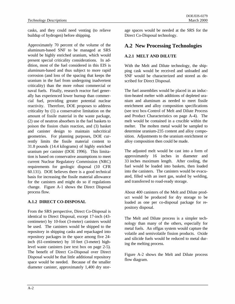
Approximately 70 percent of the volume of thealuminum-based SNF to be managed at SRSwould be highly enriched uranium, which wouldpresent special criticality considerations. In ad-dition, most of the fuel considered in this EIS isaluminum-based and thus subject to more rapidcorrosion (and loss of the spacing that keeps theuranium in the fuel from undergoing inadvertentcriticality) than the more robust commercial ornaval fuels. Finally, research reactor fuel gener-ally has experienced lower burnup than commer-cial fuel, providing greater potential nuclearreactivity. Therefore, DOE proposes to addresscriticality by (1) a conservative limitation on theamount of fissile material in the waste package,(2) use of neutron absorbers in the fuel baskets topoison the fission chain reaction, and (3) basketand canister design to maintain subcriticalgeometries. For planning purposes, DOE cur-rently limits the fissile material content to31.8 pounds (14.4 kilograms) of highly enricheduranium per canister (DOE 1996). This limita-tion is based on conservative assumptions to meetcurrent Nuclear Regulatory Commission (NRC)requirements for geologic disposal (10 CFR60.131). DOE believes there is a good technicalbasis for increasing the fissile material allowancefor the canisters and might do so if regulationschange. Figure A-1 shows the Direct Disposalprocess flow.
A.1.2 DIRECT CO-DISPOSAL
From the SRS perspective, Direct Co-Disposal isidentical to Direct Disposal, except 17-inch (43-centimeter) by 10-foot (3-meter) canisters wouldbe used. The canisters would be shipped to therepository in shipping casks and repackaged intorepository packages in the space among five 24-inch (61-centimeter) by 10 feet (3-meter) high-level waste canisters (see text box on page 2-5).The benefit of Direct Co-Disposal over DirectDisposal would be that little additional repositoryspace would be needed. Because of the smallerdiameter canister, approximately 1,400 dry stor-
age spaces would be needed at the SRS for theDirect Co-Disposal technology.
A.2 New Processing Technologies
A.2.1 MELT AND DILUTE
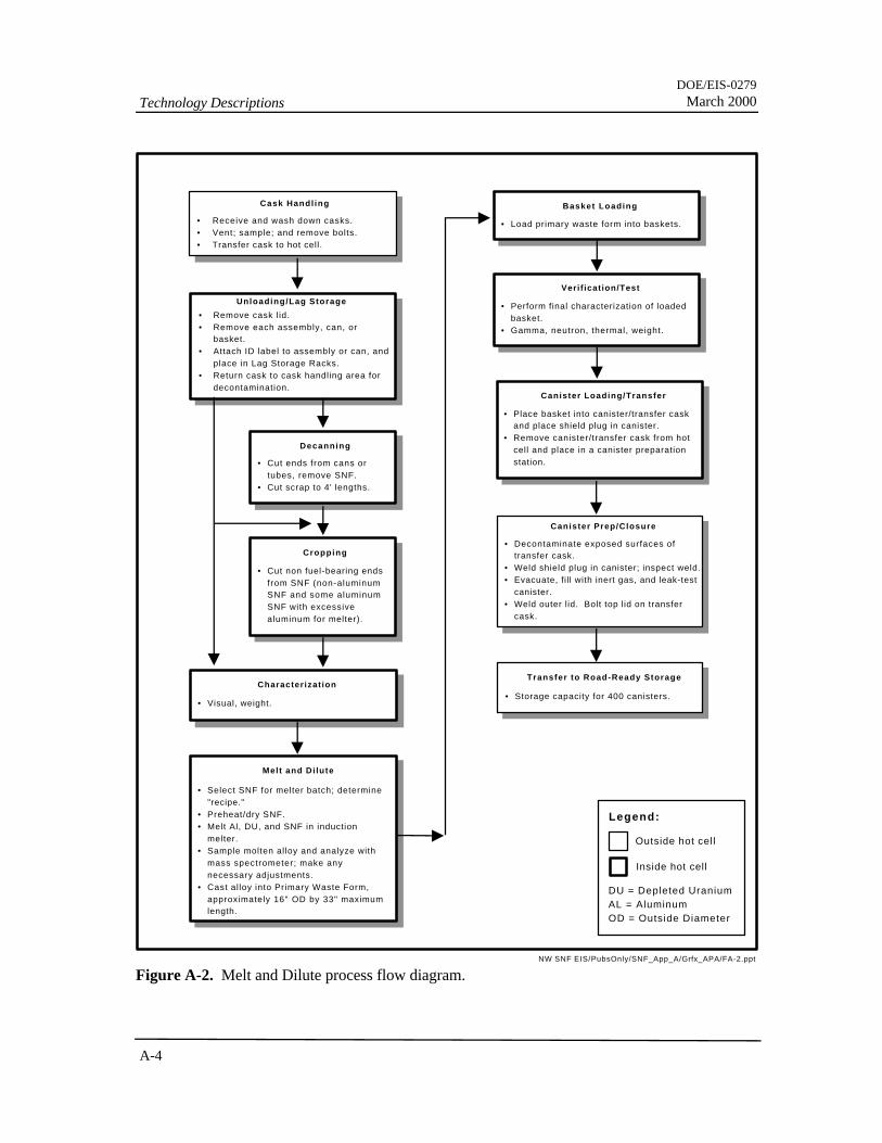
With the Melt and Dilute technology, the ship-ping cask would be received and unloaded andSNF would be characterized and stored as de-scribed for Direct Disposal.
The fuel assemblies would be placed in an induc-tion-heated melter with additions of depleted ura-nium and aluminum as needed to meet fissileenrichment and alloy composition specifications(see text box-Control of Melt and Dilute Processand Product Characteristics on page A-4). Themelt would be contained in a crucible within themelter. The molten metal would be sampled todetermine uranium-235 content and alloy compo-sition. Adjustments to the uranium enrichment oralloy composition then could be made.
The adjusted melt would be cast into a form ofapproximately 16 inches in diameter and33 inches maximum length. After cooling, thefuel would be loaded into baskets, then loadedinto the canisters. The canisters would be evacu-ated, filled with an inert gas, sealed by welding,and transferred to road-ready storage.
About 400 canisters of the Melt and Dilute prod-uct would be produced for dry storage to beloaded as one per co-disposal package for re-pository disposal.
The Melt and Dilute process is a simpler tech-nology than many of the others, especially formetal fuels. An offgas system would capture thevolatile and semivolatile fission products. Oxideand silicide fuels would be reduced to metal dur-ing the melting process.
Figure A-2 shows the Melt and Dilute processflow diagram.

DOE/EIS-0279March 2000 Technology Descriptions
A-3
Figure A-1. Direct Disposal/Direct Co-Disposalprocess flow diagram.

DOE/EIS-0279Technology Descriptions March 2000
A-4
Figure A-2. Melt and Dilute technology processflow diagram.

DOE/EIS-0279March 2000 Technology Descriptions
A-5
A.2.2 PRESS AND DILUTE
With the Press and Dilute technology, the ship-ping cask would be received and unloaded in theTransfer, Storage and Treatment Facility, and theSNF would undergo a limited characterizationinvolving records review, visual inspection, andgamma spectrometry. In some cases, more com-plete characterization could be necessary andcould result in samples being taken for additionalanalysis elsewhere. The characterization datawould be used to determine the amount of de-pleted uranium needed to meet dilution require-ments (if any).
The fuel assemblies would be cropped to elimi-nate most of the nonfuel structural componentsand reduce storage space. The fuel assemblieswould be vacuum-dried to remove free water.
The dried assemblies would be placed in a me-chanical press for compaction. The pressedspent nuclear fuel would be layered with depleteduranium and pressed again to lock the pieces to-gether. Layering would continue to the limitsimposed by the canister dimensions. The shapeof the pressed assembly would be determined byfuture research but would be optimized to reducefree space in the canister. Free space could resultin the intrusion of a moderator (e.g., water),thereby changing the assumptions under whichnuclear safety calculations were performed. Thefinal shape of the waste form could be cylindrical(from molds) or stacked disks.
Finally, the pressed fuel form would be placedinto 17-inch (43-centimeter) diameter canisters,which would be filled with an inert gas andwelded closed. The pressing operation and the
Control of Melt and Dilute Process and Product Characteristics
The Melt and Dilute treatment allows adjustment of product composition and uranium-235 enrichment to meetprocess and disposal requirements. Melter temperatures below about 1,000ºC, needed to maintain control ofcrucible interactions and offgas volumes, depend on uranium-aluminum contents of the melt. A candidate al-loy composition (13.2 wt percent uranium) melts at 646ºC, with melter temperature in the range 750 to 850ºCprojected for representative operations. Dilution of uranium-235 from original concentrations of as high as93 percent down to 20 percent by addition of depleted uranium renders the melt product unsuitable for weaponsuse and reduces its nuclear criticality potential; lower enrichments (typically 2 to 5 percent uranium-235) fur-ther reduce criticality to the equivalent of commercial SNF.
Increased uranium content due to the addition of depleted uranium is offset by aluminum additions to maintainlow melter temperatures. Dilution to 20 percent uranium-235 requires relatively small depleted uranium andaluminum additions, but dilution to lower enrichment levels requires significantly greater depleted uraniumand compensating aluminum additions.
Volume increases of the final melt product due to the depleted uranium and aluminum additions result in largernumbers of waste canisters for disposal. For a product composition of 13.2 wt percent uranium, product vol-ume is affected by final uranium-235 enrichment levels as follows:
Enrichment level,percent U-235
Number of wastecanistersa
20 400
5 1,234
2 1,796
a. For representative inventory of processed alumi-num-SNF assemblies, assuming 0.276 m3 meltproduct per canister.
At the candidate alloy composition, the melt solidifies to a uniform, relatively stable microstructure of uranium-aluminum phases. Although more reactive in aqueous environments than commercial uranium oxide fuels orhigh-level waste glass, the melt product is well suited to characterization of reactions with waste package andgeologic materials important for long-term projections of waste form behavior in a geologic repository.

DOE/EIS-0279Technology Descriptions March 2000
A-6
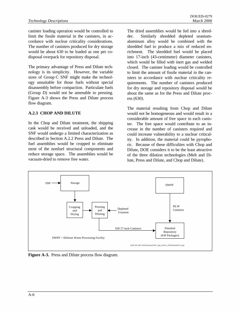
canister loading operation would be controlled tolimit the fissile material in the canisters, in ac-cordance with nuclear criticality considerations.The number of canisters produced for dry storagewould be about 630 to be loaded as one per co-disposal overpack for repository disposal.
The primary advantage of Press and Dilute tech-nology is its simplicity. However, the variablesizes of Group C SNF might make the technol-ogy unsuitable for those fuels without specialdisassembly before compaction. Particulate fuels(Group D) would not be amenable to pressing.Figure A-3 shows the Press and Dilute processflow diagram.
A.2.3 CHOP AND DILUTE
In the Chop and Dilute treatment, the shippingcask would be received and unloaded, and theSNF would undergo a limited characterization asdescribed in Section A.2.2 Press and Dilute. Thefuel assemblies would be cropped to eliminatemost of the nonfuel structural components andreduce storage space. The assemblies would bevacuum-dried to remove free water.
The dried assemblies would be fed into a shred-der. Similarly shredded depleted uranium-aluminum alloy would be combined with theshredded fuel to produce a mix of reduced en-richment. The shredded fuel would be placedinto 17-inch (43-centimeter) diameter canisters,which would be filled with inert gas and weldedclosed. The canister loading would be controlledto limit the amount of fissile material in the can-isters in accordance with nuclear criticality re-quirements. The number of canisters producedfor dry storage and repository disposal would beabout the same as for the Press and Dilute proc-ess (630).
The material resulting from Chop and Dilutewould not be homogeneous and would result in aconsiderable amount of free space in each canis-ter. The free space would contribute to an in-crease in the number of canisters required andcould increase vulnerability to a nuclear critical-ity. In addition, the material could be pyropho-ric. Because of these difficulties with Chop andDilute, DOE considers it to be the least attractiveof the three dilution technologies (Melt and Di-lute, Press and Dilute, and Chop and Dilute).
Figure A-3. Press and Dilute process flow diagram.
630 17-inch Canisters PotentialRepository
(630 Packages)
HLWCanisters
DWPF
Cropping and
Drying
SNF
Depleted Uranium
DWPF = Defense Waste Processing Facility
DOE-SR SNF EIS/Pubsonly/SNF_App_A/Grfx_APA/Embed/Fa-3.ppt
Pressingand
Diluting
Storage

DOE/EIS-0279March 2000 Technology Descriptions
A-7
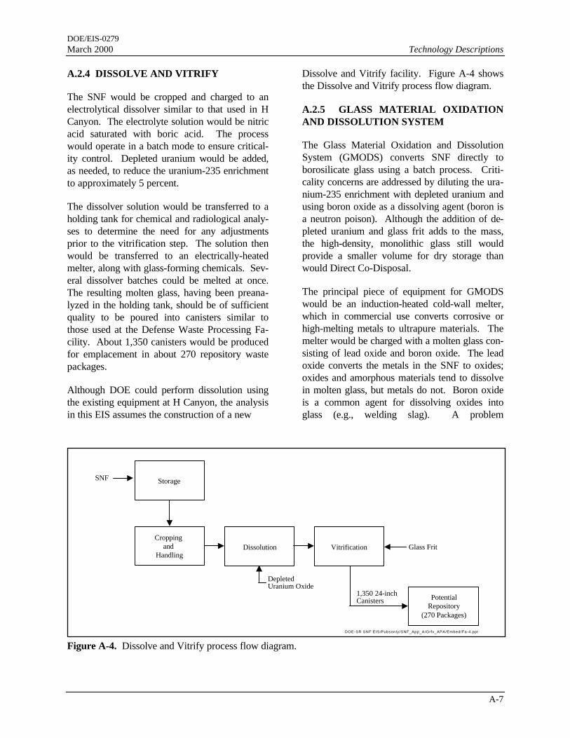
A.2.4 DISSOLVE AND VITRIFY
The SNF would be cropped and charged to anelectrolytical dissolver similar to that used in HCanyon. The electrolyte solution would be nitricacid saturated with boric acid. The processwould operate in a batch mode to ensure critical-ity control. Depleted uranium would be added,as needed, to reduce the uranium-235 enrichmentto approximately 5 percent.
The dissolver solution would be transferred to aholding tank for chemical and radiological analy-ses to determine the need for any adjustmentsprior to the vitrification step. The solution thenwould be transferred to an electrically-heatedmelter, along with glass-forming chemicals. Sev-eral dissolver batches could be melted at once.The resulting molten glass, having been preana-lyzed in the holding tank, should be of sufficientquality to be poured into canisters similar tothose used at the Defense Waste Processing Fa-cility. About 1,350 canisters would be producedfor emplacement in about 270 repository wastepackages.
Although DOE could perform dissolution usingthe existing equipment at H Canyon, the analysisin this EIS assumes the construction of a new
Dissolve and Vitrify facility. Figure A-4 showsthe Dissolve and Vitrify process flow diagram.
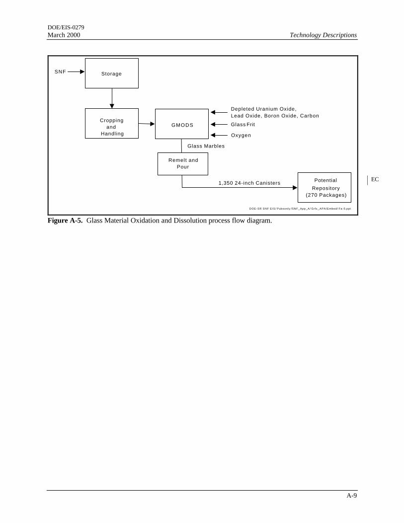
A.2.5 GLASS MATERIAL OXIDATIONAND DISSOLUTION SYSTEM
The Glass Material Oxidation and DissolutionSystem (GMODS) converts SNF directly toborosilicate glass using a batch process. Criti-cality concerns are addressed by diluting the ura-nium-235 enrichment with depleted uranium andusing boron oxide as a dissolving agent (boron isa neutron poison). Although the addition of de-pleted uranium and glass frit adds to the mass,the high-density, monolithic glass still wouldprovide a smaller volume for dry storage thanwould Direct Co-Disposal.
The principal piece of equipment for GMODSwould be an induction-heated cold-wall melter,which in commercial use converts corrosive orhigh-melting metals to ultrapure materials. Themelter would be charged with a molten glass con-sisting of lead oxide and boron oxide. The leadoxide converts the metals in the SNF to oxides;oxides and amorphous materials tend to dissolvein molten glass, but metals do not. Boron oxideis a common agent for dissolving oxides intoglass (e.g., welding slag). A problem
Figure A-4. Dissolve and Vitrify process flow diagram.
Dissolution
PotentialRepository
(270 Packages)
Vitrification Glass FritCropping
and Handling
DepletedUranium Oxide
1,350 24-inchCanisters
Storage
DOE-SR SNF EIS/Pubsonly/SNF_App_A/Grfx_APA/Embed/Fa-4.ppt
SNF

DOE/EIS-0279Technology Descriptions March 2000
A-8
with using lead oxide is its corrosivity, whichcould affect the service life of the melter.
As the SNF is fed into the melter, the aluminum,uranium, and other metals would be oxidized anddissolved in the molten glass. Uranium oxidesand other oxides would be directly dissolved.The oxidation of the metals converts the leadoxide to metallic lead, which sinks to the bottomof the melter.
The resulting glass mixture would not havequalities necessary for long-term durability, sosilicon oxide (glass frit) additions would be nec-essary to increase the durability. The siliconoxide would not be part of the initial meltercharge because its properties are not conduciveto rapid oxidation-dissolution of SNF. Unre-duced lead oxide could limit the durability of theglass, and increase volume, so carbon would beadded to the melt to reduce the excess lead oxide.
The glass melt would be decanted from the melterand formed into glass marbles. For criticalityand other practical reasons, the batch melts usingGMODS would not be large enough to fill a 24-inch (61-centimeter) diameter canister. There-fore, the glass marbles would be stored and
remelted, allowing a continuous pour to fill sev-eral 24-inch diameter canisters at a time. TheGMODS process would produce typically about1,350 canisters for emplacement in about 270repository packages.
After decanting the glass, the melter would berecharged with boron oxide and, if necessary,lead oxide. Oxygen would be piped into the sys-tem to convert the metallic lead at the bottom ofthe melter back to lead oxide. Lead would be anoxygen carrier that did not leave the system.
Radioactive offgases produced during this proc-ess would be filtered and treated appropriately.Figure A-5 shows the Glass Material Oxidationand Dissolution process flow diagram.
A.2.6 PLASMA ARC TREATMENT
The Plasma Arc Treatment technology uses aplasma torch to melt and oxidize the SNF inconjunction with depleted uranium oxide andother ceramic-forming materials as necessary.The fuel would be fed into the process withminimal sizing or pretreatment. The plasma arcwould cut the fuel assemblies into small piecesand heat the fuel to temperatures as high as

DOE/EIS-0279March 2000 Technology Descriptions
A-9
Repository(270 Packages)
Depleted Uranium Oxide,Lead Oxide, Boron Oxide, Carbon
1,350 24-inch Canisters
StorageSNF
Glass Frit
DOE-SR SNF EIS / Pubsonly /SNF_App_A/ Grfx _APA/Embed/ Fa -5.ppt
GMODSCropping
andHandling Oxygen
Remelt andPour
Glass Marbles
Potential
Figure A-5. Glass Material Oxidation and Dissolution process flow diagram.
EC

DOE/EIS-0279Technology Descriptions March 2000
A-10
1,600°C (2,900°F) to melt and oxidize it in arotating furnace. Ceramic material would beadded as necessary with the mixture homoge-nized by the torch. When melting and oxidationwere complete, the rotating furnace would slowand the melt would fall into molds prepared toreceive it.
Some types of SNF might not require the addi-tion of ceramic material to the process becausethe oxidation would produce a robust ceramicform from the fuel itself. Many metallic fuelswould, however, need some ceramic addition.Depleted uranium could be added to the processin almost any form to reduce the uranium-235enrichment. Criticality issues would be ad-dressed by limiting the process to batch runs ofpreselected quantities of fissile material, by theaddition of the depleted uranium, and by the ad-dition of neutron poisons if necessary. ThePlasma Arc treatment would produce about 490canisters to be contained in 98 repository pack-ages.
As with all processes that dissolve or melt theSNF, the Plasma Arc Treatment would produceradioactive offgases. These gases would be fil-tered and treated by appropriate means, with thefilter and treatment media recycled into the
plasma arc furnace for incorporation into the ce-ramic product. Figure A-6 shows the PlasmaArc Treatment process flow diagram.
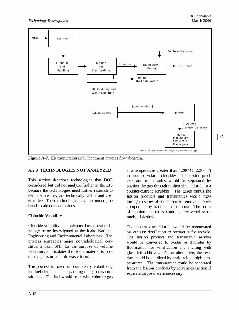
A.2.7 ELECTROMETALLURGICALTREATMENT
The Electrometallurgical Treatment processwould adapt a technology under development atthe Argonne National Laboratory for processingExperimental Breeder Reactor-II fuel and blanketassemblies. The process has been demonstratedfor the stainless steel-clad uranium alloy fuelsused in this reactor. The electrorefining processemploys a technology used in industry to producepure metals from impure metal feedstock. Thefeasibility of the Electrometallurgical Treatmentfor aluminum-based fuels has been tested in thelaboratory and is theoretically possible as con-ducted in the following two stages. An electrore-finer facility is available at the Idaho NationalEngineering and Environmental Laboratory totest development concepts.
Preparation
Before electrorefining, the fuel would be croppedand the end fittings discarded. The fuel assem-blies would be compacted and melted with
Repository(98 Packages)
Depleted Uranium OxideCroppingand
Handling
490 24-inch Canisters
StorageFuel
Glass Frit
DOE-SR SNF EIS / Pubsonly /SNF_App_A/ Grfx _APA/Embed/ Fa -6. ppt
Ceramic Melter
Potential
Figure A-6. Plasma Arc Treatment process flow diagram.
EC

DOE/EIS-0279March 2000 Technology Descriptions
A-11
silicon added to the melt to complex the uraniumand enhance its separation from aluminum in thesubsequent electrorefining step.
Melting would vaporize many volatile fissionproducts (e.g., cesium, rubidium, bromine, io-dine, xenon, and krypton), which, with the ex-ception of the noble gases, would be captured ina fibrous aluminosilicate trap. The molten fuelwould be poured into ingots that would becomethe anodes for processing in the next step in theelectrorefiner.
Aluminum Separation
The electrorefining process would first use alithium fluoride-potassium fluoride electrolyte toseparate the aluminum from the anode. Alumi-num and alkaline earth fission products woulddissolve out of the ingot; the aluminum wouldform a soluble compound of potassium aluminumhexafluoride (K3AlF6), which would travel to thecathode where it would be reduced to pure alu-minum metal. The alkaline earth fission productswould remain in the electrolyte. The aluminumdeposits on the cathode would be continuallyscraped off and collected.
Because some electrolyte salts would be en-trained with the aluminum, the aluminum wouldbe melted to separate the aluminum from thesalts. The melt would cool below the meltingpoint of the aluminum, and the salts would bepoured off and recycled. The aluminum wouldbe disposed as low-level waste.
Uranium Separation
After essentially all aluminum was removed fromthe anode, the actinides (primarily uranium), rareearths, and noble metals would remain. The an-ode would be placed in a second refiner that usedlithium fluoride, potassium fluoride, and uraniumtrifluoride salts as electrolytes. The uranium inthe anode present as a uranium silicide would beoxidized to uranium trifluoride and transported tothe cathode where it would be reduced to ura-nium metal. The ura-
nium metal deposits would be collected and sepa-rated from electrolyte salts as was the aluminum.
Salt Scrubbing
With the continued electrorefining of the SNF,alkaline earth fluorides would build up in thealuminum electrorefiner, and the rare earth andtransuranic fluorides would build up in the ura-nium electrorefiner. These waste products couldbe separated from the electrolyte by ion exchangeor chemical reduction and oxide precipitation.
Waste Treatment
The Electrometallurgical Treatment processwould produce several waste streams besidesaluminum: scrubbed alkaline earths, rare earths,transuranics, the metal remaining in the anodeafter uranium electrorefining, and the fibrousaluminosilicate filter used to collect volatile fis-sion products released during SNF melting.These wastes would be placed in an air oxidationfurnace to burn to an oxide powder with noblemetal fines dispersed in the powder. A smallglass melter would melt the oxide powder withglass-forming materials to produce a glass simi-lar to that produced in the Defense Waste Proc-essing Facility. The glass would be formed intomarbles for shipment to the Defense Waste Proc-essing Facility for incorporating into high-levelwaste glass logs. The electrometallurgical treat-ment would produce about 90 24-inch diametercanisters to be contained in 18 repository dis-posal packages.
Uranium Dilution
A small melter would melt the uranium metal andblend it with depleted uranium to produce a ura-nium enriched to about 5 percent uranium-235.This uranium could be sold as feedstock forcommercial nuclear fuel manufacture. Figure A-7 shows the Electrometallurgical Treatment pro-cess flow diagram.

DOE/EIS-0279Technology Descriptions March 2000
A-12
Meltingand
Electrorefining
(18 WastePackages)
Blend DownMelting
LEU CreditCropping
andHandling
AluminumLow-Level Waste
90 24-inchdiameter Canisters
Storage
Depleted Uranium
DWPF
DOE-SR SNF EIS/Pubsonly/SNF_App_A/Grfx_APA/Embed/Fa-7.ppt
SNF
Salt Scrubbing andWaste Oxidation
Glass Melting
[glass marbles]
Uranium
PotentialRepository
Figure A-7. Electrometallurgical Treatment process flow diagram.
A.2.8 TECHNOLOGIES NOT ANALYZED
This section describes technologies that DOEconsidered but did not analyze further in the EISbecause the technologies need further research todemonstrate they are technically viable and costeffective. These technologies have not undergonebench-scale demonstrations.
Chloride Volatility
Chloride volatility is an advanced treatment tech-nology being investigated at the Idaho NationalEngineering and Environmental Laboratory. Theprocess segregates major nonradiological con-stituents from SNF for the purpose of volumereduction, and isolates the fissile material to pro-duce a glass or ceramic waste form.
The process is based on completely volatilizingthe fuel elements and separating the gaseous con-stituents. The fuel would react with chlorine gas
at a temperature greater than 1,200°C (2,200°F)to produce volatile chlorides. The fission prod-ucts and transuranics would be separated bypassing the gas through molten zinc chloride in acounter-current scrubber. The gases minus thefission products and transuranics would flowthrough a series of condensers to remove chloridecompounds by fractional distillation. The seriesof uranium chlorides could be recovered sepa-rately, if desired.
The molten zinc chloride would be regeneratedby vacuum distillation to recover it for recycle.The fission product and transuranic residuewould be converted to oxides or fluorides byfluorination for vitrification and melting withglass frit additives. As an alternative, the resi-dues could be oxidized by boric acid at high tem-peratures. The transuranics could be separatedfrom the fission products by solvent extraction ifseparate disposal were necessary.
EC

DOE/EIS-0279March 2000 Technology Descriptions
A-13
Although there has been no experimental workwith this technology, DOE has determined thatthe time and expense to overcome the technicalrisks would be too great. Therefore, this tech-nology is not analyzed further in this EIS.
Can-in-Canister
The Can-in-Canister concept was developed todispose of excess plutonium. The method wouldplace an array of stainless-steel cans containingplutonium ceramic in a high-level waste canister.The molten high-level waste glass would bepoured around the cans. The placement structurewould maintain spacing between the cans and thewall of the canister. The Can-in-Canister methodis a potentially favorable method for disposing ofplutonium because the radiation fields emanatingfrom the high-level waste would discourage in-trusion to recover the plutonium. Plutonium it-self does not produce high radiation fields.
Can-in-Canister technology is not as attractivefor SNF. Most SNF produces high radiationfields that would render recovery difficult andthus would not need the added deterrent of high-level waste surrounding it. In addition, becausethe melting point of aluminum is less than that ofglass in high-level waste vitrification operations,the aluminum fuel could melt in the cans as thecanister was being filled with the molten high-level waste glass. Finally, it is not certain theintegrity of the glass could be maintained if itcontained large voids - in common with the dis-posal of plutonium in glass.
The Direct Co-Disposal technology provides allthe benefits of Can-in-Canister technology with-out the disadvantages. The SNF would be sur-rounded by high-level waste glass canisters,ensuring that HLW radiation fields would renderthe SNF inaccessible for long periods of time.The fuel would not displace any high-level wastecanisters, thus eliminating the need for additionalrepository waste packages. Also, the SNF wouldnot be heated near or over its melting point. Forthese reasons, the Can-in-Canister process wasnot analyzed in this EIS.
A.3 Conventional Processing
As discussed in Chapter 2, DOE could use F orH Canyon to process SNF. F Canyon histori-cally has been used to recover depleted uraniumand plutonium from depleted uranium target ma-terials irradiated in SRS reactors. H Canyonhistorically has been used to recover highly-enriched uranium and neptunium from SNF. Thefollowing paragraphs are applicable to operationsin H Canyon. F Canyon operations would besimilar.
At the SNF wet storage basins, the fuel would beplaced in aluminum bundle sleeves. For materi-als test reactor-like fuel elements, the fuel wouldbe stacked four to five elements high in the bun-dle sleeve. Before shipment to H Canyon, thebundle sleeves would be assembled into largerarrays to make a complete bundle. The size ofthe array would be determined by shipping caskand the size of the dissolver, and by criticalityconcerns. Bundling would facilitate handling andmaintain a noncritical geometry as the fuel wascharged to the dissolver. The storage racks in theReceiving Basin for Offsite Fuel and L-ReactorDisassembly Basin use bundle sleeves to maxi-mize storage space.
The SNF would be transported in a water-filledcask on a rail car from either L-Reactor Disas-sembly Basin or the Receiving Basin for OffsiteFuel. Inside the airlock doors to the hot canyon,the fuel would be unloaded and placed in an in-terim wet storage basin to await processing. Thebundles of SNF would be fed into the top of adissolver tank. The fuel would be dissolved inhot nitric acid, producing a solution of highly-enriched uranium, fission products, aluminum,and small amounts of transuranic materials suchas neptunium and plutonium.
Head-end processing would use two clarificationsteps to remove undesirable contaminants thatcould impede the subsequent solvent extractionprocess. Gelatin would be added to precipitatesilica and other impurities. The

DOE/EIS-0279Technology Descriptions March 2000
A-14
clarified solution would be adjusted with nitricacid and water in preparation for the first-cyclesolvent extraction. The waste stream generatedfrom the head-end process would be chemicallyneutralized and sent to the high-level waste tanks.
The first-cycle solvent extraction in the hot can-yon would remove the fission products and otherimpurities, and then separate the uranium fromthe other actinides. Nonuranium actinides wouldnot be recovered. If necessary, a second-cyclesolvent extraction could further purify the ura-nium solution. The solvent would be recoveredfor reuse, the acid solution containing the fissionproducts would be neutralized and transferred tothe high-level waste tanks, and the uranium in auranyl nitrate solution would be transferred to H-Area tanks to be blended down to about 5 percenturanium-235. The uranyl nitrate could be madeavailable for commercial sale.
Chemical processing would generate liquid high-level waste, for which SRS has existing storageand treatment facilities. Impacts associated withthe operation of these facilities are described inthe Interim Management of Nuclear Materials(IMNM) EIS (DOE 1995) and the DefenseWaste Processing Facility (DWPF) SupplementalEIS (DOE 1994). Chapter 5 summarizes theresults from the IMNM and DWPF EISs. Forcompleteness, the following paragraphs summa-rize high-level waste processing at SRS.
Chemical processing produces an acidic solutionthat is neutralized before transfer to large tanksin the F- and H-Area Tank Farms. During stor-age to allow short-lived radionuclides to decay,the insoluble components of the alkaline waste
settle to the bottom of the tank to form a sludgelayer. The liquid supernate is decanted andevaporated to concentrate it into a crystallizedsalt. Evaporator overheads are condensed anddischarged to the F/H Effluent Treatment Facil-ity.
In preparation for final disposal, the salt is redis-solved and processed to separate it into high-radioactivity and low-radioactivity fractions.The high-radioactivity fraction is sent to the De-fense Waste Processing Facility where it is in-corporated into a glass form for eventual disposalin a geologic repository. The low-radioactivityfraction is sent to the Saltstone Manufacturingand Disposal Facility where it is mixed with ce-ment, slag, and flyash to produce a cementatiousgrout solidified in onsite disposal vaults.
The sludge in the high-level waste tanks, afterwashing to remove dissolved salts, also is trans-ferred to the Defense Waste Processing Facilityfor incorporation into the high-level waste glassform for repository disposal. About 150 canis-ters of 24-inch diameter would be produced dur-ing the conventional processing of spent nuclearfuel.
Figure A-8 shows the Conventional Processingflow diagram.

DOE/EIS-0279March 2000 Technology Descriptions
A-15
DissolverSNF
DU (F Canyon only)
First CycleSolvent Extraction
HLW
Head EndSecond Cycle
Solvent Extraction(If needed)
Uranyl NitrateStorage Tanks
recycle
uranium
DWPFRepository
DU (H Canyon only)
DWPF = Defense Waste Processing Facil itySNF = Spent Nuclear FuelDU = Depleted UraniumHLW = High Level Waste
D O E - S R S N F E I S /P u b s o n l y /S N F _ A p p _ A /Gr fx_ A P A / E m b e d /F a -8.pp t
Potential
Figure A-8. Conventional Processing flow diagram.
EC

DOE/EIS-0279Technology Descriptions March 2000
A-16
References
DOE (U.S. Department of Energy), 1994, Final Supplemental Environmental Impact Statement, DefenseWaste Processing Facility, DOE/EIS-0082-S, Savannah River Operations Office, Aiken, SouthCarolina.
DOE (U.S. Department of Energy), 1995, Final Environmental Impact Statement, Interim Management ofNuclear Materials, DOE-EIS-0220, Savannah River Operations Office, Aiken, South Carolina.
DOE (U.S. Department of Energy), 1996, Technical Strategy for the Treatment, Packaging, and Disposalof Aluminum-Based Spent Nuclear Fuel, A Report of the Research Reactor Spent Nuclear Fuel TaskTeam, Volume 1, Washington, D.C.

DOE/EIS-0279March 2000 Technology Descriptions
A-17
aluminum-based SNF, 2
canyon, 12, 13
cesium, 10
Chop and Dilute, 6
conventional processing, 13
criticality, 2, 6, 7, 8, 12
Defense Waste Processing Facility, 7, 10, 13
Direct Disposal, 1, 2, 3
Dissolve and Vitrify, 7
DOE, 1, 2, 6, 7, 11, 12, 13
DWPF, 13
Electrometallurgical Treatment, 9, 10, 11
Experimental Breeder Reactor-II fuel, 9
F Canyon, 12
geologic repository, 13
Group A, 1
Group B, 1
Group C, 6
Group D, 6
H Canyon, 7, 12
high-level waste, 2, 10, 12, 13
highly-enriched uranium, 12
Idaho National Engineering and Environmental
Laboratory, 9, 11
low-level waste, 10
L-Reactor Disassembly Basin, 12
materials test reactor-like fuels, 1
Melt and Dilute, 2, 4, 6
NRC, 2
Nuclear Regulatory Commission, 2
offgas, 2
Plasma Arc Treatment, 8, 9
plutonium, 12
Plutonium, 12
Press and Dilute, 5, 6
process, 1, 2, 3, 4, 6, 7, 8, 9, 10, 11, 12, 13
Receiving Basin for Offsite Fuel, 12
repository, 2, 6, 7, 8, 9, 10, 12, 13
Transfer and Storage Facility, 1
Transfer, Storage, and Treatment Facility, 1
U.S. Department of Energy, 1
uranium, 1, 2, 5, 7, 8, 9, 10, 11, 12, 13
vitrification, 7, 11, 12

Cask Handl ing
• Receive and wash down casks.
• Vent, sample, and remove bolts.
• Transfer cask to hot cell.
Primary Character izat ion
• Visual, dimensions, weight.
• Thermal
• Gamma, neutron.
Decanning
• Cut ends from cans or
tubes, remove SNF.
• Cut scrap to 4' lengths.
Cropping
• Cut non fuel-bearing ends
from SNF.• Dissassemble HFIR outer
cores into quarters.
Detai led Characterizat ion
• More rigorous
measurements of selected
SNF.
• Gamma, neutron.
• Thermal.
Basket Loading
Load SNF and/or cans into baskets.
Verif ication/Test
• Perform final characterization of loaded
basket.
• Gamma, neutron, thermal, weight.
Canister Loading/Transfer
• Place basket into canister/transfer cask
and place shield plug into canister.
• Remove canister/transfer cask from hotcell and place in a canister preparation
station.
Canister Prep/Closure
• Decontaminate exposed surfaces of
transfer cask.
• Weld shield plug in canister; inspect weld.
• Vacuum dry, fi l l with inert gas, and leak-
test canister.
• Weld outer lid. Bolt top lid on transfer
cask.
Transfer to Road-Ready Storage
• Storage capacity for 1,400 canisters.
(Direct Disposal 1,100 canisters)
Figure A-1. Direct Disposal/Direct Co-Disposal process flow diagram.
Technology Descriptions
NW SNF EIS/PubsOnly/SNFApp_a/Grfx_apa/FA-1.ppt
A-3
DOE/EIS-0279March 2000
Legend:
Outside hot cell
Inside hot cell
Canning
• Place failed SNF in can.
• Seat lid into can; no weld.
SNF = Spent Nuclear Fuel
HFIR = High Flux Isotope Reactor
Unloading/Lag Storage
• Remove cask l id.• Remove each assembly, can, or
basket.
• Attach ID label to assembly or can,
and place in Lag Storage Racks.
• Return cask to cask handling area for
decontamination.
Unloading/Lag Storage
• Remove cask l id.
• Remove each assembly, can, orbasket.
• Attach ID label to assembly or can, and
place in Lag Storage Racks.
• Return cask to cask handling area for
decontamination.
Cask Handl ing
• Receive and wash down casks.
• Vent; sample; and remove bolts.
• Transfer cask to hot cell.
Characterizat ion
• Visual, weight.
Decanning
• Cut ends from cans or
tubes, remove SNF.
• Cut scrap to 4' lengths.
Cropping
• Cut non fuel-bearing ends
from SNF (non-aluminumSNF and some aluminum
SNF with excessive
aluminum for melter).
Melt and Di lute
• Select SNF for melter batch; determine
"recipe."
• Preheat/dry SNF.
• Melt Al, DU, and SNF in induction
melter.
• Sample molten alloy and analyze with
mass spectrometer; make any
necessary adjustments.
• Cast al loy into Primary Waste Form,
approximately 16" OD by 33" maximumlength.
Basket Loading
• Load primary waste form into baskets.
Verif ication/Test
• Perform final characterization of loaded
basket.
• Gamma, neutron, thermal, weight.
Canister Loading/Transfer
• Place basket into canister/transfer caskand place shield plug in canister.
• Remove canister/transfer cask from hot
cell and place in a canister preparation
station.
Canister Prep/Closure
• Decontaminate exposed surfaces oftransfer cask.
• Weld shield plug in canister; inspect weld.
• Evacuate, fil l with inert gas, and leak-test
canister.
• Weld outer lid. Bolt top lid on transfer
cask.
Transfer to Road-Ready Storage
• Storage capacity for 400 canisters.
Figure A-2. Melt and Dilute process flow diagram.
Technology Descriptions
A-4
Legend:
Outside hot cell
Inside hot cell
DOE/EIS-0279March 2000
NW SNF EIS/PubsOnly/SNF_App_A/Grfx_APA/FA-2.ppt
DU = Depleted UraniumAL = AluminumOD = Outside Diameter
DOE/EIS-0279Technology Descriptions March 2000
A-6
canister loading operation would be controlled tolimit the fissile material in the canisters, in ac-cordance with nuclear criticality considerations.The number of canisters produced for dry storagewould be about 630 to be loaded as one per co-disposal overpack for repository disposal.
The primary advantage of Press and Dilute tech-nology is its simplicity. However, the variablesizes of Group C SNF might make the technol-ogy unsuitable for those fuels without specialdisassembly before compaction. Particulate fuels(Group D) would not be amenable to pressing.Figure A-3 shows the Press and Dilute processflow diagram.
A.2.3 CHOP AND DILUTE
In the Chop and Dilute treatment, the shippingcask would be received and unloaded, and theSNF would undergo a limited characterization asdescribed in Section A.2.2 Press and Dilute. Thefuel assemblies would be cropped to eliminatemost of the nonfuel structural components andreduce storage space. The assemblies would bevacuum-dried to remove free water.
The dried assemblies would be fed into a shred-der. Similarly shredded depleted uranium-aluminum alloy would be combined with theshredded fuel to produce a mix of reduced en-richment. The shredded fuel would be placedinto 17-inch (43-centimeter) diameter canisters,which would be filled with inert gas and weldedclosed. The canister loading would be controlledto limit the amount of fissile material in the can-isters in accordance with nuclear criticality re-quirements. The number of canisters producedfor dry storage and repository disposal would beabout the same as for the Press and Dilute proc-ess (630).
The material resulting from Chop and Dilutewould not be homogeneous and would result in aconsiderable amount of free space in each canis-ter. The free space would contribute to an in-crease in the number of canisters required andcould increase vulnerability to a nuclear critical-ity. In addition, the material could be pyropho-ric. Because of these difficulties with Chop andDilute, DOE considers it to be the least attractiveof the three dilution technologies (Melt and Di-lute, Press and Dilute, and Chop and Dilute).
Figure A-3. Press and Dilute process flow diagram.
630 17-inch Canisters PotentialRepository
(630 Packages)
HLWCanisters
DWPF
Cropping and
Drying
SNF
Depleted Uranium
DWPF = Defense Waste Processing Facility
DOE-SR SNF EIS/Pubsonly/SNF_App_A/Grfx_APA/Embed/Fa-3.ppt
Pressingand
Diluting
Storage
DOE/EIS-0279March 2000 Technology Descriptions
A-7
A.2.4 DISSOLVE AND VITRIFY
The SNF would be cropped and charged to anelectrolytical dissolver similar to that used in HCanyon. The electrolyte solution would be nitricacid saturated with boric acid. The processwould operate in a batch mode to ensure critical-ity control. Depleted uranium would be added,as needed, to reduce the uranium-235 enrichmentto approximately 5 percent.
The dissolver solution would be transferred to aholding tank for chemical and radiological analy-ses to determine the need for any adjustmentsprior to the vitrification step. The solution thenwould be transferred to an electrically-heatedmelter, along with glass-forming chemicals. Sev-eral dissolver batches could be melted at once.The resulting molten glass, having been preana-lyzed in the holding tank, should be of sufficientquality to be poured into canisters similar tothose used at the Defense Waste Processing Fa-cility. About 1,350 canisters would be producedfor emplacement in about 270 repository wastepackages.
Although DOE could perform dissolution usingthe existing equipment at H Canyon, the analysisin this EIS assumes the construction of a new
Dissolve and Vitrify facility. Figure A-4 showsthe Dissolve and Vitrify process flow diagram.
A.2.5 GLASS MATERIAL OXIDATIONAND DISSOLUTION SYSTEM
The Glass Material Oxidation and DissolutionSystem (GMODS) converts SNF directly toborosilicate glass using a batch process. Criti-cality concerns are addressed by diluting the ura-nium-235 enrichment with depleted uranium andusing boron oxide as a dissolving agent (boron isa neutron poison). Although the addition of de-pleted uranium and glass frit adds to the mass,the high-density, monolithic glass still wouldprovide a smaller volume for dry storage thanwould Direct Co-Disposal.
The principal piece of equipment for GMODSwould be an induction-heated cold-wall melter,which in commercial use converts corrosive orhigh-melting metals to ultrapure materials. Themelter would be charged with a molten glass con-sisting of lead oxide and boron oxide. The leadoxide converts the metals in the SNF to oxides;oxides and amorphous materials tend to dissolvein molten glass, but metals do not. Boron oxideis a common agent for dissolving oxides intoglass (e.g., welding slag). A problem
Figure A-4. Dissolve and Vitrify process flow diagram.
Dissolution
PotentialRepository
(270 Packages)
Vitrification Glass FritCropping
and Handling
DepletedUranium Oxide
1,350 24-inchCanisters
Storage
DOE-SR SNF EIS/Pubsonly/SNF_App_A/Grfx_APA/Embed/Fa-4.ppt
SNF
DOE/EIS-0279March 2000 Technology Descriptions
A-9
Repository(270 Packages)
Depleted Uranium Oxide,Lead Oxide, Boron Oxide, Carbon
1,350 24-inch Canisters
StorageSNF
Glass Frit
DOE-SR SNF EIS / Pubsonly /SNF_App_A/ Grfx _APA/Embed/ Fa -5.ppt
GMODSCropping
andHandling Oxygen
Remelt andPour
Glass Marbles
Potential
Figure A-5. Glass Material Oxidation and Dissolution process flow diagram.
EC

DOE/EIS-0279Technology Descriptions March 2000
A-10
1,600°C (2,900°F) to melt and oxidize it in arotating furnace. Ceramic material would beadded as necessary with the mixture homoge-nized by the torch. When melting and oxidationwere complete, the rotating furnace would slowand the melt would fall into molds prepared toreceive it.
Some types of SNF might not require the addi-tion of ceramic material to the process becausethe oxidation would produce a robust ceramicform from the fuel itself. Many metallic fuelswould, however, need some ceramic addition.Depleted uranium could be added to the processin almost any form to reduce the uranium-235enrichment. Criticality issues would be ad-dressed by limiting the process to batch runs ofpreselected quantities of fissile material, by theaddition of the depleted uranium, and by the ad-dition of neutron poisons if necessary. ThePlasma Arc treatment would produce about 490canisters to be contained in 98 repository pack-ages.
As with all processes that dissolve or melt theSNF, the Plasma Arc Treatment would produceradioactive offgases. These gases would be fil-tered and treated by appropriate means, with thefilter and treatment media recycled into the
plasma arc furnace for incorporation into the ce-ramic product. Figure A-6 shows the PlasmaArc Treatment process flow diagram.
A.2.7 ELECTROMETALLURGICALTREATMENT
The Electrometallurgical Treatment processwould adapt a technology under development atthe Argonne National Laboratory for processingExperimental Breeder Reactor-II fuel and blanketassemblies. The process has been demonstratedfor the stainless steel-clad uranium alloy fuelsused in this reactor. The electrorefining processemploys a technology used in industry to producepure metals from impure metal feedstock. Thefeasibility of the Electrometallurgical Treatmentfor aluminum-based fuels has been tested in thelaboratory and is theoretically possible as con-ducted in the following two stages. An electrore-finer facility is available at the Idaho NationalEngineering and Environmental Laboratory totest development concepts.
Preparation
Before electrorefining, the fuel would be croppedand the end fittings discarded. The fuel assem-blies would be compacted and melted with
Repository(98 Packages)
Depleted Uranium OxideCroppingand
Handling
490 24-inch Canisters
StorageFuel
Glass Frit
DOE-SR SNF EIS / Pubsonly /SNF_App_A/ Grfx _APA/Embed/ Fa -6. ppt
Ceramic Melter
Potential
Figure A-6. Plasma Arc Treatment process flow diagram.
EC
DOE/EIS-0279Technology Descriptions March 2000
A-12
Meltingand
Electrorefining
(18 WastePackages)
Blend DownMelting
LEU CreditCropping
andHandling
AluminumLow-Level Waste
90 24-inchdiameter Canisters
Storage
Depleted Uranium
DWPF
DOE-SR SNF EIS/Pubsonly/SNF_App_A/Grfx_APA/Embed/Fa-7.ppt
SNF
Salt Scrubbing andWaste Oxidation
Glass Melting
[glass marbles]
Uranium
PotentialRepository
Figure A-7. Electrometallurgical Treatment process flow diagram.
A.2.8 TECHNOLOGIES NOT ANALYZED
This section describes technologies that DOEconsidered but did not analyze further in the EISbecause the technologies need further research todemonstrate they are technically viable and costeffective. These technologies have not undergonebench-scale demonstrations.
Chloride Volatility
Chloride volatility is an advanced treatment tech-nology being investigated at the Idaho NationalEngineering and Environmental Laboratory. Theprocess segregates major nonradiological con-stituents from SNF for the purpose of volumereduction, and isolates the fissile material to pro-duce a glass or ceramic waste form.
The process is based on completely volatilizingthe fuel elements and separating the gaseous con-stituents. The fuel would react with chlorine gas
at a temperature greater than 1,200°C (2,200°F)to produce volatile chlorides. The fission prod-ucts and transuranics would be separated bypassing the gas through molten zinc chloride in acounter-current scrubber. The gases minus thefission products and transuranics would flowthrough a series of condensers to remove chloridecompounds by fractional distillation. The seriesof uranium chlorides could be recovered sepa-rately, if desired.
The molten zinc chloride would be regeneratedby vacuum distillation to recover it for recycle.The fission product and transuranic residuewould be converted to oxides or fluorides byfluorination for vitrification and melting withglass frit additives. As an alternative, the resi-dues could be oxidized by boric acid at high tem-peratures. The transuranics could be separatedfrom the fission products by solvent extraction ifseparate disposal were necessary.
EC

DOE/EIS-0279March 2000 Technology Descriptions
A-15
DissolverSNF
DU (F Canyon only)
First CycleSolvent Extraction
HLW
Head EndSecond Cycle
Solvent Extraction(If needed)
Uranyl NitrateStorage Tanks
recycle
uranium
DWPFRepository
DU (H Canyon only)
DWPF = Defense Waste Processing Facil itySNF = Spent Nuclear FuelDU = Depleted UraniumHLW = High Level Waste
D O E - S R S N F E I S /P u b s o n l y /S N F _ A p p _ A /Gr fx_ A P A / E m b e d /F a -8.pp t
Potential
Figure A-8. Conventional Processing flow diagram.
EC

APPENDIX B
IDENTIFICATION AND RESOLUTION OFSAVANNAH RIVER SITE SPENT NUCLEAR FUEL
VULNERABILITIES

DOE/EIS-0279 Identification and Resolution of Savannah River SiteMarch 2000 Spent Nuclear Fuel Vulnerabilities
B-iii
TABLE OF CONTENTS
Section Page
B.1 Purpose .......................................................................................................................... B-1B.2 Introduction and Background .......................................................................................... B-1B.3 Spent Fuel Working Group ............................................................................................. B-1B.4 Defense Nuclear Facilities Safety Board Recommendation 94-1....................................... B-2B.5 DNFSB January 1995 SRS Spent Fuel Vulnerability Assessment .................................... B-12B.6 DNFSB June 1995 SRS Spent Fuel Vulnerability Assessment ......................................... B-15B.7 DNFSB 1996 SRS Spent Fuel Handling Assessment ....................................................... B-15References ................................................................................................................................. B-17
List of Tables
Table Page
B-1 SRS vulnerabilities identified in Spent Nuclear Fuel Working Group Report. ................... B-3B-2 Status of Savannah River Site Vulnerability Corrective Action Plans. .............................. B-4B-3 Applicability of Defense Nuclear Facilities Safety Board Recommendation 94-1
to SRS............................................................................................................................ B-12B-4 Vulnerabilities identified in the January 1995 Defense Nuclear Facilities Safety Board
Trip Report..................................................................................................................... B-15B-5 Vulnerabilities identified in the June 1995 Defense Nuclear Facilities Safety Board
Trip Report..................................................................................................................... B-16B-6 Vulnerabilities identified in the 1996 Defense Nuclear Facilities Safety Board
Trip Report..................................................................................................................... B-18


DOE/EIS-0279 Identification and Resolution of Savannah River SiteMarch 2000 Spent Nuclear Fuel Vulnerabilities
B-1
APPENDIX B. IDENTIFICATION AND RESOLUTION OF SAVANNAHRIVER SITE SPENT NUCLEAR FUEL VULNERABILITIES
B.1 Purpose
The end of the Cold War brought an end to activeefforts in the United States to produce nuclearweapons materials such as plutonium. As a con-sequence, nuclear materials produced for weap-ons have been stored temporarily for prolongedperiods in systems and under conditions notoriginally designed for long-term storage. Pro-longed storage in systems and under conditionsdesigned for short-term storage has degraded theintegrity of some of these materials and has led toconcerns about safety. These concerns have beendocumented in reports by both the U.S. Depart-ment of Energy (DOE) and the Defense NuclearFacilities Safety Board (DNFSB). The purposeof this appendix is to provide a compilation ofspent nuclear fuel (SNF) storage problems (vul-nerabilities) specific to the Savannah River Site(SRS), their recommended corrective actions, andthe current status of those corrective actions.
B.2 Introduction and Background
For about 30 years, DOE operated heavy-waterreactors at SRS for the production of defensenuclear materials. Low-temperature reactor op-eration allowed the use of aluminum-clad, alumi-num-alloy fuel and aluminum-clad targetmaterials. This reactor design facilitated bothfuel and target fabrication and subsequent proc-essing. At the end of a reactor cycle, the fuel andtargets were normally discharged to cooling ba-sins and stored for as long as 18 months prior toprocessing.
In the past, the SRS processed SNF and otherreactor-irradiated nuclear materials (RINM) torecover plutonium, tritium, and other isotopes. InApril 1992, with chemical separations activitiesalready temporarily suspended, DOE imple-mented a decision to phase out defense-relatedchemical separation activities at the SRS. Proc-essing of the “in-process” RINM was not com-pleted. Facilities designed, constructed, and
operated to store RINM for relatively short peri-ods had to store it for relatively long periodspending decisions on the disposition of the mate-rials.
B.3 Spent Fuel Working Group
In August 1993, the Secretary of Energy com-missioned a comprehensive baseline assessmentof the environmental, safety, and health (ES&H)vulnerabilities associated with the storage of re-actor-irradiated nuclear materials in the DOEcomplex. In October 1993, a multidisciplinarySpent Fuel Working Group, comprised of DOEand contractor employees, assessed 66 facilitieson 11 sites. Eight SRS facilities that containedRINM were assessed. The facilities includedboth wet and dry storage systems. The assess-ment’s objective was to provide an itemized in-ventory of RINM and an initial assessment ofES&H vulnerabilities associated with the currentstorage and handling of these materials.
DOE defined vulnerabilities as conditions orweaknesses that could lead to radiation exposureto the public, unnecessary or increased exposureto the workers, or release of radioactive materialsto the environment. The loss of institutionalcontrols, such as cessation of facility funding orreductions in facility maintenance and control,could also cause vulnerabilities. Reactor-irradiated nuclear material was defined as spentnuclear fuel and irradiated nuclear targets fromproduction and research reactors; however, it didnot include fuel currently in active reactors orirradiated structural materials (other than fuelcladding).
The assessment focused on determining ES&Hvulnerabilities and presenting factual informa-tion. In general, DOE did not identify or recom-mend future corrective actions, but did assesscorrective actions already under way. Evalua-tions were made of facilities, structures, systems,operating conditions, and procedures necessary to

Identification and Resolution of Savannah River Site DOE/EIS-0279Spent Nuclear Fuel Vulnerabilities March 2000
B-2
protect the workers, the public, and the environ-ment during the storage and in-facility handlingof reactor-irradiated nuclear material.
On December 7, 1993, the Working Group re-leased Spent Fuel Working Group Report onInventory and Storage of the Department’sSpent Nuclear Fuel and Other Reactor Irradi-ated Nuclear Materials and Their Environ-mental, Safety, and Health Vulnerabilities (DOE1993) (“The Working Group Report,” Vol-umes I, II and III). Volume I summarized thefindings, including: (1) the characteristics andinventory of reactor-irradiated nuclear material;(2) ES&H vulnerabilities associated with differ-ent storage options; (3) five generic issues com-mon to many storage facilities; and(4) identification of eight facilities requiring pri-ority management attention, including the SRS L-and K-Reactor Disassembly Basins.
Volume II of the Working Group Report containsWorking Group Assessment Team reports foreach site, Vulnerability Development forms, anddocuments used by the Working Group Assess-ment Team as information sources. Volume IIcategorized vulnerabilities based on the periodduring which it was recommended that the vul-nerability be addressed. For each of the eightSRS facilities, vulnerabilities were grouped intoone of three time periods for management atten-tion: less than 1 year, 1 to 5 years, and morethan 5 years.
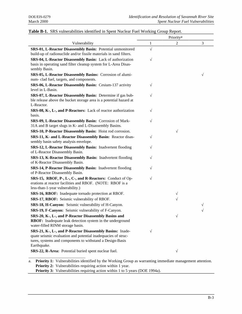
Volume II identified 21 SRS vulnerabilities. Atwenty-second vulnerability was identified later.When DOE reviewed the ES&H vulnerabilities,it determined that two (SRS-2 and SRS-3) werenot vulnerabilities and obtained agreement fromthe working group assessors. Table B-1 lists theSRS vulnerabilities and their assigned priorities.
Fifteen vulnerabilities warranting priority man-agement attention, including one potential vul-nerability, were identified for the SRS L-, K-,and P-Reactor Disassembly Basins. Four major
vulnerabilities and one generic vulnerability wereidentified for the Receiving Basin for Offsite Fuel(RBOF). The Reactor Division DisassemblyBasin Management Plan (Burke 1993) addressedand provided resolution of the vulnerabilitiesidentified for the reactor disassembly basins andRBOF. A February 21, 1997 memorandum re-ports on the corrective action closure package forthe reactor disassembly basins and RBOF vul-nerabilities (Burke 1997).
In February 1994, DOE released the first phaseof a three-phased plan to remedy vulnerabilitiesassociated with the storage of spent fuel and irra-diated materials. The Plan of Action to ResolveSpent Nuclear Fuel Vulnerabilities, Phase I(DOE 1994a) described actions that had beencompleted or for which no major funding or pol-icy issues existed. After the Phase I report wasissued, DOE resolved most funding issues asso-ciated with SNF vulnerabilities. The Phase IIPlan of Action (DOE 1994b), published in April1994, was the product of follow-on work to thePhase I report.
The Phase III Plan of Action (DOE 1994c), thesecond update to the original Plan of Action, wasissued in October 1994. The Phase III reportfocused on the resolution of critical policy issuesand incorporated stakeholder comments on theoriginal Plan of Action and the first update. Ta-ble B-2 lists the Phase I, II, and III correctiveaction plans and their reported status.
B.4 Defense Nuclear FacilitiesSafety Board Recommendation 94-1
In May 1994, the DNFSB issued Recommenda-tion 94-1, Improved Schedule for Remediation inthe Defense Nuclear Facilities Complex(DNFSB 1994). The Board expressed its con-cern that imminent hazards could arise during thenext 2 to 3 years unless problems related to thestate of reactor-irradiated nuclear material re-maining from the production of nuclear weaponswere resolved.
DOE/EIS-0279 Identification and Resolution of Savannah River SiteMarch 2000 Spent Nuclear Fuel Vulnerabilities
B-3
Table B-1. SRS vulnerabilities identified in Spent Nuclear Fuel Working Group Report.Prioritya
Vulnerability 1 2 3
SRS-01, L-Reactor Disassembly Basin: Potential unmonitoredbuild-up of radionuclide and/or fissile materials in sand filters.
√
SRS-04, L-Reactor Disassembly Basin: Lack of authorizationbasis in operating sand filter cleanup system for L-Area Disas-sembly Basin.
√
SRS-05, L-Reactor Disassembly Basins: Corrosion of alumi-num- clad fuel, targets, and components.
√
SRS-06, L-Reactor Disassembly Basin: Cesium-137 activitylevel in L-Basin.
√
SRS-07, L-Reactor Disassembly Basin: Determine if gas bub-ble release above the bucket storage area is a potential hazard atL-Reactor.
√
SRS-08, K-, L-, and P-Reactors: Lack of reactor authorizationbasis.
√
SRS-09, L-Reactor Disassembly Basin: Corrosion of Mark-31A and B target slugs in K- and L-Disassembly Basins.
√
SRS-10, P-Reactor Disassembly Basin: Hoist rod corrosion. √SRS-11, K- and L-Reactor Disassembly Basin: Reactor disas-sembly basin safety analysis envelope.
√
SRS-12, L-Reactor Disassembly Basin: Inadvertent floodingof L-Reactor Disassembly Basin.
√
SRS-13, K-Reactor Disassembly Basin: Inadvertent floodingof K-Reactor Disassembly Basin.
√
SRS-14, P-Reactor Disassembly Basin: Inadvertent floodingof P-Reactor Disassembly Basin.
√
SRS-15, RBOF, P-, L-, C-, and R-Reactors: Conduct of Op-erations at reactor facilities and RBOF. (NOTE: RBOF is aless-than-1-year vulnerability.)
√
SRS-16, RBOF: Inadequate tornado protection at RBOF. √SRS-17, RBOF: Seismic vulnerability of RBOF. √SRS-18, H-Canyon: Seismic vulnerability of H-Canyon. √SRS-19, F-Canyon: Seismic vulnerability of F-Canyon. √SRS-20, K-, L-, and P-Reactor Disassembly Basins andRBOF: Inadequate leak detection system in the undergroundwater-filled RINM storage basin.
√
SRS-21, K-, L-, and P-Reactor Disassembly Basins: Inade-quate seismic evaluation and potential inadequacies of struc-tures, systems and components to withstand a Design-BasisEarthquake.
√
SRS-22, R-Area: Potential buried spent nuclear fuel. √ a. Priority 1: Vulnerabilities identified by the Working Group as warranting immediate management attention.
Priority 2: Vulnerabilities requiring action within 1 year.Priority 3: Vulnerabilities requiring action within 1 to 5 years (DOE 1994a).

Identification and Resolution of Savannah River Site DOE/EIS-0279Spent Nuclear Fuel Vulnerabilities March 2000
B-4
Table B-2. Status of Savannah River Site Vulnerability Corrective Action Plans.Identified vulnerabilities Corrective action plans Status
SRS-1: Potential unmonitored buildupof radionuclide/fissile material in sandfilters. (L-Basin)
SRS-1a: Perform characterizationanalysis of isotopes in existing sandfilter system.
Completed 5/95. Characterizationanalysis completed.
SRS-1b: As part of the Basis for In-terim Operations development, performsafety analysis for buildup of fissilematerial in sand filter system and po-tential for criticality in filters (see items8 and 11).
Completed 7/96. The criticality safetyevaluation determined that there is notan identifiable mechanism by which acritical configuration could be assem-bled in the disassembly basin sand fil-ter. The L-Basin Basis for InterimOperations (WSRC 1996) concludedthat a criticality is not a credible eventin the sand filter.
SRS-4: Lack of characterization andupdated safety analysis for fissile mate-rial in sludge on basin floors and sandfilter cleanup systems (K- and P-Basins). (generic issue)
SRS-4a: Complete development andapplication of technologies required (atL-Basin) for characterization and analy-sis, removal, and disposal of sludgefrom L-Basin.
SRS-4a.1: Complete characterizationof sludge from L-Basin.
Completed 9/93. Sludge analysis com-pleted.
SRS-4a.2: Complete characterizationof sludge from K-Basin.
Completed 6/93. Sludge analysis com-pleted.
SRS-4a.3: Complete characterizationof sludge from P-Basin.
Completed 5/93. Sludge analysis com-pleted.
SRS-4a.4: Complete removal of sludgefrom L-Basin.
NOTE: The ability to maintain excel-lent basin water quality in the presenceof sludge has been demonstrated, elimi-nating the urgency to consolidate andremove the sludge to prevent furthercorrosion of stored fuel.
Phase I (Sludge Consolidation):Completed 3/95.
Phase II (Sludge Removal): Com-pleted 1999.
SRS-4a.5: Complete removal of sludgefrom K-Basin.
NOTE: The ability to maintain excel-lent basin water quality in the presenceof sludge has been demonstrated, elimi-nating the urgency to consolidate andremove the sludge to prevent furthercorrosion of stored fuel.
Phase I (Sludge Consolidation):Completed 3/98 (Smith 1998).
Phase II (Sludge Removal): Can-celled 4/15/98 (Conway 1998).
SRS-4a.6: Complete removal of sludgefrom P-Basin.
Cancelled 4/15/98 (Conway 1998).
SRS-4b: For characterization andsafety analysis of fissile material insand filters (see item 1).
Completed 7/96. See SRS 1a and 1b.
SRS-6: Cesium-137 activity level in L-Basin water is approaching administra-tive limits.
SRS-6: Utilize Zeolite in portable ionexchange system to lower Cesium-137levels in L-, K-, and P-Basins.
Completed 7/96. Zeolite was used in aportable ion exchange system to lowerthe Cesium-137 levels in L- andK-Basins. P-Basin zeolite cancelleddue to fuel consolidation.
TC

DOE/EIS-0279 Identification and Resolution of Savannah River SiteMarch 2000 Spent Nuclear Fuel Vulnerabilities
B-5
Table B-2. (continued).Identified vulnerabilities Corrective action plans Status
SRS-5, 7, and 9: Aluminum-clad fueland targets are severely corroded, re-leasing fission products and fissile ma-terial to the pool water. Gas bubblerelease above the bucket storage area atL-Basin might be a potential hazard.(generic issue).
SRS 5,7,9a.01: Modify fuel hangers toprovide redundancy against fuel fallingto basin floor.
Completed 1/93. No fuel on fuelhangers in P-Basin; fuel in L-BasinVertical Tube Storage has been re-moved from hangers and placed inhorizontal tube storage; fuel hangers inK-Basin Vertical Tube Storage wereinspected and found to be in good con-dition; the fuel was relocated to hori-zontal tube storage in July 1997.
SRS-5,7,9a.02: Develop and imple-ment corrosion surveillance program.
Completed 1/93. The corrosion sur-veillance program is summarized inCorrosion Surveillance in Spent FuelStorage Pools (Howell 1996).
SRS-5,7,9a.03: Complete criticalitystudies in progress to support the trans-fer of reactor components from verticalto horizontal storage.
Completed 1/94. Criticality studies tosupport the transfer of reactor compo-nents are documented in 100 Area Ir-radiated Fuel Consolidation andHorizontal Storage Criticality Con-cerns (Reed 1994).
SRS-5,7,9a.04: Design and constructracks for horizontal three-deep storage.
Completed 6/95. Horizontal storagerack fabrication and installation com-pleted under Project S-5982 (Guy1995).
SRS-5,7,9a.05: Reorient fuel currentlystored vertically to the three-deep hori-zontal array configuration at L-Basin.
Completed 12/95. Storage Solutionfor Fuel Tubes in the L-Area VerticalTube Storage (Guy 1993) provided theengineering direction for the reorienta-tion activities. Completion of reorien-tation is documented in L-3.3 FuelBundling (Holmes 1995), and Disas-sembled Component Log - Fuel Bun-dling Station (WSRC 1995a).
SRS-5,7 9a.06: Reorient fuel currentlystored vertically to the three-deep hori-zontal array configuration at K-Basin.
Completed 7/97 (Smith 1998).
SRS-5,7,9a.07: Modify water chemis-try of cleaned basins through the inten-sive use of portable deionizers (vendorsupplied, shock deionization) at L-Basin.
Completed 9/95. Deionization re-duced conductivity to 10 µs/cm.
SRS-5,7,9a.08: Modify water chemis-try of cleaned basins through the inten-sive use of portable deionizers (vendorsupplied, shock deionization) at K-Basin.
Completed 1/96. Deionization re-duced conductivity to 10 µs/cm.
SRS-5,7,9a.09: Modify water chemis-try of cleaned basins through the inten-sive use of portable deionizers (vendorsupplied, shock deionization) at P-Basin.
Canceled 7/95. Deionization canceleddue to P-Basin fuel consolidation (DOE1995a).

Identification and Resolution of Savannah River Site DOE/EIS-0279Spent Nuclear Fuel Vulnerabilities March 2000
B-6
SRS-5,7,9a.10: Provide deionizedmakeup water systems for the basins.
Completed 10/95. Systems installedunder Project S-5839. Functional per-formance requirements are documentedin Disassembly Basins Upgrades(WSRC 1995b).

DOE/EIS-0279 Identification and Resolution of Savannah River SiteMarch 2000 Spent Nuclear Fuel Vulnerabilities
B-7
Table B-2. (continued).Identified vulnerabilities Corrective action plans Status
SRS-5,7,9a.11: Assess the hazard ofgas releases as a result of the corrodingmaterial in the bucket storage area atL-Basin.
SRS-5,7,9a.12: Maintain basin waterchemistry through the application ofadditional dedicated and upgraded de-ionizers and regeneration capabilities.
Completed 8/95. Evaluation of gasreleases study indicated the exposurepotential from leaking targets in thebasin is insignificant (Hochel 1995).
Completed 6/96. Continuous deioni-zation systems were installed and testedfor K- and L-Basins under Project S-5839 (New 1996a).
SRS-5,7,9a.13: Assess deionizer re-generation at RBOF facilities to supporttimely regeneration of L-, K-, and P-Basin ion exchange resins.
Completed 10/94. Assessment of de-ionizer regeneration facilities at RBOFwas documented in Division CriticalItem - RBOF Regeneration System Im-provements (Cederdhal and Freeman1994).
SRS-5,7,9a.14: Complete modifica-tions to regeneration equipment atRBOF if determined appropriate byassessment.
Completed 6/98 (Smith 1998).
SRS-5,7,9a.15: Complete placement ofMK-31 slugs stored in L-Basin intocontainment boxes to minimize thespread of fission and corrosion prod-ucts.
Completed 1/94. Containment pro-gram was developed and implementedto reduce the spread of contaminationfrom the corroding target slugs. Subse-quently, all targets were removed fromL-Basin and processed.
SRS-5,7,9b.1: Develop acceptancecriteria and validated heat transfermodels for highly enriched uraniumaluminum-clad fuel.
Completed 3/96. Acceptance criteriaestablished and documented (Sindelaret al. 1996).
SRS-5,7,9b.2: Complete developmentof generic dry storage procurementspecification.
Completed 12/95. Specifications com-pleted and documented (New 1995).
SRS-5,7,9b.3: Complete preconceptualdesign studies for dry storage option.
Completed 3/12/98 (G-CDR-L-00001)(Smith 1998).
SRS-5,7,9b.4: Complete Environ-mental Impact Statement (EIS) for drystorage.
Ongoing, scheduled for 04/00. Noticeof Intent issued by DOE to prepare anEIS on management of aluminum-cladfuel at SRS (61 FR 69085). The scopeof the EIS will include an assessment ofthe impacts associated with constructionand operation of a dry storage facility.
SRS-5,7,9b.5: Complete civil struc-tural design for dry storage.
Preliminary design work is scheduledfor FY03, followed by final design inFY04 and FY05.
TC
TC

Identification and Resolution of Savannah River Site DOE/EIS-0279Spent Nuclear Fuel Vulnerabilities March 2000
B-8
Table B-2. (continued).Identified vulnerabilities Corrective action plans Status
SRS-8 and 11: Lack of adequateauthorization bases (and operating pro-cedures) including updated and ap-proved SAR that addresses long-termstorage of RINM and accident mitiga-tion.
SRS 8,11: Complete Basis for InterimOperation (BIO) per DOE 5480.23 andFacility Hazards Assessment per DOE5500.3A, currently under developmentfor K-Basin (anticipated to be boundingfor L- and P-Basins).BIO development will include:- Performance of safety analysis for
buildup of fissile material in sandfilter system and evaluation of po-tential for criticality in filters.
- Evaluation of basin ventilation re-quirements.
- Evaluation of potential cask drophazards.
- Evaluation of potential hazards as-sociated with basin flooding.
- Evaluation of capability to maintaincooling water during seismic eventsand other credible initiating events.Issues include a loss of emergencycooling source and results of perco-lation studies.
Completed 9/95. Completed the BIOper DOE Order 5480.23 for K-Basin,bounding for L- and P-Basins, and for-warded to DOE for review in 8/94;DOE approved the BIO in 3/95 (WSRC1995c). Completed the Facility Haz-ards Assessment per DOE Order5500.3A for K-Basin, bounding for L-and P-Basins (WSRC 1995d).
SRS-10: Failure of severely corrodedhoist rod bolts on the twin hoist in theP-Basin could result in a fuel drop andsubsequent fission product release orviolation of criticality safety spacingrequirements.
SRS-10: Conduct hoist assembly loadtest based on revised preventativemaintenance procedure. This does notpose a criticality concern. Administra-tive controls and geometric constraintsdismiss the risk of criticality. The hoistassembly load test will be conductedprior to use of the hoist. No use of thehoist is contemplated for the foresee-able future and it is not cost-effective toperform the load test until use of thehoist is required.
Completed 11/95. The Twin HookHoist was replaced in P-Area and thereplacement hoist load tested usingWork Request No. BHBRS (WSRC1995e).
SRS-12-14: Flooding of basins initi-ated by human error or seismic event(affecting the makeup system) couldresult in basin overflow with resultantfission product release to environment.
SRS-12-14: Evaluate potential hazardsassociated with basin flooding as part ofthe Basis for Interim Operation devel-opment. (See Item SRS 8,11).
Completed 3/95. The potential hazardsassociated with basin flooding wereevaluated as part of the BIO develop-ment, which concluded that 105-K, -Land -P buildings are not subject toflooding (WSRC 1995c).
SRS-15: Conduct of operations empha-sis on the extended role of SRS fuelstorage basins is necessary. (Vulner-ability applicable to RBOF and P-, K-,L-, C-, and R-Reactors).
SRS-15: Conduct training to empha-size extended storage of productionreactor fuels and target materials.
Completed 2/94. Training specificallydesigned to address the concerns withextended storage of SNF was con-ducted. Individual training records aremaintained in Building 704-24K.
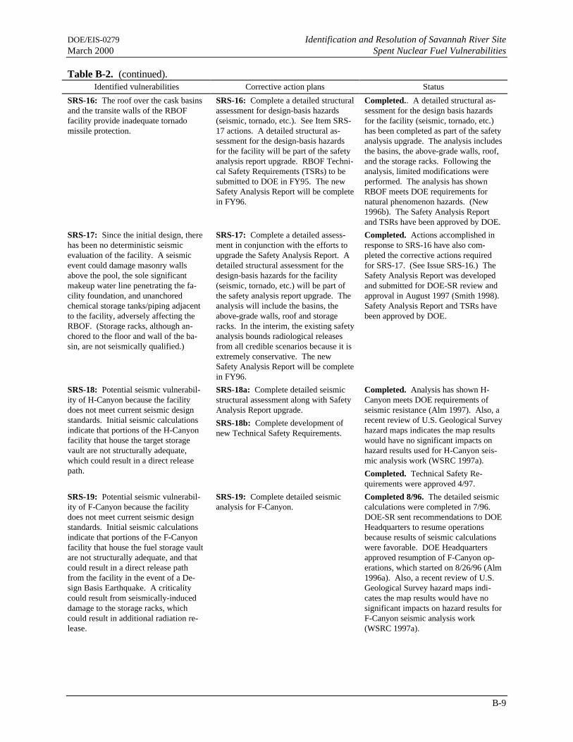
DOE/EIS-0279 Identification and Resolution of Savannah River SiteMarch 2000 Spent Nuclear Fuel Vulnerabilities
B-9
Table B-2. (continued).Identified vulnerabilities Corrective action plans Status
SRS-16: The roof over the cask basinsand the transite walls of the RBOFfacility provide inadequate tornadomissile protection.
SRS-16: Complete a detailed structuralassessment for design-basis hazards(seismic, tornado, etc.). See Item SRS-17 actions. A detailed structural as-sessment for the design-basis hazardsfor the facility will be part of the safetyanalysis report upgrade. RBOF Techni-cal Safety Requirements (TSRs) to besubmitted to DOE in FY95. The newSafety Analysis Report will be completein FY96.
Completed.. A detailed structural as-sessment for the design basis hazardsfor the facility (seismic, tornado, etc.)has been completed as part of the safetyanalysis upgrade. The analysis includesthe basins, the above-grade walls, roof,and the storage racks. Following theanalysis, limited modifications wereperformed. The analysis has shownRBOF meets DOE requirements fornatural phenomenon hazards. (New1996b). The Safety Analysis Reportand TSRs have been approved by DOE.
SRS-17: Since the initial design, therehas been no deterministic seismicevaluation of the facility. A seismicevent could damage masonry wallsabove the pool, the sole significantmakeup water line penetrating the fa-cility foundation, and unanchoredchemical storage tanks/piping adjacentto the facility, adversely affecting theRBOF. (Storage racks, although an-chored to the floor and wall of the ba-sin, are not seismically qualified.)
SRS-17: Complete a detailed assess-ment in conjunction with the efforts toupgrade the Safety Analysis Report. Adetailed structural assessment for thedesign-basis hazards for the facility(seismic, tornado, etc.) will be part ofthe safety analysis report upgrade. Theanalysis will include the basins, theabove-grade walls, roof and storageracks. In the interim, the existing safetyanalysis bounds radiological releasesfrom all credible scenarios because it isextremely conservative. The newSafety Analysis Report will be completein FY96.
Completed. Actions accomplished inresponse to SRS-16 have also com-pleted the corrective actions requiredfor SRS-17. (See Issue SRS-16.) TheSafety Analysis Report was developedand submitted for DOE-SR review andapproval in August 1997 (Smith 1998).Safety Analysis Report and TSRs havebeen approved by DOE.
SRS-18: Potential seismic vulnerabil-ity of H-Canyon because the facilitydoes not meet current seismic designstandards. Initial seismic calculationsindicate that portions of the H-Canyonfacility that house the target storagevault are not structurally adequate,which could result in a direct releasepath.
SRS-18a: Complete detailed seismicstructural assessment along with SafetyAnalysis Report upgrade.
SRS-18b: Complete development ofnew Technical Safety Requirements.
Completed. Analysis has shown H-Canyon meets DOE requirements ofseismic resistance (Alm 1997). Also, arecent review of U.S. Geological Surveyhazard maps indicates the map resultswould have no significant impacts onhazard results used for H-Canyon seis-mic analysis work (WSRC 1997a).
Completed. Technical Safety Re-quirements were approved 4/97.
SRS-19: Potential seismic vulnerabil-ity of F-Canyon because the facilitydoes not meet current seismic designstandards. Initial seismic calculationsindicate that portions of the F-Canyonfacility that house the fuel storage vaultare not structurally adequate, and thatcould result in a direct release pathfrom the facility in the event of a De-sign Basis Earthquake. A criticalitycould result from seismically-induceddamage to the storage racks, whichcould result in additional radiation re-lease.
SRS-19: Complete detailed seismicanalysis for F-Canyon.
Completed 8/96. The detailed seismiccalculations were completed in 7/96.DOE-SR sent recommendations to DOEHeadquarters to resume operationsbecause results of seismic calculationswere favorable. DOE Headquartersapproved resumption of F-Canyon op-erations, which started on 8/26/96 (Alm1996a). Also, a recent review of U.S.Geological Survey hazard maps indi-cates the map results would have nosignificant impacts on hazard results forF-Canyon seismic analysis work(WSRC 1997a).
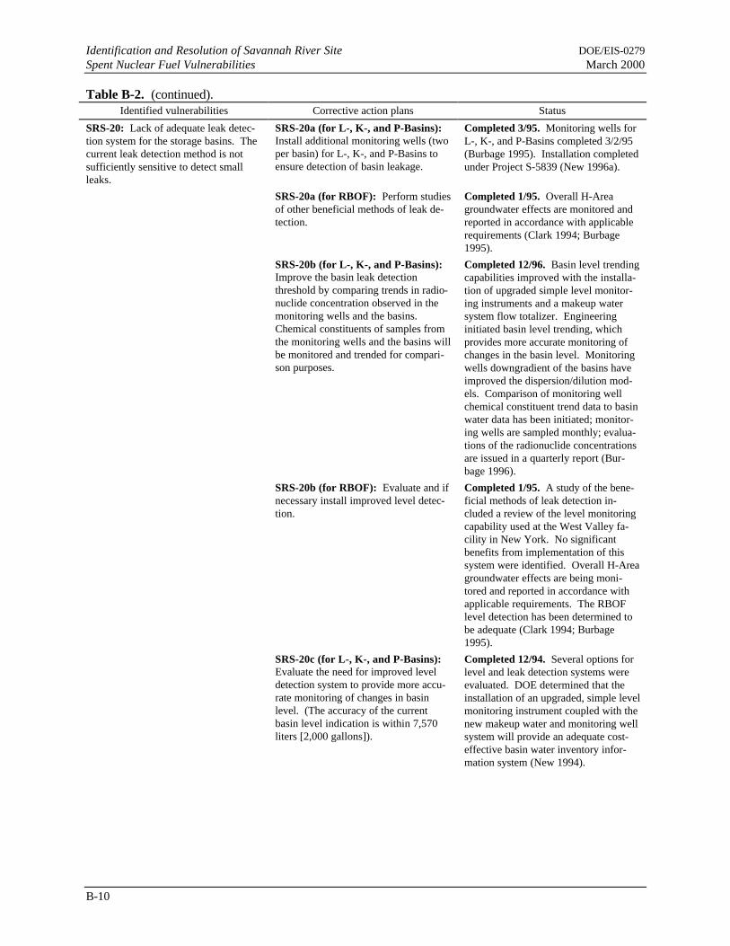
Identification and Resolution of Savannah River Site DOE/EIS-0279Spent Nuclear Fuel Vulnerabilities March 2000
B-10
Table B-2. (continued).Identified vulnerabilities Corrective action plans Status
SRS-20: Lack of adequate leak detec-tion system for the storage basins. Thecurrent leak detection method is notsufficiently sensitive to detect smallleaks.
SRS-20a (for L-, K-, and P-Basins):Install additional monitoring wells (twoper basin) for L-, K-, and P-Basins toensure detection of basin leakage.
Completed 3/95. Monitoring wells forL-, K-, and P-Basins completed 3/2/95(Burbage 1995). Installation completedunder Project S-5839 (New 1996a).
SRS-20a (for RBOF): Perform studiesof other beneficial methods of leak de-tection.
Completed 1/95. Overall H-Areagroundwater effects are monitored andreported in accordance with applicablerequirements (Clark 1994; Burbage1995).
SRS-20b (for L-, K-, and P-Basins):Improve the basin leak detectionthreshold by comparing trends in radio-nuclide concentration observed in themonitoring wells and the basins.Chemical constituents of samples fromthe monitoring wells and the basins willbe monitored and trended for compari-son purposes.
Completed 12/96. Basin level trendingcapabilities improved with the installa-tion of upgraded simple level monitor-ing instruments and a makeup watersystem flow totalizer. Engineeringinitiated basin level trending, whichprovides more accurate monitoring ofchanges in the basin level. Monitoringwells downgradient of the basins haveimproved the dispersion/dilution mod-els. Comparison of monitoring wellchemical constituent trend data to basinwater data has been initiated; monitor-ing wells are sampled monthly; evalua-tions of the radionuclide concentrationsare issued in a quarterly report (Bur-bage 1996).
SRS-20b (for RBOF): Evaluate and ifnecessary install improved level detec-tion.
Completed 1/95. A study of the bene-ficial methods of leak detection in-cluded a review of the level monitoringcapability used at the West Valley fa-cility in New York. No significantbenefits from implementation of thissystem were identified. Overall H-Areagroundwater effects are being moni-tored and reported in accordance withapplicable requirements. The RBOFlevel detection has been determined tobe adequate (Clark 1994; Burbage1995).
SRS-20c (for L-, K-, and P-Basins):Evaluate the need for improved leveldetection system to provide more accu-rate monitoring of changes in basinlevel. (The accuracy of the currentbasin level indication is within 7,570liters [2,000 gallons]).
Completed 12/94. Several options forlevel and leak detection systems wereevaluated. DOE determined that theinstallation of an upgraded, simple levelmonitoring instrument coupled with thenew makeup water and monitoring wellsystem will provide an adequate cost-effective basin water inventory infor-mation system (New 1994).

DOE/EIS-0279 Identification and Resolution of Savannah River SiteMarch 2000 Spent Nuclear Fuel Vulnerabilities
B-11
Table B-2. (continued).Identified vulnerabilities Corrective action plans Status
SRS-21: Inadequate seismic evaluationand potential inadequacies of structures,systems, and components to withstand aDesign-Basis Event. The potentialexists for: the failure of basin expansionjoints and water stops, causing a releaseof radioactive materials to the environ-ment; the failure of vertical tube storageframes or a load drop onto fuel assem-blies causing damage or reconfigurationof fuel and possible criticality, due to aseismic event. (generic issue)
SRS-21a: Complete soil stability as-sessment for input to seismic analysesfor L-, K-, and P-Basin that is in prog-ress.
SRS-21b: Complete seismic evalua-tions if determined to be necessary as aresult of the Basis for Interim Opera-tions development, or soil stability as-sessments for L-, K-, and P-Basin. Arecent assessment of the K-Basin exte-rior walls and foundations determinedthey could withstand a 0.2g earthquake.Minor leakage could occur but would beslow. A recent assessment determinedthat the consequences of an earthquakefor L- and P- Basins are less than thosefor K-Basin because K-Basin has thehighest radionuclide inventory.
Completed 10/94. Soil stability as-sessments for K- and P-Basins are notrequired (Burke 1994). Geotechnicalinvestigation into L-Areas is ongoing.
Completed 3/95. Soil stability assess-ments for K-, L-, and P-Basins are notrequired (Burke 1994). These assess-ments support seismic analyses ofemergency cooling systems; however,the BIO (WSRC 1995c) determined thatfuels stored in the basins do not requireemergency cooling after a postulatedDesign-Basis Event resulting in basindraindown.
SRS-21c: Depending on results of BIOcompleted by 11/94, development ofaccident mitigation procedures might beappropriate.
Completed 7/96. Accident mitigationprocedures are not required because thisaccident would result in low conse-quences.
SRS-21d: See Item 5,7,9a for reorien-tation of fuel.
Completed 7/97.
SRS-22: Potential vulnerability inburied fuel at SRS.
SRS-22: Fuel failure of a Mark V fuelassembly occurred in the R-Area disas-sembly basin in 1957. Over 7 years, thefissile materials in the failed fuel as-sembly completely oxidized. In 1964,the remains of the assembly were re-trieved with no appreciable amount offuel or fission products remaining in theassembly. All of the oxidized fuel nearthe assembly was removed using filtersand deionizers and subsequently proc-essed in RBOF. The fuel material iscurrently held in authorized basins andtanks. No further action is required.
Completed 12/93.

Identification and Resolution of Savannah River Site DOE/EIS-0279Spent Nuclear Fuel Vulnerabilities March 2000
B-12
NOTE: This item was discussed in theSpent Fuel Working Group Reportsummary but not addressed in vulner-ability development forms.
Disassembly basins do not have highefficiency (confinement/negative pres-sure) ventilation systems.
NOTE: The K-Area Basis for InterimOperation addresses the existing facilityand safety margins with respect to theneed for airborne release containment.The results of the BIO show there isadequate safety margin without facilityupgrades. Upgrades are not requiredfor several reasons:- Over 40 years of operating experi-
ence with no events involving thespread of particulate radioactivecontamination from the basins.
- Little stored energy in the disassem-bly basins because of radioactivedecay.
- Radiation level in the disassemblybasin area is low (<2 millirem/hour)and the contribution from airborneparticulate matter is negligible.
Completed 3/95. Area BIO was ap-proved by DOE; no further action isrequired (WSRC 1995c).
DNFSB 94-1 addressed vulnerabilities at severalDOE sites, including the following SRS vulner-abilities concerning SNF and related solutions,tanks, and processing activities:
Several large tanks in the F-Canyon at the Sa-vannah River Site contain tens of thousands ofgallons of solutions of plutonium and transplu-tonium isotopes. These tanks, their append-ages, and vital support systems are old, subjectto deterioration, prone to leakage, and they arenot seismically qualified.
Processing canyons and reactor basins at theSavannah River Site contain large amounts ofdeteriorating irradiated reactor fuel stored un-der conditions similar to those at the 603 Basinat INEL [Idaho National Engineering Labora-tory].
There are thousands of containers of pluto-nium-bearing liquids and solids at ... SRS ....Large quantities of plutonium solutions arestored in deteriorating tanks, piping, and plasticbottles.... It is well known that plutonium incontact with plastic can cause formation of hy-drogen gas and pyrophoric plutonium com-pounds leading to a high probability ofplutonium fires.
The slow pace of remediation and additionaldelays in stabilizing materials might be accom-panied by further deterioration of safety andunnecessary increased risks to workers and thepublic.
DOE accepted the Board’s Recommendation onAugust 31, 1994, and issued The Defense Nu-clear Facilities Safety Board Recommendation94-1 Implementation Plan (DOE 1995b). Ta-ble B-3 summarizes the SRS vulnerabilitiesidentified in DNFSB 94-1 and the associatedcommitments made by DOE in the Implementa-tion Plan.
B.5 DNFSB January 1995 SRSSpent Fuel Vulnerability Assess-ment
In January 1995, members of the DNFSB staffassessed SRS progress toward resolving vulner-abilities associated with the storage of spent fuel.Their SRS Spent Fuel Storage Trip Report,January 23, 1995 (Burnfield 1995) stated thatalthough DOE Headquarters had agreed to ap-proach spent fuel vulnerability problems using asystems approach, they had been slow in imple-menting that approach and there was little evi-dence of SRS applying the approach to the spentfuel management project.
DNFSB members expressed concern that aggres-sive action was not being taken to resolve vulner-abilities related to improving the water chemistryof the basins. They also highlighted two newareas of concern related to RBOF.
The report acknowledged that Westinghouse Sa-vannah River Company had initiated an aggres-
DOE/EIS-0279 Identification and Resolution of Savannah River SiteMarch 2000 Spent Nuclear Fuel Vulnerabilities
B-13
sive program to ensure that the risks associatedwith these two new areas of concern were accu-rately quantified and were acceptable. However,the efforts for the two areas were not tied to-gether and therefore could result in an inability tolink the two hazards successfully.
The DNFSB did not formally submit these issuesand the trip report to DOE. As a consequence,formal corrective actions were not developed nor
were these issues entered into and tracked by theDOE Safety Issues Management System. How-ever, Westinghouse Savannah River Companyperformed two nuclear criticality safety evalua-tions to address these issues: Reactivity Effects ofTilting Fuel Assemblies and Bundles in RBOF(Reed 1995) and Credible Water Depth forCriticality Incidents
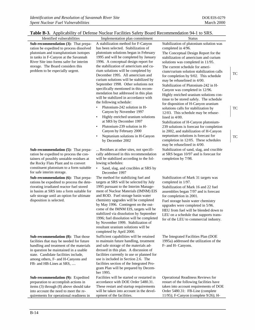
Identification and Resolution of Savannah River Site DOE/EIS-0279Spent Nuclear Fuel Vulnerabilities March 2000
B-14
Table B-3. Applicability of Defense Nuclear Facilities Safety Board Recommendation 94-1 to SRS.Identified vulnerabilities Implementation plan commitment Status
Sub-recommendation (3): That prepa-ration be expedited to process dissolvedplutonium and transplutonium isotopesin tanks in F-Canyon at the SavannahRiver Site into forms safer for interimstorage. The Board considers thisproblem to be especially urgent.
A stabilization method for F-Canyonhas been selected. Stabilization ofplutonium solutions began in February1995 and will be completed by January1996. A conceptual design report forthe stabilization of americium and cu-rium solutions will be completed byDecember 1995. All americium andcurium solutions will be stabilized bySeptember 1998. Other solutions notspecifically mentioned in this recom-mendation but addressed in this planwill be stabilized in accordance withthe following schedule:• Plutonium-242 solution in H-
Canyon by November 1997• Highly enriched uranium solutions
at SRS by December 1997• Plutonium-239 solution in H-
Canyon by February 2000• Neptunium solutions in H-Canyon
by December 2002
Stabilization of plutonium solution wascompleted in 4/96.The Conceptual Design Report for thestabilization of americium and curiumsolutions was completed in 11/95.The current schedule for ameri-cium/curium solution stabilization callsfor completion by 9/02. This schedulemay be rebaselined in 4/00.Stabilization of Plutonium-242 in H-Canyon was completed in 12/96.Highly enriched uranium solutions con-tinue to be stored safely. The schedulefor disposition of H-Canyon uraniumsolutions calls for stabilization by12/03. This schedule may be rebase-lined in 4/00.Stabilization of H-Canyon plutonium-239 solutions is forecast for completionin 2002, and stabilization of H-Canyonneptunium solutions is forecast forcompletion in 12/05. These schedulesmay be rebaselined in 4/00.
Sub-recommendation (5): That prepa-ration be expedited to process the con-tainers of possibly unstable residues atthe Rocky Flats Plant and to convertconstituent plutonium to a form suitablefor safe interim storage.
... Residues at other sites, not specifi-cally addressed in this recommendationwill be stabilized according to the fol-lowing schedules:• Sand, slag, and crucibles at SRS by
December 1997
Stabilization of sand, slag, and crucibleat SRS began 10/97 and is forecast forcompletion by 7/98.
Sub-recommendation (6): That prepa-rations be expedited to process the dete-riorating irradiated reactor fuel storedin basins at SRS into a form suitable forsafe storage until an option for ultimatedisposition is selected.
The method for stabilizing fuel andtargets at SRS will be selected by July1995 pursuant to the Interim Manage-ment of Nuclear Materials (IMNM) EISand ROD. Fuel storage basin waterchemistry upgrades will be completedby May 1996. Contingent on the out-come of the IMNM EIS, targets will bestabilized via dissolution by September1996; fuel dissolution will be completedby November 1999. Stabilization ofresultant uranium solutions will becompleted by April 2000.
Stabilization of Mark 31 targets wascompleted in 1/97.Stabilization of Mark 16 and 22 fuelassemblies began 7/97 and is forecastfor completion in 2001.Fuel storage basin water chemistryupgrades were completed in 5/96.HEU from fuel will be blended down toLEU on a schedule that supports trans-fer of the LEU to commercial industry.
Sub-recommendation (8): That thosefacilities that may be needed for futurehandling and treatment of the materialsin question be maintained in a usablestate. Candidate facilities include,among others, F- and H-Canyons andFB- and HB-Lines at SRS, ....
Sufficient capabilities will be retainedto maintain future handling, treatmentand safe storage of the materials ad-dressed in this plan. A discussion offacilities currently in use or planned foruse is included in Section 2.6. Thefacilities section of the Integrated Pro-gram Plan will be prepared by Decem-ber 1995.
The Integrated Facilities Plan (DOE1995a) addressed the utilization of theF- and H- Canyons.
Sub-recommendation (9): Expeditedpreparation to accomplish actions initems (3) through (8) above should takeinto account the need to meet the re-quirements for operational readiness in
Facilities will be started or restarted inaccordance with DOE Order 5480.31.These restart and startup requirementswill be taken into account in the devel-opment of the facilities.
Operational Readiness Reviews forrestart of the following facilities havetaken into account requirements of DOEOrder 5480.31: FB-Line (complete11/95); F-Canyon (complete 9/26); H-
TC
TC
TC

DOE/EIS-0279 Identification and Resolution of Savannah River SiteMarch 2000 Spent Nuclear Fuel Vulnerabilities
B-15
accordance with DOE Order 5480.31. Canyon Dissolving (complete 7/97); HB-Line Dissolving (complete 3/98)
in RBOF (Reed 1996). Table B-4 summarizesthe SRS vulnerabilities identified in the trip re-port and results of the safety evaluations.
B.6 DNFSB June 1995 SRS SpentFuel Vulnerability Assessment
In June 1995, members of the DNFSB visited theSRS to review SNF activities related to the im-plementation of DNFSB Recommendation 94-1(see Section B.4). The DNFSB Chairman for-mally transmitted the report to DOE and identi-fied issues that were “... not being adequatelyconsidered in the evaluation of remediation alter-natives.” In addition, the report identified badlycorroding foreign fuel in RBOF that DOE hadcategorized as stable (Conway 1995).
The corroding foreign fuel that DOE had catego-rized as stable was failed Taiwanese ResearchReactor Fuel and Experimental Breeder Reactorslugs that were being stored in cans in RBOF.Although the damaged fuel was housed in pro-tective cans, the cans were leaking and continueddeterioration was likely. DOE responded to this
concern by issuing the Interim Management ofNuclear Material EIS Record of Decision (60 FR65300), which identified chemical processing asthe preferred alternative for the at-risk foreignfuel.
In the Draft Environmental Impact Statement,Interim Management of Nuclear Materials(DOE 1995c), DOE identified Processing toMetal as the preferred alternative for the reme-diation of Mark-16 and -22 fuels. DNFSB be-came aware that DOE was considering drystorage of aluminum-clad fuel as an alternative tochemical processing. DOE issued the FinalIMNM EIS (DOE 1995d) with No Action as thepreferred alternative for these fuels to allow timefor further consideration of dry storage. DNFSBexpressed three specific concerns on the stabili-zation technologies for Mark-16 and -22 fuel.DOE’s final decision was to identify ChemicalProcessing as the preferred alternative for thismaterial, as recorded in the second IMNM Rec-ord of Decision (61 FR 6633).
Table B-5 summarizes the SRS vulnerabilitiesidentified in the trip report.
Table B-4. Vulnerabilities identified in the January 1995 Defense Nuclear Facilities Safety Board TripReport.
Identified vulnerabilities Implementation plan commitment Status
Some fuel in RBOF is stored verticallyin racks, allowing the fuel to lean fromtop to bottom slightly, resulting in aviolation of criticality safety require-ments.
The DNFSB did not choose to submitthese issues and this trip report formallyto DOE. Consequently, formal correc-tive actions were not developed norwere these issues entered into andtracked by the DOE Safety Issues Man-agement System.
Calculations documented in NuclearCriticality Safety Evaluation: Reactiv-ity Effects of Tilting Fuel Assembliesand Bundles in RBOF (Reed 1995)resulted in the conclusion that, “Thereare no current situations in RBOF Stor-age Basin #1 in which the configurationhas been determined to be more reac-tive than a keff of 0.95, the TechnicalStandard limit.”
The amount of water shielding wasmisidentified in the safety documenta-tion.
The DNFSB did not choose to submitthese issues and this trip report formallyto DOE. Consequently, formal correc-tive actions were not developed norwere these issues entered into andtracked by the DOE Safety Issues Man-agement System.
An analysis documented in NuclearCriticality Safety Evaluation: CredibleWater Depth for Criticality Incidents inRBOF (Reed 1996), concluded that,“Thus, there is no basis to define a NIMevacuation zone (region in which per-sonnel can receive 12 rads or more as aresult of a criticality incident) for theRBOF basins. Based on requirementsof DOE Order 5480.24, a criticality
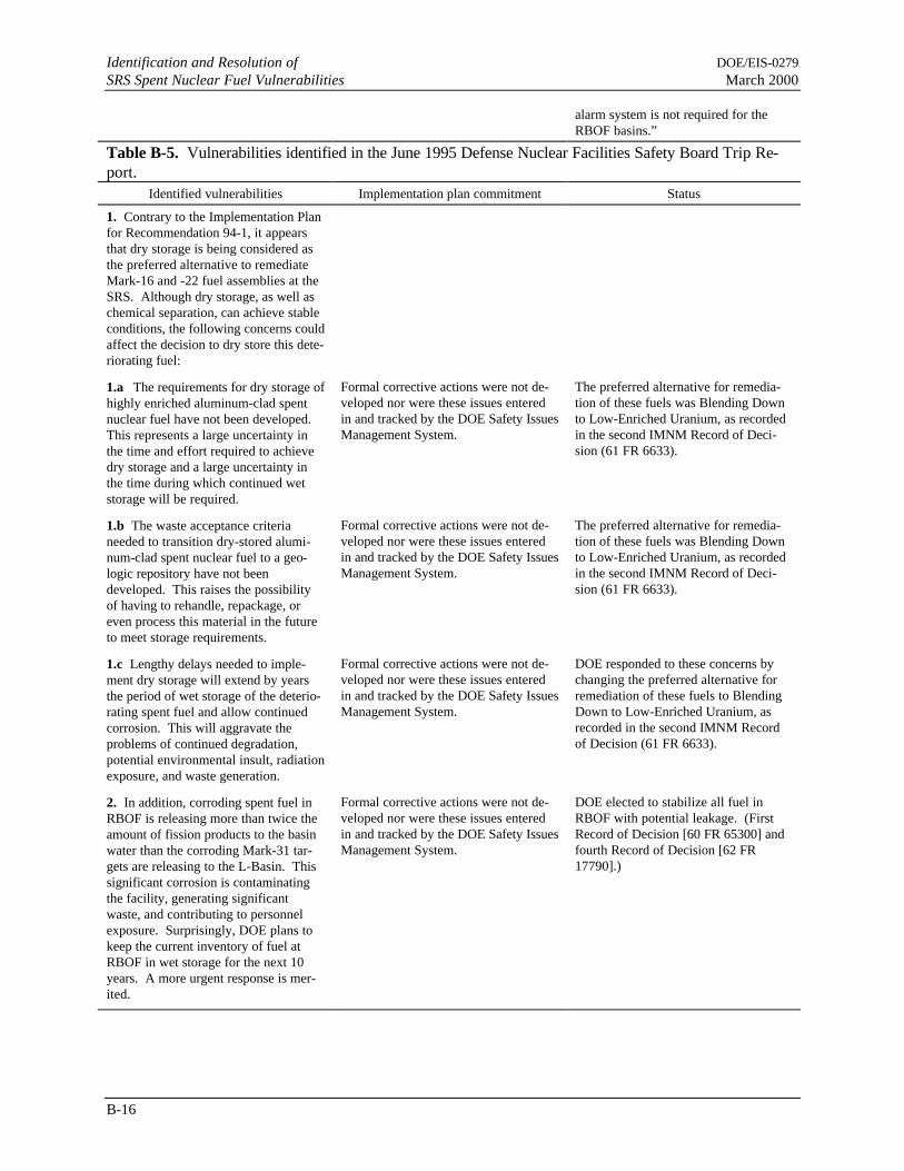
Identification and Resolution of DOE/EIS-0279SRS Spent Nuclear Fuel Vulnerabilities March 2000
B-16
alarm system is not required for theRBOF basins.”
Table B-5. Vulnerabilities identified in the June 1995 Defense Nuclear Facilities Safety Board Trip Re-port.
Identified vulnerabilities Implementation plan commitment Status
1. Contrary to the Implementation Planfor Recommendation 94-1, it appearsthat dry storage is being considered asthe preferred alternative to remediateMark-16 and -22 fuel assemblies at theSRS. Although dry storage, as well aschemical separation, can achieve stableconditions, the following concerns couldaffect the decision to dry store this dete-riorating fuel:
1.a The requirements for dry storage ofhighly enriched aluminum-clad spentnuclear fuel have not been developed.This represents a large uncertainty inthe time and effort required to achievedry storage and a large uncertainty inthe time during which continued wetstorage will be required.
Formal corrective actions were not de-veloped nor were these issues enteredin and tracked by the DOE Safety IssuesManagement System.
The preferred alternative for remedia-tion of these fuels was Blending Downto Low-Enriched Uranium, as recordedin the second IMNM Record of Deci-sion (61 FR 6633).
1.b The waste acceptance criterianeeded to transition dry-stored alumi-num-clad spent nuclear fuel to a geo-logic repository have not beendeveloped. This raises the possibilityof having to rehandle, repackage, oreven process this material in the futureto meet storage requirements.
Formal corrective actions were not de-veloped nor were these issues enteredin and tracked by the DOE Safety IssuesManagement System.
The preferred alternative for remedia-tion of these fuels was Blending Downto Low-Enriched Uranium, as recordedin the second IMNM Record of Deci-sion (61 FR 6633).
1.c Lengthy delays needed to imple-ment dry storage will extend by yearsthe period of wet storage of the deterio-rating spent fuel and allow continuedcorrosion. This will aggravate theproblems of continued degradation,potential environmental insult, radiationexposure, and waste generation.
Formal corrective actions were not de-veloped nor were these issues enteredin and tracked by the DOE Safety IssuesManagement System.
DOE responded to these concerns bychanging the preferred alternative forremediation of these fuels to BlendingDown to Low-Enriched Uranium, asrecorded in the second IMNM Recordof Decision (61 FR 6633).
2. In addition, corroding spent fuel inRBOF is releasing more than twice theamount of fission products to the basinwater than the corroding Mark-31 tar-gets are releasing to the L-Basin. Thissignificant corrosion is contaminatingthe facility, generating significantwaste, and contributing to personnelexposure. Surprisingly, DOE plans tokeep the current inventory of fuel atRBOF in wet storage for the next 10years. A more urgent response is mer-ited.
Formal corrective actions were not de-veloped nor were these issues enteredin and tracked by the DOE Safety IssuesManagement System.
DOE elected to stabilize all fuel inRBOF with potential leakage. (FirstRecord of Decision [60 FR 65300] andfourth Record of Decision [62 FR17790].)

DOE/EIS-0279 Identification and Resolution of Savannah River SiteMarch 2000 Spent Nuclear Fuel Vulnerabilities
B-17
B.7 DNFSB 1996 SRS Spent FuelHandling Assessment
In August 1996, members of the DNFSB as-sessed SRS spent fuel handling and processingoperations. The Board noted that the transfer ofspent fuel requires moving massive casks in spentfuel storage basins where a cask drop couldcause structural damage and significant waterinventory loss. Their Trip Report (Conway1996) reported the following concerns associatedwith stabilization operations and the retrieval ofspent fuel from the K, L, and P Basins:
1. There is no assurance that makeup water willbe available after a design-basis accident.
2. The crane rope is corroded, and the fatiguelife of some cranes is not known.
3. A qualified rigger is not present during criti-cal cask lifts.
4. Although fuel is being removed from the ba-sins, significant quantities of activated scrapmetal will remain.
DOE first responded to these concerns in a letterto the Board dated November 21, 1996 (Alm1996b). DOE provided a more detailed responsein a letter dated December 13, 1996 (Alm1996c). Table B-6 summarizes the SRS SNFtransfer vulnerabilities identified in the 1996 TripReport and the associated DOE responses andcommitments (Potvin 1997).

Identification and Resolution of DOE/EIS-0279SRS Spent Nuclear Fuel Vulnerabilities March 2000
B-18
Table B-6. Vulnerabilities identified in the August 1996 Defense Nuclear Facilities Safety Board TripReport.
Identified vulnerabilities Implementation plan commitment Status
There is no assurance that makeup wa-ter will be available if a cask drop orseismic event should cause a leak.Basin water is supposed to be replacedby raw untreated water from the Emer-gency Service Water system; however,this line is not tested regularly, it hasnot been used for more than a year, andit is not seismically qualified.
Studies indicate that dropping the 63.5 metric-ton (70-ton) cask, as analyzed in the recentlyissued Basis for Interim Operation for L-Reactor, could potentially result in a crack witha maximum leak of 397 liters (105 gallons) perminute. At this rate, operators would have aminimum of 6 days to implement mitigativeactions before radiation levels began to in-crease, at which point all workers in the vicin-ity would be evacuated. In such an event,operators could respond by implementing vari-ous procedures using available systems to re-store basin water levels.
Although detailed preplanned and demon-strated emergency capabilities are not requiredfor accident scenarios that would allow ade-quate time for facility workers to respond, anintegrated facility response to a basin leak isbeing developed. This response, to be com-pleted in the second quarter of FY 97, willconsist of a combination of operational proce-dures and engineering response plans with theobjective of mitigating basin leakage.
A letter to the DOE-SR DNFSBLiaison (Voss 1997a) identifiedplans and procedures developedin response to this vulnerability.
A qualified rigger is not present duringfuel cask lifts. Fuel cask lifts are criti-cal and preengineered. However, acrane operator, who has only IncidentalRigger Training, performs both therigging and crane movement. Thisseems to contradict the SRS Hoistingand Rigging Manual, which states that arigger shall ensure (1) the riggingequipment has the required capacityand is in good condition, (2) the riggingequipment is per procedure, and (3) theload path is clear.
Preengineered lifts are established for routine,repetitive lifting jobs such as cask movement.For these lifts, established procedures definethe rigging equipment and the process used.These cask-handling procedures are reviewedby fully qualified Site rigging personnel.
Facility operators attend “incidental rigger/operator” training. The “incidental rigger” istrained to ensure the rigging equipment has therequired capacity and is in good condition, therigging equipment is utilized per procedures,and the load path is clear. These qualificationsare appropriate for the routine preengineeredoperations conducted in the facility.
This commitment is complete(WSRC 1997b).
Corrosion is evident along the entirelength of the K-Basin cask crane’s wirerope and the fatigue life of basin cranesis not known. DNFSB staff were notable to view the L-Basin crane rope, butwere told its condition is similar.ASME B30.2-1990 identifies excessivecorrosion on wire rope as a hazard.WSRC stated that the rope is adequatebased on visual inspection by site rig-gers. However, as noted in the Con-struction Safety Association ofOntario’s Rigging Manual, visual in-spection gives a poor indication of theextent of degradation since corrosionoften begins inside the rope. A morerigorous inspection includes examining
SRS has a comprehensive crane inspectionprogram, which is based on a compilation ofvarious national and international codes andstandards. The quarterly and annual craneinspections are performed in accordance withOverhead and Gantry Cranes, ASME B30.2,Chapter 2-2. The wire ropes are inspected ona monthly frequency pursuant to “Overheadand Gantry Cranes,” 29 CFR 1910.179(m), andinspection criteria in accordance with ASMEB30.2, Section 2-2.4.
Crane inspection program documents for theK- and L-Basins and the Receiving Basin forOffsite Fuel to be provided to the DNFSB willdescribe inspection requirements, frequencyand criteria, load tests, dye-penetrant tests, etc.
DOE responded to this as docu-mented in a letter (Sidey 1997).On January 20, 1997, additionalreferences were provided in re-sponse to Commitment 2 (Voss1997b).

DOE/EIS-0279 Identification and Resolution of Savannah River SiteMarch 2000 Spent Nuclear Fuel Vulnerabilities
B-19
the rope

Identification and Resolution of DOE/EIS-0279SRS Spent Nuclear Fuel Vulnerabilities March 2000
B-20
Table B-6. (continued).Identified vulnerabilities Implementation plan commitment Status
core. If the core is corroded, the cranes’safety factor may be much less thanWSRC believes.
As part of scoping stage for determining theneed for a crane upgrade proposal for DOE, arepresentative from the crane manufacturerwill perform a baseline inspection/evaluationof the 11-metric-ton (85-ton) crane and issue areport.
All documentation will be transmitted within60 days of the crane manufacturer’s inspection.
Although fuel is being removed fromthe basins, significant quantities ofactivated scrap metal will remain. Be-sides fuel, the basins store buckets ofhighly radioactive scrap metal. Thesebuckets are suspended by rope and cor-roding wire cables. In contrast with thefuel, no plan of action has been formu-lated for retrieval of this material.
As part of efforts to enhance water quality andreduce hazards, WSRC has been pursuingremoval of selected materials from the basins.Activities to date have focused on removal ofthe more serious hazards, including cadmiumcontrol rods, corroded fuel, and excess radio-active sources. Future efforts will be directedat the remaining materials such as irradiatedmetal and contaminated scrap.
DOE has recently improved methods for dis-posing of waste at SRS. These are part of awaste certification program that ensures theidentification of characteristics of all wastes toenable proper disposal. The RBOF WasteCertification Plan is in revision and will reflectthe new waste disposal process. Implementa-tion schedules will be based on resource andbudget availability.
After discussions with DOE, itwas determined that no deliver-able was required to be forwardedto DNFSB concerning this issue.

DOE/EIS-0279 Identification and Resolution of Savannah River SiteMarch 2000 Spent Nuclear Fuel Vulnerabilities
B-21
References
Alm, A. L., 1996a, “F-Canyon Nuclear Material Stabilization Activities,” internal memorandum toM. J. Fiori, U.S. Department of Energy, Washington, D.C., August 20.
Alm, A. L., 1996b, Letter to John T. Conway, (Chairman, Defense Nuclear Facilities Safety Board),U.S. Department of Energy, Washington, D.C., November 21.
Alm, A. L., 1996c, Letter to John T. Conway, (Chairman, Defense Nuclear Facilities Safety Board),U.S. Department of Energy, Washington, D.C., December 13.
Alm, A. L., 1997, “H-Canyon Seismic Issue and Nuclear Material Stabilization Activities,” internalmemorandum to M. J. Fiori, U.S. Department of Energy, Washington, D.C., January 27.
Burbage, G. L., 1995, “Leak Detection at the Receiving Basin for Offsite Fuels by GroundwaterMonitoring,” interoffice memorandum, Westinghouse Savannah River Company, Savannah River Site,Aiken, South Carolina, January 10.
Burbage, G. L., 1996, October 1996 Disassembly Basin Monitoring Data Summary (U), SFS-RPS-960028, Westinghouse Savannah River Company, Savannah River Site, Aiken, South Carolina.
Burke, S. D., 1993, Reactor Division Disassembly Basin Management Plan (U), RRD-RSE-93-0075,Westinghouse Savannah River Company, Savannah River Site, Aiken, South Carolina.
Burke, S. D., 1994, DOE SNF Vulnerability Assessment Action Plan Items 21a and 21b (U), RRD-RSE-940284, Westinghouse Savannah River Company, Savannah River Site, Aiken, South Carolina.
Burke, S. D., 1997, internal memorandum, “DOE Vulnerability Assessment Corrective Action PlansClosure (U),” SFS-RSE-960023, Westinghouse Savannah River Company, Savannah River Site,Aiken, South Carolina, February 21.
Burnfield, D., 1995, SRS Spent Fuel Storage Trip Report, January 3-6, 1995, Defense Nuclear FacilitiesSafety Board, Washington, D.C.
Cederdahl, B., and D. Freeman, 1994, internal memorandum, “Division Critical Item - RBOF RegenerationSystem Improvements,” Westinghouse Savannah River Company, Savannah River Site, Aiken, SouthCarolina, October 28.
Clark, B. D., 1994, Vulnerability Assessment Action Plan Closure - RBOF Item 20 (U), RRD-RSE-940259, Westinghouse Savannah River Company, Savannah River Site, Aiken, South Carolina.
Conway, J. T., 1995, Spent Nuclear Fuel at the Savannah River Site (SRS), Trip Report for June 20-21,1995, Defense Nuclear Facilities Safety Board, Washington, D.C.
Conway, J. T., 1996, Handling of Spent Nuclear Fuel at the Savannah River Site (SRS), Trip Report forAugust 5-7, 1996, Defense Nuclear Facilities Safety Board, Washington, D.C.
Conway, J. T., 1998, "Sludge Milestones," letter to F. Pena (U.S. Department of Energy), Defense NuclearFacilities Safety Board, Washington, D.C., April 15.

Identification and Resolution of DOE/EIS-0279SRS Spent Nuclear Fuel Vulnerabilities March 2000
B-22
DNFSB (Defense Nuclear Facilities Safety Board), 1994, Recommendation 94-1 (DNFSB 94-1),Improved Schedule for Remediation in the Defense Nuclear Facilities Complex, Washington, D.C.
DOE (U.S. Department of Energy), 1993, Spent Fuel Working Group Report on Inventory and Storage ofthe Department’s Spent Nuclear and other Reactor Irradiated Nuclear Material and TheirEnvironmental, Safety and Health Vulnerabilities, Volumes I, II and III, Washington, D.C.
DOE (U.S. Department of Energy), 1994a, Plan of Action to Resolve Spent Nuclear Fuel Vulnerabilities,Phase I, Washington, D.C.
DOE (U.S. Department of Energy), 1994b, Plan of Action to Resolve Spent Nuclear Fuel Vulnerabilities,Phase II, Washington, D.C.
DOE (U.S. Department of Energy), 1994c, Plan of Action to Resolve Spent Nuclear Fuel Vulnerabilities,Phase III, Revision B., Washington, D.C.
DOE (U.S. Department of Energy), 1995a, Baseline Change Proposal (BCP) for Disassembly BasinUpgrades, BCP 95-D-158/005, Savannah River Operations Office, Aiken, South Carolina.
DOE (U.S. Department of Energy), 1995b, Defense Nuclear Facilities Safety Board Recommendation 94-1 Implementation Plan, Washington, D.C.
DOE (U.S. Department of Energy), 1995c, Draft Environmental Impact Statement, Interim Managementof Nuclear Materials, DOE/EIS-0220D, Savannah River Site, Aiken, South Carolina.
DOE (U.S. Department of Energy), 1995d, Final Environmental Impact Statement, Interim Managementof Nuclear Materials, DOE/EIS-0220, Savannah River Site, Aiken, South Carolina, October.
Guy, J. C., 1993, Storage Solution for Fuel Tubes in the L-Area Vertical Tube Storage (U), RRD-RED-93-0217, Westinghouse Savannah River Company, Savannah River Site, Aiken, South Carolina.
Guy, J. C., 1995, Installation and Testing of New Horizontal Fuel Rack in L-Area Disassembly Basin(U), EFR-RSE-950124, Westinghouse Savannah River Company, Savannah River Site, Aiken, SouthCarolina.
Hochel, R. C., 1995, Evaluation of Basin Air Radiological Hazard from Fission Gases (U), SRT-ADS-95-0198, Westinghouse Savannah River Company, Savannah River Site, Aiken, South Carolina.
Holmes, W., 1995, L-3.3 Fuel Bundling (U), EFR-RSE-950188, Westinghouse Savannah River Company,Savannah River Site, Aiken, South Carolina.
Howell, J. P., 1996, Corrosion Surveillance in Spent Fuel Storage Pools (U), SRT-MTS-96-0080,Westinghouse Savannah River Company, Savannah River Site, Aiken, South Carolina.
New, I.B., 1994, Level Monitoring for the Disassembly Basins (U), RRD-940155, WestinghouseSavannah River Company, Savannah River Site, Aiken, South Carolina.
New, I. B., 1995, SNF Dry Storage Facility Procurement Technical Specifications (U), EFR-9500138,Westinghouse Savannah River Company, Savannah River Site, Aiken, South Carolina.
DOE/EIS-0279 Identification and Resolution of Savannah River SiteMarch 2000 Spent Nuclear Fuel Vulnerabilities
B-23
New, I. B., 1996a, Operational Release of Continuous Deionizer Facilities (U), EFR-960058,Westinghouse Savannah River Company, Savannah River Site, Aiken, South Carolina.
New, I. B., 1996b, Safety Analysis Report (U), EFR-960085, Westinghouse Savannah River Company,Savannah River Site, Aiken, South Carolina.
Potvin, J. C, 1997, WSRC Letter, DOE Commitment (WSRC Ref.: 97-007) RE: SRS Spent Nuclear FuelTrip Report Observations- EFR, RBOF, K-Basin, L-Basin (U), PEC-DNF-97-0022, WestinghouseSavannah River Company, Savannah River Site, Aiken, South Carolina.
Reed, R. L., 1994, 100 Area Irradiated Fuel Consolidation and Horizontal Storage Criticality Concerns(U), SRT-CMA-930074, Revision 0, Westinghouse Savannah River Company, Savannah River Site,Aiken, South Carolina.
Reed, R. L., 1995, Nuclear Criticality Safety Evaluation: Reactivity Effects of Tilting Fuel Assembliesand Bundles in RBOF (U), EPD-CTG-950026, Westinghouse Savannah River Company, SavannahRiver Site, Aiken, South Carolina.
Reed, R. L., 1996, Nuclear Criticality Safety Evaluation: Credible Water Depth for Criticality Incidentsin RBOF (U), N-NCS-H-00011, Westinghouse Savannah River Company, Savannah River Site,Aiken, South Carolina.
Sidey, K., 1997, “Commitment #2, Re: SRS Spent Nuclear Fuel Trip Report Observations- EFR, RBOF,K-Basin, L-Basin,” letter to A. Poston, U.S. Department of Energy, Savannah River OperationsOffice, Aiken, South Carolina, January 16.
Sindelar, R. L., H. B. Peacock, Jr., P. S. Lam, N. C. Iyer, and M. R. Louthan, Jr., 1996, AcceptanceCriteria for Interim Dry Storage of Aluminum-Alloy Clad Spent Nuclear Fuels (U), WSRC-TR-95-0347, Westinghouse Savannah River Company, Savannah River Site, Aiken, South Carolina.
Smith, P. K., 1998, DOE Vulnerability Assessment Corrective Action Plan Status (U), SFS-RSE-98-0081, Westinghouse Savannah River Company, Savannah River Site, Aiken, South Carolina.
Voss, T. J., 1997a, “SRS Spent Nuclear Fuel Trip Report Observations-SFS, RBOF, K-Basin, L-Basin(U),” PEC-DNF-97-0062, letter to A. Poston, U.S. Department of Energy, Westinghouse SavannahRiver Company, Savannah River Site, Aiken, South Carolina, April 17.
Voss, T. J., 1997b, “DOE Commitment - SIMS 96-024, Commitment 001 (WSRC Ref.: 97-015) Re: SRSSpent Nuclear Fuel Trip Report Observations- EFR, RBOF, K-Basin, L-Basin (U),” PEC-DNF-97-0031, letter, Westinghouse Savannah River Company, Savannah River Site, Aiken, South Carolina,February 4.
WSRC (Westinghouse Savannah River Company), 1995a, Disassembled Component Log - Fuel BundlingStation, DPSOL 105-3800B-PLK, Savannah River Site, Aiken, South Carolina.
WSRC (Westinghouse Savannah River Company), 1995b, Disassembly Basins Upgrades, M-FPR-G-00003, Revision 3, Savannah River Site, Aiken, South Carolina.

Identification and Resolution of DOE/EIS-0279SRS Spent Nuclear Fuel Vulnerabilities March 2000
B-24
WSRC (Westinghouse Savannah River Company), 1995c, Basis for Interim Operation (BIO) forK-Reactor in Cold Standby (U), WSRC-TR-94-0207, Revision 0, Savannah River Site, Aiken, SouthCarolina.
WSRC (Westinghouse Savannah River Company), 1995d, Hazards Assessment Document for K-Reactorin Cold Standby (U), WSRC-TR-93-665, Savannah River Site, Aiken, South Carolina.
WSRC (Westinghouse Savannah River Company), 1995e, Install New Twin Hoist Yoke, Work RequestPackage No. BHBRS, Savannah River Site, Aiken, South Carolina.
WSRC (Westinghouse Savannah River Company), 1996, Basis for Interim Operation for the L-ReactorFacility (U), WSRC-TR-95-0054, Savannah River Site, Aiken, South Carolina.
WSRC (Westinghouse Savannah River Company), 1997a, SRS Seismic Response Analysis Design BasisGuidelines, WSRC-TR-97-0085, Revision 0, Savannah River Site, Aiken, South Carolina.
WSRC (Westinghouse Savannah River Company), 1997b, Spent Fuel Storage Division FacilityAssessment Checklist, Basin Operations and Fuel Shipment, Revision 3, Savannah River Site, Aiken,South Carolina.
DOE/EIS-0279 Identification and Resolution of Savannah River SiteMarch 2000 Spent Nuclear Fuel Vulnerabilities
B-25
accident, 7, 10, 15, 16Accident, 10canyons, 11criticality, 4, 5, 7, 8, 10, 11, 13Defense Nuclear Facilities Safety Board, 1, 2,
11, 12, 13, 14, 16,DOE, 1, 2, 3, 5, 6, 7, 8, 9, 10, 11, 12, 13, 14,
15, 16, 17,FB-Line, 12geologic repository, 14groundwater, 9Group A, 2HB-Line, 12HEU, 12impacts, 6, 8
LEU, 12L-Reactor Disassembly Basin, 3plutonium, 1, 11, 12preferred alternative, 13, 14process, 12, 14, 16, 17Receiving Basin for Offsite Fuel, 2, 16Recommendation 94-1, 2, 11, 12, 13, 14processing, 1Savannah River Site,1, 4, 11, 12,separations, 1U.S. Department of Energy, 1,uranium, 6, 12waste acceptance criteria, 14waste generation, 14

APPENDIX C
SPENT NUCLEAR FUEL BACKGROUNDAND INVENTORY
DOE/EIS-0279March 2000 Spent Nuclear Fuel Background and Inventory
C-iii
TABLE OF CONTENTS
Section Page
C.1 Background .................................................................................................................... C-1C.1.1 General characteristics........................................................................................ C-1C.1.2 Recent Spent Fuel Management Actions.............................................................. C-2
C.2 Inventory ........................................................................................................................ C-3C.2.1 Physical Inventory .............................................................................................. C-3
C.2.1.1 Group A: Uranium and Thorium Metal Fuels ..................................... C-4C.2.1.2 Group B: Materials Test Reactor-Like Fuels ...................................... C-4C.2.1.3 Group C: HEU/LEU Oxides and Silicides Requiring Resizing or
Special Packaging............................................................................... C-5C.2.1.4 Group D: Loose Uranium Oxide in Cans ............................................ C-5C.2.1.5 Group E: Higher Actinide Targets ...................................................... C-5C.2.1.6 Group F: Non-aluminum Clad Fuels................................................... C-5
C.2.2 Radionuclide Inventory....................................................................................... C-6References ................................................................................................................................. C-14
List of Tables
Table Page
C-1 Inventory of Group A SNF ......................................................................................... C-5C-2 Inventory of Group B SNF ......................................................................................... C-7C-3 Inventory of Group C SNF ......................................................................................... C-8C-4 Inventory of Group D SNF......................................................................................... C-8C-5 Inventory of Group E SNF ......................................................................................... C-8C-6 Inventory of Group F SNF.......................................................................................... C-10C-7 Radionuclide inventories based on the Reference Fuel Assembly.................................. C-11C-8 Chemical symbols used in Table C-7 and the corresponding element names ................. C-13
List of Figure
Figure Page
C-1 Projected receipts of SNF at the Savannah River Site.................................................. C-4


DOE/EIS-0279March 2000 Spent Nuclear Fuel Background and Inventory
C-1
APPENDIX C. SPENT NUCLEAR FUEL BACKGROUNDAND INVENTORY
C.1 Background
C.1.1 GENERAL CHARACTERISTICS
In nuclear reactors a process occurs known as thefission chain reaction, in which atomic nuclei inreactor fuel respond to collisions with neutronsby splitting into two major fragments and two orthree neutrons. The neutrons can interact withother fuel nuclei, thereby continuing the chainreaction.
In comparison to a chemical reaction involvingthe same mass, a nuclear reaction releases a largeamount of energy, mostly the kinetic energy ofthe fission fragments and neutrons and the subse-quent radioactive decay of the fission fragments(fission products). This energy makes nuclearfission an attractive source of energy for com-mercial power producers. DOE operated its pro-duction reactors principally because the neutronscaused nonfission nuclear reactions of interest tonational defense (i.e., isotopic transmutation).Research reactors use the fission process to pro-duce medical isotopes or for other research pur-poses.
Nuclear fuel must contain atoms that can be fis-sioned (called fission atoms). Fission atoms arefissioned by low-energy (thermal) neutrons.Therefore, to maintain the chain reaction, thehigh energy, fast neutrons produced by fissionmust be slowed to low-energy, thermal neutrons.The process for slowing down the neutrons iscalled moderation: water, graphite, and heavywater are used as moderators.
Uranium-235 is the fissile atom used most oftenfor nuclear fuel; however, other fissile materials(uranium-233, plutonium-239, and plutonium-241) can be used in nuclear reactors. Uranium-235 represents only about 0.7 percent of the at-oms of natural uranium, which is primarily ura-nium-238. Therefore, many reactors use fuelthat has an enriched uranium-235 content.
Commercial power reactors typically use fuelsenriched to approximately 2 to 4 percent. Non-commercial reactors, depending on their purpose,use fuel enriched to as much as 93 percent ura-nium-235. Low-enriched uranium (LEU) has anenrichment below 20 percent; highly enricheduranium (HEU) is enriched 20 percent or higher.The fuels discussed in this EIS are primarilyhighly enriched uranium fuels.
The uranium in nuclear fuels generally is cladwith a metal to protect it from chemical reactionswith the moderator water and to prevent the re-lease of fission products to the water. Zirco-nium, stainless steel, and aluminum are commoncladding materials. Most of the SNF analyzed inthis EIS (about 48 metric tons heavy metal[MTHM]) is aluminum-clad; the remainder isclad with stainless steel or zirconium.
Inside the cladding, the fuel is often in the formof a ceramic, an alloy that combines uraniumwith aluminum, metallic uranium, or a uraniumoxide or silicide. The fuel can be assembled asparallel plates, concentric tubes, bundles of rodsor pins, or other designs. Each assembly hasmounting and lifting hardware, structures to di-rect coolant and moderator flow, and in somecases the capability to install neutron absorbingmaterial and instrumentation. Usually a numberof fuel assemblies make up a complete reactorcore.
Spent nuclear fuel (SNF) is fuel that has beenirradiated in a reactor and contains fissile atomsand fission products. SNF management mustconsider four fuel characteristics: radiationfields, heat generation, criticality, and chemicalstability (corrosion resistance). As the fuel isirradiated in a reactor, much of the uranium isburned, resulting in the production of fissionproducts. These fission products are radioactive;that is, they do not undergo fission but they radi-ate energy and transmute to other elements. SNFhas very high radiation fields, especially for a

DOE/EIS-0279Spent Nuclear Fuel Background and Inventory March 2000
C-2
period of time immediately after it is removedfrom the reactor. After a period of decay, as theshort-lived fission products decay away, the ra-diation fields decrease, but the fuel is still highlyradioactive and requires management for manyyears.
The heat from the radioactive decay of fissionproducts (decay heat) can produce very hightemperatures, requiring fuel recently removedfrom a reactor to be placed in underwater storagefor cooling. Without active cooling, the fuelcould overheat and melt or damage the cladding.After a sufficient cooling time that depends onthe burnup of the fuel and its composition, fuelassemblies can be stored dry. Dry fuel storagetechnologies must be designed to release residualdecay heat.
Long-term storage of SNF in water can lead tocorrosion of the fuel cladding. Careful control ofwater chemistry can reduce the rate of corrosion.Aluminum-clad fuels, which are considered inthis EIS, are more prone to corrosion in waterthan are stainless-steel or zirconium-clad fuels.
Most SNF could undergo a fission chain reac-tion. However, the fuel density, geometry, tem-perature, and moderation must support fission, orthe chain reaction would not occur because toomany neutrons would be absorbed or otherwiselost.
When a reactor is producing enough neutrons tosupport a chain reaction, it is termed “critical.”Criticality occurs when fissile material begins toundergo a chain reaction. SNF managementmust consider the potential of the fuel to createan unwanted criticality.
SNF can be chemically processed to recovertransmitted isotopes for defense or commercialpurposes and the fissile and fertile material forconversion into more nuclear fuel.
C.1.2 RECENT SPENT FUELMANAGEMENT ACTIONS
In 1992, DOE decided to phase out defense-related SNF processing. Subsequently, the De-partment began to establish programs to manageDOE SNF that were no longer based on the pro-duction of strategic nuclear material. DOE iden-tified the initial components of this plan in theProgrammatic Spent Nuclear Fuel Managementand Idaho National Engineering LaboratoryEnvironmental Restoration and Waste Man-agement Programs Environmental ImpactStatement (DOE 1995a) (hereafter referred to asthe Programmatic SNF EIS). The Record of De-cision for this environmental impact statement(EIS) (60 FR 28680) stated in part that DOEwould consolidate the management of its alumi-num-clad SNF at the Savannah River Site (SRS)and would consolidate nonaluminum-clad fuels atthe Idaho National Engineering and Environ-mental Laboratory. As a result, about 20MTHM of stainless-steel and zirconium-cladSNF stored at SRS was designated for shipmentto the Idaho National Engineering and Environ-mental Laboratory for management. In addition,DOE decided to ship about 10 MTHM of alumi-num-clad SNF to SRS from domestic, and DOEresearch reactors, and the Idaho National Engi-neering and Environmental Laboratory.
However, in the Programmatic SNF EIS Recordof Decision DOE made no decisions on the tech-nologies it would apply to the management ofSNF at the designated storage sites. The Recordof Decision stated that the selection of SNF sta-bilization technologies and the preparation ofSNF for ultimate disposition would be the subjectof site-specific and fuel-type-specific evaluationsprepared in accordance with the National Envi-ronmental Policy Act and tiered from the Pro-grammatic SNF EIS (DOE 1995a).
In October 1995, DOE assessed the environ-mental impacts of stabilizing certain nuclearmaterials at SRS that presented potential envi-ronment, safety, and health vulnerabilities (DOE1995b). The material evaluated by DOE in-cluded SRS production reactor SNF stored in the
EC

DOE/EIS-0279March 2000 Spent Nuclear Fuel Background and Inventory
C-3
reactor disassembly basins and research reactorSNF stored in the Receiving Basin for OffsiteFuel. The Department decided to stabilize SNFthat presented potential environmental, safety,and health vulnerabilities by processing the mate-rial through the existing chemical separationsfacilities at SRS. Under these decisions(60 FR 65300, 61 FR 6633, and 62 FR 17790),about 175 MTHM of the approximately195 MTHM of SNF at SRS will be stabilized.After stabilization, the resulting material will betreated and managed so that it is acceptable forpermanent disposition once those decisions aremade. DOE concluded the remaining material,all of which was stored in the Receiving Basinfor Offsite Fuel, was stable and could remain asis for several years pending disposition decisions.In addition, DOE decided some of the stable ma-terial might have programmatic value, that is, beof use to future DOE missions. Mark-18 targetsstored in the Receiving Basin for Offsite Fuelcould be shipped to other DOE sites for pro-grammatic uses, including irradiation fortransuranium isotope production (primarily forNational Aeronautics and Space Administrationuse) and defense stockpile stewardship activities.
In May 1996 DOE issued its Record of Decision(61 FR 25092) for the Final Environmental Im-pact Statement on a Proposed Nuclear WeaponsNonproliferation Policy Concerning ForeignResearch Reactor [FRR] Spent Nuclear Fuel(DOE 1996a) (hereafter referred to as the FRREIS). The Department decided to accept andmanage foreign research reactor SNF that con-tains uranium enriched in the United States. Inkeeping with its 1995 programmatic decision (60FR 28680), DOE decided it would manage thealuminum-clad portion of the foreign researchreactor SNF, about 18 MTHM, at SRS. Underthe foreign research reactor receipt program,shipments from foreign reactors to SRS began inSeptember 1996 and could continue for as longas 13 years. At present, SRS is receiving thisfuel in either the Receiving Basin for Offsite Fuelor the L-Reactor Disassembly Basin. Figure C-1shows projected receipts of aluminum-clad SNFat SRS from foreign and domestic sources, basedon 1996 estimates. Because some countries may
choose not to participate in the return of foreignSNF, the amount of aluminum-based foreignSNF to be managed at SRS may be less.
The May 1996 decision to accept foreign re-search reactor SNF for management in the UnitedStates (61 FR 25092) stated that DOE wouldissue a separate Record of Decision, after appro-priate environmental reviews, to announce itsplans for the management of such fuel. The De-partment committed to the aggressive pursuit ofone or more new packaging or non-processingtechnologies that would put foreign research re-actor SNF in a form or container suitable fordisposal in a geologic repository. DOE alsocommitted to place foreign research reactor SNFin dry storage at SRS (after required treatment orpackaging) pending offsite storage or disposal.DOE also stated that if a new treatment technol-ogy was not ready for implementation by 2000,DOE would consider the chemical separation ofsome foreign reactor SNF that would blend thematerial down to low-enriched uranium in FCanyon at SRS. DOE might then place it underInternational Atomic Energy Agency safeguards.
C.2 Inventory
C.2.1 PHYSICAL INVENTORY
As Figure C-1 indicates, most SNF receiptswould occur before 2015; however, SRS willcontinue to receive small amounts over the entireperiod of analysis (until 2035). There is greatvariety in the SNF that SRS must manage overthe next 40 years. Therefore, DOE has catego-rized the SNF into six groups to facilitate analy-sis. The SNF in each category should receivenearly identical management. The basis for thecategorization was often the size of the fuel inrelation to packaging; however, other considera-tions were included such as physical characteris-tics, chemical characteristics, and radionuclidecontent. For example, one category includes allSNF in powder form. The following subsectionsdescribe the six fuel groups and list the SNF in-ventory associated associated with each group.Receipts per year will be aproximately 150 Ma-terials Test
M4-13
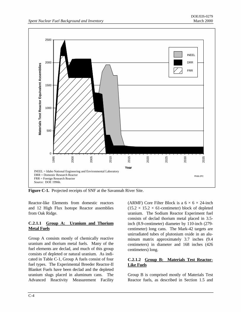
DOE/EIS-0279Spent Nuclear Fuel Background and Inventory March 2000
C-4
0
500
1000
1500
2000
2500
1995
2000
2005
2010
2015
2020
2025
2030
2035
Year
Mat
eria
ls T
est
Rea
cto
r E
qu
ival
ent
Ass
emb
lies
INEEL
DRR
FRR
PK66-2PC
Figure C-1. Projected receipts of SNF at the Savannah River Site.
Reactor-like Elements from domestic reactorsand 12 High Flux Isotope Reactor assembliesfrom Oak Ridge.
C.2.1.1 Group A: Uranium and ThoriumMetal Fuels
Group A consists mostly of chemically reactiveuranium and thorium metal fuels. Many of thefuel elements are declad, and much of this groupconsists of depleted or natural uranium. As indi-cated in Table C-1, Group A fuels consist of fourfuel types. The Experimental Breeder Reactor-IIBlanket Fuels have been declad and the depleteduranium slugs placed in aluminum cans. TheAdvanced Reactivity Measurement Facility
(ARMF) Core Filter Block is a 6 × 6 × 24-inch(15.2 × 15.2 × 61-centimeter) block of depleteduranium. The Sodium Reactor Experiment fuelconsists of declad thorium metal placed in 3.5-inch (8.9-centimeter) diameter by 110-inch (279-centimeter) long cans. The Mark-42 targets areunirradiated tubes of plutonium oxide in an alu-minum matrix approximately 3.7 inches (9.4centimeters) in diameter and 168 inches (426centimeters) long.
C.2.1.2 Group B: Materials Test Reactor-Like Fuels
Group B is comprised mostly of Materials TestReactor fuels, as described in Section 1.5 and
INEEL = Idaho National Engineering and Environmental LaboratoryDRR = Domestic Research ReactorFRR = Foreign Research ReactorSource: DOE 1996b.

DOE/EIS-0279March 2000 Spent Nuclear Fuel Background and Inventory
C-5
Figure 1-3, plus a few other fuels of similar sizeand composition. Table C-2 lists the Group Binventory
Table C-1. Inventory of Group A SNF.
Name Items Units Location
ExperimentalBreeder ReactorBlankets
59 Cans SRS WetBasinsa
ARMF Core FilterBlock
1 Filter INEEL
Sodium ReactorExperiment
36 Cans SRS WetBasins
Mark-42 16 Bundles SRS WetBasins
a. Receiving Basins for Offsite Fuel or L-ReactorDisassembly Basin.
ARMF = Advanced Reactivity Measurement Facil-ity
INEEL = Idaho National Engineering and Envi-ronmental Laboratory
C.2.1.3 Group C: HEU/LEU Oxides andSilicides Requiring Resizing or Special Pack-aging
Group C fuels are similar in composition toGroup B fuels in that they are aluminum-clad,highly enriched uranium and low enriched ura-nium oxides and silicides, but their size or shapeprecludes packaging without resizing or specialpackaging considerations. Some of the Group CSNF is smaller in diameter and longer thanGroup B fuels. Other fuel in this group is largerthan Group B fuels in both diameter and lengthand often comes in odd shapes such as 0.5-by-0.9-meter (1.5-by-3-foot) cylinders or sphereswith a diameter of 74 centimeters (29 inches).Table C-3 lists Group C inventory.
C.2.1.4 Group D: Loose Uranium Oxide inCans
Group D fuels consist of loose uranium oxideand fission products in aluminum cans. Ta-ble C-4 lists the Group D inventory.
The Sterling Forest Oxide material in this fuelgroup is a residue of highly enriched uranium,plutonium, fission products, mixed oxides (chro-mium, nickel, iron, barium), barium acetate, andbarium nitrate which resulted from the produc-tion of medical isotopes (primarily molybdenum99). The material was plated on the inside ofstainless steel tubes when it was irradiated. Thematerial was then removed from the tubes withan acid flush and the uranium was recoveredfrom a nitrate-sulfate solution, after eliminatingthe sulfate by precipitating with barium acetateand filtering. The filtrate was evaporated andpyrolyzed at 300ºC to an oxide form in an alumi-num can. The can was sealed and shipped toSRS where it was placed into storage in the Re-ceiving Basin for Offsite Fuels. Both the can andthe oxide powder it contains are readily dissolvedin acid.
The other items in this fuel group are liquid tar-gets that DOE assumes would be converted tooxide prior to shipment to SRS.
C.2.1.5 Group E: Higher Actinide Targets
Group E contains target materials used to gener-ate radionuclides with atomic numbers beyondthat of uranium. The targets are placed in nu-clear reactors and irradiated with neutrons, whichcauses nonfission nuclear reactions. These tar-gets are aluminum-clad plutonium oxide thatcontain significant quantities of americium andcurium, which react under neutron irradiation toproduce even higher atomic number elementssuch as californium. Table C-5 lists the Group Einventory.
C.2.1.6 Group F: Non-aluminum Clad Fuels
Group F comprises the large variety of non-aluminum-clad SNF at SRS that DOE must shipto the Idaho National Engineering and Environ-mental Laboratory under the Record of Decisionfor the Programmatic SNF EIS (DOE 1995a).Table C-6 lists the Group F inventory.
DOE/EIS-0279Spent Nuclear Fuel Background and Inventory March 2000
C-6
C.2.2 RADIONUCLIDE INVENTORY
The six SNF groups that DOE would manage atSRS possess diverse chemical, physical, and ra-diological characteristics. There is also diversitywithin any single fuel group. In the absence ofdetailed radionuclide characterization of the fuel,DOE has simplified the analyses for this EIS bydeveloping an analytical construction called aReference Fuel Assembly (Garrett et al. 1995).The Reference Fuel Assembly is used as a stan-dard reference for scaling fuel group characteris-tics. This assembly is a composite of depleteduranium, highly enriched uranium, and specialtarget radionuclides.
To determine the radionuclide inventories of eachfuel group, DOE calculated the ratio of radioac-tivity of each nuclide in the Reference Fuel As-
sembly to the fissile mass of the Reference FuelAssembly; multiplied the resulting ratios by thefissile mass of the fuel groups to obtain nuclide-specific inventories for each fuel group. DOEperformed an identical calculation based on totalheavy metal mass rather than fissile mass of eachfuel group. DOE conservatively used the calcu-lation (fissile mass ratio or total heavy metalmass ratio) that yielded the largest value of eachradionuclide to calculate the inventory of eachradionuclide for the fuel group. Scaling by fissilemass is important because the fission productspotentially produce most of the radiological im-pacts. Scaling by heavy metal mass is importantbecause heavy metal mass is an indicator ofprocessing time and provides appropriate repre-sentation of Group A fuels which contain littlefissile mass. Table C-7 lists the results of thesecalculations.

DOE/EIS-0279March 2000 Spent Nuclear Fuel Background and Inventory
C-7
Table C-2. Inventory of Group B SNF.Name Items Units Location
FRR MTR 10,812 Assemblies Argentina, Australia, Austria, Brazil, Canada, Chile, Co-lombia, France, Germany, Greece, Indonesia, Iran, Israel,Italy, Japan, Netherlands, Pakistan, Peru, Philippines,Portugal, South Africa, Spain, Sweden, Switzerland, Tai-wan, Thailand, Turkey, United Kingdom, Uruguay, Vene-zuela
DRR MTR 11,799 Assemblies LANL, INEEL, ORNL, Brookhaven National Laboratory,Massachusetts Institute of Technology, Georgia Institute ofTechnology, Iowa State University, University of Massa-chusetts-Lowell, University of Michigan, Missouri Univer-sity, Purdue University, Rhode Island Nuclear Center,University of Virginia, Worcester, National Institute ofStandards and Technology
MTR Approximately1,100
Assemblies SRS Wet Basinsa
Cylindrical MTR 145 Assemblies Japan
Box MTR 28 Assemblies Japan
Tube MTR 4,077 Assemblies Australia, Belgium, Denmark, Germany
Missouri UniversityResearch Reactor
224 Assemblies SRS Wet Basins, MURR, INEEL
Advanced TestReactor
3,132 Assemblies INEEL
Advanced ReactivityMeasurementFacility
67 Assemblies INEEL
University ofWashington
26 Bundles INEEL
Advanced ReactivityMeasurementFacility Plate
15 Plates INEEL
Sterling Forest Fuel 200 Assemblies SRS Wet Basins a. Receiving Basins for Offsite Fuel or L-Reactor Disassembly Basin.b. This value changes with FRR and DRR ongoing receipts. Some double counting with FRR and DRR entries
exists.LANL = Los Alamos National LaboratoryORNL = Oak Ridge National LaboratoryMTR = Materials Test ReactorFRR = Foreign Research ReactorMURR = Missouri University Research ReactorDRR = Domestic Research ReactorINEEL = Idaho National Engineering and Environmental Laboratory
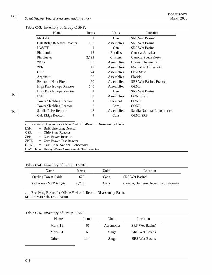
DOE/EIS-0279Spent Nuclear Fuel Background and Inventory March 2000
C-8
Table C-3. Inventory of Group C SNF.Name Items Units Location
Mark-14 1 Can SRS Wet Basinsa
Oak Ridge Research Reactor 165 Assemblies SRS Wet BasinsHWCTR 1 Can SRS Wet BasinsPin bundle 12 Bundles Canada, JamaicaPin cluster 2,792 Clusters Canada, South KoreaZPTR 45 Assemblies Cornell UniversityZPR 17 Assemblies Manhattan UniversityOSR 24 Assemblies Ohio StateArgonaut 50 Assemblies FloridaReactor a-Haut Flux 90 Assemblies SRS Wet Basins, FranceHigh Flux Isotope Reactor 540 Assemblies ORNLHigh Flux Isotope Reactor 1 Can SRS Wet BasinsBSR 32 Assemblies ORNL/SRSTower Shielding Reactor 1 Element ORNLTower Shielding Reactor 2 Cans ORNLSandia Pulse Reactor 43 Assemblies Sandia National LaboratoriesOak Ridge Reactor 9 Cans ORNL/SRS
a. Receiving Basins for Offsite Fuel or L-Reactor Disassembly Basin.BSR = Bulk Shielding ReactorOSR = Ohio State ReactorZPR = Zero Power ReactorZPTR = Zero Power Test ReactorORNL = Oak Ridge National LaboratoryHWCTR = Heavy Water Components Test Reactor
Table C-4. Inventory of Group D SNF.
Name Items Units Location
Sterling Forest Oxide 676 Cans SRS Wet Basinsa
Other non-MTR targets 6,750 Cans Canada, Belgium, Argentina, Indonesia
a. Receiving Basins for Offsite Fuel or L-Reactor Disassembly Basin.MTR = Materials Test Reactor
Table C-5. Inventory of Group E SNF.
Name Items Units Location
Mark-18 65 Assemblies SRS Wet Basinsa
Mark-51 60 Slugs SRS Wet Basins
Other 114 Slugs SRS Wet Basins
TC
TC
EC

DOE/EIS-0279March 2000 Spent Nuclear Fuel Background and Inventory
C-9
a. Receiving Basins for Offsite Fuel or L-Reactor Disassembly Basin.
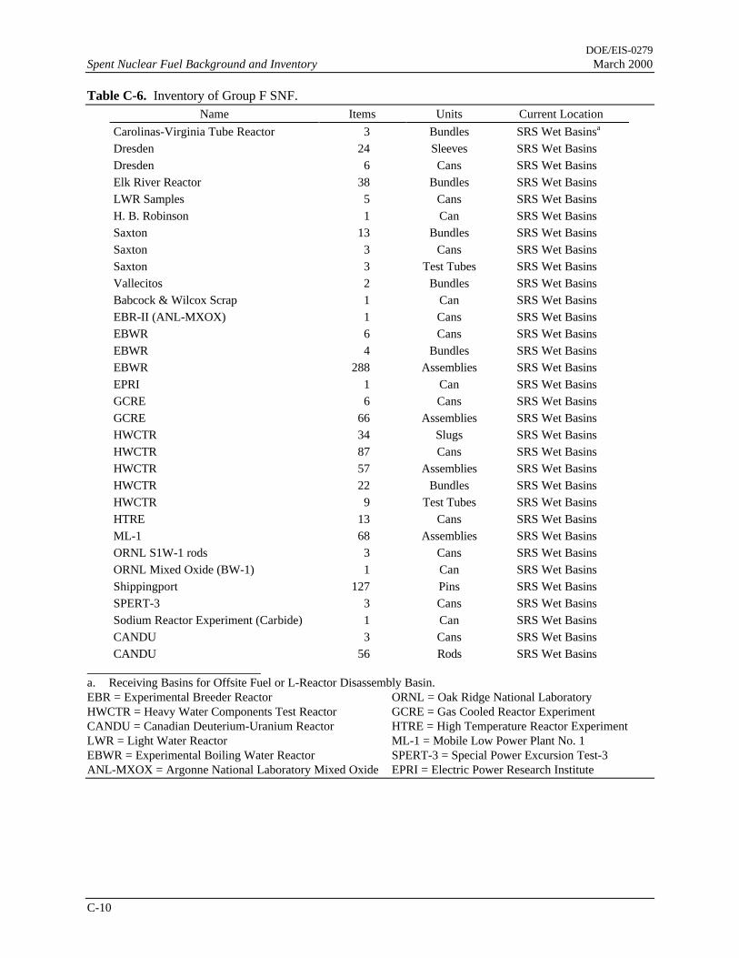
DOE/EIS-0279Spent Nuclear Fuel Background and Inventory March 2000
C-10
Table C-6. Inventory of Group F SNF.Name Items Units Current Location
Carolinas-Virginia Tube Reactor 3 Bundles SRS Wet Basinsa
Dresden 24 Sleeves SRS Wet BasinsDresden 6 Cans SRS Wet BasinsElk River Reactor 38 Bundles SRS Wet BasinsLWR Samples 5 Cans SRS Wet BasinsH. B. Robinson 1 Can SRS Wet BasinsSaxton 13 Bundles SRS Wet BasinsSaxton 3 Cans SRS Wet BasinsSaxton 3 Test Tubes SRS Wet BasinsVallecitos 2 Bundles SRS Wet BasinsBabcock & Wilcox Scrap 1 Can SRS Wet BasinsEBR-II (ANL-MXOX) 1 Cans SRS Wet BasinsEBWR 6 Cans SRS Wet BasinsEBWR 4 Bundles SRS Wet BasinsEBWR 288 Assemblies SRS Wet BasinsEPRI 1 Can SRS Wet BasinsGCRE 6 Cans SRS Wet BasinsGCRE 66 Assemblies SRS Wet BasinsHWCTR 34 Slugs SRS Wet BasinsHWCTR 87 Cans SRS Wet BasinsHWCTR 57 Assemblies SRS Wet BasinsHWCTR 22 Bundles SRS Wet BasinsHWCTR 9 Test Tubes SRS Wet BasinsHTRE 13 Cans SRS Wet BasinsML-1 68 Assemblies SRS Wet BasinsORNL S1W-1 rods 3 Cans SRS Wet BasinsORNL Mixed Oxide (BW-1) 1 Can SRS Wet BasinsShippingport 127 Pins SRS Wet BasinsSPERT-3 3 Cans SRS Wet BasinsSodium Reactor Experiment (Carbide) 1 Can SRS Wet BasinsCANDU 3 Cans SRS Wet BasinsCANDU 56 Rods SRS Wet Basins
a. Receiving Basins for Offsite Fuel or L-Reactor Disassembly Basin.EBR = Experimental Breeder Reactor ORNL = Oak Ridge National LaboratoryHWCTR = Heavy Water Components Test Reactor GCRE = Gas Cooled Reactor ExperimentCANDU = Canadian Deuterium-Uranium Reactor HTRE = High Temperature Reactor ExperimentLWR = Light Water Reactor ML-1 = Mobile Low Power Plant No. 1EBWR = Experimental Boiling Water Reactor SPERT-3 = Special Power Excursion Test-3ANL-MXOX = Argonne National Laboratory Mixed Oxide EPRI = Electric Power Research Institute

DOE/EIS-0279March 2000 Spent Nuclear Fuel Background and Inventory
C-11
Table C-7. Radionuclide inventories based on the Reference Fuel Assembly (curies).Fuel Group
Nuclidea
Reference FuelAssembly A B C D E F
H-3 51.6 2540 144,000 46,000 9,090 112 9,780Kr-85 1,050 51,700 2,920,000 935,000 185,000 2,270 199,000Sr-89 49.2 2420 137000 43800 8670 107 9320Sr-90 8,080 398,000 22,500,000 7,200,000 1,420,000 17,500 1,530,000Y-90 8,080 398,000 22,500,000 7,200,000 1,420,000 17,500 1,530,000Y-91 213 10,500 593,000 190,000 37,500 461 40,400Zr-95 454 22,400 1,260,000 404,000 80,000 983 86,000Nb-95 1,010 49,800 2,810,000 899,000 178,000 2,190 191,000Nb-95m 3.37 166 9,390 3,000 594 7.30 639Tc-99 1.03 50.7 2,870 917 181 2.23 195Rh-103m 1.96 96.6 5,460 1,750 345 4.25 371Rh-106 21,100 1,040,000 58,800,000 18,800,000 3,720,000 45,700 4,000,000Ru-103 2.17 107 6,040 1,930 382 4.70 411Ru-106 21,100 1,040,000 58,800,000 18,800,000 3,720,000 45,700 4,000,000Ag-110 2.32 114 6,460 2,070 409 5.03 440Ag-110m 174 8,570 485,000 155,000 30,700 377 33,000Cd-113m 6.95 342 19,400 6,190 1,220 15.1 1,320Sn-119m 3.93 194 10,900 3,500 693 8.51 745Sn-123 14.5 714 40,400 12,900 2,560 31.4 2,750Sb-125 870 42,900 2,420,000 775,000 153,000 1,880 165,000Te-125m 212 10,400 590,000 189,000 37,400 459 40,200Te-127 34.7 1,710 96,600 30,900 6,110 75.2 6,570Te-127m 35.4 1,740 98,600 31,500 6,240 76.7 6,710Te-129 0.0012 591 3.34 1.07 0.211 0.0026 0.227Te-129m 0.00185 911 5.15 1.65 0.326 0.00401 0.351Cs-134 10,300 507,000 28,700,000 9,170,000 1,810,000 22,300 1,950,000Cs-137 9,280 457,000 25,800,000 8,260,000 1,640,000 20,100 1,760,000Ba-137m 8,780 433,000 24,500,000 7,820,000 1,550,000 19,000 1,660,000Ce-141 0.0646 3.18 180 57.5 11.4 0.140 12.2Ce-144 47,800 2,350,000 133,000,000 42,600,000 8,420,000 104,000 9,060,000Pr-144 47,800 2,350,000 133,000,000 42,600,000 8,420,000 104,000 9,060,000Pr-144m 574 28,300 1,600,000 511,000 101,000 1,240 109,000Pm-147 18,800 926,000 52,400,000 16,700,000 3,310,000 40,700 3,560,000Pm-148m 0.00893 0.44 24.9 7.95 1.57 0.0193 1.69Sm-151 69.4 3,420 193,000 61,800 12,200 150 13,100Eu-154 727 35,800 2,020,000 647,000 128,000 1,570 138,000Eu-155 381 18,800 1,060,000 339,000 67,100 825 72,200Tl-208 8.46 417 23,600 7,530 1,490 18.3 1,600Pb-209 0.00874 0.431 24.3 7.78 1.54 0.0189 1.66Pb-211 0.0166 0.818 46.2 14.8 2.93 0.036 3.15Pb-212 23.6 1,160 65,700 21,000 4,160 51.1 4,470Bi-211 0.0166 0.818 46.2 14.8 2.93 0.036 3.15Bi-212 23.6 1,160 65,700 21,000 4,160 51.1 4,470Bi-213 0.00874 0.431 24.3 7.78 1.54 0.0189 1.66Po-212 15.1 744 42,100 13,400 2,660 32.7 2,860Po-213 0.00855 0.421 23.8 7.61 1.51 0.0185 1.62
EC

DOE/EIS-0279Spent Nuclear Fuel Background and Inventory March 2000
C-12
Table C-7. (continued).Reference Fuel Fuel Group
Nuclidea Assembly A B C D E F
Po-215 0.0166 0.818 46.2 14.8 2.93 0.036 3.15Po-216 23.6 1,160 65,700 21,000 4,160 51.1 4,470At-217 0.00874 0.431 24.3 7.78 1.54 0.0189 1.66Rn-219 0.0166 0.818 46.2 14.8 2.93 0.036 3.15Rn-220 23.6 1,160 65,700 21,000 4,160 51.1 4,470Fr-221 0.00874 0.431 24.3 7.78 1.54 0.0189 1.66Ra-223 0.0166 0.818 46.2 14.8 2.93 0.036 3.15Ra-224 23.6 1,160 65,700 21,000 4,160 51.1 4,470Ra-225 0.00874 0.431 24.3 7.78 1.54 0.0189 1.66Ac-225 0.00874 0.431 24.3 7.78 1.54 0.0189 1.66Ac-227 0.0171 0.842 47.6 15.2 3.01 0.037 3.24Th-227 0.0164 0.808 45.7 14.6 2.89 0.0355 3.11Th-228 23.5 1160 65,500 20,900 4,140 50.9 4,450Th-229 0.00874 0.431 24.3 7.78 1.54 0.0189 1.66Th-231 0.0114 0.562 31.8 10.2 2.01 0.0247 2.16Th-232 0.0172 0.847 47.9 15.3 3.03 0.0373 3.26Th-234 0.000216 0.0106 0.602 0.192 0.0381 0.000468 0.0409Pa-231 0.228 11.2 635 203 40.2 0.494 43.2Pa-233 0.0859 4.23 239 76.5 15.1 0.186 16.3Pa-234m 0.000216 0.0106 0.602 0.192 0.0381 0.000468 0.0409U-232 40.9 2,010 114,000 36,400 7,210 88.6 7,750U-233 39.3 1,940 109,000 35,000 6,930 85.1 7,450U-234 1.92 94.6 5,350 1,710 338 4.16 364U-235 0.0114 0.562 31.8 10.2 2.01 0.0247 2.16U-236 0.0329 1.62 91.6 29.3 5.80 0.0713 6.23U-237 0.259 12.8 721 231 45.6 0.561 49.1U-238 0.0842 4.15 235 75.0 14.8 0.182 16.0Np-237 0.00881 0.434 24.5 7.85 1.55 0.02 1.67Np-239 9.62 474 26,800 8,570 1,700 21 1,820Pu-236 112 5,520 312,000 99,700 19,700 250 21,200Pu-238 51.9 2,560 145,000 46,200 9,150 340 9,830Pu-239 58 2,860 162,000 51,700 10,200 130 11,000Pu-240 9,780 482,000 27,200,000 8,710,000 1,720,000 23,000 1,850,000Pu-241 10,600 522,000 29,500,000 9,440,000 1,870,000 23,000 2,010,000Am-241 51.7 2,550 144,000 46,000 9,110 450 9,800Am-242 0.34 16.7 947 303 59.9 0.74 64.4Am-242m 0.341 16.8 950 304 60.1 0.74 64.6Am-243 9.62 474 26,800 8,570 1,700 21 1,820Cm-242 490 24,100 1,360,000 436,000 86,300 1,100 92,800Cm-243 4.9 241 13,600 4,360 863 11 928Cm-244 2,750 135,000 7,660,000 2,450,000 485,000 18,000 521,000Cm-246 0.215 10.6 599 191 37.9 150 40.7Totals 231,000 11,400,000 644,000,000 206,000,000 40,700,000 520,000 43,800,000 a. Refer to Table C-8 for the names of the elements.

DOE/EIS-0279March 2000 Spent Nuclear Fuel Background and Inventory
C-13
Table C-8. Chemical symbols used in Table C-7 and the corresponding element names.H-3 = tritiumKr = kryptonSr = strontiumY = yttriumZr = zirconiumNb = niobiumTc = technetiumRh = rhodiumRu = rutheniumAg = silverCd = cadmiumSn = tinSb = antimonyTe = telluriumCs = cesiumBa = bariumCe = ceriumPr = praseodymiumPm = promethiumSm = samariumEu = europiumTl = thalliumPb = leadBi = bismuthPo = poloniumAt = astatineRn = radonFr = franciumRa = radiumAc = actiniumTh = thoriumPa = protactiniumU = uraniumNp = neptuniumPu = plutoniumAm = americiumCm = curium
EC

DOE/EIS-0279Spent Nuclear Fuel Background and Inventory March 2000
C-14
References
DOE (U.S. Department of Energy), 1995a, Final Programmatic Spent Nuclear Fuel Management andIdaho National Engineering Laboratory Environmental Restoration and Waste ManagementPrograms Environmental Impact Statement, DOE/EIS-0203, Idaho Operations Office, Idaho Falls,Idaho.
DOE (U.S. Department of Energy), 1995b, Final Environmental Impact Statement, Interim Managementof Nuclear Materials, DOE/EIS-0220, Savannah River Site, Aiken, South Carolina.
DOE (U.S. Department of Energy), 1996a, Final Environmental Impact Statement on a Proposed NuclearWeapons Nonproliferation Policy Concerning Research Reactor Spent Nuclear Fuel, DOE/EIS-0218F, Washington, D.C.
DOE (U.S. Department of Energy), 1996b, Technical Strategy for the Treatment, Packaging, andDisposal of Aluminum Based Spent Nuclear Fuel, A Report of the Research Reactor Spent NuclearFuel Task Team, Volume I, Washington, D.C.
Garrett, R. L., S. D. Kahook, L. R. Canas, and M. J. Beckum, 1995, “Spent Nuclear Fuel Characterizationfor a Bounding Reference Assembly for the Receiving Basin for Offsite Fuel,” Nuclear Safety, 36:2,U.S. Department of Energy Office of Scientific and Technical Information, Oak Ridge, Tennessee,July-December.

DOE/EIS-0279March 2000 Spent Nuclear Fuel Background and Inventory
C-15
cesium, 12
criticality, 1, 2
DOE, 1, 2, 3, 5, 6
F Canyon, 3
geologic repository, 3
Group A, 4, 6
Group B, 5, 7
Group C, 5, 8
Group D, 5, 8
Group E,5, 8
Group F, 5, 9
heavy metal, 1, 6
HEU,1, 5
Idaho National Engineering and Environmental
Laboratory, 2, 4, 5, 7
impacts, 2, 6
INEEL, 4, 7
LEU, iii, 1, 5
Low-enriched uranium, 1
L-Reactor Disassembly Basin, 3, 4, 7, 8, 9
Mark-18 targets, 3
Mark-42 targets, 5
plutonium, 1, 5, 12
process, 1
Receiving Basin for Offsite Fuel, 2, 3, 5,
processing, 2
Savannah River Site, iii, 2, 4,
Sodium Reactor Experiment fuel, 4
uranium, 1, 3, 4, 5, 6, 12
EC

APPENDIX C
SPENT NUCLEAR FUEL BACKGROUNDAND INVENTORY

DOE/EIS-0279March 2000 Spent Nuclear Fuel Background and Inventory
C-iii
TABLE OF CONTENTS
Section Page
C.1 Background .................................................................................................................... C-1C.1.1 General characteristics........................................................................................ C-1C.1.2 Recent Spent Fuel Management Actions.............................................................. C-2
C.2 Inventory ........................................................................................................................ C-3C.2.1 Physical Inventory .............................................................................................. C-3
C.2.1.1 Group A: Uranium and Thorium Metal Fuels ..................................... C-4C.2.1.2 Group B: Materials Test Reactor-Like Fuels ...................................... C-4C.2.1.3 Group C: HEU/LEU Oxides and Silicides Requiring Resizing or
Special Packaging............................................................................... C-5C.2.1.4 Group D: Loose Uranium Oxide in Cans ............................................ C-5C.2.1.5 Group E: Higher Actinide Targets ...................................................... C-5C.2.1.6 Group F: Non-aluminum Clad Fuels................................................... C-5
C.2.2 Radionuclide Inventory....................................................................................... C-6References ................................................................................................................................. C-14
List of Tables
Table Page
C-1 Inventory of Group A SNF ......................................................................................... C-5C-2 Inventory of Group B SNF ......................................................................................... C-7C-3 Inventory of Group C SNF ......................................................................................... C-8C-4 Inventory of Group D SNF......................................................................................... C-8C-5 Inventory of Group E SNF ......................................................................................... C-8C-6 Inventory of Group F SNF.......................................................................................... C-10C-7 Radionuclide inventories based on the Reference Fuel Assembly.................................. C-11C-8 Chemical symbols used in Table C-7 and the corresponding element names ................. C-13
List of Figure
Figure Page
C-1 Projected receipts of SNF at the Savannah River Site.................................................. C-4


DOE/EIS-0279March 2000 Spent Nuclear Fuel Background and Inventory
C-1
APPENDIX C. SPENT NUCLEAR FUEL BACKGROUNDAND INVENTORY
C.1 Background
C.1.1 GENERAL CHARACTERISTICS
In nuclear reactors a process occurs known as thefission chain reaction, in which atomic nuclei inreactor fuel respond to collisions with neutronsby splitting into two major fragments and two orthree neutrons. The neutrons can interact withother fuel nuclei, thereby continuing the chainreaction.
In comparison to a chemical reaction involvingthe same mass, a nuclear reaction releases a largeamount of energy, mostly the kinetic energy ofthe fission fragments and neutrons and the subse-quent radioactive decay of the fission fragments(fission products). This energy makes nuclearfission an attractive source of energy for com-mercial power producers. DOE operated its pro-duction reactors principally because the neutronscaused nonfission nuclear reactions of interest tonational defense (i.e., isotopic transmutation).Research reactors use the fission process to pro-duce medical isotopes or for other research pur-poses.
Nuclear fuel must contain atoms that can be fis-sioned (called fission atoms). Fission atoms arefissioned by low-energy (thermal) neutrons.Therefore, to maintain the chain reaction, thehigh energy, fast neutrons produced by fissionmust be slowed to low-energy, thermal neutrons.The process for slowing down the neutrons iscalled moderation: water, graphite, and heavywater are used as moderators.
Uranium-235 is the fissile atom used most oftenfor nuclear fuel; however, other fissile materials(uranium-233, plutonium-239, and plutonium-241) can be used in nuclear reactors. Uranium-235 represents only about 0.7 percent of the at-oms of natural uranium, which is primarily ura-nium-238. Therefore, many reactors use fuelthat has an enriched uranium-235 content.
Commercial power reactors typically use fuelsenriched to approximately 2 to 4 percent. Non-commercial reactors, depending on their purpose,use fuel enriched to as much as 93 percent ura-nium-235. Low-enriched uranium (LEU) has anenrichment below 20 percent; highly enricheduranium (HEU) is enriched 20 percent or higher.The fuels discussed in this EIS are primarilyhighly enriched uranium fuels.
The uranium in nuclear fuels generally is cladwith a metal to protect it from chemical reactionswith the moderator water and to prevent the re-lease of fission products to the water. Zirco-nium, stainless steel, and aluminum are commoncladding materials. Most of the SNF analyzed inthis EIS (about 48 metric tons heavy metal[MTHM]) is aluminum-clad; the remainder isclad with stainless steel or zirconium.
Inside the cladding, the fuel is often in the formof a ceramic, an alloy that combines uraniumwith aluminum, metallic uranium, or a uraniumoxide or silicide. The fuel can be assembled asparallel plates, concentric tubes, bundles of rodsor pins, or other designs. Each assembly hasmounting and lifting hardware, structures to di-rect coolant and moderator flow, and in somecases the capability to install neutron absorbingmaterial and instrumentation. Usually a numberof fuel assemblies make up a complete reactorcore.
Spent nuclear fuel (SNF) is fuel that has beenirradiated in a reactor and contains fissile atomsand fission products. SNF management mustconsider four fuel characteristics: radiationfields, heat generation, criticality, and chemicalstability (corrosion resistance). As the fuel isirradiated in a reactor, much of the uranium isburned, resulting in the production of fissionproducts. These fission products are radioactive;that is, they do not undergo fission but they radi-ate energy and transmute to other elements. SNFhas very high radiation fields, especially for a
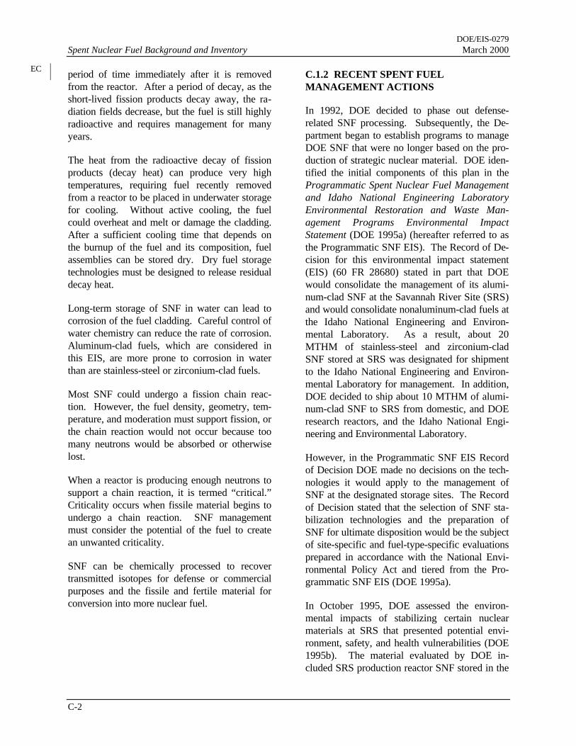
DOE/EIS-0279Spent Nuclear Fuel Background and Inventory March 2000
C-2
period of time immediately after it is removedfrom the reactor. After a period of decay, as theshort-lived fission products decay away, the ra-diation fields decrease, but the fuel is still highlyradioactive and requires management for manyyears.
The heat from the radioactive decay of fissionproducts (decay heat) can produce very hightemperatures, requiring fuel recently removedfrom a reactor to be placed in underwater storagefor cooling. Without active cooling, the fuelcould overheat and melt or damage the cladding.After a sufficient cooling time that depends onthe burnup of the fuel and its composition, fuelassemblies can be stored dry. Dry fuel storagetechnologies must be designed to release residualdecay heat.
Long-term storage of SNF in water can lead tocorrosion of the fuel cladding. Careful control ofwater chemistry can reduce the rate of corrosion.Aluminum-clad fuels, which are considered inthis EIS, are more prone to corrosion in waterthan are stainless-steel or zirconium-clad fuels.
Most SNF could undergo a fission chain reac-tion. However, the fuel density, geometry, tem-perature, and moderation must support fission, orthe chain reaction would not occur because toomany neutrons would be absorbed or otherwiselost.
When a reactor is producing enough neutrons tosupport a chain reaction, it is termed “critical.”Criticality occurs when fissile material begins toundergo a chain reaction. SNF managementmust consider the potential of the fuel to createan unwanted criticality.
SNF can be chemically processed to recovertransmitted isotopes for defense or commercialpurposes and the fissile and fertile material forconversion into more nuclear fuel.
C.1.2 RECENT SPENT FUELMANAGEMENT ACTIONS
In 1992, DOE decided to phase out defense-related SNF processing. Subsequently, the De-partment began to establish programs to manageDOE SNF that were no longer based on the pro-duction of strategic nuclear material. DOE iden-tified the initial components of this plan in theProgrammatic Spent Nuclear Fuel Managementand Idaho National Engineering LaboratoryEnvironmental Restoration and Waste Man-agement Programs Environmental ImpactStatement (DOE 1995a) (hereafter referred to asthe Programmatic SNF EIS). The Record of De-cision for this environmental impact statement(EIS) (60 FR 28680) stated in part that DOEwould consolidate the management of its alumi-num-clad SNF at the Savannah River Site (SRS)and would consolidate nonaluminum-clad fuels atthe Idaho National Engineering and Environ-mental Laboratory. As a result, about 20MTHM of stainless-steel and zirconium-cladSNF stored at SRS was designated for shipmentto the Idaho National Engineering and Environ-mental Laboratory for management. In addition,DOE decided to ship about 10 MTHM of alumi-num-clad SNF to SRS from domestic, and DOEresearch reactors, and the Idaho National Engi-neering and Environmental Laboratory.
However, in the Programmatic SNF EIS Recordof Decision DOE made no decisions on the tech-nologies it would apply to the management ofSNF at the designated storage sites. The Recordof Decision stated that the selection of SNF sta-bilization technologies and the preparation ofSNF for ultimate disposition would be the subjectof site-specific and fuel-type-specific evaluationsprepared in accordance with the National Envi-ronmental Policy Act and tiered from the Pro-grammatic SNF EIS (DOE 1995a).
In October 1995, DOE assessed the environ-mental impacts of stabilizing certain nuclearmaterials at SRS that presented potential envi-ronment, safety, and health vulnerabilities (DOE1995b). The material evaluated by DOE in-cluded SRS production reactor SNF stored in the
EC

DOE/EIS-0279March 2000 Spent Nuclear Fuel Background and Inventory
C-3
reactor disassembly basins and research reactorSNF stored in the Receiving Basin for OffsiteFuel. The Department decided to stabilize SNFthat presented potential environmental, safety,and health vulnerabilities by processing the mate-rial through the existing chemical separationsfacilities at SRS. Under these decisions(60 FR 65300, 61 FR 6633, and 62 FR 17790),about 175 MTHM of the approximately195 MTHM of SNF at SRS will be stabilized.After stabilization, the resulting material will betreated and managed so that it is acceptable forpermanent disposition once those decisions aremade. DOE concluded the remaining material,all of which was stored in the Receiving Basinfor Offsite Fuel, was stable and could remain asis for several years pending disposition decisions.In addition, DOE decided some of the stable ma-terial might have programmatic value, that is, beof use to future DOE missions. Mark-18 targetsstored in the Receiving Basin for Offsite Fuelcould be shipped to other DOE sites for pro-grammatic uses, including irradiation fortransuranium isotope production (primarily forNational Aeronautics and Space Administrationuse) and defense stockpile stewardship activities.
In May 1996 DOE issued its Record of Decision(61 FR 25092) for the Final Environmental Im-pact Statement on a Proposed Nuclear WeaponsNonproliferation Policy Concerning ForeignResearch Reactor [FRR] Spent Nuclear Fuel(DOE 1996a) (hereafter referred to as the FRREIS). The Department decided to accept andmanage foreign research reactor SNF that con-tains uranium enriched in the United States. Inkeeping with its 1995 programmatic decision (60FR 28680), DOE decided it would manage thealuminum-clad portion of the foreign researchreactor SNF, about 18 MTHM, at SRS. Underthe foreign research reactor receipt program,shipments from foreign reactors to SRS began inSeptember 1996 and could continue for as longas 13 years. At present, SRS is receiving thisfuel in either the Receiving Basin for Offsite Fuelor the L-Reactor Disassembly Basin. Figure C-1shows projected receipts of aluminum-clad SNFat SRS from foreign and domestic sources, basedon 1996 estimates. Because some countries may
choose not to participate in the return of foreignSNF, the amount of aluminum-based foreignSNF to be managed at SRS may be less.
The May 1996 decision to accept foreign re-search reactor SNF for management in the UnitedStates (61 FR 25092) stated that DOE wouldissue a separate Record of Decision, after appro-priate environmental reviews, to announce itsplans for the management of such fuel. The De-partment committed to the aggressive pursuit ofone or more new packaging or non-processingtechnologies that would put foreign research re-actor SNF in a form or container suitable fordisposal in a geologic repository. DOE alsocommitted to place foreign research reactor SNFin dry storage at SRS (after required treatment orpackaging) pending offsite storage or disposal.DOE also stated that if a new treatment technol-ogy was not ready for implementation by 2000,DOE would consider the chemical separation ofsome foreign reactor SNF that would blend thematerial down to low-enriched uranium in FCanyon at SRS. DOE might then place it underInternational Atomic Energy Agency safeguards.
C.2 Inventory
C.2.1 PHYSICAL INVENTORY
As Figure C-1 indicates, most SNF receiptswould occur before 2015; however, SRS willcontinue to receive small amounts over the entireperiod of analysis (until 2035). There is greatvariety in the SNF that SRS must manage overthe next 40 years. Therefore, DOE has catego-rized the SNF into six groups to facilitate analy-sis. The SNF in each category should receivenearly identical management. The basis for thecategorization was often the size of the fuel inrelation to packaging; however, other considera-tions were included such as physical characteris-tics, chemical characteristics, and radionuclidecontent. For example, one category includes allSNF in powder form. The following subsectionsdescribe the six fuel groups and list the SNF in-ventory associated associated with each group.Receipts per year will be aproximately 150 Ma-terials Test
M4-13

DOE/EIS-0279Spent Nuclear Fuel Background and Inventory March 2000
C-4
0
500
1000
1500
2000
2500
1995
2000
2005
2010
2015
2020
2025
2030
2035
Year
Mat
eria
ls T
est
Rea
cto
r E
qu
ival
ent
Ass
emb
lies
INEEL
DRR
FRR
PK66-2PC
Figure C-1. Projected receipts of SNF at the Savannah River Site.
Reactor-like Elements from domestic reactorsand 12 High Flux Isotope Reactor assembliesfrom Oak Ridge.
C.2.1.1 Group A: Uranium and ThoriumMetal Fuels
Group A consists mostly of chemically reactiveuranium and thorium metal fuels. Many of thefuel elements are declad, and much of this groupconsists of depleted or natural uranium. As indi-cated in Table C-1, Group A fuels consist of fourfuel types. The Experimental Breeder Reactor-IIBlanket Fuels have been declad and the depleteduranium slugs placed in aluminum cans. TheAdvanced Reactivity Measurement Facility
(ARMF) Core Filter Block is a 6 × 6 × 24-inch(15.2 × 15.2 × 61-centimeter) block of depleteduranium. The Sodium Reactor Experiment fuelconsists of declad thorium metal placed in 3.5-inch (8.9-centimeter) diameter by 110-inch (279-centimeter) long cans. The Mark-42 targets areunirradiated tubes of plutonium oxide in an alu-minum matrix approximately 3.7 inches (9.4centimeters) in diameter and 168 inches (426centimeters) long.
C.2.1.2 Group B: Materials Test Reactor-Like Fuels
Group B is comprised mostly of Materials TestReactor fuels, as described in Section 1.5 and
INEEL = Idaho National Engineering and Environmental LaboratoryDRR = Domestic Research ReactorFRR = Foreign Research ReactorSource: DOE 1996b.
DOE/EIS-0279March 2000 Spent Nuclear Fuel Background and Inventory
C-5
Figure 1-3, plus a few other fuels of similar sizeand composition. Table C-2 lists the Group Binventory
Table C-1. Inventory of Group A SNF.
Name Items Units Location
ExperimentalBreeder ReactorBlankets
59 Cans SRS WetBasinsa
ARMF Core FilterBlock
1 Filter INEEL
Sodium ReactorExperiment
36 Cans SRS WetBasins
Mark-42 16 Bundles SRS WetBasins
a. Receiving Basins for Offsite Fuel or L-ReactorDisassembly Basin.
ARMF = Advanced Reactivity Measurement Facil-ity
INEEL = Idaho National Engineering and Envi-ronmental Laboratory
C.2.1.3 Group C: HEU/LEU Oxides andSilicides Requiring Resizing or Special Pack-aging
Group C fuels are similar in composition toGroup B fuels in that they are aluminum-clad,highly enriched uranium and low enriched ura-nium oxides and silicides, but their size or shapeprecludes packaging without resizing or specialpackaging considerations. Some of the Group CSNF is smaller in diameter and longer thanGroup B fuels. Other fuel in this group is largerthan Group B fuels in both diameter and lengthand often comes in odd shapes such as 0.5-by-0.9-meter (1.5-by-3-foot) cylinders or sphereswith a diameter of 74 centimeters (29 inches).Table C-3 lists Group C inventory.
C.2.1.4 Group D: Loose Uranium Oxide inCans
Group D fuels consist of loose uranium oxideand fission products in aluminum cans. Ta-ble C-4 lists the Group D inventory.
The Sterling Forest Oxide material in this fuelgroup is a residue of highly enriched uranium,plutonium, fission products, mixed oxides (chro-mium, nickel, iron, barium), barium acetate, andbarium nitrate which resulted from the produc-tion of medical isotopes (primarily molybdenum99). The material was plated on the inside ofstainless steel tubes when it was irradiated. Thematerial was then removed from the tubes withan acid flush and the uranium was recoveredfrom a nitrate-sulfate solution, after eliminatingthe sulfate by precipitating with barium acetateand filtering. The filtrate was evaporated andpyrolyzed at 300ºC to an oxide form in an alumi-num can. The can was sealed and shipped toSRS where it was placed into storage in the Re-ceiving Basin for Offsite Fuels. Both the can andthe oxide powder it contains are readily dissolvedin acid.
The other items in this fuel group are liquid tar-gets that DOE assumes would be converted tooxide prior to shipment to SRS.
C.2.1.5 Group E: Higher Actinide Targets
Group E contains target materials used to gener-ate radionuclides with atomic numbers beyondthat of uranium. The targets are placed in nu-clear reactors and irradiated with neutrons, whichcauses nonfission nuclear reactions. These tar-gets are aluminum-clad plutonium oxide thatcontain significant quantities of americium andcurium, which react under neutron irradiation toproduce even higher atomic number elementssuch as californium. Table C-5 lists the Group Einventory.
C.2.1.6 Group F: Non-aluminum Clad Fuels
Group F comprises the large variety of non-aluminum-clad SNF at SRS that DOE must shipto the Idaho National Engineering and Environ-mental Laboratory under the Record of Decisionfor the Programmatic SNF EIS (DOE 1995a).Table C-6 lists the Group F inventory.

DOE/EIS-0279Spent Nuclear Fuel Background and Inventory March 2000
C-6
C.2.2 RADIONUCLIDE INVENTORY
The six SNF groups that DOE would manage atSRS possess diverse chemical, physical, and ra-diological characteristics. There is also diversitywithin any single fuel group. In the absence ofdetailed radionuclide characterization of the fuel,DOE has simplified the analyses for this EIS bydeveloping an analytical construction called aReference Fuel Assembly (Garrett et al. 1995).The Reference Fuel Assembly is used as a stan-dard reference for scaling fuel group characteris-tics. This assembly is a composite of depleteduranium, highly enriched uranium, and specialtarget radionuclides.
To determine the radionuclide inventories of eachfuel group, DOE calculated the ratio of radioac-tivity of each nuclide in the Reference Fuel As-
sembly to the fissile mass of the Reference FuelAssembly; multiplied the resulting ratios by thefissile mass of the fuel groups to obtain nuclide-specific inventories for each fuel group. DOEperformed an identical calculation based on totalheavy metal mass rather than fissile mass of eachfuel group. DOE conservatively used the calcu-lation (fissile mass ratio or total heavy metalmass ratio) that yielded the largest value of eachradionuclide to calculate the inventory of eachradionuclide for the fuel group. Scaling by fissilemass is important because the fission productspotentially produce most of the radiological im-pacts. Scaling by heavy metal mass is importantbecause heavy metal mass is an indicator ofprocessing time and provides appropriate repre-sentation of Group A fuels which contain littlefissile mass. Table C-7 lists the results of thesecalculations.

DOE/EIS-0279March 2000 Spent Nuclear Fuel Background and Inventory
C-7
Table C-2. Inventory of Group B SNF.Name Items Units Location
FRR MTR 10,812 Assemblies Argentina, Australia, Austria, Brazil, Canada, Chile, Co-lombia, France, Germany, Greece, Indonesia, Iran, Israel,Italy, Japan, Netherlands, Pakistan, Peru, Philippines,Portugal, South Africa, Spain, Sweden, Switzerland, Tai-wan, Thailand, Turkey, United Kingdom, Uruguay, Vene-zuela
DRR MTR 11,799 Assemblies LANL, INEEL, ORNL, Brookhaven National Laboratory,Massachusetts Institute of Technology, Georgia Institute ofTechnology, Iowa State University, University of Massa-chusetts-Lowell, University of Michigan, Missouri Univer-sity, Purdue University, Rhode Island Nuclear Center,University of Virginia, Worcester, National Institute ofStandards and Technology
MTR Approximately1,100
Assemblies SRS Wet Basinsa
Cylindrical MTR 145 Assemblies Japan
Box MTR 28 Assemblies Japan
Tube MTR 4,077 Assemblies Australia, Belgium, Denmark, Germany
Missouri UniversityResearch Reactor
224 Assemblies SRS Wet Basins, MURR, INEEL
Advanced TestReactor
3,132 Assemblies INEEL
Advanced ReactivityMeasurementFacility
67 Assemblies INEEL
University ofWashington
26 Bundles INEEL
Advanced ReactivityMeasurementFacility Plate
15 Plates INEEL
Sterling Forest Fuel 200 Assemblies SRS Wet Basins a. Receiving Basins for Offsite Fuel or L-Reactor Disassembly Basin.b. This value changes with FRR and DRR ongoing receipts. Some double counting with FRR and DRR entries
exists.LANL = Los Alamos National LaboratoryORNL = Oak Ridge National LaboratoryMTR = Materials Test ReactorFRR = Foreign Research ReactorMURR = Missouri University Research ReactorDRR = Domestic Research ReactorINEEL = Idaho National Engineering and Environmental Laboratory

DOE/EIS-0279Spent Nuclear Fuel Background and Inventory March 2000
C-8
Table C-3. Inventory of Group C SNF.Name Items Units Location
Mark-14 1 Can SRS Wet Basinsa
Oak Ridge Research Reactor 165 Assemblies SRS Wet BasinsHWCTR 1 Can SRS Wet BasinsPin bundle 12 Bundles Canada, JamaicaPin cluster 2,792 Clusters Canada, South KoreaZPTR 45 Assemblies Cornell UniversityZPR 17 Assemblies Manhattan UniversityOSR 24 Assemblies Ohio StateArgonaut 50 Assemblies FloridaReactor a-Haut Flux 90 Assemblies SRS Wet Basins, FranceHigh Flux Isotope Reactor 540 Assemblies ORNLHigh Flux Isotope Reactor 1 Can SRS Wet BasinsBSR 32 Assemblies ORNL/SRSTower Shielding Reactor 1 Element ORNLTower Shielding Reactor 2 Cans ORNLSandia Pulse Reactor 43 Assemblies Sandia National LaboratoriesOak Ridge Reactor 9 Cans ORNL/SRS
a. Receiving Basins for Offsite Fuel or L-Reactor Disassembly Basin.BSR = Bulk Shielding ReactorOSR = Ohio State ReactorZPR = Zero Power ReactorZPTR = Zero Power Test ReactorORNL = Oak Ridge National LaboratoryHWCTR = Heavy Water Components Test Reactor
Table C-4. Inventory of Group D SNF.
Name Items Units Location
Sterling Forest Oxide 676 Cans SRS Wet Basinsa
Other non-MTR targets 6,750 Cans Canada, Belgium, Argentina, Indonesia
a. Receiving Basins for Offsite Fuel or L-Reactor Disassembly Basin.MTR = Materials Test Reactor
Table C-5. Inventory of Group E SNF.
Name Items Units Location
Mark-18 65 Assemblies SRS Wet Basinsa
Mark-51 60 Slugs SRS Wet Basins
Other 114 Slugs SRS Wet Basins
TC
TC
EC

DOE/EIS-0279March 2000 Spent Nuclear Fuel Background and Inventory
C-9
a. Receiving Basins for Offsite Fuel or L-Reactor Disassembly Basin.

DOE/EIS-0279Spent Nuclear Fuel Background and Inventory March 2000
C-10
Table C-6. Inventory of Group F SNF.Name Items Units Current Location
Carolinas-Virginia Tube Reactor 3 Bundles SRS Wet Basinsa
Dresden 24 Sleeves SRS Wet BasinsDresden 6 Cans SRS Wet BasinsElk River Reactor 38 Bundles SRS Wet BasinsLWR Samples 5 Cans SRS Wet BasinsH. B. Robinson 1 Can SRS Wet BasinsSaxton 13 Bundles SRS Wet BasinsSaxton 3 Cans SRS Wet BasinsSaxton 3 Test Tubes SRS Wet BasinsVallecitos 2 Bundles SRS Wet BasinsBabcock & Wilcox Scrap 1 Can SRS Wet BasinsEBR-II (ANL-MXOX) 1 Cans SRS Wet BasinsEBWR 6 Cans SRS Wet BasinsEBWR 4 Bundles SRS Wet BasinsEBWR 288 Assemblies SRS Wet BasinsEPRI 1 Can SRS Wet BasinsGCRE 6 Cans SRS Wet BasinsGCRE 66 Assemblies SRS Wet BasinsHWCTR 34 Slugs SRS Wet BasinsHWCTR 87 Cans SRS Wet BasinsHWCTR 57 Assemblies SRS Wet BasinsHWCTR 22 Bundles SRS Wet BasinsHWCTR 9 Test Tubes SRS Wet BasinsHTRE 13 Cans SRS Wet BasinsML-1 68 Assemblies SRS Wet BasinsORNL S1W-1 rods 3 Cans SRS Wet BasinsORNL Mixed Oxide (BW-1) 1 Can SRS Wet BasinsShippingport 127 Pins SRS Wet BasinsSPERT-3 3 Cans SRS Wet BasinsSodium Reactor Experiment (Carbide) 1 Can SRS Wet BasinsCANDU 3 Cans SRS Wet BasinsCANDU 56 Rods SRS Wet Basins
a. Receiving Basins for Offsite Fuel or L-Reactor Disassembly Basin.EBR = Experimental Breeder Reactor ORNL = Oak Ridge National LaboratoryHWCTR = Heavy Water Components Test Reactor GCRE = Gas Cooled Reactor ExperimentCANDU = Canadian Deuterium-Uranium Reactor HTRE = High Temperature Reactor ExperimentLWR = Light Water Reactor ML-1 = Mobile Low Power Plant No. 1EBWR = Experimental Boiling Water Reactor SPERT-3 = Special Power Excursion Test-3ANL-MXOX = Argonne National Laboratory Mixed Oxide EPRI = Electric Power Research Institute

DOE/EIS-0279March 2000 Spent Nuclear Fuel Background and Inventory
C-11
Table C-7. Radionuclide inventories based on the Reference Fuel Assembly (curies).Fuel Group
Nuclidea
Reference FuelAssembly A B C D E F
H-3 51.6 2540 144,000 46,000 9,090 112 9,780Kr-85 1,050 51,700 2,920,000 935,000 185,000 2,270 199,000Sr-89 49.2 2420 137000 43800 8670 107 9320Sr-90 8,080 398,000 22,500,000 7,200,000 1,420,000 17,500 1,530,000Y-90 8,080 398,000 22,500,000 7,200,000 1,420,000 17,500 1,530,000Y-91 213 10,500 593,000 190,000 37,500 461 40,400Zr-95 454 22,400 1,260,000 404,000 80,000 983 86,000Nb-95 1,010 49,800 2,810,000 899,000 178,000 2,190 191,000Nb-95m 3.37 166 9,390 3,000 594 7.30 639Tc-99 1.03 50.7 2,870 917 181 2.23 195Rh-103m 1.96 96.6 5,460 1,750 345 4.25 371Rh-106 21,100 1,040,000 58,800,000 18,800,000 3,720,000 45,700 4,000,000Ru-103 2.17 107 6,040 1,930 382 4.70 411Ru-106 21,100 1,040,000 58,800,000 18,800,000 3,720,000 45,700 4,000,000Ag-110 2.32 114 6,460 2,070 409 5.03 440Ag-110m 174 8,570 485,000 155,000 30,700 377 33,000Cd-113m 6.95 342 19,400 6,190 1,220 15.1 1,320Sn-119m 3.93 194 10,900 3,500 693 8.51 745Sn-123 14.5 714 40,400 12,900 2,560 31.4 2,750Sb-125 870 42,900 2,420,000 775,000 153,000 1,880 165,000Te-125m 212 10,400 590,000 189,000 37,400 459 40,200Te-127 34.7 1,710 96,600 30,900 6,110 75.2 6,570Te-127m 35.4 1,740 98,600 31,500 6,240 76.7 6,710Te-129 0.0012 591 3.34 1.07 0.211 0.0026 0.227Te-129m 0.00185 911 5.15 1.65 0.326 0.00401 0.351Cs-134 10,300 507,000 28,700,000 9,170,000 1,810,000 22,300 1,950,000Cs-137 9,280 457,000 25,800,000 8,260,000 1,640,000 20,100 1,760,000Ba-137m 8,780 433,000 24,500,000 7,820,000 1,550,000 19,000 1,660,000Ce-141 0.0646 3.18 180 57.5 11.4 0.140 12.2Ce-144 47,800 2,350,000 133,000,000 42,600,000 8,420,000 104,000 9,060,000Pr-144 47,800 2,350,000 133,000,000 42,600,000 8,420,000 104,000 9,060,000Pr-144m 574 28,300 1,600,000 511,000 101,000 1,240 109,000Pm-147 18,800 926,000 52,400,000 16,700,000 3,310,000 40,700 3,560,000Pm-148m 0.00893 0.44 24.9 7.95 1.57 0.0193 1.69Sm-151 69.4 3,420 193,000 61,800 12,200 150 13,100Eu-154 727 35,800 2,020,000 647,000 128,000 1,570 138,000Eu-155 381 18,800 1,060,000 339,000 67,100 825 72,200Tl-208 8.46 417 23,600 7,530 1,490 18.3 1,600Pb-209 0.00874 0.431 24.3 7.78 1.54 0.0189 1.66Pb-211 0.0166 0.818 46.2 14.8 2.93 0.036 3.15Pb-212 23.6 1,160 65,700 21,000 4,160 51.1 4,470Bi-211 0.0166 0.818 46.2 14.8 2.93 0.036 3.15Bi-212 23.6 1,160 65,700 21,000 4,160 51.1 4,470Bi-213 0.00874 0.431 24.3 7.78 1.54 0.0189 1.66Po-212 15.1 744 42,100 13,400 2,660 32.7 2,860Po-213 0.00855 0.421 23.8 7.61 1.51 0.0185 1.62
EC

DOE/EIS-0279Spent Nuclear Fuel Background and Inventory March 2000
C-12
Table C-7. (continued).Reference Fuel Fuel Group
Nuclidea Assembly A B C D E F
Po-215 0.0166 0.818 46.2 14.8 2.93 0.036 3.15Po-216 23.6 1,160 65,700 21,000 4,160 51.1 4,470At-217 0.00874 0.431 24.3 7.78 1.54 0.0189 1.66Rn-219 0.0166 0.818 46.2 14.8 2.93 0.036 3.15Rn-220 23.6 1,160 65,700 21,000 4,160 51.1 4,470Fr-221 0.00874 0.431 24.3 7.78 1.54 0.0189 1.66Ra-223 0.0166 0.818 46.2 14.8 2.93 0.036 3.15Ra-224 23.6 1,160 65,700 21,000 4,160 51.1 4,470Ra-225 0.00874 0.431 24.3 7.78 1.54 0.0189 1.66Ac-225 0.00874 0.431 24.3 7.78 1.54 0.0189 1.66Ac-227 0.0171 0.842 47.6 15.2 3.01 0.037 3.24Th-227 0.0164 0.808 45.7 14.6 2.89 0.0355 3.11Th-228 23.5 1160 65,500 20,900 4,140 50.9 4,450Th-229 0.00874 0.431 24.3 7.78 1.54 0.0189 1.66Th-231 0.0114 0.562 31.8 10.2 2.01 0.0247 2.16Th-232 0.0172 0.847 47.9 15.3 3.03 0.0373 3.26Th-234 0.000216 0.0106 0.602 0.192 0.0381 0.000468 0.0409Pa-231 0.228 11.2 635 203 40.2 0.494 43.2Pa-233 0.0859 4.23 239 76.5 15.1 0.186 16.3Pa-234m 0.000216 0.0106 0.602 0.192 0.0381 0.000468 0.0409U-232 40.9 2,010 114,000 36,400 7,210 88.6 7,750U-233 39.3 1,940 109,000 35,000 6,930 85.1 7,450U-234 1.92 94.6 5,350 1,710 338 4.16 364U-235 0.0114 0.562 31.8 10.2 2.01 0.0247 2.16U-236 0.0329 1.62 91.6 29.3 5.80 0.0713 6.23U-237 0.259 12.8 721 231 45.6 0.561 49.1U-238 0.0842 4.15 235 75.0 14.8 0.182 16.0Np-237 0.00881 0.434 24.5 7.85 1.55 0.02 1.67Np-239 9.62 474 26,800 8,570 1,700 21 1,820Pu-236 112 5,520 312,000 99,700 19,700 250 21,200Pu-238 51.9 2,560 145,000 46,200 9,150 340 9,830Pu-239 58 2,860 162,000 51,700 10,200 130 11,000Pu-240 9,780 482,000 27,200,000 8,710,000 1,720,000 23,000 1,850,000Pu-241 10,600 522,000 29,500,000 9,440,000 1,870,000 23,000 2,010,000Am-241 51.7 2,550 144,000 46,000 9,110 450 9,800Am-242 0.34 16.7 947 303 59.9 0.74 64.4Am-242m 0.341 16.8 950 304 60.1 0.74 64.6Am-243 9.62 474 26,800 8,570 1,700 21 1,820Cm-242 490 24,100 1,360,000 436,000 86,300 1,100 92,800Cm-243 4.9 241 13,600 4,360 863 11 928Cm-244 2,750 135,000 7,660,000 2,450,000 485,000 18,000 521,000Cm-246 0.215 10.6 599 191 37.9 150 40.7Totals 231,000 11,400,000 644,000,000 206,000,000 40,700,000 520,000 43,800,000 a. Refer to Table C-8 for the names of the elements.
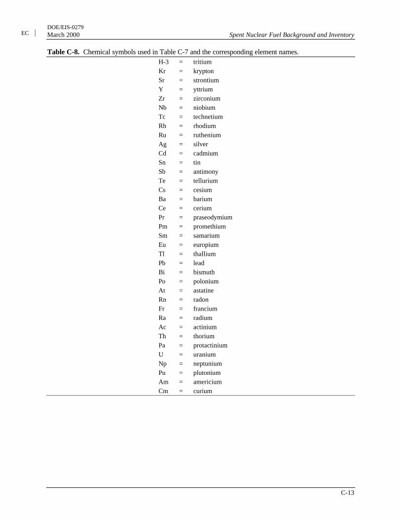
DOE/EIS-0279March 2000 Spent Nuclear Fuel Background and Inventory
C-13
Table C-8. Chemical symbols used in Table C-7 and the corresponding element names.H-3 = tritiumKr = kryptonSr = strontiumY = yttriumZr = zirconiumNb = niobiumTc = technetiumRh = rhodiumRu = rutheniumAg = silverCd = cadmiumSn = tinSb = antimonyTe = telluriumCs = cesiumBa = bariumCe = ceriumPr = praseodymiumPm = promethiumSm = samariumEu = europiumTl = thalliumPb = leadBi = bismuthPo = poloniumAt = astatineRn = radonFr = franciumRa = radiumAc = actiniumTh = thoriumPa = protactiniumU = uraniumNp = neptuniumPu = plutoniumAm = americiumCm = curium
EC

DOE/EIS-0279Spent Nuclear Fuel Background and Inventory March 2000
C-14
References
DOE (U.S. Department of Energy), 1995a, Final Programmatic Spent Nuclear Fuel Management andIdaho National Engineering Laboratory Environmental Restoration and Waste ManagementPrograms Environmental Impact Statement, DOE/EIS-0203, Idaho Operations Office, Idaho Falls,Idaho.
DOE (U.S. Department of Energy), 1995b, Final Environmental Impact Statement, Interim Managementof Nuclear Materials, DOE/EIS-0220, Savannah River Site, Aiken, South Carolina.
DOE (U.S. Department of Energy), 1996a, Final Environmental Impact Statement on a Proposed NuclearWeapons Nonproliferation Policy Concerning Research Reactor Spent Nuclear Fuel, DOE/EIS-0218F, Washington, D.C.
DOE (U.S. Department of Energy), 1996b, Technical Strategy for the Treatment, Packaging, andDisposal of Aluminum Based Spent Nuclear Fuel, A Report of the Research Reactor Spent NuclearFuel Task Team, Volume I, Washington, D.C.
Garrett, R. L., S. D. Kahook, L. R. Canas, and M. J. Beckum, 1995, “Spent Nuclear Fuel Characterizationfor a Bounding Reference Assembly for the Receiving Basin for Offsite Fuel,” Nuclear Safety, 36:2,U.S. Department of Energy Office of Scientific and Technical Information, Oak Ridge, Tennessee,July-December.

DOE/EIS-0279March 2000 Spent Nuclear Fuel Background and Inventory
C-15
cesium, 12
criticality, 1, 2
DOE, 1, 2, 3, 5, 6
F Canyon, 3
geologic repository, 3
Group A, 4, 6
Group B, 5, 7
Group C, 5, 8
Group D, 5, 8
Group E,5, 8
Group F, 5, 9
heavy metal, 1, 6
HEU,1, 5
Idaho National Engineering and Environmental
Laboratory, 2, 4, 5, 7
impacts, 2, 6
INEEL, 4, 7
LEU, iii, 1, 5
Low-enriched uranium, 1
L-Reactor Disassembly Basin, 3, 4, 7, 8, 9
Mark-18 targets, 3
Mark-42 targets, 5
plutonium, 1, 5, 12
process, 1
Receiving Basin for Offsite Fuel, 2, 3, 5,
processing, 2
Savannah River Site, iii, 2, 4,
Sodium Reactor Experiment fuel, 4
uranium, 1, 3, 4, 5, 6, 12
EC

APPENDIX D. ACCIDENT ANALYSIS


DOE/EIS-0279March 2000 Accident Analysis
D-iii
TABLE OF CONTENTS
Section Page
D.1 General Accident Information ........................................................................................... D-1D.2 Accident Analysis Method ................................................................................................ D-2
D.2.1 Technologies and Related Facilities ...................................................................... D-2D.2.2 Radiological Hazards ........................................................................................... D-4D.2.3 Chemical Hazards ................................................................................................ D-4
D.3 Impacts of Postulated Accidents Involving Radioactive Materials ...................................... D-5D.3.1 H-Canyon and FB-line ......................................................................................... D-5D.3.2 Receiving Basin for Offsite Fuel........................................................................... D-5D.3.3 Reactor Disassembly Basin .................................................................................. D-5D.3.4 Transfer and Storage Facilities ............................................................................. D-5
D.3.4.1 Transfer Facility Accidents .................................................................... D-5D.3.4.2 Dry Storage Facility Accidents............................................................... D-8
D.3.5 ElectroMetallurgical Treatment Accident Sequences ............................................. D-9D.3.6 Melt and Dilute Treatment Facility Accident Sequences........................................ D-12D.3.7 Mechanical Dilution Treatment ............................................................................ D-13
D.3.7.1 Press and Dilute Treatment Accident Sequences ..................................... D-13D.3.7.2 Chop and Dilute Treatment Accident Sequences ..................................... D-14
D.3.8 Vitrification Facilities........................................................................................... D-16D.3.8.1 Glass Material Oxidation and Dissolution System Accident Scenarios..... D-16D.3.8.2 Plasma Arc Accident Scenarios .............................................................. D-17D.3.8.3 F Canyon Dissolve and Vitrify Treatment Accident Sequences................ D-18D.3.8.4 New Dissolve and Vitrify Facility........................................................... D-20
D.4 Comparison of Accident Impacts for Alternative Facility Locations................................... D-20D.5 Impacts of Postulated Accidents Involving Nonradioactive Hazardous Materials................ D-20
D.5.1 Loss of 50-Percent Sodium Hydroxide Containment ............................................. D-19D.5.2 Loss of 50-Percent Nitric Acid Containment ......................................................... D-21D.5.3 Loss of 30-Percent Sodium Nitrite Containment.................................................... D-21D.5.4 Surface Vehicle Impact ........................................................................................ D-22
D.6 Environmental Justice....................................................................................................... D-22References ................................................................................................................................. D-23
List of Tables
Table Page
D-1 Accident frequency categories. .......................................................................................... D-2D-2 Alternatives and corresponding facilities. .......................................................................... D-3D-3 H-Canyon radiological accidents and impacts.................................................................... D-5D-4 FB-Line radiological accidents and impacts....................................................................... D-6D-5 Receiving Basin for Offsite Fuel radiological accidents and impacts .................................. D-7D-6 Reactor Disassembly Basins radiological accidents and impacts ........................................ D-7D-7 Transfer Facility radiological accidents and impacts.......................................................... D-8
EC

DOE/EIS-0279Accident Analysis March 2000
D-iv
D-8 Dry Storage radiological accidents and impacts................................................................. D-10
TABLE OF CONTENTS (Continued)
List of Tables (Continued)
Table Page
D-9 Electrometallurgical Treatment radiological accidents and impacts .................................... D-10D-10 Melt and Dilute Treatment radiological accidents and impacts ........................................... D-10D-11 Press and Dilute radiological accidents and impacts........................................................... D-14D-12 Chop and Dilute radiological accidents and impacts .......................................................... D-15D-13 GMODS radiological accidents and impacts...................................................................... D-17D-14 Plasma Arc radiological accidents and impacts.................................................................. D-19D-15 F Canyon Dissolve and Vitrify radiological accidents and impacts ..................................... D-19D-16 New Dissolve and Vitrify radiological accidents and impacts............................................. D-20

DOE/EIS-0279March 2000 Accident Analysis
D-1
APPENDIX D. ACCIDENT ANALYSIS
This appendix provides detailed information onthe management of spent nuclear fuel (SNF).The information includes potential accident sce-narios for new, modified, and existing facilitiesthat the U.S. Department of Energy (DOE)would use for each alternative. The appendixprovides estimates of the quantity and composi-tion of hazardous materials that could be releasedin an accident as well as the consequences toworkers and the public, estimated in terms ofdose and latent cancer fatalities for radiologicalreleases and of concentration levels for chemicalreleases.
The sources of information for the accidentanalyses for existing facilities are safety analysisreports and basis for interim operation docu-ments. For new or modified facilities the sourcesvary, depending on the processes involved. Ingeneral, DOE performed detailed hazard assess-ments to identify potential significant accidents,basing the determination of significance on theexistence of sufficient energy sources and haz-ardous materials that, if released, would impactworkers or the public. The following sectionsprovide specific information on the hazards as-sessments for the alternatives.
D.1 General Accident Information
An accident, as discussed in this appendix, is aninadvertent release of radiological or chemicalhazardous materials as a result of a sequence ofone or more probable events. The sequence usu-ally begins with an initiating event, such as ahuman error and explosion, or earthquake andstructural failure, followed by a succession ofother events that could be dependent or independ-ent of the initial event, which dictate the acci-dent’s progression and the extent of materialsreleased. Initiating events fall into three catego-ries:
• Internal initiators – normally originate inand around the facility but are always a re-sult of facility operations. Examples include
equipment or structural failures, human er-rors, and internal flooding.
• External initiators – are independent of fa-cility operations and normally originate fromoutside the facility. Some external initiatorsaffect the ability of the facility to maintain itsconfinement of hazardous materials becauseof potential structural damage. Examples in-clude aircraft crashes, nearby explosions,and toxic chemical releases at nearby facili-ties that affect worker performance.
• Natural phenomena initiators – are naturaloccurrences that are independent of facilityoperations and occurrences at nearby facili-ties or operations. Examples include earth-quakes, high winds, floods, lightning, andsnow. Although natural phenomena initia-tors are independent of external facilities,their occurrence can involve those facilitiesand compound the progression of the acci-dent.
The likelihood of an accident occurring and itsconsequences usually depend on the initiator andthe sequence of events and their frequencies orprobabilities. Accidents can be grouped into fourcategories—anticipated, unlikely, extremely un-likely, and not reasonably foreseeable, as listed inTable D-1.
DOE based the frequencies of accidents at exist-ing SNF management facilities on safety analysesand historical data about event occurrences. Forproposed new facilities without design details,DOE based the accident frequencies on hazardanalyses, historical data for similar facilities andoperations, and best estimates. For all facilities,DOE analyzed the bounding accident in appro-priate accident classes (e.g., natural phenomenahazards, operational errors, external events),such as the worst case fire, to represent all otheraccident in that class.
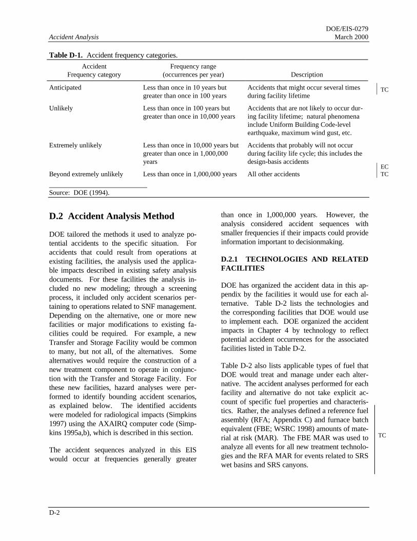
DOE/EIS-0279Accident Analysis March 2000
D-2
Table D-1. Accident frequency categories.
AccidentFrequency category
Frequency range(occurrences per year) Description
Anticipated Less than once in 10 years butgreater than once in 100 years
Accidents that might occur several timesduring facility lifetime
Unlikely Less than once in 100 years butgreater than once in 10,000 years
Accidents that are not likely to occur dur-ing facility lifetime; natural phenomenainclude Uniform Building Code-levelearthquake, maximum wind gust, etc.
Extremely unlikely Less than once in 10,000 years butgreater than once in 1,000,000years
Accidents that probably will not occurduring facility life cycle; this includes thedesign-basis accidents
Beyond extremely unlikely Less than once in 1,000,000 years All other accidents
Source: DOE (1994).
D.2 Accident Analysis Method
DOE tailored the methods it used to analyze po-tential accidents to the specific situation. Foraccidents that could result from operations atexisting facilities, the analysis used the applica-ble impacts described in existing safety analysisdocuments. For these facilities the analysis in-cluded no new modeling; through a screeningprocess, it included only accident scenarios per-taining to operations related to SNF management.Depending on the alternative, one or more newfacilities or major modifications to existing fa-cilities could be required. For example, a newTransfer and Storage Facility would be commonto many, but not all, of the alternatives. Somealternatives would require the construction of anew treatment component to operate in conjunc-tion with the Transfer and Storage Facility. Forthese new facilities, hazard analyses were per-formed to identify bounding accident scenarios,as explained below. The identified accidentswere modeled for radiological impacts (Simpkins1997) using the AXAIRQ computer code (Simp-kins 1995a,b), which is described in this section.
The accident sequences analyzed in this EISwould occur at frequencies generally greater
than once in 1,000,000 years. However, theanalysis considered accident sequences withsmaller frequencies if their impacts could provideinformation important to decisionmaking.
D.2.1 TECHNOLOGIES AND RELATEDFACILITIES
DOE has organized the accident data in this ap-pendix by the facilities it would use for each al-ternative. Table D-2 lists the technologies andthe corresponding facilities that DOE would useto implement each. DOE organized the accidentimpacts in Chapter 4 by technology to reflectpotential accident occurrences for the associatedfacilities listed in Table D-2.
Table D-2 also lists applicable types of fuel thatDOE would treat and manage under each alter-native. The accident analyses performed for eachfacility and alternative do not take explicit ac-count of specific fuel properties and characteris-tics. Rather, the analyses defined a reference fuelassembly (RFA; Appendix C) and furnace batchequivalent (FBE; WSRC 1998) amounts of mate-rial at risk (MAR). The FBE MAR was used toanalyze all events for all new treatment technolo-gies and the RFA MAR for events related to SRSwet basins and SRS canyons.
TC
ECTC
TC

DOE/EIS-0279March 2000 Accident Analysis
D-3
Table D-2. Alternatives and corresponding fa-cilities.

DOE/EIS-0279Accident Analysis March 2000
D-4
D.2.2 RADIOLOGICAL HAZARDS
The analysis used the computer code AXAIRQ tomodel accidental atmospheric radioactive re-leases from the Savannah River Site (SRS) thatare of relatively short duration. AXAIRQstrictly follows the guidance in Regulatory Guide1.145 (NRC 1982) on accidental releases, andhas been verified and validated. The release canoriginate from a vent or stack and release heightscan be from 0 to 100 meters (0 to 328 feet), asappropriate for the scenario. The code considersterrain for elevated releases. In accordance withthe regulatory guide, it considers plume meanderand fumigation under certain conditions. Plumerise due to buoyancy or momentum is not avail-able. The program uses a 5-year meteorologicaldata base for the Savannah River Site, and de-termines the shortest distance to the Site bound-ary in each of the 16 sectors by determining thedistance to one of 875 locations along the bound-ary. The code uses the shortest distance in eachsector to calculate the concentration for that sec-tor. DOE used PRIMUS, which was developedby the Oak Ridge National Laboratory, to con-sider decay and daughter ingrowth.
The analysis assumes that all tritium releasedwould have the form of tritium oxide and, fol-lowing International Commission on RadiologicalProtection methodology, the dose conversionfactor for tritium has been increased by 50 per-cent to account for absorption through the skin.For population dose calculations, age-specificbreathing rates are applied, but adult dose con-version factors are used. Radiation doses werecalculated to the maximally exposed offsite indi-vidual (MEI), to the population within 50 milesof the facility, and to an uninvolved worker as-sumed to be 640 meters (2,100 feet) downwind ofthe facility.
After DOE calculated the total radiation dose tothe public, it used dose-to-risk conversion factorsestablished by the National Council on RadiationProtection and Measurements (NCRP) to esti-mate the number of latent cancer fatalities thatcould result from the calculated exposure. Nodata indicate that small radiation doses cause
cancer; however, to be conservative the NCRPassumes that any amount of radiation has somerisk of inducing cancer. DOE has adopted theNCRP factors of 0.0005 latent cancer fatality foreach person-rem of radiation exposure to thegeneral public and 0.0004 latent cancer fatalityfor each person-rem of radiation exposure to ra-diation workers (NCRP 1993).
D.2.3 CHEMICAL HAZARDS
For chemically toxic materials, the long-termhealth consequences of human exposure to haz-ardous materials are not as well understood asthose related to radiation exposure. A determi-nation of potential health effects from exposuresto chemically hazardous materials, compared toradiation, is more subjective. Therefore, the con-sequences from accidents involving hazardousmaterials are expressed in terms of airborne con-centrations at various distances from the accidentlocation, rather than in terms of specific healtheffects.
To determine the potential health effects to work-ers and the public that could result from acci-dents involving hazardous materials, the airborneconcentrations of such materials released duringan accident at varying distances from the point ofrelease were compared to the Emergency Re-sponse Planning Guideline (ERPG) values(AIHA 1991). The American Industrial HygieneAssociation established these values, which de-pend on the chemical substance, for the followinggeneral severity levels to ensure that the neces-sary emergency actions occur to minimize expo-sures to humans.
• ERPG-1 Values. Exposure to airborne con-centrations greater than ERPG-1 values for aperiod greater than 1 hour results in an unac-ceptable likelihood that a person would expe-rience mild transient adverse health effects orperception of a clearly defined objectionableodor.
• ERPG-2 Values. Exposures to airborne con-centrations greater than ERPG-2 values for aperiod greater than 1 hour results in an unac-

DOE/EIS-0279March 2000 Accident Analysis
D-5
ceptable likelihood that a person would expe-rience or develop irreversible or other serioushealth effects or symptoms that could impaira person’s ability to take protective action.
• ERPG-3 Values. Exposure to airborne con-centrations greater than ERPG-3 values for aperiod greater than 1 hour results in an unac-ceptable likelihood that a person would expe-rience or develop life-threatening healtheffects.
Not all hazardous materials have ERPG values.For chemicals that do not have ERPG values, acomparison was made to the most restrictiveavailable exposure limits established by otherguidelines to control worker accidental exposuresto hazardous materials. In this document, theERPG-2 equivalent that is used is the PEL-TWA(Permissible Exposure Limit – Time WeightedAverage) from 29 CFR Part 1910.1000, Subpart Z.
D.3 Impacts of Postulated Acci-dents Involving Radioactive Mate-rials
These sections describe the potential accidentsand risks associated with the operation of eachfacility that may be utilized in the implementationof a technology. The impacts of each technologyare shown in Sections D.3.5 to D.3.8. The mate-rial at risk in all treatments is the same, only therelease fractions change. For these cases, over95 percent of the calculated doses come from therelease of plutonium-240 and curium-244. Theonly exception to this are criticality accident sce-narios when over 99 percent of the dose comesfrom the release of ruthenium-106.
D.3.1 H-CANYON AND FB-LINE
Tables D-3 and D-4 summarize potential acci-dents and their impacts for the H-Canyon andFB-Line facilities, respectively (WSRC 1993,1995; TtNUS 1999b).
D.3.2 RECEIVING BASIN FOR OFFSITEFUEL
Potential accidents and their impacts for the Re-ceiving Basin for Offsite Fuel (RBOF) facilityhave been documented in a safety analysis report(WSRC 1997a). Table D-5 lists the accidentswith the highest risks and consequences.
D.3.3 REACTOR DISASSEMBLY BASIN
Potential accidents and their impacts for the L-Reactor Disassembly Basin have been docu-mented in a basis for interim operation report(WSRC 1997b). Table D-6 summarizes the re-sults.
D.3.4 TRANSFER AND STORAGE FACI-LITIES
DOE could collocate the transfer and storagefacilities either in separate buildings or in a singlebuilding. The accident impacts associated withthe operation of these facilities apply to bothcases and assume the location of the facilities inL-Area.
D.3.4.1 Transfer Facility Accidents
Radioactive Material Leaks From Shipping orStorage Cask (TS-1)
Radioactive materials could leak from shippingor storage casks. In this accident sequence, ra-dioactive material would leak to the surface ofthe shipping or storage cask and a small amountwould become airborne. The principal radionu-clides would be cesium-137, cerium-144, ruthe-nium-106, and strontium-90. The total curiesreleased in this scenario would 1.0×10⁻⁷ andwould result in negligible consequences. Thisevent is postulated to occur once in 10 years ofoperation. The calculated consequences for thisscenario are listed in Table D-7.
Table D-3. H-Canyon radiological accidents and impacts.a
Accident consequences
TC
TC

DOE/EIS-0279Accident Analysis March 2000
D-6
Accident
Maximumcuries
releasedAccidentfrequency
Noninvolvedworker(rem)
MEIb
(rem)
Offsitepopulation
(person-rem)Latent cancer
fatalities
Ruthenium volatilization 140 Once in11 years
0.13 0.013 770 0.39
Fire 0.57 Once in1,600 years
0.53 0.055 3,300 1.6
Earthquake 860 Once in5,000 years
1.8 0.246 14,000 7.0
Coil and tube, cooling towercirculated
13 Once in14,000 years
13 1.3 78,000 39
Transfer error to Building 211-H 3,700 Once in14,000 years
1.5 0.16 9,200 4.6
Hydrogen deflagration 1.1 Once in18,000 years
1.0 0.11 6,400 3.2
Criticality 47,000 Once in77,000 years
0.029 0.0012 18 0.009
a. Source: TtNUS (1999b).b. MEI = Maximally exposed individual.
Table D-4. FB-Line radiological accidents and impacts.Accident Consequences
Accident
Maximumcuries
releasedAccidentfrequency
Noninvolvedworker(rem)
MEIa
(rem)
Offsitepopulation
(person-rem)Latent cancer
fatalities
Design basis earthquake,0.2g intensityb
0.31 Once in5,000 years
0.34 0.042 150 0.077
Propagated firec 2.2 Once in 59,000years
0.18 0.14 1,100 0.53
a. MEI = Maximally exposed individual.b. Source: WSRC (1993).c. Source: WSRC (1995).
Cask Decontamination Waste Released to En-vironment (TS-3)
Casks would be washed at receipt and beforeshipping. The wash liquid probably would becollected in a sump or storage tank and releasedto the environment if sample results showedcontamination levels to be within acceptable lim-its. Excessively radioactive or hazardous mate-rial could be pumped inadvertently to an outfallrather than to the liquid radioactive waste
system or hazardous waste storage if there wasan error in processing samples or reading labo-ratory test results. This scenario assumes thathappens and a small amount becomes airborne.The total curies released to air would be 2.0×10⁻⁷
and would result in negligible consequences.This event is postulated to occur once in 100years of operation. The calculated consequencesfor this scenario are listed in Table D-7.
EC
TC

DOE/EIS-0279March 2000 Accident Analysis
D-7
Table D-5. Receiving Basin for Offsite Fuel radiological accidents and impacts.a
Accident Consequences
Accident
Maximumcuries
releasedAccidentfrequency
Noninvolvedworker(rem)
MEIb
(rem)
Offsitepopulation
(person-rem)Latent cancer
fatalities
Fuel rupture 160,000 Once in1.4 years
0.0018 1.9×10⁻⁴ 10 0.005
Resin explosion 1.0 Once in400 years
0.0012 1.3×10⁻⁴ 7.8 0.0039
Uncontrolled chemical reaction 1,600,000 Once in450 years
0.018 0.0019 100 0.05
Resin fire 11 Once in1,200 years
1.3×10⁻⁴ 1.4×10⁻⁵ 0.83 4.2×10⁻⁴
Process-induced criticality 4,800 Once in1,500 years
0.16 0.016 970 0.49
NPHd (high winds)Fuel breach 1,600,000 Once in
2,600 years0.13 0.0024 130 0.063
Criticality 48,000 Once in26,000 years
13 0.22 12,000 6.2
NPH (earthquake)Waste tank breach 0.69 Once in
280 years0.0065 1.1×10⁻⁴ 6.3 3.2×10⁻³
Fuel breach 1,600,000 Once in36,000,000
years
0.13 0.0024 130 0.063
Criticality 48,000 Once in38,000,000
years
13 0.22 12,000 6.2
a. Source: TtNUS (1999a).b. MEI = Maximally exposed individual.c. Data not available.d. NPH = Natural Phenomenon Hazard.
Table D-6. Reactor Disassembly Basins radiological accidents and impacts.a
Accident Consequences
Accident
Maximumcuries
releasedAccident fre-
quency
Noninvolvedworker(rem)
MEIb
(rem)
Offsitepopulation
(person-rem)Latent cancer
fatalities
Basin overfill (c) Once in100 years
0 4.6×10⁻⁴ (c)
Mishandling fuel assembly (c) Once in100 years
25 0 0 0
Criticality 4,800 Once in300 years
0.16 0.016 660 0.3
Basin water draindown (c) Once in500 years
0.055 0.016 (c)
a. Source: WSRC (1997b), TtNUS (1999a).b. MEI = Maximally exposed individual.c. Accidents expected to result in low consequences and risks to the onsite worker population and the offsite population.
Quantitative estimates of consequences and risks are not available.
TC
TC
TC

DOE/EIS-0279Accident Analysis March 2000
D-8
Table D-7. Transfer Facility radiological accidents and impacts.a
Accident Consequences
Accident
Maximumcuries
releasedAccidentfrequency
Noninvolvedworker(rem)
MEIb
(rem)
Offsitepopulation
(person-rem)Latent cancer
fatalities
Railroad car contamination, TS-1 1.0×10⁻⁷ Once in10 years
1.7×10⁻⁷ 1.8×10⁻⁸ 7.4×10⁻⁴ 3.7×10⁻⁷
Sump Release, TS-3 2.1×10⁻⁷ Once in100 years
3.5×10⁻⁷ 3.6×10⁻⁸ 1.5×10⁻³ 7.4×10⁻⁷
a. Source: TtNUS (1999a).b. MEI = Maximally exposed individual.
Cask Criticality From Internal Disruption -Single Shipping Cask (TS-4)
Shipping casks containing spent fuel would bemoved between facilities by rail or truck andloaded or unloaded from transports using over-head or mobile cranes. The casks contain inter-nal structures that maintain fuel separation orprovide neutron absorption. Casks certified inaccordance with regulations of the U.S. Depart-ment of Transportation are designed to withstanddrops from a specified height. However, if thecask internal structures were not assembledproperly, disruption and redistribution of the fuelcould occur. In addition, the fuel itself could bedamaged or loose its integrity and redistributeitself in a critical configuration. This could pro-duce a criticality at the time of the disruption orlater if the cask were filled with water for purg-ing. If this event occurred outdoors, the releasewould not be filtered. This event is not credible.
Criticality From Fuel Dropped On To FloorOr In To Dry Storage Rack (TS-5)
A criticality accident could result if spent nuclearfuel were dropped in a pile on the floor ordropped into the cask-unloading dry storage rack.The fuel drop could result from operator error orequipment failure in the handling ma-chine orspent fuel structure. Double contingency protec-tion would require the dropping of at least twospent fuel loads (assemblies, canisters, bundles,etc.) before a criticality occurred. In addition,the first drop would have to be unrecovered whenthe second drop occurred. Procedures wouldrequire the recovery of the first fuel dropped be-
fore material movement could resume. The ef-fects of a criticality event would be mitigated byshielding and the physical distance of the opera-tors in remote handling operations. This eventwould occur inside the facility, so released radio-nuclides would be filtered. This event is not con-sidered credible.
Criticality of Spent Fuel in Several AdjacentShipping Casks (TS-7)
This event addresses a criticality accident amongspent nuclear fuel brought together in multipleshipping or storage casks. Because the nuclearreaction would occur in all the fuel in the array,several casks could be involved. A criticalityaccident of this nature would produce a directradiation hazard and would release radioactivecontamination if one or more casks werebreached. However, a criticality during cask drystorage is not a credible event.
D.3.4.2 Dry Storage Facility Accidents
Spent Nuclear Fuel Dry Storage Process-Related Criticality Accident (SLS-2)
This accident scenario involves criticality result-ing from the improper loading of dry storageracks or the mechanical failure of racks. Me-chanical failure or collapse could result from acrane impact or structural flaw in the racks. Im-proper loading would result in sufficient spentnuclear fuel assemblies placed near one anotherwith insufficient neutron absorbers to prevent acriticality. A collapse of the racks would resultin sufficient spent fuel assemblies piled near one
TC
TC
TC

DOE/EIS-0279March 2000 Accident Analysis
D-9
another in the debris with insufficient neutronabsorbers to prevent a criticality. This event ispostulated to occur once in 330 years of opera-tion. The calculated consequences for this sce-nario are listed in Table D-8.
Natural Phenomenon Hazard-Induced SpentNuclear Fuel Dry Storage Criticality Accident(SLS-3)
This accident scenario involves a natural phe-nomenon hazard-induced criticality resultingfrom an earthquake-induced mechanical failureof racks (e.g., collapse or crane impact and col-lapse) or a subsequent fission product releaseresulting from a fuel breach. This event is predi-cated on the assumption that the facility couldwithstand an earthquake intact and operational.However, the scenario assumes that the structurethat contains the material at risk fails, resulting inthe event. This event is postulated to occur oncein 2,000 years of operation. The calculated con-sequences for this scenario are listed in Table D-8.
Spent Nuclear Fuel Dry Storage Fission Prod-uct Release (SLS-1)
This accident scenario involves the release offission products from a fuel breach and a simul-taneous loss of confinement due to an earth-quake. The fuel breach would result from anearthquake-induced mechanical failure or col-lapse of the storage racks or an earthquake-induced crane impact. This event is postulated tooccur once in 2,000 years of operation. The cal-culated consequences for this scenario are listedin Table D-8.
D.3.5 ELECTROMETALLURGICALTREATMENT ACCIDENT SEQUENCES
Melter Eruption (GFP-1 and MM-1)
The electrometallurgical technology would havetwo separate melters. The melter eruption pos-tulated event could result from impurities in theglass melt (GFP-1) or the metal melt (MM-1).
Impurities could range from water that couldcause a steam eruption to chemical contaminantsthat could react at elevated temperatures andproduce a highly exothermic reaction (eruption ordeflagration). The scenario assumes that the re-sulting sudden pressure increase would eject thefissile-material-bearing melt liquid into the proc-essing structure. It also assumes that the energyrelease would not damage the processing struc-ture and its associated filtered exhaust ventilationsystem. The melter ventilation systems wouldremove or dilute explosive mixtures that couldbuild up in the gas space above the molten mate-rial. Operating procedures and verificationswould prevent the addition of impure or incorrectmaterials to the melt. Therefore, this event ispostulated to occur once in 20 years of operation.
If the eruption was large, operating personnelwould hear and see it. A small eruption might bedetected only by airborne radiation monitors be-cause the remotely-operated melters would be ina heavily shielded area. The effects of the erup-tion would be mitigated by the melter design,which would include venting methods to respondto an over-pressure event. The melter buildingstructure and the ventilation system would con-fine particulate radioactive material released inthe eruption. The calculated consequences forthis scenario are listed in Table D-9 for the mol-ten glass release and Table D-10 for the moltenmetal spill. Noble gases and tritium released onthe event would not be filtered.
Earthquake-Induced Fission Product Releaseand Confinement Failure (GFP-4 and MM-5)
The fission-product-release scenario involvesdamage to the melter structure and its associatedsystems that would release fission products. Thisevent assumes that the facility would withstandan earthquake and remain operational. However,it also assumes that the structure that containsthe material at risk would fail, resulting in theevent. This event is postulated to occur once in2,000 years of operation. The calculated
TC
TC
TC
TC
EC

DOE/EIS-0279Accident Analysis March 2000
D-10
Table D-8. Dry Storage radiological accidents and impacts.a
Accident Consequences
Accident
Maximumcuries
releasedAccidentfrequency
Noninvolvedworker(rem)
MEIb
(rem)
Offsitepopulation
(person-rem)Latent cancer
fatalities
Criticality in storage, SLS-2 4,800 Once in330 years
0.16 0.016 660 0.3
Earthquake-induced criticality,SLS-3
48,000 Once in2,000 years
13 0.22 12,000 6.2
Fuel breach during earthquake,SLS-1
1,100,000 Once in2,000 years
0.014 0.0015 54.1 0.027
a. Source: TtNUS (1999a).b. MEI = Maximally expose individual.
Table D-9. Electrometallurgical Treatment radiological accidents and impacts (glass melter only).a
Accident Consequences
Accident
Maximumcuries
releasedAccidentfrequency
Noninvolvedworker(rem)
MEIb
(rem)
Offsitepopulation
(person-rem)Latent cancer
fatalities
Melter eruption, GFP-1 1,200 Once in20 years
1.6×10⁻⁵ 1.1×10⁻⁶ 0.04 2.0×10⁻⁵
Earthquake-induced fission prod-uct release and confinementfailure, GFP-4
2,300 Once in2,000 years
3.2×10⁻⁵ 2.2×10⁻⁶ 0.08 4.0×10⁻⁵
Melter eruption with loss of ven-tilation, GFP-1a
1,200 Once in2,000 years
0.002 2.3×10⁻⁴ 9.5 0.0047
Earthquake spill with loss of ven-tilation, GFP-4a
2,300 Once in200,000 years
0.038 6.2×10⁻⁴ 26 0.013
a. Source: TtNUS (1999a).b. MEI = Maximally exposed individual.
Table D-10. Melt and Dilute Treatment radiological accidents and impacts (these accidents also apply tothe metal melter for Electrometallurgical Treatment).a
Accident Consequences
Accident
Maximumcuries
releasedAccidentfrequency
Noninvolvedworker(rem)
MEIb
(rem)
Offsitepopulation
(person-rem)Latent cancer
fatalities
Melter eruption, MM-1 0.09 Once in20 years
7.1×10⁻⁶ 7.4×10⁻⁷ 0.03 1.5×10⁻⁵
Criticality due to multiple batching5×1017 fissions, MM-4
4,700 Once in330 years
0.004 4.8×10⁻⁵ 1.6 0.0008
Earthquake-induced fission prod-uct release and confinementfailure, MM-5
2,300 Once in2,000 years
6.8×10⁻⁵ 5.9×10⁻⁶ 0.23 1.2×10⁻⁴
Melter eruption with loss of ven-tilation, MM-1a
9,200 Once in2,000 years
0.71 0.074 3,000 1.5
Process criticality with loss ofventilation, MM-4a
14,000 Once in33,000 years
0.71 0.074 3,000 1.5
Earthquake-induced spill with lossof ventilation, MM-5a
21,000 Once in200,000 years
30 0.50 21,000 10
a. Source: TtNUS (1999a), TtNUS (2000).
TC
TC
TC

DOE/EIS-0279March 2000 Accident Analysis
D-11
b. MEI = Maximally exposed individual.
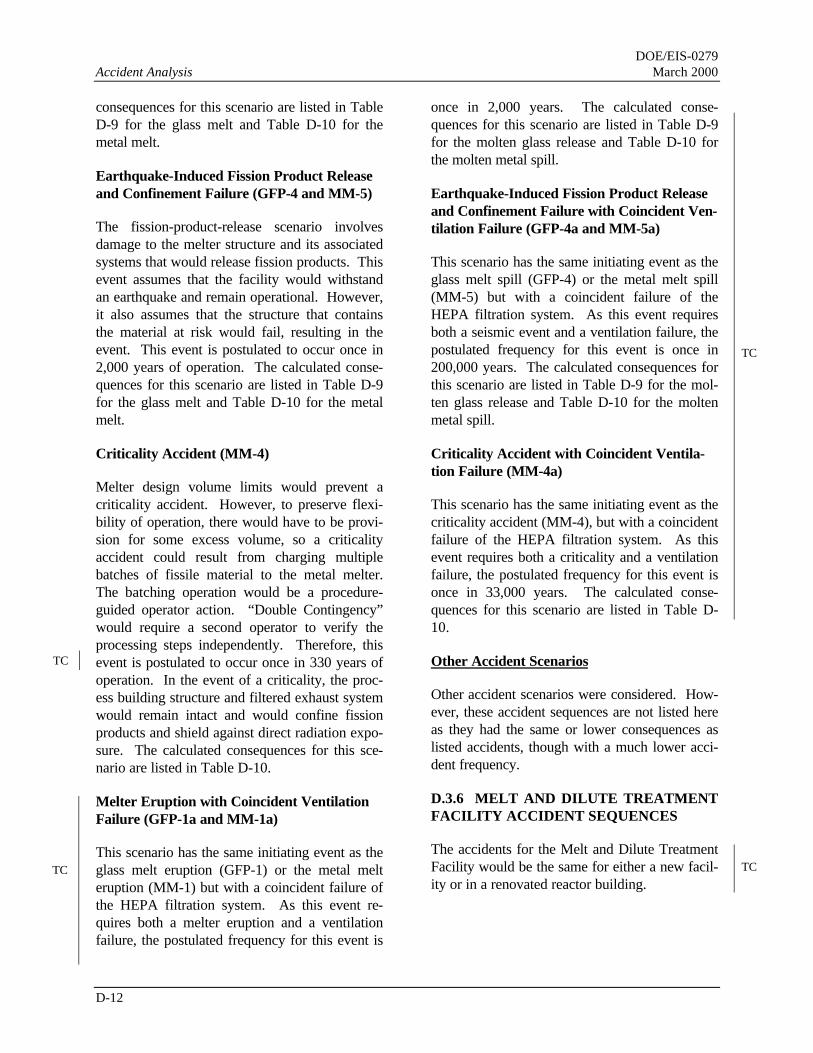
DOE/EIS-0279Accident Analysis March 2000
D-12
consequences for this scenario are listed in TableD-9 for the glass melt and Table D-10 for themetal melt.
Earthquake-Induced Fission Product Releaseand Confinement Failure (GFP-4 and MM-5)
The fission-product-release scenario involvesdamage to the melter structure and its associatedsystems that would release fission products. Thisevent assumes that the facility would withstandan earthquake and remain operational. However,it also assumes that the structure that containsthe material at risk would fail, resulting in theevent. This event is postulated to occur once in2,000 years of operation. The calculated conse-quences for this scenario are listed in Table D-9for the glass melt and Table D-10 for the metalmelt.
Criticality Accident (MM-4)
Melter design volume limits would prevent acriticality accident. However, to preserve flexi-bility of operation, there would have to be provi-sion for some excess volume, so a criticalityaccident could result from charging multiplebatches of fissile material to the metal melter.The batching operation would be a procedure-guided operator action. “Double Contingency”would require a second operator to verify theprocessing steps independently. Therefore, thisevent is postulated to occur once in 330 years ofoperation. In the event of a criticality, the proc-ess building structure and filtered exhaust systemwould remain intact and would confine fissionproducts and shield against direct radiation expo-sure. The calculated consequences for this sce-nario are listed in Table D-10.
Melter Eruption with Coincident VentilationFailure (GFP-1a and MM-1a)
This scenario has the same initiating event as theglass melt eruption (GFP-1) or the metal melteruption (MM-1) but with a coincident failure ofthe HEPA filtration system. As this event re-quires both a melter eruption and a ventilationfailure, the postulated frequency for this event is
once in 2,000 years. The calculated conse-quences for this scenario are listed in Table D-9for the molten glass release and Table D-10 forthe molten metal spill.
Earthquake-Induced Fission Product Releaseand Confinement Failure with Coincident Ven-tilation Failure (GFP-4a and MM-5a)
This scenario has the same initiating event as theglass melt spill (GFP-4) or the metal melt spill(MM-5) but with a coincident failure of theHEPA filtration system. As this event requiresboth a seismic event and a ventilation failure, thepostulated frequency for this event is once in200,000 years. The calculated consequences forthis scenario are listed in Table D-9 for the mol-ten glass release and Table D-10 for the moltenmetal spill.
Criticality Accident with Coincident Ventila-tion Failure (MM-4a)
This scenario has the same initiating event as thecriticality accident (MM-4), but with a coincidentfailure of the HEPA filtration system. As thisevent requires both a criticality and a ventilationfailure, the postulated frequency for this event isonce in 33,000 years. The calculated conse-quences for this scenario are listed in Table D-10.
Other Accident Scenarios
Other accident scenarios were considered. How-ever, these accident sequences are not listed hereas they had the same or lower consequences aslisted accidents, though with a much lower acci-dent frequency.
D.3.6 MELT AND DILUTE TREATMENTFACILITY ACCIDENT SEQUENCES
The accidents for the Melt and Dilute TreatmentFacility would be the same for either a new facil-ity or in a renovated reactor building.
TC
TC
TC
TC

DOE/EIS-0279March 2000 Accident Analysis
D-13
Melter Eruption (MM-1)
This event would be identical to the metal melteruption described as MM-1 in D.3.5. The cal-culated consequences are presented in Ta-ble D-10.
Criticality Accident (MM-4)
The criticality event would be identical to thatdescribed for the metal melter as MM-4 in D.3.5.The calculated consequences are presented inTable D-10.
Earthquake-Induced Fission Product Releaseand Confinement Failure (MM-5)
The fission product release and confinement fail-ure would be identical to that described as MM-5in D.3.5 The calculated consequences are pre-sented in Table D-10.
Melter Eruption with Ventilation Failure(MM-1a)
This event would be identical to the metal melteruption with ventilation failure described inD.3.5. The calculated consequences are pre-sented in Table D-10.
Earthquake-Induced Fission Product Releaseand Confinement Failure with Coincident Ven-tilation Failure (MM-5a)
This event would be identical to the Earthquake-induced spill with ventilation failure described inD.3.5. The calculated consequences are pre-sented in Table D-10.
Criticality Accident with Coincident Ventila-tion Failure (MM-4a)
This event would be identical to the DoubleBatching Criticality with ventilation failure de-scribed in D.3.5. The calculated consequencesare presented in Table D-10.
Other Accident Scenarios
Other accident scenarios were considered. How-ever, these accident sequences are not listed hereas they had the same or lower consequences aslisted accidents, though with a much lower acci-dent frequency.
D.3.7 MECHANICAL DILUTIONTREATMENT
D.3.7.1 Press and Dilute Treatment AccidentSequences
Fission Product Release (SDP-2)
This event assumes that the facility would with-stand an earthquake and remain operational.However, it also assumes that the structure thatcontains the material at risk would fail, resultingin the event. This event is postulated to occuronce in 2,000 years of operation. The calculatedconsequences for this scenario are listed in TableD-11.
Spent Nuclear Fuel-Depleted Uranium PressProcess Criticality Accident (SDP-3)
This process-related criticality would result frommultiple batches of spent fuel plates introducedinto the press or an inadvertent substitution ofspent fuel plates for depleted uranium plates. Ineither instance sufficient spent fuel in the con-figuration would result in a criticality. Thisevent is postulated to occur once in 330 years ofoperation. The calculated consequences for thisscenario are listed in Table D-11.
Earthquake-Induced Fire/Pyrophoric Reaction(SDP-4)
An earthquake-induced fire or pyrophoric reac-tion would result from friction due to mechanicalshredding, electrical or mechanically inducedfires on uranium metal fuel, or a fire started by ahydraulic fluid leak that resulted in a subsequentpyrophoric reaction. This event assumes that thefacility would withstand an earthquake and re-main operational. However, it also assumes that
TC
TC
TC
TC
TC
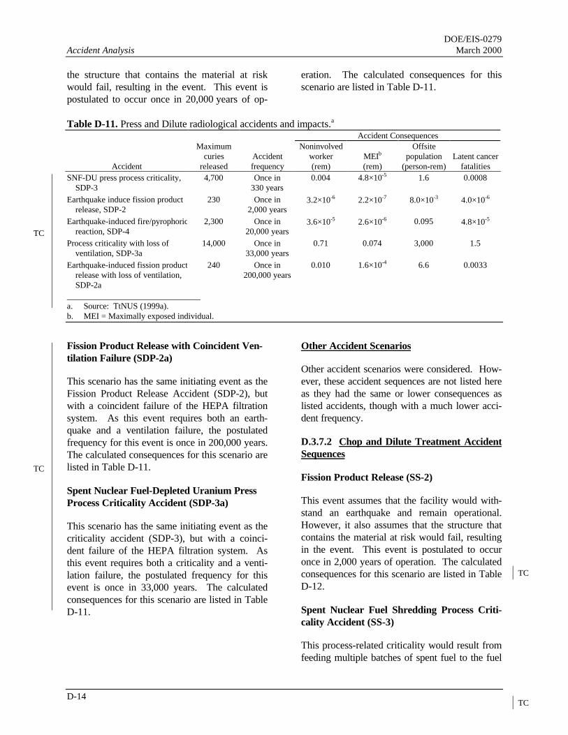
DOE/EIS-0279Accident Analysis March 2000
D-14
the structure that contains the material at riskwould fail, resulting in the event. This event ispostulated to occur once in 20,000 years of op-
eration. The calculated consequences for thisscenario are listed in Table D-11.
Table D-11. Press and Dilute radiological accidents and impacts.a
Accident Consequences
Accident
Maximumcuries
releasedAccidentfrequency
Noninvolvedworker(rem)
MEIb
(rem)
Offsitepopulation
(person-rem)Latent cancer
fatalitiesSNF-DU press process criticality,
SDP-34,700 Once in
330 years0.004 4.8×10⁻⁵ 1.6 0.0008
Earthquake induce fission productrelease, SDP-2
230 Once in2,000 years
3.2×10⁻⁶ 2.2×10⁻⁷ 8.0×10⁻³ 4.0×10⁻⁶
Earthquake-induced fire/pyrophoricreaction, SDP-4
2,300 Once in20,000 years
3.6×10⁻⁵ 2.6×10⁻⁶ 0.095 4.8×10⁻⁵
Process criticality with loss ofventilation, SDP-3a
14,000 Once in33,000 years
0.71 0.074 3,000 1.5
Earthquake-induced fission productrelease with loss of ventilation,SDP-2a
240 Once in200,000 years
0.010 1.6×10⁻⁴ 6.6 0.0033
a. Source: TtNUS (1999a).b. MEI = Maximally exposed individual.
Fission Product Release with Coincident Ven-tilation Failure (SDP-2a)
This scenario has the same initiating event as theFission Product Release Accident (SDP-2), butwith a coincident failure of the HEPA filtrationsystem. As this event requires both an earth-quake and a ventilation failure, the postulatedfrequency for this event is once in 200,000 years.The calculated consequences for this scenario arelisted in Table D-11.
Spent Nuclear Fuel-Depleted Uranium PressProcess Criticality Accident (SDP-3a)
This scenario has the same initiating event as thecriticality accident (SDP-3), but with a coinci-dent failure of the HEPA filtration system. Asthis event requires both a criticality and a venti-lation failure, the postulated frequency for thisevent is once in 33,000 years. The calculatedconsequences for this scenario are listed in TableD-11.
Other Accident Scenarios
Other accident scenarios were considered. How-ever, these accident sequences are not listed hereas they had the same or lower consequences aslisted accidents, though with a much lower acci-dent frequency.
D.3.7.2 Chop and Dilute Treatment AccidentSequences
Fission Product Release (SS-2)
This event assumes that the facility would with-stand an earthquake and remain operational.However, it also assumes that the structure thatcontains the material at risk would fail, resultingin the event. This event is postulated to occuronce in 2,000 years of operation. The calculatedconsequences for this scenario are listed in TableD-12.
Spent Nuclear Fuel Shredding Process Criti-cality Accident (SS-3)
This process-related criticality would result fromfeeding multiple batches of spent fuel to the fuel
TC
TC
TC
TC

DOE/EIS-0279March 2000 Accident Analysis
D-15
shredder. This would result in sufficient spentfuel in a configuration that could result in a criti-cality. This event is postulated to occur once in330 years of operation. The calculated conse-quences for this scenario are listed in Table D-12.
Earthquake-Induced Fire/Pyrophoric Reaction(SS-4)
An earthquake-induced fire or pyrophoric reac-tion could result from friction due to mechanical
Table D-12. Chop and Dilute radiological accidents and impacts.a
Accident Consequences
Accident
Maximumcuries
releasedAccident fre-
quency
Noninvolvedworker(rem)
MEIb
(rem)
Offsitepopulation
(person-rem)Latent cancer
fatalitiesProcess criticality, SS-3 4,700 Once in
330 years0.004 4.8×10⁻⁵ 1.6 0.0008
Earthquake-induced fission prod-uct release, SS-2
0.07 Once in2,000 years
1.2×10⁻⁷ 1.2×10⁻⁸ 4.9×10⁻⁴ 2.5×10⁻⁷
Earthquake-induced fire, SS-4 2.3 Once in2,000 years
3.6×10⁻⁶ 3.8×10⁻⁷ 0.015 7.7×10⁻⁶
Process criticality with loss ofventilation, SS-3a
14,000 Once in33,000 years
0.71 0.074 3,000 1.5
Earthquake release with loss ofventilation, SS-2a
66 Once in200,000 years
0.012 0.0012 49 0.024
Earthquake-induced fire with lossof ventilation, SS-4a
2,100 Once in200,000 years
3 0.050 2,100 1.0
a. Source: TtNUS (1999a).b. MEI = Maximally exposed individual.
shredding, electrical or mechanically inducedfires on uranium metal fuel, or a fire started by ahydraulic fluid leak that resulted in a subsequentpyrophoric reaction. This event assumes that thefacility would withstand an earthquake and re-main operational. However, it also assumes thatthe structure that contains the material at riskwould fail, resulting in the event. This event ispostulated to occur once in 2,000 years of opera-tion. The calculated consequences for this sce-nario are listed in Table D-12.
Fission Product Release with Coincident Ven-tilation Failure (SS-2a)
This scenario has the same initiating event as theFission Product Release Accident (SS-2), butwith a coincident failure of the HEPA filtrationsystem. As this event requires both an earth-quake and a ventilation failure, the postulatedfrequency for this event is once in 200,000 years.The calculated consequences for this scenario arelisted in Table D-12.
Spent Nuclear Fuel Shredding Process Criti-cality Accident (SS-3a)
This scenario has the same initiating event as thecriticality accident (SS-3), but with a coincidentfailure of the HEPA filtration system.
TC
TC
TC

DOE/EIS-0279Accident Analysis March 2000
D-16
As this event requires both a criticality and aventilation failure, the postulated frequency forthis event is once in 33,000 years. The calcu-lated consequences for this scenario are listed inTable D-12.
Other Accident Scenarios
Other accident scenarios were considered. How-ever, these accident sequences are not listed hereas they had the same or lower consequences aslisted accidents, though with a much lower acci-dent frequency.
D.3.8 VITRIFICATION FACILITIES
D.3.8.1 Glass Material Oxidation and Dissolu-tion System Accident Scenarios
Melter Eruption (GMF-1)
The postulated melter eruption could result fromimpurities in the metal melt. Impurities couldrange from water that could cause a steam erup-tion to chemical contaminants that could react atelevated temperatures and produce a highly exo-thermic reaction (eruption or deflagration). Thisscenario assumes that the resulting sudden pres-sure increase would eject the fissile-material-bearing melt liquid into the processing structure.It also assumes that the energy release would notdamage the processing structure and its associ-ated filtered exhaust ventilation system. Themelter offgas and inerting systems would removeor dilute explosive mixtures that might build upin the gas space above the molten material. Op-erating procedures and verifications prevent theaddition of impure or incorrect materials to themelt. Therefore, this event is postulated to occuronce in 20 years of operation.
If a large eruption did occur, the appearance andsound would alert operating personnel. A smalleruption might be detected only by airborne ra-diation monitors because the remotely operatedmelters would be in a heavily shielded area. Theeffects of the eruption would be mitigated by thedesign of the melter, which would include ventingmethods to respond to an over-pressure event.
The melter building structure and the ventilationsystem would confine particulate radioactivematerial released in the eruption. The calculatedconsequences for this scenario are listed in TableD-13.
Criticality Accident (GMF-4)
Melter design volume limits would prevent acriticality accident. However, to preserve flexi-bility of operation, there would have to be pro-

DOE/EIS-0279March 2000 Accident Analysis
D-17
vision for some excess volume, a criticality acci-dent could result from charging multiple batchesof fissile material to the metal melter. Thebatching operation would be a procedure-guidedoperator action. “Double Contingency” wouldrequire a second operator to verify the processingsteps independently. Therefore, this event ispostulated to occur once in 33,000 years of op-eration. In the event of a criticality, the processbuilding structure and filtered exhaust systemwould remain intact and would confine fissionproducts and shield against direct radiation expo-sure. The calculated consequences for this sce-nario are listed in Table D-13.
Earthquake-Induced Fission Product Releaseand Confinement Failure (GMF-5)
The fission-product-release scenario involvesdamage to the melter structure and its associatedsystems that would release fission products. Thisevent assumes that the facility would withstandan earthquake and remain operational. However,it also assumes that the structure that containsthe material at risk would to fail, resulting in therelease. This event is postulated to occur once in2,000 years of operation. The calculated conse-quences for this scenario are listed in Table D-13.
Table D-13. GMODS radiological accidents and impacts.a
Accident Consequences
Accident
Maximumcuries
releasedAccidentfrequency
Noninvolvedworker(rem)
MEIb
(rem)
Offsitepopulation
(person-rem)Latent cancer
fatalitiesMelter eruption, GMF-1 1,200 Once in
20 years1.6×10-5 1.1×10⁻⁶ 0.04 2.0×10⁻⁵
Criticality due to multiple batching5×1017 fissions, GMF-4
4,700 Once in330 years
0.004 4.8×10⁻⁵ 1.6 0.0008
Earthquake-induced fission prod-uct release and confinementfailure, GMF-5
2,300 Once in2,000 years
3.3×10⁻⁵ 2.2×10⁻⁶ 0.08 4.0×10⁻⁵
Melter eruption with loss of ven-tilation, GMF-1a
1,200 Once in2,000 years
0.0024 2.6×10⁻⁴ 10 0.0052
Process criticality with loss ofventilation, GMF-4a
14,000 Once in33,000 years
0.71 0.074 3,000 1.5
Earthquake-induced release withloss of ventilation, GMF-5a
2,300 Once in200,000 years
0.041 6.8×10⁻⁴ 28 0.014
a. Source: TtNUS (1999a).b. MEI = Maximally exposed individual.
Melter Eruption with Coincident VentilationFailure (GMF-1a)
This scenario has the same initiating event as themelter eruption (GMF-1), but with a coincidentfailure of the HEPA filtration system. As thisevent requires both a melter eruption and a ven-tilation failure, the postulated frequency for thisevent is once in 2,000 years. The calculated con-sequences for this scenario are listed in Table D-13.
Earthquake-Induced Fission Product Releaseand Confinement Failure with Coincident Ven-tilation Failure (GMF-4a)
This scenario has the same initiating event as theearthquake-induced melt spill (GMF-4), but witha coincident failure of the HEPA filtration sys-tem. As this event requires both a seismic eventand a ventilation failure, the postulated frequencyfor this event is once in 200,000 years. The cal-culated consequences for this scenario are listedin Table D-13.
TC
TC

DOE/EIS-0279Accident Analysis March 2000
D-18
Criticality Accident with Coincident Ventila-tion Failure (GMF-4a)
This scenario has the same initiating event as thecriticality accident (GMF-4), but with a coinci-dent failure of the HEPA filtration system. Asthis event requires both a criticality and a venti-lation failure, the postulated frequency for thisevent is once in 33,000 years. The calculatedconsequences for this scenario are listed in TableD-13.
Other Accident Scenarios
Other accident scenarios were considered. How-ever, these accident sequences are not listed hereas they had the same or lower consequences aslisted accidents, though with a much lower acci-dent frequency.
D.3.8.2 Plasma Arc Accident Scenarios
Melter Eruption (GMF-1), Criticality Acci-dent (GMF-4), and Earthquake-Induced Fis-sion Product Release and Confinement Failure(GMF-5) and Corresponding Events withCoincident Loss of Ventilation (GMF-1a, 4a,and 5a)
These events are identical in description to GMF-1, GMF-1a, GMF-4, GMF-4a, GMF-5, andGMF-5a as described in D.3.8.1 for the GlassMaterial Oxidation and Dissolution System acci-dent scenarios. The calculated consequences forthese scenarios are listed in Table D-14.
Other Accident Scenarios
Other accident scenarios were considered. How-ever, these accident sequences are not listed hereas they had the same or lower consequences aslisted accidents, though with a much lower acci-dent frequency.
D.3.8.3 F Canyon Dissolve and VitrifyTreatment Accident Sequences
Melter Eruption (GMF-1), Criticality Acci-dent (GMF-4), and Earthquake-Induced Fis-sion Product Release and Confinement Failure(GMF-5) and Corresponding Events withCoincident Loss of Ventilation (GMF-1a, 4a,and 5a)
These events are identical in description to GMF-1, GMF-1a, GMF-4, GMF-4a, GMF-5, andGMF-5a as described in D.3.8.1 for the GlassMaterial Oxidation and Dissolution System acci-dent scenarios. The calculated consequences forthese scenarios are listed in Table D-15.
TC
TC
TC
TC

DOE/EIS-0279March 2000 Accident Analysis
D-19
Table D-14. Plasma Arc radiological accidents and impacts.a
Accident Consequences
Accident
Maximumcuries
releasedAccident fre-
quency
Noninvolvedworker(rem)
MEIb
(rem)
Offsitepopulation
(person-rem)Latent cancer
fatalities
Melter eruption, GMF-1 1,200 Once in20 years
1.6×10⁻⁵ 1.1×10⁻⁶ 0.040 2.0×10⁻⁵
Criticality due to multiple batching5×1017 fissions, GMF-4
4,700 Once in330 years
0.004 4.8×10⁻⁵ 1.6 0.0008
Earthquake-induced fission prod-uct release and confinementfailure, GMF-5
2,300 Once in2,000 years
3.3×10⁻⁵ 2.2×10⁻⁶ 0.080 4.0×10⁻⁵
Melter eruption with loss of ven-tilation, GMF-1a
1,200 Once in2,000 years
0.0062 6.4×10⁻⁴ 26 0.013
Process criticality with loss ofventilation, GMF-4a
14,000 Once in33,000 years
0.71 0.074 3,000 1.5
Earthquake-induced release withloss of ventilation, GMF-5a
2,400 Once in200,000 years
0.10 0.0017 71 0.035
a. Source: TtNUS (1999a).b. MEI = Maximally exposed individual.
Table D-15. F Canyon Dissolve and Vitrify radiological accidents and impacts.a
Accident Consequences
Accident
Maximumcuries
releasedAccidentfrequency
Noninvolvedworker(rem)
MEIb
(rem)
Offsitepopulation
(person-rem)Latent cancer
fatalities
Glass melt eruption, GMF-1 1,200 Once in20 years
1.3×10⁻⁵ 1.2×10⁻⁶ 0.044 2.2×10⁻⁵
Criticality due to multiple batch-ing, GMF-4
4,700 Once in330 years
0.004 4.8×10⁻⁵ 1.6 0.0008
Earthquake-induced fission prod-uct release and confinementfailure, GMF-5
2,300 Once in2,000 years
2.5×10⁻⁵ 2.4×10⁻⁶ 0.088 4.4×10⁻⁵
Glass melt eruption with loss ofventilation, GMF-1a
1,200 Once in2,000 years
0.0019 2.8×10⁻⁴ 11 0.0056
Process criticality with loss ofventilation, GMF-4a
14,000 Once in33,000 years
0.71 0.074 3,000 1.5
Earthquake-induced release withloss of ventilation, GMF-5a
2,300 Once in200,000 years
0.051 8.1×10⁻⁴ 32 0.016
a. Source: TtNUS (1999a).b. MEI = Maximally exposed individual.
TC
TC

DOE/EIS-0279Accident Analysis March 2000
D-20
Other Accident Scenarios
Other accident scenarios were considered. How-ever, these accident sequences are not listed hereas they had the same or lower consequences aslisted accidents, though with a much lower acci-dent frequency.
D.3.8.4 New Dissolve and Vitrify Facility
Melter Eruption (GMF-1), Criticality Acci-dent (GMF-4) and Earthquake-Induced Fis-sion Product Release and Confinement Failure(GMF-5) and Corresponding Events withCoincident Loss of Ventilation (GMF-1a, 4a,and 5a)
These events are identical in description to GMF-1, GMF-1a, GMF-4, GMF-4a, GMF-5, andGMF-5a as described in D.3.8.1 for the GlassMaterial Oxidation and Dissolution System acci-dent scenarios. The calculated consequences forthese scenarios are listed in Table D-16.
Other Accident Scenarios
Other accident scenarios were considered. How-ever, these accident sequences are not
listed here as they had the same or lower conse-quences as listed accidents, though with a muchlower accident frequency.
D.4 Comparison of Accident Im-pacts for Alternative Facility Loca-tions
An alternative location for new facilities wouldbe C-Area. If DOE located the facilities inC-Area, doses to the MEI and the populationwould be expected to be approximately 4.0 per-cent and 12 percent higher, respectively, due tothe shorter distance to the Site boundary.
D.5 Impacts of Postulated Acci-dents Involving NonradioactiveHazardous Materials
This section summarizes the impacts of potentialaccidents involving hazardous chemicals at theReceiving Basin for Offsite Fuel as documentedin the safety analysis report for the facility(WSRC 1995). These accidents would not in-volve radioactive materials.
Table D-16. New Dissolve and Vitrify radiological accidents and impacts.a
Accident Consequences
Accident
Maximumcuries
releasedAccidentfrequency
Noninvolvedworker(rem)
MEIb
(rem)
Offsitepopulation
(person-rem)Latent cancer
fatalities
Glass melt eruption, GMF-1 1,200 Once in20 years
1.6×10⁻⁵ 1.1×10⁻⁶ 0.04 2.0×10⁻⁵
Criticality due to multiple batchingGMF-4
4,700 Once in330 years
0.004 4.8×10⁻⁵ 1.6 0.0008
Earthquake-induced fission prod-uct release and confinementfailure, GMF-5
2,300 Once in2,000 years
3.3×10⁻⁵ 2.2×10⁻⁶ 0.08 4.0×10⁻⁵
Melter eruption with loss of ven-tilation, GMF-1a
1,200 Once in2,000 years
0.0024 2.6×10⁻⁴ 10 0.0052
Process criticality with loss ofventilation, GMF-4a
14,000 Once in33,000 years
0.71 0.074 3,000 1.5
Earthquake-induced release withloss of ventilation GMF-5a
2,300 Once in200,000 years
0.041 6.8×10⁻⁴ 28 0.014
a. Source: TtNUS (1999a).b. MEI = Maximally exposed individual.
TC
TC
TC

DOE/EIS-0279March 2000 Accident Analysis
D-21
The hazard analysis documented in the safetyanalysis report identified three chemical spillevents that required unique accident analyses.This section describes the analysis of theseevents, which include chemical spills of sodiumhydroxide, nitric acid, and sodium nitrite fromstorage dumpsters outside the facility.
D.5.1 LOSS OF 50-PERCENT SODIUMHYDROXIDE CONTAINMENT
Sodium hydroxide (NaOH), used for anion resinregeneration, is stored in a skid-mounted 1,000-gallon dumpster on a chemical pad west ofBuilding 245-H. This dumpster is typically filledto 900 gallons and is heated during the winter toapproximately 10 to 12oF above the crystalliza-tion point using 25-psi steam routed throughpiping inside the dumpster.
If an initiating event occurred that ruptured thetank, the chemical would accumulate in the ber-med area of the pad. The rate of leakage fromthe dumpster would depend on the point of thebreach and the severity of the opening. A worst-case breach would drain the contents of thedumpster within minutes. This scenario takes nocredit for the berm containing the chemical spill.Therefore, the sodium hydroxide would spreadover a large area, which would result in a largerairborne release rate than would a bermed re-lease.
The sodium hydroxide plume would be trans-ported by the wind as tiny particles. Therefore, aGaussian plume model is appropriate. This eventis postulated to occur once in 190 years of op-eration.
The calculated concentration would be lowerthan the lowest concentration guideline(PEL-TWA) for either on- or offsite. Therefore,the consequences of the release would be insig-nificant and there is no need for further analysisat greater distances.
D.5.2 LOSS OF 50-PERCENT NITRICACID CONTAINMENT
DOE uses nitric acid (HNO3) in the regenerationof cation resin, and stores it in a skid-mounted1,000-gallon dumpster west of Building 245-H.The dumpster is typically filled to 900 gallons.Nitric acid is supplied to the Resin RegenerationFacility through underground piping. Thechemical pad is approximately at ground leveloutside the Receiving Basin for Offsite Fuel andthe Resin Regeneration Facility. It is surroundedby a dike to contain spills.
If an initiating event occurred that ruptured thetank, the chemical would accumulate in the ber-med area of the pad. The rate of leakage fromthe dumpster would depend on the point of thebreach and the severity of the opening. A worst-case breach would drain the contents of thedumpster within minutes. This scenario takes nocredit for the berm containing the chemical spill.Therefore, the nitric acid would spread over alarge area, which would result in a larger air-borne release rate than would a bermed release.This event is postulated to occur once in 190years of operation.
The release would result in a concentration of3.1×10-3 milligrams per cubic meter at 640 me-ters (2,100 feet) and 4.0×10⁻⁴ milligrams per cu-bic meter at the nearest Site boundary. Thesevalues are both lower than the Emergency Re-sponse Planning Guideline-2 values.
D.5.3 LOSS OF 30-PERCENT SODIUMNITRITE CONTAINMENT
DOE stores sodium nitrite (NaNO2), a wastetank corrosion inhibitor, in a skid-mounted1,000-gallon dumpster on a chemical pad west ofBuilding 245-H. The contents of the dumpsterare pumped to an adjacent Holdup Tank with amaximum capacity of 1,600 gallons. This analy-sis assumes that the contents of both

DOE/EIS-0279Accident Analysis March 2000
D-22
tanks are filled to their total combined volume of2,600 gallons. The chemical pad is approxi-mately at ground level outside the Receiving Ba-sin for Offsite Fuel and the Resin RegenerationFacility, and is surrounded by a dike.
If an initiating event occurred that ruptured thetank, the chemical would accumulate in the ber-med area of the pad. The rate of leakage fromthe dumpster or holdup tank would depend on thepoint of the breach and the severity of the open-ing. A worst-case breach would drain the con-tents of the dumpster or holdup tank withinminutes. This scenario takes no credit for theberm containing the chemical spill. Therefore,the sodium nitrite would spread over a large area,which would result in a larger airborne releaserate than would a bermed release. This event ispostulated to occur once in 180 years of opera-tion.
The calculated airborne concentration at adownwind distance of 100 meters (328 feet)would be 0.006 milligrams per cubic meter,which is less than the lowest concentrationguideline (PEL-TWA). Therefore, the conse-quences of the release would be insignificant, andthere is no need for analysis at greater distances.
D.5.4 SURFACE VEHICLE IMPACT
The impact of a surface vehicle with a chemicaldumpster has been identified as a potential initi-ating event for chemical leakage. The conse-quences of the events would be the same as theconsequences for the events analyzed in Sec-tions D.5.1 through D.5.3. The postulated fre-quency for each of these chemical releases fromsurface vehicle impact would be once in 3,400years.
D.6 Environmental Justice
In the event of an accidental release of radioac-tive or hazardous chemical substances, the dis-persion of such substances would depend onmeteorology conditions, such as wind direction,at the time. Given the variability of meteorologyconditions and the low probability and risk ofaccidents, an accident would be unlikely to occurthat would result in disproportionately high oradverse human health and environmental impactsto minorities or low-income populations.
DOE/EIS-0279March 2000 Accident Analysis
D-23
References
AIHA (American Industrial Hygiene Association), 1991, Emergency Response Planning Guideline,Emergency Response Planning Guidelines Committee, Akron, Ohio.
DOE (U.S. Department of Energy), 1994, Preparation Guide for U.S. DOE Nonreactor Nuclear FacilitySafety Analysis Reports, Standard DOE-STD-3009-94, Washington, D.C., February.
NCRP (National Council on Radiation Protection and Measurements), 1993, Limits of Exposure toIonizing Radiation, Report No. 116, Bethesda, Maryland.
NRC (U.S. Nuclear Regulatory Commission), 1982, Regulatory Guide 1.145: Atmospheric DispersionModels for Potential Accidental Consequence Assessments at Nuclear Power Plants, Revision 1,Washington D.C.
Simpkins, A. A., 1995a, Verification of AXAIRQ, WSRC-RP-95-708, Westinghouse Savannah RiverCompany, Savannah River Technology Center, Aiken, South Carolina.
Simpkins, A. A., 1995b, Verification of AXAIRQ, WSRC-RP-95-709, Westinghouse Savannah RiverCompany, Savannah River Technology Center, Aiken, South Carolina.
Simpkins, A. A., 1997, memorandum to C. B. Shedrow, “Spent Nuclear Fuel EIS Accidental ReleaseEnvironmental Dosimetry Calculations,” SRT-EST-97-196, Westinghouse Savannah River Company,Savannah River Site, Aiken, South Carolina, March 13.
Tetra Tech NUS, Inc. (TtNUS), 1999a, Data Package Calculation of Accident Consequences for theSpent Nuclear Fuel EIS TTNUS-99-009, Revision 0, TtNUS, Aiken, South Carolina, September 24.
Tetra Tech NUS, Inc. (TtNUS), 1999b, Data Package Calculation of Accident Consequences for theSpent Nuclear Fuel EIS in H-Canyon TTNUS-99-010, Revision 0, TtNUS, Aiken, South Carolina,October 14.
Tetra Tech NUS, Inc. (TtNUS), 2000, Addendum to Data Package Calculation of AccidentConsequences for the Spent Nuclear Fuel EIS, TTNUS-99-009, Addendum, TtNUS, Aiken, SouthCarolina, January 28.
WSRC (Westinghouse Savannah River Company), 1993, Calculation Note SRL-SEP-93-9010, FB-LineBasis for Interim Operations, WSRC-RP-93-1102, Revision 0, Savannah River Site, Aiken, SouthCarolina.
WSRC (Westinghouse Savannah River Company), 1995, Revised Consequences of Propagated Fire inFB-Line, S-CLC-F-00173, Revision 0, Savannah River Site, Aiken, South Carolina.
WSRC (Westinghouse Savannah River Company), 1997a, Receiving Basin for Off-Site Fuel and ResinRegeneration Facility Safety Analysis Report, WSRC-SA-11, Savannah River Site, Aiken, SouthCarolina, August.
EC
EC
TC
TC
TC

DOE/EIS-0279Accident Analysis March 2000
D-24
WSRC (Westinghouse Savannah River Company), 1997b, Basis for Interim Operation (BIO) for theL-Reactor Facility, WSRC-TR-95-0054, Revision 0, Savannah River Site, Aiken, South Carolina,December.

DOE/EIS-0279March 2000 Accident Analysis
D-25
WSRC (Westinghouse Savannah River Company), 1997c, Determination of Accident Sequence Selectionand Source Term Selections for the Spent Nuclear Fuel Environmental Impact Statement,S-CLC-G-00145, Revision 0, Savannah River Site, Aiken, South Carolina.
WSRC (Westinghouse Savannah River Company), 1998, Preliminary Hazards Analysis for the SpentNuclear Fuel Treatment and Storage Facility at Conceptual Design Phase (U), WSRC-TR-98-00450, Revision 0, Savannah River Site, Aiken, South Carolina.
TC

DOE/EIS-0279Accident Analysis March 2000
D-26
accident, 1, 2, 4, 5, 8, 9, 11, 12, 13, 14, 15, 16,17, 19
Accident,1, 2, 6, 7, 8, 9, 10, 11, 12, 13, 14, 15,16, 17, 18,
accidents,1, 2, 4, 5, 6, 7, 8, 10, 11, 12, 13, 14,15, 16, 17, 18, 19
Accidents,1, 2, 5, 7, 9, 17Chop and Dilute,13, 15criticality, 5, 7, 8, 9, 10, 11, 13, 14, 15Dissolve and Vitrify, 16, 17, 18DOE, 1, 2, 4, 5, 17, 18, 19,Electrometallurgical Treatment, 10F Canyon, 16, 17FB-Line, 5, 6,impacts, 2, 5, 6, 7, 8, 10, 12, 14, 15, 16, 17, 18,
19
latent cancer fatalities, 1, 4L-Reactor Disassembly Basin, 5melt and dilute, 12Melt and Dilute, 10, 11NRC, 4, 20offgas, 12, 14Press and Dilute, 13, 14process, 2, 11, 12, 13, 14, 15radiation dose, 4Receiving Basin for Offsite Fuel, 5, 7, 17, 18, 19Savannah River Site, 4,Transfer and Storage Facility, 2U.S. Department of Energy, 1uranium, 13, 14

Table D-2. Alternatives and corresponding facilities.
FacilityDirect
co-disposal
Repackageand prepare
to shipMelt and
dilute
Melt anddilute in arenovated
reactorMechanical
dilutionVitrificationtechnologies
Electrometal-lurgical
treatmentConventional
processingContinuedwet storage
F and H Canyonsa Yes Yes
Receiving Basin for Offsite Fuela Yes Yes Yes Yes Yes Yes Yes Yes Yes
Reactor Disassembly Basina Yes Yes Yes Yes Yes Yes Yes Yes Yes
Transfer and Storage Facility Yes Yes Yes Yes Yes Yes Yes
Electrometallurgical TreatmentFacility
Yes
Melt and Dilute Treatment Facility Yes
Melt and Dilute in a RenovatedReactora
Yes
Mechanical Dilution TreatmentFacility
Yesb
Vitrification Facilities:
Glass Material Oxidation andDissolution System
Yesc
Plasma Arc Yesc
Dissolve and Vitrify, NewFacility
Yesd
Dissolve and Vitrify, F Canyon Yesd
Applicable Fuel Typee A, B, C E, F A, B, C, D A, B, C, D B, C A, B, C, D A, B, C, D A, B, C, D, E A, B, C, D, E a. Existing facilities. All others are new or modified facilities.b. Mechanical dilution is by either chop and dilute or press and dilute.c. F Canyon is not required for Glass Material Oxidation and Dissolution System (GMODS) and Plasma Arc Treatment processes.d. F Canyon is required to dissolve and dilute SNF before vitrification.e. Fuel types: A - uranium and thorium metal fuels, B - Materials Test Reactor-like fuel, C - highly enriched uranium/low enriched uranium oxides and
silicides requiring resizing or special packaging, D - loose uranium oxide in cans, E - higher-actinide targets, F - non-aluminum-clad fuels.
DO
E/E
IS-0279M
arch 2000 A
ccidentA
nalysis
D-3

APPENDIX E
ASSUMED SPENT NUCLEAR FUELMANAGEMENT ACTIVITY DURATIONS FOR
ENVIRONMENTAL IMPACT ANALYSIS

DOE/EIS-0279 Assumed Spent Nuclear Fuel Management ActivityMarch 2000 Durations for Environmental Impact Analysis
E-iii
TABLE OF CONTENTS
Section Page
References ................................................................................................................................. E-5
List of Tables
Table Page
E-1 Percent of total fissile mass attributable to each fuel type................................................. E-2E-2 Durations for Prepare for Direct Co-Disposal technology................................................. E-2E-3 Durations for Repackage and Prepare to Ship technology................................................. E-2E-4 Durations for Melt and Dilute technology ........................................................................ E-3E-5 Durations for Mechanical Dilution technology ................................................................. E-3E-6 Durations for Vitrification Technologies technology......................................................... E-3E-7 Durations for Electrometallurgical Treatment technology................................................. E-4E-8 Durations for Conventional Processing technology........................................................... E-4E-9 Durations for Continued Wet Storage.............................................................................. E-4


DOE/EIS-0279 Assumed Spent Nuclear Fuel Management ActivityMarch 2000 Durations for Environmental Impact Analysis
E-1
APPENDIX E. ASSUMED SPENT NUCLEAR FUEL MANAGEMENTACTIVITY DURATIONS FOR ENVIRONMENTAL IMPACT ANALYSIS
This appendix presents the assumed durations foreach spent nuclear fuel management activity nec-essary to implement the alternatives described inChapter 2. DOE used these assumed durationsto analyze the environmental impacts of theseactivities, as described in Chapter 4. These du-rations are used in calculating the total impactsfor the following technical disciplines: workerand public health, waste generation, and utilitiesand energy consumption. To estimate total im-pacts, DOE identified the activities (phases) nec-essary to implement each technology, the amountof time required for each phase of the technology,and the annual impacts estimated to occur fromeach phase. DOE summed the annual impactsover the entire duration of each phase of a par-ticular technology to determine the impacts ofeach phase, then summed the impacts of all thephases needed to implement that technology.
In estimating these durations, DOE assumed thatimplementation of the spent nuclear fuel man-agement activity began in 1998 and that the finalphase would end in 2035 (for a 38-year period ofanalysis). The years in which each technology islikely to be available are listed in Chapter 2.DOE assumed that wet storage would continuethrough the date that the technology was avail-able. The projected environmental impacts of thetreatment options would (on an annual basis) begreater than continued storage; assuming that wetstorage would end when treatment became avail-able is conservative. For Conventional Process-ing, DOE used historic data for F- and H-Canyonoperations to estimate the time needed to processthe entire inventory of each type of fuel. Thesedurations (McWhorter 1997) are expressed interms of “dissolver-years” (i.e., the time it wouldtake to
process a given fuel group using only a singlecanyon dissolver). However, DOE might chooseto process a given fuel group using two dis-solvers concurrently. In that case, the actual du-ration would be half that listed in McWhorter(1997), but the annual environmental impact wasestimated to be twice that of a single dissolver.
For every other technology (other than ContinuedWet Storage), DOE used engineering judgment toestimate the duration of the treatment phaseneeded to treat the entire inventory for which thetechnology is applicable. DOE assumed thateach new treatment technology would be capableof treating the entire spent nuclear fuel inventoryin 7 years based on best engineering judgementsof treatment rates. Similarly, DOE assumed thatthe activities necessary under the Direct Dis-posal/Direct Co-Disposal and Repackage andPrepare to Ship technologies (characterization,fuel conditioning, cropping, etc.) also would take7 years for the entire inventory. DOE then as-sumed that the fraction of the total duration at-tributable to each fuel type would be equal to thefraction of that fuel type’s fissile mass to the to-tal fissile mass of spent nuclear fuel in the scopeof this EIS. Use of fissile mass to calculate rela-tive treatment durations is appropriate because itapproximates the total radioactivity for each fuelgroup. Table E-1 lists these fissile mass frac-tions. Tables E-2 through E-9 list the assumeddurations for each phase of the eight technologiesanalyzed in this EIS.
After treatment, DOE assumed that the treatedand packaged fuel would be put in dry storagefor the duration of the 38-year period of analysis.
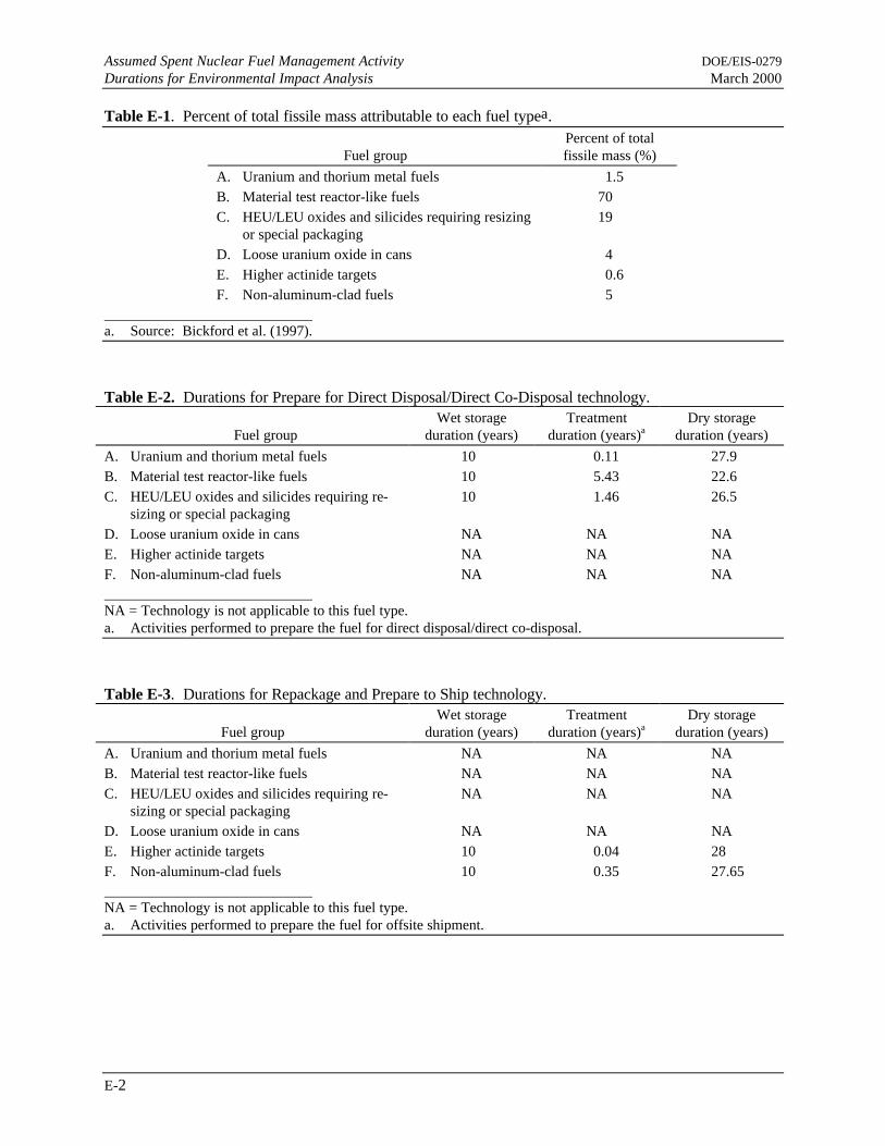
Assumed Spent Nuclear Fuel Management Activity DOE/EIS-0279Durations for Environmental Impact Analysis March 2000
E-2
Table E-1. Percent of total fissile mass attributable to each fuel typea.
Fuel groupPercent of totalfissile mass (%)
A. Uranium and thorium metal fuels 1.5B. Material test reactor-like fuels 70C. HEU/LEU oxides and silicides requiring resizing
or special packaging19
D. Loose uranium oxide in cans 4E. Higher actinide targets 0.6F. Non-aluminum-clad fuels 5
a. Source: Bickford et al. (1997).
Table E-2. Durations for Prepare for Direct Disposal/Direct Co-Disposal technology.
Fuel groupWet storage
duration (years)Treatment
duration (years)aDry storage
duration (years)
A. Uranium and thorium metal fuels 10 0.11 27.9B. Material test reactor-like fuels 10 5.43 22.6C. HEU/LEU oxides and silicides requiring re-
sizing or special packaging10 1.46 26.5
D. Loose uranium oxide in cans NA NA NAE. Higher actinide targets NA NA NAF. Non-aluminum-clad fuels NA NA NA NA = Technology is not applicable to this fuel type.a. Activities performed to prepare the fuel for direct disposal/direct co-disposal.
Table E-3. Durations for Repackage and Prepare to Ship technology.
Fuel groupWet storage
duration (years)Treatment
duration (years)aDry storage
duration (years)
A. Uranium and thorium metal fuels NA NA NAB. Material test reactor-like fuels NA NA NAC. HEU/LEU oxides and silicides requiring re-
sizing or special packagingNA NA NA
D. Loose uranium oxide in cans NA NA NAE. Higher actinide targets 10 0.04 28F. Non-aluminum-clad fuels 10 0.35 27.65 NA = Technology is not applicable to this fuel type.a. Activities performed to prepare the fuel for offsite shipment.
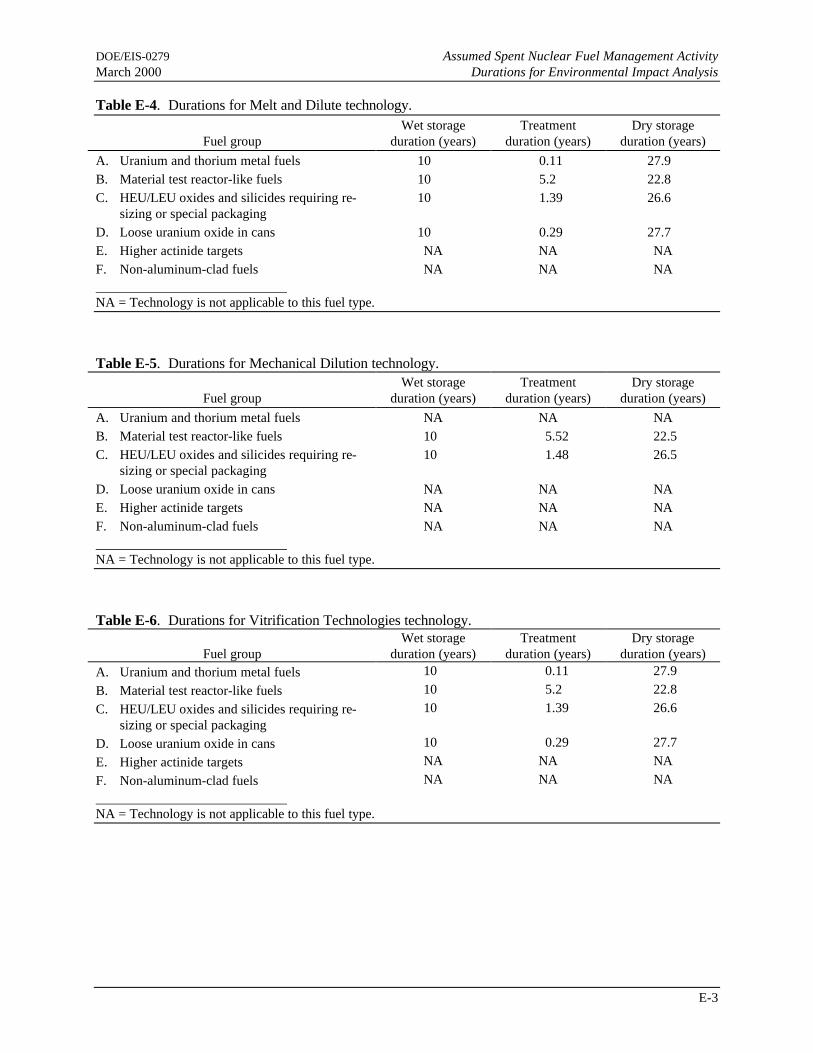
DOE/EIS-0279 Assumed Spent Nuclear Fuel Management ActivityMarch 2000 Durations for Environmental Impact Analysis
E-3
Table E-4. Durations for Melt and Dilute technology.
Fuel groupWet storage
duration (years)Treatment
duration (years)Dry storage
duration (years)
A. Uranium and thorium metal fuels 10 0.11 27.9B. Material test reactor-like fuels 10 5.2 22.8C. HEU/LEU oxides and silicides requiring re-
sizing or special packaging10 1.39 26.6
D. Loose uranium oxide in cans 10 0.29 27.7E. Higher actinide targets NA NA NAF. Non-aluminum-clad fuels NA NA NA NA = Technology is not applicable to this fuel type.
Table E-5. Durations for Mechanical Dilution technology.
Fuel groupWet storage
duration (years)Treatment
duration (years)Dry storage
duration (years)
A. Uranium and thorium metal fuels NA NA NAB. Material test reactor-like fuels 10 5.52 22.5C. HEU/LEU oxides and silicides requiring re-
sizing or special packaging10 1.48 26.5
D. Loose uranium oxide in cans NA NA NAE. Higher actinide targets NA NA NAF. Non-aluminum-clad fuels NA NA NA NA = Technology is not applicable to this fuel type.
Table E-6. Durations for Vitrification Technologies technology.
Fuel groupWet storage
duration (years)Treatment
duration (years)Dry storage
duration (years)A. Uranium and thorium metal fuels 10 0.11 27.9
B. Material test reactor-like fuels 10 5.2 22.8
C. HEU/LEU oxides and silicides requiring re-sizing or special packaging
10 1.39 26.6
D. Loose uranium oxide in cans 10 0.29 27.7
E. Higher actinide targets NA NA NA
F. Non-aluminum-clad fuels NA NA NA NA = Technology is not applicable to this fuel type.

Assumed Spent Nuclear Fuel Management Activity DOE/EIS-0279Durations for Environmental Impact Analysis March 2000
E-4
Table E-7. Durations for Electrometallurgical Treatment technology.
Fuel groupWet storage
duration (years)Treatment
duration (years)Dry storage
duration (years)A. Uranium and thorium metal fuels 10 0.11 27.9
B. Material test reactor-like fuels 10 5.2 22.8
C. HEU/LEU oxides and silicides requiring re-sizing or special packaging
10 1.39 26.6
D. Loose uranium oxide in cans 10 0.29 27.7
E. Higher actinide targets NA NA NA
F. Non-aluminum-clad fuels NA NA NA NA = Technology is not applicable to this fuel type.
Table E-8. Durations for Conventional Processing technology.
Fuel groupWet storage
duration (years)Treatment
duration (years)a,bDry storage
duration (years)c
A. Uranium and thorium metal fuels 9 0.2 1B. Material test reactor-like fuels 9 14.9 1C. HEU/LEU oxides and silicides requiring re-
sizing or special packaging9 7.5 1
D. Loose uranium oxide in cans 9 2.2 1E. Higher actinide targets NA NA NAF. Non-aluminum-clad fuels NA NA NA NA = Technology is not applicable to this fuel type.a. Durations represent active processing time and do not include downtimes normally associated with processing
activities.b. Duration assumes only a single dissolver is used. If two dissolvers were used, the duration would be decreased
by one-half.c. Indicates storage of resulting low enriched uranium awaiting sale.
Table E-9. Durations for Continued Wet Storage technology.
Fuel groupWet storage
duration (years)Treatment
duration (years)Dry storage
duration (years)
A. Uranium and thorium metal fuels 38 NA NAB. Material test reactor-like fuels 38 NA NAC. HEU/LEU oxides and silicides requiring re-
sizing or special packaging38 NA NA
D. Loose uranium oxide in cans 38 NA NAE. Higher actinide targets 38 NA NAF. Non-aluminum-clad fuels 38 NA NA NA = Not applicable.

DOE/EIS-0279 Assumed Spent Nuclear Fuel Management ActivityMarch 2000 Durations for Environmental Impact Analysis
E-5
References
Bickford, W. E., J. F. Krupa, D. L. McWhorter, M. E. Dupont, 1997, Savannah River Site Spent NuclearFuel Environmental Impact Statement Engineering Data Book for Routine Releases, WSRC-TR-97-0044, Westinghouse Savannah River Company, Aiken, South Carolina, April 8.
McWhorter, D. L., 1997, “SRS SNF Management EIS, SNF Processing Durations (U),” interofficememorandum to C. B. Shedrow, Westinghouse Savannah River Company, Aiken, South Carolina,May 28.

Assumed Spent Nuclear Fuel Management Activity DOE/EIS-0279Durations for Environmental Impact Analysis March 2000
E-6
canyon, 1Direct Disposal, 1, 2DOE, 1Electrometallurgical Treatment, 4energy consumption, 1HEU, 2, 3, 4
impacts, 1LEU, 2, 3, 4process, 1uranium, 2, 3, 4utilities, 1waste generation, 1

APPENDIX F
ESTIMATED INCREMENTAL NONRADIOLOGICALAIR CONCENTRATIONS ATTRIBUTABLE TO
SPENT NUCLEAR FUEL MANAGEMENT ACTIVITIES


DOE/EIS-0279 Estimated Incremental Nonradiological Air ConcentrationsMarch 2000 Attributable to Spent Nuclear Fuel Management Activities
F-iii
TABLE OF CONTENTS
List of Tables
Table Page
F-1 Estimated maximum incremental concentrations of nonradiological air pollutantsfor noninvolved worker - Uranium and Thorium Metal Fuels (Fuel Group A)(micrograms per cubic meter).......................................................................................... F-1
F-2 Estimated maximum incremental concentrations of nonradiological air pollutantsfor noninvolved worker - Materials Test Reactor-Like Fuels (Fuel Group B)(micrograms per cubic meter).......................................................................................... F-2
F-3 Estimated maximum incremental concentrations of nonradiological air pollutantsfor noninvolved worker - HEU/LEU Oxides and Silicides Requiring Resizing orSpecial Packaging (Fuel Group C) (micrograms per cubic meter)..................................... F-4
F-4 Estimated maximum incremental concentrations of nonradiological air pollutantsfor noninvolved worker - Loose Uranium Oxide in Cans (Fuel Group D)(micrograms per cubic meter).......................................................................................... F-5
F-5 Estimated maximum incremental concentrations of nonradiological air pollutantsfor noninvolved worker - Higher Actinide Targets (Fuel Group E)(micrograms per cubic meter).......................................................................................... F-6
F-6 Estimated maximum incremental concentrations of nonradiological air pollutantsat SRS boundary for Uranium and Thorium Metal Fuels (Fuel Group A)(micrograms per cubic meter).......................................................................................... F-7
F-7 Estimated maximum incremental concentrations of nonradiological air pollutantsat SRS boundary for Materials Test Reactor-Like Fuels (Fuel Group B)micrograms per cubic meter) ........................................................................................... F-9
F-8 Estimated maximum incremental concentrations of nonradiological air pollutantsat SRS boundary for HEU/LEU Oxides and Silicides Requiring Resizing orSpecial Packaging (Fuel Group C) (micrograms per cubic meter)..................................... F-11
F-9 Estimated maximum incremental concentrations of nonradiological air pollutantsat SRS boundary for Loose Uranium Oxide in Cans (Fuel Group D)(micrograms per cubic meter).......................................................................................... F-12
F-10 Estimated maximum incremental concentrations of nonradiological air pollutantsat SRS boundary for Higher Actinide Targets (Fuel Group E)(micrograms per cubic meter).......................................................................................... F-14


DOE/EIS-0279 Estimated Incremental Nonradiological Air ConcentrationsMarch 2000 Attributable to Spent Nuclear Fuel Management Activities
F-1
Table F-1. Estimated maximum incremental concentrations of nonradiological air pollutants fornoninvolved worker - Uranium and Thorium Metal Fuels (Fuel Group A).a
Averaging Regulatory Incremental concentration for technology optionc
Pollutant time standardb 1 2 3 4 5 6 7 8Toxic pollutants (mg/m3)Nitric acid 24-hour 5 <0.01 NA <0.01 NA 2.61 <0.01 2.61 <0.011,1,1-trichloroethane 24-hour 1,900 – NA – NA 0.02 – 0.02 –Benzene 24-hour 3.19 – NA – NA 0.02 – 0.02 –Ethanolamine 24-hour 6 <0.01 NA <0.01 NA <0.01 <0.01 <0.01 <0.01Ethyl benzene 24-hour 435 – NA – NA <0.01 – <0.01 –Ethylene glycol 24-hour None <0.01 NA <0.01 NA <0.01 <0.01 <0.01 <0.01Formaldehyde 24-hour 0.75 <0.01 NA <0.01 NA <0.01 <0.01 <0.01 <0.01Glycol ethers 24-hour 80 <0.01 NA <0.01 NA <0.01 <0.01 <0.01 <0.01Hexachloronaphthalene 24-hour 0.2 <0.01 NA <0.01 NA <0.01 <0.01 <0.01 <0.01Hexane 24-hour 1,800 <0.01 NA <0.01 NA 0.02 <0.01 0.02 <0.01Manganese 24-hour 5 – NA – NA <0.01 – <0.01 –Mercury 24-hour 0.1 – NA – NA – – <0.01 –Methyl alcohol 24-hour 260 <0.01 NA <0.01 NA <0.01 <0.01 <0.01 <0.01Methyl ethyl ketone 24-hour 590 <0.01 NA <0.01 NA <0.01 <0.01 <0.01 <0.01Methyl isobutyl ketone 24-hour 410 – NA – NA <0.01 – <0.01 –Methylene chloride 24-hour 86.7 – NA – NA 0.02 – 0.02 –Napthalene 24-hour 50 <0.01 NA <0.01 NA <0.01 <0.01 <0.01 <0.01Phenol 24-hour 19 – NA – NA <0.01 – <0.01 –Phosphorus 24-hour 0.1 – NA – NA <0.01 – <0.01 –Sodium hydroxide 24-hour 2.0 – NA – NA <0.01 – <0.01 –Toluene 24-hour 754 <0.01 NA <0.01 NA 0.02 <0.01 0.02 <0.01Trichloroethene 24-hour 537 – NA – NA <0.01 – <0.01 –Vinyl acetate 24-hour None – NA – NA <0.01 – <0.01 –Xylene 24-hour 435 <0.01 NA <0.01 NA 0.03 <0.01 0.03 <0.01
Criteria pollutants (µg/m3)Nitrogen oxides Annual NA 0.02 NA 0.02 NA 36.34 0.02 36.34 –Total suspendedparticulates (total dust)
24-hour 15 <0.01 NA <0.01 NA 0.33 <0.01 0.33 –
Particulate matter(respirable fraction)
Annual 5 0.03 NA 0.03 NA 0.02 0.03 0.02 –
24-hour NA 0.33 NA 0.33 NA 0.20 0.33 0.20 –Carbon monoxide 8-hour 55 0.08 NA 0.12 NA 1.57 0.12 1.57 <0.01
1-hour NA 0.26 NA 0.39 NA 4.89 0.39 4.89 <0.01Sulfur dioxide Annual NA <0.01 NA <0.01 NA 0.02 <0.01 0.02 –
8-hour 13 <0.01 NA <0.01 NA 0.28 <0.01 0.28 –3-hour NA <0.01 NA <0.01 NA 0.68 <0.01 0.68 –
Gaseous fluorides 1-month None – NA – NA 0.10 – 0.10 –1-week NA – NA – NA 0.17 – 0.17 –24-hour NA – NA – NA 0.52 – 0.52 –12-hour NA – NA – NA 0.76 – 0.76 –
Ozone (as VOC) 1-hour 0.2 NC NA NC NA NC NC NC –
NA = Technology is not applicable to this fuel type.– = No air emission associated with this option.NC = Not Calculated.VOC = volatile organic compound.a. Not all constituents listed in this table appear in Tables 3.3-3 or 3.3-4 because many constituents are not expected to
impact SRS ambient air concentrations.b. NIOSH (1991) and OSHA TWAs.c. Technology options: 1 = Prepare for Direct Disposal/Direct Co-Disposal; 2 = Repackage and Prepare to Ship; 3 = Melt
and Dilute; 4 = Mechanical Dilution; 5 = Vitrification Technologies; 6 = Electrometallurgical Treatment; 7 = ConventionalProcessing; and 8 = Continued Wet Storage.

Estimated Incremental Nonradiological Air Concentrations DOE/EIS-0279Attributable to Spent Nuclear Fuel Management Activities March 2000
F-2
Table F-2. Estimated maximum incremental concentrations of nonradiological air pollutants fornoninvolved worker - Materials Test Reactor-Like Fuels (Fuel Group B).a
Averaging Regulatory Incremental concentration for technology optionc
Pollutant time standardb 1 2 3 4 5 6 7 8Toxic pollutants (mg/m3)Nitric acid 24-hour 5 <0.01 NA <0.01 <0.01 3.91 <0.01 3.91 <0.011,1,1-trichloroethane 24-hour 1,900 – NA – – 0.02 – 0.02 –Benzene 24-hour 3.19 – NA – – 0.03 – 0.03 –Ethanolamine 24-hour 6 <0.01 NA <0.01 <0.01 <0.01 <0.01 <0.01 <0.01Ethyl benzene 24-hour 435 – NA – – <0.01 – <0.01 –Ethylene glycol 24-hour None <0.01 NA <0.01 <0.01 <0.01 <0.01 <0.01 <0.01Formaldehyde 24-hour 0.75 <0.01 NA <0.01 <0.01 <0.01 <0.01 <0.01 <0.01Glycol ethers 24-hour 80 <0.01 NA <0.01 <0.01 <0.01 <0.01 <0.01 <0.01Hexachloronaphthalene 24-hour 0.2 <0.01 NA <0.01 <0.01 <0.01 <0.01 <0.01 <0.01Hexane 24-hour 1,800 <0.01 NA <0.01 <0.01 0.03 <0.01 0.03 <0.01Manganese 24-hour 5 – NA – – <0.01 – <0.01 –Mercury 24-hour 0.1 – NA – – – – <0.01 –Methyl alcohol 24-hour 260 <0.01 NA <0.01 <0.01 <0.01 <0.01 <0.01 <0.01Methyl ethyl ketone 24-hour 590 <0.01 NA <0.01 <0.01 <0.01 <0.01 <0.01 <0.01Methyl isobutyl ketone 24-hour 410 – NA – – <0.01 – <0.01 –Methylene chloride 24-hour 86.7 – NA – – 0.03 – 0.03 –Napthalene 24-hour 50 <0.01 NA <0.01 <0.01 <0.01 <0.01 <0.01 <0.01Phenol 24-hour 19 – NA – – <0.01 – <0.01 –Phosphorus 24-hour 0.1 – NA – – <0.01 – <0.01 –Sodium hydroxide 24-hour 2.0 – NA – – <0.01 – <0.01 –Toluene 24-hour 754 <0.01 NA <0.01 <0.01 0.03 <0.01 0.03 <0.01Trichloroethene 24-hour 537 – NA – – <0.01 – <0.01 –Vinyl acetate 24-hour None – NA – – <0.01 – <0.01 –Xylene 24-hour 435 <0.01 NA <0.01 <0.01 0.05 <0.01 0.05 <0.01
Criteria pollutants (µg/m3)Nitrogen oxides Annual NA 0.02 NA 0.04 0.02 54.51 0.04 54.51 –Total suspendedparticulates (total dust)
24-hour 15 <0.01 NA <0.01 <0.01 0.49 <0.01 0.49 –
Particulate matter(respirable fraction)
Annual 5 0.04 NA 0.04 0.04 0.03 0.04 0.03 –
24-hour NA 0.49 NA 0.49 0.49 0.30 0.49 0.30 –Carbon monoxide 8-hour 55 0.12 NA 0.19 0.12 2.35 0.19 2.35 <0.01
1-hour NA 0.39 NA 0.58 0.39 7.34 0.58 7.34 <0.01Sulfur dioxide Annual NA <0.01 NA <0.01 <0.01 0.04 <0.01 0.04 –
8-hour 13 <0.01 NA <0.01 <0.01 0.42 <0.01 0.42 –3-hour NA <0.01 NA <0.01 <0.01 1.02 <0.01 1.02 –
Gaseous fluorides 1-month None – NA – – 0.14 – 0.14 –1-week NA – NA – – 0.26 – 0.26 –24-hour NA – NA – – 0.78 – 0.78 –12-hour NA – NA – – 1.14 – 1.14 –
Ozone (as VOC) 1-hour 0.2 NC NA NC NC NC NC NC – NA = Technology is not applicable to this fuel type.– = No air emission associated with this option.NC = Not Calculated.VOC = volatile organic compound.a. Not all constituents listed in this table appear in Tables 3.3-3 or 3.3-4 because many constituents are not expected to
impact SRS ambient air concentrations.b. NIOSH (1991) and OSHA TWAs.c. Technology options: 1 = Prepare for Direct Disposal/Direct Co-Disposal; 2 = Repackage and Prepare to Ship; 3 = Melt
and Dilute; 4 = Mechanical Dilution; 5 = Vitrification Technologies; 6 = Electrometallurgical Treatment; 7 = ConventionalProcessing; and 8 = Continued Wet Storage.

DOE/EIS-0279 Estimated Incremental Nonradiological Air ConcentrationsMarch 2000 Attributable to Spent Nuclear Fuel Management Activities
F-3

Estimated Incremental Nonradiological Air Concentrations DOE/EIS-0279Attributable to Spent Nuclear Fuel Management Activities March 2000
F-4
Table F-3. Estimated maximum incremental concentrations of nonradiological air pollutants fornoninvolved worker - HEU/LEU Oxides and Silicides Requiring Resizing or Special Packaging (FuelGroup C).a
Averaging Regulatory Incremental concentration for technology optionc
Pollutant time standardb 1 2 3 4 5 6 7 8Toxic pollutants (mg/m3)Nitric acid 24-hour 5 <0.01 NA <0.01 <0.01 1.30 <0.01 1.30 <0.011,1,1-trichloroethane 24-hour 1,900 – NA – – <0.01 – <0.01 –Benzene 24-hour 3.19 – NA – – <0.01 – <0.01 –Ethanolamine 24-hour 6 <0.01 NA <0.01 <0.01 <0.01 <0.01 <0.01 <0.01Ethyl benzene 24-hour 435 – NA – – <0.01 – <0.01 –Ethylene glycol 24-hour None <0.01 NA <0.01 <0.01 <0.01 <0.01 <0.01 <0.01Formaldehyde 24-hour 0.75 <0.01 NA <0.01 <0.01 <0.01 <0.01 <0.01 <0.01Glycol ethers 24-hour 80 <0.01 NA <0.01 <0.01 <0.01 <0.01 <0.01 <0.01Hexachloronaphthalene 24-hour 0.2 <0.01 NA <0.01 <0.01 <0.01 <0.01 <0.01 <0.01Hexane 24-hour 1,800 <0.01 NA <0.01 <0.01 <0.01 <0.01 <0.01 <0.01Manganese 24-hour 5 – NA – – <0.01 – <0.01 –Mercury 24-hour 0.1 – NA – – – – <0.01 –Methyl alcohol 24-hour 260 <0.01 NA <0.01 <0.01 <0.01 <0.01 <0.01 <0.01Methyl ethyl ketone 24-hour 590 <0.01 NA <0.01 <0.01 <0.01 <0.01 <0.01 <0.01Methyl isobutyl ketone 24-hour 410 – NA – – <0.01 – <0.01 –Methylene chloride 24-hour 86.7 – NA – – <0.01 – <0.01 –Napthalene 24-hour 50 <0.01 NA <0.01 <0.01 <0.01 <0.01 <0.01 <0.01Phenol 24-hour 19 – NA – – <0.01 – <0.01 –Phosphorus 24-hour 0.1 – NA – – <0.01 – <0.01 –Sodium hydroxide 24-hour 2.0 – NA – – <0.01 – <0.01 –Toluene 24-hour 754 <0.01 NA <0.01 <0.01 <0.01 <0.01 <0.01 <0.01Trichloroethene 24-hour 537 - NA - - <0.01 – <0.01 –Vinyl acetate 24-hour None - NA - - <0.01 – <0.01 –Xylene 24-hour 435 <0.01 NA <0.01 <0.01 0.02 <0.01 0.02 <0.01
Criteria pollutants (µg/m3)Nitrogen oxides Annual NA <0.01 NA 0.01 <0.01 18.17 0.01 18.17 –Total suspendedparticulates (total dust)
24-hour 15 <0.01 NA <0.01 <0.01 0.16 <0.01 0.16 –
Particulate matter(respirable fraction)
Annual 5 0.01 NA 0.01 0.01 <0.01 0.01 <0.01 –
24-hour NA 0.16 NA 0.16 0.16 0.10 0.16 0.10 –Carbon monoxide 8-hour 55 0.04 NA 0.06 0.04 0.78 0.06 0.78 <0.01
1-hour NA 0.13 NA 0.19 0.13 2.45 0.19 2.45 <0.01Sulfur dioxide Annual NA <0.01 NA <0.01 <0.01 0.01 <0.01 0.01 –
8-hour 13 <0.01 NA <0.01 <0.01 0.14 <0.01 0.14 –3-hour NA <0.01 NA <0.01 <0.01 0.34 <0.01 0.34 –
Gaseous fluorides 1-month None – NA – – 0.05 – 0.05 –1-week NA – NA – – 0.09 – 0.09 –24-hour NA – NA – – 0.26 – 0.26 –12-hour NA – NA – – 0.38 – 0.38 –
Ozone (as VOC) 1-hour 0.2 NC NA NC NC NC NC NC –
NA = Technology is not applicable to this fuel type. LEU = low enriched uranium.– = No air emission associated with this option. NC = Not Calculated.HEU = highly enriched uranium. VOC = volatile organic compound.a. Not all constituents listed in this table appear in Tables 3.3-3 or 3.3-4 because many constituents are not expected to
impact SRS ambient air concentrations.b. NIOSH (1991) and OSHA TWAs.c. Technology options: 1 = Prepare for Direct Disposal/Direct Co-Disposal; 2 = Repackage and Prepare to Ship; 3 = Melt
and Dilute; 4 = Mechanical Dilution; 5 = Vitrification Technologies; 6 = Electrometallurgical Treatment; 7 = ConventionalProcessing; and 8 = Continued Wet Storage.

DOE/EIS-0279 Estimated Incremental Nonradiological Air ConcentrationsMarch 2000 Attributable to Spent Nuclear Fuel Management Activities
F-5
Table F-4. Estimated maximum incremental concentrations of nonradiological air pollutants fornoninvolved worker - Loose Uranium Oxide in Cans (Fuel Group D).a
Averaging Regulatory Incremental concentration for technology optionc
Pollutant time standardb 1 2 3 4 5 6 7 8Toxic pollutants (mg/m3)Nitric acid 24-hour 5 NA NA <0.01 NA 0.13 <0.01 0.13 <0.011,1,1-trichloroethane 24-hour 1,900 NA NA – NA <0.01 – <0.01 –Benzene 24-hour 3.19 NA NA – NA <0.01 – <0.01 –Ethanolamine 24-hour 6 NA NA <0.01 NA <0.01 <0.01 <0.01 <0.01Ethyl benzene 24-hour 435 NA NA – NA <0.01 – <0.01 –Ethylene glycol 24-hour None NA NA <0.01 NA <0.01 <0.01 <0.01 <0.01Formaldehyde 24-hour 0.75 NA NA <0.01 NA <0.01 <0.01 <0.01 <0.01Glycol ethers 24-hour 80 NA NA <0.01 NA <0.01 <0.01 <0.01 <0.01Hexachloronaphthalene 24-hour 0.2 NA NA <0.01 NA <0.01 <0.01 <0.01 <0.01Hexane 24-hour 1,800 NA NA <0.01 NA <0.01 <0.01 <0.01 <0.01Manganese 24-hour 5 NA NA – NA <0.01 – <0.01 –Mercury 24-hour 0.1 NA NA – NA – – <0.01 –Methyl alcohol 24-hour 260 NA NA <0.01 NA <0.01 <0.01 <0.01 <0.01Methyl ethyl ketone 24-hour 590 NA NA <0.01 NA <0.01 <0.01 <0.01 <0.01Methyl isobutyl ketone 24-hour 410 NA NA – NA <0.01 – <0.01 –Methylene chloride 24-hour 86.7 NA NA – NA <0.01 – <0.01 –Napthalene 24-hour 50 NA NA <0.01 NA <0.01 <0.01 <0.01 <0.01Phenol 24-hour 19 NA NA – NA <0.01 – <0.01 –Phosphorus 24-hour 0.1 NA NA – NA <0.01 – <0.01 –Sodium hydroxide 24-hour 2.0 NA NA – NA <0.01 – <0.01 –Toluene 24-hour 754 NA NA <0.01 NA <0.01 <0.01 <0.01 <0.01Trichloroethene 24-hour 537 NA NA – NA <0.01 – <0.01 –Vinyl acetate 24-hour None NA NA – NA <0.01 – <0.01 –Xylene 24-hour 435 NA NA <0.01 NA <0.01 <0.01 <0.01 <0.01
Criteria pollutants (µg/m3)Nitrogen oxides Annual NA NA NA <0.01 NA 1.82 <0.01 1.82 –Total suspendedparticulates (total dust)
24-hour 15 NA NA <0.01 NA 0.02 <0.01 0.02 –
Particulate matter(respirable fraction)
Annual 5 NA NA <0.01 NA <0.01 <0.01 <0.01 –
24-hour NA NA NA 0.02 NA 0.01 0.02 0.01 –Carbon monoxide 8-hour 55 NA NA <0.01 NA 0.08 <0.01 0.08 <0.01
1-hour NA NA NA 0.02 NA 0.24 0.02 0.24 <0.01Sulfur dioxide Annual NA NA NA <0.01 NA <0.01 <0.01 <0.01 –
8-hour 13 NA NA <0.01 NA 0.01 <0.01 0.01 –3-hour NA NA NA <0.01 NA 0.03 <0.01 0.03 –
Gaseous fluorides 1-month None NA NA – NA <0.01 – <0.01 –1-week NA NA NA – NA <0.01 – <0.01 –24-hour NA NA NA – NA 0.03 – 0.03 –12-hour NA NA NA – NA 0.04 – 0.04 –
Ozone (as VOC) 1-hour 0.2 NA NA NC NA NC NC NC –
NA = Technology is not applicable to this fuel type.– = No air emission associated with this option.NC = Not Calculated.VOC = volatile organic compound.a. Not all constituents listed in this table appear in Tables 3.3-3 or 3.3-4 because many constituents are not expected to
impact SRS ambient air concentrations.b. NIOSH (1991) and OSHA TWAs.c. Technology options: 1 = Prepare for Direct Disposal/Direct Co-Disposal; 2 = Repackage and Prepare to Ship; 3 = Melt
and Dilute; 4 = Mechanical Dilution; 5 = Vitrification Technologies; 6 = Electrometallurgical Treatment; 7 = ConventionalProcessing; and 8 = Continued Wet Storage.

Estimated Incremental Nonradiological Air Concentrations DOE/EIS-0279Attributable to Spent Nuclear Fuel Management Activities March 2000
F-6
Table F-5. Estimated maximum incremental concentrations of nonradiological air pollutants fornoninvolved worker - Higher Actinide Targets (Fuel Group E).a
Averaging Regulatory Incremental concentration for technology optionc
Pollutant time standardb 1 2 3 4 5 6 7 8Toxic pollutants (mg/m3)Nitric acid 24-hour 5 NA – NA NA NA NA NA <0.011,1,1-Trichloroethane 24-hour 1,900 NA – NA NA NA NA NA –Benzene 24-hour 3.19 NA – NA NA NA NA NA –Ethanolamine 24-hour 6 NA – NA NA NA NA NA <0.01Ethyl benzene 24-hour 435 NA – NA NA NA NA NA –Ethylene glycol 24-hour None NA – NA NA NA NA NA <0.01Formaldehyde 24-hour 0.75 NA – NA NA NA NA NA <0.01Glycol ethers 24-hour 80 NA – NA NA NA NA NA <0.01Hexachloronaphthalene 24-hour 0.2 NA – NA NA NA NA NA <0.01Hexane 24-hour 1,800 NA – NA NA NA NA NA <0.01Manganese 24-hour 5 NA – NA NA NA NA NA –Mercury 24-hour 0.1 NA – NA NA NA NA NA –Methyl alcohol 24-hour 260 NA – NA NA NA NA NA <0.01Methyl ethyl ketone 24-hour 590 NA – NA NA NA NA NA <0.01Methyl isobutyl ketone 24-hour 410 NA – NA NA NA NA NA –Methylene chloride 24-hour 86.7 NA – NA NA NA NA NA –Napthalene 24-hour 50 NA – NA NA NA NA NA <0.01Phenol 24-hour 19 NA – NA NA NA NA NA –Phosphorus 24-hour 0.1 NA – NA NA NA NA NA –Sodium hydroxide 24-hour 2.0 NA – NA NA NA NA NA –Toluene 24-hour 754 NA – NA NA NA NA NA <0.01Trichloroethene 24-hour 537 NA – NA NA NA NA NA –Vinyl acetate 24-hour None NA – NA NA NA NA NA –Xylene 24-hour 435 NA – NA NA NA NA NA <0.01
Criteria pollutants (µg/m3)Nitrogen oxides Annual NA NA – NA NA NA NA NA –Total suspendedparticulates (total dust)
24-hour 15 NA – NA NA NA NA NA –
Particulate matter(respirable fraction)
Annual 5 NA – NA NA NA NA NA –
24-hour NA NA – NA NA NA NA NA –Carbon monoxide 8-hour 55 NA – NA NA NA NA NA <0.01
1-hour NA NA – NA NA NA NA NA <0.01Sulfur dioxide Annual NA NA – NA NA NA NA NA –
8-hour 13 NA – NA NA NA NA NA –3-hour NA NA – NA NA NA NA NA –
Gaseous fluorides 1-month None NA – NA NA NA NA NA –1-week NA NA – NA NA NA NA NA –24-hour NA NA – NA NA NA NA NA –12-hour NA NA – NA NA NA NA NA –
Ozone (as VOC) 1-hour 0.2 NA – NA NA NA NA NA –
NA = Technology is not applicable to this fuel type.– = No air emission associated with this option.NC = Not Calculated.VOC = volatile organic compound.a. Not all constituents listed in this table appear in Tables 3.3-3 or 3.3-4 because many constituents are not expected to
impact SRS ambient air concentrations.b. NIOSH (1991) and OSHA TWAs.c. Technology options: 1 = Prepare for Direct Disposal/Direct Co-Disposal; 2 = Repackage and Prepare to Ship; 3 = Melt
and Dilute; 4 = Mechanical Dilution; 5 = Vitrification Technologies; 6 = Electrometallurgical Treatment; 7 = ConventionalProcessing; and 8 = Continued Wet Storage.

DOE/EIS-0279 Estimated Incremental Nonradiological Air ConcentrationsMarch 2000 Attributable to Spent Nuclear Fuel Management Activities
F-7
Table F-6. Estimated maximum incremental concentrations of nonradiological air pollutants at SRSboundary for Uranium and Thorium Metal Fuels (Fuel Group A).a
Averaging Regulatory Incremental concentration for technology optionb
Pollutant time standard 1 2 3 4 5 6 7 8Toxic pollutants (mg/m3)Nitric acid 24-hour 125 – NA – NA 0.10 – 0.10 –1,1,1-trichloroethane 24-hour 9,550 <0.01 NA <0.01 NA <0.01 <0.01 <0.01 <0.01Benzene 24-hour 150 – NA – NA <0.01 – <0.01 –Ethanolamine 24-hour 200 <0.01 NA <0.01 NA <0.01 <0.01 <0.01 <0.01Ethyl benzene 24-hour 4,350 – NA – NA <0.01 – <0.01 –Ethylene glycol 24-hour 650 <0.01 NA <0.01 NA <0.01 <0.01 <0.01 <0.01Formaldehyde 24-hour 15 <0.01 NA <0.01 NA <0.01 <0.01 <0.01 <0.01Glycol ethers 24-hour + <0.01 NA <0.01 NA <0.01 <0.01 <0.01 <0.01Hexachloronaphthalene 24-hour 1 <0.01 NA <0.01 NA <0.01 <0.01 <0.01 <0.01Hexane 24-hour 900 <0.01 NA <0.01 NA <0.01 <0.01 <0.01 <0.01Manganese 24-hour 25 – NA – NA <0.01 – <0.01 –Mercury 24-hour 0.25 – NA – NA – – <0.01 –Methyl alcohol 24-hour 1,310 <0.01 NA <0.01 NA <0.01 <0.01 <0.01 <0.01Methyl ethyl ketone 24-hour 14,750 <0.01 NA <0.01 NA <0.01 <0.01 <0.01 <0.01Methyl isobutyl ketone 24-hour 2,050 – NA – NA <0.01 – <0.01 –Methylene chloride 24-hour 8,750 – NA – NA <0.01 – <0.01 –Napthalene 24-hour 1,250 <0.01 NA <0.01 NA <0.01 <0.01 <0.01 <0.01Phenol 24-hour 190 – NA – NA <0.01 – <0.01 –Phosphorus 24-hour 0.5 – NA – NA <0.01 – <0.01 –Sodium hydroxide 24-hour 50 – NA – NA <0.01 – <0.01 –Toluene 24-hour 2,000 <0.01 NA <0.01 NA <0.01 <0.01 <0.01 <0.01Trichloroethene 24-hour 6,750 – NA – NA <0.01 – <0.01 –Vinyl acetate 24-hour 176 – NA – NA <0.01 – <0.01 –Xylene 24-hour 4,350 <0.01 NA <0.01 NA <0.01 <0.01 <0.01 <0.01
Criteria pollutants (µg/m3)Nitrogen oxides Annual 100 <0.01 NA <0.01 NA 1.10 <0.01 1.10 <0.01Total suspendedparticulates (total dust)
Annual 75 <0.01 NA <0.01 NA <0.01 <0.01 <0.01 <0.01
Particulate matter(respirable fraction)
Annual 50 – NA – NA <0.01 – <0.01 –
24-hour 150 – NA – NA 0.04 – 0.04 –Carbon monoxide 8-hour 10,000 0.02 NA 0.03 NA 0.43 0.03 0.43 <0.01
1-hour 40,000 0.12 NA 0.18 NA 3.20 0.18 3.20 <0.01Sulfur dioxide Annual 80 <0.01 NA <0.01 NA <0.01 <0.01 <0.01 –
8-hour 365 <0.01 NA 0.01 NA 0.04 0.01 0.04 –3-hour 1,300 – NA – NA 0.32 – 0.32 –
Gaseous fluorides 1-month 0.8 – NA – NA <0.01 – <0.01 –1-week 1.6 – NA – NA 0.01 – 0.01 –24-hour 2.9 – NA – NA 0.02 – 0.02 –12-hour 3.7 – NA – NA 0.04 – 0.04 –
Ozone (as VOC) 1-hour 235 0.05 NA 0.07 NA 0.26 0.08 0.26 –
NA = Technology is not applicable to this fuel type.- = No air emission associated with this option.+ = No state standard.VOC = volatile organic compound.a. Not all constituents listed in this table appear in Tables 3.3-3 or 3.3-4 because many constituents are not expected to
impact SRS ambient air concentrations.

Estimated Incremental Nonradiological Air Concentrations DOE/EIS-0279Attributable to Spent Nuclear Fuel Management Activities March 2000
F-8
b. Technology options: 1 = Prepare for Direct Disposal/Direct Co-Disposal; 2 = Repackage and Prepare to Ship; 3 = Meltand Dilute; 4 = Mechanical Dilution; 5 = Vitrification Technologies; 6 = Electrometallurgical Treatment; 7 = ConventionalProcessing; and 8 = Continued Wet Storage.

DOE/EIS-0279 Estimated Incremental Nonradiological Air ConcentrationsMarch 2000 Attributable to Spent Nuclear Fuel Management Activities
F-9
Table F-7. Estimated maximum incremental concentrations of nonradiological air pollutants at SRSboundary for Materials Test Reactor-Like Fuels (Fuel Group B).a
Averaging Regulatory Incremental concentration for technology optionb
Pollutant time standard 1 2 3 4 5 6 7 8Toxic pollutants (mg/m3)Nitric acid 24-hour 125 – NA – – 0.15 – 0.15 –1,1,1-trichloroethane 24-hour 9,550 <0.01 NA <0.01 <0.01 <0.01 <0.01 <0.01 <0.01Benzene 24-hour 150 – NA – – <0.01 – <0.01 –Ethanolamine 24-hour 200 <0.01 NA <0.01 <0.01 <0.01 <0.01 <0.01 <0.01Ethyl benzene 24-hour 4,350 – NA – – <0.01 – <0.01 –Ethylene glycol 24-hour 650 <0.01 NA <0.01 <0.01 <0.01 <0.01 <0.01 <0.01Formaldehyde 24-hour 15 <0.01 NA <0.01 <0.01 <0.01 <0.01 <0.01 <0.01Glycol ethers 24-hour + <0.01 NA <0.01 <0.01 <0.01 <0.01 <0.01 <0.01Hexachloronaphthalene 24-hour 1 <0.01 NA <0.01 <0.01 <0.01 <0.01 <0.01 <0.01Hexane 24-hour 900 <0.01 NA <0.01 <0.01 <0.01 <0.01 <0.01 <0.01Manganese 24-hour 25 – NA – – <0.01 – <0.01 –Mercury 24-hour 0.25 – NA – – – – <0.01 –Methyl alcohol 24-hour 1310 <0.01 NA <0.01 <0.01 <0.01 <0.01 <0.01 <0.01Methyl ethyl ketone 24-hour 14,750 <0.01 NA <0.01 <0.01 <0.01 <0.01 <0.01 <0.01Methyl isobutyl ketone 24-hour 2,050 – NA – – <0.01 – <0.01 –Methylene chloride 24-hour 8,750 – NA – – <0.01 – <0.01 –Napthalene 24-hour 1,250 <0.01 NA <0.01 <0.01 <0.01 <0.01 <0.01 <0.01Phenol 24-hour 190 – NA – – <0.01 – <0.01 –Phosphorus 24-hour 0.5 – NA – – <0.01 – <0.01 –Sodium hydroxide 24-hour 50 – NA – – <0.01 – <0.01 –Toluene 24-hour 2,000 <0.01 NA <0.01 <0.01 <0.01 <0.01 <0.01 <0.01Trichloroethene 24-hour 6,750 – NA – – <0.01 – <0.01 –Vinyl acetate 24-hour 176 – NA – – <0.01 – <0.01 –Xylene 24-hour 4,350 <0.01 NA <0.01 <0.01 <0.01 <0.01 <0.01 <0.01
Criteria pollutants (µg/m3)Nitrogen oxide Annual 100 <0.01 NA <0.01 <0.01 1.65 <0.01 1.65 <0.01Total suspendedparticulates (total dust)
Annual 75 <0.01 NA <0.01 <0.01 <0.01 <0.01 <0.01 <0.01
Particulate matter(respirable fraction)
Annual 50 – NA – – <0.01 – <0.01 –
24-hour 150 – NA – – 0.06 – 0.06 –Carbon monoxide 8-hour 10,000 0.03 NA 0.05 0.03 0.65 0.05 0.65 <0.01
1-hour 40,000 0.18 NA 0.27 0.18 4.80 0.27 4.80 <0.01Sulfur dioxide Annual 80 <0.01 NA <0.01 <0.01 <0.01 <0.01 <0.01 –
8-hour 365 0.01 NA 0.02 0.01 0.06 0.02 0.06 –3-hour 1,300 – NA – – 0.48 – 0.48 –
Gaseous fluorides 1-month 0.8 – NA – – <0.01 – <0.01 –1-week 1.6 – NA – – 0.02 – 0.02 –24-hour 2.9 – NA – – 0.03 – 0.03 –12-hour 3.7 – NA – – 0.06 – 0.06 –
Ozone (as VOC) 1-hour 235 0.08 NA 0.11 0.08 0.39 0.11 0.39 –
NA = Technology is not applicable to this fuel type.– = No air emission associated with this option.+ = No state standard.VOC = volatile organic compound.a. Not all constituents listed in this table appear in Tables 3.3-3 or 3.3-4 because many constituents are not expected to
impact SRS ambient air concentrations.

Estimated Incremental Nonradiological Air Concentrations DOE/EIS-0279Attributable to Spent Nuclear Fuel Management Activities March 2000
F-10
b. Technology options: 1 = Prepare for Direct Disposal/Direct Co-Disposal; 2 = Repackage and Prepare to Ship; 3 = Meltand Dilute; 4 = Mechanical Dilution; 5 = Vitrification Technologies; 6 = Electrometallurgical Treatment; 7 = ConventionalProcessing; and 8 = Continued Wet Storage.

DOE/EIS-0279 Estimated Incremental Nonradiological Air ConcentrationsMarch 2000 Attributable to Spent Nuclear Fuel Management Activities
F-11
Table F-8. Estimated maximum incremental concentrations of nonradiological air pollutants at SRSboundary for HEU/LEU Oxides and Silicides Requiring Resizing or Special Packaging (Fuel Group C).a
Averaging Regulatory Incremental concentration for technology optionb
Pollutant time standard 1 2 3 4 5 6 7 8Toxic pollutants (mg/m3)Nitric acid 24-hour 125 – NA – – 0.05 – 0.05 –1,1,1-trichloroethane 24-hour 9,550 <0.01 NA <0.01 <0.01 <0.01 <0.01 <0.01 <0.01Benzene 24-hour 150 – NA – – <0.01 – <0.01 –Ethanolamine 24-hour 200 <0.01 NA <0.01 <0.01 <0.01 <0.01 <0.01 <0.01Ethyl benzene 24-hour 4,350 – NA – – <0.01 – <0.01 –Ethylene glycol 24-hour 650 <0.01 NA <0.01 <0.01 <0.01 <0.01 <0.01 <0.01Formaldehyde 24-hour 15 <0.01 NA <0.01 <0.01 <0.01 <0.01 <0.01 <0.01Glycol ethers 24-hour + <0.01 NA <0.01 <0.01 <0.01 <0.01 <0.01 <0.01Hexachloronaphthalene 24-hour 1 <0.01 NA <0.01 <0.01 <0.01 <0.01 <0.01 <0.01Hexane 24-hour 900 <0.01 NA <0.01 <0.01 <0.01 <0.01 <0.01 <0.01Manganese 24-hour 25 – NA – – <0.01 – <0.01 –Mercury 24-hour 0.25 – NA – – – – <0.01 –Methyl alcohol 24-hour 1310 <0.01 NA <0.01 <0.01 <0.01 <0.01 <0.01 <0.01Methyl ethyl ketone 24-hour 14,750 <0.01 NA <0.01 <0.01 <0.01 <0.01 <0.01 <0.01Methyl isobutyl ketone 24-hour 2,050 – NA – – <0.01 – <0.01 –Methylene chloride 24-hour 8,750 – NA – – <0.01 – <0.01 –Napthalene 24-hour 1,250 <0.01 NA <0.01 <0.01 <0.01 <0.01 <0.01 <0.01Phenol 24-hour 190 – NA – – <0.01 – <0.01 –Phosphorus 24-hour 0.5 – NA – – <0.01 – <0.01 –Sodium hydroxide 24-hour 20 – NA – – <0.01 – <0.01 –Toluene 24-hour 2,000 <0.01 NA <0.01 <0.01 <0.01 <0.01 <0.01 <0.01Trichloroethene 24-hour 6,750 – NA – – <0.01 – <0.01 –Vinyl acetate 24-hour 176 – NA – – <0.01 – <0.01 –Xylene 24-hour 4,350 <0.01 NA <0.01 <0.01 <0.01 <0.01 <0.01 <0.01
Criteria pollutants (µg/m3)Nitrogen oxide Annual 100 <0.01 NA <0.01 <0.01 0.55 <0.01 0.55 <0.01Total suspendedparticulates (total dust)
Annual 75 <0.01 NA <0.01 <0.01 <0.01 <0.01 <0.01 <0.01
Particulate matter(respirable fraction)
Annual 50 – NA – – <0.01 – <0.01 –
24-hour 150 – NA – – 0.02 – 0.02 –Carbon monoxide 8-hour 10,000 0.01 NA 0.02 0.01 0.22 0.02 0.22 <0.01
1-hour 40,000 0.06 NA 0.09 0.06 1.60 0.09 1.60 <0.01Sulfur dioxide Annual 80 <0.01 NA <0.01 <0.01 <0.01 <0.01 <0.01 –
8-hour 365 <0.01 NA <0.01 <0.01 0.02 <0.01 0.02 –3-hour 1,300 – NA – – 0.16 – 0.16 –
Gaseous fluorides 1-month 0.8 – NA – – <0.01 – <0.01 –1-week 1.6 – NA – – <0.01 – <0.01 –24-hour 2.9 – NA – – 0.01 – 0.01 –12-hour 3.7 – NA – – 0.02 – 0.02 –
Ozone (as VOC) 1-hour 235 0.03 NA 0.04 0.03 0.13 0.04 0.13 –
NA = Technology is not applicable to this fuel type. HEU = highly enriched uranium.– = No air emission associated with this option. LEU = low enriched uranium.+ = No state standard. VOC = volatile organic compound.a. Not all constituents listed in this table appear in Tables 3.3-3 or 3.3-4 because many constituents are not expected to
impact SRS ambient air concentrations.b. Technology options: 1 = Prepare for Direct Disposal/Direct Co-Disposal; 2 = Repackage and Prepare to Ship; 3 = Melt
and Dilute; 4 = Mechanical Dilution; 5 = Vitrification Technologies; 6 = Electrometallurgical Treatment; 7 = ConventionalProcessing; and 8 = Continued Wet Storage.
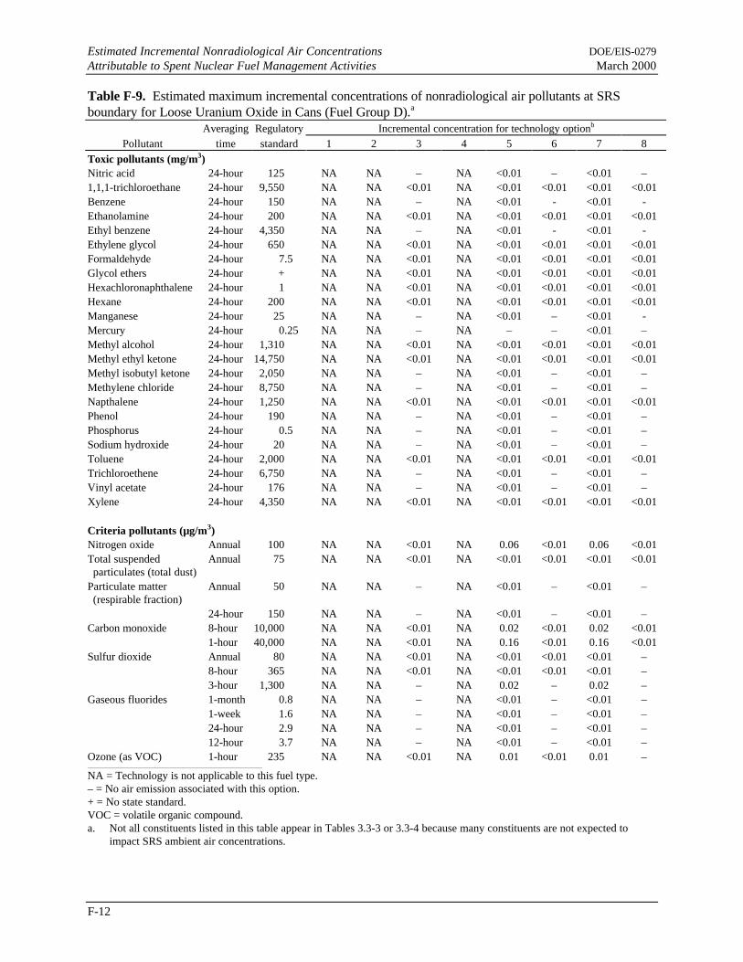
Estimated Incremental Nonradiological Air Concentrations DOE/EIS-0279Attributable to Spent Nuclear Fuel Management Activities March 2000
F-12
Table F-9. Estimated maximum incremental concentrations of nonradiological air pollutants at SRSboundary for Loose Uranium Oxide in Cans (Fuel Group D).a
Averaging Regulatory Incremental concentration for technology optionb
Pollutant time standard 1 2 3 4 5 6 7 8Toxic pollutants (mg/m3)Nitric acid 24-hour 125 NA NA – NA <0.01 – <0.01 –1,1,1-trichloroethane 24-hour 9,550 NA NA <0.01 NA <0.01 <0.01 <0.01 <0.01Benzene 24-hour 150 NA NA – NA <0.01 - <0.01 -Ethanolamine 24-hour 200 NA NA <0.01 NA <0.01 <0.01 <0.01 <0.01Ethyl benzene 24-hour 4,350 NA NA – NA <0.01 - <0.01 -Ethylene glycol 24-hour 650 NA NA <0.01 NA <0.01 <0.01 <0.01 <0.01Formaldehyde 24-hour 7.5 NA NA <0.01 NA <0.01 <0.01 <0.01 <0.01Glycol ethers 24-hour + NA NA <0.01 NA <0.01 <0.01 <0.01 <0.01Hexachloronaphthalene 24-hour 1 NA NA <0.01 NA <0.01 <0.01 <0.01 <0.01Hexane 24-hour 200 NA NA <0.01 NA <0.01 <0.01 <0.01 <0.01Manganese 24-hour 25 NA NA – NA <0.01 – <0.01 -Mercury 24-hour 0.25 NA NA – NA – – <0.01 –Methyl alcohol 24-hour 1,310 NA NA <0.01 NA <0.01 <0.01 <0.01 <0.01Methyl ethyl ketone 24-hour 14,750 NA NA <0.01 NA <0.01 <0.01 <0.01 <0.01Methyl isobutyl ketone 24-hour 2,050 NA NA – NA <0.01 – <0.01 –Methylene chloride 24-hour 8,750 NA NA – NA <0.01 – <0.01 –Napthalene 24-hour 1,250 NA NA <0.01 NA <0.01 <0.01 <0.01 <0.01Phenol 24-hour 190 NA NA – NA <0.01 – <0.01 –Phosphorus 24-hour 0.5 NA NA – NA <0.01 – <0.01 –Sodium hydroxide 24-hour 20 NA NA – NA <0.01 – <0.01 –Toluene 24-hour 2,000 NA NA <0.01 NA <0.01 <0.01 <0.01 <0.01Trichloroethene 24-hour 6,750 NA NA – NA <0.01 – <0.01 –Vinyl acetate 24-hour 176 NA NA – NA <0.01 – <0.01 –Xylene 24-hour 4,350 NA NA <0.01 NA <0.01 <0.01 <0.01 <0.01
Criteria pollutants (µg/m3)Nitrogen oxide Annual 100 NA NA <0.01 NA 0.06 <0.01 0.06 <0.01Total suspendedparticulates (total dust)
Annual 75 NA NA <0.01 NA <0.01 <0.01 <0.01 <0.01
Particulate matter(respirable fraction)
Annual 50 NA NA – NA <0.01 – <0.01 –
24-hour 150 NA NA – NA <0.01 – <0.01 –Carbon monoxide 8-hour 10,000 NA NA <0.01 NA 0.02 <0.01 0.02 <0.01
1-hour 40,000 NA NA <0.01 NA 0.16 <0.01 0.16 <0.01Sulfur dioxide Annual 80 NA NA <0.01 NA <0.01 <0.01 <0.01 –
8-hour 365 NA NA <0.01 NA <0.01 <0.01 <0.01 –3-hour 1,300 NA NA – NA 0.02 – 0.02 –
Gaseous fluorides 1-month 0.8 NA NA – NA <0.01 – <0.01 –1-week 1.6 NA NA – NA <0.01 – <0.01 –24-hour 2.9 NA NA – NA <0.01 – <0.01 –12-hour 3.7 NA NA – NA <0.01 – <0.01 –
Ozone (as VOC) 1-hour 235 NA NA <0.01 NA 0.01 <0.01 0.01 –
NA = Technology is not applicable to this fuel type.– = No air emission associated with this option.+ = No state standard.VOC = volatile organic compound.a. Not all constituents listed in this table appear in Tables 3.3-3 or 3.3-4 because many constituents are not expected to
impact SRS ambient air concentrations.

DOE/EIS-0279 Estimated Incremental Nonradiological Air ConcentrationsMarch 2000 Attributable to Spent Nuclear Fuel Management Activities
F-13
b. Technology options: 1 = Prepare for Direct Disposal/Direct Co-Disposal; 2 = Repackage and Prepare to Ship; 3 = Meltand Dilute; 4 = Mechanical Dilution; 5 = Vitrification Technologies; 6 = Electrometallurgical Treatment; 7 = ConventionalProcessing; and 8 = Continued Wet Storage.

Estimated Incremental Nonradiological Air Concentrations DOE/EIS-0279Attributable to Spent Nuclear Fuel Management Activities March 2000
F-14
Table F-10. Estimated maximum incremental concentrations of nonradiological air pollutants at SRSboundary for Higher Actinide Targets (Fuel Group E).a
Averaging Regulatory Incremental concentration for technology optionb
Pollutant time standard 1 2 3 4 5 6 7 8Toxic pollutants (mg/m3)Nitric acid 24-hour 125 NA – NA NA NA NA NA –1,1,1-trichloroethane 24-hour 9,550 NA <0.01 NA NA NA NA NA <0.01Benzene 24-hour 150 NA - NA NA NA NA NA –Ethanolamine 24-hour 200 NA <0.01 NA NA NA NA NA <0.01Ethyl benzene 24-hour 4,350 NA - NA NA NA NA NA -Ethylene glycol 24-hour 650 NA <0.01 NA NA NA NA NA <0.01Formaldehyde 24-hour 15 NA <0.01 NA NA NA NA NA <0.01Glycol ethers 24-hour + NA <0.01 NA NA NA NA NA <0.01Hexachloronaphthalene 24-hour 1 NA <0.01 NA NA NA NA NA <0.01Hexane 24-hour 900 NA <0.01 NA NA NA NA NA <0.01Manganese 24-hour 25 NA – NA NA NA NA NA –Mercury 24-hour 0.25 NA – NA NA NA NA NA –Methyl alcohol 24-hour 1,310 NA <0.01 NA NA NA NA NA <0.01Methyl ethyl ketone 24-hour 14,750 NA <0.01 NA NA NA NA NA <0.01Methyl isobutyl ketone 24-hour 2,050 NA – NA NA NA NA NA –Methylene chloride 24-hour 515 NA – NA NA NA NA NA –Napthalene 24-hour 1,250 NA <0.01 NA NA NA NA NA <0.01Phenol 24-hour 190 NA – NA NA NA NA NA –Phosphorus 24-hour 0.5 NA – NA NA NA NA NA –Sodium hydroxide 24-hour 50 NA – NA NA NA NA NA –Toluene 24-hour 2,000 NA <0.01 NA NA NA NA NA <0.01Trichloroethene 24-hour 6,750 NA – NA NA NA NA NA –Vinyl acetate 24-hour 176 NA – NA NA NA NA NA –Xylene 24-hour 4,350 NA <0.01 NA NA NA NA NA <0.01
Criteria pollutants (µg/m3)Nitrogen oxide Annual 100 NA – NA NA NA NA NA <0.01Total suspendedparticulates (total dust)
Annual 75 NA – NA NA NA NA NA <0.01
Particulate matter(respirable fraction)
Annual 50 NA – NA NA NA NA NA –
24-hour 150 NA – NA NA NA NA NA –Carbon monoxide 8-hour 10,000 NA – NA NA NA NA NA <0.01
1-hour 40,000 NA – NA NA NA NA NA <0.01Sulfur dioxide Annual 80 NA – NA NA NA NA NA –
8-hour 365 NA – NA NA NA NA NA –3-hour 1,300 NA – NA NA NA NA NA –
Gaseous fluorides 1-month 0.8 NA – NA NA NA NA NA –1-week 1.6 NA – NA NA NA NA NA –24-hour 2.9 NA – NA NA NA NA NA –12-hour 3.7 NA – NA NA NA NA NA –
Ozone (as VOC) 1-hour 245 NA <0.01 NA NA NA NA NA
NA = Technology is not applicable to this fuel type.– = No air emission associated with this option.+ = No state standard.VOC = volatile organic compound.a. Not all constituents listed in this table appear in Tables 3.3-3 or 3.3-4 because many constituents are not expected to
impact SRS ambient air concentrations.

DOE/EIS-0279 Estimated Incremental Nonradiological Air ConcentrationsMarch 2000 Attributable to Spent Nuclear Fuel Management Activities
F-15
b. Technology options: 1 = Prepare for Direct Disposal/Direct Co-Disposal; 2 = Repackage and Prepare to Ship; 3 = Meltand Dilute; 4 = Mechanical Dilution; 5 = Vitrification Technologies; 6 = Electrometallurgical Treatment; 7 = ConventionalProcessing; and 8 = Continued Wet Storage.

Estimated Incremental Nonradiological Air Concentrations DOE/EIS-0279Attributable to Spent Nuclear Fuel Management Activities March 2000
F-16
Direct Disposal, 1, 2, 3, 4, 5, 6, 7, 8, 9, 10Electrometallurgical Treatment, 1, 2, 3, 4, 5, 6,
7, 8, 9, 10Group A, 1, 6Group B, 2, 7Group C, 8
Group D, 4, 9Group E, 5, 10HEU, 8LEU, 8Melt and Dilute, 1, 2, 3, 4, 5, 6, 7, 8, 9, 10uranium, 3, 8

DOE/EIS-0279March 2000 Distribution List
DL-1
DISTRIBUTION LIST
DOE is providing copies of the Final EIS to Federal, state, and local elected and appointed officials andagencies of government; Native American groups; Federal, state, and local environmental and publicinterest groups; and other organizations and individuals listed below. Copies will be provided to otherinterested parties upon request as identified in the coversheet of this Final EIS.
CONTENT
Section Page
A. United States Congress ................................................................................................. DL-2A.1 Senators from Affected and Adjoining States.................................................... DL-2A.2 United States Senate Committees...................................................................... DL-2A.3 United States House of Representatives from Affected and Adjoining States..... DL-2A.4 United States House of Representatives Committees......................................... DL-3
B. Federal Agencies........................................................................................................... DL-3
C. State of South Carolina ................................................................................................. DL-5C.1 Statewide Offices and Legislature..................................................................... DL-5C.2 State and Local Agencies and Officials ............................................................. DL-5
D. State of Georgia ............................................................................................................ DL-5D.1 Statewide Offices and Legislature..................................................................... DL-5
E. Natural Resource Trustees, Savannah River Site............................................................ DL-6
F. Native American Groups............................................................................................... DL-6
G. Environmental and Public Interest Groups..................................................................... DL-6
H. Other Groups and Individuals........................................................................................ DL-8
I. Reading Rooms and Libraries ....................................................................................... DL-12

DOE/EIS-0271Distribution List March 2000
DL-2
A. UNITED STATES CONGRESS
A.1 SENATORS FROM AFFECTED AND ADJOINING STATES
The Honorable Max ClelandUnited States Senate
The Honorable Paul CoverdellUnited States Senate
The Honorable Ernest F. HollingsUnited States Senate
The Honorable Strom ThurmondUnited States Senate
A.2 UNITED STATES SENATE COMMITTEES
The Honorable Mary LandrieuRanking Minority MemberSubcommittee on Strategic ForcesCommittee on Armed Services
The Honorable Robert C. ByrdRanking Minority MemberCommittee on Appropriations
The Honorable Pete V. DomeniciChairmanSubcommittee on Energy and Water
DevelopmentCommittee on Appropriations
The Honorable Carl LevinRanking Minority MemberCommittee on Armed Services
The Honorable Harry ReidRanking Minority MemberSubcommittee on Energy and Water
DevelopmentCommittee on Appropriations
The Honorable Robert SmithChairmanSubcommittee on Strategic ForcesCommittee on Armed Services
The Honorable Ted StevensChairmanCommittee on Appropriations
The Honorable John WarnerChairmanCommittee on Armed Services
A.3 UNITED STATES HOUSE OF REPRESENTATIVES FROM AFFECTED ANDADJOINING STATES
The Honorable James E. ClyburnU.S. House of Representatives
The Honorable Nathan DealU.S. House of Representatives
The Honorable Lindsey GrahamU.S. House of Representatives
The Honorable Jack KingstonU.S. House of Representatives
The Honorable Cynthia McKinneyU.S. House of Representatives
The Honorable Charlie NorwoodU.S. House of Representatives
The Honorable Mark SanfordU.S. House of Representatives
The Honorable Floyd SpenceU.S. House of Representatives
The Honorable John M. Spratt, Jr.U.S. House of Representatives

DOE/EIS-0279March 2000 Distribution List
DL-3
A.4 UNITED STATES HOUSE OF REPRESENTATIVES COMMITTEES
The Honorable Peter ViscloskyRanking Minority MemberSubcommittee on Energy and Water
DevelopmentCommittee on Appropriations
The Honorable Duncan L. HunterChairmanSubcommittee on Military ProcurementCommittee on National Security
The Honorable C. W. Bill YoungChairmanCommittee on Appropriations
The Honorable Ron PackardChairmanSubcommittee on Energy and Water
DevelopmentCommittee on Appropriations
The Honorable David ObeyRanking Minority MemberCommittee on Appropriations
The Honorable Norman SisiskyRanking Minority MemberSubcommittee on Military ProcurementCommittee on National Security
The Honorable Ike SkeltonRanking Minority MemberCommittee on Armed Services
The Honorable Floyd SpenceChairmanCommittee on National Security
B. FEDERAL AGENCIES
Mr. John BellingerNEPA CoordinatorOffice of Environmental PolicyU.S. Army Corps of Engineers
Major General R. M. BunkerDivision Engineer, South Atlantic DivisionU.S. Army Corps of Engineers
Mr. Bill ChampionWest Valley Nuclear ServicesU.S. Department of Energy
Mr. Douglas H. ChapinRichland Operations OfficeU.S. Department of Energy
Mr. Ken ClarkRegion II Public Affairs OfficerU.S. Nuclear Regulatory CommissionCommander, Savannah DistrictAttn: Planning DivisionU.S. Army Corps of Engineers
Ms. Marjorie S. DavenportDistrict ChiefWater Resources DivisionU.S. Geological SurveyU.S. Department of Interior
Mr. Paul F. X. Dunigan, Jr.Richland Operations OfficeU.S. Department of Energy
Mr. Leif EricksonDirectorRichland Operations OfficeU.S. Department of Energy
Mr. Robert FairweatherChief, Environmental BranchOffice of Management and Budget
Dr. Haus MarkAssistant Secretary for Nuclear, Chemical andBiological Defense Programs
DOE/EIS-0271Distribution List March 2000
DL-4
Mr. Joseph R. FranzmathesAssistant Regional Administrator, Office ofPolicy and ManagementU.S. Environmental Protection Agency,
Region IV
Mr. Mark W. FreiOffice of Project CompletionDeputy Assistant SecretaryU.S. Department of Energy
Mr. Kenneth W. HoltCenters for Disease Control and PreventionNational Center for Environmental HealthU.S. Department of Health and Human Services
Mr. Dave HuizengaOffice of Integration and DispositionDeputy Assistant SecretaryU.S. Department of Energy
Mr. Michael JanskyWM HanfordU.S. Department of Energy
Mr. Don L. KlimaDirector, Office of Planning & ReviewAdvisory Council on Historic Prevention
Mr. Andreas Mager, Jr.Habitat Conservation DivisionNational Marine Fisheries ServiceNational Oceanic and Atmospheric
AdministrationU.S. Department of Commerce
Mr. Heinz MuellerOffice of Environmental Policy & ComplianceU.S. Environmental Protection Agency
Mr. Charles OravetzChiefProtected Species Management BranchSoutheast Regional OfficeNational Marine Fisheries ServiceNational Oceanic and Atmospheric
AdministrationU.S. Department of Commerce
Mr. Carl J. PaperielloDirectorNuclear Material Safety SafeguardsU.S. Nuclear Regulatory Commission
Mr. Bob PeraltaChief CouncilArgonne National LaboratoryU.S. Department of Energy Laboratory
Mr. Jon RichardsRegion IVU.S. Environmental Protection Agency
Dr. Libby StullArgonne National LaboratoryU.S. Department of Energy Laboratory
Mr. Willie R. TaylorDirectorOffice of Environmental Policy & ComplianceU.S. Department of Interior
Mr. Greer C. TidwellAdministrator, US EPA-IV
Ms. Kathy WhitakerIdaho Operations OfficeU.S. Department of Energy

DOE/EIS-0279March 2000 Distribution List
DL-5
C. STATE OF SOUTH CAROLINA
C.1 STATEWIDE OFFICES AND LEGISLATURE
The Honorable Jim HodgesGovernor of South Carolina
The Honorable Bob PeelerLieutenant Governor of South Carolina
The Honorable Charles CondonAttorney General
The Honorable James E. Smith, Jr.South Carolina House of Representatives
Ms. Omeaga BurgessOffice of the State Budget
C.2 STATE AND LOCAL AGENCIES AND OFFICIALS
The Honorable Jackie HolmanMayor of Blackville
CoordinatorAiken County Civil DefenseAiken County Emergency ServicesAttn: Freddie M. Bell
Mr. Russell BerrySouth Carolina Department of Health and
Environmental Control
Mr. Frank BrafmanHilton Head Town Council
Mr. Donnie CasonSouth Carolina Department of Highways and
Public Transportation
Ms. Ann ClarkFederal Facility LiaisonEnvironmental Quality ControlSouth Carolina Department of Health and
Environmental Control
Mr. Phil EnglandDirectorAiken County Planning & Development
Department
Mr. G. Kendall TaylorDivision of HydrogeologyBureau of Land and Hazardous Waste
ManagementSouth Carolina Department of Health and
Environmental Control
Mr. David WilsonDivision of HydrogeologyBureau of Land and Hazardous Waste
ManagementSouth Carolina Department of Health and
Environmental Control
D. STATE OF GEORGIA
D.1 STATEWIDE OFFICES AND LEGISLATURE
The Honorable Roy BarnesGovernor of Georgia
The Honorable Mark TaylorLieutenant Governor of Georgia
The Honorable Charles W. WalkerGeorgia Senate
The Honorable Thurbert BakerAttorney General

DOE/EIS-0271Distribution List March 2000
DL-6
The Honorable Ben L. HarbinGeorgia House of Representatives
E. NATURAL RESOURCE TRUSTEES, SAVANNAH RIVER SITE
Mr. Douglas E. BryantCommissioner, SCDHECNatural Resource Trustee
Mr. A. B. GouldDirectorNatural Resource TrusteeDOE-SR Environmental Quality Management
Mr. Clarence HamSRS Natural Resource TrusteeUS Army Corps of EngineersCharleston DistrictDepartment of the Army
Mr. David HolroydSRS Natural Resource TrusteeUS Environmental Protection Agency Region IV
Mr. Ronald W. KinneySRS Natural Resource TrusteeSCDHEC Waste Assessment and EmergencyResponse
Ms. Denise KlimasSRS Natural Resource TrusteeNational Oceanic and AtmosphericAdministrationUS EPA Waste Division
Mr. James H. LeeRegional Environmental OfficerSRS Natural Resource TrusteeUS Department of the Interior
Mr. Douglas L. NovakSRS Natural Resource TrusteeSouth Carolina Office of the Governor
Mr. James SetserChief, Program Coordinator BranchSRS Natural Resource TrusteeDepartment of Natural Resources
Dr. Paul A. SandiferDirectorSC Department of Natural ResourcesSRS Natural Resource Trustee
F. NATIVE AMERICAN GROUPS
The Honorable Gilbert BlueChairmanCatawba Indian Nation
The Honorable Bill FifePrincipal ChiefMuscogee (Creek) Nation
G. ENVIRONMENTAL AND PUBLIC INTEREST GROUPS
Mr. Bill CunninghamEconomistDepartment of Public PolicyAFL-CIO
Ms. Susan GordonProgram DirectorAlliance for Nuclear Accountability
Mr. Brad MorseAlliance for Nuclear Accountability
Ms. Karen PattersonSRS Citizens Advisory Board
Ms. Elizabeth HoinkesGeneral CounselArms Control and Disarmament Agency
Dr. Alan KupermanBrookings Institute

DOE/EIS-0279March 2000 Distribution List
DL-7
Mr. Bennett RambergCommittee to Bridge the Gap
Dr. Arjun MakhijaniPresidentInstitute for Energy and Environmental Research
Mr. Brian CostnerInstitute for Energy and Environmental Research
Dr. Mildred McClainCitizens for Environmental Justice, Inc.
Mr. Paul SchwartzNational Campaigns DirectorClean Water Action
Mr. William YeniscavichDefense Nuclear Facilities Safety Board
Mr. Andrew ThibadeauInformation OfficerDefense Nuclear Facilities Safety Board
Mr. Jim MelilloExecutive DirectorEnvironmental Management Advisory Board
Dr. Brent BlackwelderPresidentFriends of the Earth
Mr. Tom ClementsExecutive DirectorNuclear Control Institute
Mr. David MoglenGreenpeaceWashington, D.C.
Dr. David AlbrightPresidentInstitute for Science and International Security
Dr. David BradleyNational Community Action Foundation
Mr. Robert HoldenExecutive DirectorNational Congress of American Indians
Mr. Alex EcholsDeputy DirectorNational Fish and Wildlife Foundation
Ms. Tamar OstermanDirector of Government AffairsDepartment of Law & Public PolicyNational Trust for Historic Preservation
Mr. Thomas F. DonnellyExecutive Vice PresidentNational Water Resources Association
Mr. Mark Van PuttenPresident & Chief Executive OfficerNational Wildlife Foundation
Dr. Thomas V. CochranDirector, Nuclear ProgramsNatural Resources Defense Council
Dr. Paul LeventhalPresident, Nuclear Control Institute
Dr. Ed LymanScientific DirectorNuclear Control Institute
Mr. Bob TillerDirector of Security ProgramsPhysicians for Social Responsibility
Mr. David CulpPlutonium Challenge
Ms. Joy OakesRegional Staff DirectorAppalachian OfficeThe Sierra Club
Mr. David BeckerThe Sierra Club
Mr. Tom Zamora CollinaDirector of Arms Control ProjectUnion of Concerned Scientists

DOE/EIS-0271Distribution List March 2000
DL-8
Ms. Diane JacksonAdministrative AssistantEcology and Economics Research DepartmentThe Wilderness Society
Ms. Rebecca CharlesTennessee Department of Environment andConservation
H. OTHER GROUPS AND INDIVIDUALS
Mr. Peter Allan
Dr. Dave AmickSAIC
Mr. Tom AndersonBattelle
Ms. Margaret AokiNINNHO IWAI American Corporation
Ms. Jila BanaeeLockheed-Martin Idaho Technologies Company
Mr. Sy BaronMUSC
Ms. Sonya Barnette
Mr. James R. BarrettB&W Services, Inc.
Colonel Mary Barton
Mr. Robert C. Baumback
Ms. Lisa BaxterGeorgia Technical College
Mr. W. Alton Bell, Jr.Plumbers & Steamfitters Local Union #150
Mr. Charles T. Black
Mr. Edward P. Blanton, Jr.
Mr. Edmund D. BootheAiken Technical College
R. P. Borsody
Mr. Carlos W. Bowen
Ms. Sara Jo Braid
Mr. Dannion Brinkley
Mr. Bill Brizes
Ms. Elizabeth R. BrownCharleston DeanerySouth Carolina Council of Catholic Women
Mr. Ethan Brown
Mr. Ken Bulmahn
Ms. Donna CampbellFoster Wheeler Environmental Corporation
Mr. Rich CampbellChem-Nuclear Systems
Mr. Roy Carter
Mr. George R. Caskey
Dr. Kailash Chandra
Mr. Ernie Chaput
Mr. Vladimir Y. ChechikShaw, Pitman, Potts, & Trowbridge
Mr. Carl E. Cliche
Ms. Marlena CondeEdlow International Company
Mr. Steve Connor
Mr. S. W. Corbett
Mr. Stephen Crump

DOE/EIS-0279March 2000 Distribution List
DL-9
Dr. Tim DevolClemson UniversityEnvironmental Systems Engineering Department
Mr. Sal Dimaria
Mr. John Dimarzio
Mr. John F. Doherty, J.D.
Mr. Dave Ecklund
Mr. Richard EngelmannWaste Management Hanford
Ms. Lynne Fairobent
Ms. Rita FellersDepartment of GeographyUniversity of North Carolina at Chapel Hill
Mr. Leverne P. Fernandez
Mr. Ken Fitch
Ms. Bonnie FogdallSAIC
Professor H. Paul FriesemaInstitute for Policy and ResearchNorthwestern University
Mrs. Nadia FrilouxCOGIMA Inc.
Mr. Richard FryDirector, Division of Radiation Protection
Mr. Melvyn P. Galin
Mr. Ben Gannon
Mr. John Geddie
Colonel George A. Gibson
Mr. Robert GodfreyCounselor (Nuclear)Embassy of Australia
Mr. Anthony P. Gouge
Dr. Randall GuenslerSchool of Civil & Environmental EngineeringGeorgia Institute of Technology
Mr. Robert Guild
Mr. Jan Hagers
Mr. David Haines
Ms. Mary Hassell
Ms. Kathryn Hauer
Ms. Cathy Haupt
Ms. Shelley HawkinsJacobs Engineering Group, Inc.
Mr. Warren HillsLaborers Local 1137AFL-CIO
Mr. C. C. Holcomb
Mr. Robert A. Hollingsworth
Mr. Leonard Huesties
Mr. Charles E. Irvin
Mr. Cliff Jarman
Mr. Keith JohnsonINEEL, CAB
Mr. Norman Kaish
Mr. Roy Karimi
Mr. Tim Kimball
Mr. Ron KollWaste Management Services
Mr. Larry Kripps
Dr. Wilfried Krull
Mr. Paul KrzychDynamic Corporation

DOE/EIS-0271Distribution List March 2000
DL-10
Miss Cynthia E. Lake
Mr. Dewey E. LargeMolten Metal Technology Inc. of TNMr. Lechel
Mr. Thomas L. Lippert
Dr. William A. LochstetUniversity of Pittsburgh at Johnstown Physics
Mr. Alastair J. MacDonaldUKAEA
Mr. Robert Maher
Mr. Steve Maheras
Dr. Gary MarshallES&H Program Control ManagerArgonne Medical Laboratory-West
Mr. Joseph A. MartillottiTexas Department of HealthBureau of Radiation Control
Mr. Bob Matthews
Ms. Elizabeth McBride
Ms. Trish McCracken
Dr. William R. McDonell
Mr. Michael F. McGowanGeological Environmental Consultant
Ms. Dana McIntyreWJBF-TVChannel 6
Mr. Frank Metz
Ms. Louise M. Montgomery
Mr. Emment MooreWashington State University
Mr. Kenneth J. Newcomer
Ms. Kim NewellPublic Information DirectorSCDHEC
Mr. R. I. Newman
Mr. David Nichols
Ms. Suzanne Ochse
Mr. Matthew J. O’Connor
Mr. James L. Oliver
Mr. J. F. Ortaldo
Mr. Robert F. Overman
Mr. Aris Papadopoulous
Ms. Jean Pasquale
Dr. Ruth PatrickDivision of Limnology and EcologyAcademy of Natural Sciences of Philadelphia
Mr. Mark A. PetermannHydrogeologistRMT, Inc.
Mr. Jeff Petraglia
Mr. George Piper
Mr. David Pittman
Mr. W. Lee Poe
Mr. Ron PoundEnvironmental ProjectsNewsletter
Mr. Richard H. Powell
Ms. Essie M. RichardsCarver Heights Community Org.
Ms. Dorene L. Richardson
Mr. Wayne RickmanSonalysts, Inc.
DOE/EIS-0279March 2000 Distribution List
DL-11
Mr. F. A. Riemann
Mr. Jacob Charles Robertson
Mr. Paul RobinsonSouthwest Research & Information Center
Ms. Linda Rodgers
Ms. Connie Rogers
Mr. Edward Scalsky
Mr. Glenn R. Schlafer
Mr. Guy R. Selph
Dr. R. F. Shangraw, Jr.Project Performance Corporation
Ms. Margaret ShekellUltra Systems Environmental
Mr. John O. Shipman
Ms. Kimberly Sizemore
Mr. Jim Skinner
Mr. Donald J. Skinner
Mr. Arthur H. Smith, Jr.
Mr. Don SolkiCarpenter’s Local 283
Mr. Paul StansburyPNL
Mr. Jim SteinkeNewport News Shipbuilding Co.
Mr. Bill StokesAdvanced Nuclear and Medical Systems
The Reverend Thomas A. Summers
Mr. Arthur SutherlandRogers & Associates Engineering Corporation
Mr. Edward S. Syrjala
Dr. D. William TedderAssociate ProfessorSchool of Chemical EngineeringGeorgia Institute of Technology
Mr. James W. TerryOak Ridge National LaboratoryLockheed Martin Energy Research
Mr. Vincent Van BruntUniversity of South CarolinaChemical Engineering Department
Ms. Linda Van SickleExploration Resources
Mr. Alan VaughanNuclear Fuel Services
Mr. Martin VorumCommodore Advanced Sciences, Inc.
Ms. Melissa VranaProject Performance Corporation
Mr. Jim Wanzeck
Mr. Payton H. Ward, Jr.Ironworkers Local Union #709
Mr. Edgar WestIronworkers Local Union #709
Mr. Frank S. Watters
Mr. Kim Welsch
Dr. F. Ward WhickerRadiological Health ServicesColorado State University
Ms. Reba WhiteTeladine Brown Engineering, Inc.
Ms. Pam WhitsonOak Ridge Associated Universities
Mr. Patrick L. Whitworth
DOE/EIS-0271Distribution List March 2000
DL-12
Mrs. Debbie Wilcox
Mr. Don J. WilkesJacob Engineering Group
Mr. Jermetia L. Williams
Mr. Michael Witunski
Mr. Mel Woods
Dr. Abe ZeitounSAICMr. Francis P. ZeraThe Georgia Guardian
I. READING ROOMS AND LIBRARIES
Freedom of Information Public Document RoomUniversity of South Carolina at Aiken SCGregg-Graniteville Library
Freedom of Information Reading RoomU.S. Department of Energy
Battelle-Pacific Northwest LaboratoriesAttn: Technical Library
LibrarianChatham-Effingham-Liberty Regional Library
LibrarianLos Alamos Technical Association
Head, Document DepartmentThe LibrariesColorado State University
LibrarianErskine CollegeMcCain Library
Parsons Brinckerhoff Library
Public Reading RoomChicago Operations Office
Mr. Michael SimpsonLibrary of Congress
Ms. Judy SmithMonographs Acquisition ServicesColorado State Universities Libraries
Felicia YehTechnical Services LibrarianSouth Carolina State Library
LibrarianSavannah River Site LibrarySavannah River Technology Center
LibrarianWestinghouse Savannah River Company
Library776-H
LibrarianOrangeburg County Free Library
LibrarianSouth Carolina State LibraryColumbia, SC
LibrarianTechnical LibraryArgonne National Laboratory
LibrarianGeorgia Institute of Technology Library
LibrarianPullen Public LibraryAtlanta, GA
LibrarianFreedom of Information Act (FOIA) Reading
RoomDOE-Albuquerque Operations Office
Public Reading RoomDOE Oak Ridge Operations Office
LibrarianReese LibraryAugusta College

DOE/EIS-0279March 2000 Distribution List
DL-13
LibrarianCounty LibraryCharleston, SC
LibrarianGovernment Information DepartmentZimmerman LibraryUniversity of New Mexico
Public Reading RoomRichland, WA
Public Reading RoomIdaho National Engineering and Environmental
Laboratory
DOE/EIS-0279March 2000 Glossary
GL-1
GLOSSARY
°CDegree Celsius. A temperature scale commonly used in scientific work based on the freezing pointof water at 0°C and the boiling point at 100°C under normal atmospheric pressure.
°C = 59 × (°F - 32).
°FDegree Fahrenheit. A temperature scale based on the freezing point of water at 32°F and the boil-
ing point at 212°F under normal atmospheric pressure. °F = (°C × 95) + 32.
absorbed doseThe energy deposited per unit mass by ionizing radiation. The unit of absorbed dose is the rad.
accidentOne or more unplanned events involving materials that have the potential to endanger the healthand safety of workers and the public. An accident can involve a combined release of energy andhazardous materials (radiological or chemical) that might cause prompt or latent adverse health ef-fects.
actinideAny of a series of chemically similar, mostly synthetic, radioactive elements with atomic numbersranging from actinium at 89 through lawrencium at 103.
air quality standardsThe prescribed level of constituents in the outside air (ambient air) that legally should not be ex-ceeded during a specified unit of time in a specified area.
alpha (α) particleA positively charged particle consisting of two protons and two neutrons that is emitted from thenucleus of certain nuclides during radioactive decay. It is the least penetrating of the three com-mon types of radiation (alpha, beta, and gamma).
aqueousRelating to or made with water.
aquiferA geologic formation that contains enough saturated porous material to permit groundwater tomove through it and to yield worthwhile quantities of groundwater to wells and springs.
As Low As Reasonably Achievable (ALARA)An approach to radiation protection that controls or manages exposures (both individual and col-lective to workers and general public) as low as social, technical, economic, practical and publicpolicy considerations permit. ALARA is not a dose limit, but a process which has the objective ofdose levels as far below applicable limits of 10 CFR 835 as is reasonably achievable. Particularattention is to be paid to this definition in design of facilities.

DOE/EIS-0279Glossary March 2000
GL-2
atomic weightThe relative weight of an atom of a chemical element based on the weight of the most abundantisotope of carbon, which is taken to be 12.
AXAIRQA computer model that analyzes doses from airborne radionuclide releases.
background exposureSee exposure to radiation.
background radiationNormal radiation present in the lower atmosphere from cosmic rays and earth sources. Back-ground radiation varies with location, depending on altitude and natural radioactivity present in thesurrounding geology.
Best Management Practices (BMP)A practice or combination of practices that is determined by a state (or other planning agency) tobe the most effective, practicable means of preventing pollution generated by nonpoint sources orof reducing it to a level compatible with air or water quality goals.
beta (β) particleAn elementary particle emitted from a nucleus during radioactive decay. It is negatively charged,identical to an electron, and easily stopped by a thin sheet of metal.
biotaLiving organisms.
blackwaterWater in Coastal Plain creeks, swamps, and rivers that has a dark or black coloration due to dis-solution of naturally-occurring organic matter from soils and decaying vegetation.
bounding accidentAn accident whose calculated consequences encompass all other possible accident consequencesfor that facility. For example, a bounding accident for the release of hazardous material from astorage tank would postulate the release of the entire tank contents. The consequences from thisaccident would be greater than the consequences of all other tank release accidents.
brownfieldAn area that has been previously disturbed by industrial activities.
burnIrradiation of fuel in a nuclear reactor with the resultant production of energy, neutrons, and fissionproducts.
burnupThe total energy released through fission by a given amount of nuclear fuel; generally measured inmegawatt-days.

DOE/EIS-0279March 2000 Glossary
GL-3
cancerA malignant tumor of potentially unlimited growth, capable of invading surrounding tissue orspreading to other parts of the body by metastasis.
canisterA stainless-steel container in which nuclear material is sealed.
canyonA heavily shielded building where radioactive materials are chemically processed to recover specialisotopes for national defense or other programmatic purposes. In the canyon, operation and main-tenance are remotely-controlled.
capable (geology)Describes a geological fault that has moved at or near the ground surface within the past35,000 years.
carcinogenAn agent capable of inducing cancer.
carcinogenicCapable of inducing cancer.
caseThe application of a given technology to a single fuel group.
caskA massive, heavily-shielded container for holding nuclear materials during shipment.
cesiumNaturally occurring element with 55 protons in its nucleus. Some manmade isotopes of cesium areradioactive (e.g., cesium-134, cesium-137).
claddingThe outer jacket of fuel elements and targets, usually made of aluminum, stainless steel, or zirco-nium-aluminum alloy; used to prevent fuel corrosion and retain fission products during reactor op-eration, or to prevent radioactive releases into the environment during storage.
co-disposalA disposal approach for spent nuclear fuel in a geologic repository. Five canisters of high-levelwaste would fit in a repository waste package, with room for one 17-inch (43-centimeter) diametercanister of spent nuclear fuel.
collective doseThe sum of the individual doses to all members of a specific population.
committed dose equivalentThe calculated dose equivalent received by a tissue or an organ during the 50-year period after aradionuclide is introduced into the body.
DOE/EIS-0279Glossary March 2000
GL-4
committed effective dose equivalentThe sum of the committed dose equivalents to various tissues/organs in the body multiplied by theirappropriate tissue weighting factor. Equivalent in effect to a uniform external dose of the samevalue.
community (environmental justice)A group of people or a specific location exposed to risks that potentially threaten health, ecology,or land values, or exposed to industry that stimulates unwanted noise, smell, industrial traffic, par-ticulate matter, or other nonaesthetic impacts.
concentrationThe amount of a substance contained in a unit quantity of material.
confining unitA body of impermeable or distinctly less-permeable material stratigraphically adjacent to one ormore aquifers.
consequenceThe result or effect (especially projected exposure to radiological or chemical hazards) of a releaseof hazardous materials to the environment.
constituentsParts or components of a whole.
criticalDescribing the condition when fissile materials exposed to neutron bombardment produce enoughneutrons to support a chain reaction.
criticalityA state in which a self-sustaining nuclear chain reaction is achieved.
cropA process that cuts off or otherwise removes the hardware on the fuel assemblies, leaving primarilythe active fuel for subsequent processes.
cumulative impactsAdditive impacts on the environment including ecological, human health, or socioeconomic effectsthat result from the addition of the impact of the proposed action to impacts from other past, pres-ent, and reasonably foreseeable future actions regardless of what agency (Federal or non-Federal)or person undertakes the other actions (40 CFR 1508.7).
curie (Ci)A unit of radioactivity equal to 37,000,000,000 disintegrations per second (or becquerels).
daughterA nuclide formed by the radioactive decay of another nuclide, which is the “parent.”

DOE/EIS-0279March 2000 Glossary
GL-5
decay heatThe radioactive decay of fission products can produce very high temperatures (decay heat), whichis why fuel recently removed from a reactor is placed in underwater storage for cooling. Withoutactive cooling, the fuel could overheat and melt or damage the cladding. After a sufficient coolingtime that depends on the burnup of the fuel and its composition, fuel assemblies can be stored dry.Dry fuel storage technologies must consider decay heat.
decay, radioactiveThe spontaneous transformation of one nuclide into a different nuclide or into a different energystate of the same nuclide. The process results in the emission of nuclear radiation (usually alpha,beta, or gamma radiation).
decibelA unit for measuring the relative loudness of sounds. In general, a sound doubles in loudness forevery increase of 10 decibels.
decision makerGroup or individual responsible for making a decision on a particular proposed action. Decisionmakers include DOE officials as specified in DOE Order 451.1A; elected officials; Federal, state,and local agency representatives; and the public.
decommissioningThe removal from service of facilities such as processing plants, waste tanks, and burial grounds,and the reduction or stabilization of radioactive contamination. Decommissioning includes decon-tamination, dismantling, and return of the area to original condition without restrictions or partialdecontamination, isolation of remaining residues, and continuation of surveillance and restrictions.
Defense Waste Processing FacilitySavannah River Site facility that processes high-level radioactive waste into a glass form for trans-port to a permanent disposal site.
deflagrationRapid burning with great heat and intense light.
demographicRelated to the statistical study of human populations, including size, density, distribution, and vitalstatistics such as age, gender, and ethnicity.
depleted uraniumA mixture of uranium isotopes where uranium-235 represents less than 0.7 percent of the uraniumby mass.
derived concentration guide (DCG)The concentration of a radionuclide in air or water that, under conditions of continuous exposurefor one year by one exposure mode (i.e., ingestion of water, submersion in air, or inhalation),would result in an effective dose equivalent of 100 mrem (0.1 rem = 1 mSv [milliSievert]).
disassociateSeparate chemicals into their elemental or ionic state.

DOE/EIS-0279Glossary March 2000
GL-6
doseThe energy imparted to matter by ionizing radiation. The unit of absorbed dose is the rad, equal to0.01 joule per kilogram of irradiated material in any medium.
dose conversion factorFactor used to calculate the dose received from exposure to radiation.
dose equivalentA term used to express the amount of effective radiation when modifying factors have been consid-ered. It is the product of absorbed dose (rads) multiplied by a quality factor and other modifyingfactors. It is measured in rem (Roentgen equivalent man).
dose rateThe radiation dose delivered per unit time (e.g., rem per year).
ecologyThe science that deals with the relationship of living things with each other and with their environ-ment.
ecosystemA complex of the communities of living things and their environment which forms a functioningwhole in nature.
effective dose equivalentA quantity used to estimate the biological effect of ionizing radiation. It is the sum over all bodytissues of the product of absorbed dose, the quality factor (to account for the different penetratingabilities of the various radiations), and the tissue weighting factor (to account for the different ra-diosensitivity of the various tissues of the body).
effective porosityA property of earth containing interconnecting interstices, expressed as a percent of bulk volumeoccupied by the interstices.
effluentLiquid or airborne material released to the environment. In general usage, however, effluent im-plies liquid releases.
electronAn elementary particle with a mass of 9.107×10⁻²⁸ gram (or 1/1837 of a proton) and a negativecharge. Electrons surround the positively charged nucleus and determine the chemical propertiesof the atom.
elementOne of the 109 known chemical substances that cannot be divided into simpler substances bychemical means. All isotopes of an element have the same atomic number (number of protons) buthave different numbers of neutrons.
Emergency Response Planning Guideline (ERPG) valuesThese values, which are specific for each chemical, are established for three general severity levels:exposure to concentrations greater than ERPG-1 values for a period of time greater than 1 hour re-

DOE/EIS-0279March 2000 Glossary
GL-7
sults in an unacceptable likelihood that a person would experience mild transient adverse health ef-fects, or perception of a clearly defined objectionable odor; exposure to concentrations greater thanERPG-2 values for a period of time greater than 1 hour results in an unacceptable likelihood that aperson would experience or develop irreversible or other serious health effects, or symptoms thatcould impair one’s ability to take protective action; exposure to concentrations greater than ERPG-3 values for a period of time greater than 1 hour results in an unacceptable likelihood that a personwould experience or develop life-threatening health effects.
emission standardsLegally enforceable limits on the quantities and kinds of air contaminants that may be emitted tothe atmosphere.
endangered speciesPlants or animals that are in danger of extinction through all or a significant portion of their rangesand that have been listed as endangered by the U.S. Fish and Wildlife Service or the National Ma-rine Fisheries Service.
energyThe capacity to produce heat or do work.
enrichmentA process in which the fraction of the uranium-235 isotope has been artificially increased abovethe natural abundance level of 0.72 percent.
environmentThe sum of all external conditions and influences affecting the life, development, and ultimately thesurvival of an organism.
environmental impact statement (EIS)A detailed written statement as required by Section 102(2)(c) of the National Environmental PolicyAct (NEPA) of 1969, as amended, to assess the environmental impacts of major Federal actions.
environmental justiceThe fair treatment of people of all races, cultures, incomes, and educational levels with respect tothe development, implementation, and enforcement of environmental laws, regulations, and poli-cies. Fair treatment implies that no population of people should be forced to shoulder a dispropor-tionate share of the negative environmental impacts of pollution or environmental hazards due to alack of political or economic strength.
exposure to radiationThe incidence of radiation on living or inanimate material by accident or intent. Background expo-sure is the exposure to natural background ionizing radiation. Occupational exposure is the expo-sure to ionizing radiation that occurs at a person’s workplace. Population exposure is the exposureto a number of persons who inhabit an area.
external initiatorsAccidental occurrences that are independent of facility operations and normally originate outsidethe facility (aircraft crashes, nearby explosions, and toxic chemical releases at nearby facilities that

DOE/EIS-0279Glossary March 2000
GL-8
affect worker performance); some can affect the ability of the facility to maintain confinement ofhazardous materials because of structural damage.
faultA fracture or a zone of fractures within a rock formation along which vertical, horizontal, or trans-verse slippage of the earth’s crust has occurred in the past.
fertileDescribing radionuclides that can be converted into fissile material (e.g., thorium-232 and ura-nium-238 can be converted through neutron capture to uranium-233 and plutonium-239, respec-tively).
fissileCapable of being split or divided (fissioned) by the absorption of thermal neutrons. The mostcommon fissile materials are uranium-233, uranium-235, and plutonium-239.
fissionThe splitting of a heavy nucleus into two approximately equal parts, which are nuclei of lighterelements, accompanied by the release of energy and generally two or more neutrons. Fission canoccur spontaneously or can be induced by nuclear bombardment.
fission chain reactionNuclear reaction in which atomic nuclei in reactor fuel respond to collisions with neutrons by split-ting into two or three major fragments and additional neutrons accompanied by the emission ofgamma radiation.
fission fragmentsThe parts into which atomic nuclei in reactor fuel split during a fission chain reaction.
fission productsNuclei from the fission of heavy elements (primary fission products); also, the nuclei formed by thedecay of the primary fission products, many of which are radioactive.
gamma (γ) raysHigh-energy, short-wavelength electromagnetic radiation accompanying fission, radioactive decay,or nuclear reactions. Gamma rays are very penetrating and require relatively thick shields to ab-sorb the rays effectively.
geologyThe science that deals with the earth: the materials, processes, environments, and history of theplanet, especially the lithosphere, including the rocks, their formation and structure.
groundwaterThe supply of fresh water below the earth’s surface in an aquifer.
habitatThe place or type of site where a plant or animal normally grows or lives.

DOE/EIS-0279March 2000 Glossary
GL-9
half-life (radiological)The time in which half the atoms of a radioactive substance disintegrate to another nuclear form.Half-lives vary from millionths of a second to billions of years.
hazardous materialA substance or a material including a hazardous substance that has been determined by the U.S.Secretary of Transportation to be capable of posing an unreasonable risk to health, safety, andproperty when transported in commerce.
hazardous substanceAny substance that when released to the environment in an uncontrolled fashion could be harmfulto the biota or human health and when released in an unpermitted fashion becomes subject to thereporting and possible response provisions of the Clean Water Act and the Comprehensive Envi-ronmental Response, Compensation, and Liability Act.
hazardous wasteWaste that is regulated under the Resource Conservation and Recovery Act and correspondingstate regulations. Waste is hazardous if the EPA lists it as such or if it exhibits the characteris-tic(s) of ignitability, corrosivity, reactivity, or toxicity. SRS hazardous waste streams consist of avariety of materials, including mercury, chromates, lead, paint solvents, and various laboratorychemicals.
heavy metalIn this document, heavy metal refers to materials of high atomic number that were placed in nu-clear reactors. This includes thorium, uranium, and plutonium.
high efficiency particulate air (HEPA) filterA type of filter designed to remove 99.95 percent of the particles down to 0.3 micrometer in di-ameter from a flowing air stream.
high(ly) enriched uraniumUranium that is equal to or greater than 20 percent uranium-235 by weight. Many of the fuels dis-cussed in this EIS are based primarily on highly enriched uranium.
high-level radioactive wasteHighly radioactive material from the processing of spent nuclear fuel that contains a combinationof transuranic waste and fission products in concentrations that require permanent isolation. It in-cludes both liquid waste produced by processing and solid waste derived from that liquid.
hydraulic conductivityThe rate of water flow in gallons pre day through a cross-section of 1 square foot under a unit hy-draulic gradient, also known as permeability coefficient.
hydraulic gradientWith regard to an aquifer, the rate of change of pressure head per unit distance of flow at a givenpoint and in a given direction.
infrastructureThe system of public works of a county, state, or region; also, the resources (buildings or equip-ment) required for an activity.

DOE/EIS-0279Glossary March 2000
GL-10
interim storageSafe and secure storage for spent nuclear fuel and radioactive wastes until the materials are dispo-sitioned (treatment and/or disposal).
internal initiatorsEvents that normally originate in and around the facility but are always a result of facility opera-tions (equipment or structural failures, human errors, internal flooding). In accident scenarios, ini-tiators start the events that culminate in a release of hazardous or radioactive materials.
involved workerAn individual located in the facility under discussion.
ionAn atom or molecule that has gained or lost one or more electrons to become electrically charged.
ionizing radiationRadiation capable of ejecting electrons from atoms or molecules to produce ions.
irradiationExposure to radiation.
isotopeAn atom of a chemical element with a specific atomic number and atomic weight. Isotopes of thesame element have the same number of protons but different numbers of neutrons (i.e., the sameatomic number, but different mass numbers). Isotopes are identified by the name of the elementand the total number of protons and neutrons in the nucleus. For example, plutonium-239 is aplutonium atom with 239 protons and neutrons.
isotopic dilutionMixing a less-enriched radioisotope with a highly enriched radioisotope to yield an isotope withlower nuclear enrichment.
latent cancer fatalitiesDeaths resulting from cancers that became active sometime after the exposure presumed to haveinduced them.
long-lived radionuclidesRadioactive isotopes with half-lives greater than about 30 years.
low-enriched uranium (LEU)Uranium with uranium-235 enriched above the natural concentration (0.72 percent) but below20 percent; highly enriched uranium (HEU) is enriched 20 percent or higher.
low-income communityA community where 25 percent or more of the population is identified as living in poverty.

DOE/EIS-0279March 2000 Glossary
GL-11
low-level mixed wasteRadioactive waste that contains material listed as hazardous under the Resource Conservation andRecovery Act or that exhibits one or more of the following hazardous waste characteristics: ig-nitability, corrosivity, reactivity, or toxicity. It includes such materials as tritiated mercury, triti-ated oil contaminated with mercury, other mercury-contaminated compounds, or radioactively-contaminated lead shielding.
low-level radioactive wasteRadioactive waste that cannot be classified as high-level waste, spent nuclear fuel, transuranicwaste, or byproduct material, and that does not have any constituents that are regulated under theResource Conservation and Recovery Act.
materials test reactor equivalent (MTRE)A quantity of spent nuclear fuel related to its volume that provides information on the amount ofstorage space provided.
MAXIGASPA computer program used to calculate doses of airborne releases of radioactivity to the maximallyexposed member of the public.
maximally exposed individualA hypothetical person located to receive the maximum possible dose by a given exposure scenario.
maximum contaminant levels (MCLs)The maximum permissible level of a contaminant in water that is delivered to a user of a publicwater system.
metric tons of heavy metal (MTHM)Quantities of unirradiated and spent nuclear fuel and targets are traditionally expressed in terms ofmetric tons of heavy metal (typically uranium) without the inclusion of other materials such ascladding, alloy materials, and structural materials. A metric ton is 1,000 kilograms, which is equalto about 2,200 pounds.
migrationThe natural travel of a material through the air, soil, or water.
milliremOne thousandth of a rem. (See rem.)
minority communityA person classified by the U.S. Bureau of the Census as Black, Hispanic, Asian and Pacific Is-lander, American Indian, Eskimo, Aleut, or other nonwhite persons is considered a minority. Acommunity with the number of minority persons equal to or greater than the minority average of adefined area or jurisdiction (usually a state) is a minority community.
moderationProcess for slowing down neutrons resulting from fission or other nuclear reactions; slow or“thermal” neutrons are necessary for sustaining a fission chain reaction in fissile materials; waterand heavy water are common moderators.

DOE/EIS-0279Glossary March 2000
GL-12
monitoringContinuing control and accountability, particularly of special nuclear materials such as plutonium-239 and highly enriched uranium, but also including oversight of hazardous or reactive compoundsbefore they are disposed of or converted to a stable long-term storage form.
National Ambient Air Quality StandardsAir quality standards established by the Clean Air Act, as amended in 1990. The primary NationalAmbient Air Quality Standards are intended to provide the public with an adequate margin ofsafety, and the secondary National Ambient Air Quality Standards are intended to protect the pub-lic from known or anticipated adverse impacts of a pollutant.
National Pollutant Discharge Elimination SystemFederal system that permits liquid effluents regulated through the Clean Water Act, as amended.
natural phenomena initiatorsNatural occurrences that are independent of facility operations and events at nearby facilities oroperations (earthquakes, high winds, floods, lightning, snow). Although these initiators are inde-pendent of external facilities, they can affect such facilities and compound the progression of theaccident.
natural radiation or natural radioactivityBackground radiation. Radiation arising from cosmic and terrestrial naturally-occurring radionu-clide sources.
National Environmental Policy Act (NEPA)The National Environmental Policy Act of 1969 (42 USC 4321) requires the preparation of an EISfor Federal projects that could incur significant impacts to the environment.
neutronAn elementary nuclear particle capable of inducing a fission chain reaction in certain atomic nuclei,including uranium-235.
neutron poisonA substance that absorbs neutrons without causing a fission, thereby preventing nuclear criticali-ties.
noninvolved workerFor this EIS, an SRS worker who is not involved in a given operation or activity.
nonproliferationThe restriction of access to fissile materials in concentrations sufficient to assemble a nuclearweapon.
Nuclear Regulatory CommissionThe independent Federal commission that licenses and regulates commercial nuclear facilities.
nuclear radiationRadiation, usually alpha, beta, or gamma, that emanates from an unstable atomic nucleus.

DOE/EIS-0279March 2000 Glossary
GL-13
nuclear reactionAn interaction between a photon, particle, or nucleus and a target nucleus, leading to transmuta-tion.
nuclear reactorA device in which a fission chain reaction is maintained, used for the irradiation of materials or thegeneration of electricity.
nuclideA species of atom characterized by the number of protons, number of neutrons and by energy con-tent in the nucleus; a radionuclide is a radioactive nuclide.
offsite populationDefined as all individuals located within an 80-kilometer (50-mile) radius of a facility with poten-tial to emit radioactive material.
organic compoundsChemical compounds containing hydrocarbons.
ozoneA compound of oxygen in which three oxygen atoms are chemically attached to each other.
oxides of nitrogen (NOx)Primarily nitrogen oxide (NO) and nitrogen dioxide (NO2), these compounds are produced in thecombustion of fossil fuels, and contribute to air pollution.
particulatesSolid particles and liquid droplets small enough to become airborne.
passivationTo reduce the reactivity of a chemically-active metal.
pelletsOne configuration of the reactive material in a target rod.
permeabilityA measure of a material’s ability to have liquids or gases passes through it via pores or openings.
person-remThe radiation dose to a given population; the sum of the individual doses received by a population.
plutonium (Pu)A transuranic, heavy (average atomic mass about 244 atomic mass units), silvery metal with15 known isotopes that is produced by the neutron irradiation of natural uranium. Plutonium-239is used both in nuclear weapons and commercial nuclear power applications. Plutonium-238 isused to power onboard electric generators during manned and unmanned space flights.
poisonA material that has an affinity for absorbing neutrons. Poisons are added to nuclear materials witha potential criticality concern to lessen the likelihood of an uncontrolled nuclear reaction.

DOE/EIS-0279Glossary March 2000
GL-14
pollutionThe addition of an undesirable agent to an ecosystem in excess of the rate at which natural proc-esses can degrade, assimilate, or disperse it.
POPGASPA computer model used to calculate doses of airborne releases of radioactivity to the populationwithin 80 kilometers (50 miles) of the SRS.
populationIn this EIS, a collection of members of the public that is located outside the boundaries of the SRS.Impacts in this EIS are estimated for the population within a given area, depending on the appro-priate environmental pathways. For example, the affected population for liquid releases to the Sa-vannah River includes downstream residents.
Prevention of Significant Deterioration (PSD)A standard that establishes the acceptable amount of deterioration in air quality. When the airquality of an area meets the standards for a specific pollutant, the area is declared to be in attain-ment for that pollutant. When the air quality of an area does not meet the standard for a specificpollutant, the area is said to be in nonattainment for that pollutant. PSD requirements definemaximum allowable increases (increments) in ambient air pollutant concentrations (sulfur dioxide,particulate, nitrogen oxide) for construction or modification of facilities which by definition do not“significantly deteriorate” the existing baseline air quality.
processing (of spent nuclear fuel)Applying a chemical or physical process designed to alter the characteristics of the spent fuel ma-trix.
production well/waterAt the SRS, water treated and used as potable water.
programmatic materialsStable nuclear materials with value for supporting national programs (e.g., plutonium-238 produc-tion for the National Aeronautics and Space Administration).
protonA nuclear particle with a positive charge equal in magnitude to the negative charge of the electron;it is a constituent of all atomic nuclei, and the atomic number of an element indicates the number ofprotons in the nucleus of each atom of that element.
pyrophoricThe tendency to spontaneously ignite in air. Some uranium and thorium metal fuels may be pyro-phoric.
radiationThe emitted particles and photons from the nuclei of radioactive atoms; a shortened term for ion-izing radiation or nuclear radiation as distinguished from nonionizing radiation (microwaves, ultra-violet rays, etc.).

DOE/EIS-0279March 2000 Glossary
GL-15
radiation shieldingRadiation-absorbing material that is interposed between a source of radiation and organisms thatwould be harmed by the radiation (e.g., people).
radioactive wasteWaste that has radioactive material and must be handled as such.
radioactivityThe spontaneous decay of unstable atomic nuclei, accompanied by the emission of radiation.
radioisotopeRadioactive isotopes. The isotopes of an element that are radioactive. Not all isotopes of a singleelement are radioactive. Some radioisotopes are naturally occurring (e.g., potassium-40) whileothers are produced by nuclear reactions.
radiolysisDecomposition of a material by ionizing radiation.
radionuclideA nuclide that exhibits radioactivity.
reactorA device in which a chain reaction of fissionable material is initiated and controlled; a nuclear re-actor.
Record of Decision (ROD)A document that provides a concise public record of an agency decision on a proposed action de-scribed in an EIS. An ROD identifies the alternatives, the environmentally preferable alterna-tive(s), factors the agency considered in making the decision, and whether the agency has adoptedall practicable means to avoid or minimize environmental harm and if not, why not.
recyclingReturn of a waste material either to the process that generated the waste or to another process touse or reuse the waste material beneficially; recovery of a useful or valuable material from waste.
remThe unit of radiation dose for biological absorption. It is equal to the product of the absorbed dosein rads, a quality factor and a distribution factor.
remote handling cellA room designed so that the process carried out in the room is done remotely by operators ma-nipulating robotic equipment.
repositoryA place for the disposal of immobilized high-level waste and spent nuclear fuel in isolation fromthe environment.

DOE/EIS-0279Glossary March 2000
GL-16
processing (of spent nuclear fuel)Processing of reactor-irradiated nuclear material (primarily spent nuclear fuel) to recover fissileand fertile material, in order to recycle such materials primarily for defense programs or generationof electricity. Historically, processing has involved aqueous chemical separations of elements(typically uranium or plutonium) from undesired elements in the fuel.
resinAn ion-exchange medium; organic polymer used for the preferential removal of certain ions from asolution.
Richter ScaleA scale to quantify earthquake intensity.
riskIn accident analysis, the probability-weighted consequence of an accident, defined as the accidentfrequency per year multiplied by the dose. The term “risk” also is used commonly in other appli-cations to describe the probability of an event occurring.
road-readyDescribing spent nuclear fuel that has been conditioned or treated and placed in a canister in a formsuch that it can be shipped to a repository.
runoffThe portion of rainfall, melted snow, or irrigation water that flows across ground surface andeventually returns to streams. Runoff can carry pollutants into receiving waters.
saltstoneLow-radioactivity fraction of high-level waste mixed with cement, flyash, and slag to form a con-crete matrix.
sanitary wasteSolid waste that is neither hazardous, as defined by the Resource Conservation and Recovery Act,nor radioactive. It consists of salvageable material and material that is suitable for disposition in amunicipal sanitary landfill. Sanitary waste streams include such items as paper, glass, discardedoffice material, and construction debris.
seismicityThe tendency for earthquakes to occur.
shielded transport casksA heavily shielded container designed to hold one or more fuel elements during transport.
short-livedA designation for radionuclides with relatively short half-lives (i.e., they decay to other atoms rela-tively quickly). Radionuclides with half-lives less than approximately 30 years are short-lived.
spent nuclear fuelFuel and targets that have been irradiated in a nuclear reactor. Spent nuclear fuel is highly radio-active.

DOE/EIS-0279March 2000 Glossary
GL-17
stabilizationThe action of making a nuclear material more chemically or physically stable by converting itsphysical or chemical form or placing it in a more stable environment.
strontiumNaturally occurring element with 38 protons in its nucleus. Some manmade isotopes of strontiumare radioactive (e.g., strontium-89, strontium-90).
sulfur dioxideA heavy, pungent, toxic gas, used as a preservative or refrigerant, that is an air pollutant.
surface waterWater on the surface (streams, ponds, etc.), as distinguished from underground water.
tank farmAn installation of interconnected underground tanks for the storage of high-level radioactive liquidwastes.
targetIn this EIS, a tube of material placed in a reactor for bombardment by neutrons to produce desiredradioactive byproducts.
thermal neutronsNeutrons that have had excess energy removed by scattering collisions with other atoms and willnot slow down any further. Thermal neutrons have an energy of 0.025 electron-volts and are read-ily absorbed by fissile atoms.
threatened speciesAny species which is likely to become endangered within the foreseen future throughout all or asignificant portion of its range, and that has been listed as threatened by the U.S. Fish and WildlifeService or the National Marine Fisheries Service.
transmutationThe conversion of one element to another by means of a nuclear reaction.
transuranic wasteWaste material containing more than a specified concentration of transuranic elements (elementswith higher atomic numbers than uranium) (presently, more than 10 nanocuries per gram of waste).
tritiumA radioactive isotope of hydrogen; its nucleus contains one proton and two neutrons.
uranium (U)A heavy (average atomic mass of about 238 atomic mass units), silvery-white metal with14 radioactive isotopes. One of the isotopes, uranium-235, is most commonly used as fuel for nu-clear fission and another, uranium-238, is transformed into fissionable plutonium-239 following itscapture of a neutron in a nuclear reactor.
DOE/EIS-0279Glossary March 2000
GL-18
vaultA reinforced concrete structure for storing strategic nuclear materials used in national defense orother programmatic purposes or for disposing of radioactive or hazardous waste.
vitrificationImmobilization by incorporating into glass.
vulnerabilityCondition or weakness that could lead to exposure to radioactive elements by the public, unneces-sary or increased exposure to workers, or release of radioactive materials to the environment.
Waste Isolation Pilot Plant (WIPP)DOE facility located near Carlsbad, New Mexico, for the safe underground disposal of transuranicwaste from numerous facilities owned by DOE.
waste minimizationReduction of waste before treatment, storage, or disposal by source reduction or recycling activi-ties.
waste, radioactiveSee “radioactive waste.”
water quality standardProvisions of state or Federal law that consist of a designated use or uses for the waters of theUnited States and water quality criteria for such waters based upon those uses. Water qualitystandards are used to protect the public health or welfare, enhance the quality of water, and servethe purposes of the Act.

DOE/EIS-0279March 2000 List of Preparers
LP-1
LIST OF PREPARERS
This list names the individuals who contributed to the technical content of this environmental impact state-ment (EIS). The preparation of the EIS was directed by K. E. Waltzer and M. R. Woodworth of the U.S.Department of Energy (DOE) and P. L. Young and J. L. Oliver of Tetra Tech NUS, Inc.
Some of the individuals listed below prepared specific sections in accordance with their technical qualifica-tions. Other technical experts provided input to those sections through in-depth review and data verifica-tion. Still others provided overall technical or management reviews for their respective organizations.
NAME: JOHN B. BLAND
AFFILIATION: Tetra Tech NUS, Inc.
EDUCATION: M.A., Economics, University of South Carolina, 1982B.S., Mathematics, Wake Forest University, 1970
TECHNICAL EXPERIENCE: Thirteen years experience in environmental and emergency man-agement and planning including emergency exercise development,control, and evaluation.
EIS RESPONSIBILITY: Prepared environmental justice and socioeconomics sections ofChapters 3 and 4.
NAME: THOMAS E. COCHRAN
AFFILIATION: Tetra Tech NUS, Inc.
EDUCATION: B.S., Radiological Engineering, Pacific Western University, 1991
TECHNICAL EXPERIENCE: Twenty-seven years experience in health physics and radiologicaleffects.
EIS RESPONSIBILITY: Prepared Appendix B, Facility Vulnerabilities.

DOE/EIS-0279List of Preparers March 2000
LP-2
NAME: STEVEN J. CONNOR
AFFILIATION: Tetra Tech NUS, Inc.
EDUCATION: M.S., Physics, Georgia Institute of Technology, 1974B.S., Physics, Georgia Institute of Technology, 1973
TECHNICAL EXPERIENCE: Twenty-three years experience in environmental management sys-tems, radiological effluent monitoring, analytical laboratory qualityassurance, gamma spectrometry, radiological transportation risk as-sessments, environmental transport, dose assessments, human healthrisk assessments, and NEPA document preparation.
EIS RESPONSIBILITY: Prepared Chapter 2. Prepared Appendix A, Technology Descrip-tions and Appendix C, Spent Nuclear Fuel Background and Inven-tory. Management reviewer for Tetra Tech NUS, Inc.
NAME: KIMBERLY A. DAVIS
AFFILIATION: U.S. Department of Energy, Savannah River Operations Office
EDUCATION: B.S., Mechanical Engineering, West Virginia University, 1986
TECHNICAL EXPERIENCE: Eight years experience in project management, facility operations,technical support and environmental compliance at the SRS.
EIS RESPONSIBILITY: NEPA Specialist; DOE-SR reviewer of Draft EIS.
NAME: GREGORY C. DeCAMP
AFFILIATION: Tetra Tech NUS, Inc.
EDUCATION: M.S., Biology, Bowling Green State University, 1976B.S., Chemistry, Xavier University, 1968
TECHNICAL EXPERIENCE: More than 22 years of applied environmental science and regulatoryexperience, including managing environmental program evaluations,environmental baseline studies and assessments, and environmentalcompliance programs involving hazardous waste management.
EIS RESPONSIBILITY: Prepared Chapter 6.
DOE/EIS-0279March 2000 List of Preparers
LP-3
NAME: REGINA C. DIXON
AFFILIATION: Tetra Tech NUS, Inc.
EDUCATION: M.S., Environmental Systems Engineering, Clemson University,1996B.S., Environmental Engineering, Michigan Technological Univer-sity, 1993
TECHNICAL EXPERIENCE: Three years experience in pollution prevention initiatives and ana-lytical work on groundwater and air samples.
EIS RESPONSIBILITY: Prepared waste and materials section of Chapter 3 and waste gen-eration and utilities and energy sections of Chapter 4.
NAME: ANDREW R. GRAINGER
AFFILIATION: U.S. Department of Energy, Savannah River Operations Office
EDUCATION: M.S., Wildlife Ecology, Utah State University, 1978B.S., Natural Resources, Cornell University, 1975
TECHNICAL EXPERIENCE: Seventeen years experience in terrestrial ecology, facility siting,wetlands ecology, and endangered species.
EIS RESPONSIBILITY: Savannah River Site NEPA Compliance Officer; DOE-SR reviewerof Draft and Final EIS.
NAME: GARY L. GUNTER
AFFILIATION: Tetra Tech NUS, Inc.
EDUCATION: B.S., Geology, Clemson University, 1984
TECHNICAL EXPERIENCE: Nine years experience in geology and hydrogeology projects spe-cializing in groundwater assessment and remediation.
EIS RESPONSIBILITY: Prepared geologic setting and seismicity sections of Chapter 3.
DOE/EIS-0279List of Preparers March 2000
LP-4
NAME: KATHRYN B. HAUER
AFFILIATION: Tetra Tech NUS, Inc.
EDUCATION: M.A., English, College of William and Mary, 1985B.A., English, College of William and Mary, 1983
TECHNICAL EXPERIENCE: Eleven years experience in technical writing, editing, and teachingin both government and business disciplines.
EIS RESPONSIBILITY: Editor. Prepared Glossary.
NAME: DOUGLAS KENNEMORE
AFFILIATION: Tetra Tech NUS, Inc.
EDUCATION: M.S., Biology, University of South Carolina, 1995B. S., Biology, University of South Carolina, 1991
TECHNICAL EXPERIENCE: One year preparing NEPA documents; 6 years in botany and plantcommunity investigations.
EIS RESPONSIBILITY: Contributed to ecological resources sections.
NAME: RICHARD M. LABRADOR, PE
AFFILIATION: Tetra Tech NUS, Inc.
EDUCATION: B.S., Civil Engineering, University of South Carolina, 1983
TECHNICAL EXPERIENCE: Thirteen years of combined regulatory, government services, andconsulting experience involving water, wastewater, and remediationissues.
EIS RESPONSIBILITY: Prepared surface water section of Chapter 3.

DOE/EIS-0279March 2000 List of Preparers
LP-5
NAME: JASPER G. MALTESE
AFFILIATION: Tetra Tech NUS, Inc.
EDUCATION: M.S., Operations Research, George Washington University, 1970B.S., Mathematics, Fairleigh Dickinson University, 1961
TECHNICAL EXPERIENCE: Thirty-three years experience in the areas of facility accident analy-sis and risk assessment.
EIS RESPONSIBILITY: Prepared accident analysis section of Chapter 4. Prepared Appen-dix D, Accident Analysis.
NAME: WILLIAM R. MCDONELL
AFFILIATION: Tetra Tech NUS, Inc.
EDUCATION: Ph.D., Nuclear Chemistry, University of California (Berkeley),1951M.S., Chemistry, University of Michigan, 1948B.S., Chemistry, University of Michigan, 1947
TECHNICAL EXPERIENCE: Forty-seven years of experience in nuclear and radiation technolo-gies including development of strategies for disposal of nuclearwastes.
EIS RESPONSIBILITY: Contributed to Chapter 2 and Appendix A, Technology Descrip-tions.
NAME: LOUISE S. MOORE
AFFILIATION: Tetra Tech NUS, Inc.
EDUCATION: B.A., Geography, University of Maryland, 1968
TECHNICAL EXPERIENCE: Twenty-one years experience in developing and leading environ-mental projects, including 16 years in the energy field.
EIS RESPONSIBILITY: Prepared cultural resources section of Chapter 3.

DOE/EIS-0279List of Preparers March 2000
LP-6
NAME: PHILIP R. MOORE
AFFILIATION: Tetra Tech NUS, Inc.
EDUCATION: M.S., Wildlife and Fisheries Biology, Clemson University, 1983B.A., English, University of South Carolina, 1975
TECHNICAL EXPERIENCE: Sixteen years experience in environmental impact assessment ofDOE and DOD facilities and hydroelectric, fossil, and nuclearpowerplants.
EIS RESPONSIBILITY: Prepared ecological resources sections of Chapters 3 and 4.
NAME: APARAJITA S. MORRISON
AFFILIATION: Tetra Tech NUS, Inc.
EDUCATION: B.S., Health Physics, Georgia Institute of Technology, 1985
TECHNICAL EXPERIENCE: Eleven years experience in environmental and occupational radio-logical programs including management of an environmental moni-toring laboratory, startup testing of nuclear instrumentation,training, and technical assessments of environmental and radiationprotection programs.
EIS RESPONSIBILITY: Prepared Chapter 5; contributed to Chapter 3.
NAME: JOHN W. NICHOLS
AFFILIATION: Tetra Tech NUS, Inc.
EDUCATION: J.D., Law, University of Georgia, 1993B.S., Health Physics, Georgia Institute of Technology, 1990
TECHNICAL EXPERIENCE: Four years experience in the field of health physics and two yearsexperience in the field of law.
EIS RESPONSIBILITY: Prepared the worker and public health sections of Chapters 3 and 4.Prepared Chapter 7.

DOE/EIS-0279March 2000 List of Preparers
LP-7
NAME: JAMES L. OLIVER
AFFILIATION: Tetra Tech NUS, Inc.
EDUCATION: B.S., Biology (Fisheries), Murray State University, 1971
TECHNICAL EXPERIENCE: Twenty-three years experience in research and impact assessmentprojects for the U.S. Department of Interior and DOE. Reviews en-vironmental and natural resource management issues and performsstrategic planning for National Environmental Policy Act docu-mentation for DOE.
EIS RESPONSIBILITY: Management reviewer for Tetra Tech NUS, Inc. Project Managerfor Final EIS. Prepared Summary.
NAME: KAREN K. PATTERSON
AFFILIATION: Tetra Tech NUS, Inc.
EDUCATION: M.A., Biology, Wake Forest University, 1977B.A., Biology, Randolph-Macon Woman's College, 1973
TECHNICAL EXPERIENCE: Five years preparing NEPA documents; 25 years in ecology andenvironmental sciences.
EIS RESPONSIBILITY: Editor; Document Manager. Prepared Summary and Index.
NAME: JOHN O. SHIPMAN
AFFILIATION: Tetra Tech NUS, Inc.
EDUCATION: B.A., English, Georgetown University, 1966
TECHNICAL EXPERIENCE: Thirty-one years in environmental impact statements and impactanalyses, technical writing and editing, and publications produc-tions.
EIS RESPONSIBILITY: Editor.
EC

DOE/EIS-0279List of Preparers March 2000
LP-8
NAME: ALAN L. TOBLIN
AFFILIATION: Tetra Tech NUS, Inc.
EDUCATION: M.S., Chemical Engineering, University of Maryland, 1970B.E., Chemical Engineering, The Cooper Union, 1968
TECHNICAL EXPERIENCE: Twenty-three years experience in analyzing radiological and chemi-cal contaminant transport in water resources.
EIS RESPONSIBILITY: Prepared air resource sections of Chapters 3 and 4.
NAME: KARL E. WALTZER
AFFILIATION: U.S. Department of Energy, Savannah River Operations Office
EDUCATION: B.S., Mechanical Engineering, West Virginia University, 1979
TECHNICAL EXPERIENCE: Eighteen years nuclear industry experience in maintenance, wastemanagement, safety analysis, and chemical separations technology.
EIS RESPONSIBILITY: Document Manager; principal DOE-SR reviewer of Draft and FinalEIS.
NAME: MARC R. WOODWORTH
AFFILIATION: U.S. Department of Energy, Savannah River Operations Office
EDUCATION: B.S., Nuclear Engineering, University of Florida, 1983B.S., Electrical Engineering, Florida International University, 1986M.S., Environmental Engineering & Science, Clemson University,1999
TECHNICAL EXPERIENCE: Two and one-half years as a production engineer with the U.S.Army Material Command. Eleven years with DOE: Reactor tech-nical support; Facility Representative; and NEPA documentationsupport.
EIS RESPONSIBILITY: Document Manager; principal DOE-SR reviewer of Final EIS.
TE
DOE/EIS-0279March 2000 List of Preparers
LP-9
NAME: PHILIP L. YOUNG, CHP
AFFILIATION: Tetra Tech NUS, Inc.
EDUCATION: M.S., Health Physics, Georgia Institute of Technology, 1989B.S., Radiation Health (Health Physics), Oregon State University,1988
TECHNICAL EXPERIENCE: Ten years experience in environmental health physics and environ-mental impact assessment, with emphasis on radiological effluentmonitoring, environmental surveillance, environmental dosimetry,radiological risk assessment, and radioactive waste management.
EIS RESPONSIBILITY: Project Manager for Draft EIS, prepared Chapter 1; Technical re-viewer for Final EIS.
EC

DOE/EIS-0279February 2000 Index
IN-1
INDEX
A
Accidents, S-27, S-29, S-30, S-31, 2-8, 2-45, 2-49, 2-50, 4-1, 4-7, 4-35, 4-36, 4-46, 4-48, 4-49, 7-11, 7-13, 7-14, B-7, B-10, B-15, B-16,D-1, D-2, D-4, D-5, D-6, D-7, D-8, D-9, D-10, D-11, D-12, D-13, D-14, D-15, D-16, D-17, D-18, D-19, G-23, G-75, G-81, G-85
air resources, S-31, 4-1, 4-2, 5-1, 6-1, 7-1aluminum-based SNF, S-1, S-3, S-4, S-5, S-7,
S-8, S-9, S-10, S-12, S-13, S-14, S-15, S-16,S-21, S-23, S-24, S-25, 1-1, 1-4, 1-5, 1-6, 1-7, 1-9, 1-11, 2-1, 2-2, 2-4, 2-7, 2-8, 2-9, 2-12,2-15, 2-18, 2-37, 2-40, 2-41, 2-42, 2-44, 2-49,2-51, 2-52, 2-53, 2-54 2-55, 4-41, 4-46, A-2,G-2, G-3, G-4, G-14, G-16, G-22, G-29, G-36, G-42, G-45, G-59, G-63, G-77, G-79, G-80, G-81, G-84, G-85, G-86, G-88, G-89, G-90
aquifer (s), 3-1, 3-3, 3-4, 3-16, 3-17, 4-4
C
Canyon(s), S-2, S-5, S-10, S-17, S-24, S-25, S-31, 1-8, 1-9, 1-10, 1-13, 1-17, 2-1, 2-2, 2-16,2-24, 2-26, 2-37, 2-41, 2-42, 2-55, 2-57, 4-23,4-46, 5-4, 5-10, 5-11, A-12, A-13, B-11, E-1,G-1, G-4, G-14, G-15, G-16, G-22, G-29, G-30, G-36, G-37, G-40, G-42, G-46, G-63, G-66, G-74, G-76, G-77, G-78, G-79, G-80, G-81, G-82, G-85, G-87, G-88
cesium, S-5, 3-10, 3-12, 4-22, A-10, C-12, G-4,G-85
Chop and Dilute, S-14, S-15, 2-2, 2-15, 2-16, A-6, D-13, D-15
construction impacts, 2-45, 4-1conventional processing, S-24, S-25, 1-16, 2-2,
2-3, 2-20, 2-37, 2-41, 2-42, 2-49, 2-52, 2-55,4-3, 4-4, 4-5, 4-6, 4-7, 4-12, 4-21, 4-22, 4-23,4-37, 4-46, 5-3, 5-6, 5-8, 5-10, 5-11, A-13, G-66, G-76, G-77, G-79, G-82, G-84, G-88
core filter block, S-11, S-24, S-25, 1-8, 1-9, 2-41, 2-42, 4-46, G-16
Council on Environmental Quality, 3-29, 5-1,7-8, G-82
criticality, S-14, S-15, S-17, S-23, S25, S-30, 2-1, 2-3, 2-6, 2-8, 2-11, 2-12, 2-15, 2-16, 2-17,2-23, 2-30, 2-40, 2-45, 2-49, 2-50, 2-51, 4-49,A-2, A-6, A-7, A-8, A-12, B-4, B-5, B-7, B-8,B-10, B-11, B-13, C-1, C-2, D-5, D-7, D-8,D-9, D-10, D-11, D-13, D-14, D-15, G-9, G-22, G-30, G-50
cultural resources, S-27, 3-32, 4-2, 4-34, 4-48,4-50, 5-1, 6-1
D
Defense Nuclear Facilities Safety Board, 1-17, 2-20, 2-23, 2-26, 2-58, B-1, B-2, B-11, B-12, B-13, B-14, B-16, G-18, G-45, G-66
Defense Waste Processing Facility (DWPF), S-6,S-15, 1-4, 1-13, 1-15, 1-18, 1-19, 2-2, 2-9, 2-16, 2-18, 2-28, 2-45, 3-10, 3-38, 3-39, 3-43,4-20, 4-21, 4-22, 4-23, 4-40, 5-3, 5-5, 5-6, 5-8, 5-10, 5-11, 5-13, A-7, A-10, A-13, G-9, G-80
Direct Co-disposal, 2-51, G-74, G-84Direct Disposal, S-3, S-14, S-15, S-17, S-20, S-
23, S-29, S-31, S-33, 2-2, 2-4, 2-6, 2-8, 2-9,2-11, 2-20, 2-28, 2-35, 2-40, 2-43, 2-49, 2-51,2-52, 2-54, 2-57, 4-21, 4-22, 4-27, 4-37, 4-40,4-41, 4-44, A-1, A-2, A-3, E-1, E-2, F-1, F-2,F-3, F-4, F-5, F-6, F-7, F-8, F-9, F-10, G-2,G-36, G-74
Dissolve and Vitrify, S-14, S-15, 2-2, 2-16, 2-28, 2-45, 4-23, 6-4, A-7, D-16, D-17, D-18
domestic research reactor fuel, 2-19, G-74
E
ecological resources, S-27, S-31, 2-49, 4-2, 5-1,6-1
Electrometallurgical Treatment, S-14, S-15, S-16, S-30, 2-2, 2-3, 2-6, 2-12, 2-13, 2-17, 2-20, 2-28, 2-30, 2-50, 2-52, 2-55, 4-5, 4-7, 4-21, 4-23, 4-26, 4-27, 4-30, 4-49, 6-3, 6-4, A-
DOE/EIS-0279DIndex February 2000
IN-2
9, A-10, A-11, D-10, E-4, F-1, F-2, F-3, F-4,F-5, F-6, F-7, F-8, F-9, F-10
energy consumption, S-29, S-31, 2-47, 4-23, 5-1,E-1
environmental justice, S-5, 3-29, 3-30, 4-33, 4-37, G-4, G-81
Environmental Protection Agency (EPA), S-5, 2-6, 2-59, 3-9, 3-18, 3-19, 3-20, 3-21, 3-23, 3-27, 3-29, 3-30, 3-32, 3-43, 4-7, 7-3, 7-4, 7-5,7-6, 7-8, 7-9, 7-10, G-4, G-6
Experimental Breeder Reactor-II fuel, S-11, S-24, S-25, 1-8, 2-18, 2-41, 2-42, 2-45, 4-46, A-9, G-75
F
F Canyon, S-2, S-10, S-13, S-17, S-21, S-24, S-25, S-26, 1-4, 1-8, 1-12, 1-14, 1-16, 2-1, 2-17, 2-18, 2-24, 2-26, 2-37, 2-41, 2-42, 2-50,3-16, 4-49, 5-2, A-12, C-3, D-16, D-17, G-1,G-45
FB-Line, S-24, 1-13, 1-14, 2-18, 2-42, B-12, D-5, D-6
foreign research reactor fuel, S-10, 1-13, 2-1fuel corrosion, 1-8, 2-41
G
geologic repository, S-1, S-3, S-5, S-6, S-8, S-9,S-10, S-12, S-13, S-14, S-16, S-20, S-23, S-24, S-25, S-26, S-31, 1-1, 1-4, 1-5 1-6, 1-13,1-14, 1-15, 2-1, 2-2, 2-4, 2-6, 2-8, 2-11, 2-12,2-15, 2-16, 2-17, 2-18, 2-26, 2-37, 2-40, 2-41,2-43, 2-44, 2-52, 3-27, 4-20, 4-22, 4-33, 4-34,4-35, 4-36, 4-41, 4-46, 5-4, A-13, B-14, C-3,G-2, G-4, G-9, G-16, G-22, G-29, G-36, G-42, G-45, G-59, G-79, G-80, G-81, G-82, G-83, G-84, G-85, G-86, G-88, G-89
Glass Material Oxidation Dissolution System,2-16
groundwater, 3-9, 3-16, 3-17, 3-18, 3-19, 3-20,3-21, 3-22, 3-34, 4-3, 4-4, 4-27, 4-48, 4-50,5-7, 5-12, 6-1, 6-2, 6-3, 6-4, B-9, G-15
Group A, S-11, S-12, 1-7, 1-8, 1-9, 1-10, 1-11,1-16, 4-37, 5-3, 5-6, A-1, B-2, C-4, C-6, F-1,F-6, G-29, G-76, G-87
Group B, S-11, S-12, 1-9, 1-10, 1-11, 2-45, 4-6,4-27, A-1, C-5, C-7, F-2, F-7, G-76
Group C, s-11, S-12, 1-10, 1-11, 4-27, 4-37, A-6, C-5, C-8, F-8
Group D, S-11, S-12, 1-11, 2-57, 4-27, 4-37, A-6, C-5, C-8, F-4, F-9
Group E, S-9, S-11, S-13, 1-7, 1-11, 2-4, 2-9, C-5, C-8, F-5, F-10
Group F, S-11, S-14, 1-7, 1-11, 1-12, 2-9, C-5,C-9, G-78, G-79
H
H Canyon, S-2, S-6, S-17, S-24, S-25, S-30, 1-1, 1-4, 1-13, 2-1, 2-17, 2-18, 2-19, 2-20, 2-24,2-25, 2-26, 2-37, 2-41, 2-42, 2-44, 2-50, 3-16,4-46, 4-49, 6-4, A-7, A-12, G-1, G-45, G-85
hazardous/low-level mixed waste, 4-21HB-Line, 3-38, B-12heavy metal, S-6, S-10, S-11, S-12, S-26, S-27,
1-4, 1-8, 1-9, 2-42, 2-45, C-1, C-6highly-enriched uranium (HEU), S-1, S-11, S-12,
S-15, S-16, S-20, S-23, S-24, S-26, 1-8, 1-10,1-13, 1-14, 2-6, 2-8, 2-17, 2-35, 2-37, 2-41,2-42, 2-43, 4-5, 4-21, 4-27, 4-37, 4-40, 4-41,4-46, 5-6, 5-8, 5-11, 5-12, B-12, C-1, C-5, E-2, E-3, E-4, F-8, G-22, G-37, G-63, G-80, G-83, G-86, G-90
high-level waste, S-6, S-14, S-15, 1-4, 1-6, 1-12,1-13, 1-15, 1-16, 2-3, 2-5, 2-6, 2-9, 2-16, 2-18, 2-28, 2-35, 2-45, 2-47, 2-52, 2-55, 3-39,4-20, 4-21, 4-22, 4-23, 4-41, 5-3, 5-8, 5-10,A-2, A-10, A-12, A-13, G-29, G-45, G-74, G-82, G-84, G-86
I
Idaho National Engineering and EnvironmentalLaboratory (INEEL), S-7, S-8, S-9, S-11, S-14, S-17, S-20, S-21, S-27, 1-5, 1-6, 1-7, 1-8,1-9, 1-11, 1-12, 1-13, 1-16, 2-9, 2-18, 2-43,2-44, 4-46, 5-3, 5-4, A-9, A-11, C-2, C-4, C-5, C-7, G-17, G-24, G-77, G-78, G-79
impacts, S-1, S-3, S-4, S-5, S-8, S-17, S-20, S-21, S-23, S-27, S-29, S-31, S-32, 1-1, 1-5, 1-6, 1-12, 1-14, 1-15, 1-16, 1-17, 2-9, 2-15, 2-16, 2-28, 2-30, 2-35, 2-37, 2-40, 2-44, 2-45,2-49, 2-53, 2-55, 3-7, 3-9, 3-21, 3-29, 4-1, 4-

DOE/EIS-0279February 2000 Index
IN-3
2, 4-3, 4-4, 4-6, 4-7, 4-11, 4-12, 4-16, 4-30,4-33, 4-34, 4-35, 4-36, 4-37, 4-40, 4-41, 4-46,4-48, 4-50, 4-51, 4-52, 4-53, 5-1, 5-2, 5-3, 5-4, 5-5, 5-6, 5-8, 5-11, 5-12, 6-1, 6-2, 7-6, 7-7,7-8, 7-11, B-6, B-8, C-2, C-6, D-2, D-5, D-6,D-7, D-8, D-10, D-12, D-14, D-15, D-16, D-17, D-18, D-19, E-1, G-1, G-2, G-3, G-4, G-15, G-16, G-17, G-22, G-23, G-24, G-46, G-66, G-75, G-78, G-80, G-81, G-82, G-84, G-85, G-86, G-90
L
latent cancer fatalities, S-27, S-29, 2-45, 2-47, 2-49, 4-11, 4-12, 4-13, 4-14, 4-15, 4-16, 4-33,4-34, 4-35, 4-36, 4-48, 4-52, 5-6, 5-7, 5-8, D-1, D-4, G-82, G-86
Low-enriched uranium/LEU, S-11, S-12, S-20,S-24, S-26, 1-8, 1-10, 2-35, 2-37, 2-41, 2-42,2-43, 4-5, 4-21, 4-27, 4-37, 4-40, 4-41, 4-46,B-12, C-1, C-5, E-2, E-3, E-4, F-8, G-83, G-84, G-85
liquid effluents, 4-3, 5-7low-level waste, 1-14, 2-17, 2-19, 3-34, 3-39,
3-43, 4-20, 4-22, 4-52, 5-1, 5-5, 5-8, 5-10,6-1, 6-3, A-10, G-82
L-Reactor Disassembly Basin, S-6, S-8, S-27, S-30, 1-4, 1-6, 2-8, 2-11, 2-12, 2-18, 2-20, 2-23,2-26, 2-30, 2-43, 2-50, 4-3, 4-4, 4-6, 4-41, 4-48, 4-49, 6-4, A-12, B-3, C-3, C-4, C-7, C-8,C-9, D-5
M
Mark-18 targets, S-9, S-13, S-20, S-24, S-26, S-27, 1-7, 1-11, 2-9, 2-37, 2-42, C-3
Mark-42 targets, S-11, S-24, S-26, 1-8, 2-18, 2-37, 2-41, 2-42, 2-43, 4-46, C-5, G-16, G-78
Mark-51 targets, S-13, S-26, 1-11materials test reactor-like fuels, 4-27, A-1maximally exposed individual, S-27, S-29, 2-47,
2-49, 3-34, 4-4, 4-5, 4-7, 4-9, 4-12, 4-35, 4-36, 4-37, 4-48, 5-5, 5-6, G-16
maximum impact alternative, 2-37, 4-4, 4-30,4-33, 4-46, 5-1, 5-4, 5-11
Melt and Dilute, S-3, S-4, S-14, S-15, S-16, S-20, S-21, S-23, S-24, S-25, S-27, S-30, 1-9,1-16, 2-2, 2-4, 2-6, 2-7, 2-12, 2-13, 2-15, 2-16, 2-20, 2-28, 2-30, 2-37, 2-40, 2-41, 2-42,2-43, 2-49, 2-50, 2-51, 2-52, 2-55, 2-57, 4-2,4-5, 4-7, 4-20, 4-21, 4-22, 4-23, 4-25, 4-27,4-30, 4-37, 4-40, 4-41, 4-46, 4-49, 5-3, 6-4,A-2, A-4, A-6, D-10, D-11, D-12, F-1, F-2, F-3, F-4, F-5, F-6, F-7, F-8, F-9, F-10, G-2, G-3, G-9, G-14, G-15, G-16, G-17, G-29, G-30,G-36, G-40, G-42, G-45, G-59, G-66, G-76,G-77, G-79, G-81, G-82, G-83, G-84, G-85,G-87, G-88, G-89
minimum impact alternative, 2-35, G-16
N
National Academy of Sciences, S-4, 2-7, 2-12, 2-51, 2-59, G-3, G-22, G-87
National Environmental Policy Act (NEPA),3-29, 4-37, 5-1, 6-1, 7-8
non-aluminum-based SNF, S-7, S-16, 1-4, 1-5,2-17, G-79
nonproliferation, S-4, S-10, S-31, 1-14, 2-1, 2-6,2-16, 2-40, 2-51, 2-53, 2-54, 2-55, G-3, G-24,G-29, G-66, G-83, G-87, G-89, G-90
nonradiological emission, 4-6, 4-33nonradiological health effects, 4-7NRC/Nuclear Regulatory Commission, S-4, S-
16, 2-4, 2-5, 2-6, 2-7, 2-15, 2-52, 2-59, 3-34,4-3, 4-4, 4-6, 4-11, 4-12, 4-34, 5-5, 5-6, 5-8,5-14, 7-9, A-2, D-4, D-20, G-3, G-14, G-18,G-36, G-45, G-59, G-79, G-88
O
off-gas system, S-3, S-4, S-23, S-25, 2-15, 2-40,2-52, 4-20, 6-4, A-2, D-12, D-14, G-2, G-3,G-17, G-18, G-30, G-45, G-76, G-77, G-81,G-83, G-87
Office of Arms Control and Nonproliferation,2-53, 2-55, 2-58, G-87
Office of Civilian Radioactive WasteManagement, 2-58, G-36, G-79

DOE/EIS-0279DIndex February 2000
IN-4
P
Pantex Plant, 1-14Plasma Arc Treatment, S-14, S-15, 2-2, 2-16, 2-
17, 2-28, A-8, A-9Plutonium, S-11, S-13, S-24, 1-8, 1-11, 1-13, 1-
14, 1-15, 1-16, 1-17, 2-3, 2-7, 2-18, 2-24, 2-42, 2-53, 2-54, 3-10, 3-12, 3-38, 4-4, 4-22, 5-2, 5-3, 5-4, 5-5, 5-6, 5-8, 5-10, 5-11, A-12, B-1, B-11, B-12, C-1, C-5, C-12, G-17, G-22,G-23, G-29, G-42, G-63, G-66, G-74, G-75,G-76, G-78, G-81, G-82, G-87
Preferred Alternative, S-5, S-17, S-20, S-21, S-22, S-23, S-26, S-27, S-31, S-33, 1-12, 2-35,2-37, 2-38, 2-39, 2-40, 2-43, 2-49, 2-57, 2-61,4-37, 4-38, 4-39, 4-40, 4-41, 4-45, 4-46, 5-2,5-3, 5-12, B-13, B-14, G-4, G-9, G-16, G-29,G-30, G-36, G-42, G-45, G-75, G-76, G-79,G-82, G-88, G-89, G-90
Press and Dilute, S-14, S-15, 2-2, 2-4, 2-15, 2-16, 2-49, 4-23, A-5, A-6, D-13, D-14
Process/Processing, S-1, S-2, S-3, S-4, S-6, S-8,S-9, S-10, S-11, S-14, S-16, S-17, S-21, S-23,S-24, S-25, S-26, 1-1, 1-4, 1-6, 1-7, 1-8, 1-9,1-10, 1-13, 1-15, 1-16, 1-17, 2-1, 2-2, 2-12,2-15, 2-16, 2-17, 2-20, 2-24, 2-26, 2-30, 2-40,2-42, 2-45, 2-51, 2-53, 2-54, 2-55, 3-16, 3-23,3-27, 3-29, 3-32, 3-36, 3-39, 4-2, 4-3, 4-4,4-5, 4-6, 4-16, 4-20, 4-21, 4-23, 4-27, 4-41,5-2, 5-3, 5-4, 5-7, 6-2, 6-3, 6-4, 6-5, 7-1, 7-3,7-4, 7-5, A-1, A-2, A-3, A-4, A-6, A-7, A-8,A-9, A-10, A-11, A-12, A-13, B-1, B-12, B-14, B-16, B-17, C-1, C-2, D-2, D-11, D-12,D-13, D-14, D-15, E-1, G-1, G-2, G-3, G-9,G-14, G-15, G-16, G-17, G-29, G-30, G-37,G-42, G-45, G-48, G-55, G-59, G-63, G-66,G-74, G-76, G-77, G-78, G-80, G-82, G-83,G-84, G-85, G-86, G-87, G-88, G-89, G-90
R
radiation dose, S-27, S-29, 2-45, 2-49, 3-34, 3-37, 3-51, 4-1, 4-2, 4-3, 4-4, 4-6, 4-7, 4-11, 4-12, 4-14, 4-30, 4-33, 4-34, 4-36, 4-37, 4-52,5-7, 5-8, D-4, G-85, G-86
radiological emissions, 4-6, 4-33, 5-5, 7-3radiological health effects, 4-12, 5-7
Receiving Basin for Offsite Fuel, S-6, S-7, S-8,S-9, S-11, S-12, S-13, S-25, S-26, S-27, S-30,1-4, 1-6, 1-7, 1-8, 1-10, 1-11, 1-12, 1-14, 2-8,2-11, 2-12, 2-18, 2-19, 2-20, 2-23, 2-24, 2-26,2-41, 2-42, 2-43, 2-49, 2-50, 4-3, 4-4, 4-6, 4-33, 4-41, 4-46, 4-48, 4-49, 6-3, 6-4, A-12, B-2, B-16, C-2, C-3, C-5, D-5, D-7, D-17, D-18, D-19, G-9, G-30
Recommendation 94-1, 1-17, 2-57, 2-58, B-2, B-11, B-12, B-13, B-14, G-22, G-66
Repackaging, S-20, S-26, 2-8, 2-9, 2-43, 4-46repository, S-3, S-8, S-10, S-12, S-15, S-16, S-
17, S-20, S-23, S-25, S-26, 1-5, 1-6, 1-9, 1-10, 1-11, 1-14, 1-15, 2-1, 2-4, 2-5, 2-7, 2-8,2-9, 2-15, 2-18, 2-26, 2-35, 2-40, 2-43, 2-49,2-51, 2-52, 4-22, 4-33, 4-34, 4-35, A-2, A-6,A-7, A-8, A-9, A-10, A-12, A-13, G-2, G-9,G-14, G-36, G-42, G-45, G-59, G-74, G-77,G-79, G-80, G-81, G-82, G-83, G-84, G-86,G-88, G-89
S
Seismicity, 3-1, 3-45, 3-50separations, S-4, S-6, S-10, S-21, S-24, 1-1, 1-
16, 1-17, 2-2, 2-24, 2-42, 2-43, 3-10, 3-29, 6-1, B-1, G-3, G-45, G-63, G-66, G-74, G-76,G-77, G-84, G-85, G-90
shipping containers, 2-7, 2-26socioeconomic impact, 4-2, 4-53, 5-12Sodium Reactor Experiment fuel, S-11, S-24, S-
25, 1-8, 2-41, 2-42, 4-46, C-4Sterling Forest Oxide fuel, S-13, S-20, S-24, S-
26, 1-11, 2-42, 2-43surface water, S-31, 3-5, 3-9, 3-16, 4-3, 4-4, 5-
1, 5-7, 6-1, 6-2, 6-4, 7-3, G-86
T
traffic, 4-34, 4-48, 4-50, 5-1, 6-1Transfer and Storage Facility, S-2, 2-7, 2-8, 2-9,
2-19, 2-20, 2-26, 2-28, 2-30, 2-35, 2-43, 2-59,3-1, 3-27, 3-32, 4-1, 4-3, 4-6, 4-12, 4-33, 4-41, 4-48, 4-50, 4-51, 4-53, 5-12, 6-1, 6-4, A-1, D-2

DOE/EIS-0279February 2000 Index
IN-5
Transfer, Storage, and Treatment Facility, 2-7,2-8, 2-9, 2-11, 2-12, 2-15, 2-16, 2-17, 2-18,2-19, 2-20, 2-30, 2-32, 2-33, 2-37, 3-27, 3-32,4-1, 4-3, 4-6, 4-33, 4-48, 4-50, 4-51, 4-52,4-53, 6-1, 6-4, A-1
transportation, S-8, S-27, 1-6, 1-12, 1-13, 2-8,2-26, 2-44, 2-51, 2-52, 3-1, 4-33, 4-34, 4-35,4-36, 4-48, 7-5, G-9
transuranic waste, 3-39, 3-43, 4-21, 4-22, 5-8,G-82
U
uranium, S-1, S-4, S-6, S-7, S-10, S-11, S-12,S-13, S-15, S-16, S-17, S-20, S-23, S-24, S-25, S-26, 1-1, 1-4, 1-5, 1-8, 1-9, 1-10, 1-11,1-13, 1-14, 1-17, 2-1, 2-3, 2-4, 2-6, 2-7, 2-8,2-12, 2-15, 2-16, 2-17, 2-18, 2-24, 2-26, 2-35,2-37, 2-40, 2-41, 2-42, 2-43, 2-52, 2-53, 2-54,3-10, 3-12, 3-34, 4-4, 4-12, 4-21, 4-23, 4-27,4-41, 4-46, 5-2, 5-4, 5-6, 5-8, 5-11, 6-3, 6-4,7-5, A-1, A-2, A-5, A-7, A-8, A-9, A-10,A-11, A-12, A-13, B-6, B-12, C-1, C-3, C-4,C-5, C-6, C-12, D-13, D-14, E-2, E-3, E-4,F-3, F-8, G-3, G-14, G-16, G-22, G-29, G-37,G-63, G-74, G-76, G-80, G-83, G-84, G-85,G-86, G-89, G-90
utilities, S-31, 4-2, 4-3, 4-34, 5-1, E-1
V
vitrification, S-13, S-21, S-26, 1-12, 1-13, 1-14,2-16, 2-42, 2-45, 2-51, 4-6, 4-7, 4-22, A-7, A-11, A-12
W
waste acceptance criteria, S-3, S-25, 2-15, 2-26,2-51, B-14, G-2, G-36, G-59, G-79, G-88
waste generation, S-17, S-23, S-31, S-32, 1-14,2-35, 2-40, 3-37, 3-38, 3-39, 4-2, 4-3, 4-16,4-17, 4-18, 4-19, 4-20, 4-21, 4-58, 5-1, 5-8,5-11, B-14, E-1, G-15, G-77, G-78
waste minimization, 3-38, 4-20, 6-1, 6-3, 6-5,G-9
water resources, S-27, S-31, 5-1, 7-11water use, 4-23worker health, S-17, S-31, 2-7, 2-35, 3-36, 4-1,
4-2, 4-16, 5-1Y
Yucca Mountain, S-2, S-5, S-8, 1-6, 1-15, 4-33,4-35, 4-36, G-4, G-45, G-84, G-86