appendix a plans - strathfield council · the boreholes were drilled using an 85mm diameter...
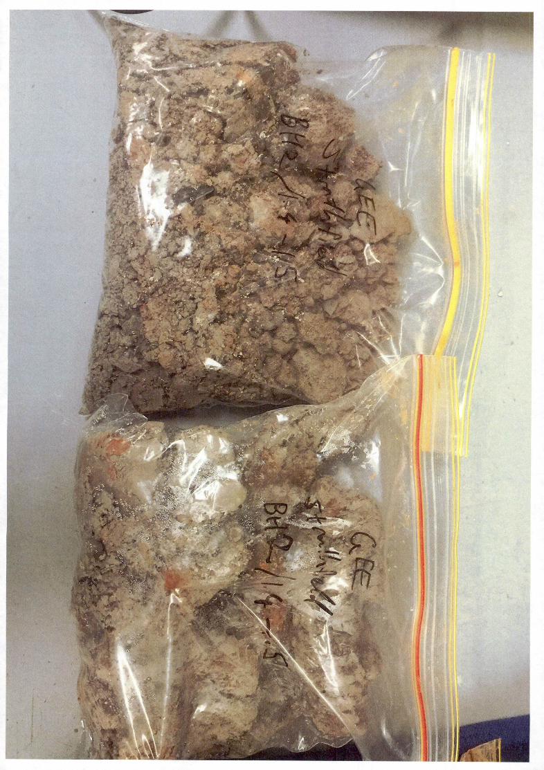
TRANSCRIPT
Mahesh Katragadda
49 Mryna Road
Strathfield NSW 2135
Email: [email protected]
14th April 2017
RE: GEOTECHNICAL INVESTIGATION REPORT
49 MYRNA ROAD, STRATHFIELD NSW
Report ID: G17039STR-R01F
Dear Sir/Madam,
Please find below a report on the geotechnical investigation carried out at 49 Myrna Road,
Strathfield, New South Wales (herein referred to as the ‘site’).
1 PROJECT INFORMATION
1.1 INTRODUCTION AND OBJECTIVE
Geo-Environmental Engineering Pty Ltd (GEE) was commissioned by Mahesh Katragadda
to complete a geotechnical investigation of the site in relation to the proposed
construction of a two level house with a single level basement.
GEE understands that the investigation was required to support a development
application with Strathfield Council and to assist with the structural design of the
development.
The report presents the factual results of the field investigations and provides
interpretation and recommendations regarding the ground conditions at the site in
accordance with client requirements and the agreed scope of work.
Geotechnical Investigation Report
49 Myrna Road, Strathfield NSW
G17039STR-R01F Page 2 of 20
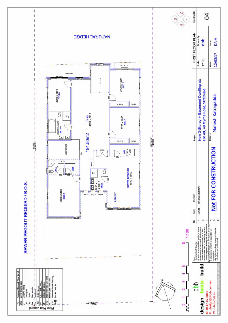
1.2 PROPOSED DEVELOPMENT
Plans of the proposed development are provided for reference in Appendix A and as
previously mentioned it comprises new two level dwelling over a single level basement,
with an in-ground swimming pool at the rear. The basement will be beneath the central
part of the new dwelling and extend to within 1.5m of the northern and southern
boundaries, and over 10m to the eastern and western boundaries. The finished floor
level of the basement has not yet been finalised however, GEE estimates that excavation
of between 3.0 – 3.5m will be required.
The depth of the pool is also not known, however, GEE anticipates that excavation of
between 1.0m and 2.0m will be required. The pool excavation will be approximately
5.0m from the northern and southern boundaries and over 8.0m from the eastern and
western boundaries. Of particular significance to the pool excavation is an existing
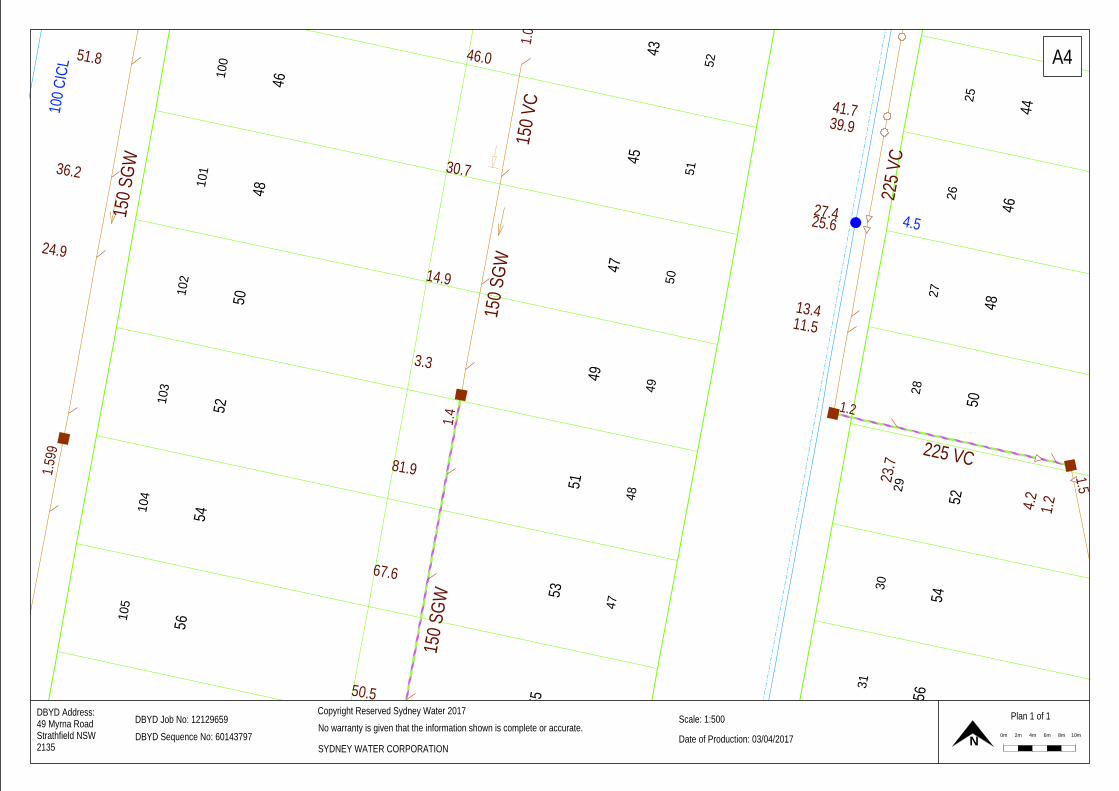
Sydney Water sewer pipeline which passes within close proximity to the western end of
the pool. According to the Sydney Water Dial-Before-You-Dig (DBYD) plan (Appendix
B), the sewer comprises a 150mm diameter salt glazed ware pipe and it has an invert
depth of approximately 1.4m. This sewer will require protection prior and during
excavation works and consideration will need to be given to technical guidelines relating
to building over, or adjacent, to pipe assets (reference 1).
1.3 SCOPE OF WORK
The scope of work undertaken by GEE, to satisfy the above objective, was as follows:
Visual appraisal of the site conditions and locality,
Review of published geological maps for the area,
The drilling of boreholes and the performance of a Dynamic Cone Penetrometer
(DCP) tests to assess the ground conditions,
Collection of representative soil samples for the preliminary assessment of soil
salinity and aggressivity, and
Engineering assessment and reporting.

Geotechnical Investigation Report
49 Myrna Road, Strathfield NSW
G17039STR-R01F Page 3 of 20
2 SITE INFORMATION
2.1 SITE DESCRIPTION
The site is located on the western side of Myrna Road and is legally described as Lot 49
in Deposited Plan 14613. The site covers an area of 626.8m2 (by title) and is currently
occupied by a single-storey brick cottage located in the central portion of the site. A
detached garage at the north-western end is connected to Myrna road by a driveway
that extends eastwards along the northern border. The remainder of the site is occupied
by grass lawns, some paved areas, garden beds and small trees.
As previously mentioned, there exists a Sydney Water sewer pipeline which crosses the
rear (western part) of the site and services the properties to the north (43, 45 and 47
Myrna Road). According to the Sydney Water Dial-Before-You-Dig (DBYD) plan
(Appendix B), the sewer comprises a 150mm diameter salt glazed ware pipe and it has
an invert depth of approximately 1.4m.
2.2 TOPOGRAPHY
The site is located on a gentle slope, with highest ground at the north-eastern corner
sloping away at an average grade of approximately 5% to the south-west. According to
the development plans (Appendix A), the site elevation falls from approximately 25.53m
at the north-eastern corner to 23.21m, (AHD) at the south western corner.
2.3 REGIONAL GEOLOGY AND SOILS
A review of the Sydney 1:100 000 Geological Series Sheet (reference 2) indicates that
the site is underlain by the Bringelly Shale formation of the Wianamatta Group which
typically comprises “...shale, carbonaceous claystone, laminite, fine to medium-grained
lithic sandstone, rare coal”.
A review of the regional soils map (reference 3) indicates the site is located within the
Blacktown Soil Landscape Group, recognised by gently undulating rises on the underlying
shale formation. Local reliefs are up to 30m and slopes are usually less than 5% in
gradient. Soils of the Blacktown Group typically comprise heavy clays that have been
derived from the weathering process of shale bedrock, have low fertility and are often
strongly acidic.

Geotechnical Investigation Report
49 Myrna Road, Strathfield NSW
G17039STR-R01F Page 4 of 20
2.4 REGIONAL HYDROGEOLOGY
The regional and permanent groundwater in the vicinity of the site, is expected to be
confined or partly confined, discrete, water-bearing zones within the bedrock formation.
However, intermittent ‘perched’ water seepage often occurs at the soil / bedrock interface
following heavy and prolonged rainfall events.
Permanent groundwater associated with the Wianamatta group of Shale bedrock is
characterised by high salinity (reference 4 and 5) and high ammonia concentrations (>10
mg/L, reference 6). In this regard, groundwater within the shale formation is not
extracted for potable use and rarely extracted for commercial / industrial purposes. This
is supported by a review of the NSW Water Information database
(http://waterinfo.nsw.gov.au/gw/) for registered groundwater bores in the vicinity of the
site. The search revealed that there are no bores within 500m of the site.
The rate of groundwater movement is likely to be low as a result of low relief, low altitude
(approximately ~ 25m AHD) and the low permeability of the Shale (between 10-13 and
10-9 m/sec – reference 7). Groundwater flow is dominated by water movement through
fractures (or joints), where stress has caused partial loss of cohesion in the rock and
evidence of potential water bearing fractures is usually the presence of clay or iron-
staining along face of the joints.
2.5 ACID SULFATE SOIL RISK
Acid Sulfate Soil is naturally occurring sediments and soils containing iron sulfides
(principally iron sulfide, iron disulfide or their precursors). Oxidation of these soils through
exposure to the atmosphere or through lowering of groundwater levels results in the
generation of sulfuric acid.
Land that may contain potential acid sulfate soils was mapped by the NSW Department
of Land and Water Conservation (DLWC) and based on these maps local Councils
produced their own acid sulfate soil maps to be used for planning purposes.
The DLWC ‘Botany Bay’ Acid Sulfate Soil Risk Map (reference 8), indicates that the site
lies within an area with no known occurrences of acid sulphate soil and land activities
within this area are “...not likely to be affected by acid sulphate soil materials”.
The Acid Sulfate Soils Map produced by Council (reference 9) indicates that the site lies
within an area defined as “Class 5”. In accordance with Clause 6.1 of Strathfield City
Council’s LEP (reference 10), a preliminary assessment of acid sulphate soil and

Geotechnical Investigation Report
49 Myrna Road, Strathfield NSW
G17039STR-R01F Page 5 of 20
potentially a management plan, is required for “…works within 500m of adjacent Class
1, 2, 3 or 4 land that is below 5 metres Australian Height Datum and by which the
watertable is likely to be lowered below 1 metre Australian Height Datum on adjacent
Class 1, 2, 3 or 4 land”.
Firstly, the surface elevation is much greater than 5m AHD (at approximately 25m AHD).
Secondly, the maximum depth of proposed excavation is expected to be 3.5m below the
ground surface (bgs) which equates to a bulk excavation level which is significantly
greater than 1m AHD. In this regard, there is no need for an acid sulphate soil
assessment or management plan.

Geotechnical Investigation Report
49 Myrna Road, Strathfield NSW
G17039STR-R01F Page 6 of 20
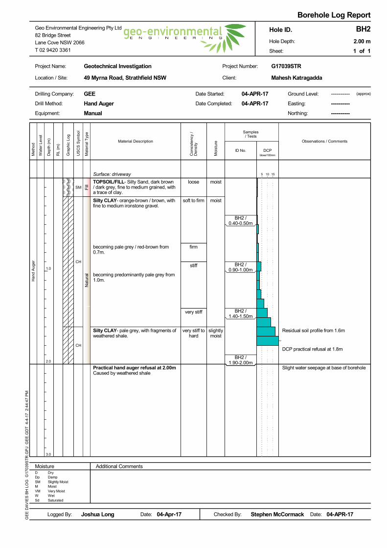
3 METHOD OF INVESTIGATION
Fieldwork was completed on the 4th April 2017 by Joshua Long, a geotechnical engineer
and comprised:
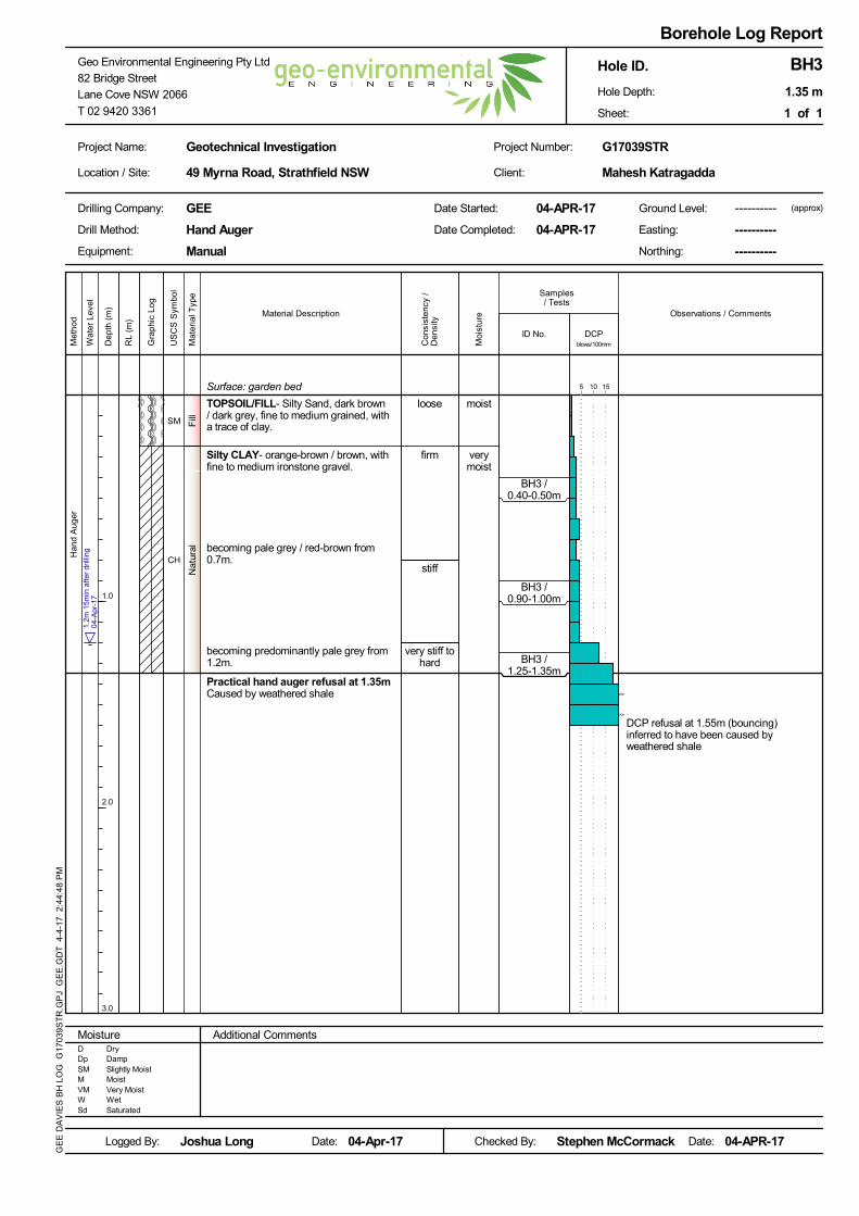
The drilling and logging of three boreholes (BH1 to BH3) in accessible areas of the
site to assess the soil conditions and depth to bedrock,
The performance of DCP tests adjacent to each borehole to assess the consistency
and/or relative density of the soil profile and to assist with determining the depth
to bedrock, and
The collection of representative soil samples for the preliminary assessment of soil
salinity and aggressivity.
The boreholes were drilled using an 85mm diameter stainless steel hand auger, while
the DCP tests were performed in accordance with Australian Standard Test Method
AS1289.6.3.2-1997 (reference 11). Each borehole was advanced through topsoil / fill
material and the natural soil profile before refusing on weathered shale bedrock at depths
of 2.0m below ground surface (bgs) at BH1, 2.0 m bgs at BH2 and 1.35m bgs at BH3.
The DCP tests were terminated due to practical refusal at a similar depth to the boreholes
which support the conclusion that bedrock had been encountered. The exception to this
was borehole BH3 where the DCP extended to a slightly greater depth of 1.55m before
refusing on weathered shale bedrock.
The location of the boreholes and DCP tests were estimated using measurements from
existing features and is shown on Figure 1. A copy of the borehole logs, including DCP
test results, is provided in Appendix C.
Geotechnical Investigation Report
49 Myrna Road, Strathfield NSW
G17039STR-R01F Page 7 of 20
4 INVESTIGATION RESULTS
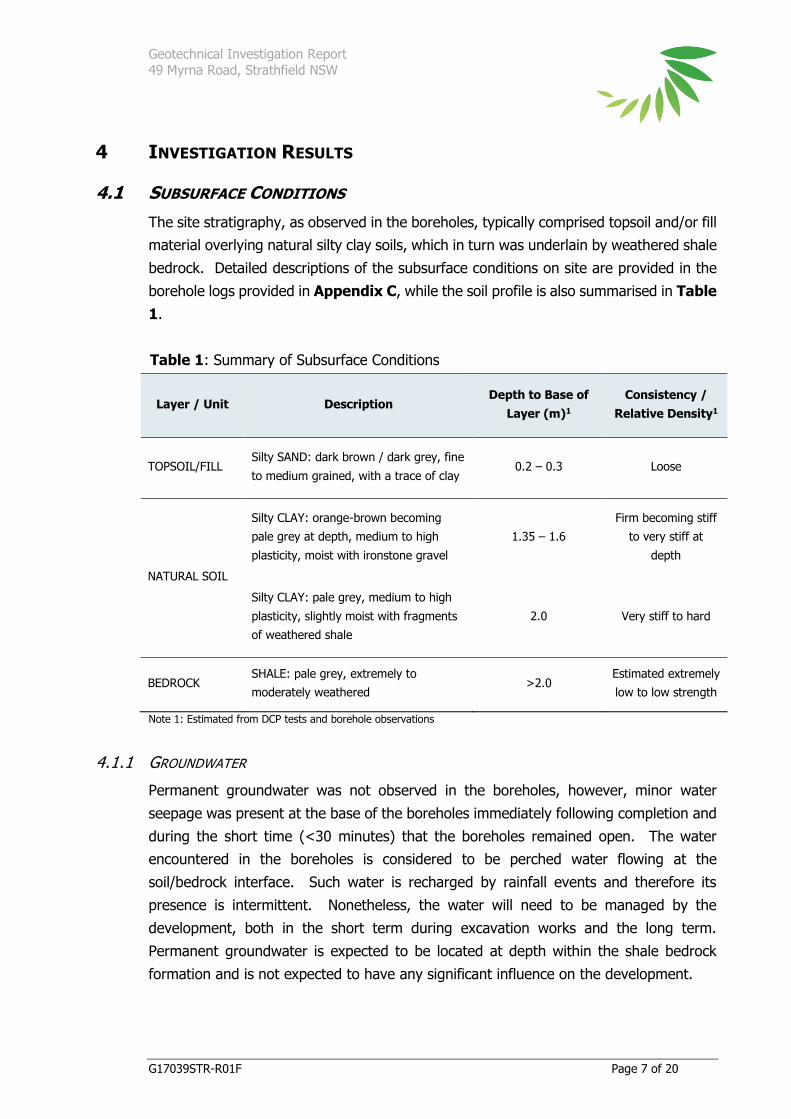
4.1 SUBSURFACE CONDITIONS
The site stratigraphy, as observed in the boreholes, typically comprised topsoil and/or fill
material overlying natural silty clay soils, which in turn was underlain by weathered shale
bedrock. Detailed descriptions of the subsurface conditions on site are provided in the
borehole logs provided in Appendix C, while the soil profile is also summarised in Table
1.
Table 1: Summary of Subsurface Conditions
Layer / Unit Description Depth to Base of
Layer (m)1
Consistency /
Relative Density1
TOPSOIL/FILL Silty SAND: dark brown / dark grey, fine
to medium grained, with a trace of clay 0.2 – 0.3 Loose
NATURAL SOIL
Silty CLAY: orange-brown becoming
pale grey at depth, medium to high
plasticity, moist with ironstone gravel
1.35 – 1.6
Firm becoming stiff
to very stiff at
depth
Silty CLAY: pale grey, medium to high
plasticity, slightly moist with fragments
of weathered shale
2.0 Very stiff to hard
BEDROCK SHALE: pale grey, extremely to
moderately weathered >2.0
Estimated extremely
low to low strength
Note 1: Estimated from DCP tests and borehole observations
4.1.1 GROUNDWATER
Permanent groundwater was not observed in the boreholes, however, minor water
seepage was present at the base of the boreholes immediately following completion and
during the short time (<30 minutes) that the boreholes remained open. The water
encountered in the boreholes is considered to be perched water flowing at the
soil/bedrock interface. Such water is recharged by rainfall events and therefore its
presence is intermittent. Nonetheless, the water will need to be managed by the
development, both in the short term during excavation works and the long term.
Permanent groundwater is expected to be located at depth within the shale bedrock
formation and is not expected to have any significant influence on the development.

Geotechnical Investigation Report
49 Myrna Road, Strathfield NSW
G17039STR-R01F Page 8 of 20
4.2 LABORATORY TESTING
Samples of soil were collected from each borehole and submitted to Envirolab Services
Pty Ltd (Envirolab) and for selective testing which included:
Electrical Conductivity (EC) to provide a detailed assessment of the salinity potential
of the soil profile, and
Sulphate, Chloride, resistivity and pH to determine the exposure classification of
the soil with respect to buried structural concrete and unprotected steel.
The laboratory test results are presented in Appendix D, while a summary of the results
is provided in the following sub-sections.
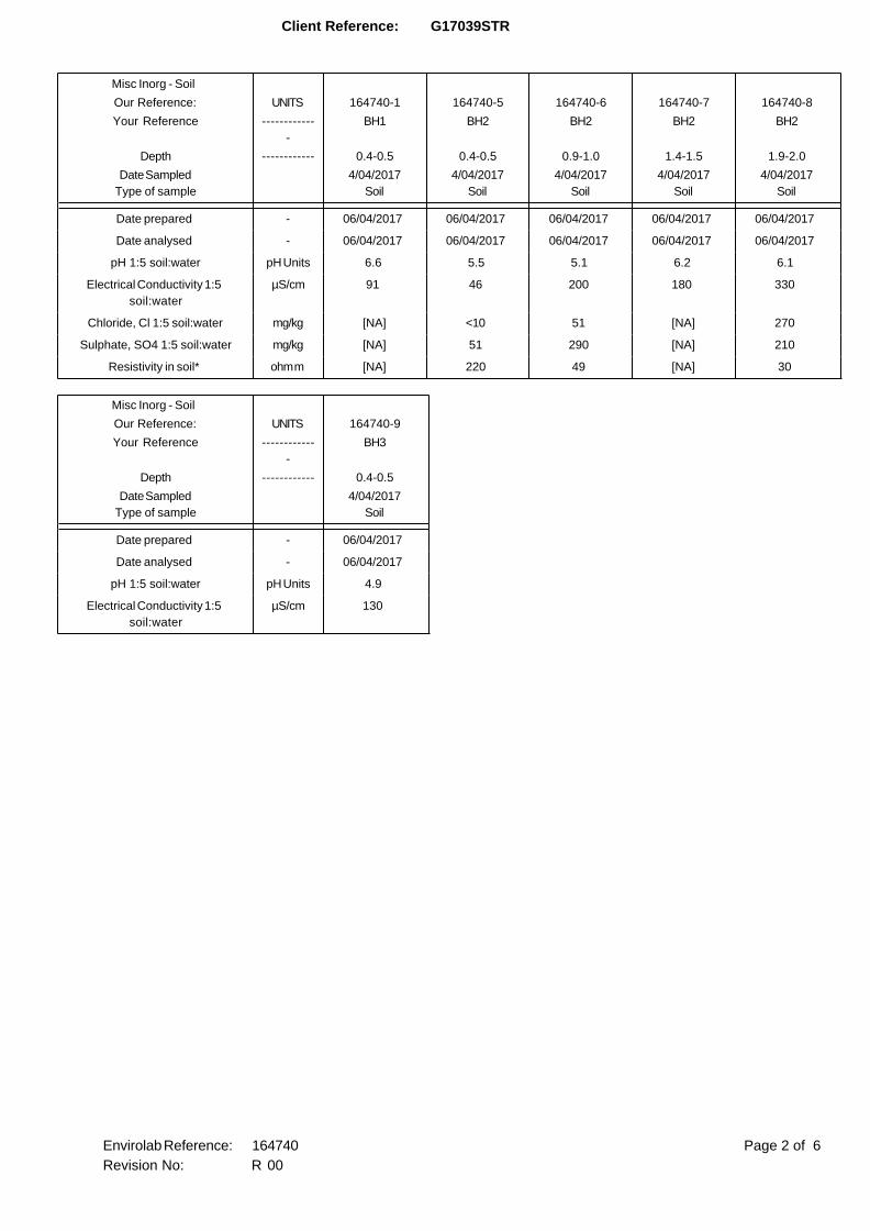
4.2.1 SOIL SALINITY TESTING
An assessment of soil salinity conditions has been undertaken with reference to guidance
published by the Department Land and Water Conservation NSW (reference 12). In this
regard, selected samples of natural soil and bedrock were submitted to Envirolab for
NATA accredited testing of electrical conductivity (EC), which is the primary indicator of
salinity.
The raw EC results and the ECe results1, are provided in Table 2 and reveal that the soil
profile was typically non-saline.
Table 2: Electrical Conductivity Results
Location / Depth
(m bgs)
Sample
Description
EC
(dS/m)
Multiplication
Factor1
ECe
(dS/m)
BH1 / 0.4 – 0.5 Silty CLAY 0.091 6 0.546
BH2 / 0.4 – 0.5 Silty CLAY 0.046 6 0.276
BH2 / 0.9 – 1.0 Silty CLAY 0.200 6 1.200
BH2 / 1.4 – 1.5 Silty CLAY 0.180 6 1.080
BH2 / 1.9 – 2.0 Silty CLAY 0.330 6 1.980
BH3 / 0.4 – 0.5 Silty CLAY 0.130 6 0.780
4.2.2 AGGRESSIVITY TESTING
Selected soil samples (comprising natural clay soil) were submitted to Envirolab for NATA
accredited testing of pH, sulfate, chloride and resistivity to provide a preliminary
1 ECe results are EC data multiplied by a conversion factor which depends upon the soil texture / type
(reference 12)

Geotechnical Investigation Report
49 Myrna Road, Strathfield NSW
G17039STR-R01F Page 9 of 20
assessment of the exposure classification (or aggressiveness/corrosiveness potential) of
the soil with respect to future buried steel and/or concrete (e.g. footings).
To determine the aggressiveness of the soil and water environment on concrete or steel,
the chemical test results are compared to Tables 6.4.2(C) and 6.5.2(C) from Section 6 of
the Australian Standard AS 2159 (reference 13). This section provides assessment criteria
to assess the ‘exposure classification’ for a concrete or steel pile. The Standard has two
classes of soil conditions:
(A) high permeability soils below groundwater; and
(B) low permeability soils and all soils above groundwater.
For this site, all the soil samples are considered to be condition ‘B’. Based on the chemical
testing results, the standard provides a range of ‘exposure classifications’ from non-
aggressive to very severe. For the range of chemical conditions in the soil surrounding
the structure, the condition leading to the most severe aggressive conditions is adopted.
A summary of the soil results is provided in Table 3.
Table 3: Exposure classification (aggressivity) test results
Sample ID Location / Depth
(m bgs)
Soil
Condition pH
Sulphate
(SO4)
mg/kg
Chloride
(Cl)
mg/kg
Resistivity
Ohm.cm
BH1 / 0.4 – 0.5 BH1 / 0.4 – 0.5 B 6.6 -- -- --
BH2 / 0.4 – 0.5 BH2 / 0.4 – 0.5 B 5.5 51 <10 22,000
BH2 / 0.9 – 1.0 BH2 / 0.9 – 1.0 B 5.1 290 51 4,900
BH2 / 1.4 – 1.5 BH2 / 1.4 – 1.5 B 6.2 -- -- --
BH2 / 1.9 – 2.0 BH2 / 1.9 – 2.0 B 6.1 210 270 3,000
BH3 / 0.4 – 0.5 BH3 / 0.4 – 0.5 B 4.9 -- -- --
The aggressivity potential of an environment on concrete is dependent on the sulphate
and pH levels of the soil. Based on the limited number of test results above and taking
into account the ‘worst-case’ sample, the subsurface profile is mildly-aggressive towards
concrete. According to Australian Standard AS 3600-2009 (reference 14), specifically
Table 4.8.1, this equates to an exposure classification of ‘A2’. The corrosive potential of
an environment on unprotected steel is typically dependent on pH, chloride, and
resistivity levels of the soil. Based on the limited number of test results above and taking
into account the ‘worst-case’ sample, the subsurface profile is considered to be non-
aggressive / non-corrosive towards any unprotected steel.

Geotechnical Investigation Report
49 Myrna Road, Strathfield NSW
G17039STR-R01F Page 10 of 20
5 DISCUSSION
5.1 SITE PREPARATION
Following demolition of the existing structures and prior to bulk excavation works, all
topsoil with organic matter and any pavement materials, should be removed from the
proposed building and pavement areas. Stripped topsoil should be stockpiled for re-use
as landscape material, or disposed off-site.
Material removed from site will need to be managed in accordance with the provisions
of current legislation and may include segregation by material type classification in
accordance with NSW EPA (2014) Waste Classification Guidelines (reference 15) and
disposal at facilities appropriately licensed to receive the particular materials. GEE notes
that the natural soil and bedrock may be classified as Virgin Excavated Natural Material
(VENM) and re-used on other sites rather than disposed at a landfill, although it must be
proven to be free of contamination.
GEE notes that the natural silty clay soil profile is expected to be susceptible to loss of
strength when wet. In this regard, it may be necessary to construct a working platform
above the prepared sub-grade in areas of high construction vehicle traffic, comprising a
minimum of 150 mm of gravel or recycled concrete.
5.2 EARTHWORKS
Based on the development plans provided in Appendix A, earthworks at the site will
comprise excavation to a depth of between approximately 3.0 to 3.5m to facilitate the
construction of the proposed basement, and between 1.0m and 2.0m depth to construct
the pool. The excavation for the basement is expected to extend to within 1.5m of the
northern and southern boundaries, and over 10m to the eastern and western boundaries.
Of particular significance for the pool excavation is a Sydney Water sewer pipeline that
passes within close proximity to the southern end of the proposed pool. In this regard
discussions with Sydney Water are recommended with approval needed for any
realignment work.
5.2.1 EXCAVATION
Based on the fieldwork undertaken as part of this investigation, the excavation will
encounter minor surface fill and topsoil material across the site, overlying firm to stiff
clay becoming very stiff with depth before encountering weathered shale bedrock at a
depths of between approximately 1.6m and 2.0m. GEE notes that the strength of the
shale bedrock has not been assessed as part of this geotechnical investigation, however,

Geotechnical Investigation Report
49 Myrna Road, Strathfield NSW
G17039STR-R01F Page 11 of 20
based on local knowledge it is likely to be initially extremely low to low strength,
becoming at least low to medium strength with depth. To confirm the strength of the
bedrock within the depth of proposed excavation would require more detailed
investigations (preferably following demolition of the existing dwelling) including the
coring and strength testing of the bedrock formation.
The majority of the excavation, through the fill/soil profile and into very low to low
strength rock, is expected to be readily excavated using standard equipment such as
excavators, although the use of an impact hammer may be required if medium strength
or better rock, combined with unfavourable rock-defect geometry, is encountered.
Should an impact hammer be required then the effects of vibration should be considered
and are discussed further in Section 5.2.3.
5.2.2 GROUNDWATER INFLOW
Permanent groundwater was not encountered during the drilling of the boreholes
however some minor seepage was observed near the soil/brock interface during the short
time that the boreholes remained open. In general, seepage can be expected to occur
over time at the soil / bedrock interface, ironstone gravel bands and through natural
joints and fractures within the underlying bedrock formation. Such seepage should be
manageable during the earthworks phase by pumping from a sump at the base of the
excavation. In the long term conventional techniques such as strip drains behind the
basement walls and ag-lines will need to be incorporated into the design of the basement.
5.2.3 CONSTRUCTION / EXCAVATION INDUCED VIBRATION
When using a hydraulic hammer, vibrations will be transmitted through the ground and
potentially impact on adjoining structures. Where possible, the use of other techniques
not involving impact (e.g. rock saws), should be adopted as they would reduce or possibly
eliminate risks of damage due to vibrations.
The structures on the adjacent properties are sensitive to vibrations above certain
threshold levels (regarding potential for cracking). Given that the proposed basement
excavation will extend to within close proximity of the boundaries and adjoining
development, close controls by the excavation contractor over the rock excavation are
necessary, and are recommended, so that excessive vibration effects are not generated.
Peak Particle Velocity (PPV) is usually the adopted measure of ground vibration and the
safe limits depend on the sensitivity of the adjoining structures and services. There is a
number of Australian and overseas publications which provide vibration velocity guideline
levels (or safe limits) including:
Geotechnical Investigation Report
49 Myrna Road, Strathfield NSW
G17039STR-R01F Page 12 of 20
Australian Standard AS2187.2-2006 Explosives - Storage and use - Use of explosives
- Appendix J: Ground Vibrations and Airblast Overpressure (reference 16).
Australian Standard AS41670.2-1990 Evaluation of human exposure to whole-body
vibration - Part 2: Continuous and shock-induced vibration in buildings (1 to 80 Hz)
(reference 17).
DIN 4150 – Part 3 – 1999. Effects if Vibration on Structures (reference 18).
Department of Environment and Conservation NSW, 2006. Assessing Vibration: a
technical guideline (reference 19).
British Standard BS 7385-1:1990. Evaluation and measurement for vibration in
buildings. Guide for measurement of vibrations and evaluation of their effects on
buildings (reference 20).
British Standard BS 7385-2:1993. Evaluation and measurement for vibration in
buildings. Guide to damage levels from groundborne vibration (reference 21).
The most appropriate guidelines levels for the proposed excavation work are provided in
AS2187.2-2006, which refers to guideline values from BS7385-2 for the prevention of
minor or cosmetic damage occurring in structures from ground vibration. Additionally,
the guideline levels provided in DIN 4150 Part 3 is considered an appropriate source for
guideline levels.
Ideally, safe limits should be determined by a specialist vibration consultant, with
consultation with Sydney Water also recommended. However, as a preliminary and
conservative guide, and considering the above guidelines and the type of nearby
structures (including Sydney Water assets), GEE recommend that excavation methods
should be adopted which limit ground vibrations at the adjoining developments to not
more than 5mm/sec, and vibration monitoring will be required to verify that this is
achieved.
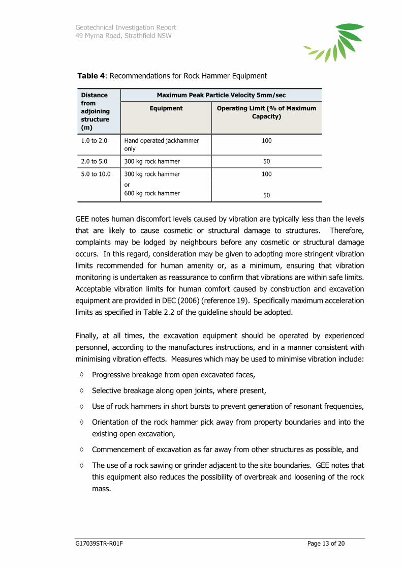
As a guide, the PPV limits of 5mm/sec are expected to be achievable if rock breaker
equipment or other excavation methods are restricted as indicated in Table 4.
Geotechnical Investigation Report
49 Myrna Road, Strathfield NSW
G17039STR-R01F Page 13 of 20
Table 4: Recommendations for Rock Hammer Equipment
Distance
from
adjoining
structure
(m)
Maximum Peak Particle Velocity 5mm/sec
Equipment Operating Limit (% of Maximum
Capacity)
1.0 to 2.0 Hand operated jackhammer
only
100
2.0 to 5.0 300 kg rock hammer 50
5.0 to 10.0 300 kg rock hammer 100
or
600 kg rock hammer 50
GEE notes human discomfort levels caused by vibration are typically less than the levels
that are likely to cause cosmetic or structural damage to structures. Therefore,
complaints may be lodged by neighbours before any cosmetic or structural damage
occurs. In this regard, consideration may be given to adopting more stringent vibration
limits recommended for human amenity or, as a minimum, ensuring that vibration
monitoring is undertaken as reassurance to confirm that vibrations are within safe limits.
Acceptable vibration limits for human comfort caused by construction and excavation
equipment are provided in DEC (2006) (reference 19). Specifically maximum acceleration
limits as specified in Table 2.2 of the guideline should be adopted.
Finally, at all times, the excavation equipment should be operated by experienced
personnel, according to the manufactures instructions, and in a manner consistent with
minimising vibration effects. Measures which may be used to minimise vibration include:
Progressive breakage from open excavated faces,
Selective breakage along open joints, where present,
Use of rock hammers in short bursts to prevent generation of resonant frequencies,
Orientation of the rock hammer pick away from property boundaries and into the
existing open excavation,
Commencement of excavation as far away from other structures as possible, and
The use of a rock sawing or grinder adjacent to the site boundaries. GEE notes that
this equipment also reduces the possibility of overbreak and loosening of the rock
mass.

Geotechnical Investigation Report
49 Myrna Road, Strathfield NSW
G17039STR-R01F Page 14 of 20
5.2.4 EXCAVATION SUPPORT
The topsoil / fill layer, natural soil and the upper portion of the shale formation (typically
extremely low to very low strength shale) may be temporarily battered to no steeper
than 1.5 Horizontal to 1 Vertical. This batter slope assumes that the ground surface
beyond the crest is horizontal and there are no surcharge loads within a distance of the
crest equal to the vertical height of the cut.
Where this batter slope cannot be safely adopted, either temporary shoring or the early
construction of permanent walls designed to shore up the soil profile and adjoining
structures/services, will be required. Options for shoring include the use of evenly spaced
bored piles and should be designed by a suitably experienced structural engineer in
accordance with AS 4678-2002 Earth Retaining Structures (reference 22) and consider
both the short and long term configurations. Should the shoring walls be cantilevered
or supported by a single row of anchors and some wall movements can be tolerated
(flexible wall), the pressure acting on the wall can be estimated on the basis of a
triangular earth pressure distribution.
When internal props, such as the ground floor slab, restrain retaining wall movement, or
where significant movements cannot be tolerated (rigid wall), an ‘at-rest’ earth pressure
coefficient (Ko) should be adopted with either a uniform or trapezoidal pressure
distribution. It should be noted that shoring which is designed for this ‘at rest’ coefficient
may still undergo some lateral movements, depending on the final configuration of the
wall and construction sequence.
The design of any retaining structures should make allowance for all applicable surcharge
loadings including construction activities around the perimeter of the excavation and
adjacent buildings. Consideration should be given to the possibility of a hydrostatic
pressure due to build-up of water behind the wall (e.g. from broken services), unless
permanent subsurface drainage can be provided.
Finally, computer aided analysis may be carried out to assess potential ground
movements based on different wall designs and construction sequence, so as to control
deflections to within tolerable limits. It is also considered prudent to carry out surveys
before and after installation to measure the actual movement of the wall or soil.
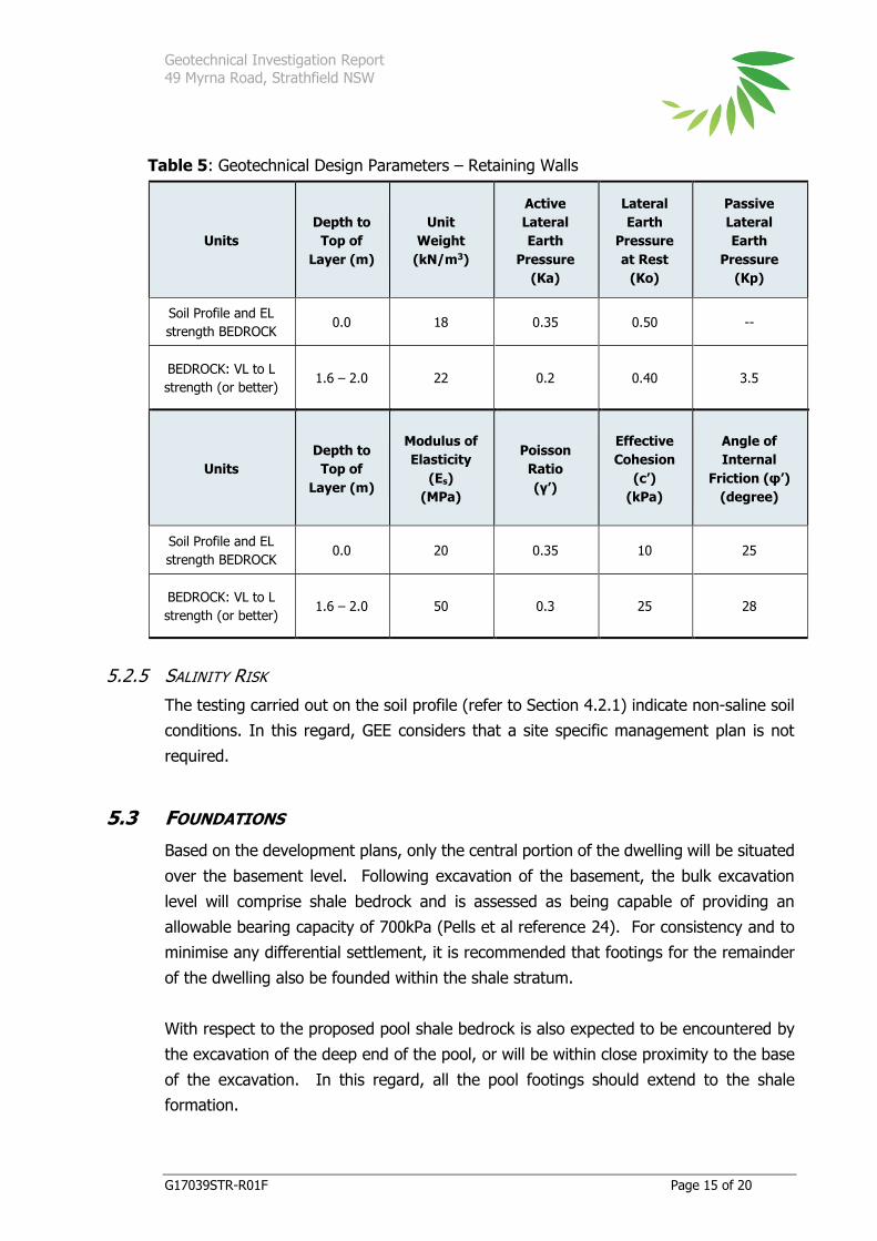
Geotechnical parameters for the soil and bedrock profile encountered at the site are
provided in Table 5.
Geotechnical Investigation Report
49 Myrna Road, Strathfield NSW
G17039STR-R01F Page 15 of 20
Table 5: Geotechnical Design Parameters – Retaining Walls
Units
Depth to
Top of
Layer (m)
Unit
Weight
(kN/m3)
Active
Lateral
Earth
Pressure
(Ka)
Lateral
Earth
Pressure
at Rest
(Ko)
Passive
Lateral
Earth
Pressure
(Kp)
Soil Profile and EL
strength BEDROCK 0.0 18 0.35 0.50 --
BEDROCK: VL to L
strength (or better) 1.6 – 2.0 22 0.2 0.40 3.5
Units
Depth to
Top of
Layer (m)
Modulus of
Elasticity
(Es)
(MPa)
Poisson
Ratio
(γ’)
Effective
Cohesion
(c’)
(kPa)
Angle of
Internal
Friction (φ’)
(degree)
Soil Profile and EL
strength BEDROCK 0.0 20 0.35 10 25
BEDROCK: VL to L
strength (or better) 1.6 – 2.0 50 0.3 25 28
5.2.5 SALINITY RISK
The testing carried out on the soil profile (refer to Section 4.2.1) indicate non-saline soil
conditions. In this regard, GEE considers that a site specific management plan is not
required.
5.3 FOUNDATIONS
Based on the development plans, only the central portion of the dwelling will be situated
over the basement level. Following excavation of the basement, the bulk excavation
level will comprise shale bedrock and is assessed as being capable of providing an
allowable bearing capacity of 700kPa (Pells et al reference 24). For consistency and to
minimise any differential settlement, it is recommended that footings for the remainder
of the dwelling also be founded within the shale stratum.
With respect to the proposed pool shale bedrock is also expected to be encountered by
the excavation of the deep end of the pool, or will be within close proximity to the base
of the excavation. In this regard, all the pool footings should extend to the shale
formation.

Geotechnical Investigation Report
49 Myrna Road, Strathfield NSW
G17039STR-R01F Page 16 of 20
By founding the pool and the dwelling within the shale formation, GEE expects that the
requirements of Sydney Water will also be met (reference 1). Sydney Water requires
that when building over, adjacent to, or under Sydney Water pipe assets, the work must
not obstruct full and free access to the assets, cause physical damage to the assets, or
weaken the assets leading to future damage. By protecting the Sydney Water asset from
additional loads, and potential damage, the proposed development is also protected at
some future time, should repairs to the asset be required.
In this regard, it is important that foundations for the new development be extended
below the ‘Zone of Influence’ (ZOI) of the adjacent sewer pipeline. The ZOI is defined
by Sydney Water as a “…notional envelope within which an external vertical load would
exert stress on the pipe (Figure 1). The zone is defined by the lines from the bottom
projection of the pipe extending upwards at an angle of 45° to the ground surface”.
Finally, footing systems should be designed by a suitably qualified and experienced
structural engineer and GEE recommends that inspection by a geotechnical engineer is
undertaken during the piering stage to confirm that the design founding conditions have
been achieved.
5.3.1 AGGRESSIVITY / EXPOSURE CLASSIFICATION
Based on the limited exposure classification test results (Section 4.2.2), and in
accordance with AS 2159-2009 (reference 13), the subsurface concrete structures (e.g.
footings) should be designed based on mildly-aggressive soil conditions for concrete.
According to Australian Standard AS 3600-2009 (reference 14), the equivalent exposure
classification is ‘A2’. With respect to unprotected steel, the silty clay soil profile is
considered to be non-corrosive.

Geotechnical Investigation Report
49 Myrna Road, Strathfield NSW
G17039STR-R01F Page 17 of 20
6 CONCLUSION
GEE considers that sufficient information has been gained to be confident of the
subsurface conditions across the site, to assist with design and construction of the
proposed development at 49 Myrna Road, Strathfield.
Based on the results of the preliminary investigation, the proposed development is
considered feasible. Additionally, GEE concludes that the existing rock formation is
capable of withstanding the proposed loads to be imposed, and standard shoring works
(provided they are designed by a structural engineer), will ensure the stability of the
excavation and provide protection and support of adjoining properties.
The geotechnical issues associated with the proposed development have been addressed
by the investigation and are discussed in this report. If, during construction, any
conditions are encountered that vary significantly from those described or inferred in the
above report, it is a condition of the report that we be advised so that those conditions,
and the conclusions discussed in the report, can be reviewed and alternative
recommendations assessed, if appropriate.
GEE will be pleased to assist with any further advice or geotechnical services required in
regard to the proposed development.

Geotechnical Investigation Report
49 Myrna Road, Strathfield NSW
G17039STR-R01F Page 18 of 20
7 GENERAL LIMITATIONS
Soil and rock formations are variable. The logs or other information presented as part
of this report indicate the approximate subsurface conditions only at the specific test
locations. Boundaries between zones on the logs or stratigraphic sections are often not
distinct, but rather are transitional and have been interpreted.
The precision with which subsurface conditions are indicated depends largely on the
frequency and method of sampling, and on the uniformity of subsurface conditions. The
spacing of test sites also usually reflects budget and schedule constraints. Groundwater
conditions described in this report refer only to those observed at the place and under
circumstances noted in the report. The conditions may vary seasonally or as a
consequence of construction activities on the site or adjacent sites.
Where ground conditions encountered at the site differ significantly from those
anticipated in the report, either due to natural variability of subsurface conditions or
construction activities, it is a condition of this report that GEE be notified of any variations
and be provided with an opportunity to review the recommendations of this report.
Recognition of changed soil and rock conditions requires experience and it is
recommended that a suitably experienced geotechnical engineer be engaged to visit the
site with sufficient frequency to detect if conditions have changed significantly.
The comments given in this report are intended only for the guidance of the design
engineer, or for other purposes specifically noted in the report. The number of boreholes
or test excavations necessary to determine all relevant underground conditions which
may affect construction costs, techniques and equipment choice, scheduling, and
sequence of operations would normally be greater than has been carried out for design
purposes. Contractors should therefore rely on their own additional investigations, as
well as their own interpretations of the borehole data in this report, as to how subsurface
conditions may affect their work.

Geotechnical Investigation Report
49 Myrna Road, Strathfield NSW
G17039STR-R01F Page 19 of 20
If you have any questions about the content of this letter, please do not hesitate to contact the
undersigned.
Yours sincerely
Stephen McCormack
Principal
REFERENCES
1. Sydney Water, 2015. Technical guidelines – Building over and adjacent to pipe assets.
October 2015
2. Department of Mineral Resources, 1983: Sydney 1:100,000 Geological Series Map Sheet
9130 (Edition 1).
3. Department of Land and Water Conservation (DLWC), 2004: Sydney 1:100 000 Soil
Landscape Series Sheet 9130 (second edition).
4. Wooley, D.R., 1983: Groundwater. In Herbert, C., (Ed), Geology of the Sydney 1:100,000
Sheet 9130, Geological Survey of New South Wales, Department of Mineral Resources,
pp. 145-148.
5. Krumins, H., Bradd, J., and McKibbon, D., 1998: Hawkesbury-Nepean Catchment
Groundwater Availability Map: Map Notes. Department of Land and Water Conversation,
December, 1998, Parramatta, 12 pp.
6. Old, A. N., 1942: The Wianamatta Shale Waters of the Sydney District. Agricultural
Gazette of New South Wales, Miscellaneous Publication 3225.
7. Cook P.G., 2003: A Guide to Regional Groundwater Flow in Fractured Rock Aquifers.
Seaview Press, Henley Beach (South Australia), 108pp.
8. DLWC, 1997: Department of Land and Water Conservation of NSW, 1997: Botany Bay
Acid Sulfate Soil Risk Map – Edition Two.
9. Strathfield Council, 2012: Strathfield Local Environmental Plan 2012 Acid Sulfate Soils Map
– Sheet ASS_002.
10. Strathfield City Council, 2012. Strathfield Local Environmental Plan 2012
11. Australian Standards, 1997. AS1289.6.3.2 Determination of the penetration resistance of
a soil – 9kg dynamic cone penetrometer test.
12. Department of Land and Water Conservation NSW, 2002: Site investigations for
urban salinity.

Geotechnical Investigation Report
49 Myrna Road, Strathfield NSW
G17039STR-R01F Page 20 of 20
13. Australian Standard (AS) 2159 -2009: Piling Design and Installation.
14. Australian Standard (AS) 3600 –2009: Concrete Structures.
15. New South Wales Environment Protection Authority (NSW EPA), 2014: Waste
classification guidelines – Part 1 classifying waste. November 2014
16. Australian Standard AS2187.2-2006 Explosives - Storage and use - Use of explosives -
Appendix J: Ground Vibrations and Airblast Overpressure.
17. Australian Standard AS2670.2-1990: Evaluation of human exposure to whole-body
vibration - Part 2: Continuous and shock-induced vibration in buildings (1 to 80 Hz).
18. DIN 4150 – Part 3 – 1999. Effects if Vibration on Structures.
19. Department of Environment and Conservation NSW, 2006. Assessing Vibration: a
technical guideline.
20. British Standard BS 7385-1:1990. Evaluation and measurement for vibration in buildings.
Guide for measurement of vibrations and evaluation of their effects on buildings.
21. British Standard BS 7385-2:1993. Evaluation and measurement for vibration in buildings.
Guide to damage levels from groundborne vibration.
22. Australian Standard AS4678-2002: Australian Standard, 2002: Earth Retaining Structures.
23. Australian Standard: AS3798-2007: Guidelines on earthworks for commercial and
residential developments.
24. Pells et al, 1998: Foundations on Sandstone and Shale in the Sydney Region, Australian
Geomechanics Society, 1998.

Geotechnical Investigation Report
49 Myrna Road, Strathfield NSW
G17039STR-R01F
FIGURE 1
SITE PLAN

SITE PLAN49 Myrna Road, Strathfield NSW
Aerial image: provided by SIXmaps (NSW LPI) - retrieved 04/04/2017
A
182 BRIDGE STREETLANE COVE NSW 2066P - 61 (2) 9420 3361E - [email protected]
DRAWN:
DATE:SCALE:
JOB No.: REVISION:
N.T.S
J. Long
TITLE: FIGURE No.:4 April 2017
G17039STR
North
Approximate Site Boundary
BH1
Approximate Footprint of Proposed Basement
Sydn
ey W
ater
Sew
er L
ine
BH2
BH3
Approximate Footprint of Proposed Pool
Approximate Footprint of Proposed development

Geotechnical Investigation Report
49 Myrna Road, Strathfield NSW
G17039STR-R01F
APPENDIX A
Proposed Development Plans (5 Sheets)


Geotechnical Investigation Report
49 Myrna Road, Strathfield NSW
G17039STR-R01F
APPENDIX B
Sydney Water Dial Before You Dig (1 Sheet)
100
101
25
26
52
51
50
49
48
27
28
29
30
31
47
103
104
102
105
4648
44
4345
4749
51
4648
5052
5456
5355
5052
5456
46.0
30.7
51.8
36.2
41.739.9
25.627.4
13.411.5
1.24.2
23.7
24.9
14.9
3.3
81.9
67.6
50.5
1.0
1.2
1.51.
599
1.4
150
VC
150
SGW
225
VC
150
SGW
225 VC15
0 SG
W
4.5
100
CICL
N0m 2m 4m 6m 8m 10m
Plan 1 of 1Copyright Reserved Sydney Water 2017
Date of Production: 03/04/2017
A4
SYDNEY WATER CORPORATION
DBYD Address: 49 Myrna RoadStrathfield NSW2135
DBYD Job No: 12129659
DBYD Sequence No: 60143797No warranty is given that the information shown is complete or accurate.
Scale: 1:500
Geotechnical Investigation Report
49 Myrna Road, Strathfield NSW
G17039STR-R01F
APPENDIX C
Borehole Logs (4 Sheets)

Han
d A
uger
SM
CH
CH
TOPSOIL/FILL- Silty Sand, dark brown/ dark grey, fine to medium grained, witha trace of clay.
Silty CLAY- orange-brown / brown, withfine to medium ironstone gravel.
becoming pale grey / red-brown from0.8m.
becoming predominantly pale grey from1.4m.
Silty CLAY- pale grey, with fragments ofweathered shale.
Practical hand auger refusal at 2.00mCaused by weathered shale
1.85
m 1
5min
aft
er d
rillin
g04
-Apr
-17 DCP practical refusal at 1.6m
Residual soil profile from 1.6m
loose
firm
stiff
very stiff
very stiff tohard
very stiff tohard
BH1 /0.40-0.50m
BH1 /0.90-1.00m
BH1 /1.40-1.50m
BH1 /1.90-2.00m
verymoist
verymoist
slightlymoist
>>
Wat
er L
evel
Surface: Grass
Samples/ Tests
Met
hod
US
CS
Sym
bol
Material Description Observations / Comments
Northing:
Sheet:
04-Apr-17
BH1
G17039STR
1 of 1
Easting:
Very Moist
GEE Date Started:
Dry
Project Name:
49 Myrna Road, Strathfield NSW
SM
Date:
D
----------
Hole ID.
Saturated
Project Number:
MoistVMWSd
Moisture Additional Comments
M
Location / Site:
04-APR-17Date:Stephen McCormack
----------
Hand Auger
Mahesh Katragadda
Manual
Borehole Log Report
Ground Level:
Joshua LongLogged By:
Wet
04-APR-17
04-APR-17
Hole Depth:
Dp
Geo Environmental Engineering Pty Ltd
82 Bridge Street
Lane Cove NSW 2066
T 02 9420 3361
Date Completed:
Geotechnical Investigation
Equipment:
Client:
(approx)----------
2.00 m
Drill Method:
Checked By:
DampSlightly Moist
Drilling Company:
GE
E D
AV
IES
BH
LO
G G
1703
9S
TR
.GP
J G
EE
.GD
T 4
-4-1
7 2
:44:
46 P
M
Dep
th (
m)
1.0
2.0
3.0
RL
(m)
Gra
phic
Log
Con
sist
ency
/D
ensi
ty
ID No.
Moi
stur
e
DCP
5 10 15
blows/100mm
Fill
Nat
ural
Mat
eria
l Typ
e
Han
d A
uger
SM
CH
CH
TOPSOIL/FILL- Silty Sand, dark brown/ dark grey, fine to medium grained, witha trace of clay.
Silty CLAY- orange-brown / brown, withfine to medium ironstone gravel.
becoming pale grey / red-brown from0.7m.
becoming predominantly pale grey from1.0m.
Silty CLAY- pale grey, with fragments ofweathered shale.
Practical hand auger refusal at 2.00mCaused by weathered shale
Residual soil profile from 1.6m
DCP practical refusal at 1.8m
Slight water seepage at base of borehole
loose
soft to firm
firm
stiff
very stiff
very stiff tohard
BH2 /0.40-0.50m
BH2 /0.90-1.00m
BH2 /1.40-1.50m
BH2 /1.90-2.00m
moist
moist
slightlymoist
>>
Wat
er L
evel
Surface: driveway
Samples/ Tests
Met
hod
US
CS
Sym
bol
Material Description Observations / Comments
Northing:
Sheet:
04-Apr-17
BH2
G17039STR
1 of 1
Easting:
Very Moist
GEE Date Started:
Dry
Project Name:
49 Myrna Road, Strathfield NSW
SM
Date:
D
----------
Hole ID.
Saturated
Project Number:
MoistVMWSd
Moisture Additional Comments
M
Location / Site:
04-APR-17Date:Stephen McCormack
----------
Hand Auger
Mahesh Katragadda
Manual
Borehole Log Report
Ground Level:
Joshua LongLogged By:
Wet
04-APR-17
04-APR-17
Hole Depth:
Dp
Geo Environmental Engineering Pty Ltd
82 Bridge Street
Lane Cove NSW 2066
T 02 9420 3361
Date Completed:
Geotechnical Investigation
Equipment:
Client:
(approx)----------
2.00 m
Drill Method:
Checked By:
DampSlightly Moist
Drilling Company:
GE
E D
AV
IES
BH
LO
G G
1703
9S
TR
.GP
J G
EE
.GD
T 4
-4-1
7 2
:44:
47 P
M
Dep
th (
m)
1.0
2.0
3.0
RL
(m)
Gra
phic
Log
Con
sist
ency
/D
ensi
ty
ID No.
Moi
stur
e
DCP
5 10 15
blows/100mm
Fill
Nat
ural
Mat
eria
l Typ
e
Han
d A
uger
SM
CH
TOPSOIL/FILL- Silty Sand, dark brown/ dark grey, fine to medium grained, witha trace of clay.
Silty CLAY- orange-brown / brown, withfine to medium ironstone gravel.
becoming pale grey / red-brown from0.7m.
becoming predominantly pale grey from1.2m.
Practical hand auger refusal at 1.35mCaused by weathered shale
1.2m
15m
in a
fter
dril
ling
04-A
pr-1
7
DCP refusal at 1.55m (bouncing)inferred to have been caused byweathered shale
loose
firm
stiff
very stiff tohard
BH3 /0.40-0.50m
BH3 /0.90-1.00m
BH3 /1.25-1.35m
moist
verymoist
>>
>>
Wat
er L
evel
Surface: garden bed
Samples/ Tests
Met
hod
US
CS
Sym
bol
Material Description Observations / Comments
Northing:
Sheet:
04-Apr-17
BH3
G17039STR
1 of 1
Easting:
Very Moist
GEE Date Started:
Dry
Project Name:
49 Myrna Road, Strathfield NSW
SM
Date:
D
----------
Hole ID.
Saturated
Project Number:
MoistVMWSd
Moisture Additional Comments
M
Location / Site:
04-APR-17Date:Stephen McCormack
----------
Hand Auger
Mahesh Katragadda
Manual
Borehole Log Report
Ground Level:
Joshua LongLogged By:
Wet
04-APR-17
04-APR-17
Hole Depth:
Dp
Geo Environmental Engineering Pty Ltd
82 Bridge Street
Lane Cove NSW 2066
T 02 9420 3361
Date Completed:
Geotechnical Investigation
Equipment:
Client:
(approx)----------
1.35 m
Drill Method:
Checked By:
DampSlightly Moist
Drilling Company:
GE
E D
AV
IES
BH
LO
G G
1703
9S
TR
.GP
J G
EE
.GD
T 4
-4-1
7 2
:44:
48 P
M
Dep
th (
m)
1.0
2.0
3.0
RL
(m)
Gra
phic
Log
Con
sist
ency
/D
ensi
ty
ID No.
Moi
stur
e
DCP
5 10 15
blows/100mm
Fill
Nat
ural
Mat
eria
l Typ
e
ORGANICS
PushtubeSolid Flight Auger
PWSSFA
Hand AugerHA
WELL GRAPHICS
TOPSOILASPHALT
GE
E L
EG
EN
D *
* 2
9/10
/09
5:0
4:07
PM
ABBREVIATIONSPT
Standing Water
Encountered Water
Hollow Flight Auger
Percussion Window Sampler
WATER LEVELS
FILL
HFA
Gravel Pack
Cuttings
Grout
Screen
Cave-in
Bentonite
CONCRETE
ESTUARINE MUD
Sandy Silty CLAY
Silty Sandy CLAY
Silty Gravelly CLAY
Gravelly Silty CLAY
Sandy Gravelly CLAY
Gravelly Sandy CLAY
Sandy Clayey GRAVEL
Clayey Sandy GRAVEL
Clayey Silty GRAVEL
Sandy Silty GRAVEL
Silty Clayey GRAVEL
Silty Sandy GRAVEL
Sandy Clayey SILT
Clayey Sandy SILT
Sandy Gravelly SILT
Clayey Gravelly SILT
Gravelly Sandy SILT
Gravelly Clayey SILT
Silty Clayey SAND
Clayey Silty SAND
Gravelly Silty SAND
Clayey Gravelly SAND
Silty Gravelly SAND
Gravelly Clayey SAND
CLAY & SAND
CLAY & SILT
CLAY & GRAVEL
SAND & CLAY
SAND & SILT
SAND & GRAVEL
SILT & CLAY
SILT & SAND
SILT & GRAVEL
GRAVEL & SAND
GRAVEL & CLAY
GRAVEL & SILT
Gravelly CLAY
Silty CLAY
Sandy CLAY
CLAY GRAVEL
Clayey GRAVEL
Sandy GRAVEL
Silty GRAVELGravelly SILT
SILT
Clayey SILT
Sandy SILT
Gravelly SAND
Clayey SAND
SAND
Silty SAND
Log Report Legend
MUDSTONE /CLAYSTONE
SHALE /CLAYSTONE
SHALE /SILTSTONE
SHALE /SANDSTONE
CLAYSTONE
PORCELLANITE
SANDSTONE SHALE
GNEISS
GRANITE
MUDSTONE
BASALT
IRONSTONE
Geo Environmental Engineering82 Bridge Street Lane Cove NSW 2066E [email protected]
MATERIAL SYMBOL

Geotechnical Investigation Report
49 Myrna Road, Strathfield NSW
G17039STR-R01F
APPENDIX D
Laboratory Results (10 Sheets)

CERTIFICATE OF ANALYSIS 164740
Client:
Geo-Environmental Engineering
82 Bridge St
Lane Cove
NSW 2066
Attention: Stephen McCormack, Josh Long
Sample log in details:
Your Reference: G17039STR
No. of samples: 11 soils
Date samples received / completed instructions received 04/04/17 / 05/04/17
Analysis Details:
Please refer to the following pages for results, methodology summary and quality control data.
Samples were analysed as received from the client. Results relate specifically to the samples as received.
Results are reported on a dry weight basis for solids and on an as received basis for other matrices.
Please refer to the last page of this report for any comments relating to the results.
Report Details:
Date results requested by: / Issue Date: 12/04/17 / 11/04/17
Date of Preliminary Report: Not Issued
NATA accreditation number 2901. This document shall not be reproduced except in full.
Accredited for compliance with ISO/IEC 17025 - Testing Tests not covered by NATA are denoted with *.
Results Approved By:
Page 1 of 6Envirolab Reference: 164740
Revision No: R 00
Client Reference: G17039STR
Misc Inorg - Soil
Our Reference: UNITS 164740-1 164740-5 164740-6 164740-7 164740-8
Your Reference ------------
-
BH1 BH2 BH2 BH2 BH2
Depth ------------ 0.4-0.5 0.4-0.5 0.9-1.0 1.4-1.5 1.9-2.0
Date Sampled
Type of sample
4/04/2017
Soil
4/04/2017
Soil
4/04/2017
Soil
4/04/2017
Soil
4/04/2017
Soil
Date prepared - 06/04/2017 06/04/2017 06/04/2017 06/04/2017 06/04/2017
Date analysed - 06/04/2017 06/04/2017 06/04/2017 06/04/2017 06/04/2017
pH 1:5 soil:water pH Units 6.6 5.5 5.1 6.2 6.1
Electrical Conductivity 1:5
soil:water
µS/cm 91 46 200 180 330
Chloride, Cl 1:5 soil:water mg/kg [NA] <10 51 [NA] 270
Sulphate, SO4 1:5 soil:water mg/kg [NA] 51 290 [NA] 210
Resistivity in soil* ohm m [NA] 220 49 [NA] 30
Misc Inorg - Soil
Our Reference: UNITS 164740-9
Your Reference ------------
-
BH3
Depth ------------ 0.4-0.5
Date Sampled
Type of sample
4/04/2017
Soil
Date prepared - 06/04/2017
Date analysed - 06/04/2017
pH 1:5 soil:water pH Units 4.9
Electrical Conductivity 1:5
soil:water
µS/cm 130
Page 2 of 6Envirolab Reference: 164740
Revision No: R 00

Client Reference: G17039STR
Method ID Methodology Summary
Inorg-001 pH - Measured using pH meter and electrode in accordance with APHA latest edition, 4500-H+. Please note
that the results for water analyses are indicative only, as analysis outside of the APHA storage times.
Inorg-002 Conductivity and Salinity - measured using a conductivity cell at 25°C in accordance with APHA latest edition
2510 and Rayment & Lyons.
Inorg-081 Anions - a range of Anions are determined by Ion Chromatography, in accordance with APHA latest edition,
4110-B. Alternatively determined by colourimetry/turbidity using Discrete Analyer.
Inorg-002 Conductivity and Salinity - measured using a conductivity cell at 25oC in accordance with APHA 22nd ED 2510
and Rayment & Lyons. Resistivity is calculated from Conductivity.
Page 3 of 6Envirolab Reference: 164740
Revision No: R 00

Client Reference: G17039STR
QUALITY CONTROL UNITS PQL METHOD Blank Duplicate
Sm#
Duplicate results Spike Sm# Spike %
Recovery
Misc Inorg - Soil Base ll Duplicate ll %RPD
Date prepared - 06/04/2
017
164740-5 06/04/2017 || 06/04/2017 LCS-1 06/04/2017
Date analysed - 06/04/2
017
164740-5 06/04/2017 || 06/04/2017 LCS-1 06/04/2017
pH 1:5 soil:water pH Units Inorg-001 [NT] 164740-5 5.5 || 5.5 || RPD: 0 LCS-1 102%
Electrical Conductivity
1:5 soil:water
µS/cm 1 Inorg-002 <1 164740-5 46 || 42 || RPD: 9 LCS-1 98%
Chloride, Cl 1:5
soil:water
mg/kg 10 Inorg-081 <10 164740-5 <10 || 10 LCS-1 91%
Sulphate, SO4 1:5
soil:water
mg/kg 10 Inorg-081 <10 164740-5 51 || 51 || RPD: 0 LCS-1 98%
Resistivity in soil* ohm m 1 Inorg-002 <1.0 164740-5 220 || 240 || RPD: 9 [NR] [NR]
Page 4 of 6Envirolab Reference: 164740
Revision No: R 00

Client Reference: G17039STR
Report Comments:
Asbestos ID was analysed by Approved Identifier: Not applicable for this job
Asbestos ID was authorised by Approved Signatory: Not applicable for this job
INS: Insufficient sample for this test PQL: Practical Quantitation Limit NT: Not tested
NR: Test not required RPD: Relative Percent Difference NA: Test not required
<: Less than >: Greater than LCS: Laboratory Control Sample
Page 5 of 6Envirolab Reference: 164740
Revision No: R 00

Client Reference: G17039STR
Quality Control Definitions
Blank: This is the component of the analytical signal which is not derived from the sample but from reagents,
glassware etc, can be determined by processing solvents and reagents in exactly the same manner as for samples.
Duplicate : This is the complete duplicate analysis of a sample from the process batch. If possible, the sample
selected should be one where the analyte concentration is easily measurable.
Matrix Spike : A portion of the sample is spiked with a known concentration of target analyte. The purpose of the matrix
spike is to monitor the performance of the analytical method used and to determine whether matrix interferences exist.
LCS (Laboratory Control Sample) : This comprises either a standard reference material or a control matrix (such as a blank
sand or water) fortified with analytes representative of the analyte class. It is simply a check sample.
Surrogate Spike: Surrogates are known additions to each sample, blank, matrix spike and LCS in a batch, of compounds
which are similar to the analyte of interest, however are not expected to be found in real samples.
Laboratory Acceptance Criteria
Duplicate sample and matrix spike recoveries may not be reported on smaller jobs, however, were analysed at a frequency
to meet or exceed NEPM requirements. All samples are tested in batches of 20. The duplicate sample RPD and matrix
spike recoveries for the batch were within the laboratory acceptance criteria.
Filters, swabs, wipes, tubes and badges will not have duplicate data as the whole sample is generally extracted
during sample extraction.
Spikes for Physical and Aggregate Tests are not applicable.
For VOCs in water samples, three vials are required for duplicate or spike analysis.
Duplicates: <5xPQL - any RPD is acceptable; >5xPQL - 0-50% RPD is acceptable.
Matrix Spikes, LCS and Surrogate recoveries: Generally 70-130% for inorganics/metals; 60-140%
for organics (+/-50% surrogates) and 10-140% for labile SVOCs (including labile surrogates), ultra trace organics
and speciated phenols is acceptable.
In circumstances where no duplicate and/or sample spike has been reported at 1 in 10 and/or 1 in 20 samples
respectively, the sample volume submitted was insufficient in order to satisfy laboratory QA/QC protocols.
When samples are received where certain analytes are outside of recommended technical holding times (THTs),
the analysis has proceeded. Where analytes are on the verge of breaching THTs, every effort will be made to analyse
within the THT or as soon as practicable.
Where sampling dates are not provided, Envirolab are not in a position to comment on the validity
of the analysis where recommended technical holding times may have been breached.
Measurement Uncertainty estimates are available for most tests upon request.
Page 6 of 6Envirolab Reference: 164740
Revision No: R 00