appendix a. installation planning - fcc id · system multi-path reflection outage will occur when...
TRANSCRIPT

Lynx.GX Installation and Management
Appendix A. Installation Planning Prior to installing the radio system, be sure you have considered the following factors. In addition to selecting the installation site, you must:
Calculate:
º Predicted Path Availability º Anticipated RSL and Fade Margin
Determine:
º Frequency Plan º Required antenna size and type º Required antenna mounting height to obtain proper path clearance and avoid creating a multi-path
reflection problem º Required transmission line types and lengths
You should also consider the following:
Continuous power consumption needs Antenna installation Lightning protection and system grounding Radio hardware mounting Cable installation including egress
Also, before installing the system, a back-to-back test of the radio pair is recommended. Back-to-back testing is a simple way to verify that the radios are fully operational before they are installed. The process of installation adds several variables that can lead to system turn-up delays during troubleshooting (such as antenna alignment, cabling, and path dynamics). By pre-testing the radios, you reduce the chance of the radios being the cause of system turn-up problems, and you can focus on other factors, such as transmission line, antenna alignment, and path clearance. See “Test Radios Back-to-Back” on page 11.
SITE SELECTION
The radio site must have:
Access to appropriate power and a proper earth ground for grounding all equipment Appropriate shelter/environment for mounting of indoor equipment Line-of-sight to the other radio location with adequate path clearance An appropriate structure for mounting the antenna Access to the telecommunications system you want to interconnect
Line-of-Sight and Path Clearance Guidelines
This product operates on frequencies that require clear RF line-of-sight because they are attenuated by trees and other obstructions.
Factors to consider include allowance for earth curvature, tree growth, man-made obstructions, atmospheric refractivity, atmospheric ducting, and the path reflection point. The proposed path design must provide clearance for 60% of the first Fresnel zone, and nothing more, in order to minimize the possibility of a creating a multi-path reflection outage problem.
Appendix A. Installation Planning 46

Lynx.GX Installation and Management
Clearing less than 60% of the 1st Fresnel zone will result in excess signal loss due to diffraction, in addition to the calculated free-space loss.
Excessive antenna height resulting in clearance of the 2nd and higher order Fresnel zones sets up the likelihood of multi-path reflection outages. The higher the number of the “cleared” Fresnel zones, the more likely that a system multi-path reflection outage will occur when atmospheric refractivity changes.
AVAILABILITY
Availability of the microwave path is a prediction of the percent of time that the link operates without producing an excessive bit error rate (BER) due to atmospheric fading only. The calculated availability number does not include outages caused by multipath reflections off of the terrain surface. With proper path clearance, and in the absence of direct interference, availability is affected by the following:
Path length Fade margin Frequency Terrain (smooth, average, mountainous) Climate (dry, temperate, humid)
Depending upon the type of information carried over the link and the overall network design redundancy, you may want to design for a specific availability rate. For example, if the data or voice traffic carried by the radio is critical, the link can be designed for a very high availability rate (such as 99.999% or 5.3 minutes of predicted outage per year).
You can increase the fade margin to improve availability either by making the path shorter or by using higher gain antennas in conjunction with lower loss transmission line (using a higher quality transmission line, shortening the length, or both). Mounting the RFU near the antenna (thereby shortening the transmission line) is one means to assist in increasing fade margin.
FADE MARGIN
The fade margin is the difference between the actual received signal and the radio's threshold. Using the formula provided in the previous section, you can calculate the anticipated RSL. Compare this RSL to the specified threshold of the radio, and calculate the fade margin as the difference between the two signal levels.
Proxim Corporation recommends that you design your link to your desired availability standard, as discussed in “Calculating Availability” above. However, independent of the availability standard, the following guidelines are recommended for minimum fade:
Greater than or equal to 15 dB for all paths, whenever possible, and always for path lengths greater than two miles (3.2 kilometers).
No less than 10 dB for any path length (this is not recommended, but can provide adequate performance if the path length is very short—such as less than two miles (3.2 kilometers) over non-reflective terrain and in non-refractive atmospheric conditions).
Appendix A. Installation Planning 47

Lynx.GX Installation and Management
USEFUL PATH CALCULATIONS
First Fresnel Distance Formula (USA)
The formula for calculating the first Fresnel distance is:
where:
F = first Fresnel Zone radius (feet)
D = path length (miles)
f = frequency (GHz)
d1 = distance from first antenna (miles)
d2 = distance from second antenna (miles)
First Fresnel Distance Formula (international)
The formula for calculating the first Fresnel distance is:
where:
F = first Fresnel Zone radius (meters)
D = path length (kilometers)
f = frequency (GHz)
d1 = distance from first antenna (kilometers)
d2 = distance from second antenna (kilometers)
Earth Curvature Formula (USA) Clearance for terrain can be determined from accurate topographic maps (the height of trees and/or buildings needs to be considered). Alternatively, the path can be surveyed along the direct route.
Clearance for earth curvature can be calculated for various "K" factors using the formula:
h = d1 x d2 / 1.5 x K K is the equivalent earth radius and under normal atmospheric conditions, K = 4/3 to give:
h = d1 x d2 / 2 where:
h = change in vertical distance from a horizontal line (feet) d = distance from first antenna (miles) d = distance from second antenna (miles)
Appendix A. Installation Planning 48

Lynx.GX Installation and Management
Earth Curvature Formula (international)
Clearance for terrain can be determined from accurate topographic maps (the height of trees and/or buildings must be considered). Alternatively, the path can be surveyed along the direct route.
Clearance for earth curvature can be calculated for various "K" factors using the formula:
h = d1 x d2 / 12.75 x K
K is the equivalent earth radius and under normal atmospheric conditions, K = 4/3 to give:
h = d1 x d2 / 2 where:
h = change in vertical distance from a horizontal line (meters) d = distance from first antenna (kilometers) d = distance from second antenna (kilometers)
Path Loss Attenuation (USA)
The formula for calculating the path loss attenuation is:
Lp (dB) = 96.6 + 20 log10F + 20 log10D
where:
F is in GHz D is in miles
Path Loss Attenuation (international)
The formula for calculating the path loss attenuation is:
Lp (dB) = 92.4 + 20 log10F + 20 log10D
where:
F is in GHz D is in kilometers
Reflection Point (USA)
The formula for calculating the position of the reflection point on a path is
for K = 4/3 h1/d1 – d1/2 = h2/d2 – d2/2 for K = 2/3 h1/d1 – d1 = h2/d2 – d1 for K = ∞ d1 = D • h1/(h1 – h2.) where:
h is in feet d and D are in miles
(The K factor allows for consideration of atmospheric conditions by allowing for the path of the beam, relative to the earth. K = 4/3 is normal for atmospheric conditions and K = infinity is for worst case flat-earth propagation conditions.)
Appendix A. Installation Planning 49
Lynx.GX Installation and Management
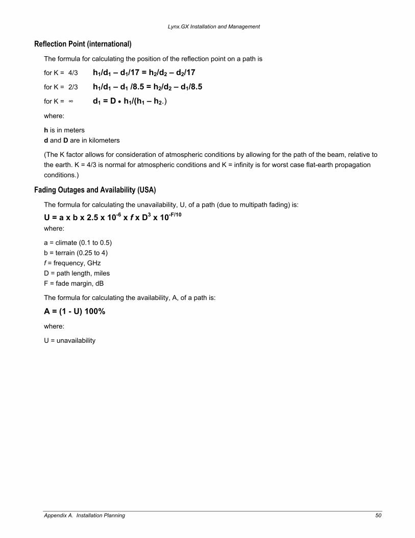
Reflection Point (international)
The formula for calculating the position of the reflection point on a path is
for K = 4/3 h1/d1 – d1/17 = h2/d2 – d2/17
for K = 2/3 h1/d1 – d1 /8.5 = h2/d2 – d1/8.5
for K = ∞ d1 = D • h1/(h1 – h2.)
where:
h is in meters d and D are in kilometers
(The K factor allows for consideration of atmospheric conditions by allowing for the path of the beam, relative to the earth. K = 4/3 is normal for atmospheric conditions and K = infinity is for worst case flat-earth propagation conditions.)
Fading Outages and Availability (USA)
The formula for calculating the unavailability, U, of a path (due to multipath fading) is:
U = a x b x 2.5 x 10⁻⁶ x f x D3 x 10-F/10 where:
a = climate (0.1 to 0.5) b = terrain (0.25 to 4) f = frequency, GHz D = path length, miles F = fade margin, dB
The formula for calculating the availability, A, of a path is:
A = (1 - U) 100%
where:
U = unavailability
Appendix A. Installation Planning 50
Lynx.GX Installation and Management
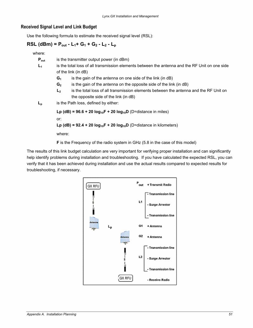
Received Signal Level and Link Budget
Use the following formula to estimate the received signal level (RSL):
RSL (dBm) = Pout - L1+ G1 + G2 - L2 - Lp where:
Pout is the transmitter output power (in dBm) L1 is the total loss of all transmission elements between the antenna and the RF Unit on one side
of the link (in dB) G1 is the gain of the antenna on one side of the link (in dB) G2 is the gain of the antenna on the opposite side of the link (in dB) L2 is the total loss of all transmission elements between the antenna and the RF Unit on
the opposite side of the link (in dB) Lp is the Path loss, defined by either:
Lp (dB) = 96.6 + 20 log10F + 20 log10D (D=distance in miles)
or: Lp (dB) = 92.4 + 20 log10F + 20 log10D (D=distance in kilometers)
where:
F is the Frequency of the radio system in GHz (5.8 in the case of this model)
The results of this link budget calculation are very important for verifying proper installation and can significantly help identify problems during installation and troubleshooting. If you have calculated the expected RSL, you can verify that it has been achieved during installation and use the actual results compared to expected results for troubleshooting, if necessary.
Appendix A. Installation Planning 51
Lynx.GX Installation and Management
In the USA and Canada, this model radio can be installed with any gain directional antennas, as there is no Effective Isotropic Radiated Power (EIRP) limit for the application of these systems for fixed point-to-point applications. In other countries, EIRP limits may apply.
In the case of EIRP limits, use the lesser of either (Pout - L1+ G1) or the EIRP limit within the previous equation. You should check this equation in both directions to assure legal application.
An EIRP limit is the maximum RF energy that can be transmitted, as measured at the transmitting antenna, and is usually determined by government regulations.
EQUIPMENT CO-LOCATION
When configuring radios in a hub or repeater configuration, perform careful engineering of the radio frequency plans and antenna locations to minimize potential interference between the nearby radios.
As a rule of thumb, do not place opposite frequency plan radios (such as A1 and A2) at the same site. Using alternate channels (such as A1 and A2) is highly unlikely to be successful (and therefore not recommended) due to the high level of transmitter-to-receiver isolation required from the antenna system.
In most cases, you should use the same frequency plan (such as A1 and A1) or, in some cases, a different frequency plan from the same side of the band (such as A1 and B1, when more than one channel plan is available).
With careful engineering, you can easily place more than one radio of the same frequency channel plan at the same site. When designing these configurations, antenna size, antenna polarization, and antenna location are critical.
Antenna polarization always should be oriented such that adjacent links are oppositely polarized relative to one another (that is, vertically and horizontally). This provides additional discrimination of the received signals coming into the hub site. If you must place an odd number of links at the same location, ensure that the largest angle is bounded by the two links of like polarization. Further interference analysis may be required to ensure these adjacent links will provide adequate separation.
Changing polarization on the antenna system to the orientation that provides the maximum rejection to the interference is also an extremely effective measure.
The radio must have access to a supply of appropriate power, either DC or AC (if the AC adapter option has been ordered). The unit can be powered from a DC battery system, or from a solar or generator power plant, usually with battery reserves. Typically, either a ± 24 or ± 48 volt supply is used.
For DC, be sure the cable is of sufficient gauge to carry the necessary current and is less than three meters (9.75 feet) in length. A minimum gauge of 14 is recommended.
Before you install the radio, plan for the unit’s continuous power consumption needs. You also should plan for backup power for critical communication circuits. Backup power lets the radios and associated equipment operate continuously when primary power is interrupted.
The radio channel plans are shown in the Specifications document for your radio.
Appendix A. Installation Planning 52

Lynx.GX Installation and Management
PLANNING FOR AND SELECTING IF CABLE
The radio can be installed with the RFU mounted indoors above the IDU in a 19-inch (or 23-inch) rack, or mounted outdoors onto the pole-mounted bracket (sold separately).
For indoor mounting, a short IF coaxial cable is included in the IDU accessory kit to connect the IDU to the RFU; the cable is TNC (male) to TNC (male), about 12 inches in length. A low-loss RF transmission line is required to run the RF signal from the RFU to the antenna (located outdoors atop a tower, monopole, rooftop pole, or cell site. The choices for RF transmission line are discussed in the next section.
For outdoor RFU mounting, a long IF coaxial cable is required to connect the IDU to the RFU outdoors. The recommended cables are listed in the following table. The IF cable shall not exceed 1000 feet (300 meters). Select UV-resistant sheathing on the cable.
IF Transmission Line
Type 1/4-inch coaxial 3/8-inch coaxial
Manufacturer Times Microwave Times Microwave
Model LMR-240 LMR-400
Connectors (needed to connect to RFU and IDU) TC-240-TM “TNC” TC-400-TM “TNC”
Loss* per 100 ft. at 748 MHz IF (up stream) 7.6 dB 3.9 dB
Loss* per 100 ft. at 140 MHz IF (down stream) 3.0 dB 1.5 dB
DC Resistance* per 100 ft. (center conductor plus shield)
0.709 ohms 0.304 ohms
Recommendation for length of cable For cable lengths less than 330 ft or 100 meters
For cable lengths up to 1000 ft. or 300 meters
Radio maximum IF loss: <35 dB at 748 MHz (upstream), <15 dB at 140 MHz (downstream)
Radio maximum DC resistance (center plus shield): < 3.5 ohms
*Source: Times Microwave Systems Communications Coax Selection Guide
Equivalent or lower-loss cable can be used in place of the two cables listed in this table. Be sure to use cable rated for outdoor use (UV-resistant sheathing).
Note: Always apply waterproof butyl tape after the cable has been installed onto the RFU outdoors.
The connectors on both ends should be TNC (male) to TNC (male). Multiple cables can be used to accomplish IDU-to-egress and egress-to-RFU connections, including lightning protection devices. All device losses and resistances (including connectors) must be added and maintained within the limits listed above.
Appendix A. Installation Planning 53

Lynx.GX Installation and Management
PLANNING FOR ANTENNA AND RF TRANSMISSION LINE INSTALLATION
In general, the larger the antenna used with the radio, the better the link performs. Larger antennas have narrower beamwidth and higher gain, which yield better link performance (higher fade margin, better availability) and improve immunity to interference (due to the narrower beamwidths). This is especially important for multi-link installations (hub sites) and for locations with potential interference sources nearby.
However, larger antennas are more costly to purchase and install than smaller antennas and, in some cases, require special installation equipment and more robust mounting structures (due to increased weight and wind loading). You should consider all of these factors when selecting an antenna.
Prior to installation, determine the specific antenna location and mounting. The transmission line should be kept as short as possible, so when line-of-sight placement of antennas allow flexibility, it is always desirable for the equipment to be located closer to the antenna.
This advanced planning, combined with the decision about where the RFU is to be mounted, yields the transmission line requirements.
Note: In areas where transmitted output power restrictions apply, the use of larger antennas benefits narrow beamwidths and receive gain. However, you could be required to reduce output power to meet regulations. Only directional antennas should be used with these radios; typically flat-panel or solid-parabolic antennas. As a general guideline, Proxim Corporation recommends a maximum 3 dB beamwidth of 10 degrees for directional systems.
The following tables list various transmission lines, and then antenna types, performance, and manufacturers.
Within the USA and Canada, antennas other than those illustrated in these tables can be used with this radio, but must be of the same type (flat panel or solid parabolic), dimensions, and gain as those listed in the table. Antennas with gain less than 23.5 dBi are not approved for use within the USA or Canada. Consult governmental regulations or Proxim Corporation for applications outside of the USA or Canada.
For further information regarding antenna installation and adjustment, see “Installing and Adjusting the Antenna” on page 18.
RF Transmission Line (Antenna to RFU)
Type Manufacturer Model Loss* Notes
½-inch foam coaxial Andrew LDF 4-50 6.1 dB Add –0.25 dB per connector 5/8-inch foam coaxial Andrew LDF 4.5-50 4.7 dB Add –0.25 dB per connector
Waveguide Andrew EW-52 1.2 dB Does not include transitions
½-inch foam coaxial Times Microwave LMR-600 7.3 dB Add –0.25 dB per connector 5/8-inch foam coaxial Times Microwave LMR-900 4.9 dB Add –0.25 dB per connector
* per 100 ft. @ 5.8 GHz RF Frequency
Note: Due to potential moding problems, the use of 7/8-inch coaxial cable is NOT recommended for use with these radios above 5 GHz.
Appendix A. Installation Planning 54

Lynx.GX Installation and Management
Antenna Manufacturer Information
Antenna Type Manufacturer Model Number Mid-Band Gain (dBi)
1-foot flat panel Tripoint Global Andrew RFS
DFPD1-52 FPA5250D12-N MA0528-23AN
23.5 23.6 23.0
2-foot flat panel Tripoint Global Andrew RFS
DFPD2-52 FPA5250D24-N MA0528-28AN
28.0 28.2 28.0
2-foot parabolic Tripoint Global Tripoint Global Radio Waves Andrew RFS
QF2-52 HQF2-52 SP2-5.2 P2F-52 SPF2-52A
28.5 28.1 28.3 29.4 27.9
3-foot parabolic Radio Waves Andrew RFS
SP3-5.2 P3F-52 SPF3-52A
31.4 33.4 31,4
4-foot parabolic Tripoint Global Tripoint Global Andrew Radio Waves RFS RFS
QF4-52 HQF4-52 P4F-52 SP4-52 SPF4-52A SDF4-52A
34.2 33.9 34.9 34.6 33.9 33.9
6-foot parabolic Tripoint Global Tripoint Global Radio Waves Andrew RFS RFS
QF6-52 HQF6-5 SP6-5.2 P6F-52 SPF6-52A SDF6-52A
37.5 37.2 37.7 37.6 37.4 37.4
8-foot parabolic Tripoint Global Tripoint Global
SSP8-52A HSSP8-52
39.8 39.6
The formula for determining maximum output power setting for 5.725-5.850 GHz Radio Transmitters (@EIRP=54.5 dBm) is:
Max Tx (dBm) is the lesser of 24.5 dBm and 54.5 - G + FL
where:
G = Antenna Gain Tx = the output power measured at the antenna input FL = feeder loss including loss of connectors
Note: EIRP shall never exceed 54.5 dBm. This is for the compliance to the CFR 47 Part 1.1310 for RF exposure.
Appendix A. Installation Planning 55
Lynx.GX Installation and Management
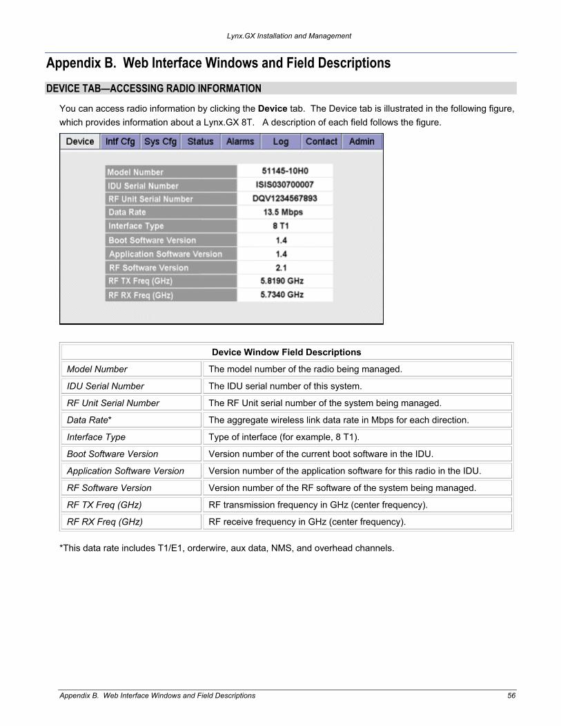
Appendix B. Web Interface Windows and Field Descriptions DEVICE TAB—ACCESSING RADIO INFORMATION
You can access radio information by clicking the Device tab. The Device tab is illustrated in the following figure, which provides information about a Lynx.GX 8T. A description of each field follows the figure.
Device Window Field Descriptions
Model Number The model number of the radio being managed.
IDU Serial Number The IDU serial number of this system.
RF Unit Serial Number The RF Unit serial number of the system being managed.
Data Rate* The aggregate wireless link data rate in Mbps for each direction.
Interface Type Type of interface (for example, 8 T1).
Boot Software Version Version number of the current boot software in the IDU.
Application Software Version Version number of the application software for this radio in the IDU.
RF Software Version Version number of the RF software of the system being managed.
RF TX Freq (GHz) RF transmission frequency in GHz (center frequency).
RF RX Freq (GHz) RF receive frequency in GHz (center frequency).
*This data rate includes T1/E1, orderwire, aux data, NMS, and overhead channels.
Appendix B. Web Interface Windows and Field Descriptions 56
Lynx.GX Installation and Management
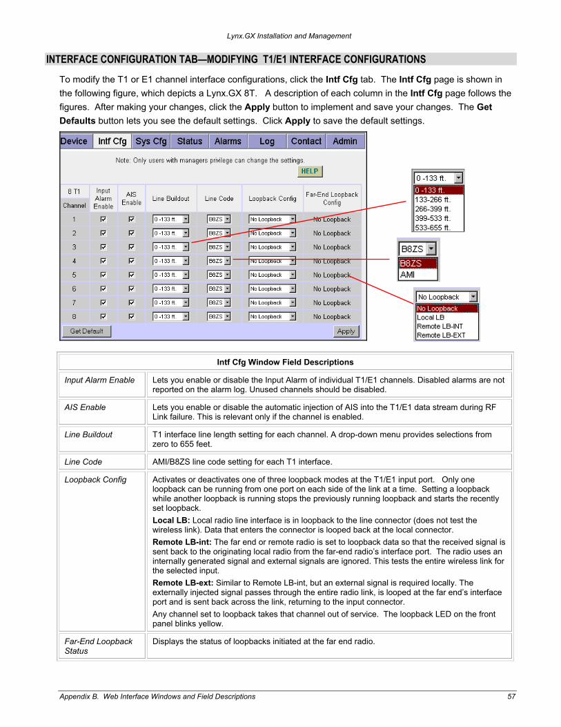
INTERFACE CONFIGURATION TAB—MODIFYING T1/E1 INTERFACE CONFIGURATIONS
To modify the T1 or E1 channel interface configurations, click the Intf Cfg tab. The Intf Cfg page is shown in the following figure, which depicts a Lynx.GX 8T. A description of each column in the Intf Cfg page follows the figures. After making your changes, click the Apply button to implement and save your changes. The Get Defaults button lets you see the default settings. Click Apply to save the default settings.
Intf Cfg Window Field Descriptions
Input Alarm Enable Lets you enable or disable the Input Alarm of individual T1/E1 channels. Disabled alarms are not reported on the alarm log. Unused channels should be disabled.
AIS Enable Lets you enable or disable the automatic injection of AIS into the T1/E1 data stream during RF Link failure. This is relevant only if the channel is enabled.
Line Buildout T1 interface line length setting for each channel. A drop-down menu provides selections from zero to 655 feet.
Line Code AMI/B8ZS line code setting for each T1 interface.
Loopback Config Activates or deactivates one of three loopback modes at the T1/E1 input port. Only one loopback can be running from one port on each side of the link at a time. Setting a loopback while another loopback is running stops the previously running loopback and starts the recently set loopback. Local LB: Local radio line interface is in loopback to the line connector (does not test the wireless link). Data that enters the connector is looped back at the local connector. Remote LB-int: The far end or remote radio is set to loopback data so that the received signal is sent back to the originating local radio from the far-end radio’s interface port. The radio uses an internally generated signal and external signals are ignored. This tests the entire wireless link for the selected input. Remote LB-ext: Similar to Remote LB-int, but an external signal is required locally. The externally injected signal passes through the entire radio link, is looped at the far end’s interface port and is sent back across the link, returning to the input connector. Any channel set to loopback takes that channel out of service. The loopback LED on the front panel blinks yellow.
Far-End Loopback Status
Displays the status of loopbacks initiated at the far end radio.
Appendix B. Web Interface Windows and Field Descriptions 57

Lynx.GX Installation and Management
After entering any configuration changes, click on the Apply button. The Default button installs the default settings for all entries but does not apply them until the Apply button is clicked. Any changes outside the range of acceptable values is identified for the user (with a “Failed to change configuration(s)” message) and the changes fail to apply.
SYSTEM CONFIGURATION TAB—CONFIGURING TX POWER, SECURITY LINK ID, AND TX CHANNEL PLAN Select the Sys Cfg tab to configure transmitter power, orderwire, security, aux port speed, and RF frequency settings. Make one change at a time and click Set.
Sys Cfg Window Field Descriptions Tx Power (dBm) Power setting range in dBm. Choose from +5 to +25 dBm, in 1 dB steps. Orderwire Address The Orderwire telephone address. Choose any 2-digit number from 00 to 99. Link Security Code Security code set by the user; choose 12 characters using an alphanumeric
combination of 0 to 9 and a to f (hexadecimal). This code must match the far end radio to establish the wireless link. Changing the code initiates a 60-second timer for the radio to check and verify the code; the RF link LED will flash red for 60 seconds after the LINK ID is matched. Provides 1216 possible codes (281 trillion). Note: All user data traffic is invalid until the link security code is matched and the LED stops flashing.
Aux Port Speed (bps)
Speed of the auxiliary port in bits per second, in the range of 2.4 kbps to 19.2 kbps. Must match far end radio.
RF Frequency (TX/RX in GHz)
You can select the transmit/receive channel pair in this field. Depending upon the model of the radio, the available choices are listed on the pull down menu. See Technical Specifications on page 69 for information specific to the individual radio models. Depending upon the High or Low model of the RFU, the frequency plans listed here show the transmit frequency on the Low half of the 5.8 GHz band, or the High half of the 5.8 GHz band. High and low frequencies cannot be mixed. Note: Each side of the link must have opposite Tx/Rx values.
External Input Alarm 1 / 2
The external alarm inputs can be set to cause an alarm under an open or closed condition between the appropriate pins on the front panel interface. These fields lets you set the state that is to activate the alarm for external input alarms 1 and 2. Closed is when the input is connected to GND. Open is when the input is not connected to GND.
Appendix B. Web Interface Windows and Field Descriptions 58

Lynx.GX Installation and Management
STATUS TAB—VIEWING CURRENT STATUS
To view the current Near and Far status for the selected unit, click the Status tab. You can click the Near or Far Reset History buttons to clear all data for the corresponding radio, which is useful for resetting the time stamp, such as after installation. A description of each row follows the figure.
Status Window Field Descriptions
Current BER Current estimated received bit error rate (near side measures BER from the far end toward the near end).
Current RSL (~dBm) Current estimated received signal level in dBm.
Errored Seconds Number of seconds that incurred at least one bit error since the last reset.
Severely Errored Seconds Number of seconds that incurred bit errors in excess of BER=10e-3 since the last reset.
Min RSL (~dBm) Minimum estimated received signal level (in dBm) measured since the last reset.
Min RSL Time Stamp The last time at which the minimum estimated RSL value was measured.
Max RSL (~dBm) Maximum estimated received signal level (in dBm) measured since the last reset.
Elapsed Time Since Reset The amount of time since the last system or history reset.
IDU Temperature (Celsius) The current internal temperature of the IDU in Celsius.
RF Unit Temperature (Celsius)
The current internal temperature of the RF Unit in Celsius.
Appendix B. Web Interface Windows and Field Descriptions 59
Lynx.GX Installation and Management
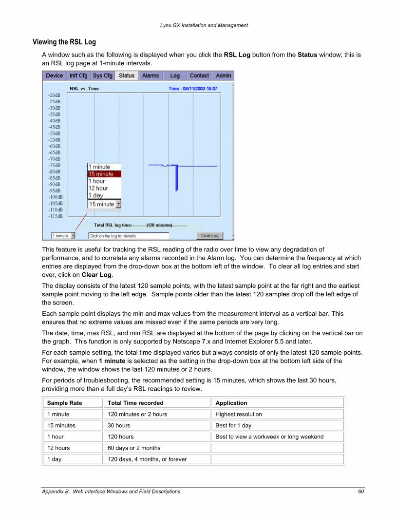
Viewing the RSL Log A window such as the following is displayed when you click the RSL Log button from the Status window; this is an RSL log page at 1-minute intervals.
This feature is useful for tracking the RSL reading of the radio over time to view any degradation of performance, and to correlate any alarms recorded in the Alarm log. You can determine the frequency at which entries are displayed from the drop-down box at the bottom left of the window. To clear all log entries and start over, click on Clear Log. The display consists of the latest 120 sample points, with the latest sample point at the far right and the earliest sample point moving to the left edge. Sample points older than the latest 120 samples drop off the left edge of the screen. Each sample point displays the min and max values from the measurement interval as a vertical bar. This ensures that no extreme values are missed even if the same periods are very long. The date, time, max RSL, and min RSL are displayed at the bottom of the page by clicking on the vertical bar on the graph. This function is only supported by Netscape 7.x and Internet Explorer 5.5 and later. For each sample setting, the total time displayed varies but always consists of only the latest 120 sample points. For example, when 1 minute is selected as the setting in the drop-down box at the bottom left side of the window, the window shows the last 120 minutes or 2 hours. For periods of troubleshooting, the recommended setting is 15 minutes, which shows the last 30 hours, providing more than a full day’s RSL readings to review.
Sample Rate Total Time recorded Application
1 minute 120 minutes or 2 hours Highest resolution
15 minutes 30 hours Best for 1 day
1 hour 120 hours Best to view a workweek or long weekend
12 hours 60 days or 2 months
1 day 120 days, 4 months, or forever
Appendix B. Web Interface Windows and Field Descriptions 60

Lynx.GX Installation and Management
ALARMS TAB—MONITORING LINK STATUS
Click the Alarms tab to monitor both near-end and far-end link alarm status. Field descriptions follow the figures. Note that the orientation of the alarms matches the position of the connectors on the front panel.
These alarms contain some more specific detail than the Front Panel display, and are helpful in determining possible problems.
Alarms Window Field Descriptions
If Grey: If Green: If Yellow: If Red:
T1 Input or E1 Input
Input Alarm is Disabled and T1 or E1 Input is not present
T1 or E1 Input is present and T1/E1 Input Alarm is enabled.
Input Alarm is Disabled and T1 or E1 Input is present
T1 or E1 Input is NOT present and Input Alarm is enabled.
T1 or E1 AIS
NOT injecting all 1s. N/A Injecting all 1s in data stream.
N/A
Radio Sync N/A Radio link is synchronized.
N/A Radio link is NOT established.
Bit Error N/A Error-free operation. Bit Error Rate is between 10e-6 and 10e-3
Bit Error Rate is worse than 10e-3.
Fan Summary
N/A Fans are operating correctly.
One or two fans are malfunctioning.
Two or three fans are malfunctioning.
Major Relay N/A No Major Alarm present
N/A Major Alarm exists
Minor Relay N/A No Minor Alarm present
Minor Alarm exists N/A
External Input Alarm 1 or 2
N/A No External Alarm present
N/A External Alarm exists
Appendix B. Web Interface Windows and Field Descriptions 61
Lynx.GX Installation and Management
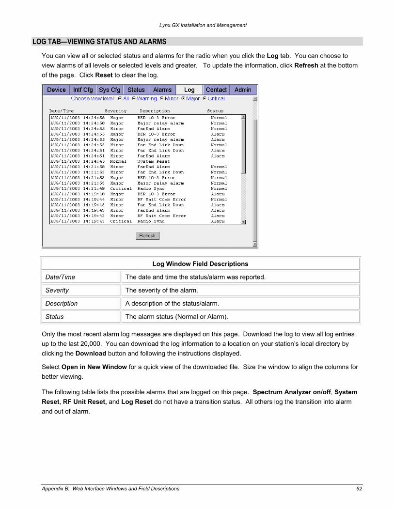
LOG TAB—VIEWING STATUS AND ALARMS
You can view all or selected status and alarms for the radio when you click the Log tab. You can choose to view alarms of all levels or selected levels and greater. To update the information, click Refresh at the bottom of the page. Click Reset to clear the log.
Log Window Field Descriptions
Date/Time The date and time the status/alarm was reported.
Severity The severity of the alarm.
Description A description of the status/alarm.
Status The alarm status (Normal or Alarm).
Only the most recent alarm log messages are displayed on this page. Download the log to view all log entries up to the last 20,000. You can download the log information to a location on your station’s local directory by clicking the Download button and following the instructions displayed.
Select Open in New Window for a quick view of the downloaded file. Size the window to align the columns for better viewing.
The following table lists the possible alarms that are logged on this page. Spectrum Analyzer on/off, System Reset, RF Unit Reset, and Log Reset do not have a transition status. All others log the transition into alarm and out of alarm.
Appendix B. Web Interface Windows and Field Descriptions 62

Lynx.GX Installation and Management
Severity Message Description for Alarm Status
CRITICAL Radio Sync The radio is not communicating to the far end.
MAJOR Major relay alarm The major relay is in alarm (a MAJOR alarm condition exists).
MAJOR Link ID mismatch The link security IDs do not match within the last minute.
MAJOR BER 10-3 Error The wireless link BER has exceeded 10-3.
MAJOR RF Unit Synth Error The RF UNIT Synthesizer has failed.
MAJOR RF Unit Cable The RF Unit Cable has been shorted for more than 5 seconds within the last minute.
MAJOR RF Unit Over Temp RF Unit temperature has exceeded the maximum operating level.
MAJOR RF Unit Low Power The power supplied to the RF Unit is too low.
MAJOR SysBoard Over Temp IDU temperature has exceeded the maximum operating level
MAJOR Loopback Error The internal loopback has measured at least one error.
MAJOR T1/E1 Port X Input (X is between 1 and 16)
Port X has the Input Alarm enabled with no data present.
MAJOR IDU IF Synthesizer alarm The IDU IF Synthesizer has failed.
MINOR Minor relay alarm The minor relay is in alarm (a MINOR alarm condition exists).
MINOR RF Unit Comm Error The RF UNIT has lost communication with the IDU.
MINOR SysBoard Fan Error Two or Three IDU Fans have failed.
MINOR FarEnd Alarm There is a major alarm on the far end radio.
MINOR Far End Link Down The wireless link telemetry is down.
WARNING BER 10-6 Error The wireless link BER has exceeded 10-6.
WARNING SysBoard Fan Warning The IDU Fan Warning status has changed.
WARNING SysBoard Temp Warning The IDU temperature has gone over the warning level.
WARNING External Input Alarm 1 The External Contact Relay 1 is in the alarm state.
WARNING External Input Alarm 2 The External Contact Relay 2 is in the alarm state.
NORMAL System Reset The radio has reset.
NORMAL Log Reset The log was reset from the web interface or SNMP.
NORMAL Spectrum Analyzer on The Spectrum Analyzer function has been started.
NORMAL Spectrum Analyzer off The Spectrum Analyzer function has been stopped.
NORMAL RF Unit Reset The RF Unit has reset.
Appendix B. Web Interface Windows and Field Descriptions 63

Lynx.GX Installation and Management
CONTACT TAB—VIEWING SUPPORT INFORMATION
Click the Contact tab to view Proxim Support information (see “Support” on page 100). If you are connected to the Internet, you can click on the URL or on the Proxim logo to open Proxim’s Internet site, and you can click on the e-mail address to open an e-mail window addressed to Proxim Technical Support.
ADMINISTRATION TAB—CHANGING SYSTEM PASSWORDS, DATE, AND TIME Click the Admin tab to change the system passwords, system date and time, SNMP community strings, and radio IP address information. Click the Set button once you configure each field, except for the three IP-related fields. For these, you can change all three, then press the single Set button next to them. Changing the IP settings causes the system to restart. You must close the browser and logon again with the new IP address. From this page, you also gain access to the Spectrum Analyzer page.
Change the default password (managers) for subsequent entry into the NMS browser. Click on Set after changing the password by entering it two times. If you forget the password, you must reset the IP address and passwords by holding in the FAR END button on the front of the radio while powering it up.
Appendix B. Web Interface Windows and Field Descriptions 64

Lynx.GX Installation and Management
Admin Window Field Descriptions
Monitoring Password
Enter the monitoring password (8 to 15 characters). This is the password for “operator” on the log-in page. To change the password, you must re-enter the password two times. The default is “operator.”
Configuration Password
Enter the configuration password (8 to 15 characters). This is the password for “managers” on the log-in page. Access at this level is required to change settings on the System Configuration and Interface Configuration menus and make changes to the Administration page. To change the password, you must enter the password two times. The default is “managers.”
System Date Set the system date from the drop-down boxes.
System Time Set the system time from the drop-down boxes.
SNMP Get Community
Enter the desired Get community string for the radio’s SNMP network management agent. The default is “public”.
SNMP Set Community
Enter the desired Set community string for the radio’s SNMP network management agent. The default is “private”.
IP Address Enter a new IP address for the network management system. The default is 10.0.0.1
Subnet Mask Enter a new subnet mask for the network management system. The default is 255.0.0.0
Default Gateway Address
Enter a new Gateway address for the network management system. The default is 0.0.0.0
Checking Tx Sources with the Spectrum Analyzer
To enable the built-in Spectrum Analyzer, select the Admin tab and scroll to the bottom of the window.
This spectrum analyzer is a useful feature for checking for transmission sources that the radio is capable of receiving, and for determining whether these emitters could be a source of possible interference.
Click the Spectrum Analyzer button to display the spectrum Analyzer window. The frequency band displayed is what the RF unit is capable of receiving–the low-band half of the 5.8 GHz ISM/UNII band, or the upper half of the 5.8 GHz ISM/UNII band, depending upon which version of the RFU is connected to the near-end radio. The upper half of the 5.8 GHz ISM band is illustrated in the following figure, as indicated by the frequency labels at the top center of the window.
Appendix B. Web Interface Windows and Field Descriptions 65

Lynx.GX Installation and Management
The current status of the Spectrum Analyzer is indicated on the bottom. When this menu is first turned on the analyzer is not running. To start the analyzer, click on the Start button.
The Spectrum Analyzer interrupts traffic on the near end because it is analyzing the spectrum. The far-end radio is still receiving from the near-end transmitter. Click Start to run the Spectrum Analyzer; it completes a scan within a few minutes and displays the data as it is processed.
A window such as the following is displayed. Note that the unit is in RED alarm.
Appendix B. Web Interface Windows and Field Descriptions 66

Lynx.GX Installation and Management
There are 25 bars across the screen, representing 25 measured points spaced 2 MHZ apart from the left of the display (in this example, 5.721 GHz) to the right of the display (5.769 GHz). The height of the red bar indicates the highest level of the received signal at that frequency. The height of the green bar is the lowest level of the received signal at that frequency.
In this example, the far end transmitter of an RF unit was switched on, and the transmit emission mask is displayed. Normally, the far-end transmitter should be powered off so that any signals received by the spectrum analyzer can be viewed as potential interferers. The analyzer will continue to scan across the band from lower frequency (left side of the display) to higher frequency (right side of the display) until stopped by the operator.
WARNING! Starting the Spectrum Analyzer is a service-disrupting activity.
In this example, the far end transmitter was muted about a third of the way through a scan; this is indicated by the start of the red bars. The height of the received signal dropped to the noise floor of the receiver, and then rose again when the transmitter was turned on again.
The Spectrum Analyzer runs until you click on Stop. If you leave the web page, the Spectrum Analyzer self-terminates after 10 minutes. To turn off the Spectrum Analyzer, click on Stop. Stopping the analyzer also clears the display. You also can begin a new graph by clicking Reset.
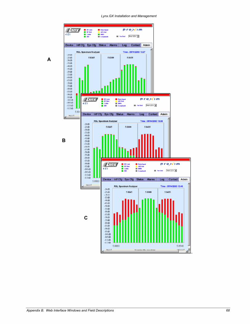
The following are sample RSL Spectrum Analyzer graphs from the Lynx.GX 4E (unbalanced).
Graph A is the presentation on the spectrum analyzer when enabled for receive channel 5.8435 GHz, and then switched to receive channel 5.8165 GHz. This graph is captured halfway through a scan, as evidenced by the increasing heights of the green bars left to right. The red bars indicate the highest value scanned and the green bars indicate the current value scanned. The frequency channel selection was changed on the SysCfg menu.
Graph B shows the spectrum analyzer completing a full scan of both the 5.8435 and 5.8165 GHz channels.
Graph C shows the spectrum analyzer completing a full can of all three receive channels, 5.8165, 5.830, and 5.8435 GHz.
Appendix B. Web Interface Windows and Field Descriptions 67
Lynx.GX Installation and Management
A
B
C
Appendix B. Web Interface Windows and Field Descriptions 68

Lynx.GX Installation and Management
Appendix C. Lynx.GX Front Panel and Connections MODELS
This information in this appendix applies to the following Lynx.GX models.
Model Number Item Number Ports Frequency Band Compliance
301-51850-10L0 301-51850-10H0
62291 62292
4 T1 ports RJ-48C
5.8 GHz ISM
301-51850-20L0 301-51850-20H0
62294 62295
4 E1 ports, balanced RJ45
5.8 GHz ISM
301-51850-30L0 301-51850-30H0
64749 64751
4 E1 ports, unbalancedBNC
5.8 GHz ISM
301-51145-10L0 301-51145-10H0
62139 62142
8 T1 ports RJ-48C
5.8 GHz ISM
301-51145-20L0 301-51145-20H0
62144 62145
8 E1 ports, balanced RJ45
5.8 GHz ISM
301-52290-10L0 301-52290-10H0
62284 62286
16 T1 ports RJ-48C
5.8 GHz ISM
BASIC SPECIFICATIONS
4T Basic specifications for the Lynx.GX 4T are as follows:
Output Power ................................... ≥ 23 dBm Channel Pairs................................... 3 Main Interface Connectors ............... RJ-45 with Activity LED Aggregate Capacity.......................... 9 Mbps Line Code/Channel .......................... AMI/B8ZS Line Build-out/Channel..................... 0-655 feet, selectable
4E Balanced Output Power ................................... ≥ 23 dBm Channel Pairs................................... 3 Main Interface Connectors ............... Balanced: RJ-45, SB RJ-45 with Activity LED Aggregate Capacity.......................... 9 Mbps Line Code/Channel .......................... HDB3 Line Build-out/Channel..................... N/A
4E Unbalanced Output Power ................................... ≥ 23 dBm Channel Pairs................................... 3 Main Interface Connectors ............... Unbalanced: CEPT-1 [4xBNC] SB [8xBNC] (4TX and 4RX BNCs) Aggregate Capacity.......................... 9 Mbps Line Code/Channel .......................... HDB3 Line Build-out/Channel..................... N/A
Appendix C. Lynx.GX Front Panel and Connections 69

Lynx.GX Installation and Management
8T Output Power ................................... ≥ 23 dBm Channel Pairs................................... 2 Main Interface Connectors ............... RJ-48C with Activity LED Aggregate Capacity.......................... 13.5 Mbps Line Code/Channel .......................... AMI/B8ZS Line Build-out/Channel..................... 0-655 feet, selectable
8E Balanced Output Power ................................... ≥ 23 dBm Channel Pairs................................... 1 Main Interface Connectors ............... RJ-48C with Activity LED, SB RJ-45 Aggregate Capacity.......................... 27 Mbps Line Code/Channel .......................... HDB3 Line Build-out/Channel..................... N/A
16T Output Power.......................................... ≥ 23 dBm Channel Pairs ................................................1 Main Interface Connectors .............................RJ-48C with Activity LED Aggregate Capacity .......................................27 Mbps Line Code/Channel ........................................AMI/B8ZS Line Build-out/Channel ........................... 0-655 feet, selectable
CHANNEL PLANS
Lynx.GX Model Channel Plan Transmit Frequency
301-51850-10L0 4T A1 B1 C1
5731.5 MHz 5745 MHz 5758.5 MHz
301-51850-10H0 4T A2 B2 C2
5816.5 MHz 5830 MHz 5843.5 MHz
301-51850-20L0 301-51850-30L0
4E A1 B1 C1
5731.5 MHz 5745 MHz 5758.5 MHz
301-51850-20H0 301-51850-30H0
4E A2 B2 C2
5816.5 MHz 5830 MHz 5843.5 MHz
301-51145-10L0 8T A1 B1
5734 MHz 5756 MHz
301-51145-10H0 8T A2 B2
5819 MHz 5841 MHz
301-51145-20L0 8E A1 5745 MHz
301-51145-20H0 8E A2 5830 MHz
301-52290-10L0 16T A1 5745 MHz 301-52290-10H0 16T A2 5830 MHz
Appendix C. Lynx.GX Front Panel and Connections 70
Lynx.GX Installation and Management
LYNX.GX FRONT PANEL
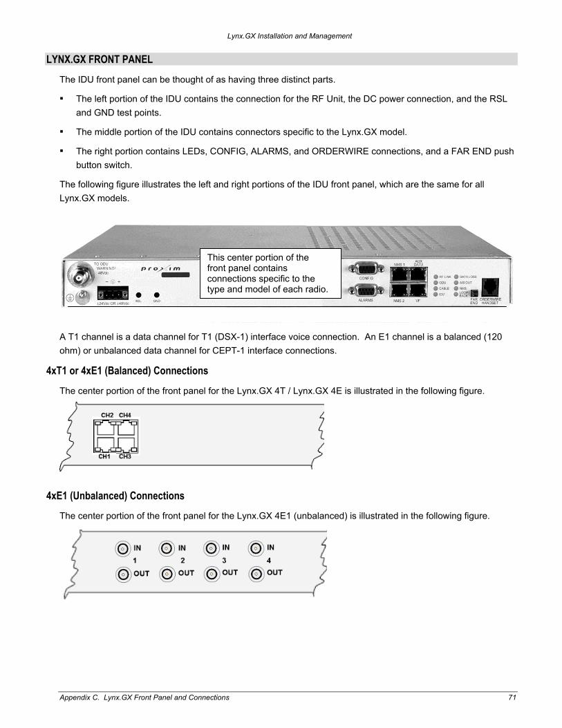
The IDU front panel can be thought of as having three distinct parts.
The left portion of the IDU contains the connection for the RF Unit, the DC power connection, and the RSL and GND test points.
The middle portion of the IDU contains connectors specific to the Lynx.GX model.
The right portion contains LEDs, CONFIG, ALARMS, and ORDERWIRE connections, and a FAR END push button switch.
The following figure illustrates the left and right portions of the IDU front panel, which are the same for all Lynx.GX models.
A T1 channel is a data channel for T1 (DSX-1) interface voice connection. An E1 channel is a balanced (120 ohm) or unbalanced data channel for CEPT-1 interface connections.
This center portion of the front panel contains connections specific to the type and model of each radio.
4xT1 or 4xE1 (Balanced) Connections
The center portion of the front panel for the Lynx.GX 4T / Lynx.GX 4E is illustrated in the following figure.
4xE1 (Unbalanced) Connections The center portion of the front panel for the Lynx.GX 4E1 (unbalanced) is illustrated in the following figure.
Appendix C. Lynx.GX Front Panel and Connections 71
Lynx.GX Installation and Management
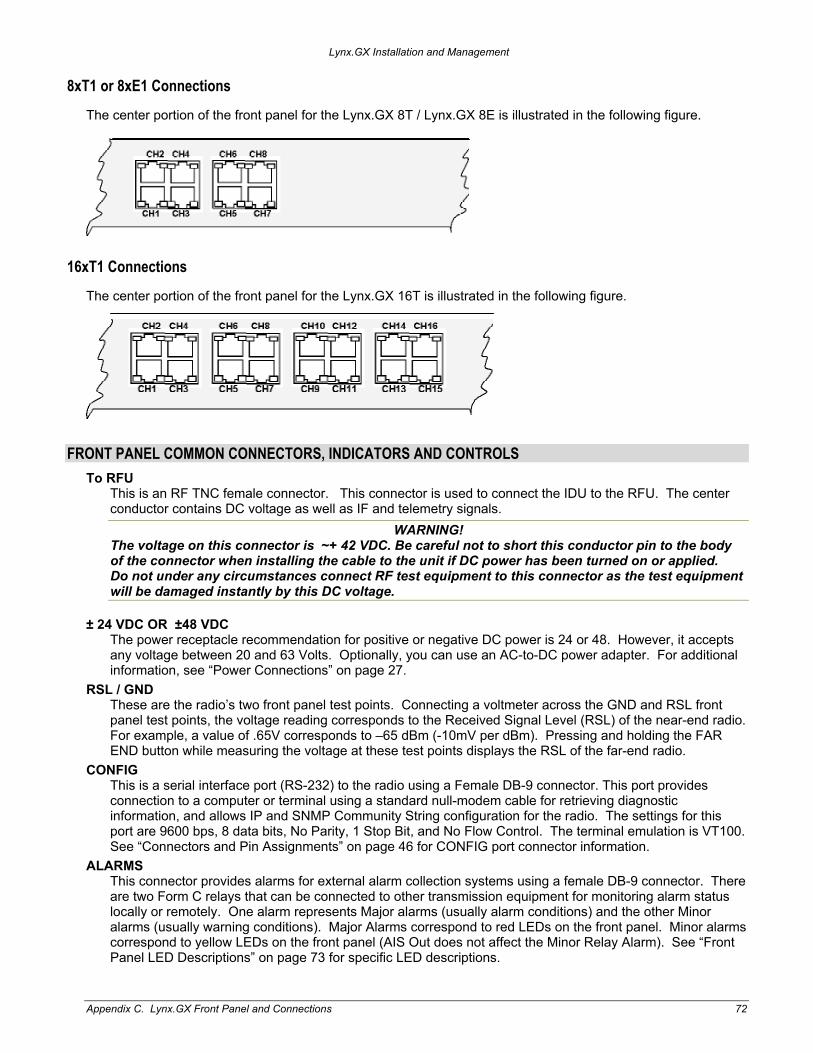
8xT1 or 8xE1 Connections
The center portion of the front panel for the Lynx.GX 8T / Lynx.GX 8E is illustrated in the following figure.
16xT1 Connections
The center portion of the front panel for the Lynx.GX 16T is illustrated in the following figure.
FRONT PANEL COMMON CONNECTORS, INDICATORS AND CONTROLS To RFU
This is an RF TNC female connector. This connector is used to connect the IDU to the RFU. The center conductor contains DC voltage as well as IF and telemetry signals.
WARNING! The voltage on this connector is ~+ 42 VDC. Be careful not to short this conductor pin to the body of the connector when installing the cable to the unit if DC power has been turned on or applied. Do not under any circumstances connect RF test equipment to this connector as the test equipment will be damaged instantly by this DC voltage.
± 24 VDC OR ±48 VDC The power receptacle recommendation for positive or negative DC power is 24 or 48. However, it accepts any voltage between 20 and 63 Volts. Optionally, you can use an AC-to-DC power adapter. For additional information, see “Power Connections” on page 27.
RSL / GND These are the radio’s two front panel test points. Connecting a voltmeter across the GND and RSL front panel test points, the voltage reading corresponds to the Received Signal Level (RSL) of the near-end radio. For example, a value of .65V corresponds to –65 dBm (-10mV per dBm). Pressing and holding the FAR END button while measuring the voltage at these test points displays the RSL of the far-end radio.
CONFIG This is a serial interface port (RS-232) to the radio using a Female DB-9 connector. This port provides connection to a computer or terminal using a standard null-modem cable for retrieving diagnostic information, and allows IP and SNMP Community String configuration for the radio. The settings for this port are 9600 bps, 8 data bits, No Parity, 1 Stop Bit, and No Flow Control. The terminal emulation is VT100. See “Connectors and Pin Assignments” on page 46 for CONFIG port connector information.
ALARMS This connector provides alarms for external alarm collection systems using a female DB-9 connector. There are two Form C relays that can be connected to other transmission equipment for monitoring alarm status locally or remotely. One alarm represents Major alarms (usually alarm conditions) and the other Minor alarms (usually warning conditions). Major Alarms correspond to red LEDs on the front panel. Minor alarms correspond to yellow LEDs on the front panel (AIS Out does not affect the Minor Relay Alarm). See “Front Panel LED Descriptions” on page 73 for specific LED descriptions.
Appendix C. Lynx.GX Front Panel and Connections 72

Lynx.GX Installation and Management
There are two external input alarms, independent of the relay outputs available. From the SysCfg page, you can set whether an open or closed condition produces an alarm. See the table of alarms in “Log Tab: Viewing Status and Alarms” on page 62. See “Connectors and Pin Assignments” on page 46 for ALARM port connector information.
NMS1 and NMS2 There are two Ethernet 10/100 Base-TX connections (both switched) for access to the Network Management System (NMS) using SNMP, HTTP, or Telnet. Both of these connections auto-negotiate speed and duplex, and auto-sense MDI or MDI-X connections. On GX radios, the two 10/100BT ports are identical, and can be used to daisy chain the NMS connections between units at a hub location or to connect to other local Ethernet devices. See “Providing a Contiguous Management Link” on page 33.
AUX DATA This is a serial interface port (RS-232) using an RJ-45 connector, supporting speeds from 2400 to 19200 baud (set through the NMS). This allows auxiliary serial data connection from one end of the wireless link to the other, completely separate and independent of the main bearer channel. It can be used for separate data connections for serial devices. See “Connectors and Pin Assignments” on page 46 for AUX DATA port connector information. Note that the aux data rate must be configured using the Web interface before use.
VF (Voice Frequency) This RJ-45 connector is used to link two radios at a repeater site for Orderwire operation or to connect to an external Orderwire system. This allows Orderwire calls to and from any point in the network that is connected. The circuit is a 4-wire audio (2xTX and 2xRX) configuration. All phones off-hook hear and participate in the call (behave as a ‘party line’). The NMS provides Orderwire addressing capability for individual radio terminal signaling. See “Connectors and Pin Assignments” on page 46 for VF port connector information.
Front Panel LED Descriptions
Front Panel LEDs
LED Color Description
RF Link Green Yellow Red Flashing Red
BER<10^-6 Bit errors occurring (when 10^-6 ≤ BER ≤ 10^-3) Excessive bit errors or radio link failure (BER ≥ 10^-3 or sync loss) Link Security ID mismatch within the last minute
RF Unit Green Red
RF UNIT OK RF UNIT alarm (Over-temp (>95°C), IDU to RFU communication failure, DC power loss, or RFU detected hardware failure.)
Cable Green Red
Cable between system board and RF UNIT is OK Cable short longer than 5 seconds detected in the last minute
IDU Green Yellow Red
IDU OK IDU warning (warning condition in IDU (over-temp or a fan failed) IDU alarm (all fans failed or over-temp (>65°C)
DATA INPUT (listed by priority)
Red Yellow Green Off
Input Alarm enabled; data not present on at least one enabled channel Input Alarm disabled; data present on at least one channel Input Alarm enabled; data present on all enabled channels Input Alarm disabled; data not present on any channels
AIS OUT Off Yellow
Not injecting AIS (Alarm Indication Signal, or all ones) in data stream Injecting AIS in data stream
NMS Green Off
Tx or Rx NMS data present on the interface No NMS interface connection detected or no data present
LOOPBACK Flashing Yellow Solid Yellow Off
At least one data channel in loopback Internal loopback is on and has detected at least one error No loopbacks on any channels
Appendix C. Lynx.GX Front Panel and Connections 73

Lynx.GX Installation and Management
FAR END When the LED on this button is red, alarms exist on the far-end radio. Press and hold the button to view those alarms on this radio’s front panel. If the far-end radio is not available, such as when the link is down, all LEDs flash red.
Note: Pressing and holding this button while powering on the radio resets the IP address settings and passwords to default values.
ORDERWIRE Port This connection is used to access the electronic orderwire function (a facility for telephone style service from one radio to another). A standard analog telephone (with an electronic ringer) plugs into this RJ-11 connector. You can dial the orderwire address of the far-end radio (or any radio in the network) to cause that radio and any connected orderwire phone to ring; however, communications is automatically established when both telephones are lifted off hook.
This communication does not interrupt or interfere with the other radio communications. The radio link must be operational to use this facility. The orderwire feature can be very useful for installation, maintenance, and troubleshooting.
Note: All radios connected to the same orderwire network should have unique address settings (telephone numbers) to facilitate proper signaling.
Rear Panel LED The rear panel of the IDU has a single LED that reflects the summary state of the radio, exactly copying the status bar on the Web browser interface (see “Front Panel LEDs” on page 73). The LED is red when any alarm is active or the front panel LED is red, yellow when any front panel LED is yellow and none are red, and green if all front panel LEDs are green or off.
Appendix C. Lynx.GX Front Panel and Connections 74

Lynx.GX Installation and Management
Appendix D. Connectors and Pin Assignments This section describes the radio port connectors and pin assignments for the IDU (Indoor Unit) and RFU (Radio Frequency Unit).
IDU MAIN TRAFFIC T1/E1 CONNECTORS
The main traffic ports for T1 or E1 connections appear on the front panel as multiple 8-pin modular jack connectors wired per RJ-48C. The following figures show the actual format and layout of the T1/E1 connectors (the 16T model is depicted), an illustration of the traffic port pin assignment, and a table listing the pin assignment descriptions.
Figure 5. Port Connector Layout for 16 T1 Ports
Each connector has a green LED on the right side of the connector that illuminates when a T1 or E1 signal is received at that port. The left LED is not used. The upper row has the connector tab in the up position, whereas the lower row has the connector tab on the bottom position. The front view is illustrated.
T1/E1 Port Connector Pin Assignment Description
Pin Description Signal Pin Description Signal
1 T1/E1 OUT-tip: Line transmit out (tip) Output 5 T1/E1 IN-ring: Line receive in (ring) Input
2 T1/E1 OUT-ring: Line transmit out (ring)
Output 6 GND: Chassis Ground
3 GND: Chassis Ground 7 NC: No Connection
4 T1/E1 IN-tip: Line receive in (tip) Input 8 NC: No Connection
Appendix D Connectors and Pin Assignments 75
Lynx.GX Installation and Management
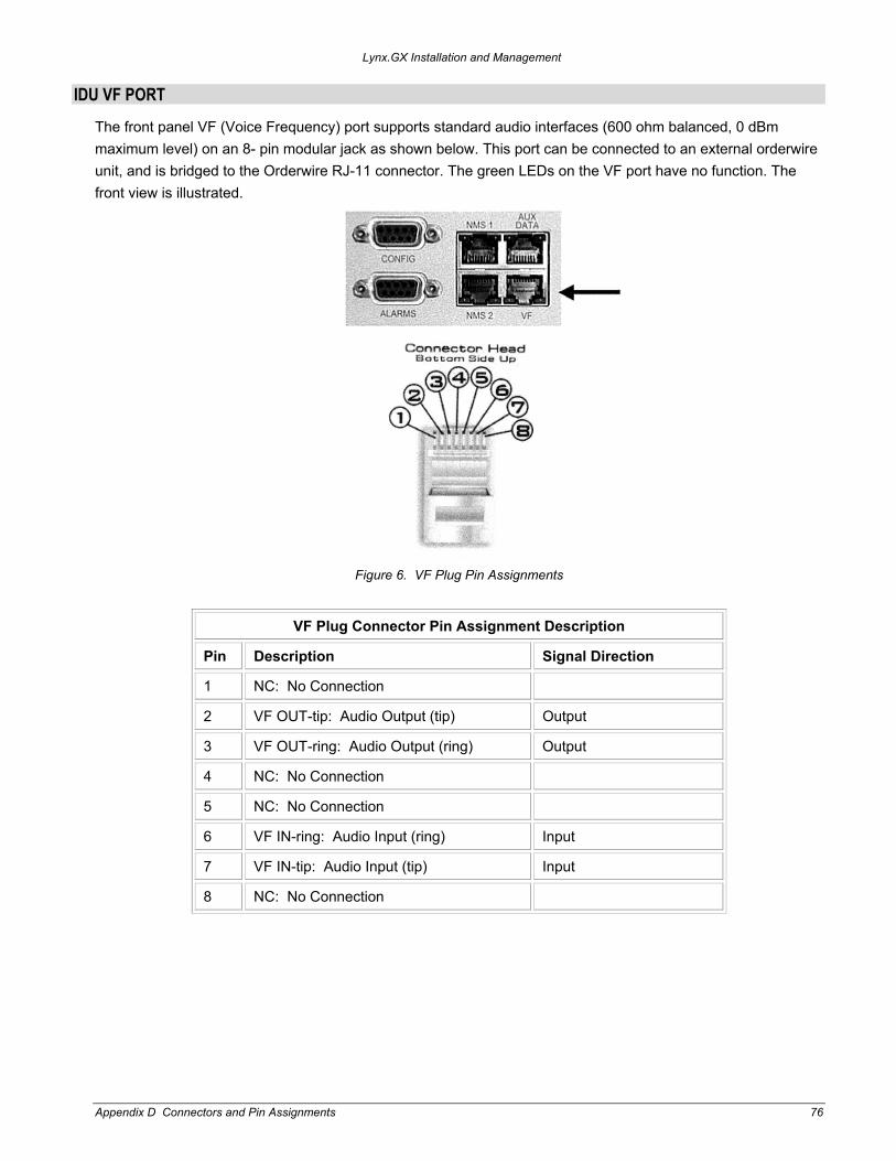
IDU VF PORT
The front panel VF (Voice Frequency) port supports standard audio interfaces (600 ohm balanced, 0 dBm maximum level) on an 8- pin modular jack as shown below. This port can be connected to an external orderwire unit, and is bridged to the Orderwire RJ-11 connector. The green LEDs on the VF port have no function. The front view is illustrated.
Figure 6. VF Plug Pin Assignments
VF Plug Connector Pin Assignment Description
Pin Description Signal Direction
1 NC: No Connection
2 VF OUT-tip: Audio Output (tip) Output
3 VF OUT-ring: Audio Output (ring) Output
4 NC: No Connection
5 NC: No Connection
6 VF IN-ring: Audio Input (ring) Input
7 VF IN-tip: Audio Input (tip) Input
8 NC: No Connection
Appendix D Connectors and Pin Assignments 76

Lynx.GX Installation and Management
IDU AUX DATA PORT CONNECTOR (DCE PORT)
The front panel Aux (Auxiliary) Data Port supports EIA-561 (electrical wiring standard) serial data on an 8-pin modular jack as shown below. The data rate is user selectable to 2400, 4800, 9600, or 19,200 bps. The asynchronous data is configured for 1 start bit, 8 data bits, no parity, and 1 stop bit. The green LEDs on the Aux Data port have no function. The front view is illustrated.
Note: Pins 2 and 7 are not used on the AUX DATA port of the radio. The user may connect a digital signal to these pins; however, operation of this data port is not affected.
Figure 7. Aux Plug Pin Assignments
Aux Data Plug Connector Pin Assignment Description
Pin Description Signal Direction
1 NC: No Connection
2 +3.3 V (Data Set Ready)
3 +3.3 V (DTE)
4 Common Signal/Chassis Ground Gnd
5 Aux Data Out Output
6 Aux Data In Input
7 +3.3 V (Clear To Send)
8 +3.3 V (RTS)
Appendix D Connectors and Pin Assignments 77

Lynx.GX Installation and Management
IDU NMS PORT CONNECTORS
The two front panel NMS (Network Management System) Port connectors (NMS1 and NMS2) support 10/100BaseT Ethernet serial data using two 8-pin modular jack connectors. Shown below is the wiring for each connector per USOC 568B. Two jacks permit bridging to other Ethernet devices without the need for an additional Ethernet hub or switch. The left LED on each connector will illuminate to indicate that the NMS connection is on, and the right LED indicates green for full duplex and off for half duplex (the LED will flash green to indicate collisions in half duplex mode). The front view is illustrated.
Figure 8. NMS Plug Pin Assignment
NMS Plug Connector Pin Assignment Description
Pin Description Signal Direction
1 NMS Data Out + Output
2 NMS Data Out - Output
3 NMS Data In + Input
4 * (connected to cross-talk suppression circuits)
5 *
6 NMS Data In - Input
7 *
8 *
Appendix D Connectors and Pin Assignments 78

Lynx.GX Installation and Management
IDU ALARM PORT CONNECTOR
External alarm outputs are provided using the 9-pin, D-type (DB-9) ALARM female connector. Two Form C alarm relays capable of switching 30 VDC at 1A are provided. Both relays are energized in the normal state and de-energized in the alarm state. The two relay alarms are:
Major or “Out-of-Service” alarm is activated by any red alarm. This is also indicated by the “bar” alarm indicator on the GUI.
Minor or “Summary” alarm is activated by any yellow alarm except AIS OUT.
Two external relay inputs are available and can be set on the SysCfg page. By default, shorting the alarm pin to ground (close condition) causes the external alarm to display on the web page or in SNMP. This can be changed on the SysCfg page to make the open condition cause the alarm.
Note: All alarms are active for a minimum of one second, or as long as the alarm condition persists, which ever is longer duration.
Figure 9. Alarm Plug Pin Assignment
Alarm Plug Connector Pin Assignment Description – Front View
Pin Description
1 NO, Minor Alarm, Form C: normally open connection. Closed when in alarm.
2 NC, Minor Alarm, Form C: normally closed connection. Open when in alarm
3 COMMON CHASSIS/SIGNAL GROUND.
4 NO, Major Summary Alarm, Form C: normally open connection. Closed when in alarm.
5 NC, Major Summary Alarm, Form C: normally closed connection. Open when in alarm.
6 Common, Minor Alarm, Form C: common connection on the minor alarm relay.
7 External Input Alarm 1 (used with NMS alarm and SNMP only)
8 External Input Alarm 2 (used with NMS alarm and SNMP only)
9 Common, Major Summary Alarm, Form C: common connection for the major summary alarm relay.
Appendix D Connectors and Pin Assignments 79
Lynx.GX Installation and Management
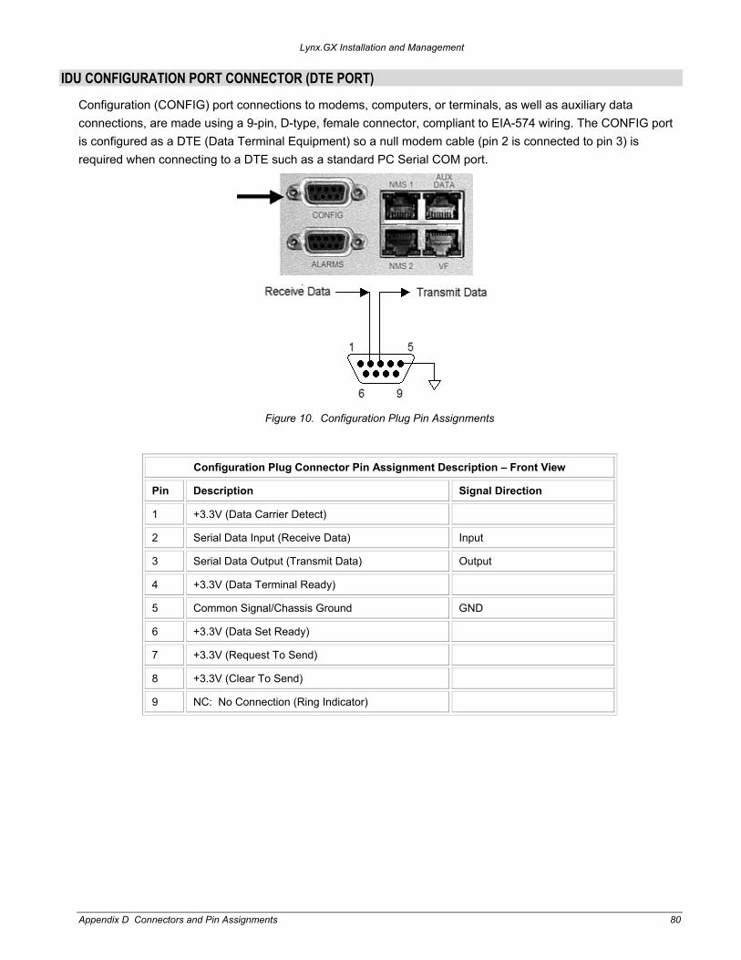
IDU CONFIGURATION PORT CONNECTOR (DTE PORT)
Configuration (CONFIG) port connections to modems, computers, or terminals, as well as auxiliary data connections, are made using a 9-pin, D-type, female connector, compliant to EIA-574 wiring. The CONFIG port is configured as a DTE (Data Terminal Equipment) so a null modem cable (pin 2 is connected to pin 3) is required when connecting to a DTE such as a standard PC Serial COM port.
Figure 10. Configuration Plug Pin Assignments
Configuration Plug Connector Pin Assignment Description – Front View
Pin Description Signal Direction
1 +3.3V (Data Carrier Detect)
2 Serial Data Input (Receive Data) Input
3 Serial Data Output (Transmit Data) Output
4 +3.3V (Data Terminal Ready)
5 Common Signal/Chassis Ground GND
6 +3.3V (Data Set Ready)
7 +3.3V (Request To Send)
8 +3.3V (Clear To Send)
9 NC: No Connection (Ring Indicator)
Appendix D Connectors and Pin Assignments 80

Lynx.GX Installation and Management
IDU ORDERWIRE PORT CONNECTOR
The IDU front panel Orderwire telephone port supports connection to standard electronic ringer telephones on a 6-pin RJ-11 modular jack as shown below. The center two pins (pins 3 and 4) are used for the Tip and Ring. Telephones with RJ-11 modular plugs can be 6-, 4-, or 2-pin modular plugs. The center two pins are used on the phone regardless of the number of pins on the modular plug
. Figure 11. Orderwire RJ-11 Modular Plug (typical termination)
Note: If you are using a standard telephone (for orderwire function) not provided by Proxim with this product, ensure that the telephone has a ringing equivalency specification of 1.0 Baud and is a UL-Listed (ITE) device that has been evaluated to the Standard for the Safety of Information Technology Equipment, including Electrical Business Equipment, CAN/CSA C22.2, No. 950-85 * UL 1950, Third Edition.
IDU/RFU CABLE CONNECTOR AND PIN ASSIGNMENT
The IDU (Indoor Unit) is connected to the RF Unit using a 50-ohm coaxial cable terminated with male TNC (Threaded Neill Concelman) connectors on each end. The female TNC connector provides termination for this coaxial cable on both the IDU front panel and RFU enclosures. The single coaxial cable carries power, telemetry, receive IF signals, and transmit IF signals between the IDU and the RFU.
Figure 12. IDU/RFU Cable Connector
TNC Port Connector Pin Assignment Description
Pin Description
Center + 42 VDC, 125 kHz Telemetry, 140 MHz Receiver IF, 748 MHz Transmitter IF
Outer Common Signal/Chassis Ground
Appendix D Connectors and Pin Assignments 81
Lynx.GX Installation and Management
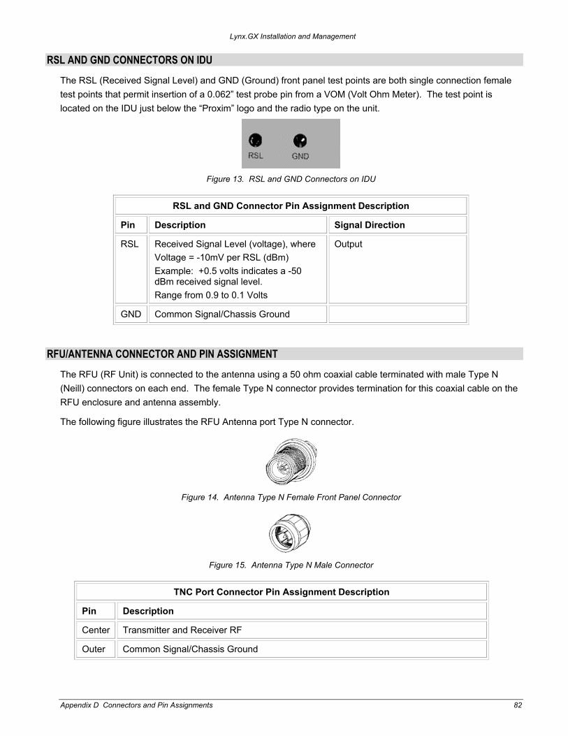
RSL AND GND CONNECTORS ON IDU
The RSL (Received Signal Level) and GND (Ground) front panel test points are both single connection female test points that permit insertion of a 0.062” test probe pin from a VOM (Volt Ohm Meter). The test point is located on the IDU just below the “Proxim” logo and the radio type on the unit.
Figure 13. RSL and GND Connectors on IDU
RSL and GND Connector Pin Assignment Description
Pin Description Signal Direction
RSL Received Signal Level (voltage), where Voltage = -10mV per RSL (dBm) Example: +0.5 volts indicates a -50 dBm received signal level. Range from 0.9 to 0.1 Volts
Output
GND Common Signal/Chassis Ground
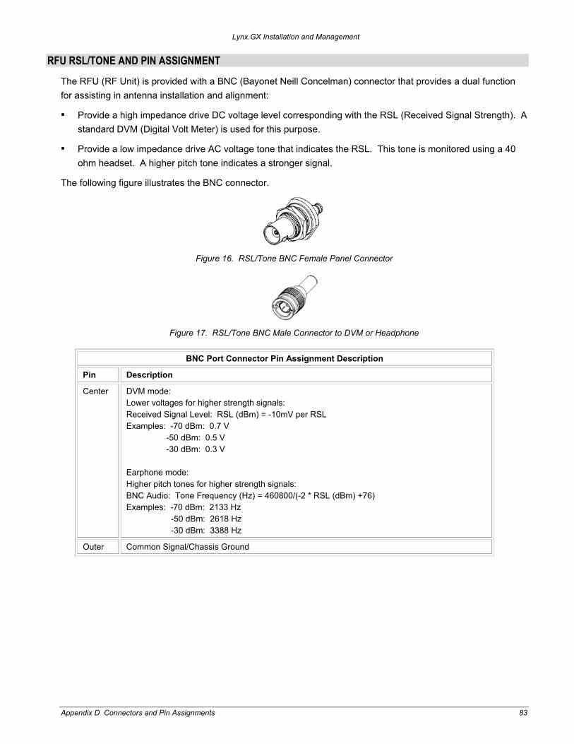
RFU/ANTENNA CONNECTOR AND PIN ASSIGNMENT
The RFU (RF Unit) is connected to the antenna using a 50 ohm coaxial cable terminated with male Type N (Neill) connectors on each end. The female Type N connector provides termination for this coaxial cable on the RFU enclosure and antenna assembly.
The following figure illustrates the RFU Antenna port Type N connector.
Figure 14. Antenna Type N Female Front Panel Connector
Figure 15. Antenna Type N Male Connector
TNC Port Connector Pin Assignment Description
Pin Description
Center Transmitter and Receiver RF
Outer Common Signal/Chassis Ground
Appendix D Connectors and Pin Assignments 82
Lynx.GX Installation and Management
RFU RSL/TONE AND PIN ASSIGNMENT
The RFU (RF Unit) is provided with a BNC (Bayonet Neill Concelman) connector that provides a dual function for assisting in antenna installation and alignment:
Provide a high impedance drive DC voltage level corresponding with the RSL (Received Signal Strength). A standard DVM (Digital Volt Meter) is used for this purpose.
Provide a low impedance drive AC voltage tone that indicates the RSL. This tone is monitored using a 40 ohm headset. A higher pitch tone indicates a stronger signal.
The following figure illustrates the BNC connector.
Figure 16. RSL/Tone BNC Female Panel Connector
Figure 17. RSL/Tone BNC Male Connector to DVM or Headphone
BNC Port Connector Pin Assignment Description
Pin Description
Center DVM mode: Lower voltages for higher strength signals: Received Signal Level: RSL (dBm) = -10mV per RSL Examples: -70 dBm: 0.7 V -50 dBm: 0.5 V -30 dBm: 0.3 V Earphone mode: Higher pitch tones for higher strength signals: BNC Audio: Tone Frequency (Hz) = 460800/(-2 * RSL (dBm) +76) Examples: -70 dBm: 2133 Hz -50 dBm: 2618 Hz -30 dBm: 3388 Hz
Outer Common Signal/Chassis Ground
Appendix D Connectors and Pin Assignments 83

Lynx.GX Installation and Management
Appendix E. Spares and Accessories The following optional spares and accessories are available for purchase for your Lynx.GX radio.
Order # Model # Product Description Contents
67265 301-52000-H GX RF UNIT SPARE 5.8GHz ISM HIGH A single RFU 5.8GHz ISM high with no accessories
67264 301-52000-L GX RF UNIT SPARE 5.8GHz ISM LOW A single RFU 5.8GHz ISM low with no accessories
67263 ACC-GX-3 GX IDU INSTALLATION KIT SPARE Screws, brackets, and cable needed to install an RF unit in a 19” or 23” rack
67262 ACC-GX-4 GX RF UNIT INDOOR INSTALLATION KIT SPARE
Screws, brackets, and cable needed to install an RF unit in a 19” or 23” rack
61688 ACC-RX-RF-2 GX RF UNIT OUTDOOR MOUNTING KIT A single mounting bracket, screws, clamps, cable needed to mount an RFU outdoors
62427 201-31075-1 AC POWER ADAPTER, 110/220 VAC, WITH CONNECTOR
One AC-to-DC 110/220 VAC Power Adapter with DC cable
67446 ACC-GX-5 GX BNC TO STD STEREO HEADPHONE CABLE
A single cable that converts BNC to a Standard 6.3mm stereo headphone jack; use for audio antenna alignment
67269 301-51850-10 GX IDU SPARE LYNX 4XT1 A single Lynx.GX 4T IDU with no accessories
67270 301-51850-20 GX IDU SPARE LYNX 4XE1 BALANCED, RJ48C
A single Lynx.GX 4E IDU with no accessories
67271 301-51850-30 GX IDU SPARE LYNX 4XE1 UNBALANCED, BNC
A single Lynx.GX 4E IDU with no accessories
67267 301-51145-10 GX IDU SPARE, LYNX 8XT1 A single Lynx.GX 8T IDU with no accessories
67268 301-51145-20 GX IDU SPARE, LYNX 8XE1 A single Lynx.GX 8E IDU with no accessories
67266 301-52290-10 GX IDU SPARE, LYNX 16XT1 A single Lynx.GX 16T IDU with no accessories
Appendix E. Spares and Accessories 84
Lynx.GX Installation and Management
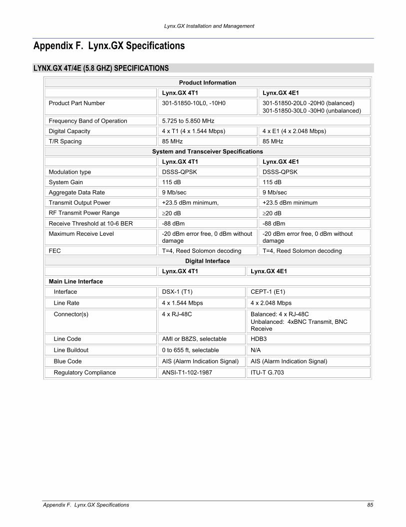
Appendix F. Lynx.GX Specifications
LYNX.GX 4T/4E (5.8 GHZ) SPECIFICATIONS Product Information
Lynx.GX 4T1 Lynx.GX 4E1 Product Part Number 301-51850-10L0, -10H0 301-51850-20L0 -20H0 (balanced)
301-51850-30L0 -30H0 (unbalanced) Frequency Band of Operation 5.725 to 5.850 MHz
Digital Capacity 4 x T1 (4 x 1.544 Mbps) 4 x E1 (4 x 2.048 Mbps)
T/R Spacing 85 MHz 85 MHz System and Transceiver Specifications
Lynx.GX 4T1 Lynx.GX 4E1 Modulation type DSSS-QPSK DSSS-QPSK
System Gain 115 dB 115 dB
Aggregate Data Rate 9 Mb/sec 9 Mb/sec
Transmit Output Power +23.5 dBm minimum, +23.5 dBm minimum RF Transmit Power Range ≥20 dB ≥20 dB
Receive Threshold at 10-6 BER -88 dBm -88 dBm Maximum Receive Level -20 dBm error free, 0 dBm without
damage -20 dBm error free, 0 dBm without damage
FEC T=4, Reed Solomon decoding T=4, Reed Solomon decoding Digital Interface
Lynx.GX 4T1 Lynx.GX 4E1 Main Line Interface Interface DSX-1 (T1) CEPT-1 (E1)
Line Rate 4 x 1.544 Mbps 4 x 2.048 Mbps
Connector(s) 4 x RJ-48C Balanced: 4 x RJ-48C Unbalanced: 4xBNC Transmit, BNC Receive
Line Code AMI or B8ZS, selectable HDB3
Line Buildout 0 to 655 ft, selectable N/A
Blue Code AIS (Alarm Indication Signal) AIS (Alarm Indication Signal)
Regulatory Compliance ANSI-T1-102-1987 ITU-T G.703
Appendix F. Lynx.GX Specifications 85

Lynx.GX Installation and Management
LYNX.GX 8T (ISM) SPECIFICATIONS
Product Information
Product Name Lynx.GX 8T1
Product Part Number 301-51145-10L0, -10H0
Frequency Band of Operation 5.725 to 5.850 MHz
Digital Capacity 8 x T1 (8 x 1.544 Mbps)
T/R Spacing 85 MHz
Emission Designator 13M4G7D
System and Transceiver Specifications
Frequency Range 5.725 – 5.850 GHz
Modulation type DSSS QPSK
System Gain 112 dB
Aggregate Data Rate 13.5 Mb/sec, full-duplex
Transmit Output Power ≥ +23.5 dBm minimum,at zero attenuation
RF Transmit Power Range 20 dB
Receive Threshold at 10-6 BER -86 dBm
Maximum Receive Level -20 dBm error free, 0 dBm without damage
FEC T=4, Reed Solomon decoding
Digital Interface
Main Line Interface
Interface DSX-1 (T1)
Line Rate 8 x 1.544 Mbps
Connector(s) 8 x RJ-48C
Line Code AMI or B8ZS, selectable for each input
Line Build-out 0 to 655 ft, selectable for each input
Blue Code AIS (Alarm Indication Signal, All Ones)
Regulatory Compliance ANSI-T1-102-1987
Appendix F. Lynx.GX Specifications 86

Lynx.GX Installation and Management
LYNX.GX 8E (ISM) SPECIFICATIONS
Product Information
Product Name Lynx.GX 8E1
Product Part Number 301-51145-20H0, -20L0
Frequency Band of Operation 5.725 to 5.850 MHz
Digital Capacity 16.384 Mbps (8 x E1)
T/R Spacing 85 MHz
Emission Designator 28M4G7D
System and Transceiver Specifications
Frequency Range 5.725 to 5.850 MHz
Modulation type DSSS QPSK
System Gain 110 dB
Aggregate Data Rate 27.5 Mb/sec
Transmit Output Power +23.5 dBm minimum, at zero attenuation
RF Transmit Power Range 20 dB
Receive Threshold at 10-6 BER -85 dBm
Maximum Receive Level -20 dBm error free, 0 dBm without damage
FEC T=4, Reed Solomon decoding
Digital Interface
Main Line Interface
Interface CEPT-1 (E1)
Line Rate 8 x 2.044 Mbps
Connector(s) 8 x RJ-45
Line Code HDB3
Blue Code AIS (Alarm Indication Signal)
Regulatory Compliance ITU-T G.703
Appendix F. Lynx.GX Specifications 87

Lynx.GX Installation and Management
LYNX.GX 16T SPECIFICATIONS
Product Information
Product Name Lynx.GX 16T1
Product Part Number 301-52290-10L0 (Low Band), -10H0 (High Band)
Frequency Band of Operation 5.725 to 5.850 MHz
Digital Capacity 16 x T1 (16 x 1.544 Mbps)
T/R Spacing 85 MHz
Emission Designator 28M1G7D
System and Transceiver Specifications
Modulation type DSSS QPSK
System Gain 109 dB
Aggregate Data Rate 27.5 Mb/sec, full-duplex
Transmit Output Power ≥ +23.5 dBm minimum, at zero attenuation
RF Transmit Power Control Range ≥ 20 dB
Receive Threshold at 10-6 BER -83 dBm
Maximum Receive Level -20 dBm error free, 0 dBm without damage
FEC T=4, Reed Solomon decoding
Primary Interface
Interface DSX-1 (T1)
Line Rate 16 x 1.544 Mbps
Connector(s) 16 x RJ-48C
Line Code AMI or B8ZS, selectable for each input
Line Build-out 0 to 655 ft, selectable for each input
Blue Code AIS (Alarm Indication Signal, All Ones)
Regulatory Compliance ANSI-T1-102-1987
Appendix F. Lynx.GX Specifications 88

Lynx.GX Installation and Management
DETAILED LYNX.GX SPECIFICATIONS
General System Parameters
Operating Frequency 5.8 GHz ISM band
Product Configuration Split box IDU + RF Unit (RFU with outdoor option)
Digital Capacity Up to 16 x T1 (16 x 1.544 Mbps)
Intermediate Frequency 749 MHz, 140 MHz (+/- 2 MHz)
Digital Interface DSX-1 for T1, CEPT-1 for E1
Error Floor <10-11
Latency (msec) 325 µsec ± 10% plus air latency (speed of light)
Error Correction FEC, Reed-Solomon Decoding
Security User-programmed 12 character Link ID (48 bits), imbedded and multiplexed into total digital signal
Regulatory Compliance FCC Part 15.247; IC RSS210
FCC ID / Industry Canada ID HZB –US5358-GX1 / 1856A-U5358GX1
Auxiliary Connections (IDU)
Orderwire (for DTMF Handset)
Connector 2-wire, 6-pin modular jack RJ-11
REN 1.0 B or less
DTMF Tones Within ± 1.5% of nominal frequency (+0 to 6 dB)
Ringing Voltage +48 AC, typical
Address 100, from 00 to 99
VF (Orderwire Bridge)
Connector 8-pin modular RJ-45 jack (4-wire); bridged to Orderwire RJ-11
Input Level and Output Level 0 dBm
Impedance 600 ohm balanced
Configuration Port
Connector DB-9 DTE (female, 9 pin D sub)
Protocol (serial) EIA-574 (8 bit data, No Parity, 1 Stop Bit)
Data Rate 9.6 kbps
Auxiliary Data Port
Connector 8-pin modular RJ-45 DCE
Protocol (serial) EIA-561 (8 bit Data, No Parity, 1 Stop Bit)
Data Rate 2.4 kbps, 4.8 kbps, 9.6 kbps, 19.2 kbps (selectable)
Alarms Port
Connector DB-9 (female, 9 pin D sub)
Form C Relay (NO, NC) Minor “Summary” Alarm, Major “Out-of-Service” Alarm
External Contact Relay Two, alarm caused by open or close condition set by user
Appendix F. Lynx.GX Specifications 89
Lynx.GX Installation and Management
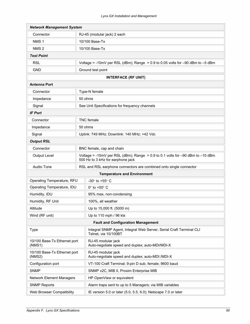
Network Management System
Connector RJ-45 (modular jack) 2 each
NMS 1 10/100 Base-Tx
NMS 2 10/100 Base-Tx
Test Point
RSL Voltage = -10mV per RSL (dBm); Range = 0.9 to 0.05 volts for –90 dBm to –5 dBm
GND Ground test point
INTERFACE (RF UNIT)
Antenna Port
Connector Type-N female
Impedance 50 ohms
Signal See Unit Specifications for frequency channels
IF Port
Connector TNC female
Impedance 50 ohms
Signal Uplink: 749 MHz; Downlink: 140 MHz; +42 Vdc
Output RSL
Connector BNC female, cap and chain
Output Level Voltage = -10mV per RSL (dBm); Range = 0.9 to 0.1 volts for –90 dBm to –10 dBm 500 Hz to 3 kHz for earphone jack
Audio Tone RSL and RSL earphone connectors are combined onto single connector
Temperature and Environment
Operating Temperature, RFU -30° to +55° C Operating Temperature, IDU 0° to +50° C
Humidity, IDU 95% max, non-condensing
Humidity, RF Unit 100%, all weather
Altitude Up to 15,000 ft. (5000 m)
Wind (RF unit) Up to 110 mph / 96 kts
Fault and Configuration Management
Type Integral SNMP Agent, Integral Web Server, Serial Craft Terminal CLI Telnet, via 10/100BT
10/100 Base-Tx Ethernet port (NMS1)
RJ-45 modular jack Auto-negotiate speed and duplex; auto-MDI/MDI-X
10/100 Base-Tx Ethernet port (NMS2)
RJ-45 modular jack Auto-negotiate speed and duplex; auto-MDI./MDI-X
Configuration port VT-100 Craft Terminal; 9-pin D sub, female; 9600 baud
SNMP SNMP v2C, MIB II, Proxim Enterprise MIB
Network Element Managers HP OpenView or equivalent
SNMP Reports Alarm traps sent to up to 5 Managers; via MIB variables
Web Browser Compatibility IE version 5.0 or later (5.0, 5.5, 6.0); Netscape 7.0 or later
Appendix F. Lynx.GX Specifications 90

Lynx.GX Installation and Management
User Access Security Two level password protection
Performance Management ES, SES, BER, LOS; near and far end
Alarm Log Up to 20,000 entries
Software Updates Download via HTTP over Ethernet
Configuration Management Local end or remote end using internal PPP, via IP address
Advanced features Spectrum Analyzer – 25 (2 MHz) display points; RSL Time charting – 5 sample rate selections; downloadable Integral NMS router
Power Requirements
IDU VDC nominal input voltage -48 Vdc or +24 Vdc
IDU DC Input Voltage Range -20 to –60 Vdc or +20 to +60 Vdc
Power Consumption Per Terminal < 70 watts
Power Consumption IDU: < 40 watts; RF Unit: <30 watts
AC Adapter (external) for IDU 130 watts; 50/60 Hz, 110/220 VAC; -48 Vdc, 2.7A
DC Power Connector (IDU) 3-pin barrier strip type, plug-in (+, Gnd, -)
Connector (IDU to RF Unit) TNC female
RF Unit voltage level +42 volts DC
Power delivery to RF Unit DC voltage over coax cable from IDU
Mechanical
IDU Size (w x h x d) Weight
17.2 x 1.72 x 10.9 inch (1RU) [43.6 x 4.4 x 27.6 cm] 6.5 lbs / 2.9 kg
RF Unit Size (w x h x d) Weight
14.1 x 1.72 x 10.9 inch (1RU) [35.8 x 4.4 x 27.6 cm] 12.0 lbs / 5.4 kg
Mounting IDU: EIA rack mount 19-inch rack mount; 23-inch extenders in kit RF Unit: EIA rack mount 19-inch rack mount; 23-inch extenders in kit Pole-mountable, 1.5 to 3 inch diameter pole using optional outdoor mounting plate
Cooling IDU: 3 each DC fans RF Unit: Built-in Heatsink, convection cooled in proper mounting configuration
CABLE SPECIFICATIONS
RF Cable to antenna
Cable type Low-loss coaxial: ½” foam, equivalent or better
Cable connector Type-N male
Impedance 50 ohm
IDU-RF Unit interconnection
Cable Type LMR-240 or equivalent for <100 meters LMR-400 or equivalent for <300 meters
Cable Connector TNC male
Impedance 50 ohm
DC power +42 VDC
Appendix F. Lynx.GX Specifications 91

Lynx.GX Installation and Management
IDU Controls
Far End Pushbutton Yes
NMS Connector LEDs
NMS 1 Right LED = Link: Green = Link On; Off = Link Off Left LED = Duplex: Green = Full; Flashing=Half w/collisions; Off = Half Duplex
NMS 2 Right LED = Link: Green = Link On; Off = Link Off Left LED = Duplex: Green = Full; Flashing=Half w/collisions; Off = Half Duplex
Appendix F. Lynx.GX Specifications 92

Lynx.GX Installation and Management
Appendix G. Troubleshooting This chapter provides information about:
Changing Frequency Plans Counteracting and Evaluating Interference Troubleshooting data stream errors and interference Troubleshooting alarms Measuring radio function Troubleshooting radio management tools Repair policy
CHANGING FREQUENCY PLANS
The radio frequency selections are listed in “Channel Plans” on page 70. The near-end radio and the far-end radio must correspond, for example, A1 and A2. All 1 frequency plans can be selected, when available, from the radio model with the low-side RF unit, or the “ –xxL0” model. All 2 frequency plans can be selected, when available, from the radio models with the high-side RF unit (the “–xxH0” model).
The frequency plans are configured in the Sys Cfg tab of the Web Interface.
COUNTERACTING AND EVALUATING INTERFERENCE
The recommended interference countermeasures available are:
Short paths Narrow beam antennas (high gain) Frequency channel selection and orientation Antenna Polarization Transmit Power Equipment/Antenna Location Use of a Spectrum Analyzer to evaluate potential interference
Short Paths
The single most effective countermeasure against interference is to maintain a “short path” length. This can be achieved by dividing long paths into multiple small paths by cascading hops. Intermediate repeaters can be formed using back-to-back terminals and transmit output power reduced, if required.
By definition, “short path” is defined as a path where fades are extremely rare and signal levels vary by no more than ±3 dB during fades. This distance varies with the RF frequency. Typically a “short path” is defined as any path length shorter than 5 miles at 5.8 GHz.
Appendix G. Troubleshooting 93
Lynx.GX Installation and Management
Narrow Beam Antennas (High Gain)
This is the next most effective countermeasure. Narrow-beam antennas ensure that the transmitted power is sent in a single direction; this minimizes the possibility of causing interference inadvertently to other users. Narrow beam antennas also reject off-azimuth signals being received from potential sources of interference and have high gain, which boosts desired receive levels and improves the carrier-to-interference signal level.
When selecting narrow beam antennas, it is helpful to know that larger antennas generally out-perform smaller antennas. Another important antenna specification is the front-to-back ratio, which ensures rejection of unwanted signals from azimuth angles behind the antenna. High performance antennas with improved sidelobe attenuation are also available.
Frequency Selection
You often can overcome interference by exchanging frequencies of both ends of the radio link (for example, change your A1 terminal to an A2 and change the other end from an A2 to an A1). For the GX series, this requires swapping of the RF Unit from end to end. Also, changing channel plans (for example, from A to B) can be very effective, provided multiple channel plans are available.
See “Channel Plans” on page 70 for frequency selections. The near-end radio and the far-end radio must be corresponding (such as A1 / A2).
Antenna Polarization
Cross-polarized antennas can provide approximately 20 to 30 dB discrimination of unwanted signals. The actual discrimination depends upon the antenna design and any rotation of polarization along the path (for example, due to reflections). Substantial discrimination only exists between two orthogonal polarizations:
Vertical versus horizontal Left-hand circular versus right-hand circular
There is only 3 dB discrimination between circular and linear (vertical or horizontal) polarization.
If changing polarization to minimize interference, the antenna polarization must be changed at both ends of the link.
Transmit Power
The maximum level into the receiver is -20 dBm. Errors can occur in the receive data stream above this level. You should reduce transmit output power on very short paths to avoid overload.
Equipment/Antenna Location
Interference is occasionally caused by the radio equipment or the antenna being too close to another similar transmitter. Moving the radio equipment, the antennas, or the interfering equipment can reduce or eliminate interference.
Interference countermeasures rely to some extent on the measurement of the received interference level and frequency. Before turning up a new link, use a spectrum analyzer (either built-in or external) to monitor the spectrum at each end to check for possible interfering signals. For more details, see the section that follows.
Appendix G. Troubleshooting 94
Lynx.GX Installation and Management
Use of a Spectrum Analyzer to Evaluate Potential Interference
Connecting to the antenna and using “peak hold” on a spectrum analyzer, the spectrum across the receive frequency range of the radio can be swept and any signals being received at levels above the radio's specified threshold identified.
If potential interfering signals are found, you can change the frequency plan to avoid a receive channel that may contain significant interference (see “Changing Frequency Plans on page 93. For example, you can reduce interference by moving or swapping terminals. Signals outside the receiver frequency range can be generally ignored: they almost always do not cause interference.
When using an external spectrum analyzer for determining the presence of interference, use very narrow resolution bandwidth settings to detect signals down to the unit’s threshold (approximately -80 dBm, depending upon the type of radio). Use a directional antenna in combination with the spectrum analyzer and determine not only the frequency, but also the primary direction and the dominant polarization of interference sources. Once the frequency, direction, and dominant polarization of interference is known, proper planning for your radio system’s channel plan, polarization, and antenna placement can be optimized.
TROUBLESHOOTING ALARMS
Use these troubleshooting guidelines when you receive:
Data Stream Errors RF Link Alarms RF Unit, Cable, IDU Alarms Far End Alarms
Data Stream Errors
When the radio is in service, errors in the user data may occur. This is usually known to the operator either by faulty data indications of downstream equipment or by external bit error rate testing. It is possible that no alarms appear on the front panel during normal operations, even when there are errors present in the data stream.
Some errors do not result in an alarm (such as bipolar violations, improperly terminated connections, or certain incorrect settings), but are exhibited on downstream data processing equipment or during a BER test.
In other cases, there may be data errors due to atmospheric conditions (fading), interference, or other reasons, but not at a high enough error level to be indicated with the BER alarm LED. In the case of these types of errors, the following information can be helpful to troubleshoot the radio link.
Indications
During external BER test, test equipment indicates errors Downstream equipment (multiplexer, channel bank, codec, router, and so on) indicates errors
Possible Causes
Path fading due to atmospheric conditions Poor transmission line connections Antenna problems, misalignment or path clearance Received signal level (RSL) is too strong Far-end radio transmitter circuitry is faulty Near-end radio receiver circuitry is faulty Interference
Appendix G. Troubleshooting 95

Lynx.GX Installation and Management
Recommended Actions
Check and Verify data interface wiring Follow the troubleshooting instructions described in “IDU Fail Alarms.”
RF Link Alarms
This LED indicates that the demodulator function is not synchronizing with the intended received signal.
Possible Causes
Severe path fading due to atmospheric conditions, usually accompanied by a low RSL voltage reading Poor transmission line connections, usually, but not always, accompanied by low RSL voltage reading Antenna problems, misalignment, or path clearance, usually accompanied by low RSL voltage reading Improper radio settings (such as frequency channel) Received signal level (RSL) is too strong Interference Far-end radio transmitter circuitry is faulty Near-end radio receiver circuitry is faulty Link security ID mismatch between the radios (flashing)
Recommended Actions
Check the following at each end of the link:
Verify that radios are opposite channel plans on each end (for example, one is A1 and other is A2).
Verify that all connections between radios and antennas are secure and all devices between radios and antennas are rated for the radio frequency band (5.8 GHz). View RF Link alarm while flexing transmission lines near all connectors to test for poor connector terminations.
Measure RSL by placing a voltmeter across RSL and GND test points and:
Comparing this to the RSL that was expected using path calculations (see “Calculating RSL and Link Budget” on page 51) and the RSL that was achieved during installation (if RSL was once sufficient).
Pressing and holding the DISPLAY FAR END button and measuring the far-end RSL (while continuing to hold the button).
Comparing this RSL to the expected RSL from the link budget calculations.
Excessive Loss
If RSL from both ends of the radio are approximately the same as each other, but lower than anticipated for this installation, then the likely cause of the BER alarm is excessive losses between the radios. Excessive loss problems could include the transmission line at either end, all adapters, connectors, the antennas, the antenna alignment, as well as the path itself (any obstructions or clearance problems).
Verify antenna alignment, line-of-sight, and path clearance; if this does not improve RSL, check all devices between the radios and their antennas at both ends. Make sure all transmission lines, connectors, and any other devices are properly rated for operation at the radio's frequency (5.8 GHz).
Appendix G. Troubleshooting 96

Lynx.GX Installation and Management
Power Adjustment
If only one end has low RSL, this could be caused by low transmit output power from the opposite end radio. Verify that the transmitter output power of the radio opposite to the low RSL receiver has been set in accordance to path calculations or EIRP restrictions (where applicable).
WARNING! Power adjustment must be performed by professional installation personnel only.
Tx Power can be viewed or adjusted from the Sys Cfg web page.
If an RF power meter is available, you can connect it to the RF output of the RF Unit for precision measurement. This test also verifies that the radio transmitter is working properly. This is highly recommended if RSL is low in only one direction. If one terminal has high RSL, this could be caused by interference.
Short Path or Interference
To verify the possible presence of interference, remove DC power to the unit opposite the one that is reading high RSL or experiencing errors. Once power is removed, measure RSL on the remaining radio. If RSL voltage is lower than its threshold, it is unlikely that an interfering signal is present. If an RSL measurement is made above threshold, then the presence of interference is likely.
If interference is suspected, the most effective potential remedy is to swap frequency channels on both sides of the link. (see “Changing Frequency Plans” on page 93). Swap RF Units at both ends of the link so they are the opposite of their original installation. After both ends are moved, reconnect the radios and determine whether the BER alarm is still active. If so, you can select other frequency channels or try other interference counter-measures, as discussed in “Counteracting and Evaluating Interference” on page 93.
Possible Radio Failure
If all path related and data input problems have been pursued and the BER alarm is still active, the problem could be related to a radio failure. Although radio failure typically is indicated by more severe alarm conditions, it is possible that one of the radios may be out of specification, and this could be the cause of the BER alarm. A back-to-back test verifies proper radio operation. See “Test Radios Back-to-Back” on page 11 for more information. A threshold test on both radios, along with a test to verify proper RF output power, would be beneficial.
Perform a back-to-back test before returning any radio terminal to the factory for repair. A back-to-back test verifies radio operation.
If the radios pass their back-to-back testing successfully, the problem is likely with the path, with the connections between the radio and the antenna, or interference. Before you reinstall the radios, be sure to set the output power to the appropriate level for the installation.
Appendix G. Troubleshooting 97

Lynx.GX Installation and Management
RF Unit, Cable, and IDU Alarms
These LEDs indicate a known problem with the radio hardware.
Possible Causes
RF Unit hardware failure, such as amplifier or pre-amp circuits IF cable shorted IDU hardware failure
Recommended Actions
1. Remove power from the unit.
2. Check to make sure power supply voltages are within specification.
3. Reapply power to the unit, even if the voltages were within specification.
4. Verify that RF UNIT cable is assembled and connected correctly
º If the alarm clears, place the radio back into service.
º If the alarm does not clear, perform a back-to-back test to verify radio operation.
º If the alarm is still active in a back-to-back test, return the unit in alarm to the factory for repair.
Far End Alarms
This LED indicates that there is an alarm condition present on the far-end radio. When the DISPLAY FAR END button is pressed (and held), the status LEDs indicates the alarm conditions of the far-end radio.
Possible Causes
One or more alarm conditions exist on the far-end radio.
Recommended Actions
Press and hold the DISPLAY FAR END button and observe the LED status. Follow the troubleshooting instructions provided in “RF Link Alarms” and “RF Unit, Cable, and IDU Alarms.”
TROUBLESHOOTING THE WEB INTERFACE MANAGEMENT TOOL Problem
Slow Web Interface Unable to logon to the Web Interface
Solution
Check the Ethernet duplex settings of the PC or switch connected to it. Set the PC or switch to auto-negotiate, or half duplex if auto-negotiate is not available. The NMS ports on the radio are auto-sensing for speed and duplex.
Check that the IP address of the PC is in the same subnet as the locally connected radio, that is, 10.0.0.0.
Check the CAT5 cable by using an Ethernet cable tester or using the same cable with another known good device.
Appendix G. Troubleshooting 98

Lynx.GX Installation and Management
REPAIR POLICY The radio terminal includes comprehensive alarm indicators designed to diagnose potential faults. Should a fault occur, it often can be resolved by operator adjustment. If a fault occurs that cannot be resolved by operator adjustment and that has been confirmed by back-to-back testing, the equipment should be returned to Proxim for repair.
The GX radios are complex systems not designed for user repair. Do not remove the cover or open any part of the terminal. Contact [email protected] for assistance in determining possible problems and troubleshooting.
Contact the factory in advance of returning the product. You will be assigned a Return Material Authorization (RMA) number that authorizes your return. Units sent to the factory without an RMA number may delay the repair process. Be sure to include the following information:
RMA number Description of the problem Your name and telephone number Return shipping address Urgency of repair
See the published Warranty policy for repair policy details.
Radios should be packaged in their original packing boxes for shipment. Whenever possible, Proxim Corporation can provide an empty box shipment to facilitate proper packaging. Regardless, proper and adequate packaging must be used for shipments to protect the units from damage. Proxim Corporation cannot be held responsible for any repairs due to inadequately packed materials.
Damage caused by improper packing can result in higher repair costs and delays. See “Warranty” for explicit product warranty information.
Proxim Corporation provides 24-hour telephone technical support with purchased service plans. We do, however, encourage you to troubleshoot your radio and link according to the troubleshooting methods provided in this document.
Appendix G. Troubleshooting 99

Lynx.GX Installation and Management
Technical Support If you are having a problem using a Lynx.GX product and cannot resolve it with the information in “Troubleshooting” on page 93, gather the following information and contact Proxim Technical Support:
What kind of network are you using? What were you doing when the error occurred? What error message did you see? Can you reproduce the problem?
Be sure to:
Note the serial number of the product before installation. Keep this information in a safe place. The serial number is required to obtain support and can be found only on the back of the unit.
Obtain an RMA number before sending any equipment to Proxim for repair.
Access Knowledgebase: [email protected] Ask your wireless WAN question and get an express response:
E-mail Technical Support: [email protected]
Web Technical Support: http://www.proxim.com/support
Call Technical Support: Toll Free +1-866-674-6626 or +1-408-542-5390 Hours: 6:00 a.m. to 5:00 p.m. M-F Pacific Time
ENHANCED WARRANTY PACKAGES
Proxim’s ServPak program delivers premium support services that complement your Lynx.GX standard warranty. Available services include, warranty extension, 24x7x365 technical phone support and priority response, and next day priority hardware replacement. For more information, contact Proxim or your Proxim authorized reseller.
Technical Support 100
Lynx.GX Installation and Management
Warranty 1. PROXIM CORPORATION TWO-YEAR LIMITED EQUIPMENT WARRANTY
1.1 For the applicable Warranty Period (as defined in Paragraph 1.2 below) Proxim warrants that the hardware manufactured by Proxim and initially purchased or leased from one of Proxim's authorized resellers or distributors by the original end-user ("you") for your personal use and not for resale (the "Equipment") (a) substantially conforms to the specifications contained in the most recent version of the manual for the model of the Equipment purchased or leased by you (the "Equipment Specifications") and (b) is free from defects in materials and workmanship. This Limited Warranty only applies to the Equipment and its preloaded firmware. This Limited Warranty does not apply to any software (or its associated documentation), whether preloaded with the Equipment, installed subsequently or otherwise ("Software"), nor does it apply to any firmware revision that is not originally preloaded on the Equipment at the time the Equipment is purchased or leased. The Software is licensed to you pursuant to the software license agreement that accompanied the Software and is subject to the terms, including the limited warranty and limitation of liability, contained in that license agreement. Proxim has no obligation to repair or replace Software under this Limited Warranty.
1.2 This Limited Warranty shall start on the date that the Equipment is first shipped to you (the "Shipping Date") and shall end two (2) years after the Shipping Date ("Warranty Period").
1.3 Nothing in this Limited Warranty affects any statutory rights of consumers that cannot be waived or limited by contract.
2. LIMITED WARRANTY EXCLUSIONS AND LIMITATIONS.
2.1 The Limited Warranty covers customary and intended usage only.
2.2 Proxim does not warrant, and is not responsible for damage, defects or failures caused by any of the following:
(a) Any part of the Equipment having been modified, adapted, repaired, or improperly installed, operated, maintained, stored, transported or relocated by any person other than Proxim personnel or a Proxim authorized service agent;
(b) External causes, including electrical stress or lightning, interference caused by other radios or other sources, unsuitable physical or operating environment and use in conjunction with incompatible equipment or accessories;
(c) Cosmetic damage, including all damage to the surface of the Equipment;
(d) Acts of God, fires, floods, wars, terrorist acts, sabotage, civil unrest, labor disputes or similar events, actions or hazards; and
(e) Accidents, negligence, neglect, mishandling, abuse or misuse, other than by Proxim personnel or a Proxim authorized service agent.
2.3 The Limited Warranty does not apply to the following parts of the Equipment, which are not manufactured by Proxim, but which may be otherwise covered by an original manufacturer's warranty:
(a) antenna systems, including coaxial cable, wave guide, connectors, flex sections, mounts, and other parts of the antenna system and installation materials;
(b) rack mounted equipment, which is not manufactured by Proxim but which may be assembled, wired and tested at Proxim's factory or supplied as part of a system, including orderwire items, channel banks, multiplexers, fuse/alarm panels and remote alarm items; and
(c) all equipment which is not included in Proxim's specifications.
2.4 Unless otherwise specified, equipment not manufactured by Proxim is provided "AS IS" AND WITHOUT WARRANTIES OF ANY KIND. Please refer to the original manufacturer's warranty, if any.
2.5 Any technical or other support provided for the Equipment by Proxim, such as telephone assistance or assistance regarding the installation, is provided "AS IS" AND WITHOUT WARRANTIES OF ANY KIND.
3. REPLACEMENT, REPAIR AND RETURN PROCESSES.
3.1 To request service under the Limited Warranty:
(a) You must, within the applicable Warranty Period, promptly notify Proxim of the problem with the Equipment, provide the serial number of the Equipment, and provide your contact information during business hours, by contacting Proxim by telephone at 408-542-5390 during the business hours of 8:00 a.m. to 5:00 p.m., Pacific Time, Monday through Friday, excluding holidays, or by e-mail at [email protected] or by mail to Support, Proxim Corporation, 935 Stewart Drive, Sunnyvale, CA 94085, USA, This notice is effective when received by Proxim during the business hours referenced above.
(b) Proxim shall, at its sole option, either resolve the problem over the telephone or provide you with a returned materials authorization number ("RMA Number") and the address of the location to which you may ship the Equipment at issue.
(c) If the problem is not resolved over the telephone, and Proxim gives you an RMA Number, you must, within ten (10) business days of your receipt of an RMA Number if you are located within the borders of the United States and within thirty (30) days of your receipt of an RMA Number if you are located beyond the borders of the United States, at your cost, ship the Equipment to the location specified by Proxim. The Equipment must be shipped in its original or equivalent packaging. You must also attach a label to each item of Equipment you are returning, which must include the following information: the RMA Number, a description of the problem, your return address and a telephone number where you can be reached during business hours. You must also include with the Equipment a dated proof of original purchase. YOU ARE RESPONSIBLE FOR ALL EQUIPMENT UNTIL PROXIM RECEIVES IT, AND YOU ARE RESPONSIBLE FOR ALL SHIPPING, HANDLING AND INSURANCE CHARGES, WHICH MUST BE PREPAID.
Warranty 101

Lynx.GX Installation and Management
(d) Proxim is not responsible for Equipment received without an RMA Number and may reject the return of such Equipment. PROXIM IS ALSO NOT RESPONSIBLE FOR ANY OF YOUR CONFIDENTIAL, PROPRIETARY OR OTHER INFORMATION OR DATA CONTAINED IN EQUIPMENT YOU RETURN TO PROXIM. You should remove any such information or data from the Equipment prior to making any return to Proxim.
(e) The replacement or repair of Equipment in locations outside of the United States may vary depending on your location.
(f) FAILURE TO FOLLOW THE PROCEDURES FOR RETURNS LISTED ABOVE MAY VOID THE LIMITED WARRANTY.
3.2 If the Equipment does not function as warranted, as determined by Proxim in its sole discretion, Proxim shall either repair or replace the returned Equipment at its sole option.
(a) The replacement Equipment or parts may be new or refurbished. All parts removed from repaired Equipment and all returned Equipment that is replaced by Proxim become the property of Proxim.
(b) Proxim shall, at its cost (which shall not include international customs, freight forwarding, or associated fees) ship the repaired or replacement Equipment to any destination, by carrier and method of delivery chosen by Proxim, in its sole discretion. Proxim will not pay, and you will be solely responsible for, any international customs, freight forwarding, or other associated fees related to such shipment. If you request some other form of conveyance, such as express shipping, you must pay the cost of return shipment.
3.3 Equipment which is repaired or replaced by Proxim under this Limited Warranty shall be covered under all of the provisions of this Limited Warranty for the remainder of the applicable Warranty Period or ninety (90) days from the date of shipment of the repaired or replacement Equipment, whichever period is longer.
4. LIMITATIONS OF RIGHTS AND DISCLAIMER OF OTHER WARRANTIES
4.1 THE LIMITED WARRANTY CONTAINS LlMITATIONS ON YOUR RIGHTS AND REMEDIES AGAINST PROXIM. YOU ACKNOWLEDGE HAVING READ, UNDERSTOOD AND AGREED TO THOSE LIMITATIONS.
4.2 Proxim does not warrant that the functions contained in the Equipment will meet your requirements or that any Equipment's operation will be uninterrupted or error free. REPAIR OR REPLACEMENT OF THE EQUIPMENT AS PROVIDED HEREIN IS THE EXCLUSIVE REMEDY AVAILABLE TO YOU, AND IS PROVIDED IN LIEU OF ALL OTHER WARRANTIES, WHETHER ORAL OR WRITTEN, EXPRESS OR IMPLIED, INCLUDING, BUT NOT LIMITED TO, THE IMPLIED WARRANTIES OF MERCHANTABILITY AND FITNESS FOR A PARTICULAR PURPOSE AND NONINFRINGEMENT OF THIRD PARTY RIGHTS. ALL OTHER WARRANTIES ARE EXCLUDED TO THE FULLEST EXTENT PERMITTED BY LAW AND EXCEPT FOR THE LIMITED WARRANTY PROVIDED HEREIN, THE EQUIPMENT IS PROVIDED "AS IS". No dealer, agent, or employee is authorized to make any modification, extension, or addition to the Limited Warranty.
5. LIMITATION OF LIABILITY
PROXIM SHALL NOT BE LIABLE TO YOU FOR INDIRECT, SPECIAL, PUNITIVE, INCIDENTAL OR CONSEQUENTIAL DAMAGES (INCLUDING, BUT NOT LIMITED TO, LOST PROFITS) OF ANY KIND SUSTAINED OR INCURRED IN CONNECTION WITH, OR RELATED TO, THE EQUIPMENT OR YOUR USE OF THE EQUIPMENT REGARDLESS OF THE FORM OF ACTION OR NATURE OF THE CLAIM (INCLUDING, BUT NOT LIMITED TO, BREACH OF WARRANTY, BREACH OF CONTRACT, TORT, NEGLIGENCE OR STRICT LIABILITY) AND WHETHER OR NOT SUCH DAMAGES ARE FORESEEABLE, AND EVEN IF PROXIM HAS BEEN ADVISED OF THE POSSIBILITY OF SUCH LOSS. IN NO CASE WILL PROXIM BE LIABLE FOR ANY REPRESENTATION OR WARRANTY MADE BY ANY PARTY OTHER THAN PROXIM. PROXIM'S TOTAL LIABILITY TO YOU SHALL NOT EXCEED THE AMOUNT PAID BY YOU FOR THE EQUIPMENT AT ISSUE. This limitation of liability also applies to Proxim's authorized resellers and distributors and it is the maximum amount for which Proxim and the reseller or distributor who sold you the Equipment are collectively responsible.
6. DISCLAIMERS
This Limited Warranty gives you specific legal rights, and you may also have other rights that vary from jurisdiction to jurisdiction. Some jurisdictions do not allow the exclusion or limitation of incidental or consequential damages, may not allow limitations on how long an implied warranty lasts, and may not allow provisions that permit a warranty to be voided. Consequently, such limitations and exclusions may not apply to you. In the event an implied warranty cannot be excluded under the law of the applicable jurisdiction, it is limited in duration to the applicable Warranty Period.
7. MISCELLANEOUS
7.1 Transfer. You may not transfer or assign this Limited Warranty. Any transfers or assignments made in violation of this Paragraph shall be void.
7.2 Governing Law. The Limited Warranty shall be governed by the laws of the State of California, without reference to its conflicts of laws provisions. The United Nations Convention on the International Sale of Goods shall not apply to this Limited Warranty.
7.3 Arbitration/Dispute Resolution. Any dispute, controversy or claim arising out of or in connection with the Equipment shall be finally resolved by arbitration under the International Arbitration Rules of the American Arbitration Association. The place of arbitration shall be Sunnyvale, California. The number of arbitrators shall be one. The language of arbitration shall be English.
7.4 Indemnification. You shall indemnify and hold harmless Proxim (including its directors, officers, employers and agents) against any and all claims (including all expenses and reasonable attorneys' fees) arising from or relating to the operation of the Equipment due to, in whole or in part, your (including your agents' or employees') negligence, gross negligence or misconduct.
Warranty 102

Lynx.GX Installation and Maintenance BETA VERSION
Acronyms / Glossary 10 Base-T/F This designation is an Institute of Electrical and Electronics Engineers (IEEE) shorthand identifier. The "10" in the media type designation refers to the transmission speed of 10 Mbps. The "Base" refers to baseband signaling, which means that only Ethernet signals are carried on the medium. The "T" represents twisted-pair; the "F" represents fiber optic cable.
bandwidth The width of a band of electromagnetic frequencies. Used to mean (1) how fast data flows on a given transmission path, and (2), somewhat more technically, the width of the range of frequencies that an electronic signal occupies on a given transmission medium. Any digital or analog signal has a bandwidth.
100 Base-TX/FX The "100" in the media type designation refers to the transmission speed of 100 Mbps. The "Base" refers to baseband signaling, which means that only Ethernet signals are carried on the medium. The "TX" represents two pairs of data grade twisted-pair wire; the “FX” represents a two-strand optical fiber cable.
baseband Any frequency band on which information is superimposed, whether or not the band is multiplexed and information is sent on sub-bands. The frequency band is not shifted to some other frequency band but remains at its original place in the electromagnetic spectrum.
baud Baud was the prevalent measure for data transmission speed until replaced by a more accurate term, bps (bits per second).
AC Alternating Current
Alternating current In electricity, alternating current (AC) occurs when charge carriers in a conductor or semiconductor periodically reverse their direction of movement.
beamwidth, half power In a plane containing the direction of the maximum lobe of the antenna pattern, the angle between the two directions in which the radiated power is one-half the maximum value of the lobe.
BER Bit Error Rate. The bit error rate (BER) is the percentage of bits that have errors relative to the total number of bits received in a transmission, usually expressed as ten to a negative power.
amp Ampere. An ampere is a unit of measure of the rate of electron flow or current in an electrical conductor. One ampere of current represents one coulomb of electrical charge (6.24 x 10¹⁸ charge carriers) moving past a specific point in one second.
BNC connector Developed in the late 1940’s as a miniature version of the Type C connector, BNC stands for Bayonet Neill Concelman and is named after Amphenol engineer Carl Concelman. The BNC product line is a miniature quick connect/disconnect RF connector.
amplifier An electronic device that increases the voltage, current, or power of a signal.
analog An analog signal is one in which a base carrier’s alternating current frequency is modified in some way, such as by amplifying the strength of the signal or varying the frequency, in order to add information to the signal.
broadband In general, broadband refers to telecommunication in which a wide band of frequencies is available to transmit information. Because a wide band of frequencies is available, information can be multiplexed and sent on many different frequencies or channels within the band concurrently, allowing more information to be transmitted in a given amount of time (much as more lanes on a highway allow more cars to travel on it at the same time).
antenna A device used for radiating or receiving electromagnetic energy.
attenuate To lessen the strength of.
CLI Command Line Interface.
AUX Auxiliary
coax Coaxial cable. A cable comprised of a center conductor, surrounded by an insulating core, with a braided or solid shield. Conductive shield surrounds the core with outside insulation.
azimuth Azimuth and elevation are angles used to define the apparent position of an object in the sky, relative to a specific observation point. The observer is usually (but not necessarily) located on the earth's surface. The azimuth (az) angle is the compass bearing, relative to true (geographic) north, of a point on the horizon directly beneath an observed object. As seen from above the observer, compass bearings are measured clockwise in degrees from north. Azimuth angles can thus range from 0 degrees (north) through 90 (east), 180 (south), 270 (west), and up to 360 (north again). The elevation (el) angle, also called the altitude, of an observed object is determined by first finding the compass bearing on the horizon relative to true north, and then measuring the angle between that point and the object, from the reference frame of the observer.
codec The term codec is also an acronym that stands for "compression/decompression." A codec is an algorithm or specialized computer program that reduces the number of bytes consumed by large files and programs.
dB Decibel. In electronics and communications, the decibel (abbreviated as dB, and also as db and DB) is a logarithmic expression of the ratio between two signal power, voltage, or current levels.
dBi Used to define the gain of an antenna system relative to an isotropic radiator at radio frequencies. The symbol is an abbreviation for "decibels relative to isotropic."
Elevation angles for objects above the horizon range from 0 (on the horizon) up to 90 degrees (at the zenith).
back-to-back testing A simple way to verify that the radios are fully operational before they are installed.
Acronyms / Glossary 103

Lynx.GX Installation and Management
dBm Used to define signal strength in wires and cables at radio and audio frequencies. The symbol is an abbreviation for "decibels relative to one milliwatt," where one milliwatt (1 mW) equals 1/1000 of a watt (0.001 W or 10-3 W).
elevation See azimuth.
ERP Effective Radiated Power. The product of the power supplied to the antenna and its gain relative to a half-wave dipole in a given direction. DC
Direct Current fade margin Difference between the actual received signal level and the radio’s threshold.
DCE Distributed Computing Environment. An industry-standard software technology for setting up and managing computing and data exchange in a system of distributed computers. FCC
Federal Communications Commission. demux De-multiplexer FEC Forward Error Correction.
Forward Error Correction is a coding scheme used to improve the performance of digital signal transmission. It utilizes a mechanism for correcting bits that may otherwise be received incorrectly.
diffraction The apparent bending of light waves around obstacles in its path.
digital Electronic technology that generates, stores, and processes data in terms of two states: positive and non-positive.
Fresnel Zone Parabolic areas around the visual line-of-sight that define the even and odd reflection points where multipath signals will either be constructive or destructive to the radio waves. Based on the frequency of the signal, the Fresnel zones help define the proper antenna heights to establish ideal path clearance for optimum signal reception.
diplexer Combines signals so only one coaxial wire needs to be run.
dipole antenna A straight electrical conductor measuring ½ wavelength from end to end and connected at the center to a radio-frequency feed line.
FTP File Transfer Protocol. A standard Internet protocol; the simplest way to exchange files between computers on the Internet.
direct current DC (Direct current) is the unidirectional flow or movement of electric charge carriers, usually electron.
gain A ratio, expressed in decibels, of the action of an antenna increasing the strength of a signal.
DTE Data Terminal Equipment. In computer data transmission, the RS-232C interface that a computer uses to exchange data with a modem or other serial device.
GPS Global Positioning System. Lets you ascertain your location anywhere on earth.
HD High Density. duplex
Duplex communication means that both ends of the communication can send and receive signals. Full duplex communication is where this happens simultaneously. Half duplex is also bidirectional communication, but signals only flow in one direction at a time.
heatsink A device that is attached to a microprocessor chip to keep it from overheating by absorbing its heat and dissipating it into the air. Most heatsinks are aluminum and have "fins" that extend from the base. DVM
Digital Volt Meter. hertz The unit for expressing frequency, ( f ). One hertz equals one cycle per second. E1
E1 (or E-1) is a European digital transmission format devised by the ITU-TS and given the name by the Conference of European Postal and Telecommunication Administration (CEPT). It is the equivalent of the North American T-carrier system format.
HTTP Hypertext Transfer Protocol. The set of rules for exchanging files (text, graphic images, sound, video, and other multimedia files) on the World Wide Web.
The E1 signal format carries data at a rate of 2.048 million bits per second and can carry 32 channels of 64 Kbps each. E1 carries at a somewhat higher data rate than T-1 (which carries 1.544 million bits per second) because, unlike T-1, it does not do bit-robbing and all eight bits per channel are used to code the signal. E1 and T-1 can be interconnected for international use.
HyperTerminal A program that you can use to connect to other computers, Internet telnet sites, bulletin board systems (BBSs), online services, and host computers, using either your modem or your network card.
EIA Electronic Industries Association. Comprises individual organizations that together have agreed on certain data transmission standards such as EIA/TIA-232 (formerly known as RS-232).
IDU Indoor Unit.
IF Intermediate Frequency.
IP Internet Protocol. The method or protocol by which data is sent from one computer to another on the Internet. Each computer (known as a host) on the Internet has at least one IP address that uniquely identifies it from all other computers on the Internet.
EIRP Effective Isotropic Radiated Power. The product of the power supplied to the antenna and the antenna gain in a given direction relative to an isotropic antenna.
Acronyms / Glossary 104

Lynx.GX Installation and Management
ISM Industrial, Scientific and Medical. The designation for specific bands for license-exempt use of radio devices by the FCC and other regulatory agencies.
narrowband Generally, narrowband describes telecommunication that carries voice information in a narrow band of frequencies. More specifically, a specific frequency range set aside by the U.S. FCC for mobile or radio services, including paging systems, from 50 cps to 64 Kbps. isotropic antenna
An antenna capable of radiating or receiving equally well in all directions, and equally responsive to all polarization of electric and/or magnetic fields.
NMS Network Management System
isotropic radiator An electronic device that converts energy from one form to another, producing useful electromagnetic field output in all directions with equal intensity and at 100% efficiency, in three-dimensional space.
ohm The standard unit of electrical resistance in the International System of Units (SI). Ohms are also used, when multiplied by imaginary numbers, to denote reactance in alternating-current (AC) and radio-frequency (RF) applications.
ITE Information Technology Equipment.
Ohm’s Law Ohm's Law is the mathematical relationship among electric current, resistance, and voltage.
kbit Kilobit. A transmission rate of 1 kbit/s corresponds to 1,000 bits per second.
oscillator An electronic device used for the purpose of generating a signal. Oscillators are found in computers, wireless receivers and transmitters, and audio-frequency equipment. kHz
The kilohertz, abbreviated kHz or KHz*, is a unit of alternating current (AC) or electromagnetic (EM) wave frequency equal to one thousand hertz (1,000 Hz).
parabolic antenna An antenna consisting of a parabolic reflector and a source at or near the focus. A microwave dish antenna is an example of a parabolic antenna. LED
Light-emitting diode. A device that emits visible light when an electric current passes through it. parallel
More than one event happening at a time. link testing The preferred way to evaluate a radio link's performance. It can be performed from end-to-end or in link test mode (which tests both directions of the radio path).
parallel processing In computers, parallel processing is the processing of program instructions by dividing them among multiple processors with the objective of running a program in less time.
LNA Low Noise Amplifier parity
A technique of checking whether data has been lost or written over when it has moved from one place in storage to another or when transmitted between computers.
lobe, antenna A part of the antenna radiation pattern between adjacent minima.
loopback A test signal sent to a network destination that is returned as received to the originator. The returned signal may help diagnose a problem.
polarization An expression of the orientation of the lines of electric flux in an electromagnetic field. Polarization is important in wireless communications systems. The physical orientation of a wireless antenna corresponds to the polarization of the radio waves received or transmitted by that antenna.
Mbps Megabits per second
PPP Point-to-Point Protocol. A protocol for communication between two computers using a serial interface.
MHz Megahertz. A unit of alternating current (AC) or electromagnetic (EM) wave frequency equal to one million hertz (1,000,000 Hz). protocol
In information technology, the special set of rules that end points in a telecommunication connection use when they communicate.
MIB Management Information Base. A formal description of a set of network objects that can be managed using the Simple Network Management Protocol (SNMP) Management Information Base.
QAM Quadrature amplitude modulation. QAM is a method of combining two amplitude-modulated (AM) signals into a single channel, thereby doubling the effective bandwidth. QAM is used with pulse amplitude modulation (PAM) in digital systems, especially in wireless applications.
modem MOdulator DEModulator. A device that translates a stream of digital data created by computer into the curious squeaking and hissing sounds that can be transmitted across phone lines.
QPSK Quadrature Phase Shift Keying. A digital frequency modulation technique used for sending data over coaxial cable networks. Since it's both easy to implement and fairly resistant to noise, QPSK is used primarily for sending data from the cable subscriber upstream to the Internet.
multiplexing The combining of several signals in the same communications channel, usually with the aim of increasing the amount of data that can be transmitted.
mux Multiplexer.
resistance The opposition that a substance offers to the flow of electric current.
mW Milliwatt. One one-hundredth of one Watt
Acronyms / Glossary 105
Lynx.GX Installation and Management
Acronyms / Glossary 106
RF Radio Frequency
RIP Routing Information Protocol. A widely-used protocol for managing router information within a self-contained network such as a corporate local area network or an interconnected group of such LANs.
RMA Return Material Authorization
RS-232C A long-established standard ("C" is the current version) that describes the physical interface and protocol for relatively low-speed serial data communication between computers and related devices.
RSL Received Signal Level
RU Rack Unit
SELV Safety Extra Low Voltage.
serial One event at a time. Within electronics, digital signals carried across two-wire interfaces for transmit and receive.
SMA connector SMA is an acronym for SubMiniature version A and was developed in the 1960's. It uses a threaded interface. 50 Ω SMA connectors are semi-precision, subminiature units that provide excellent electrical performance from DC to 18 GHz.
SMTP A TCP/IP protocol used in sending and receiving e-mail.
SNMP Simple Network Management Protocol. The protocol governing network management and the monitoring of network devices and their functions.
Spectrum Analyzer An RF Spectrum Analyzer is a very special kind of superhetrodyne receiver that receives a chosen range of signals and displays the relative signal strength on a logarithmic display, usually a cathode ray oscilloscope.
T1 Also T-1. The T-carrier system, introduced by the Bell System in the U.S. in the 1960s, was the first successful system that supported digitized voice transmission. The original transmission rate (1.544 Mbps) in the T-1 line is in common use today in Internet service provider (ISP) connections to the Internet. The T-carrier system is entirely digital, using pulse code modulation and time division multiplexing. The system uses four wires and provides duplex capability (two wires for receiving and two for sending at the same time).
Telnet A user command and an underlying TCP/IP protocol for accessing remote computers.
Tmra Temperature, maximum room ambient.
TNC connector TNC stands for Threaded Neill Concelman and is named after Amphenol engineer Carl Concelman. Designed as a threaded version of the BNC, the TNC series features screw threads for mating. TNC are miniature, threaded weatherproof units with a constant 75 Ω impedance and they operate from 0 - 11 GHz.
UL-listed Listed by Underwriter’s Laboratories, an independent, not-for-profit product safety testing and certification organization.
U-NII Unlicensed National Information Infrastructure. The U-NII spectrum is located at 5.15-5.35 GHz and 5.725-5.825 GHz. U-NII devices do not require licensing.
VDC Volts of direct current.
VF Voice Frequency.
voltage Voltage, also called electromotive force, is a quantitative expression of the potential difference in charge between two points in an electrical field.
VOM Volt Ohm Meter.
VSWR Return loss measurement
WAN Wide Area Network.
waveform A representation of how alternating current (AC) varies with time.
waveguide A hollow, tube shaped device constructed of metal with a vinyl or polypropylene coating, used for conducting RF energy from an emission source, such as a microwave transmitter, to an antenna.