appendix 6 standard specification index - · pdf fileappendix 6 standard specification index...
TRANSCRIPT

Pages
PW/WBG/467807B TABLE OF CONTENTS NOVEMBER 12, 2015 00 01 10 - 1
APPENDIX 6 STANDARD SPECIFICATION INDEX
03 30 00 Cast-In-Place Concrete ............................................................ 1- 7 09 66 01 Monolithic Lining of Manholes and
Pump Station Wet Wells .......................................................... 1- 11 31 10 00 Site Clearing............................................................................. 1- 2 31 23 16 Excavation................................................................................ 1- 3 31 23 19 Dewatering ............................................................................... 1- 1 31 23 23 Trench Backfill ........................................................................ 1- 8 33 01 30 Sanitary Sewer Television Inspection ...................................... 1- 10 33 01 33 Sewer Line Cleaning ................................................................ 1- 4 33 05 01 Main Sewer Pipe and Fittings .................................................. 1- 10 33 05 13 Manholes .................................................................................. 1- 16
END OF SECTION

PW/WBG/467807B CAST-IN-PLACE CONCRETE NOVEMBER 11, 2015 03 30 00 - 1
SECTION 03 30 00 CAST-IN-PLACE CONCRETE
PART 1 GENERAL
1.01 SECTION INCLUDES
A. Concrete mix products including cementitious materials, aggregate, admixtures, mix design requirements, and concrete placing requirements.
1.02 REFERENCES
A. The following is a list of standards that may be referenced in this section:
1. Alabama Department of Transportation (ALDOT): a. Standard Specifications for Highway Construction (Standard
Specification). 2. American Concrete Institute (ACI):
a. 117, Specification for Tolerances for Concrete Construction and Materials.
b. 301, Specifications for Structural Concrete. c. 305.1, Specification for Hot Weather Concreting. d. 306.1, Standard Specification for Cold Weather Concreting.
3. ASTM International (ASTM): a. C31/C31M, Standard Practice for Making and Curing Concrete
Test Specimens in the Field. b. C33/C33M, Standard Specification for Concrete Aggregates. c. C39/C39M, Standard Test Method for Compressive Strength of
Cylindrical Concrete Specimens. d. C94/C94M, Standard Specification for Ready-Mixed Concrete. e. C143/C143M, Standard Test Method for Slump of Hydraulic-
Cement Concrete. f. C150/C150M, Standard Specification for Portland Cement. g. C231/C231M, Standard Test Method for Air Content of Freshly
Mixed Concrete by the Pressure Method. h. C260/C260M, Standard Specification for Air-Entraining
Admixtures for Concrete. 4. National Ready Mixed Concrete Association (NRMCA).
1.03 DEFINITIONS
A. Cold Weather: When ambient temperature is below 40 degrees F or is approaching 40 degrees F and falling.
CAST-IN-PLACE CONCRETE PW/WBG/467807B 03 30 00 - 2 NOVEMBER 11, 2015
B. Defective Area: Surface defects that include honeycomb, rock pockets, indentations, and surface voids greater than 3/16-inch deep, surface voids greater than 3/4 inch in diameter, cracks in liquid containment structures and below grade habitable spaces that are 0.005-inch wide and wider, and cracks in other structures that are 0.010-inch wide and wider, spalls, chips, embedded debris, sand streaks, mortar leakage from form joints, deviations in formed surface that exceed specified tolerances and include but are not limited to fins, form pop-outs, and other projections. At exposed concrete, defective areas also include texture irregularities, stains, and other color variations that cannot be removed by cleaning.
C. Exposed Concrete: Concrete surface that can be seen inside or outside of structure regardless of whether concrete is above water, dry at all times, or can be seen when structure is drained.
D. Hot Weather: As defined in ACI 305.1.
E. New Concrete: Less than 60 days old.
PART 2 PRODUCTS
2.01 GENERAL
A. Class A Concrete shall be formed, reinforced concrete having a 28 day minimum compressive strength of 4,000 psi.
1. Class A concrete shall be cast-in-place in forms for foundations, pipe collars, footings, piers, headwalls, manholes, junction boxes, and similar structures.
2. Mix design shall be “Concrete Class- Type A-1c” in accordance with Section 206 of the ALDOT, Standard Specifications.
B. Class B Concrete shall be non-formed, non-reinforced concrete having a 28-day minimum compressive strength of 3,000 psi.
1. Class B concrete shall be used for pipe protection, encasement, anchors, massive sections, and similar structures.
2. Mix design shall be “Concrete Class- Type A-1a” in accordance with Section 206 of the ALDOT, Standard Specifications.
C. Class C shall be non-formed non-reinforced cement mortar flowable fill having a 28 day minimum compressive strength of 1,000 psi.
1. Class C flowable fill shall be used for trench bottom stabilization, backfill around pipe and above pipe.
2. Mix design shall be “Mix 4” in accordance with Section 260 of the ALDOT, Standard Specifications.

PW/WBG/467807B CAST-IN-PLACE CONCRETE NOVEMBER 11, 2015 03 30 00 - 3
D. Other classes, types or design for cast-in-place concrete may be approved by the ESD as circumstances require.
2.02 MATERIALS
A. Cementitious Materials:
1. Cement: a. Portland Cement: Unless otherwise specified, conform to
requirements of ASTM C150/C150M. b. Furnish from one source.
2. When used for construction of manholes pump stations and locations where in contact with wastewater, the Tri Calcium Aluminate content must be less than 5.5 percent.
B. Aggregates: Furnish from one source for each aggregate type used in a mix design.
1. Normal-Weight Aggregates: a. In accordance with ASTM C33/C33M, except as modified herein.
2. Fine Aggregates: a. Natural sand consisting of clean, hard, durable, uncoated grains. b. ASTM C33/C33M.
3. Coarse Aggregate: a. Uncoated particles of sound, durable rock of uniform quality,
without any excess of flat, elongated or laminated pieces. b. No surface, yellow or soft stone shall be permitted. c. Specific gravity of the stone shall be not less than 2.55.
C. Water: Mixing water for concrete shall be potable water.
2.03 ANCILLARY MATERIALS
A. Reinforcing Material for Cast-In-Place Concrete:
1. Reinforcing bars shall conform to the requirements of ASTM A614. 2. Reinforcing bars shall be grade 60 deformed bars, or as specified by
Design Engineer. 3. Welded wire fabric or cold-drawn wire for concrete reinforcement shall
conform to the requirements of ASTM A185 or ASTM A82, respectively.
B. Grout: Grout shall consist of mixture of water and cement or water and one-part cement to two parts mortar sand, by volume. The water may be adjusted to produce a mixture suitable for field conditions.
C. Water Stop Grout/Hydraulic Cement: Shall be Bonsal Instant Hydraulic Cement, or BASF MasterSeal 590. No other products will be allowed.

CAST-IN-PLACE CONCRETE PW/WBG/467807B 03 30 00 - 4 NOVEMBER 11, 2015
2.04 CONCRETE MIXING
A. General: In accordance with ACI 301, except as modified herein.
B. Truck Mixers:
1. For every truck, test slump of samples taken per ASTM C94/C94M, paragraph 12.5.1.
2. Where specified slump is more than 4 inches, and if slump tests differ by more than 2 inches, discontinue use of truck mixer, unless causing condition is corrected and satisfactory performance is verified by additional slump tests.
PART 3 EXECUTION
3.01 PLACING CONCRETE
A. Preparation: Meet requirements ACI 301, except as modified herein.
B. Placement into Formwork:
1. Reinforcement: Secure in position before placing concrete. 2. Place concrete as soon as possible after leaving mixer, without
segregation or loss of ingredients, without splashing forms or steel above, and in layers not over 1.5 feet deep, except for slabs which shall be placed full depth. Place and consolidate successive layers prior to initial set of first layer to prevent cold joints.
3. Use placement devices, for example chutes, pouring spouts, and pumps as required to prevent segregation.
4. Vertical Free Fall Drop to Final Placement: a. Forms 8 Inches or Less Wide: 5 feet. b. Forms Wider than 8 Inches: 8 feet, except as specified.
5. For placements where drops are greater than specified, use placement device such that free fall below placement device conforms to required value. a. Limit free fall to prevent segregation caused by aggregates hitting
steel reinforcement. 6. Do not use aluminum conveying devices. 7. Provide sufficient illumination in the interior of forms so concrete
deposition is visible, permitting confirmation of consolidation quality. 8. Joints in Footings and Slabs:
a. Ensure space beneath plastic waterstop completely fills with concrete.
b. During concrete placement, make visual inspection of entire waterstop area.
PW/WBG/467807B CAST-IN-PLACE CONCRETE NOVEMBER 11, 2015 03 30 00 - 5
c. Limit concrete placement to elevation of waterstop in first pass, vibrate concrete under waterstop, lift waterstop to confirm full consolidation without voids, and place remaining concrete to full height of slab.
d. Apply procedure to full length of waterstop. 9. Trowel and round off top exposed edges of walls with 1/4-inch radius
steel edging tool. 10. Cure concrete in accordance with ACI 308.
C. Conveyor Belts and Chutes:
1. Design and arrange ends of chutes, hopper gates, and other points of concrete discharge throughout conveying, hoisting, and placing system for concrete to pass without becoming segregated.
2. Do not use chutes longer than 50 feet. 3. Minimum Slopes of Chutes: Angled to allow concrete to readily flow
without segregation. 4. Conveyor Belts:
a. Wipe clean with device that does not allow mortar to adhere to belt.
b. Cover conveyor belts and chutes.
D. Retempering: Not permitted for concrete where cement has partially hydrated.
E. Pumping of Concrete:
1. Provide standby pump, conveyor system, crane and concrete bucket, or other system onsite during pumping, for adequate redundancy to ensure completion of concrete placement without cold joints in case of primary placing equipment breakdown.
2. Minimum Pump Hose (Conduit) Diameter: 4 inches. 3. Replace pumping equipment and hoses (conduits) that are not
functioning properly.
F. Maximum Size of Concrete Placements: Limit size of each placement to allow for strength gain and volume change as a result of shrinkage.
G. Hot Weather:
1. Prepare ingredients, mix, place, cure, and protect in accordance with ACI 301, ACI 305.1, and as follows: a. Maintain concrete temperature below 90 degrees F at time of
placement, or furnish test data or other proof that admixtures and mix ingredients do not produce flash set plastic shrinkage, or cracking as a result of heat of hydration. Cool ingredients before mixing to maintain fresh concrete temperatures as specified or less.

CAST-IN-PLACE CONCRETE PW/WBG/467807B 03 30 00 - 6 NOVEMBER 11, 2015
b. Provide for windbreaks, shading, fog spraying, sprinkling, ice, wet cover, or other means as necessary to maintain concrete at or below specified temperature.
H. Cold Weather Placement:
1. Unless otherwise permitted, shall be in accordance with requirements of ACI 306.1 and as follows: a. Cold weather requirements shall apply when ambient temperature
is below 40 degrees F or approaching 40 degrees F and falling. b. Do not place concrete over frozen earth or against surfaces with
frost or ice present. Frozen earth shall be thawed to acceptance of Engineer.
c. Unless otherwise permitted, do not place concrete in contact with surfaces less than 35 degrees F; requirement is applicable to all surfaces including reinforcement and other embedded items.
d. Provide supplemental external heat as needed when other means of thermal protection are unable to maintain minimum surface temperature of concrete as specified in ACI 306.1.
e. Maintain minimum surface temperature of concrete as specified in ACI 306.1 for no less than 3 days during cold weather conditions.
3.02 TESTING
A. Strength Tests During the Work:
1. If concrete is being poured, the Contractor will make four concrete test cylinders for each 50 cubic yards poured or for each days pour, whichever amount of concrete is smaller.
2. Cylinders will be made and tested in accordance with ASTM C31, ASTM C172 and ASTM C39.
3. The standard age of the test shall be 28 days with the first cylinder broken at 7 days.
4. If the 7-day break exceeds the specified strength, then no further tests will be made until the 28th day.
5. If the 7-day break does not meet the specified strength, then the second cylinder will be tested at the 14th day.
6. In either event, the remaining cylinder(s) will be tested at the 28th day. 7. When the test cylinders fail to conform to the compressive strength
requirements, the ESD shall have the right to order a change in the concrete mix for the remaining portions of the work. The Contractor may wish to make additional cylinders at his own expense as verification.
PW/WBG/467807B CAST-IN-PLACE CONCRETE NOVEMBER 11, 2015 03 30 00 - 7
B. Test of Hardened Concrete In, or Removed From the Structure:
1. When the results of the strength tests of the control specimens indicate the concrete as placed does not meet specification requirements or where there is other evidence that the quality of the concrete is below specification requirements, core-boring tests shall be made in conformance with ASTM C42.
2. Core specimens will be tested by a certified testing laboratory approved by the ESD.
3. All deficiencies shall be corrected, or, if the Contractor elects, he may submit a proposal, for approval, that load tests be made.
4. If the proposal is approved, the load test shall be made by the Contractor and the test results evaluated by the ESD.
5. If any concrete shows evidence of failure during the load test, or fails the core test as evaluated, the deficiency shall be corrected. Any deficiency shall be corrected in a manner approved by the ESD.
END OF SECTION

PW/WBG/467807B MONOLITHIC LINING OF MANHOLES NOVEMBER 11, 2015 AND PUMP STATON WET WELLS 09 66 01 - 1
SECTION 09 66 01 MONOLITHIC LINING OF MANHOLES
AND PUMP STATION WET WELLS
PART 1 GENERAL
1.01 SUMMARY
A. To provide protection from hydrogen sulfide induced corrosion, a monolithic lining shall be applied:
1. To all pump station wet wells. 2. New and/or existing manholes where a new force main will discharge 3. All manholes with inside or outside drops. 4. All manholes that receive flow from a main sewer at a slope greater than
10 percent. 5. Manholes and other structures where the Owners/Owners
Representative has determined that turbulence may result in the release of hydrogen sulfide.
B. This Specification addresses sealing of existing structures that have inflow and infiltration or have been damaged by hydrogen sulfide induced corrosion. Where new structures show signs of inflow and infiltration they shall be replaced and/or repaired in accordance with the direction of the Owners/Owners Representative.
1.02 SECTION INCLUDES
A. The materials and application of a corrosion-resistant, spray- or roller-applied, monolithic lining system.
1.03 QUALITY ASSURANCE
A. Applicator's Experience: Minimum 3 years of practical experience in the application of specified products.
B. Qualification of Contractor's Personnel:
1. Underlayment Trowel Applicators: a. Demonstrated capability of troweling underlayment in a manner
that yields a strong, uniform, well-bonded substrate for lining application as specified herein, subject to the Owners/Owners Representative, Engineer/Designer and Manufacturer's approval prior to start of underlayment application.
b. Minimum of 3 years' continuous experience on similar type trowel underlayment projects.

MONOLITHIC LINING OF MANHOLES PW/WBG/467807B AND PUMP STATON WET WELLS NOVEMBER 11, 2015 09 66 01 - 2
c. Shall be certified/trained by the underlayment manufacturer. 2. Lining Spray Applicators:
a. Demonstrated capability of applying lining material in a manner that yields a strong, uniform thickness, well-bonded, pin-hole free coating as specified herein, subject to the Owners/Owners Representative, Engineer/Designer and Manufacturer's approval prior to start of lining application.
b. Minimum 3 years' continuous experience on similar type plural component lining projects.
c. Shall be certified/trained by the lining manufacturer.
1.04 WARRANTY
A. Material Warranty: A written guarantee of 5-year shall be provided by the manufacturer against any breakdown of the material effectiveness of the structural repair elements.
B. Workmanship Warranty: A written guarantee of 5-year minimum shall be provided by the Contractor against any shortcomings of the workmanship.
1.05 DELIVERY, STORAGE, AND HANDLING
A. Deliver lining products to the Project Site in unopened containers that plainly show, at time of use, the designated name, date of manufacture, batch number, and name of manufacturer.
B. Store lining products in a suitable protected area that is heated or cooled as required to maintain temperatures within the range recommended by lining manufacturer.
1.06 PROJECT CONDITIONS
A. Environmental Requirements:
1. Provide bypass pumping as required. 2. Control the environment within the facility that is to be lined. This
includes maintaining the required application temperature and humidity for the linings being applied.
3. Provide illumination for surface preparation and application and curing of all underlayment and lining materials.
4. Provide equipment to ventilate the facilities during the application and cure of the lining materials.
1.07 SEQUENCING AND SCHEDULING
A. Lining shall not be applied until new concrete has reached its 28-day strength unless otherwise approved by the manufacturer.
PW/WBG/467807B MONOLITHIC LINING OF MANHOLES NOVEMBER 11, 2015 AND PUMP STATON WET WELLS 09 66 01 - 3
PART 2 PRODUCTS
2.01 MANUFACTURER
A. Lining and underlayment materials shall have a documented, proven performance record in similar facilities and exposure conditions.
B. Manufacturers shall be regularly engaged in the production of such materials for identical service conditions and have a minimum of 5 years’ verifiable experience in manufacture of these products. The following manufacturer’s products that have been approved by the Owners/Owners Representative are acceptable:
1. Urethane Resin Liner:
Spray Wall Sprayroq, Inc. 4707 Alton Court Birmingham, AL 35210 Contact: Mr. Brad Bell Telephone: (205) 957-0020
2. Multi-Component Stress Skin Panel Liner:
Spectra-Shield Liner System CCI Spectrum, Inc. 9716 Florida Mining Blvd. W. Jacksonville, FL 32257 Contact: Bob Klopfenstein Telephone: (904) 268-4951 Fax: (904) 268- 4923
3. Cured-In-Place Epoxy Resin Liner:
Poly-Triplex Liner System SunCoast Environmental International, Inc. 907 Orange Hill Road Chipley, Florida 32428 Contact: Kathy Jones Telephone: (800) 395-4637
4. Sprayed Applied Epoxy Resin Liner:
Raven 405 Reynolds, Inc. 5120 Selkirk Drive, STE 140 Birmingham, Alabama 35242 Contact: Mr. Ken Thompson Telephone: (205) 408-5949 Fax: (205) 408-5907

MONOLITHIC LINING OF MANHOLES PW/WBG/467807B AND PUMP STATON WET WELLS NOVEMBER 11, 2015 09 66 01 - 4
Warren Environmental System M-201 and S-301 Warren Environmental, Inc. P.O. Box 125 South Carver, MA 02330 Contact: Danny Warren Telephone: (508) 866-5721
5. Fiberglass Insert:
L.F. Manufacturing Fiberglass Insert R.E. Inman & Associates, Inc. 2910-M Cole Court Norcross, GA 30071 Contact: Mr. Robert E. Inman Telephone: (770) 446-5656
6. Fiberglass Reinforced Epoxy Resin Liner:
PerpetuWall Protective Liner Systems 261 Douglas Road East Oldsmar, FL. 34677 Contact: Mr. Jerry Trevino Telephone: (813) 855-6550
2.02 TEST EQUIPMENT
A. Before construction begins, the Contractor shall obtain and be knowledgeable in the use of the following equipment:
1. U.S. Weather Bureau Psychometric Tables for determining dew point from wet and dry bulb temperatures, as available from KTA-Tator, Inc., Pittsburgh, PA.
2. A portable, self-contained, hand-held sling psychrometer with thermometers ranging from 20 degrees F to 120 degrees F and built-in slide rule for determination of relative humidity as manufactured by Bacharach instrument Co., Pittsburgh, PA; or Taylor Co.
3. A hand-held digital thermometer, range minus 20 degrees F to 200 degrees F, and interchangeable surface temperature and air temperature probes as manufactured by Atkins.
4. A high voltage holiday detector for thick film coatings as manufactured by Tinker and Razor, Model AP/W, San Gabriel, CA.
5. Ten hand-held pH pencils suitable for measuring pH of concrete surfaces as manufactured by Burrel Scientific, Model Insta-Check Surface pH pencil, No. P-13N, Pittsburgh, PA.

PW/WBG/467807B MONOLITHIC LINING OF MANHOLES NOVEMBER 11, 2015 AND PUMP STATON WET WELLS 09 66 01 - 5
B. This test equipment shall be used for monitoring and testing requirements.
C. The test equipment shall be stored at the Project Site for the Contractor's daily use and shall be maintained in accurate, working conditions at all times. The test equipment shall be available to the Owners/Owners Representative for testing purposes.
2.03 CHEMICAL PRESSURE GROUTING SYSTEMS
A. Where the pressurized injection of chemical grout behind the manhole chimney and joints is required to control and eliminate inflow or infiltration, the material supplied shall be a urethane gel or polyurethane resin with properties as follows:
1. While being injected, the chemical sealant must be able to react/perform in the presence of infiltrating water.
2. The cured sealant must be capable of withstanding submergence in water without degradation.
3. The cured sealant must prevent the passage of water through the manhole defect.
4. The cured sealant must be flexible as opposed to brittle or rigid. 5. In place, the cured sealant shall be able to withstand freeze/thaw and
wet/dry cycles without adversely affecting the seal. 6. The cured sealant must not be biodegradable. Additives may be used to
meet this requirement, without affecting long-term strength. 7. The cured sealant shall be chemically stable and resistant to
concentrations of acids, alkalis, and organics found in normal sewage. 8. Packaging of component materials must be compatible with field
storage and handling requirements. Packaging must provide for worker safety and minimize spillage during handling.
9. In the event that the chemical sealant may be harmful by passing through the unbroken skin, by inhalation of dust, vapor or mist, or by swallowing, the handling and mixing shall be performed with proper equipment, with adequate ventilation, and by personnel thoroughly familiar with the chemicals involved and shall be in strict accordance with the manufacturer's recommendations and with the provisions of all safety regulations.
10. Mixing of component materials must be compatible with field conditions.
11. Residual sealing materials must be easily removable from the bench of manhole to prevent reduction or blockage of the sewer flow.
12. No grouting operations shall be performed at temperatures below 40 degrees F or where the temperature of the groundwater is below 40 degrees F.
13. Urethane gel grout or Polyurethane resin grout shall be utilized for the entire manhole.
MONOLITHIC LINING OF MANHOLES PW/WBG/467807B AND PUMP STATON WET WELLS NOVEMBER 11, 2015 09 66 01 - 6
14. Urethane Gel: Urethane gel shall have the following properties and characteristics: a. One part urethane prepolymer thoroughly mixed with
between 5 and 10 parts water by weight. The recommended mix ratio is 1 part urethane prepolymer to 8 parts of water (11 percent prepolymer).
b. A liquid prepolymer having a solids content by weight of 77 percent to 83 percent, specific gravity of 1.04 (8.65 pounds per gallon), and flash point of 200 degrees F.
c. A liquid prepolymer having a viscosity of 600 to 1,200 centipoise at 70 degrees F, that can be pumped through 500 feet of 1/2-inch hose with a 1,000 psi head at a 1-ounce per second flow rate.
d. The water used to react the prepolymer should be in the pH range of 6.5 to 8.0.
e. A cure time of 80 seconds at 40 degrees F, 55 seconds at 60 degrees F, and 30 seconds at 80 degrees F, when 1 part prepolymer is reacted with 8 parts of water only. Higher water ratios give longer cure times.
f. A cure time that can be reduced to 10 seconds for water temperatures of 40 degrees F to 80 degrees F when 1 part prepolymer is reacted with 8 parts water containing gel control agent.
g. A relative rapid viscosity increase of the prepolymer/water mix. Viscosity increases from about 10 to 60 centipoise in the first minute for 1 to 8 prepolymer/water ratio at 50 degrees F.
h. A reaction (curing) which produces a chemically stable, non-biodegradable, tough, flexible gel.
i. The ability to increase mix viscosity, density, gel strength and resistance to shrinkage by using additives in the water component of the grout.
j. The ability to accept suspended additives such as two, 6-dichlorobenzonitrile root control.
k. Contain a minimum of 15 percent shrink control agent supplied by the same manufacturer.
15. Polyurethane Resin Grout: Polyurethane resin grout shall have the following properties and characteristics: a. Viscosity: 120 – 350 cps. b. Weight Per Gallon: 8.65 to 9.48 lbs./gal. c. Solids Content: 88 percent to 100 percent (ASTM D2834). d. Induction Time: 3 to 4 minutes. e. Cure Time: 5 to 6 minutes. f. Tensile Strength: 40 to 450 psi (ASTM D3574). g. Elongation: 3 percent to 350 percent (ASTM D3574).

PW/WBG/467807B MONOLITHIC LINING OF MANHOLES NOVEMBER 11, 2015 AND PUMP STATON WET WELLS 09 66 01 - 7
h. Shrinkage: Less than 2 percent (ASTM D1042/D756). i. Initial Linear Shrinkage: 9 percent. j. Tear Resistance: 21 lbs./in. (ASTM D3574). k. Density: 38 to 119 lbs./ft3 (ASTM D3574). l. No catalyst required; single component product.
PART 3 EXECUTION
3.01 GENERAL
A. Surface Preparation Inspection:
1. Provide the Owners/Owners Representative Inspector a minimum of 3 days' advance notice prior to start of surface preparation work or coating application work.
2. Perform surface preparation only in presence of Engineer/Designer unless otherwise approved.
3. Inspect and provide substrate surfaces prepared in accordance with these Specifications and the printed directions and recommendations of the lining manufacturer.
4. The cleaned substrate shall be inspected and approved by the Engineer/Designer and a representative of the manufacturer prior to the application of any underlayment or lining materials.
B. Obtain a full cure of the entire system before the area is placed back in service. Consult lining manufacturer's written instructions for these requirements. Do not immerse lining for any purpose until completion of curing cycle.
C. Contractor shall provide adequate means to prevent concrete debris generated during the surface preparation interfering with the Owner treatment process or equipment. Water free of sediment and deleterious compounds may be diverted to the Owner's treatment process upon approval by the Owner.
3.02 PREPARATION OF SURFACES
A. Surfaces to receive this lining system shall be free of dust, loose particles, oils, grease, chemical contaminants, attacked concrete, and previously applied protective coatings and have a minimum pH of 10 for concrete surfaces.
B. All surfaces to be lined shall be cleaned by hydroblasting and/or abrasive blasting. Hydroblasting shall be completed using potable water. Only non-silica abrasives shall be used for abrasive blasting. Contractor shall provide provisions to keep material from falling into the sewer.

MONOLITHIC LINING OF MANHOLES PW/WBG/467807B AND PUMP STATON WET WELLS NOVEMBER 11, 2015 09 66 01 - 8
C. During surface preparation activities, the Contractor shall regularly (approximately every 100 square feet) measure the surface pH using pH test pencils to verify compliance with these Specifications. Surfaces not meeting the requirements shall be marked and reblasted.
D. Following completion of surface preparation, all active hydrostatic leaks shall be plugged by use of a water-stop material. All structural defects, voids, or cracks in the substrate shall be repaired prior to the application of the underlayment or monolithic lining. Repair materials shall be approved by the lining manufacturer.
E. The attacked or rough concrete substrate, including voids, crevices, and holes, shall be resurfaced with the underlayment material to return it to pre-existing levels. Mix and apply underlayment in accordance with the lining manufacturer's written recommendations.
F. If any reinforcing steel is exposed during the surface preparation operation, the Engineer/Designer shall be notified and the reinforcing steel shall be repaired per Engineer/Designer’s instructions. Exposed rebar shall be abrasive blasted (SSPC SP10) and coated with at least 3 mils of epoxy.
G. Mark and protect embedded anchors prior to blasting.
3.03 LINING APPLICATION
A. Mix and apply monolithic lining in accordance with the lining manufacturer's recommendations.
B. The lining thickness will vary by system but shall be a minimum thickness of 125 mils. Follow lining manufacturer's specific recommendations to ensure installation of the minimum thickness and a pinhole free surface.
3.04 MANHOLE CHEMICAL PRESSURE GROUTING
A. General: Pressure grouting shall be done in accordance with the Drawings and will be performed on any sections that have evidence of rain-derived inflow and infiltration. Any structurally unsound manholes observed by Contractor shall be replaced as directed by Engineer/Designer.
1. The existing manhole structure designated for pressure grouting for pipe seals or for precast joints shall be thoroughly cleaned prior to grouting. Contractor shall dispose of all debris and prevent any debris from entering the existing sewer lines.
PW/WBG/467807B MONOLITHIC LINING OF MANHOLES NOVEMBER 11, 2015 AND PUMP STATON WET WELLS 09 66 01 - 9
2. Grade adjustments, frame and cover replacements, chimney repairs, frame seals and other repairs shall be performed prior to pressure grouting. Pressure grouting shall be done prior to interior lining. All roots exposed in the manhole shall be removed.
3. Pressure chemical grouting of the manhole may include chimney and pipe seals.
B. Grouted and Coated Pipe Sealing:
1. Injection holes shall be drilled with a minimum of three holes around the pipe/manhole wall connection. After removal of the grouting probe, activated oakum rope shall be used to fill the injection hole. Injection hole shall be patched with waterproof, quick setting mortar and covered with a moisture resistant two-part epoxy adhesive coating. Any pipe damaged by Contractor while drilling the injection hole shall be replaced.
2. Contractor shall replace any portion of the existing manhole or pipe which is damaged during pipe sealing.
3. The deteriorated area of the pipe seal shall be removed to sound material. Care shall be taken to avoid damaging other parts of the manhole structure. Loose and broken brick, mortar, concrete or debris, and pipe shall be removed from the manhole.
4. A Bonding agent, Weld-Crete as manufactured by Larsen Products Company or approved equal, shall be applied to existing surfaces to provide a firm adhesion between original and new cementitious materials in accordance with manufacturer's recommendation.
5. Contractor shall place rapid-set grout, Octocrete, as manufactured by IPA, or approved equal, to the area. Rapid-set grout shall be placed in such a manner that it is consolidated, fills existing voids, and creates a smooth, dense surface in accordance with the Drawings.
6. Wastewater flow shall be maintained by methods which prevent contact with new pipe seal after Rapid-set grout placement in accordance with manufacturer’s recommendations.
7. The pipe seal shall form a water tight seal with the manhole wall, bench, trough, and pipe. The manhole and pipes shall be cleaned of all debris and foreign matter.
8. Contractor is responsible to stop all active inflow and infiltration leaks in the manhole prior to placing the interior coating. Work and materials required to stop leaks in the manhole are considered subsidiary to Interior Chimney Lining and will not be paid for directly.
3.05 TESTING
A. General:
1. Perform testing, document and submit results to the Owners/Owners Representative.
MONOLITHIC LINING OF MANHOLES PW/WBG/467807B AND PUMP STATON WET WELLS NOVEMBER 11, 2015 09 66 01 - 10
2. Provide the Owners/Owners Representative 24 hours notice of start of testing.
3. Manufacturer/manufacturer’s representative shall be present for testing as required for preparation of proper installation documentation.
B. Air, Concrete Substrate, and Lining Materials:
1. Temperatures: a. Measure and record twice daily air, concrete substrate, and lining
surface temperatures within structure during mixing, application, and curing of materials; verify compliance with manufacturer’s temperature ranges.
b. Take measurements in morning and afternoon in presence of Engineer.
c. If outside acceptable range, make adjustments to return to and maintain manufacturer’s required temperatures prior to continuing lining application.
2. Humidity: a. Measure and record twice daily relative humidity within structure
during mixing, application, and curing of materials; verify compliance with manufacturer's requirements.
b. Take measurements in morning and afternoon in presence of Engineer/Designer.
c. If outside acceptable range, make adjustments to return to and maintain manufacturer’s required relative humidity prior to continuing lining application.
C. Epoxy Lining and Polyurethane/Polymer Lining System:
1. Wet Film Thickness Gauge: During application, use wet film thickness gauge; meet ASTM D4414 to ensure monolithic coating and uniform thickness.
2. Holiday Detection: a. In accordance with NACE SPO 188. b. After 24 hours minimum, spark test lining system to ensure
pinhole-free lining. c. Mark defects and repaired per manufacturer’s instructions.
3. Adhesion Test: a. Test 10 percent minimum of manholes for adhesion/bond of
coating to substrate. Engineer/Designer will select manholes to be tested.
b. Conduct in accordance with ASTM D4542 as modified herein. 1) Prepare coating and dollies to receive adhesive.
PW/WBG/467807B MONOLITHIC LINING OF MANHOLES NOVEMBER 11, 2015 AND PUMP STATON WET WELLS 09 66 01 - 11
2) Attach three 20-millimeter dollies minimum. Adhesive used to attach dollies to coating shall be rapid setting with tensile strength in excess of coating product and permitted to cure in accordance with manufacturer’s recommendations.
3) Failure of dolly adhesive shall be deemed a nontest and require retesting.
4) Prior to performing pull test, score coating to within 30 mils of substrate by mechanical means without disturbing dolly or bond within test area.
5) Two of the three adhesion pulls shall exceed 200 psi or concrete failure with more than 50 percent of subsurface adhered to coating.
6) Should a structure fail to achieve two successful pulls as described above, perform additional testing at discretion of Engineer/Designer.
7) Areas detected to have inadequate bond strength shall be evaluated by Engineer/Designer.
8) Further bond tests may be performed in area to determine extent of potentially deficient bonded area.
9) Repairs deficient areas. 4. Vacuum Test: Vacuum test conforming to the requirements of
ASTM C1244 shall be performed for every lined manhole unless otherwise approved by the Engineer/Designer.
3.06 MANUFACTURERS' FIELD SERVICES
A. Manufacturer's Authorized Technical Representative: Coordinated by the Contractor and present at the work site for the construction activities indicated below for observation of product application, verification of quality assurance, and to determine compliance with manufacturer's instructions. The minimum person-days are listed below, travel time excluded.
B. Minimum Services at the Start of the Work shall Include:
1. 0.5 person-day for start of surface preparation. 2. 1 person-day for start of underlayment application and lining
application. 3. 1 person-day for start of lining spray application.
C. Additional person-days as may be necessary to resolve field problems attributable to or associated with, manufacturer's products furnished under this Contract.
END OF SECTION


PW/WBG/467807B SITE CLEARING NOVEMBER 11, 2015 31 10 00 - 1
SECTION 31 10 00 SITE CLEARING
PART 1 GENERAL
1.01 DEFINITIONS
A. Interfering or Objectionable Material: Trash, rubbish, and junk; vegetation and other organic matter, whether alive, dead, or decaying; topsoil.
B. Clearing: Removal of interfering or objectionable material lying on or protruding above ground surface.
C. Grubbing: Removal of vegetation and other organic matter including stumps, buried logs, and roots greater than 2-inch caliper to a depth of 6 inches below subgrade.
D. Scalping: Removal of sod without removing more than upper 3 inches of topsoil.
E. Stripping: Removal of topsoil remaining after applicable scalping is completed.
F. Project Limits: Areas, as shown or specified, within which Work is to be performed.
PART 2 PRODUCTS (NOT USED)
PART 3 EXECUTION
3.01 GENERAL
A. Clear, grub, and strip areas actually needed for waste disposal, borrow, or Site improvements within limits shown or specified.
B. Do not injure or deface vegetation that is not designated for removal.
3.02 CLEARING
A. Clear areas within limits shown on the Design Drawings.
B. Fell trees so that they fall away from facilities and vegetation not designated for removal.
C. Cut off shrubs, brush, weeds, and grasses to within 2 inches of ground surface.
SITE CLEARING PW/WBG/467807B 31 10 00 - 2 NOVEMBER 11, 2015
3.03 GRUBBING
A. Grub areas within limits shown on the Design Drawings.
3.04 SCALPING
A. Do not remove sod until after clearing and grubbing is completed and resulting debris is removed.
B. Scalp areas within limits shown on the Design Drawings.
3.05 STRIPPING
A. Do not remove topsoil until after scalping is completed.
B. Strip areas within limits to minimum depths shown on the Design Drawings. Do not remove subsoil with topsoil.
3.06 DISPOSAL
A. Clearing and Grubbing Debris: Dispose of debris offsite.
B. Scalpings: As specified for clearing and grubbing debris.
C. Strippings:
1. Dispose of strippings that are unsuitable for topsoil or that exceed quantity required for topsoil offsite.
2. Stockpile topsoil in sufficient quantity to meet Project needs. Dispose of excess strippings as specified for clearing and grubbing.
END OF SECTION
PW/WBG/467807B EXCAVATION NOVEMBER 11, 2015 31 23 16 - 1
SECTION 31 23 16 EXCAVATION
PART 1 GENERAL
1.01 QUALITY ASSURANCE
A. Provide adequate survey control to avoid unauthorized over excavation.
1.02 WEATHER LIMITATIONS
A. Material excavated when frozen or when air temperature is less than 32 degrees F shall not be used as fill or backfill until material completely thaws.
B. Material excavated during inclement weather shall not be used as fill or backfill until after material drains and dries sufficiently for proper compaction.
1.03 SEQUENCING AND SCHEDULING
A. Clearing, Grubbing, and Stripping: Complete applicable Work prior to excavating.
B. Dewatering: Conform to applicable requirements of Section 31 23 19, Dewatering, prior to initiating excavation.
C. Excavation Support: Install and maintain, in accordance with the requirements of OSHA, local and state regulations to ensure the safety of workers, support sides of excavations and prevent detrimental settlement and lateral movement of existing facilities, adjacent property, and completed Work.
PART 2 PRODUCTS (NOT USED)
PART 3 EXECUTION
3.01 GENERAL
A. Excavate to lines, grades, and dimensions shown and as necessary to accomplish Work. Excavate to within tolerance of plus or minus 0.1 foot, except where dimensions or grades are shown or specified as maximum or minimum. Allow for forms, working space, granular base, topsoil, and similar items, wherever applicable. Trim to neat lines where concrete is to be placed.
B. Do not over excavate without written authorization of Engineer. In the event of over excavation backfill with Granular Backfill in accordance with Section 31 23 23, Trench Backfill.
EXCAVATION PW/WBG/433048B 31 23 16 - 2 NOVEMBER 11, 2015
C. Where constructing within fill the services of a geotechnical engineer shall be employed to ensure that the material has been properly placed and compacted to prevent settlement of the main, manhole or structure.
3.02 UNCLASSIFIED EXCAVATION
A. Excavation is unclassified. Complete all excavation regardless of the type, nature, or condition of the materials encountered.
3.03 TRENCH WIDTH
A. Minimum Width of Trenches:
1. 18 inches greater than outside diameter or width of the pipe. 2. Increase trench widths by thicknesses of sheeting/excavation support
system where system is required.
B. Maximum Trench Width: Unlimited, unless otherwise shown or specified, or unless excess width will cause damage to existing facilities, adjacent property, or completed Work.
3.04 EMBANKMENT AND CUT SLOPES
A. Shape, trim, and finish cut slopes to conform with lines, grades, and cross-sections shown, with proper allowance for topsoil or slope protection, where shown.
B. Remove stones and rock that exceed 3-inch diameter and that are loose and may roll down slope. Remove exposed roots from cut slopes.
C. Round tops of cut slopes in soil to not less than a 6-foot radius, provided such rounding does not extend offsite or outside easements and rights-of-way, or adversely impacts existing facilities, adjacent property, or completed Work.
3.05 STOCKPILING EXCAVATED MATERIAL
A. Stockpile excavated material that is suitable for use as fill or backfill until material is needed.
B. Confine stockpiles to within easements, rights-of-way, and approved work areas. Do not obstruct roads or streets.
C. Do not stockpile excavated material adjacent to trenches and other excavations, unless excavation side slopes and excavation support systems are designed, constructed, and maintained for stockpile loads.
D. Do not stockpile excavated materials near or over existing facilities, adjacent property, or completed Work, if weight of stockpiled material could induce excessive settlement.

PW/WBG/467807B EXCAVATION NOVEMBER 11, 2015 31 23 16 - 3
3.06 DISPOSAL OF SPOIL
A. Dispose of excavated materials, which are unsuitable or exceed quantity needed for fill or backfill, offsite.
END OF SECTION

PW/WBG/467807B DEWATERING NOVEMBER 11, 2015 31 23 19 - 1
SECTION 31 23 19 DEWATERING
PART 1 GENERAL
1.01 SECTION INCLUDES:
A. Dewatering of excavations and other work sites including trench, and tunnel excavations.
PART 2 PRODUCTS (NOT USED)
PART 3 EXECUTION
3.01 GENERAL
A. Continuously control water during course of construction, including weekends and holidays and during periods of work stoppages, and provide adequate backup systems to maintain control of water.
3.02 SURFACE WATER CONTROL
A. Remove surface runoff controls when no longer needed.
3.03 DEWATERING SYSTEMS
A. Permit, provide, operate, and maintain dewatering systems of sufficient size and capacity to permit excavation and subsequent construction in dry and to lower and maintain groundwater level a minimum of 2 feet below the lowest point of excavation. Continuously maintain excavations free of water, regardless of source, and until backfilled to final grade.
B. Provide sufficient redundancy in each system to keep excavation free of water in event of component failure.
C. Provide supplemental ditches and sumps only as necessary to collect water from local seeps. Do not use ditches and sumps as primary means of dewatering.
END OF SECTION

PW/WBG/467807B TRENCH BACKFILL NOVEMBER 11, 2015 31 23 23- 1
SECTION 31 23 23 TRENCH BACKFILL
PART 1 GENERAL
1.01 SUMMARY
A. Where required, modify the backfill requirement to meet local / state requirements.
1.02 REFERENCES
A. The following is a list of standards which may be referenced in this section:
1. American Public Works Association (APWA): Uniform Color Code. 2. ASTM International (ASTM):
a. C33/C33M, Standard Specification for Concrete Aggregates. b. C94/C94M, Standard Specification for Ready-Mixed Concrete. c. C117, Standard Test Method for Materials Finer than
75 Micrometer (No. 200) Sieve in Mineral Aggregates by Washing.
d. C136, Standard Test Method for Sieve Analysis of Fine and Coarse Aggregates.
e. C150/C150M, Standard Specification for Portland Cement. f. C618, Standard Specification for Coal Fly Ash and Raw or
Calcined Natural Pozzolan for Use in Concrete. g. C1012/C1012M, Standard Test Method for Length Change of
Hydraulic-Cement Mortars Exposed to a Sulfate Solution. h. D698, Standard Test Methods for Laboratory Compaction
Characteristics of Soil Using Standard Effort (12,400 ft-lbf/ft3 (600 kN-m/m3)).
i. D1140, Standard Test Methods for Amount of Material in Soils Finer than No. 200 (75 micrometer) Sieve.
j. D1557, Standard Test Methods for Laboratory Compaction Characteristics of Soil using Modified Effort (56,000 ft-lbf/ft3 (2,700 kN-m/m3)).
k. D2487, Standard Practice for Classification of Soils for Engineering Purposes (Unified Soil Classification System).
l. D4253, Standard Test Methods for Maximum Index Density and Unit Weight of Soils Using a Vibratory Table.
m. D4254, Standard Test Methods for Minimum Index Density and Unit Weight of Soils and Calculation of Relative Density.
n. D4318, Standard Test Methods for Liquid Limit, Plastic Limit, and Plasticity Index of Soils.
o. D4832, Standard Test Method for Preparation and Testing of Controlled Low Strength Material (CLSM) Test Cylinders.

TRENCH BACKFILL PW/WBG/467807B 31 23 23 - 2 NOVEMBER 11, 2015
3. National Electrical Manufacturers Association (NEMA): Z535.1, Safety Colors.
1.03 DEFINITIONS
A. Base Rock: Granular material upon which manhole bases and other structures are placed.
B. Bedding Material: Granular material upon which pipes, conduits, cables, or duct banks are placed.
C. Imported Material: Material obtained by Contractor from source(s) offsite.
D. Lift: Loose (uncompacted) layer of material.
E. Pipe Zone: Backfill zone that includes full trench width and extends from prepared trench bottom to an upper limit above top outside surface of pipe, conduit, cable or duct bank.
F. Prepared Trench Bottom: Graded trench bottom after excavation and installation of stabilization material, if required, but before installation of bedding material.
G. Relative Compaction: The ratio, in percent, of the as-compacted field dry density to the laboratory maximum dry density as determined by ASTM D698. Corrections for oversize material may be applied to either as-compacted field dry density or maximum dry density, as determined by Engineer.
H. Relative Density: As defined by ASTM D4253 and ASTM D4254.
I. Selected Backfill Material: Material available onsite that the Owner/Owner’s Representative determines to be suitable for a specific use.
J. Well-Graded: A mixture of particle sizes that has no specific concentration or lack thereof of one or more sizes producing a material type that, when compacted, produces a strong and relatively incompressible soil mass free from detrimental voids. Satisfying both of the following requirements, as defined in ASTM D2487:
1. Coefficient of Curvature: Greater than or equal to 1 and less than or equal to 3.
2. Coefficient of Uniformity: Greater than or equal to 4 for materials classified as gravel, and greater than or equal to 6 for materials classified as sand.
PW/WBG/467807B TRENCH BACKFILL NOVEMBER 11, 2015 31 23 23- 3
PART 2 PRODUCTS
2.01 MARKING TAPE
A. Detectable:
1. Solid aluminum foil, visible on unprinted side, encased in protective high visibility, inert polyethylene plastic jacket.
2. Foil Thickness: Minimum 0.35 mils. 3. Laminate Thickness: Minimum 5 mils. 4. Width: 3 inches. 5. Identifying Lettering: Minimum 1-inch high, permanent black lettering
imprinted continuously over entire length. 6. Joining Clips: Tin or nickel-coated furnished by tape manufacturer. 7. Manufacturers and Products:
a. Reef Industries; Terra Tape, Sentry Line Detectable. b. Mutual Industries; Detectable Tape. c. Presco; Detectable Tape.
B. Color: Green in accordance with APWI Uniform Color Code.
2.02 TRENCH STABILIZATION MATERIAL
A. Base Rock: Number 1 in accordance with the Course Aggregate Gradation Table, ALDOT Standard Specifications.
B. Granular Backfill: Number 57 or 67 in accordance with the Course Aggregate Gradation Table, ALDOT Standard Specifications.
2.03 BEDDING MATERIAL AND PIPE ZONE MATERIAL
A. Number 57 or 67 in accordance with the Course Aggregate Gradation Table, ALDOT Standard Specifications.
2.04 CLASS C - EARTH BACKFILL
A. Soil, loam, or other excavated material suitable for use as backfill.
B. Free from roots or organic matter, refuse, boulders and material larger than 1/2 cubic foot, or other deleterious materials.
2.05 CLASS A - PROCESSED EARTH BACKFILL
A. Class C Earth backfill, meeting the following additional requirement.
1. Free of boulders and cobbles that would be retained on a 6-inch screen 3-inch sieve.

TRENCH BACKFILL PW/WBG/467807B 31 23 23 - 4 NOVEMBER 11, 2015
2.06 FLOWABLE FILL
A. Class C Concrete as specified in Section 03 30 00, Cast-in-Place Concrete.
2.07 CONCRETE BACKFILL
A. Class C Concrete as specified in Section 03 30 00, Cast-in-Place Concrete.
2.08 GRAVEL SURFACING ROCK
A. Number 67 in accordance with the Course Aggregate Gradation Table, ALDOT Standard Specifications.
2.09 TOPSOIL
A. Natural, friable, sandy loam, obtained from well-drained areas, free from objects larger than 1-1/2 inches maximum dimension, and free of subsoil, roots, grass, other foreign matter, hazardous or toxic substances, and deleterious material that may be harmful to plant growth or may hinder grading, planting, or maintenance.
B. Composition: In general accordance with ASTM D5268:
1. Gravel-Sized Fraction: Maximum 5 percent by weight retained on a No. 10 sieve.
2. Sand-Sized Fraction: Minimum 20 to 60 percent passing No. 10 sieve. 3. Silt and Clay-Sized Fraction: Minimum 35 to 70 percent.
C. Organic Matter: Minimum 1.5 percent by dry weight as determined in accordance with ASTM D2974.
D. pH: Range 5.0 to 7.0.
E. Textural Amendments: Amend as necessary to conform to required composition by incorporating sand, peat, manure, or sawdust.
PART 3 EXECUTION
3.01 TRENCH PREPARATION
A. Water Control:
1. As specified in Section 31 23 19, Dewatering. 2. Remove water in a manner that minimizes soil erosion from trench sides
and bottom. 3. Provide continuous water control until trench backfill is complete.
PW/WBG/467807B TRENCH BACKFILL NOVEMBER 11, 2015 31 23 23- 5
B. Remove foreign material and backfill contaminated with foreign material that falls into trench.
3.02 TRENCH BOTTOM
A. Firm Subgrade: Grade with hand tools, remove loose and disturbed material, and trim off high areas and ridges left by excavating bucket teeth. Allow space for bedding material if shown or specified.
B. Soft Subgrade: If subgrade is encountered that may require removal to prevent pipe settlement, notify Owner/Owner’s Representative. Owner/Owner’s Representative will determine depth of overexcavation, if any required.
3.03 TRENCH STABILIZATION MATERIAL INSTALLATION
A. Rebuild trench bottom with trench stabilization material.
B. Place material over full width of trench in 6-inch lifts to required grade, providing allowance for bedding thickness.
C. Compact each lift so as to provide a firm, unyielding support for the bedding material prior to placing succeeding lifts.
3.04 BEDDING
A. Furnish imported bedding material where, in the opinion of Owner/Owner’s Representative, excavated material is unsuitable for bedding or insufficient in quantity.
B. Place over full width of prepared trench bottom in two equal lifts when required depth exceeds 8 inches.
C. Hand grade and compact each lift to provide a firm, unyielding surface.
D. Minimum Thickness: As follows, except increase depths listed by 2 inches in areas of rock excavation:
1. Pipe 18 Inches and Smaller: 4 inches.
E. Check grade and correct irregularities in bedding material. Loosen top 1 inch to 2 inches of compacted bedding material with a rake or by other means to provide a cushion before laying each section of pipe, conduit, direct-buried cable, or duct bank.
F. Install to form continuous and uniform support except at bell holes, if applicable, or minor disturbances resulting from removal of lifting tackle.

TRENCH BACKFILL PW/WBG/467807B 31 23 23 - 6 NOVEMBER 11, 2015
G. Bell or Coupling Holes: Excavate in bedding at each joint to permit proper assembly and inspection of joint and to provide uniform bearing along barrel of pipe or conduit.
3.05 BACKFILL PIPE ZONE
A. Upper limit of pipe zone shall not be less than 12 inches:
B. Restrain pipe as necessary to prevent their movement during backfill operations.
C. Place material simultaneously in lifts on both sides of pipe and, if applicable, between pipes, conduit, cables, and duct banks installed in same trench.
1. Pipe 10-Inch and Smaller Diameter: First lift less than or equal to 1/2 pipe diameter.
2. Pipe Over 10-Inch Diameter: Maximum 6-inch lifts.
D. Thoroughly tamp each lift, including area under haunches, with handheld tamping bars supplemented by “walking in” and slicing material under haunches with a shovel to ensure voids are completely filled before placing each succeeding lift.
E. Each lift shall be compacted with a minimum of two passes by either a vibratory plate compactor. Take care to avoid damaging pipe and pipe coating.
3.06 MARKING TAPE INSTALLATION
A. Continuously install detectable marking tape along centerline of buried piping, on top of last lift of pipe zone material.
1. Detectable Marking Tape: Install with nonmetallic piping and waterlines.
3.07 BACKFILL ABOVE PIPE ZONE
A. General:
1. Process excavated material to meet specified gradation requirements. 2. Adjust moisture content as necessary to obtain specified compaction. 3. Do not allow backfill to free fall into trench or allow heavy, sharp
pieces of material to be placed as backfill until after at least 2 feet of backfill has been provided over top of pipe.
4. Do not use power driven impact type compactors for compaction until at least 4 feet of backfill is placed over top of pipe.
PW/WBG/467807B TRENCH BACKFILL NOVEMBER 11, 2015 31 23 23- 7
5. Backfill to grade with proper allowances for topsoil, crushed rock surfacing, and pavement thicknesses, wherever applicable.
6. Backfill around structures with same class backfill as specified for adjacent trench, unless otherwise shown or specified.
B. Class A Processed Earth Backfill:
1. Place in lifts not exceeding thickness of 9 inches. 2. Mechanically compact each lift to a minimum of 95 percent relative
compaction prior to placing succeeding lifts.
C. Class C Earth Backfill:
1. Backfill with earth backfill. 2. Leave trench with backfill material neatly mounded across the
entire trench width, but not more than 6 inches above the adjacent ground surface.
3. In lawn, garden, or similar type areas, maintain trench level with the existing adjacent grade.
4. At Other Locations: a. Estimate and provide amount of backfill material required so that
after normal settlement, settled surface will match adjacent ground surface.
b. Neatly windrow material over trench, and remove excess. c. Correct excess or deficiency of backfill material apparent after
settlement and within correction period by regrading, and disposing of excess material or adding additional material where deficient.
D. Class D Backfill: Backfill trench above pipe zone with granular backfill in lifts not exceeding 8 inches. Compact each lift to a minimum of 95 percent relative compaction prior to placing succeeding lifts.
E. Concrete Backfill:
1. Place above bedding. 2. Minimum Concrete Thickness: 6 inches on top and sides of pipe. 3. Do not allow dirt or foreign material to become mixed with concrete
during placement. 4. Allow sufficient time for concrete to reach initial set before additional
backfill material is placed in trench. 5. Prevent flotation of pipe. 6. Begin and end concrete backfill within 4 inches of a pipe joint on each
end. 7. Do not encase pipe joints except within the limits of the concrete
backfill.

TRENCH BACKFILL PW/WBG/467807B 31 23 23 - 8 NOVEMBER 11, 2015
F. Controlled Low Strength Material:
1. Discharge from truck mounted drum type mixer into trench. 2. Place in lifts as necessary to prevent uplift (flotation) of new and
existing facilities. 3. In traveled areas fill entire trench section to pavement finish grade for a
temporary driving surface, and screed off excess and finish with a float. 4. In other areas fill trench section as shown.
3.08 REPLACEMENT OF TOPSOIL
A. Replace topsoil in top 12 inches of backfilled trench.
B. Maintain finished grade of topsoil even with adjacent area and grade as necessary to restore drainage.
3.09 MAINTENANCE OF TRENCH BACKFILL
A. After each section of trench is backfilled, maintain surface of backfilled trench even with adjacent ground surface until final surface restoration is completed.
B. Gravel Surfacing Rock: Add gravel surfacing rock where applicable and as necessary to keep surface of backfilled trench even with adjacent ground surface, and grade and compact as necessary to keep surface of backfilled trenches smooth, free from ruts and potholes, and suitable for normal traffic flow.
C. Topsoil: Add topsoil where applicable and as necessary to maintain surface of backfilled trench level with adjacent ground surface.
D. Other Areas: Add excavated material where applicable and keep surface of backfilled trench level with adjacent ground surface.
3.10 SETTLEMENT OF BACKFILL
A. Settlement of trench backfill, or of fill, or facilities constructed over trench backfill will be considered a result of defective compaction of trench backfill.
END OF SECTION
PW/WBG/467807B SANITARY SEWER TELEVISION INSPECTION NOVEMBER 11, 2015 33 01 30- 1
SECTION 33 01 30 SANITARY SEWER TELEVISION INSPECTION
PART 1 GENERAL
1.01 SCOPE OF WORK
A. The work covered by this Section includes furnishing all labor, competent certified technicians, equipment, tools, accessories, and materials required to clean and inspect the designated sanitary sewer lines specified.
B. Closed-circuit television (CCTV) inspection of sanitary sewers shall include the following:
1. Prior to cleaning, CCTV pre-inspection of all lines proposed for television inspection to document debris in the line and confirm sanitary sewer diameter.
2. CCTV inspection of all lines proposed for television inspection using the National Association of Sewer Service Companies (NASSCO) industry standard Pipeline Assessment and Certification Program (PACP) forms and coding.
3. CCTV inspection of line segments specified for chemical root removal shall be performed to confirm cleaning and location of service connections.
C. Digital videos, data, and photos shall be delivered to the Engineer on external portable hard drive, which shall become property of the Owner. Data files shall be formatted to facilitate upload into a NASSCO PACP exchange database. Files shall be named in accordance with required standards, which will allow video files to be directly linked to pipe assets.
1.02 QUALITY ASSURANCE
A. Qualifications:
1. Contractor: Successfully performed work on at least three other projects within the last five years with at least 500,000 linear feet of CCTV experience in NASSCO PACP format.
2. CCTV Operator: Successfully performed work on at least three other projects within the last five years with at least 250,000 linear feet of CCTV experience in NASSCO PACP format.
3. Crew Chief: Minimum of five years experience on projects similar to this Project and experienced using proposed equipment for this Project.

SANITARY SEWER TELEVISION INSPECTION PW/WBG/467807B 33 01 30- 2 NOVEMBER 11, 2015
1.03 NOTIFICATIONS
A. Contractor’s notification of Owner:
1. A minimum of five days prior to the anticipated commencement of inspections in any one area and 24 hours in advance of actual start
2. When an obstruction that is restricting flow in the sewer pipelines is discovered.
3. If the depth of flow in a pipeline exceeds 33 percent of pipe diameter
4. If the conditions for CCTV inspection are found to be unsafe or impractical.
5. If the pipe configuration in the field is different than shown on maps. The notification shall include a diagram clearly indicating the location of structures in relation to immediately adjacent structures.
6. A list of manholes that are buried or cannot be found. 7. Each week, Contractor shall send an email to the Owner’s
designated contact that lists the location(s) of work, the pipe segments and manholes that will be accessed each day, and the fire hydrants that will be utilized for a water source.
B. Contractor’s notification of the public:
1. Between 24 hours and 48 hours prior to the inspection of any line segment, Contractor shall distribute door-to-door an Owner-approved door hanger describing the work to be performed to notify every residence and business that may be affected. Door hangers shall be double-sided with the notification information in the English language on one side and in the Spanish language on the reverse side.
PART 2 PRODUCTS
2.01 TELEVISION INSPECTION AND CLEANING EQUIPMENT
A. Contractor shall provide a mobile vehicle with video monitoring equipment specifically compatible with the camera equipment being used. The vehicle shall be large enough to accommodate at least three people at any time for viewing of the monitor. Owner and Engineer shall have unrestricted access to observe the television screen and all other operations at all times.
PW/WBG/467807B SANITARY SEWER TELEVISION INSPECTION NOVEMBER 11, 2015 33 01 30- 3
B. The television camera used for the inspection shall be specifically designed and constructed for such inspection. Adjustable light source to allow an even distribution of lighting for the camera shall be suitable to allow a clear color picture of the entire periphery of the pipe. The camera shall be capable of panning 360 degrees and tilting 270 degrees to facilitate the inspection of all laterals and defects, with optimum picture quality provided by focus and iris adjustment. The camera, television monitor, and other components of the video system shall be capable of producing a minimum 600-line resolution picture. Backup camera shall be available on the Project Site. The camera shall be operative in 100 percent humidity conditions and in a hazardous and corrosive environment. The camera shall be capable of zooming at least 10:1 for looking further down the pipe or up into the laterals.
C. The camera, television monitor, and other components of the video system shall be capable of producing picture quality to the satisfaction of Engineer and/or Owner.
D. The television inspection equipment shall have an accurate footage counter that shall display on the monitor the exact distance of the camera from the centerline of the starting manhole.
PART 3 EXECUTION
3.01 PRE-INSPECTION VIDEO
A. Prior to cleaning, Contractor shall use the CCTV equipment to document the existing debris accumulated in each line proposed for television inspection. Contractor is not required to complete the standard NASSCO PACP forms using the standard NASSCO PACP coding during filming of the pre-inspection videos since the purpose of these videos is to document the amount of pre-cleaning debris. Maximum speed of camera during filming of pre-inspection video shall be 120 feet per minute (2 feet per second). When debris is spotted during filming of the pre-inspection video, Contractor shall slow camera speed to a maximum of 30 feet per minute (0.5 feet per second), or a slower speed if required, to adequately identify the type of debris in the line and quantify its approximate volume.
1. During filming of the pre-inspection video in each line, Contractor shall also confirm the diameter of the sanitary sewer being filmed. Prior to beginning the work, Engineer will provide the Contractor with a Microsoft® Excel spreadsheet that lists each of the sanitary sewers proposed for television inspection. The spreadsheet will include the sewer Asset ID, Diameter (in inches), Upstream Manhole Asset ID (i.e. USMH_AssetID), and Downstream Manhole Asset ID (i.e. DSMH_AssetID) for each sanitary sewer to be inspected. Contractor shall add another column to the spreadsheet titled “Actual Diameter (inches)” and shall list the
SANITARY SEWER TELEVISION INSPECTION PW/WBG/467807B 33 01 30- 4 NOVEMBER 11, 2015
actual diameter of each sewer as confirmed by the Contractor during filming of the pre-inspection video. Contractor shall pay special attention to confirming the actual diameter of the sanitary sewers in the spreadsheet that are listed as having an “Unknown” Diameter.
2. Contractor shall submit pre-inspection videos to Engineer for documentation purposes.
3.02 PREPARATION
A. Prior to the inspection, Contractor shall use CCTV or other means to identify any significant blockages. If the upstream manhole if full of water due to a blockage, a reverse setup shall be done to locate the blockage if possible. After the blockage is removed, the CCTV inspection shall be performed. The defect code for the blockage shall be correctly entered with a note that the blockage was removed prior to continuing the inspection.
B. The Contractor shall conduct a single-pass light cleaning in accordance with Section 33 01 33, Sewer Line Cleaning to remove loose debris or other minor obstructions prior to CCTV inspection. The camera shall then be inserted for inspection. No other cleaning shall be conducted prior to CCTV unless a blockage that will clearly block the camera is identified.
C. Contractor shall, in the presence of Owner’s and/or Engineer’s inspector, calibrate the camera footage every week with an aboveground tape measure and simultaneous CCTV footage counter.
D. Contractor shall not float the camera unless permitted by the Owner or his designated representative.
3.03 TELEVISION INSPECTION
A. Perform all CCTV using personnel who are trained and certified (current standing) in the use of NASSCO’s PACP.
B. Move the camera through the line in either direction at a rate less than or equal to 30 feet per minute, stopping when necessary to permit proper documentation of the condition of the sewer line section. Digital video shall be captured at a minimum video bit rate of 4,000 kbps. In no case shall the television camera be pulled at a speed greater than 30 feet per minute. Manual winches, power winches, TV cable, and powered rewinds or other devices that do not obstruct the camera view or interfere with proper documentation of the sewer conditions shall be used to move the camera through the sewer line.

PW/WBG/467807B SANITARY SEWER TELEVISION INSPECTION NOVEMBER 11, 2015 33 01 30- 5
C. When manually-operated winches are used to pull the television camera through the line, use telephones or other suitable means of communication set up between the two manholes of the section being inspected to ensure good communications between members of the crew.
D. Obstructions that cause a stuck camera shall be the responsibility of the Contractor, and the retrieval of equipment or cameras shall be the responsibility of the Contractor and shall be performed at the Contractor’s expense.
E. Adjust the camera height such that the camera lens is always centered in the pipe being televised.
F. Provide a lighting system adequate for good quality pictures. A reflector in front of the camera may be required to enhance lighting in black pipe.
3.04 PASSAGE OF TV CAMERA
A. It is the intent of the scope of Work to inspect the full length of sewer between each manhole, but there may be occasions during the CCTV inspection of a sewer line section when the camera will be unable to pass an obstruction even though flow is continuing. If, during the inspection operation, the television camera will not pass through the entire manhole section, Contractor shall setup the CCTV equipment so that the inspection can be performed from the opposite manhole.
B. CCTV videos shall be submitted in one continuous video section from manhole to the immediately adjacent manhole and not in multiple files, unless specifically approved by Engineer. If a reverse setup is conducted, then two separate video files are allowable; the two separate files shall have the same filename but with an “_1”, “_2”, etc. at the end of the filename, or as otherwise directed by the Owner, so that it is clear there are multiple files and videos for the same pipe segment.
C. Contractor can televise multiple upstream and/or downstream sewer segments from a single manhole setup location as long as each video of sewer section from one manhole to the immediately adjacent manhole is submitted as a separate file.
D. The television camera shall travel through the lines using its own power. The pictures taken of the entire inside periphery of the pipe shall be clear and visible. Picture quality and definition shall be to the satisfaction of Engineer.
SANITARY SEWER TELEVISION INSPECTION PW/WBG/467807B 33 01 30- 6 NOVEMBER 11, 2015
E. Stop the camera at all service laterals and pan at such an angle that an internal view of the service lateral is available to determine if the lateral is active, dead, or plugged. Where other pipe deficiencies are noted, stop the camera to observe the condition, record information, and take photographs. Photograph any service lateral or deficiency observed in the sewer line and describe it on the photograph.
F. If the CCTV inspection identifies any defect which results in a blockage of 5 percent or more, the entire pipe shall be thoroughly cleaned in accordance with Section 33 01 33, Sewer Line Cleaning until at least a 95 percent clear cross-sectional area is attained.
3.05 SEWER FLOW CONTROL
A. If an existing line is being inspected as part of the work, the flow in the sewer line section(s) undergoing inspection shall be suitably controlled. The depth of wastewater flow shall not exceed the following:
1. 4-inch to 10-inch Pipe: 20 percent of pipe diameter. 2. 12-inch to 18-inch Pipe: 25 percent of pipe diameter. 3. Over 24-inch: 30 percent of pipe diameter.
B. When the depth of flow in the section(s) being inspected is above the maximum allowable for the television inspection, the flow shall be reduced to allowable levels by performing the inspection during periods of minimum flow, with diversion pumping, or by pulling the camera with swab or a high velocity jet nozzle, as approved by the Engineer.
C. When flow in a sewer line is plugged, blocked, or bypassed, sufficient precautions must be taken to protect the sewer lines from damage that might result from sewer surcharging. Further, precautions must be taken to insure that sewer flow control operations do not cause flooding or damage to public or private property being served by the sewers involved.
3.06 SEWER INSPECTION SOFTWARE
A. All sewer inspection shall use PipeTech® software by Peninsular Technologies. PipeTech® software shall be capable of providing complete survey reports in compliance with current version of NASSCO PACP.
B. The PipeTech® software and the submitted database shall be fully compliant with PACP.
C. The PACP defect and construction codes shall be pre-programmed in the PipeTech® software and shall be grouped by PACP Groups.
PW/WBG/467807B SANITARY SEWER TELEVISION INSPECTION NOVEMBER 11, 2015 33 01 30- 7
D. The PipeTech® software shall be capable of customization with the ability to modify or add to the pipeline condition and group them for ease of use.
E. The footage reading from the camera equipment shall be automatically entered into the Survey Log and shall directly correspond to the noted defect location throughout the pipe graphical and tabular reports generated.
F. The PipeTech® inspection and reporting software program shall be menu-driven and shall have a complete on-screen help file.
G. All NASSCO PACP mandatory fields shall be entered, and any additional fields requested by the Owner or his representative shall also be entered. This pipe segment information shall be entered prior to the actual survey.
H. The PipeTech® software shall maintain a database of underground pipe and manhole assets. The database shall have a structure similar to the one referencing pipe usage (i.e., sanitary, storm, drainage, etc.) sections (i.e., projects, areas, or quadrants). Surveys shall include a method of pipe segment numbering and a chronological survey set-up numbering system. The PipeTech® software shall also have the capability to import and export survey results in the current NASSCO PACP exchange format.
3.07 SEWER INSPECTION REPORTS
A. Summary reports shall indicate individual survey results in tabular form and shall provide a sortable list of surveys based on a user-defined description field. It shall include starting and ending manhole numbers, depths, pipe material, total survey length, and pipe diameter. All reports and/or submittals shall adhere to NASSCO PACP Standards.
B. Contractor shall submit, in electronic format, digital videos, photos, and evaluation reports to Engineer.
C. If digital videos are of such poor quality that Engineer is unable to evaluate the condition of the sanitary sewer main, locate the sewer service connections, or verify the cleaning, Contractor shall be required to re-televise the sanitary sewer and provide new digital videos of good quality, at no additional cost to Owner.
D. All digital videos shall become the property of Owner.
E. All software and reports shall be in accordance with latest PACP standards.
SANITARY SEWER TELEVISION INSPECTION PW/WBG/467807B 33 01 30- 8 NOVEMBER 11, 2015
F. Data to be provided weekly to Engineer shall either be recorded on a portable external hard drive or directly copied to Engineer’s portable external hard drive. Each hard drive shall be filled with as much data as practical to minimize the number of hard drives submitted. Sections of a single segment of sewer main shall not be recorded to more than one hard drive. Video footage of recorded segments shall be grouped by area and shall be submitted in sequential order relating to the area mapping designation. The footage counter reading from the camera equipment shall appear on all videos. Throughout the duration of the Project, should Engineer discover inaccuracies in any of the videos, Contractor shall re-inspect those segments at no additional cost to the Engineer or Owner. The Engineer will require a 30-day period to perform a quality review of sewer inspection data/videos after data/videos have been received from the Contractor.
G. Contractor shall provide to Engineer CCTV inspection data via external hard drive on a weekly basis and on a monthly basis. Data shall be recorded and provided in a current version of PACP exchange format. The data shall specifically include video indexing for all observations. Prior to beginning the CCTV inspection work, Contractor shall submit a sample deliverable of CCTV inspection data for a single length of sewer pipeline obtained from a past CCTV inspection project performed by the Contractor; Contractor shall not proceed with the CCTV inspection work until this sample deliverable has been submitted to the Engineer for review and the Engineer has subsequently approved its format and contents. Data to be submitted with sample deliverable and weekly/monthly submittals shall include:
1. Database file. 2. Still photos as .jpg files. 3. Videos for each pipe segment in MPEG-1 format. 4. A summary report for each pipe segment as a .pdf file. 5. Files shall be named in accordance with the Owner’s requirements,
which Contractor shall obtain in writing prior to commencing any Work.
H. The camera equipment/software shall be capable of producing digitized images of all sewer line defects, manhole defects, and sewer line service connections in .jpg format. Contractor shall take digital still images of each defect, construction feature, and service connection to clearly depict it. More images may be necessary depending upon the condition of the pipe. A minimum of three digital photos shall be taken in each manhole to illustrate the condition of the manhole. The digital photographs (.jpgs) shall be at least 50 kilobytes in size. The screen capture shall include an onscreen display with date, reach number, footage, and type of defect/PACP code. The photographs shall become the property of the Owner.

PW/WBG/467807B SANITARY SEWER TELEVISION INSPECTION NOVEMBER 11, 2015 33 01 30- 9
I. Upon approval by the Engineer of all, or portions of, the data delivered via the portable external hard drives, the approved CCTV data shall be delivered to Engineer on portable external hard drives. Each portable external hard drive shall be labeled to clearly indicate the date of the inspection, the designated segment(s) of sewer mains(s) contained on the portable external hard drive, the name of the Project, the Project CIP number, Contractor name, and the index number of the portable external hard drive. The portable external hard drives shall contain separate digital files for each manhole-to-manhole section. The index number shall indicate the sequential number of the portable external hard drive followed by the mini-basin number.
J. The database shall be comprehensive for the entire Project, and additional data shall be added to the database each week. Each manhole has been given a unique manhole identification (Asset ID) per the Owner’s guidelines, and the name of each database file shall be either that unique upstream Asset ID followed by the unique downstream Asset ID or as otherwise directed by the Owner. If an unnamed manhole is found, either the letter “A” will be added to the end of the upstream manhole’s Asset ID to form a new Asset ID for the unnamed manhole or it will be named as otherwise directed by the Owner. The data/video files shall then be renamed to include the new Asset ID, and a new CCTV inspection shall be started from the new Asset ID. If more than one unnamed manhole is found between two named manholes, subsequent new manhole IDs shall either be formed using the letters “B”, “C”, etc. or as otherwise directed by the Owner.
K. There may be situations that require Contractor to televise an individual pipe segment from more than one direction (i.e. the camera is only able to televise 75 percent of the segment heading downstream, and the remaining 25 percent must be televised heading upstream). The name of additional database files, etc. produced in these circumstances shall be either that unique upstream Asset ID followed by the unique downstream Asset ID followed by “_1”, “_2”, etc. or as otherwise directed by the Owner.
1. Examples: Initial file name: 0015S0001-0015S0002. 2. Additional file name(s): 0015S0001-0015S0002_1. 3. If unnamed manhole(s) is (are) found, the procedure previously
described shall also apply.
SANITARY SEWER TELEVISION INSPECTION PW/WBG/467807B 33 01 30- 10 NOVEMBER 11, 2015
L. The name of each digital still image shall be based on the video/data file name of the sewer reach in which the image was taken. The name shall be either recorded as the video/data file name, followed by the PACP code for the item pictured, followed by the footage at which the item was found (i.e. (File Name) (PACP Code)@(Footage).jpg) or as otherwise directed by the Owner.
1. Examples: 0015S0001_0015S0002 HSV@37_2.jpg 0015S0001_0015S0002_1 MCU@113_7.jpg.
M. Contractor shall provide a typewritten summary that lists the contents of each portable external hard drive. The inspection logs shall be submitted on portable external hard drive in Adobe .pdf format with the pipe ID included in the filename, such as 0015S0001_0015S0002.pdf, and shall include color still photos (.jpg format) of significant features noted during the television inspection.
N. At the end of the Project, Contractor shall provide a digital and written summary listing of all videos provided under this Project. Digital version shall be developed and submitted in current version of either Microsoft® Excel or Microsoft® Access software.
END OF SECTION

PW/WBG/467807B SEWER LINE CLEANING NOVEMBER 11, 2015 33 01 33 - 1
SECTION 33 01 33 SEWER LINE CLEANING
PART 1 GENERAL
1.01 SCOPE OF WORK
A. This section details cleaning requirements for both new and existing service lines, main sewers and manholes.
B. Cleaning shall include the proper high pressure water jetting, rodding, bucketing, brushing, and flushing of service lines, main sewers and manholes prior to inspection by closed-circuit television (CCTV).
C. The goal of the cleaning is to remove all debris, roots, intruding services, deposits, and other blockages to a minimum of 95 percent open area.
1. On all service lines, main sewers and manholes, Contractor shall perform cleaning work to an acceptable level as necessary to allow a thorough using CCTV inspection.
2. Contractor shall record and code impactful operation and maintenance (O&M) defects prior to cleaning and removal. Removal of such defects via cleaning either during or after inspection shall be recorded.
3. An initial single-pass only jetter cleaning shall be conducted prior to CCTV to remove very loose debris, minor obstructions, etc. If the pipe condition is such that cleaning may cause a potential collapse, then the pipe shall be televised without attempting to clean it to the 95 percent condition, pending approval the Owner/Owner’s Representative.
D. Cleaning may involve preparatory or light sewer cleaning (small amounts of debris and/or very light root growth existing within the sewer line) or heavy sewer cleaning (large amounts of debris, grease, large size stones and bricks, and/or heavy root growth existing within the sewer line). Cleaning shall dislodge, transport, and remove all sludge, mud, sand, gravel, rocks, bricks, grease, roots, sticks, and all other debris from the interior of the sewer pipe and manholes.
PART 2 PRODUCTS
2.01 MATERIALS
A. Hydraulically-propelled Sewer Cleaning Equipment:
1. Contractor shall take precautions against flooding prior to using sewer cleaning balls or other such equipment that cannot be instantly collapsed.

SEWER LINE CLEANING PW/WBG/467807B 33 01 33 - 2 NOVEMBER 11, 2015
B. High Velocity Hydro-Cleaning Equipment shall have the following:
1. Sufficient high pressure hose to clean the required segment(s). 2. Two or more high velocity nozzles capable of producing a scouring
action from 15 to 45 degrees in all size lines to be cleaned. 3. A high velocity gun for washing and scouring manhole walls and floor 4. Capability of producing flows from a fine spray to a long distance solid
stream. 5. A water tank, auxiliary engines and pumps, and a hydraulically driven
hose reel. 6. Equipment operating controls located aboveground.
C. Mechanical cleaning equipment shall be either power buckets or power rodders by the Flexible Tool Division of Rockwell Manufacturing Co. or equal. Mechanical equipment shall only be utilized with prior approval of the Owner/Owner’s Representative and after structural condition of the pipe has been verified and Contractor has indicated that jetting will not be sufficient to perform the cleaning and mechanical cleaning will not further damage the pipe.
1. Power bucket machines shall: a. Be furnished with buckets in pairs and with sufficient dragging
power to efficiently perform the Work. b. Either use V-belts for power transmission or have an overload
device. Direct drive machines will not be permitted. c. Be equipped with a take-up drum and a minimum of 500 feet of
cable. 2. Power rodding machines shall:
a. Be either sectional or continuous. b. Hold a minimum of 750 feet of rod. c. Have rods composed of treated steel. d. Be fully-enclosed and have an automatic safety throw out clutch.
PART 3 EXECUTION
3.01 PERFORMANCE
A. Cleaning Precautions: During sewer cleaning operations, satisfactory precautions shall be taken by the Contractor in the use of cleaning equipment. When hydraulically-propelled cleaning tools, which depend upon water pressure to provide their cleaning force, or tools which retard the flow in the service line or main sewer are used, precautions shall be taken by the Contractor to ensure that the water pressure created does not damage or cause flooding of public or private property being served by the sewer being cleaned. Whenever possible, the Contractor shall utilize the flow of sewage in the sewer line to provide the necessary pressure for hydraulic cleaning devices. When additional water from fire hydrants is necessary to avoid delay

PW/WBG/467807B SEWER LINE CLEANING NOVEMBER 11, 2015 33 01 33 - 3
in normal work procedures, the water shall be conserved and not unnecessarily used. No fire hydrant shall be obstructed in case of a fire in the area served by the hydrant.
B. Sewer Cleaning: The designated shall be cleaned using hydraulically-propelled, high velocity jet, or mechanically-powered equipment. Selection of the equipment used shall be based on the conditions of the sewer lines at the time the work commences. The equipment and methods selected shall be satisfactory to the Owner/Owner’s Representative. The equipment, as properly selected by the Contractor, shall be capable of removing dirt, grease, rocks, sand, and other deleterious materials and obstructions from the lines and manholes. If cleaning of an entire section of sewer cannot be successfully performed from one manhole, the equipment shall be set up on the other manhole and cleaning shall be attempted again. If successful cleaning cannot be subsequently performed from the other manhole or if the equipment fails to traverse the entire sewer section, it will be assumed that a major blockage exists and the cleaning effort shall be repeated with other types of equipment.
C. Contractor shall protect existing service lines, main sewers and manholes from damage caused by improper use of cleaning equipment.
D. Removal of Materials: Contractor shall provide appropriate screening to prevent passage of materials into downstream sewers. All solid and semi-solid materials dislodged during cleaning operations shall be captured and removed from the sewer by Contractor at the downstream manhole of the sewer section being cleaned. These materials shall become the property of the Contractor, shall be removed from the site at the end of each workday by the Contractor, and shall be disposed of in a lawful manner by the Contractor. The passage of dislodged materials from the segment being cleaned to the sewer segment located immediately downstream will not be permitted. In such an event, as observed or detected by the Owner/Owner’s Representative, Engineer, or any third party, Contractor shall be responsible for cleaning the affected downstream sewers in their entirety at no additional cost to the Owner.
E. Disposal of Material: Contractor shall remove from the site and properly dispose of all solids and semi-solids recovered during the cleaning operation. The Contractor shall be responsible for the proper disposal of all collected material. Waste material removed from the sewer during the cleaning process may be disposed of by hauling it to the Owner’s lagoon at Five Mile Creek WWTP. Specifics regarding the scheduling, monitoring, disposal fees (if any), and approved methods and procedures for disposal must be obtained from and coordinated with the Owner prior to the start of cleaning operations.

SEWER LINE CLEANING PW/WBG/467807B 33 01 33 - 4 NOVEMBER 11, 2015
F. No sewer cleaning shall take place in a particular sewer segment until all upstream pipe segments have been cleaned. If cleaning is done in a downstream pipe segment in order to facilitate overall cleaning operations, the segment shall be re-cleaned prior to inspection by CCTV.
3.02 FIELD QUALITY CONTROL
A. Acceptance of this portion of the Work shall be dependent upon the results of the television inspection. The goal of the cleaning is to sufficiently remove debris, roots, and deposits to inspect the pipeline and provide at least 95 percent capacity of the pipeline. Sewers that are not sufficiently cleaned to permit television inspection shall be re-cleaned and re-inspected.
END OF SECTION
PW/WBG/467807B MAIN SEWER PIPE AND FITTINGS NOVEMBER 11, 2015 33 05 01 - 1
SECTION 33 05 01 MAIN SEWER PIPE AND FITTINGS
PART 1 GENERAL
1.01 SUMMARY
A. This section details the requirements for construction and testing of sanitary main sewers and appurtenances.
1.02 REFERENCES
A. The following is a list of standards which may be referenced in this section:
1. American Water Works Association (AWWA): a. C110, Ductile-Iron and Gray-Iron Fittings, 3 in. Through 48 in.
(75 mm Through 1200 mm), for Water. b. C111, Rubber-Gasket Joints for Ductile-Iron Pressure Pipe and
Fittings. c. C900, Polyvinyl Chloride (PVC) Pressure Pipe and Fabricated
Fittings, 4 in. Through 12 in. (100 mm Through 300 mm), for Water Distribution.
2. ASTM International (ASTM): a. A746, Standard Specification for Ductile Iron Gravity Sewer Pipe. b. C150, Standard Specification for Portland Cement. c. C151, Ductile-Iron Pipe, Centrifugally Cast, for Water. d. D1784, Standard Specification for Rigid Poly(Vinyl Chloride) (PVC)
Compounds and Chlorinated Poly(Vinyl Chloride) (CPVC) Compounds.
e. D2412, Standard Test Method for Determination of External Loading Characteristics of Plastic Pipe by Parallel-Plate Loading.
f. D3034, Standard Specification for Type PSM Poly(Vinyl Chloride) (PVC) Sewer Pipe and Fittings.
g. D3212, Standard Specification for Joints For Drain and Sewer Plastic Pipes Using Flexible Elastomeric Seals.
h. E329, Standard Specification for Agencies Engaged in the Testing and/or Inspection of Materials Used in Construction.
i. F477, Standard Specification for Elastomeric Seals (Gaskets) for Joining Plastic Pipe.
j. F679, Standard Specification for Poly(Vinyl Chloride) (PVC) Large-Diameter Plastic Gravity Sewer Pipe and Fittings.
1.03 DEFINITIONS
A. CCTV: Closed Circuit Television.

MAIN SEWER PIPE AND FITTINGS PW/WBG/467807B 33 05 01 - 2 NOVEMBER 11, 2015
PART 2 PRODUCTS
2.01 GENERAL
A. All pipes and fittings shall have markings on the exterior to allow confirmation that they meet the requirements of this specification. Markings shall include:
1. Nominal size and outside diameter. 2. Dimension Ratio (DR) or pressure rating as applicable. 3. ASTM and/or AWWA designation. 4. Manufacturer’s name and production code indicating date of manufacturer
and production shift time.
B. Pipe, unless otherwise approved shall be manufactured and tested domestically in the United States of America.
C. Fittings shall be manufactured and tested domestically or for fittings produced outside of the United States of America they shall bear the name of the domestic manufacturer supplying the pipe.
D. Pipe shall be new and recently manufactured. Refurbished pipe shall not be installed.
2.02 POLYVINYL CHLORIDE PIPE (PVC), C-900/C-905
A. For 12-inch and smaller:
1. In accordance with AWWA C-900, latest edition. 2. Pipe dimensions for each nominal size shall be with ductile iron
equivalent outside dimension. 3. Joints: Integral bell and spigot. 4. Minimum DR: 18. 5. Cell Classification: 12454-B or 12454-C, as defined by ASTM D1784. 6. Fittings: Injection molded Class 150 PVC Fittings, AWWA C-907,
manufactured with gasketed joints and designed for use with Pressure Class 150 AWWA C-900 pipes with ductile iron outside diameter.
7. Gaskets: Factory fabricated rubber compression type with solid cross section in accordance with ASTM F477. Lubricant for joining pipe as approved by pipe manufacturer.
B. For 14-inch through 18-inch:
1. In accordance with AWWA C-905, latest edition. 2. Pipe dimensions for each nominal size shall be with ductile iron equivalent
outside dimension. 3. Joints: Integral bell and spigot. 4. Minimum DR: 18.
PW/WBG/467807B MAIN SEWER PIPE AND FITTINGS NOVEMBER 11, 2015 33 05 01 - 3
5. Cell Classification: 12454-B or 12454-C, as defined by ASTM D1784. 6. Fittings: Ductile Iron in accordance with the following Section. 7. Gaskets: Factory fabricated rubber compression type with solid cross
section in accordance with ASTM F477. Lubricant for joining pipe as approved by pipe manufacturer.
2.03 DUCTILE IRON PIPE
A. Meet requirements of AWWA C150/A21.50, AWWA C151/A21.51, and AWWA C111/A21.11.
B. Centrifugally cast, grade 60-42-10 iron.
C. Minimum pressure rating of pipe:
1. 12-inch and smaller 350 psi. 2. 14 to 18-inch 250 psi.
D. Joints: Push-on with rubber gaskets conforming to AWWA C111. Lubricant for joining pipe as approved by pipe manufacturer.
E. Fittings: Ductile iron conforming to AWWA C110. Lined and coated same as pipe.
F. Coating: Asphaltic type, 1 mil thick, in accordance with AWWA C150/A21.50, AWWA C151/A21.51, and AWWA C111/A21.11.
G. Lining: Permox CTF (White) or Approved Equal.
H. Polyethylene Encasement (where detailed to be required on the drawings or otherwise specified):
1. Virgin polyethylene raw material conforming to requirements of ASTM D4976.
2. Elongation: 800 percent, minimum, in machine and transverse direction (ASTM D882).
3. Tensile Strength: 3,600 psi, minimum. 4. Dielectric Strength: 800V per mil-thickness, minimum. 5. Propagation Tear Resistance: 2,550-gram force (gf), minimum, in machine
and transverse direction (ASTM D1922). 6. Tube Form: Conform to AWWA C105/A21.5. 7. Film: 0.008 inch (8 mil) thick, minimum. 8. Number of Film Layers: One.
MAIN SEWER PIPE AND FITTINGS PW/WBG/467807B 33 05 01 - 4 NOVEMBER 11, 2015
2.04 TRANSITION FITTING
A. Connections where pipe materials change shall be made using a Romac 501 fitting or approved equal.
2.05 SERVICE LINE TO MAIN SEWER CONNECTOR
A. Tee of same material as main unless C905. For C905 connection shall be made with a ductile iron wye.
B. Romac CB.
C. Insert-A-Tee.
2.06 SERVICE END CAPP
A. For C900 and ductile iron pipe cap shall be a ROMAC Alpha Restrained End Cap, JMC 214 or equal.
B. For SCH 40 PVC, A PVC end cap shall be solvent welded onto the end of the pipe.
2.07 CLEANOUT CAP
A. Geneco Products, Geneco Sewer Lateral Cleanout or approved equal.
2.08 PIPE TO MANHOLE CONNECTOR
A. In accordance with Section 33 05 13, Manholes.
PART 3 EXECUTION
3.01 EXAMINATION
A. No pipe or fittings shall be installed that have manufacturing imperfections or damage caused by improper handling.
B. Verify size, pipe condition, and pipe class prior to installation of pipe.
3.02 PREPARATION
A. Inspect pipe and fittings prior to lowering into trench to ensure no cracked, broken, or otherwise defective materials are being used.
B. Remove foreign matter and dirt from inside of pipe and fittings and keep clean during and after laying. Wash ends of section clean with wet brush prior to joining sections of pipe.
PW/WBG/467807B MAIN SEWER PIPE AND FITTINGS NOVEMBER 11, 2015 33 05 01 - 5
3.03 INSTALLATION
A. General:
1. Install pipe sections in accordance with manufacturer’s recommendations. 2. Provide and use proper implements, tools, and facilities for safe and proper
prosecution of Work. 3. Lower pipe, fittings, and appurtenances into trench, piece by piece, by
means of crane, slings, or other suitable tools and equipment, in such a manner as to prevent damage to pipe materials, protective coatings and linings. Do not drop or dump pipe into trenches.
B. Line and Grade:
1. Establish line and grade for pipe by use of lasers. 2. Measure for grade at pipe invert, not at top of pipe. 3. Do not deviate from line or grade, more than 1/2 inch, provided that such
variation does not result in a level or reverse sloping invert.
C. Laying and Jointing:
1. Use gasket lubricant as recommended by gasket manufacturer. 2. Lay pipe upgrade with bell ends pointing in direction of laying. 3. When field cutting or machining pipe is necessary, use only tools and
methods recommended by pipe manufacturer and approved by. 4. After section of pipe has been placed in its approximate position for
jointing, clean end of pipe to be joined, inside of joint, and rubber ring immediately before joining pipe.
5. Assemble joint in accordance with recommendations of manufacturer. 6. Apply sufficient pressure in making joint to assure that joint is “home” as
defined in standard installation instructions provided by pipe manufacturer. Inside joint space shall not exceed 50 percent of pipe manufacturer’s recommended maximum allowance.
7. Place pipe to specified line and grade to form smooth flow line. 8. Pipe shall not have a sag greater than 1/8 inch. Where the pipe has a sag
greater than 1/8 inch it shall be reinstalled to eliminate the sag. 9. Ensure that bottom of pipe is in contact with bottom of trench for full length
of each section. 10. Check for alignment and grade after joint has been made. 11. Place sufficient pipe bedding material to secure pipe from movement before
next joint is installed. 12. When pipe is laid within movable trench shield, take precautions to prevent
pipe joints from pulling apart when moving shield ahead.

MAIN SEWER PIPE AND FITTINGS PW/WBG/467807B 33 05 01 - 6 NOVEMBER 11, 2015
13. When laying operations are not in progress, and at close of day’s work close and block open end of last laid section of pipe to prevent entry of foreign material or creep of gasketed joints.
14. Take precautions to prevent “uplift” or floating of line prior to completion of backfill operation.
D. Connection to Structure or Manhole:
1. Locate standard pipe joint within 5 feet of outside face of structure. 2. Plug or close off pipe stubbed with watertight plug.
E. Connection to Main Sewer: Connection shall be installed at the required location using the specified fittings. Tapping of a new main sewer shall requires the approval of the Owner/Owner’s Representative.
F. Crossing Waterlines: Where sewer crosses less than 18 inches below waterline, use ductile iron or PVC pressure pipe for crossing or encase in concrete envelope for a minimum distance of 9 feet on each side of waterline.
G. Ductile Iron Pipe:
1. Cutting and Dressing of Ductile Iron Pipe Ends: a. Cut at right angles to centerline of pipe to leave smooth end, without
damage to pipe. b. Use only approved mechanical cutter. c. Taper cut end of pipe to be used with rubber gasket joints by grinding
or filing 1/8 inch back at an angle of approximately 30 degrees with centerline of pipe.
d. Remove sharp or rough edges. e. Abrade cut ends with grinding wheel and apply lining repair material.
Use only compatible repair materials provided by pipe lining manufacturer. Allow repair lining to harden and cure before installation.
f. Repair liner in accordance with manufacturer’s recommendations.
H. Polyethylene Encasement:
1. Encase pipe, fittings, where pipe is to be concrete encased in accordance with AWWA C105/A21.5, Method C.
2. Pull encasement to take out slack and wrap snug around pipe. 3. Secure overlap in place and fold at quarter points of pipe length. 4. Wrap and tape encasement snug around fittings. 5. Encasement within sections of pipe installed in steel casings is not required.
PW/WBG/467807B MAIN SEWER PIPE AND FITTINGS NOVEMBER 11, 2015 33 05 01 - 7
3.04 CLEANING
A. Clean each section of completed sewer pipeline prior to testing.
B. Place screen or dam in downstream manhole of section being cleaned to catch debris.
C. Remove material from each manhole section before cleaning the next section downstream.
3.05 TESTING AND INSPECTION
A. Leak Testing and CCTV Inspection shall be performed on all new main sewers. The following provides a summary of construction, Leak Testing and Inspection sequencing and requirements.
1. Prior to CCTV Inspection and Leak Testing of the new main sewer all utilities (gas, power, cable, fiber, telephone, etc.) that will cross the main sewer shall be complete. Timely acceptance of the main sewer by the Owner/Owner’s Representative in some situations, due to scheduling/delays associated with other utilities, may require installation of casings where other utilities will be required to cross the main sewer. This will allow early, conditional acceptance of the sewer, upon completion of required CCTV Inspection and Leak Testing. Where utilities are installed that cross the main sewer by open cut or trenchless methods, after its inspection and testing, the contractor shall be required to repeat the CCTV and Leak Testing to confirm that the main sewer was not damaged by the work. The specific testing methods shall be determined by the County on a case by case basis.
2. Main Sewer Location: a. Outside of Road or Area to Receive Asphalt or Concrete Pavement:
Upon completion of installation of main sewer, manhole(s) and backfilling to grade Contractor shall perform CCTV Inspection and Leak Test.
b. Within Road or Area to Receive Asphalt or Concrete Pavement: 1) Upon completion of installation of main sewer, manhole(s) and
backfilling to grade Contractor shall perform CCTV and Leak Test.
2) Upon completion of final paving repeat Leak Test.
B. Owner/Owner’s Representative Inspections: Notify the Owner/Owner’s Representative a minimum of 48-hours in advance of required inspection, CCTV and Leak Testing.
C. CCTV: Perform CCTV inspection in accordance with Section 33 01 30, Sewer Inspection for CCTV Inspection.

MAIN SEWER PIPE AND FITTINGS PW/WBG/467807B 33 05 01 - 8 NOVEMBER 11, 2015
D. LEAK TESTING
1. General: a. The Contractor shall provide all necessary water, equipment, and
instrumentation for water flushing before testing. Source and quality of water, test procedures, and method of disposal of water shall all be submitted to the Owner/Owner’s Representative for review and approval.
b. Any other tests required by local plumbing codes or building authorities shall also be conducted independent of these tests.
c. Main Sewer shall successfully pass leakage test prior to acceptance. As noted above where pavement is to be installed over the main sewer this test will need to be performed twice, prior to paving and after paving.
d. All defective main sewers (those not passing the specified test) shall be repaired, or replaced, and retested until acceptable by the Owner/Owner’s Representative. Repairs shall be made to the standard of quality specified for the entire system.
e. Sections of the system may be tested separately. However, any defect which may develop in a section previously tested and accepted shall be promptly corrected and retested until acceptable to the Owner/Owner’s Representative.
f. Isolate new main sewers that are connected to existing sewers. Install pipe plugs as required to allow section of new pipe to be pressure tested.
g. Plug wyes, tees, stubs, and service connections with gasketed caps or plugs shall be securely fastened or blocked to withstand internal test pressure. Such plugs or caps shall be removable, and their removal shall provide socket suitable for making flexible jointed lateral connection or extension.
h. Testing equipment shall provide observable and accurate measurement of leakage under specified conditions.
i. Main sewers may be tested using either the Pneumatic Procedure or the Hydrostatic Procedure.
2. Pneumatic Testing for Pipe: a. Equipment:
1) Install compressor, air piping manifolds, gauges, and valves at final grade elevation.
2) Provide pressure release device, such as rupture disc or pressure relief valve, to relieve pressure at 6 psi or less.
3) Restrain plugs used to close sewer lines to prevent blowoff. b. Procedure:
1) No person shall enter manhole or structure, or occupy area above opening of manhole or structure where pipe is under pressure.

PW/WBG/467807B MAIN SEWER PIPE AND FITTINGS NOVEMBER 11, 2015 33 05 01 - 9
2) Prior to any testing, all lines shall be cleaned of debris and flushed clean with water as necessary.
3) Determine height of groundwater table at time of test. 4) The line shall be sealed at each end. Service lines shall be
capped securely at the Tee connection or at the right-of-way line as applicable. The seal at one end shall have an orifice through which to pass air into the pipe. An air supply shall be connected to the orifice. The air supply line will contain an on/off valve and a pressure gauge with a range from 0 to 10 psi. The gauge shall have minimum divisions of 0.10 psi, and shall have an accuracy of plus or minus 0.04 psi.
5) Slowly introduce air into pipe section until internal air pressure reaches 4 psi greater than average backpressure of groundwater submerging pipe. The line will be allowed to stabilize between 4 psig and 3.5 psig for a period of no less than 5 minutes. If necessary, air should be added to the line to maintain pressure above 3.5 psig.
6) Allow 2 minutes minimum for air temperature to stabilize. 7) After the stabilization period, the valve shall be closed. 8) Allowable leakage for sewers:
a) When pressure is decreased to 3.5 psig, air pressure test shall begin.
b) Test shall consist of measuring time in seconds for pressure in pipe to drop from 3.5 psig to 2.5 psig.
c) Pipe leakage shall be considered acceptable if time in seconds for pressure drop is equal to or greater than required time as shown below:
Size of Pipe (inches) Minutes: Seconds per 100 ft
4 3:00 6 3:00 8 4:30 10 6:00 12 7:30 18 9:00
9) If the pipeline to be tested is beneath the groundwater level, the test pressure shall be increased 0.433 psi for each foot the groundwater level is above the invert of the pipe.
3. Hydrostatic Exfiltration Test: a. Procedure:
1) Maximum filling velocity shall not exceed 0.25 foot per second, calculated based on full area of pipe.
2) Expel air from piping system during filling. 3) Apply and maintain specified test pressure with hydraulic force
pump. Valve off piping system when test pressure is reached.
MAIN SEWER PIPE AND FITTINGS PW/WBG/467807B 33 05 01 - 10 NOVEMBER 11, 2015
4) Maintain hydrostatic test pressure continuously for 2 hours minimum, adding additional make-up water only as necessary to restore test pressure.
5) Determine actual leakage by measuring quantity of water necessary to maintain specified test pressure for duration of test.
6) Measurement Accuracy: Plus or minus 1/8 gallon of water leakage under specified conditions.
7) PVC and ductile iron pipe and joints shall sustain maximum water loss limit of 0.8 gallon per inch diameter per 1,000 feet of pipe Allowable leakage shall be modified as stated below if hydrostatic head is other than 6 feet.
b. Hydrostatic Head: 1) No less than 6 feet above inside top of highest section of pipe in
test section, including service connections. 2) In every case, determine height of water table at time of test by
exploratory holes or such other methods approved by Engineer. Engineer will make final decision regarding test height for water in pipe section being tested.
3) If hydrostatic head is other than 6 feet, allowable leakage as computed by criteria above shall be adjusted by the square root of actual head divided by square root of 6.
c. Length of Pipe Tested: Limit length such that pressure on invert of lower end of section does not exceed 16 feet of water column. In no case shall length be greater than 700 feet.
d. Dispose of test water in a manner that will not damage or interfere with adjacent property and in a manner acceptable with Engineer and regulatory agencies.
END OF SECTION

PW/WBG/467807B MANHOLES NOVEMBER 11, 2015 33 05 13 - 1
SECTION 33 05 13 MANHOLES
PART 1 GENERAL
1.01 SECTION INCLUDES
A. Gravity sanitary sewer manholes and structures for housing valves.
1.02 REFERENCES
A. The following is a list of standards that may be referenced in this section:
1. American Association of State Highway and Transportation Officials (AASHTO): M198, Standard Specification for Joints for Concrete Pipe, Manholes, and Precast Box Sections Using Preformed Flexible Joint Sealants.
2. ASTM International (ASTM): a. A36/A36M, Standard Specification for Carbon Structural Steel. b. A48/A48M, Standard Specification for Gray Iron Castings. c. A536, Standard Specification for Ductile Iron Castings. d. A615/A615M, Standard Specification for Deformed and Plain
Carbon-Steel Bars for Concrete Reinforcement. e. C31/C31M, Standard Practice for Making and Curing Concrete
Test Specimens in the Field. f. C39/C39M, Standard Test Method for Compressive Strength of
Cylindrical Concrete Specimens. g. C150/C150M, Standard Specification for Portland Cement. h. C443, Standard Specification for Joints for Concrete Pipe and
Manholes Using Rubber Gaskets. i. C478, Standard Specification for Precast Reinforced Concrete
Manhole Sections. j. C923, Standard Specification for Resilient Connectors Between
Reinforced Concrete Manhole Structures, Pipes, and Laterals. k. C990, Standard Specification for Joints in Concrete Pipe,
Manholes, and Precast Box Sections using Preformed Flexible Joint Sealants.
l. C1244, Standard Test Method for Concrete Sewer Manholes by the Negative Air Pressure (Vacuum) Test Prior to Backfill.

MANHOLES PW/WBG/467807B 33 05 13 - 2 NOVEMBER 11, 2015
PART 2 PRODUCTS
2.01 GENERAL
A. Unless otherwise specifically approved by the Owner/Owner’s Representative, all manholes will be precast concrete manholes as specified herein.
B. All manholes shall have precast openings in the manhole walls with integrated seal for incoming or outgoing sewers at the elevations and locations indicated on the Drawings.
C. All components of a manhole for a particular location shall be clearly marked in order that the manhole may be correctly assembled to suit construction conditions existing at that particular location.
D. Materials of Construction and Service Conditions:
1. Screws, Bolts, or Nuts: Type 304 stainless steel conforming to ASTM F593 and ASTM F594.
2. Gaskets: Internal and external seals shall be made of materials that have been proven to be resistant to the following exposures and conditions: a. Sanitary sewage. b. Corrosion or rotting under wet or dry conditions. c. Gaseous environment in sanitary sewers and at road surfaces
including common levels of ozone, carbon monoxide, and other trace gases at installation site.
d. Biological environment in soils and sanitary sewers. e. Chemical attack by road salts, road oil, and common street
spillages or solvents used in street construction or maintenance. f. Temperature ranges, variations, and gradients in construction area. g. Variations in moisture conditions and humidity. h. Fatigue failure caused by a minimum of 30 freeze-thaw cycles
per year. i. Vibrations because of traffic loading. j. Fatigue failure because of repeated variations of tensile,
compressive and shear stresses, and repeated elongation and compression. Material shall remain flexible allowing repeated movement.
3. Materials shall be compatible with each other and manhole materials. 4. Designed to provide a 50-year service life.
E. Structures shall meet requirements of ASTM C478, this Specification and the following:
1. Concrete: a. Cement: Meet requirements of ASTM C150/C150M.
PW/WBG/467807B MANHOLES NOVEMBER 11, 2015 33 05 13 - 3
b. Compressive Strength: 1) Minimum 4,000 psi. 2) Minimum strength shall be confirmed at 7 days by making
two standard cylinders per manhole for testing. c. Shall contain type II Portland with a C3A content of 5.5 percent or
less. d. Concrete mix design shall include:
1) Xypex C-500 or C-1000 at a dosage of 2 to 3 percent or based upon mix design at dosage recommended by manufacturer.
2) Pink dye to indicate that the concrete mix / manhole contains the Xypex admixture
2. Reinforcement: Grade 60, unless otherwise specified. 3. Ring: Custom made with openings to meet indicated pipe alignment
conditions and invert elevations. 4. Floor: Minimum 4 inches below pipe to provide clearance for grouting
channels. 5. Joint:
a. Form joint contact services with machined castings. b. Surfaces shall be parallel with nominal 1/16-inch clearing and
tongue equipped with recess for installation of O-ring rubber gasket.
6. Gasket: Meet requirements of ASTM C443. 7. Surfaces: Interior and exterior surfaces shall have smooth hard finish
and shall be free from cracks, chips and spalls.
2.02 PRECAST MANHOLES
A. Riser Sections:
1. Fabricate in accordance with ASTM C478. 2. All riser sections shall be supplied with manhole Lift System inserts as
manufacturer by Press-Seal Gasket Corporation. Lifting eyebolts, also manufactured by Press-Seal Gasket Corporation, shall be supplied to the Contractor upon request.
3. Diameter: Minimum 48 inches. Other acceptable diameters include 60-, 72-, 84- or 96-inch, depending on design requirements.
4. Heights: Range from 16- to 48-, in 16-inch multiples. The use of 16-inch risers shall be minimized and shall only be used to adjust to final grade.
5. Wall Thickness: Minimum 4 inches or 1/12 times inside diameter, whichever is greater.
6. Top and bottom surfaces shall be parallel. 7. Joints: Tongue-and-groove and confined O-ring with rubber gaskets
meeting ASTM C443.
MANHOLES PW/WBG/467807B 33 05 13 - 4 NOVEMBER 11, 2015
B. Cone Sections:
1. Shall be concentric. Eccentric and flat top slab sections will be allowed only with the approval of the Owner/Owner’s Representative.
2. Same wall thickness and reinforcement as riser section. 3. Top and bottom surfaces shall be parallel. 4. Conical sections shall transition to a clear access opening for support of
the manhole frame and be either 24, 36 or 46 inches high. 5. Section shall be supplied with manhole Lift System inserts as
manufacturer by Press-Seal Gasket Corporation. 6. Where bolt-down manhole frame and covers are indicated on the
Drawings, conical sections shall be supplied with four (4) stainless steel anchor bolts.
C. Base Sections and Base Slab:
1. Base slab integral with sidewalls. 2. Fabricate in accordance with ASTM C478. 3. May be supplied in 48-, 60-, 72-, 84- or 96-inch diameters. 4. Heights shall range from 24 inches to 94 inches depending on
availability with diameter and as specified or approved by the Design Engineer.
5. All base sections shall be supplied with manhole Lift System inserts as manufacturer by Press-Seal Gasket Corporation. Lifting eyebolts, also manufactured by Press-Seal Gasket Corporation, shall be supplied to the Contractor upon request.
6. Pipes shall be sealed in base using flexible connection. 7. In areas with a high groundwater table an extended shall be used.
Designer shall confirm that uplift will not be an issue.
D. Transition Sections:
1. Conical transition sections shall be supplied for 60 inch to 48 inch diameter transitions. Conical transitions shall be 32 inches high. Shorter conical transitions may only be used when specifically approved by the Owner/Owner’s Representative. All conical transition sections shall be supplied with manhole Lift System inserts as manufacturer by Press-Seal Gasket Corporation.
2. Flat slab transitions shall be supplied for base sections 72 inches to 96 inches in diameter. Flat slab transitions shall be manufactured structurally to meet individual project requirements. Clear access openings shall be provided to accommodate riser sections as specified in individual Project Drawings and Specifications.

PW/WBG/467807B MANHOLES NOVEMBER 11, 2015 33 05 13 - 5
E. Joint Straps: The Contractor shall install manhole joint straps. Bolted together manhole joints shall be permanently strapped utilizing three (3) bitumastic coated steel strap anchors located 120 degrees circumferentially.
F. Joint Seal Manufacturers and Products:
1. Waterstop Sealant: Conseal CS-231 waterstop sealant as manufactured by Concrete Sealants.
2. Confined Plastic or Rubber O-Ring: a. Meet requirements of ASTM C443. b. Hamilton Kent, Sparks, NV; Tylox Super Seal pre-lubricated
gasket. 3. External Wrap:
a. Sealing Systems, Inc., Loretto, MN; Gator Wrap. b. Henry Company, Houston, TX; RU116 Rubr-Nek External Joint
Wrap. c. Trelleborg Engineered Solutions, Park Hills, MO; NPC External
Joint Wrap. d. Cretex Specialty.
4. Precast concrete manhole manufacturers: A list of approved manufacturers may be obtained from the Owner/Owner’s Representative.
G. Polypropylene Steps:
1. Fabricate from minimum 1/2 inch, Grade 60, steel bar meeting ASTM A615/A615M.
2. Polypropylene encasement shall conform to ASTM D4101. 3. Minimum Width: 13 inches, center-to-center of legs. 4. Embedment: 3-1/2-inch minimum and 4-1/2-inch minimum projection
from face of concrete at point of embedment to center of step. 5. Cast in manhole sections by manufacturer. Installed at maximum
16-inch intervals. 6. Load Test: Capable of withstanding ASTM C478 vertical and horizontal
load tests. 7. Model PS1 PF, as manufactured by M.A. Industries, Inc.
2.03 PIPE CONNECTIONS AT MANHOLES
A. Openings in new manhole walls for incoming and outgoing sewers shall be precast. Coring is allowed only for connection to an existing manhole.
MANHOLES PW/WBG/467807B 33 05 13 - 6 NOVEMBER 11, 2015
B. New Manholes:
1. Manufacturer/Products: a. Z-Lok, A-Lok Products, Tullytown, PA. b. A-Lok Premium, A-Lok Products, Tullytown, PA. c. Approved equal.
C. Existing Manhole:
1. Openings into existing manholes for incoming and outgoing sewers shall be cored.
2. Manufacturers/Products: a. Inserta –Lok, A-Lok Products, Tullytown, PA. b. G3, A-Lok Products, Tullytown, PA. c. NPC, Kor-N-Seal, Series 106/406, Milford, NH d. Approved equal
D. Alternates may be approved by the Owner/Owner’s Representative on a case by case basis.
2.04 MANHOLE FRAMES AND COVER
A. General:
1. Made in the United States. 2. Made of materials from the United States. 3. Shall be “Heavy Duty” type, rated for a minimum of H-20 loading. 4. Seating surfaces shall be machined flat to ensure contact between cover
and frame along the full perimeter, in accordance with Federal Specification RR-F-621.
B. Castings:
1. Tough, close-grained gray iron, sound, smooth, clean, free from blisters, blowholes, shrinkage, cold shuts, and defects.
2. Cast Iron: ASTM A48/A48M Class 30B. 3. Plane or grind bearing surfaces to ensure flat, true surfaces. 4. Tolerances shall be plus or minus 1/16 inch, with an additional
1/16-inch per foot of dimension. 5. Castings determined to be defective by the ESD shall be replaced prior
to acceptance.
C. Cover:
1. Owner’s Standard. 2. True and seat within ring at all points.

PW/WBG/467807B MANHOLES NOVEMBER 11, 2015 33 05 13 - 7
3. With the most recent version of the emblem of Jefferson County. No substitute cover designs will be accepted.
4. Cast with two (2) non-penetrating pick-holes of the Owner’s standard dimensions.
5. Shall not have vent holes. 6. Cast with four (4) stacking lugs, each with 5/8-inch wide by 2 inches
long, on the bottom of the lid.
D. Frames:
1. Shall have integrally cast, full perimeter mud rings. 2. Cast with four (4) 1-inch diameter holes in the flange for anchor bolts,
located according to County standards. 3. For bolt-down type covers, frames shall be cast and machined to accept
four (4) holes, 3/4-inch diameter, to accommodate the Owner’s standard for anchor bolts. a. Bolts shall be stainless steel, 5/8-inch – 11 by 2-inch hex-head cap
screws, and shall be provided with all bolt-down covers. b. Bolts shall include stainless steel washers and rubber sealing
gaskets. 4. Gasket: Flat, 1/8-inch thick, black neoprene with a minimum tensile
strength of 2,000 psi. 5. Secured to the seating surface of the frame with a non-degrading glue
by the manufacturer.
E. Frame and cover manufacturers:
1. Approved models include: a. East Jordan Ironworks/Vulcan Foundry #V-2480 (bolt-down cover). b. East Jordan Ironworks/Vulcan Foundry #V-1480 (standard cover).
2.05 MANHOLE FRAME CONNECTION AND SEAL TO STRUCTURE
A. Butyl Sealant:
1. Conform to ASTM C1311, or AASHTO M198 and ASTM C990. 2. Trowelable or cartridge applied. 3. Manufacturers and Products:
a. Tremco Commercial Sealants and Waterproofing, Beachwood, OH; Tremco Butyl Sealant.
b. Bostik, Middleton, MA; Chem-Calk 300. c. Press-Seal Gasket Company, Fort Wayne, IN; EZ-Stik #3.
MANHOLES PW/WBG/467807B 33 05 13 - 8 NOVEMBER 11, 2015
B. External Wrap:
1. Meet requirements of ASTM C923. 2. Construct of high quality rubber that will provide flexible watertight
seal around joint. 3. Thickness: Minimum 60 mils. 4. Consist of a top and bottom section and be sealed to structure, frame
top, and bottom with mastic as applicable. 5. Length: Extend from manhole frame and extension ring to cone section. 6. Bands: If required, constructed of minimum 16-gauge sheet if
channeled, or 5/16-inch diameter if round. 7. Manufacturers and Products:
a. Sealing Systems, Inc., Loretto, MN; Infi-Shield. b. Trelleborg Engineered Systems, Milford, NH; NPC Flexrib
Frame-Chimney Seals. c. Cretex Specialty Products, Waukesha, WI; X-85 Seal.
C. Internal Wrap or Sealing Membrane:
1. Meet requirements of ASTM C923. 2. Minimum internal thickness of 3/16 inch or as recommended by
manufacturer for installation climate. 3. Designed for application and have a demonstrated history of
accommodating differential expansion between frame and concrete. 4. Width: Minimum 8 inches. 5. Expansive type wraps shall be fabricated of high quality rubber or
urethane. 6. Bands: If required, constructed of minimum 16-gauge sheet if
channeled, or 5/16-inch diameter if round. 7. Wrap shall not restrict access to manhole. 8. Manufacturers and Products:
a. Sealing Systems, Inc., Loretto, MN; Flex-Seal Utility Sealant. b. Trelleborg Engineered Systems, Milford, NH; NPC Flexrib
Frame-Chimney Seals. c. Cretex Specialty Products, Waukesha, WI; Internal Manhole
Chimney Seal.
2.06 BRICK
1. Bricks with holes through them will not be allowed. 2. Used to adjust manhole frame to grade. 3. Shall conform to ASTM C32 for grade SM.
PW/WBG/467807B MANHOLES NOVEMBER 11, 2015 33 05 13 - 9
4. Conform to the following, unless otherwise approved by Owner/Owner’s Representative: a. Shall be new and whole, of uniform standard size and with
straight and parallel edges and square corners. Bricks shall be of compact textures, burned hard entirely through, tough and strong, free from injurious cracks and flaws and shall have a clear ring when struck together.
b. No soft or salmon brick shall be used.
2.07 MASONRY
A. Conform to ASTM C90, Grade N, Type I or II, for hollow load bearing blocks.
2.08 MORTAR
A. Prepared only in the quantities needed for immediate use.
B. Any mortar mixed for more than 30 minutes or which has set or has been retempered shall not be used.
C. Standard premixed in accordance with ASTM C387/C387M, or proportion one part Portland cement to two parts clean, well-graded sand that will pass a 1/8-inch screen.
2.09 PRECAST CONCRETE GRADE RING
A. Minimum wall thickness of 1/12 of the internal diameter of the grade ring or 4-inches, whichever is greater.
B. Minimum reinforcing steel area of 0.07 square inches per vertical foot but not less than 0.024 square inches in any ring.
C. Minimum concrete cover of 1 inch over all steel.
D. Keyed to help lock ring in place and seal ring.
E. Minimum height shall be 4 inches.
2.10 MONOLITHIC LINING
A. In accordance with Section 09 66 01, Monolithic Lining of Manholes and Pump Station Wet Wells.
MANHOLES PW/WBG/467807B 33 05 13 - 10 NOVEMBER 11, 2015
PART 3 EXECUTION
3.01 GENERAL
A. Prior to installation inspect materials:
1. Sections not meeting requirements of this specification or that are determined to have defects which may affect durability of structure are subject to rejection.
2. Sections damaged after delivery will be rejected and if already installed shall be repaired to satisfaction of Owner and Engineer.
3. Remove and replace structure that cannot be repaired.
B. If needed, dewater excavation during construction and testing operations.
3.02 BEDDING AND BACKFILL
A. Bedding:
1. All precast concrete manhole base sections and drop manhole bases shall be set on a foundation of No. 57 compacted stone aggregate, 12 inch minimum thickness and covering the entire bottom of the excavation for the manhole. Aggregate size may be adjusted by the Owner/Owner’s Representative based on field conditions.
2. Where soft soil is encountered or the structure is being placed in the field the services of a geotechnical engineer shall be used to confirm that the soil is compacted to 95 percent in accordance with ASTM D698. Geotechnical engineer shall specify modifications/improvements as required to prevent settlement.
B. Backfill:
1. Outside of Pavement: Backfill around structure with earth fill to lines and grades shown; allow for topsoil thickness where shown. Place in 8-inch thick maximum lifts. Compact each lift to 92 percent relative compaction as determined in accordance with ASTM D698.
2. Within Pavement: Backfill around structure with No. 57 stone aggregate. Place in 12-inch lifts and compact.
3.03 INSTALLATION OF PRECAST MANHOLES
A. Concrete Base:
1. Precast: a. Place on compacted structural fill. b. Properly locate, ensure firm bearing throughout, and plumb first
section.

PW/WBG/467807B MANHOLES NOVEMBER 11, 2015 33 05 13 - 11
B. Sections:
1. Inspect precast manhole sections to be joined. 2. Clean ends of sections to be joined. 3. Do not use sections with chips or cracks in tongue. 4. Locate precast steps in line with each other to provide continuous
vertical ladder.
C. Preformed Plastic Gaskets or Rubber O-Ring:
1. Use only pipe primer furnished by gasket manufacturer. 2. Install gasket material in accordance with manufacturer’s instructions. 3. Completed Manhole: Rigid and watertight.
D. Mortar Joints:
1. Thoroughly wet joint with water prior to placing mortar. 2. Place mortar on groove of lower section prior to section installation. 3. Fill joint completely with mortar of proper consistency. 4. Trowel interior and exterior surfaces smooth on standard tongue-and-
groove joint. 5. Prevent mortar from drying out and cure by applying approved curing
compound or comparable approved method. 6. Do not use mortar mixed for longer than 30 minutes. 7. Chip out and replace cracked or defective mortar. 8. Completed Manhole: Rigid and watertight.
E. External Joint Wraps:
1. Required in all locations where manholes are installed within the 100 year flood plain.
2. Required where manholes / manhole joints will be submerged due to the groundwater elevation.
3. Install in accordance with manufacturer’s instructions.
F. Extensions:
1. Grade Rings: Provide on manholes in streets or other locations to match final specified grade.
2. Frame: Set frames in three equally spaced beads of butyl sealant that run full circumference of frame.
3. Wrap: Install exterior manhole frame to structure seals in accordance with manufacturer’s instructions. Seal shall cover grade rings.
4. Cover: Install in accordance with manufacturer’s recommendations. 5. Concrete grade rings damaged during installation shall be replaced.
MANHOLES PW/WBG/467807B 33 05 13 - 12 NOVEMBER 11, 2015
3.04 MANHOLE INVERT
A. Construct with smooth transitions to ensure unobstructed flow through manhole. Remove sharp edges or rough sections that tend to obstruct flow.
B. Where full section of pipe is laid through manhole, break out top section and cover exposed edge of pipe completely with mortar. Trowel mortar surfaces smooth.
3.05 MANHOLE FRAMES AND COVERS
A. Grade Adjustment:
1. Install to height not exceeding 6 inches on new manholes. 2. Where adjustment to existing manhole is required height shall not
exceed 15-inches. Where exceeds 15-inch riser section shall be installed or require manhole replacement when the existing material is brick.
3. Place brick using mortar a minimum of 2 wide to provide full support for manhole frame.
B. Set frames in three equally spaced beads of butyl sealant that run full circumference of frame.
C. Anchor frame to manhole with specified bolts.
D. Install interior or exterior manhole frame to structure seals as directed by the Engineer in accordance with manufacturer’s instructions. Seal shall cover grade rings.
3.06 MANHOLE PIPING
A. Drop Assembly: See Drawings for detail of installation requirements.
B. Flexible Joints:
1. Provide in pipe not more than 1-1/2 feet from manhole walls. 2. Where last joint of pipe is between 1-1/2 feet and 6 feet from manhole
wall, provide flexible joint in manhole wall.
C. Stubouts for Future Connections:
1. Provide same type and class of pipe as specified for use in service connection, lateral, main, or trunk sewer construction. Where there are two different classes of pipe at manhole use higher strength pipe.
2. Grout pipe in precast walls or manhole base to provide watertight seal or use flexible joints as specified herein.
3. Maximum Length: 5 feet outside manhole wall.

PW/WBG/467807B MANHOLES NOVEMBER 11, 2015 33 05 13 - 13
4. Test Plugs: a. Install rubber-gasketed plugs in end of stubouts with gasket joints
similar to sewer pipe being used. b. Plugs shall withstand internal or external pressures without
leakage. c. Adequately brace plugs against hydrostatic or air test pressures.
D. Permanent Plugs: Clean interior contact surfaces of pipes to be cut off or abandoned as shown, and construct plug as follows:
1. Pipe 18 Inches or Less in Diameter: Concrete plug in end, minimum 2 feet long.
2. Pipe 20 Inches and Larger: Concrete plug in end, minimum 4 feet long. 3. Plugs shall be watertight and capable of withstanding internal and
external pressures without leakage.
3.07 MANHOLES OVER EXISTING PIPING
A. Maintain flow through existing pipelines at all times.
B. Concrete Pipe: Apply bonding agent on surfaces in contact with concrete.
C. Construct base under existing piping.
D. Construct manhole as detailed in Drawings.
E. Apply minimum of two complete wraps of hydrophilic waterstop centered on pipe in wall.
F. Place a minimum of 24 inches of concrete around each pipe penetration outside manhole against undisturbed soil or compacted aggregate unless otherwise detailed.
G. Grout channel through manhole.
H. Saw cut out or demolish existing pipe within new manhole using method approved by Owner/Owner’s Representative.
I. Protect new concrete or grout for 7 days after placing concrete.
3.08 CONNECTIONS TO EXISTING MANHOLES
A. Condition Assessment:
1. To allow connection to an existing manhole it must be in good condition. Condition shall be confirmed with the Owner/Owner’s Representative.

MANHOLES PW/WBG/467807B 33 05 13 - 14 NOVEMBER 11, 2015
2. Where determined that manhole is poor condition it shall be replaced. Coring and connection to a manhole in poor condition is not allowed.
B. Replacement Manhole:
1. Replacement manhole shall meet the requirements of this specification. 2. Replacement of up to 10 feet of existing inflow and outflow pipe(s)
shall be considered part of the manhole replacement.
C. Existing Manhole:
1. Core manhole bases and grouting as necessary. 2. Seal pipe in manhole using flexible connector. 3. Regrout to provide smooth flow into and through manholes. 4. Provide diversion facilities and perform work necessary to maintain
flow during connection.
3.09 MONOLITHIC LINING
A. Install lining in accordance with Section 09 66 01, Monolithic Lining of Manholes and Pump Station Wet Wells. This shall be installed after completion of manhole testing to confirm the integrity of the structure.
3.10 TESTING AND INSPECTION
A. All new manholes shall be tested and inspected. The following provides a summary of construction and inspection sequencing and requirements:
1. Prior to Inspection and Testing of manholes all utilities (gas, power, cable, fiber, telephone, etc.) that will cross the main sewer and/or be located within 8 feet of manholes shall be complete. Timely acceptance of the main sewer by the Owner/Owner’s Representative in some situations due to scheduling/delays associated with other utilities, may require installation of casings where other utilities will be required to cross the main sewer or be located in close proximity to manholes. This will allow early, conditional acceptance of the sewer, upon completion of required CCTV Inspection and Leak Testing. Where utilities are installed that cross the main sewer or in close proximity to manholes by open cut or trenchless methods, after its inspection and testing, the contractor shall be required to repeat the Testing to confirm that the manhole was not damaged by the work. The specific testing methods shall be determined by the County on a case by case basis.
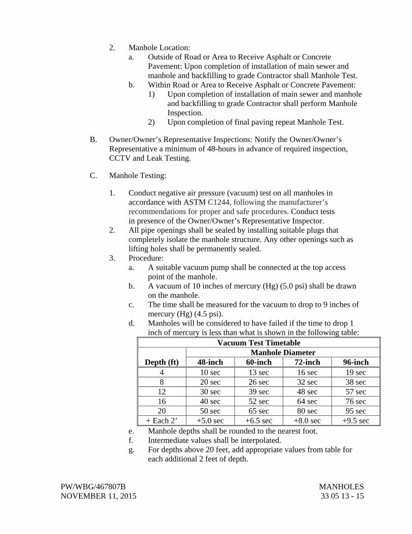
PW/WBG/467807B MANHOLES NOVEMBER 11, 2015 33 05 13 - 15
2. Manhole Location: a. Outside of Road or Area to Receive Asphalt or Concrete
Pavement: Upon completion of installation of main sewer and manhole and backfilling to grade Contractor shall Manhole Test.
b. Within Road or Area to Receive Asphalt or Concrete Pavement: 1) Upon completion of installation of main sewer and manhole
and backfilling to grade Contractor shall perform Manhole Inspection.
2) Upon completion of final paving repeat Manhole Test.
B. Owner/Owner’s Representative Inspections: Notify the Owner/Owner’s Representative a minimum of 48-hours in advance of required inspection, CCTV and Leak Testing.
C. Manhole Testing:
1. Conduct negative air pressure (vacuum) test on all manholes in accordance with ASTM C1244, following the manufacturer’s recommendations for proper and safe procedures. Conduct tests in presence of the Owner/Owner’s Representative Inspector.
2. All pipe openings shall be sealed by installing suitable plugs that completely isolate the manhole structure. Any other openings such as lifting holes shall be permanently sealed.
3. Procedure: a. A suitable vacuum pump shall be connected at the top access
point of the manhole. b. A vacuum of 10 inches of mercury (Hg) (5.0 psi) shall be drawn
on the manhole. c. The time shall be measured for the vacuum to drop to 9 inches of
mercury (Hg) (4.5 psi). d. Manholes will be considered to have failed if the time to drop 1
inch of mercury is less than what is shown in the following table: Vacuum Test Timetable
Depth (ft) Manhole Diameter
48-inch 60-inch 72-inch 96-inch 4 10 sec 13 sec 16 sec 19 sec 8 20 sec 26 sec 32 sec 38 sec 12 30 sec 39 sec 48 sec 57 sec 16 40 sec 52 sec 64 sec 76 sec 20 50 sec 65 sec 80 sec 95 sec
+ Each 2’ +5.0 sec +6.5 sec +8.0 sec +9.5 sec e. Manhole depths shall be rounded to the nearest foot. f. Intermediate values shall be interpolated. g. For depths above 20 feet, add appropriate values from table for
each additional 2 feet of depth.
MANHOLES PW/WBG/467807B 33 05 13 - 16 NOVEMBER 11, 2015
4. All manholes that fail the test or that have visible leakage in the manhole, even if passing the test, shall be repaired or replaced until the manhole passes the test, to the complete satisfaction of the Owner/Owner’s Representative. Manholes with visible leaks will not be accepted under any circumstances.
END OF SECTION