appendix 4 travel demand model methodology and … · quality conformity analysis ... model parsons...
TRANSCRIPT

APPENDIX APPENDIX APPENDIX APPENDIX 4444 to the to the to the to the REGIONAL REGIONAL REGIONAL REGIONAL TRANSPORTATION PLAN TRANSPORTATION PLAN TRANSPORTATION PLAN TRANSPORTATION PLAN 1111
APPENDIX 4
TRAVEL DEMAND MODEL METHODOLOGY AND AIR QUALITY CONFORMITY ANALYSIS
Contents Section 1 - Travel Demand Forecast Model Procedures and Assumptions
Section 2 - Population and Employment Forecasts
Section 3 - The Air Quality Conformity Process
Section 4 - Transportation Analysis Zones, Network and Travel Demand Model
Section 5 - Travel Demand Model Results and Regional Travel
Section 6 - Carbon Monoxide Mobile Source Emissions Forecasts
Section 7 - PM10 Modeling Assumptions
Section 8 - Finding of Air Quality Conformity
Section 9 - Transportation Control Measures
Section 10 - Transportation Improvement Impacts
Appendix 4-A - RTC 2009 Regional Travel Demand Model

2222 REGIONAL TRANSPORTATION COMMISSION OF SOUTHERN NEVADAREGIONAL TRANSPORTATION COMMISSION OF SOUTHERN NEVADAREGIONAL TRANSPORTATION COMMISSION OF SOUTHERN NEVADAREGIONAL TRANSPORTATION COMMISSION OF SOUTHERN NEVADA
1. Travel Demand Forecast Model Procedures and Assumptions
Background
The Las Vegas Regional Travel Demand Forecast Model follows established professional practice
through the implementation of the conventional “four step” travel demand forecasting process.
The first step is known as Trip Generation, in which person trips produced in and attracted to each
zone are calculated from the estimates of population, employment and other socio-economic
variables discussed in Appendix 3.Regional Forecasts. In the second step known as Trip
Distribution, these productions and attractions are associated with each other through algorithms
that develop a pattern of zone-to-zone movements. In the third step, Mode Choice, the zone-to-
zone person trip estimates are converted into auto trips based on average vehicle occupancy rate
and person transit trips. In the final step, the demand for vehicle travel is assigned to the street
network to give estimates of traffic flow and the demand for transit is assigned to the transit routes
to give transit ridership estimates.
The Regional Transportation Commission Travel Demand Forecast Model (RTC Model)
calculations are performed using the TRANSCAD software package developed by the Caliper
Corporation of Newton, Massachusetts. The RTC model was converted and has incorporated a
series of improvements in past 20 years. Table1. below provides the current RTC 2009 Model
chronology and components, and the evolutions of the main input assumptions and the model
procedures.
The major latest model and zone system updates in 2009 model include:
• The model was recalibrated with 2005 household survey data, 2005 transit on board survey
data, visitor survey data and 2005 traffic counts.
• Added area type model elements to reflect the future area type changes due to growth and
refine the link speeds by road facility type and by area type.
• Updated the truck model elements by linking the future truck volumes to the total growth in
the Las Vegas Valley.
• Enlarged and refined the zone system to include more Apex areas based on future land-use
development for the City of North Las Vegas and some other areas; increase the number of
zones from 1645 to 1658 (1647 internal zones plus 11 external zones),
• Updated Planning Variables –land use input data for the model and addition of network links.
An important part of the model improvement process has been a regular program of inter-agency
consultation among the RTC, local entities and the Nevada Department of Transportation (NDOT).
This was accomplished previously through the establishment of the Travel Demand Forecasting and
Modeling Subcommittee (TDFMS) and later has been accomplished through the regular Modeling
Working Group meetings. Many of the changes made have been discussed and refined through this
process.

APPENDIX APPENDIX APPENDIX APPENDIX 4444 to the to the to the to the REGIONAL TRANSPORTATION PLAN REGIONAL TRANSPORTATION PLAN REGIONAL TRANSPORTATION PLAN REGIONAL TRANSPORTATION PLAN 3333
Table 1. Model Chronology
Name of Model
Developer Release Date
Software Platform
Calibra- tion Year
# of TAZs
Features Utilized by RTC 2004 Model
Resort MIS Interim Mode Choice
Parsons Brinkerhoff Quade & Douglas
1995 Tranplan 1995 751 Model structure and mode choice model
Las Vegas Travel Demand Model
Parsons Brinkerhoff Quade & Douglas
2000 Tranplan 1995 1140 Visitor trip generation and distribution models; other trip matrix; Used trip rates developed from the 1996 household travel survey, estimation of visitor trips used data from the 1996 visitor and airport surveys
RTC Las Vegas Phase I Model
Caliper Corporation
2002 TransCAD 4.0
2000 1140 Time of day distribution; highway skims; feedback looping; 800 traffic count locations & 40 screen lines used for model calibration
RTC LV Phase I Model Update
Caliper Corporation
2003 TransCAD 4.6
2000 1218 Employment planning variables; highway network; highway assignment; cold start flows and VMT
RTC Phase 1A Regional Travel Model
Parsons Corporation
2003 TransCAD 4.6
2000 1218 Household planning variables; highway network classification; resident socioeconomic sub-models; resident trip generation and distribution models; auto occupancy models
RTC 2004 Model (Update Package 1)
Parsons Corporation
2006 TransCAD 4.7
2002/2003 1219 Updated planning variables, highway networks and link capacities; added special generators; initialized travel times; updated time of day distributions; updated transit share matrix
RTC 2004 Model (Update Package 2A)
Parsons Corporation
2008 TransCAD 4.8
2002/2003 1645 Added transit network and path-building processing, Mode Choice modeling, HOV procedures and transit assignment procedures. Added TAZs to include Boulder City area; Updated planning variables and highway networks.
RTC 2009 Model
Parsons Corporation
2012 TransCAD 4.8
2005 1658 Calibrated the model with 2005 household survey data, 2005 transit on board and visitor survey data and 2005 counts; Added area type model elements; updated truck model elements, updated planning variables, highway networks and transit coding.
Source: Regional Transportation Commission of Southern Nevada 2012

4444 REGIONAL TRANSPORTATION COMMISSION OF SOUTHERN NEVADAREGIONAL TRANSPORTATION COMMISSION OF SOUTHERN NEVADAREGIONAL TRANSPORTATION COMMISSION OF SOUTHERN NEVADAREGIONAL TRANSPORTATION COMMISSION OF SOUTHERN NEVADA
RTC Regional Travel Demand Model (without Mode Choice Element) Flow Chart 1.
Source: Regional Transportation Commission of Southern Nevada 2012

APPENDIX APPENDIX APPENDIX APPENDIX 4444 to the to the to the to the REGIONAL TRANSPORTATION PLAN REGIONAL TRANSPORTATION PLAN REGIONAL TRANSPORTATION PLAN REGIONAL TRANSPORTATION PLAN 5555
RTC Regional Travel Demand Model (without Mode Choice Element) Flow Chart 2.
Source: Regional Transportation Commission of Southern Nevada 2012
The latest version of the updated RTC model is named as RTC 2009 Model, it is employed in this
TIP and RTP development and air quality conformity determinations. For the whole RTC model
structure, refer to Appendix 4 4-A. RTC 2009 Regional Travel Demand Model.

6666 REGIONAL TRANSPORTATION COMMISSION OF SOUTHERN NEVADAREGIONAL TRANSPORTATION COMMISSION OF SOUTHERN NEVADAREGIONAL TRANSPORTATION COMMISSION OF SOUTHERN NEVADAREGIONAL TRANSPORTATION COMMISSION OF SOUTHERN NEVADA
2. Population and Employment Forecasts
2.1 Background
The key planning assumptions made as a foundation for the air quality emissions analysis and
Conformity Finding relate to the projection of future land use, population and employment. These
projections are used to determine future travel demand and travel patterns and the effect these will
have on mobile source emissions.
Recognizing the complexity of land use forecasting, the Southern Nevada Regional Planning
Coalition (SNRPC)1 formed a Land Use Working Group (LUWG) at the request of Regional
Transportation Commissions of Southern Nevada (RTC). The LUWG is responsible for providing
forecasted land use activity for the RTC. The LUWG consists of planning staff from Clark County
and the cities of Las Vegas, North Las Vegas, and Henderson. In accordance with inter-local
agreement and established practice, the population and employment projections used in this analysis
are based upon those developed by Clark County and local government land use planning staff. The
total projections then were matched to the total projections by the Center for Business and Economic
Research at the University of Nevada, Las Vegas (CBER). The CBER forecasts are for Clark
County as a whole. The land use projections are then converted into the RTC model input known as
Planning Variables (Land use, Population, Employment, etc.). For the detailed development of the
Planning Variable, refer to Appendix 3 of this RTP.
2.2 Clark County and Regional Population and Employment Forecasts
The RTC model covers the area generally known as the Las Vegas Valley, comprising the Cities of
Las Vegas, North Las Vegas and Henderson as well as those parts of unincorporated Clark County
lying within the Bureau of Land Management (BLM) Cooperative Land Sale and Exchange Area as
designated by the Southern Nevada Public Land Management Act of 2002 displayed in Figure 1-4 as
the BLM Disposal Boundary (2002). In addition to the above areas, the core areas of the Boulder
City is also included in the RTC modeling area. The Las Vegas Non-Attainment Area is defined as
Hydrographic Basin 212, which is centered on the Las Vegas Valley. It includes bordering upland
and mountain areas that are mostly uninhabited and that are held as open and recreational lands by
various Federal and State agencies. The few settlements within these outlying areas have a total
population of less than 2,000. In developing the Carbon Monoxide State Implementation Plan (CO
SIP), it was agreed between the local air planning agency and the US Environmental Protection
Agency (EPA) that it was acceptable to use the modeled area as a basis for estimating the mobile
source emissions to be used in setting the mobile source emission budgets and in subsequent
conformity determinations.
Most of the population in Clark County is concentrated in the Las Vegas Valley. Based upon
analyses performed in the mid-1990s, it has been estimated that 95 percent of the population of the
County lives within the valley. This percentage is embodied in a number of inter-local agreements
by various agencies involved in planning activity, including Clark County’s Planning Department,
the School District, the RTC, the Southern Nevada Regional Planning Coalition and the Southern
1 In its 1997 session, the Nevada State Legislature enabled the formation of the Southern Nevada Regional Planning
Authority (SNRPA). There are ten members in the Coalition membership and Board. Two elected officials are appointed by the governing body of each public entity (except Boulder City and the Clark County School District with one appoint member each). The SNRPC conducts some of its business through subcommittees.

APPENDIX APPENDIX APPENDIX APPENDIX 4444 to the to the to the to the REGIONAL TRANSPORTATION PLAN REGIONAL TRANSPORTATION PLAN REGIONAL TRANSPORTATION PLAN REGIONAL TRANSPORTATION PLAN 7777
Nevada Water Authority, and it is, therefore, used to calculate the population control total for the
Las Vegas Valley in the travel demand forecasting and air quality conformity process.
The future year land use forecast was created through the work of Southern Nevada Regional
Planning Coalition (SNRPC), Land Use Workgroup (LUWG) with the members representing the
cities of Las Vegas, North Las Vegas, Henderson, urbanized Clark County and the RTC. The
Workgroup was formed to develop a consensus based process to define future land use development
plans for the RTC’s transportation planning process. Based on the available vacant land of the
Assessor’s 2010 closed roll parcel, the group created Geographic Information System (GIS) data of
planned land development using the RTC/SNRPC planned land use development definition. This
future land use is in 5-year increments by jurisdiction covering the years from 2010 through 2035.
Table 2 sets out the forecast developed acres for 2010 to 2035.
There are two parts to the development of the land use forecast: 1) determining the current and
future land use development patterns and 2) converting the land use patterns to the planning
variables (PV) that are inputs to the travel demand forecast model.
Table 3 is the summary of the key PVs for the RTC Travel Demand Forecast (TDM) model.
The first column has the variable names to be used in the model. Refer to Regional
Transportation Plan (RTP) 2013-2035 Appendix 3 -Planning Variable Development and
Methodology for detailed planning variable definitions. The rest columns show the variable
totals for the modeling base year (2010) and horizon years (2015, 2020, 2030 and 2035) for the
RTP 2013-2035. Note that Clark County Department of Aviation (CCDOA) made initial
requests in May 2012 that the Southern Nevada Supplemental Airport (SNSA) is assumed to
open in 2025. Based on the request and confirmed with CCDOA in January 2013, the new
planning assumptions for the SNSA employment and enrollment for the horizon years 2030 and
2035 have been updated in this document in January 2013. Table 3 reflects the PVs changes. As
a result, all the tables including information for 2030 and 2035 in this section and the remaining
document have been updated after rerun of the models with new PV input.
Table 2. Forecast Developed Acres, 2010-2035
Time Period Residential Non_Residential Total
2010-2015 12,611 14,637 27,248
2015-2020 10,726 12,128 22,854
2020-2025 9,842 13,706 23,548
2025-2030 7,709 10,015 17,724
2030-2035 6,110 12,623 18,733
Total 46,998 63,110 110,108
Non-Residential includes open space Source: RTC, Planning Variable Development and Methodology, 2012

8888 REGIONAL TRANSPORTATION COMMISSION OF SOUTHERN NEVADAREGIONAL TRANSPORTATION COMMISSION OF SOUTHERN NEVADAREGIONAL TRANSPORTATION COMMISSION OF SOUTHERN NEVADAREGIONAL TRANSPORTATION COMMISSION OF SOUTHERN NEVADA
Table 3. Summary of Planning Variables 2010-2035
FIELD Year 2010 Year 2015 Year 2020 Year 2030 Year 2035
2020 % of 2010
2030 % of 2010
2035 % of 2010
POP 1,915,984 2,155,796 2,349,683 2,602,601 2,682,047 123% 136% 140%
DU 794,813 886,695 967,225 1,058,999 1,088,087 122% 133% 137%
ODU 731,706 816,093 890,095 974,997 1,002,105 122% 133% 137%
HH_SIZE 3,069 3,188 3,267 3,374 3,484
INC 3,794 3,922 4,030 4,128 4,245
TOTEMP 794,486 890,730 960,906 1,117,524 1,187,142 121% 141% 149%
HOTEL 247,199 279,397 290,396 329,895 346,394 117% 133% 140%
OFFICE 146,997 175,086 196,086 233,086 250,886 133% 159% 171%
INDUST 68,570 65,954 72,307 96,134 104,357 105% 140% 152%
OTHER_NON 181,040 200,214 219,437 253,529 269,926 121% 140% 149%
RETAIL 150,680 170,080 182,679 204,879 215,579 121% 136% 143%
NAFB 13,000 13,500 14,000 15,000 15,000 108% 115% 115%
MIA_EMP 15,000 17,000 20,000 24,000 24,000 133% 160% 160%
MIA_PASS 108,924 123,300 137,000 165,000 165,000 126% 151% 151%
IVPH_EMP 0 0 0 5,117 6,647
IVPH_PASS 0 0 0 42,059 54,636
UNLV_MAIN_EMP 2,998 3,250 3,550 4,100 4,100 118% 137% 137%
UNLV_MAIN_ENR 28,203 30,600 33,500 38,734 38,734 119% 137% 137%
UNLV_NLV_EMP 0 0 0 120 500
UNLV_NLV_ENR 0 0 0 1,000 4,500
NEV_ST_COLL_EMP 140 400 600 1,000 1,200 429% 714% 857%
NEV_ST_COLL_ENR 2,964 5,000 7,500 12,500 15,000 253% 422% 506%
F18 215,201 219,551 232,801 243,601 249,851 108% 113% 116%
F912 87,636 90,336 95,736 101,136 101,136 109% 115% 115%
F13 32,456 37,625 37,625 37,625 37,625 116% 116% 116%
MED_INC 60,928,408 63,220,875 65,179,466 66,856,993 68,791,146
Source: Regional Transportation Commission staff. January, 2013. Planning variable values for SNSA Employment and Enrollment have been updated in January 2013. Note: The FIELD name IVPH in the table represents the SNSA
Figure 1.
Population, Households and Total Employment
2015 2020 2030 20350
500,000
1,000,000
1,500,000
2,000,000
2,500,000
3,000,000
RTP Horizon Years
Esti
mate
d P
op
, h
ou
seh
old
s a
nd
Em
plo
ym
en
t Year
Population
Households
Total Employment
Source: Regional Transportation Commission staff, January, 2013

APPENDIX APPENDIX APPENDIX APPENDIX 4444 to the to the to the to the REGIONAL TRANSPORTATION PLAN REGIONAL TRANSPORTATION PLAN REGIONAL TRANSPORTATION PLAN REGIONAL TRANSPORTATION PLAN 9999
Figure 1. shows the growths of the population, occupied dwelling units (households) and total
employment for the plan forecast horizon years. The growth looks flat from 2030 to 2035
because the time interval is shorter.
In addition to total population, households and employment, the model utilizes certain other
socio-economic indicators. These include average household income, school enrollment, and
various classes of employment. The number of dwellings in each zone was estimated from land
use data on the extent of residential land, using density and occupancy factors derived from the
2010 Census and local entity sources. Medium household income is from the Census and school
enrollment were also developed from local sources. A detailed description of the methodology
is provided in Appendix 3.
3. The Air Quality Conformity Process and Travel Demand Results
3.1. Introduction This section describes the air quality conformity analysis conducted as part of the update of the
Regional Transportation Plan (RTP) 2013-2035, and the Transportation Improvement Program
(TIP) for Fiscal Years 2013-2016.
Since 1991, air quality and transportation have been linked through a process known as
transportation plan conformity. Conformity is a demonstration that the levels of emissions from
travel on the transportation system are consistent with the goals for air quality in the State
Implementation Plan (SIP) that is a control plan developed by the state air quality planning
agency. The SIP defines how the area will act to improve air quality to meet the NAAQS and
includes emission targets or pollution limits expressed as “budgets” for transportation related
emissions. These standards are set for a number of pollutants that cause respiratory diseases and
other health problems. A region that exceeds the maximum daily threshold for a given pollutant
is defined in the NAAQS as being in non-attainment. Non-attainment is the term used to describe
levels of these pollutants that the U.S. Environmental Protection Agency (EPA) has designated
as not meeting the clean air standards for that pollutant as defined in the NAAQS. The Clean Air
Act Amendments of 1990 (CAAA) require that each non-attainment area and pollutant be
addressed by the SIP.
The NAAQS define six primary pollutants:
1. Carbon monoxide (CO),
2. Particulate matter 10 microns in size or less - PM10;
3. Ozone - O3,
4. Sulfur dioxide,
5. Lead, and
6. Nitrous oxides – Nox.
Much of these regulated pollutants are produced by automobiles and other road transportation
and are classified as “mobile source emissions”.
The Las Vegas region was in non-attainment for three pollutants: CO, PM10, and Ozone. The
Las Vegas region conformity status have changed in the recent years and the changes are

10101010 REGIONAL TRANSPORTATION COMMISSION OF SOUTHERN NEVADAREGIONAL TRANSPORTATION COMMISSION OF SOUTHERN NEVADAREGIONAL TRANSPORTATION COMMISSION OF SOUTHERN NEVADAREGIONAL TRANSPORTATION COMMISSION OF SOUTHERN NEVADA
described in Section 3.2 (A) in this document. Figure 2 shows the Clark County Boundary,
RTC Transportation Analysis Zones (TAZ), road networks, and the study boundaries for
pollutants. The former Ozone non-attainment area, which extends from the Las Vegas Valley
south and east to the Colorado River, was re-designated as attainment by EPA in 2012. Within
Clark County, the area defined as Hydrographic Basin 212 was designated as a non-attainment
area for two pollutants – CO and PM10. This area is roughly coincides with the Las Vegas
Valley. On September 15, 2004 the EPA designated about 60 percent of Clark County as non-
attainment for O3. This area extends from the Las Vegas Valley south and east to the Colorado
River.

APPENDIX APPENDIX APPENDIX APPENDIX 4444 to the to the to the to the REGIONAL TRANSPORTATION PLAN REGIONAL TRANSPORTATION PLAN REGIONAL TRANSPORTATION PLAN REGIONAL TRANSPORTATION PLAN 11111111
Figure 2. Clark County and RTC Non-Attainment Areas

12121212 REGIONAL TRANSPORTATION COMMISSION OF SOUTHERN NEVADAREGIONAL TRANSPORTATION COMMISSION OF SOUTHERN NEVADAREGIONAL TRANSPORTATION COMMISSION OF SOUTHERN NEVADAREGIONAL TRANSPORTATION COMMISSION OF SOUTHERN NEVADA
Any RTP/TIP must include a determination that implementation will result in reduction of these
pollutants to acceptable levels in ways that conform to the SIP. The term “conformity” describes
the determination of this acceptable result. Supporting the determination is a complex modeling
process that is based on assumptions about what happens if existing conditions are extended into
the future and about what happens if the projects and programs in the RTP/TIP are implemented.
A conforming RTP/TIP model outcome projects that the regulated pollutants will be reduced to
acceptable levels within time frames that meet the NAAQS.
3.2. Conformity Guidelines
This Section outlines the complex technical evaluation process involved in the conformity
demonstration. Descriptions of other aspects of the process are provided in the Appendices,
including a list of the projects included in the TDM and details of the Air Quality and
Transportation Control Measures assumed in the Model.
RTC's Vision Statement is to provide “a safe, clean, effective regional transportation system that
enhances mobility and air quality for our citizens and visitors”. To that end, the Commission
has adopted the following goal for the transportation planning process:
“Implement transportation systems that improve air quality and protect the environment”
The specific procedures for reaching this goal are those established under Federal law for
ensuring conformity between transportation plans and air quality improvement plans. This
process of conformity is intended to ensure that the projects and programs proposed in the RTP,
TIP and TIP amendments conform to the purpose of the CAAA and the SIPs. This means
“...conformity to the (implementation) plan’s purpose of eliminating or reducing the severity and
number of violations of the national ambient air quality standards and achieving expeditious
attainment of such standards...”. The provisions of the CAAA in relation to conformity are
amplified in the EPA Final Rule, 40 CFR Part 93, as amended September 15, 1997. The
conformity determination described in this section was performed in accordance with US DOT
and EPA guidance and procedures, and also in accordance with the Transportation Conformity
SIP, “Transportation Conformity Plan for the Las Vegas Valley Nonattainment Area”, Clark
County Board of Commissioners, 2008
A. State Implementation Plans
The SIP is a federally required document that defines strategies to ensure the existing and future
attainment of the NAAQS as defined by the EPA. The SIP sets out policies and actions to ensure
that air quality meets the NAAQS within a time frame determined under the EPA regulations.
For metropolitan planning organizations (MPOs), the SIP also establishes a mobile source
emissions budget that is used in the evaluation of transportation plan conformity. A
transportation plan is in conformance with the objectives of the SIP when the predicted tailpipe
emissions from all travel, as defined in the long-range plan, is at or below the budget thresholds
for all of the horizon years that comprise the RTP. In southern Nevada, responsibility for
developing the SIP is delegated by the State of Nevada to Clark County. The Clark County
Department of Air Quality (DAQ) is tasked with SIP development. Under the provisions of the

APPENDIX APPENDIX APPENDIX APPENDIX 4444 to the to the to the to the REGIONAL TRANSPORTATION PLAN REGIONAL TRANSPORTATION PLAN REGIONAL TRANSPORTATION PLAN REGIONAL TRANSPORTATION PLAN 13131313
CAAA, the RTC of Southern Nevada, as the MPO for the region, is the agency responsible for
making the determination of conformity.
The Las Vegas area was in non-attainment for three pollutants:PM10, Carbon Monoxide, and
Ozone. The Las Vegas area conformity status have changed in the recent years. The current
conformity status of these three pollutants are:
• PM10 – The Las Vegas Valley is currently in non-attainment. The EPA made a determination
that the Las Vegas Valley is in attainment with the NAAQS on August 3, 2010 (75 FR 45485), and
will redesignate to attainment upon approval of the pending Maintenance Plan and request for
redesignation submitted by the DAQ.
•
• CO – A Maintenance Plan and formal request for redesignation to attainment was
submitted by the DAQ to the EPA in 2008 and was approved on September 27 2010.
•
• Ozone – On May 29, 2010, the EPA approved the emission budgets included in the Early
Progress Plan for Ozone. In March 2011, the DAQ submitted Ozone Redesignation
Request and Maintenance Plan to the EPA. The EAP made the determination that Clark
County is in attainment with the 1997 Ozone NAAQS on March 29, 2011 (76 FR 17343).
On December 20, 2012, EPA Regional Administrator Jared Blumenfeld signed a Federal
Register notice redesignating Clark County to attainment for the 1997 8-hour ozone
standard and approving the associated Maintenance Plan.
•
The Las Vegas region has approved SIPs for PM10, CO and Ozone Maintenance Plan. The
PM10 SIP was approved by EPA on July 9, 2004. The EPA approved the original CO SIP in
2004, and then approved the 2006 CO SIP revision on August 7, 2006 with an effective date of
September 6, 2006. The CO emission budgets have recently been updated as part of the CO
Maintenance SIP approved September 27, 2010. On December 20, 2012, the EPA signed a
Federal Register notice redesignating Clark County to attainment for the 1997 8-hour ozone
standard and approving the associated Maintenance Plan. The new budgets in the Maintenance
Plan took effect in January 2013. As a result of 2012 re-designation and revocation of the
1997 ozone standard by EPA on July 20, 2013, the RTC is no longer required to do
conformity analysis for Ozone.
B. Regional Emissions Analysis: Budgets for CO, PM10 and Ozone
The PM10 budgets, the updated budgets for CO and Ozone budgets established in the
Maintenance Plan are used in the conformity findings for this 2013-2035 RTP and 2013-2016
TIP. These budgets are shown in Table 4, Table 5 and Table 6.
The principal step toward making a conformity determination is to demonstrate that the
anticipated levels of atmospheric pollution which will result from planned and programmed
transportation projects will be less than the relevant budgets defined in the SIPs.
CO budgets for mobile source emissions in the CO Maintenance SIP approved in September
2010 are shown in Table 4.

14141414 REGIONAL TRANSPORTATION COMMISSION OF SOUTHERN NEVADAREGIONAL TRANSPORTATION COMMISSION OF SOUTHERN NEVADAREGIONAL TRANSPORTATION COMMISSION OF SOUTHERN NEVADAREGIONAL TRANSPORTATION COMMISSION OF SOUTHERN NEVADA
Table 4. Mobile Source CO Emission Budgets for the Las Vegas Region
Year CO Emission Budget (tons per day)
2008 658
2010 686
2020 704
Source: Clark County DAQ, Carbon Monoxide Maintenance SIP, September 2010
For PM10, the SIP budget established for 2003 to demonstrate reasonable further progress (RFP)
towards attainment of the 24-hour standard, and the budget established for the attainment year of
2006 apply to the conformity determination and are set out in Table 5. The budget year 2006 is
used for all horizon years for this RTP /TIP analysis.
Table 5. Mobile Source PM10 Emission Budgets for the Las Vegas Region
Year PM10 Emission Budget (tons per day)
2003 155.77 (24-hour RFP)
2006 141.41 (24-hour standard)
Source: Clark County DAQEM, PM10 SIP July 2004
The new budgets in the Ozone Maintenance Plan take effect in January 2013 and replace the
budgets in Ozone Early Progress Plan. These budgets are defined for the two precursors of
Ozone, Volatile Organic Compounds (VOC) and the Oxides of Nitrogen (NOX), as set out in
Table 6. Note that the emission budgets are for the whole Clark County, not only the Ozone
non-attainment area. However, as stated in the last section, after the 2012 re-designation and
revocation of the 1997 ozone standard by EPA on July 20, 2013, the RTC is no longer
required to do conformity analysis for Ozone.
Table 6. Mobile Source Ozone Emission Maintenance Budgets for Clark County
Precursors(tons/day) 2008 Base 2015 Base 2022 Attainment
Volatile organic compounds 65.08 45.32 36.71
Nitrogen Oxides 68.46 34.69 23.15
Source: From Table 7-1. Motor Vehicle Emissions Budgets in the Clark County Ozone Maintenance Plan, Page 7-1.
3.3. Regional Emissions Analysis
A. Consultation on Conformity Procedures
The technical procedures used to determine the SIP budgets and to demonstrate conformity are
developed in conjunction with local entities through the DAQ Technical Advisory Committee
(TAC).
DAQ’s TAC reports to the Executive Advisory Committee of the Clark County Board of
Commissioners. This technical committee consists of staff representatives from Clark County,
the RTC, the Cities of Boulder City, Henderson, Las Vegas and North Las Vegas, and the
NDOT, as well as members from industry and from the public. The DAQ website is at
http://www.co.clark.nv.us/air_quality/index.htm.

APPENDIX APPENDIX APPENDIX APPENDIX 4444 to the to the to the to the REGIONAL TRANSPORTATION PLAN REGIONAL TRANSPORTATION PLAN REGIONAL TRANSPORTATION PLAN REGIONAL TRANSPORTATION PLAN 15151515
Consultation between local and Federal agencies is maintained through the inter - agency
consultation procedures contained in the Transportation Conformity SIP, “Transportation
Conformity Plan for the Las Vegas Valley Nonattainment Area”, Clark County Board of
Commissioners, January 2008. These procedures include periodic meetings of the Air Quality
Conformity Working Group.
The Air Quality Conformity Working Group meets monthly and discusses a variety of topics
related to air quality issues. It consists of representatives from each of RTC’s member entities,
in addition to representatives of the Federal Highway Administration, Federal Transit
Administration, and the EPA. The main focus of these meetings is to avoid delay in the
conformity process by coordinating air quality and conformity discussions.
B. Horizon Analysis Years
Under Federal Regulations, conformity has to be determined for a series of “Horizon” years.
These must include the designated attainment year, if applicable, and the last year of the
Transportation Plan and they must be not more than 10 years apart. For this conformity
determination, the following horizon years are used: 2015, 2020, 2030 and 2035 for all three
pollutants.
A second component of a conformity determination is an assessment of the progress in
implementing Traffic Control Measures (TCMs). These measures are intended to reduce
emissions or concentrations of pollutants from transportation sources by reducing vehicle use or
otherwise reducing vehicle emissions.
As part of the conformity process, the RTC has to certify that TCMs identified in the SIPs are
being implemented on schedule and that no federal funds are being diverted from these projects
in such a way as to delay their timely implementation. The scope and status of TCMs is further
discussed in Section 9 of this document with additional details.
C. Conformity Determination Technical Methodology
The calculation of mobile source emissions for each horizon year involves several steps, and
these are described in the remaining sections of this chapter, as follows:
• The underlying assumptions regarding population and employment change in the region are
outlined in the previous section.
• All regionally significant transportation projects are included in the Travel Demand
Forecast model, which is then used to forecast vehicle miles of travel (VMT) and travel
speeds in the region.
• The emission model MOVES is then used to develop emission factors for CO and PM10,
that indicate how much pollutant are produced for each vehicle mile of travel. These
factors are applied to the forecasts from the travel demand model to derive the modeled
total of mobile source CO and PM10 emissions.
• The emission benefits from the TCMs are then subtracted from the modeled vehicle
emissions to produce a forecast of net mobile source emissions.
• The procedures for establishing PM10 concentrations are described later.

16161616 REGIONAL TRANSPORTATION COMMISSION OF SOUTHERN NEVADAREGIONAL TRANSPORTATION COMMISSION OF SOUTHERN NEVADAREGIONAL TRANSPORTATION COMMISSION OF SOUTHERN NEVADAREGIONAL TRANSPORTATION COMMISSION OF SOUTHERN NEVADA
The predicted net CO, and PM10 emissions that result from these procedures are then compared
with the mobile source emissions budgets described above. The results are set out in Sections 6,
7 and 8.
4. Transportation Analysis Zones, Network and Travel Demand Forecast
Model
4.1. Transportation Analysis Zones
As noted in sub-section 1.1 and 1.2., the socio-economic data used in the model is disaggregated
into 1647 internal Transportation Analysis Zones (TAZs). There are 11 external zones. The total
modeling area covers basically the whole Las Vegas Valley, including the whole City of Las
Vegas, City of Henderson, City of North Las Vegas, the core areas of the Boulder City, other
communities and unincorporated areas in the valley and some other areas north and northwest to
the City of North Las Vegas, industrial areas northeast to the City of North Las Vegas, and areas
around SNSA. Most TAZs are bounded by highway or major streets. Railroads and natural
barriers such as major washes are also used to define zone boundaries. Zones range from 0.25 to
0.5 sq. mile in most of the developed parts of the region and often 1 sq. mile in the suburbs. See
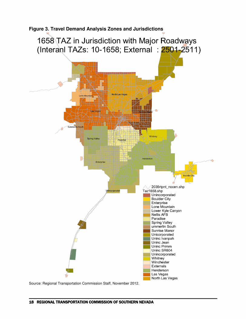
Figure 3 for the Travel Demand Analysis Zones
4.2. Model Networks
The travel demand modeling process begins with the identification of the streets and highways to
be included in the network. The model network includes all roads that are federally classified as
collectors or above, as well as streets that are included in the consolidated Master Plan for Streets
and Highways for the Las Vegas Valley. Each link in the network is defined by a number of
attributes. The main attributes are:
• Link length
• Number of lanes (*)
• Posted speed limits (*)
• Roadway group
• Area type
• Free-flow speed
• Capacity and
• Speed-capacity equation coefficients.
The attributes denoted by an asterisk are coded using a variety of sources, including geographic
files maintained by the Clark County GIS Management Office (GISMO), survey photography,
local entity records and field checking. Network roads are grouped into fourteen facility types
and four area types. These classifications are used to enter default values for other roadway
attributes such as free-flow speed and capacity and also to summarize system performance.
The six area types are:
1. Central Business District of the City of Las Vegas

APPENDIX APPENDIX APPENDIX APPENDIX 4444 to the to the to the to the REGIONAL TRANSPORTATION PLAN REGIONAL TRANSPORTATION PLAN REGIONAL TRANSPORTATION PLAN REGIONAL TRANSPORTATION PLAN 17171717
2. Resort Corridor
3. Other areas characterized by urban density and land use, and
4. Suburban areas.
5. External areas
6. Rural areas.
The roadway facility types are based on generalized descriptions of the type of facility. They
include:
• Interstates
• Other freeways
• High-Occupancy Vehicle (HOV)lanes,
• Expressways / Beltways
• Two classes of arterial roads (Major and Minor)
• Collectors
• Local roads
• Other roads used by transit
• Two classes of ramps (Ramp and System Ramp)
• Zone centroid connector links
• External connector links
• Transit access links
Table 7. Free-Flow Speeds
Free-Flow Speeds by Area Type
Functional Class CBD Resort Urban Suburban
System Ramps 40 40 51 53
Minor Arterials 31 31 36 41
Major Arterials 31 33 39 43
Ramps 15 25 28 36
Interstates 53 53 56 60
Freeways 51 51 54 59
Expressways 50 50 50 50
Collectors 29 29 33 39
Other 29 29 33 39 HOV 53 53 56 60
Source: Regional Transportation Commission, RTC 2009 Model
The free-flow speeds and capacities are set to default values in look up tables for each facility
type and area type. The values for free-flow speeds are set out in Table 7 and capacities in Table
8.
18181818 REGIONAL TRANSPORTATION COMMISSION OF SOUTHERN NEVADAREGIONAL TRANSPORTATION COMMISSION OF SOUTHERN NEVADAREGIONAL TRANSPORTATION COMMISSION OF SOUTHERN NEVADAREGIONAL TRANSPORTATION COMMISSION OF SOUTHERN NEVADA
Figure 3. Travel Demand Analysis Zones and Jurisdictions
Source: Regional Transportation Commission Staff, November 2012.

APPENDIX APPENDIX APPENDIX APPENDIX 4444 to the to the to the to the REGIONAL TRANSPORTATION PLAN REGIONAL TRANSPORTATION PLAN REGIONAL TRANSPORTATION PLAN REGIONAL TRANSPORTATION PLAN 19191919
Table 8. Free-Flow Capacities
Free-Flow Capacity by Area Type
Functional Class CBD Resort Urban Suburban
System Ramps 2,000 2,000 2,000 2,000
Minor Arterials 560 600 600 640
Major Arterials 700 750 750 800
Ramps 1,600 1,600 1,600 1,600
Interstates 2,000 2,000 2,000 2,000
Freeways 2,000 2,000 2,000 2,000
Expressways 1200 1200 1200 1200
Collectors 420 450 450 480
Other 416 416 416 416
HOV 1,950 1,950 1,950 1,950
Source: Regional Transportation Commission, RTC 2009 Model
The speed-capacity equation coefficients were developed as a part of the model calibration
process and reflect the observed characteristics of different types of roadway in the area. They
are used in the assignment process to control the relationship between traffic flow, capacity and
congested time.
4.3. Horizon Year Networks
The development of the future year networks begins with the identification and selection of
“regionally significant” capacity-adding transportation projects that are financially constraint and
are proposed for inclusion in the RTP and TIP. The definition of regional significance is that
contained in Section 2.2 of the RTCs “Policies and Procedures”, as amplified through the
inter-agency consultative procedures laid down in the “Transportation Conformity Plan for the
Las Vegas Valley Nonattainment Area”, Clark County Board of Commissioners, March 2005,
and in 40 CFR 93 S.93.101. All such projects are included, by their planned completion year, in
the future networks, irrespective of funding source.
Projects are categorized by anticipated horizon year of completion, i.e., 2015, 2020, 2030 or
2035. Alignments, design scope and attributes for new roads, and changes in the attributes of
existing roads, are defined by NDOT and the local entities as part of the TIP process. Projects
included in the model analysis are listed in Appendix I Capital Program Projects.
Table 9 summarizes the contents of the 2013, 2015, 2020, 2030 and 2035 networks. In total, the
2013 network covers approximately 3,711 link miles of roadway in the region, as well as links
representing the minor roads that connect zone centroids to the network, and roads leading into
and out of the region. The 2035 network has 4,090 link miles and 11,985 lane miles coded in the
network. Table 9 shows the link mile and lane mile changes between horizon years. The
changes to centroid connector links are set to zero, because these changes are not necessarily
caused by the projects, but by the reconfiguration, for coding purposes only, of the zone
connections to the future network. Table 11 shows that all projects included in this RTP will
result in 458 more link miles and 1,768 more lane miles for the Valley between 2013 and 2035.
These numbers are smaller than that in RTC 2009-2030 RTP for the horizon years between 2013
and 2030. This is easy to understand that the total projects in this RTP are fewer due to the
reduction in transportation funding after the most recent recession.

20202020 REGIONAL TRANSPORTATION COMMISSION OF SOUTHERN NEVADAREGIONAL TRANSPORTATION COMMISSION OF SOUTHERN NEVADAREGIONAL TRANSPORTATION COMMISSION OF SOUTHERN NEVADAREGIONAL TRANSPORTATION COMMISSION OF SOUTHERN NEVADA
Table 9. Network Link Miles and Lane Miles by Roadway Type
2013 2015 2020 2030 2035
Description Link
Miles Lane Miles
Link Miles
Lane Miles
Link Miles
Lane Miles
Link Miles
Lane Miles
Link Miles
Lane Miles
External Links 44.14 92.95 44.14 92.97 44.14 92.97 44.14 98.24 44.14 98.24
System-System Ramp 23.90 35.70 23.90 35.70 33.15 50.76 38.42 64.59 45.77 73.04
Minor Arterial 421.83 1,717.77 427.75 1,764.74 447.19 1,892.86 525.09 2,260.20 550.52 2,406.17
Major Arterial 462.80 2,242.42 491.95 2,434.72 500.15 2,516.00 536.27 2,708.00 546.58 2,787.99
Ramp 150.19 194.82 153.04 199.22 156.85 205.49 170.05 229.24 178.80 239.12
Interstate 205.49 625.29 205.49 625.29 205.49 615.94 205.49 620.75 205.49 628.05
Freeway 94.36 277.59 96.56 286.43 139.74 385.55 156.34 465.16 168.05 495.64
Expressway/Beltway 26.14 62.54 26.14 62.54 17.05 34.39 18.95 75.63 18.95 75.63
Collector 714.90 1,948.39 694.69 1,908.77 691.94 1,940.41 740.41 2,096.14 742.18 2,096.06
Centroid Connector 1,474.16 2,952.29 1,456.38 2,916.83 1,439.74 2,883.54 1,407.42 2,818.91 1,405.67 2,815.41
Local 32.54 72.16 34.17 75.43 32.24 71.84 36.47 80.29 36.47 80.39
HOV Lanes 21.70 21.70 22.00 22.00 48.57 62.54 71.91 85.88 71.91 85.88
Transit Link 32.97 49.36 32.97 49.36 56.28 75.85 56.28 75.85 68.38 87.95
Transit Access Link 6.24 12.47 6.34 12.68 7.52 15.03 7.52 15.03 7.52 15.03
TOTAL 3,711 10,305 3,716 10,487 3,820 10,843 4,015 11,694 4,090 11,985
Source: Regional Transportation Commission staff, September, 2013
Table 10. Changes in Link Miles and Lane Miles over the Previous Horizon Year
2013 2015 2020 2030 2035
Description Link Miles
Lane Miles
Link Miles
Lane Miles
Link Miles
Lane Miles
Link Miles
Lane Miles
Link Miles
Lane Miles
External Links 0 0 0.01 0.01 0.00 0.00 0.00 5.28 0.00 0.00
System-System Ramp 0 0 0.00 0.00 9.25 15.05 5.27 13.84 7.35 8.44
Minor Arterial 0 0 5.92 46.98 19.44 128.12 77.90 367.34 25.44 145.98
Major Arterial 0 0 29.15 192.30 8.20 81.28 36.12 192.00 10.32 79.99
Ramp 0 0 2.85 4.40 3.81 6.27 13.20 23.75 8.75 9.88
Interstate 0 0 0.00 0.00 0.00 -9.36 0.00 4.81 0.00 7.30
Freeway 0 0 2.21 8.83 43.18 99.13 16.59 79.61 11.71 30.48
Expressway/Beltway 0 0 0.00 0.00 -9.08 -28.15 1.90 41.24 0.00 0.00
Collector 0 0 -20.21 -39.63 -2.75 31.64 48.47 155.74 1.76 -0.09
Centroid Connector 0 0 0.00 0 0.00 0.00 0.00 0.00 0.00 0.00
Local 0 0 1.64 3.27 -1.93 -3.59 4.23 8.46 0.00 0.10
HOV Lanes 0 0 0.30 0.30 26.58 40.55 23.33 23.33 0.00 0.00
Transit Link 0 0 0.00 0.00 23.31 26.49 0.00 0.00 12.10 12.10
Transit Access Link 0 0 0.10 0.21 1.18 2.36 0.00 0.00 0.00 0.00
TOTAL 21.96 216.68 121 390 227 915.39 77 294
Source: Regional Transportation Commission staff. September 2013

APPENDIX APPENDIX APPENDIX APPENDIX 4444 to the to the to the to the REGIONAL TRANSPORTATION PLAN REGIONAL TRANSPORTATION PLAN REGIONAL TRANSPORTATION PLAN REGIONAL TRANSPORTATION PLAN 21212121
Table 11. Total Changes in Link Miles and Lane Miles from 2013 to 2035 Network
Total Changes from 2013 to 2035
Description Link Miles Lane Miles
External Links 0.01 5.29
System to System Ramp 21.86 37.33
Minor Arterial 128.69 688.41
Major Arterial 83.78 545.57
Ramp 28.62 44.30
Interstate 0.00 2.76
Freeway 73.70 218.05
Expressway/Beltway -7.19 13.08
Collector 27.28 147.66
Centroid Connector 0.00 0.00
Local 3.94 8.24
HOV Lanes 50.21 64.18
Transit Link 35.40 38.58
Transit Access Link 1.28 2.56
TOTAL 448 1,816
Sources: Regional Transportation Commission staff. September 2013
In Table 10 and Table 11, there are some negative numbers, especially for interstate lane miles
and for both link miles and lane miles for expressway / beltway for horizon year 2020. The
reasons for that are the following: By 2020, the facility type for I215 between Tenaya and 5th
Street is converted from expressway/ beltway to freeway with the project completion on that
segment of the road, this conversion in facility type causes both link miles and lane miles for
expressway / beltway reduced from the existing levels; New HOV lanes will be striped on I15
between Spaghetti Bowl and north of Blue Diamond from the existing interstate lanes, making
the number of general interstate lanes on the facility fewer than before and thus a shorter total
interstate lane miles in horizon year 2020; Other small lane mile reductions in 2020 from
previous horizon years are also caused by facility type changes due to roadway projects. In all
the above cases, if the link miles and /or lane miles reduce for one roadway facility type, the link
miles and /or lane miles for another roadway facility type should increase.
4.4. No-Build versus Build Networks
There is no longer any requirements to perform Build / No-Build tests to establish conformity
with the approval of the budgets for VOC and NOx in the Ozone Early Progress Plan.
4.5. Transit Network, HOV and Park-and-Ride
Since the last 2009-2030 RTP, transit network skims, mode choice and transit assignments have
been modeled for the Las Vegas modeling area. In addition, High Occupancy Vehicle (HOV)
and Park –and Ride (PnR) facilities are also coded in the network, and the HOV and PnR trips
are modeled too.

22222222 REGIONAL TRANSPORTATION COMMISSION OF SOUTHERN NEVADAREGIONAL TRANSPORTATION COMMISSION OF SOUTHERN NEVADAREGIONAL TRANSPORTATION COMMISSION OF SOUTHERN NEVADAREGIONAL TRANSPORTATION COMMISSION OF SOUTHERN NEVADA
Figure 4. 2035 Transit Routes
Source: Regional Transportation Commission staff. September 2013
Figure 4. presents a map showing the 2035 transit network routes and Park and Ride facilities
coded in the Transportation Demand Model networks. RTC Transit system Map and Schedules
published before Summer 2012 were used for the transit network coding for the Regional
Transportation Plan. Future transit supplies have been assumed to be the same level as that for
2012 as capital and operation funding for future transit improvements can not be identified when
this 2013-2035 RTP was being prepared. Therefore, RTC published (before summer 2012)
transit routes and schedules were used for the coding of the transit networks for all horizon years
for this RTP and the existing routes and schedules for the year of 2012 are coded in our travel
demand model networks in a way that best reflects current condition.
5. Travel Demand Forecast Model Result and Regional Travel
The RTC 2009 Travel Demand Forecast Model, a full four step travel demand model with visitor
model elements is used to develop the following model results. A full description of the each
step of the RTC Travel Demand Model is contained in Appendix II B Travel Demand Model
Documentation, Regional Transportation Plan FY 2006-2030 October 2006, by Regional

APPENDIX APPENDIX APPENDIX APPENDIX 4444 to the to the to the to the REGIONAL TRANSPORTATION PLAN REGIONAL TRANSPORTATION PLAN REGIONAL TRANSPORTATION PLAN REGIONAL TRANSPORTATION PLAN 23232323
Transportation Commission. Additional reference can be found in Appendix 4-A - RTC 2004
Regional Travel Demand Model Package 2- Transit processing and mode Choice Modeling
capabilities in Regional Transportation Plan FY 2013-2030, by Regional Transportation
Commission in 2008.
This section summarizes the modeling results from the each step of the RTC 2009 Travel
Demand Model for Update of 2013-2035 Regional Transportation Plan (2013-2035 RTP). The
2013-2035 RTP completed in Feb 2013 has been updated with Fuel Tax Indexing AB413 Bill.
The passage of Fuel Tax Indexing (FTI) in Clark County will result in numerous projects to be
implemented over the next 3 to 5 years. RTC staff analyzed the FTI project list and modeled all
projects which were regionally significant or added vehicular capacity to arterials. Projects on
local roads, resurfacing projects, intersection improvements, road retrofits for Complete Streets
design, bicycle and/or pedestrian projects, or intelligent transportation systems projects were not
modeled.
5.1. Trip generation
Trip Generation is the process of generating estimates of the person trips produced in, or
attracted to, each zone. Table 12 summarizes the total number of person trips generated by the
trip generation step of the travel demand model.
Table 12. Person-Trips in the Las Vegas Valley, 2015-2035
Average Weekday Person Trips
Trip Purpose 2015 2020 2030 2035
Home-Based Work 1,024,340 1,105,042 1,285,153 1,365,213
Home-Based School 578,575 634,089 726,117 746,638
Home-Based Shopping 622,598 679,966 770,419 787,162
Other Home-Based 2,978,579 3,253,038 3,685,774 3,765,874
Non-Home-Based 2,125,615 2,316,788 2,641,640 2,722,278
Residence Air 17,072 18,622 20,389 20,949
Total Resident Trips 7,346,778 8,007,546 9,129,492 9,408,113
Multi-Day Visitor Trips 586,099 610,211 693,635 724,205
Visitor Airport Based Trips 113,322 125,472 193,764 205,781
Total Visitor Trips 699,422 735,683 887,399 929,986
Total Person Trips 8,046,199 8,743,228 10,016,892 10,338,099
Sources: Regional Transportation Commission staff. September 2013

24242424 REGIONAL TRANSPORTATION COMMISSION OF SOUTHERN NEVADAREGIONAL TRANSPORTATION COMMISSION OF SOUTHERN NEVADAREGIONAL TRANSPORTATION COMMISSION OF SOUTHERN NEVADAREGIONAL TRANSPORTATION COMMISSION OF SOUTHERN NEVADA
Figure 5. Average Weekday Person Trips by Purpose
Average Weekday Person Trips by Purpose
0
2,000
4,000
6,000
8,000
10,000
12,000
Hom
e-Bas
ed W
ork
Hom
e-Bas
ed Sch
ool
Hom
e-Bas
ed Shop
ping
Oth
er H
ome-
Bas
ed
Non-
Hom
e-Bas
ed
Resi
denc
e Air
Total R
esiden
t Trip
s
Multi-
Day
Visito
r Trip
s
Visito
r Airp
ort B
ased T
rips
Total V
isito
r Trip
s
Total P
erson
Trips
Trip Purpose
Tri
ps
in
Th
ou
sa
nd
Year 2015
Year 2020
Year 2030
Year 2035
Sources: Regional Transportation Commission staff. September 2013
5.2. Trip Distribution
The RTC model distributes trips using a conventional gravity distribution algorithm. In this,
zonal trip productions for each purpose are matched with trip attractions based on a computed
probability function employing the travel time between zones. One of the key elements in this
process are the estimation of travel times using the model network. Tables 13A through 13D
below present the summaries of the average travel distance and average travel time by trip
purpose and the total trips in the trip distribution model runs. Table 13E shows that from 2015 to
2035, with more trips and more congestion in the future, both the average travel distance and
average travel time for most trip types increase. The average distance and average time for
airport trips, including visitor airport and residence airport trips, increase due to the opening of
SNSA in 2025, resulting in an increasing share of aviation demand being met by the SNSA.

APPENDIX APPENDIX APPENDIX APPENDIX 4444 to the to the to the to the REGIONAL TRANSPORTATION PLAN REGIONAL TRANSPORTATION PLAN REGIONAL TRANSPORTATION PLAN REGIONAL TRANSPORTATION PLAN 25252525
Table 13A. 2015 Trip Distribution Summary
Average Total Trips within TAZ
Trip Purpose Distance Time Trips Trips Percent
Home-Based Work Income Group 1 8.8 18.9 137,856.2 589.4 0.4%
Home-Based Work Income Group 2 10.6 21.4 262,817 550 0.2%
Home-Based Work Income Group 3 11.1 21.9 244,464 571 0.2%
Home-Based Work Income Group 4 12.3 23.4 379,202 898 0.2%
Home-Based School 5.0 12.5 578,575 26,386 4.6%
Home-Based Shopping 5.0 12.6 622,598 14,412 2.3%
Home-Based Other 5.9 14.2 2,978,579 92,987 3.1%
Non-Home-Based 8.2 17.8 2,125,615 48,650 2.3%
Hotel-Based Convention 5.4 15.2 8,594 207 2.4%
Hotel-Based Gaming 5.1 14.6 90,978 2,707 3.0%
Visitor Hotel-Based Other 5.0 14.6 265,038 7,474 2.8%
Visitor Non-Hotel-Based Other 3.3 12.1 96,154 6,857 7.1%
Non-Hotel Gaming 5.0 14.4 122,041 3,726 3.1%
Visitor Airport 7.3 19.4 106,228 541 0.5%
Resident Airport 12.4 24.9 17,072 0 0.0%
Airport-Based Business 4.3 15.5 5,418 0 0.0%
Airport-Based Other 7.3 19.4 1,676 9 0.5%
Non-Airport-Based Business 6.7 15.9 1,632 17 1.0%
Non-Airport-Based Other 5.0 14.4 1,662 51 3.1%
Total Trips 8,046,199 206,632
Source: Regional Transportation Commission staff. September 2013. Same source for Tables 13B
Table 13B. 2020 Trip Distribution Summary
Average Total Trips within TAZ
Trip Purpose Distance Time Trips Trips Percent
Home-Based Work Income Group 1 9.0 19.2 148,582 657 0.4%
Home-Based Work Income Group 2 10.9 21.8 283,456 612 0.2%
Home-Based Work Income Group 3 11.5 22.5 263,731 645 0.2%
Home-Based Work Income Group 4 12.7 24.0 409,273 997 0.2%
Home-Based School 5.3 13.0 634,089 28,429 4.5%
Home-Based Shopping 5.1 12.8 679,966 16,343 2.4%
Home-Based Other 6.0 14.5 3,253,038 104,772 3.2%
Non-Home-Based 8.4 18.1 2,316,788 52,721 2.3%
Hotel-Based Convention 5.5 15.4 8,817 211 2.4%
Hotel-Based Gaming 5.1 14.7 94,080 2,727 2.9%
Visitor Hotel-Based Other 5.1 14.7 277,260 7,612 2.7%
Visitor Non-Hotel-Based Other 3.3 12.2 100,488 7,294 7.3%
Non-Hotel Gaming 5.0 14.5 126,272 3,760 3.0%
Visitor Airport 7.3 20.2 118,378 581 0.5%
Resident Airport 12.6 25.8 18,622 0 0.0%
Airport-Based Business 4.3 16.6 5,418 0 0.0%
Airport-Based Other 7.3 20.2 1,676 8 0.5%
Non-Airport-Based Business 6.8 16.1 1,632 16 1.0%
Non-Airport-Based Other 5.0 14.5 1,662 49 3.0%
Total Trips 8,743,228 227,435

26262626 REGIONAL TRANSPORTATION COMMISSION OF SOUTHERN NEVADAREGIONAL TRANSPORTATION COMMISSION OF SOUTHERN NEVADAREGIONAL TRANSPORTATION COMMISSION OF SOUTHERN NEVADAREGIONAL TRANSPORTATION COMMISSION OF SOUTHERN NEVADA
Table 13C. 2030 Trip Distribution Summary
Average Total Trips within TAZ
Trip Purpose Distance Time Trips Trips Percent
Home-Based Work Income Group 1 9.5 20.5 172,069 776 0.5%
Home-Based Work Income Group 2 11.5 23.4 329,516 715 0.2%
Home-Based Work Income Group 3 12.1 24.1 306,978 770 0.3%
Home-Based Work Income Group 4 13.4 25.9 476,590 1,173 0.2%
Home-Based School 5.4 13.2 726,117 32,954 4.5%
Home-Based Shopping 5.2 13.2 770,419 18,549 2.4%
Home-Based Other 6.3 15.2 3,685,774 126,792 3.4%
Non-Home-Based 8.8 19.3 2,641,640 57,318 2.2%
Hotel-Based Convention 5.4 15.9 9,725 222 2.3%
Hotel-Based Gaming 4.8 15.0 105,034 2,815 2.7%
Visitor Hotel-Based Other 4.8 15.0 319,081 8,065 2.5%
Visitor Non-Hotel-Based Other 3.2 12.5 115,381 8,702 7.5%
Non-Hotel Gaming 4.7 14.6 141,121 3,990 2.8%
Visitor Airport 12.5 27.7 186,670 791 0.4%
Resident Airport 18.0 33.4 20,389 0 0.0%
Airport-Based Business 10.9 25.8 5,418 0 0.0%
Airport-Based Other 12.6 27.8 1,676 7 0.4%
Non-Airport-Based Business 7.0 16.7 1,632 19 1.1%
Non-Airport-Based Other 4.7 14.6 1,662 47 2.8%
Total Trips 10,016,892 263,704
Table 13D. 2035 Trip Distribution Summary
Average Total Trips within TAZ
Trip Purpose Distance Time Trips Trips Percent
Home-Based Work Income Group 1 9.7 20.8 182,702 823 0.5%
Home-Based Work Income Group 2 11.7 23.8 350,085 756 0.2%
Home-Based Work Income Group 3 12.3 24.5 326,115 819 0.3%
Home-Based Work Income Group 4 13.6 26.4 506,311 1,235 0.2%
Home-Based School 5.4 13.3 746,638 34,312 4.6%
Home-Based Shopping 5.3 13.3 787,162 18,780 2.4%
Home-Based Other 6.3 15.2 3,765,874 132,126 3.5%
Non-Home-Based 8.9 19.6 2,722,278 58,260 2.1%
Hotel-Based Convention 5.4 16.0 10,244 226 2.2%
Hotel-Based Gaming 4.8 15.0 109,364 2,817 2.6%
Visitor Hotel-Based Other 4.8 15.1 333,760 8,119 2.4%
Visitor Non-Hotel-Based Other 3.2 12.6 120,696 9,168 7.6%
Non-Hotel Gaming 4.6 14.6 146,846 3,998 2.7%
Visitor Airport 13.8 29.2 198,687 788 0.4%
Resident Airport 19.3 35.1 20,949 0 0.0%
Airport-Based Business 12.4 27.4 5,418 0 0.0%
Airport-Based Other 13.9 29.3 1,676 7 0.4%
Non-Airport-Based Business 7.0 16.8 1,632 17 1.0%
Non-Airport-Based Other 4.6 14.6 1,662 45 2.7%
Total Trips 10,338,099 272,296

APPENDIX APPENDIX APPENDIX APPENDIX 4444 to the to the to the to the REGIONAL TRANSPORTATION PLAN REGIONAL TRANSPORTATION PLAN REGIONAL TRANSPORTATION PLAN REGIONAL TRANSPORTATION PLAN 27272727
Table 13E. Difference Trip Distribution Summaries Between 2015 and 2035
Average Total Trips within TAZ
Trip Purpose Distance Time Trips Trips Percent
Home-Based Work Income Group 1 0.9 2.0 44,846 233 0.0%
Home-Based Work Income Group 2 1.1 2.4 87,267 205 0.0%
Home-Based Work Income Group 3 1.2 2.5 81,651 247 0.0%
Home-Based Work Income Group 4 1.4 2.9 127,109 337 0.0%
Home-Based School 0.4 0.8 168,063 7,872 0.0%
Home-Based Shopping 0.3 0.8 164,564 4,340 0.1%
Home-Based Other 0.4 1.0 787,294 38,453 0.4%
Non-Home-Based 0.7 1.8 596,663 9,627 -0.1%
Hotel-Based Convention 0.0 0.7 1,651 18 -0.2%
Hotel-Based Gaming -0.3 0.4 18,386 104 -0.4%
Visitor Hotel-Based Other -0.2 0.5 68,723 628 -0.4%
Visitor Non-Hotel-Based Other -0.1 0.4 24,542 2,294 0.4%
Non-Hotel Gaming -0.3 0.2 24,805 259 -0.3%
Visitor Airport 6.5 9.8 92,459 253 -0.1%
Resident Airport 6.9 10.2 3,877 0 0.0%
Airport-Based Business 8.1 12.0 0 0 0.0%
Airport-Based Other 6.6 9.9 0 -2 -0.1%
Non-Airport-Based Business 0.4 0.8 0 0 0.0%
Non-Airport-Based Other -0.3 0.2 0 -6 -0.3%
Total Changes in Trips 2,291,900 64,862
Source: Regional Transportation Commission staff. September 2013. Same sources for Table 13C and 13D
5.3. Mode Choice
The basic procedures included in the RTC 2009 Model are: Transit network coding procedures;
Transit path-building and skimming procedures; Mode choice procedures; Transit assignment
procedures; and HOV modeling procedures. These procedures greatly enhance the transit
forecast and analysis capabilities of the RTC model. The mode choice uses a nested logit model
to estimate the zone-to-zone person trips that travel in autos and that use transit services. Table
14 shows a summary of total person trips by model as the results of the mode choice model.
A. Auto Trips
The person trips traveling in autos are then turned into an estimate of auto trips through the
application of vehicle occupancy rates. The vehicle occupancy rates used in the RTC 2009
model were refined in the model recalibration and validation process by using 2005 household
survey results. The rates set out in Table 15 are held constant for all forecast horizon years.
Note that the term “auto” in this context includes light trucks and vans used for personal travel as
well as passenger cars.

28282828 REGIONAL TRANSPORTATION COMMISSION OF SOUTHERN NEVADAREGIONAL TRANSPORTATION COMMISSION OF SOUTHERN NEVADAREGIONAL TRANSPORTATION COMMISSION OF SOUTHERN NEVADAREGIONAL TRANSPORTATION COMMISSION OF SOUTHERN NEVADA
Table 14. DAILY - TOTAL PERSON TRIPS BY MODE (including visitor trips)
DESCRIPTION 2015 2020 2030 2035 % grow from 2015
DAILY PERSON TRIPS 2020 2030 2035
TOTAL DAILY PERSON - DRIVE-ALONE 3,456,821 3,738,370 4,281,252 4,429,670 8.1% 23.8% 28.1%
TOTAL DAILY PERSON - SHARED RIDE 3,896,971 4,274,581 4,901,058 5,044,797 9.7% 25.8% 29.5%
TOTAL DAILY PERSON - DRIVE - TRANSIT 4,796 4,546 4,919 5,008 -5.2% 2.6% 4.4%
TOTAL DAILY PERSON - LOCAL - TRANSIT 187,693 165,455 178,724 181,721 -11.8% -4.8% -3.2%
TOTAL DAILY PERSON - PREMIUM - TRANSIT 47,509 87,450 94,238 97,166 84.1% 98.4% 104.5%
TOTAL DAILY PERSON - TAXI 123,505 130,122 145,219 148,304 5.4% 17.6% 20.1%
TOTAL DAILY PERSON - TOUR_SHUTTLEBUS 43,363 45,619 61,620 63,559 5.2% 42.1% 46.6%
TOTAL DAILY PERSON - OTHER - WALK 285,541 297,086 349,862 367,874 4.0% 22.5% 28.8%
TOTAL DAILY PERSON TRIPS 8,046,199 8,743,228 10,016,892 10,338,099 8.7% 24.5% 28.5%
DAILY_TOTAL VECHILE TRIPS 5,404,513 5,864,706 6,716,061 6,937,916 8.5% 24.3% 28.4%
DAILY_TOTAL TRANSIT TRIPS 239,998 257,451 277,881 283,895 7.3% 15.8% 18.3%
Source: Regional Transportation Commission staff. September 2013.
Table 15. Vehicle Occupancy Rates
Travel Purpose Average Vehicle Occupancy (Persons per Vehicle)
Home-Based Work 1.07
Home-Based School 1.18
Home-Based Shopping 1.40
Other Home-Based 1.69
Non-Home-Based 1.51
Overall Average 1.47
Source: Regional Transportation Commission, 2009 Travel Demand Model.
The Vehicle Occupancy Rates are used to convert person travel trips made entirely inside the
region into vehicle trips. Vehicle trips not included are ones into and out of the region and
through trips that cross the region. Projections of total vehicle travel include these and
commercial trips made by trucks, buses.
The model network includes eleven cordon stations on roads crossing the regional boundary
which are connected to the rest of the network by external connector links. In the past,
projections of external trips and the distribution of the local end of those trips have been
developed jointly with NDOT through the inter-agency consultative process. In RTC 2009
model, projections of external trips and the distribution of the local end of these trips are linked
to the growths within the Las Vegas region.
In addition to the linkage between the traffic and growths in the Valley, commercial vehicle trips
are modeled and distributed by vehicle type, including light delivery and service trips as well as
trucks. These projections are added to the number of auto trips to give total vehicle trips
summarized in Table 16.
Figure 5 shows the percentage changes in trips by vehicle type from 2015 to 2035. The higher
percentage changes in shared auto trips reflect the more usage of High Occupancy Vehicle
(HOV) lanes, such as those included in projects like Project NEON.

APPENDIX APPENDIX APPENDIX APPENDIX 4444 to the to the to the to the REGIONAL TRANSPORTATION PLAN REGIONAL TRANSPORTATION PLAN REGIONAL TRANSPORTATION PLAN REGIONAL TRANSPORTATION PLAN 29292929
Table 16. Vehicle Trips in the Las Vegas Valley, 2015-2035
Average Weekday Vehicle Trips % Changes
Trip Purpose 2015 2020 2030 2035 2015- 2035
Drive Alone 3,724,267 4,031,982 4,611,333 4,773,586 23.8%
Shared Drive 1,680,246 1,838,489 2,108,261 2,167,905 25.5%
Auto Trips 5,404,513 5,870,471 6,719,594 6,941,492 24.3%
External Trips 81,735 89,086 98,675 101,687 20.7%
Truck Trips 185,711 201,430 229,865 241,065 23.8%
Taxi Trips 116,798 125,394 150,761 153,782 29.1%
Total Vehicle Trips 5,788,757 6,286,381 7,198,895 7,438,026 24.4% Source: Regional Transportation Commission staff. September, 2013
Figure 6. Percent Changes in Vehicle Trips by Type from 2015 to 2035
Percent Changes in Vehicle Trips from 2015 to 2035
0%
5%
10%
15%
20%
25%
30%
35%
Drive
Alone
Shared
Drive
Auto Trips External
Trips
Truck
Trips
Taxi Trips Total
Vehicle
TripsVehicle Trip Type
Pe
rce
nt
Inc
rea
se
% Changes
2015- 2035
Source: Regional Transportation Commission staff. September 2013.
5.4. Assignments
A. Time-of-Day Auto Trip Analysis
Before the estimates of average daily vehicle trips for each trip purpose are assigned to the road
links of the networks, these vehicle trips are grouped into seven time periods. These periods
were defined through the inter-agency consultative process and are based on the observed
distribution of traffic flow as shown by continuous traffic counts. The periods are:
• From midnight to 7 a.m. (7 hours),
• From 7 to 9 a.m. (2 hours),
• From 9 a.m. to 2 p.m. (5 hours),
• From 2 to 4 p.m. (2 hours),
• From 4 to 6 p.m. (2 hours),
• From 6 to 8 p.m. (2 hours) and

30303030 REGIONAL TRANSPORTATION COMMISSION OF SOUTHERN NEVADAREGIONAL TRANSPORTATION COMMISSION OF SOUTHERN NEVADAREGIONAL TRANSPORTATION COMMISSION OF SOUTHERN NEVADAREGIONAL TRANSPORTATION COMMISSION OF SOUTHERN NEVADA
• From 8 p.m. to midnight (4 hours).
The vehicle trips for each travel purpose are grouped according to the proportion of daily trips
that start or return in each time period. Then an equilibrium highway assignment process is used
to load the time of day zone-to-zone vehicle trips onto the road network. The trips are assigned
to road links based on computed travel times that take into account the relationships among
traffic flow, free-flow speed, roadway capacity and congested (or “loaded”) speed and travel
time. The formula used is a modification of the Bureau of Public Roads (BPR) formula for
computing the decrease in speed as roads approach congested volumes. The coefficients in the
formula have been developed from the Highway Capacity Manual and modified through the
model calibration process to reflect local conditions.
The assignment is performed for each of the seven time periods. Results are then aggregated to
produce daily traffic flows on each link in the network. The following tables present summaries
of the unadjusted modeled forecasts for the Valley. It should be noted that the road types changes
for some links in the future over years due to the projects to be built. The vehicle miles traveled
(VMT) are calculated by the trips assigned to the model network links and the link lengths of the
network.
Note that the VMT in the tables 17A to 17E are direct modeled results without any post
processing that is to be done during the conformity process. Table 17E shows that from 2015 to
2035, daily VMT and daily flows are increased most on Freeways and HOVs, and the daily
average speeds are increased most on these two facilities. One exceptional case is with
Expressways. The existing Expressways include North and Northwest portion of I-215, with
future projects completed through the horizon years, the coding of these facilities change to
Freeways. By 2035, the only Expressway in the coded network is a new highway road – SNSA
Expressway. Because of this classification and reclassification of the mentioned roadways, the
changes in the VMT on the Expressways in the above tables should be viewed differently.
Table 17A. 2015 Trip Assignment Summary
Road Type Daily VMT Daily Flow Average Daily Speed
External Links 253,019 138,983 25.0
System to System Ramps 450,813 2,145,831 44.7
Minor Roads 4,554,597 25,785,519 32.3
Major Roads 13,830,094 81,196,418 33.9
Ramps 1,139,221 6,602,440 26.7
Interstates 9,810,649 32,244,408 50.0
Freeways 3,696,564 14,061,058 51.0
Expressways 183,226 530,768 50.0
Collectors 2,383,878 11,408,164 31.2
Centroid Connectors 2,973,944 10,386,300 25.0
Local Roads 71,216 407,193 28.7
High Occupancy Vehicle (HOV) 603,719 3,059,162 51.9
Total 39,950,942 187,966,246
Source: Regional Transportation Commission. September 2013. Same source for Table 17B.

APPENDIX APPENDIX APPENDIX APPENDIX 4444 to the to the to the to the REGIONAL TRANSPORTATION PLAN REGIONAL TRANSPORTATION PLAN REGIONAL TRANSPORTATION PLAN REGIONAL TRANSPORTATION PLAN 31313131
Table 17B. 2020Trip Assignment Summary
Road Type Daily VMT Daily Flow Average Daily Speed
External Links 275,775 151,483 25.0
System to System Ramps 489,802 2,777,325 45.3
Minor Roads 5,311,241 29,303,428 32.3
Major Roads 14,823,583 85,728,474 33.8
Ramps 1,230,376 7,190,201 26.6
Interstates 9,874,849 31,165,790 49.9
Freeways 4,566,870 16,292,543 50.6
Expressways 132,128 484,393 49.9
Collectors 2,514,135 12,031,195 31.0
Centroid Connectors 3,295,379 11,275,714 25.0
Local Roads 69,482 412,185 28.6
High Occupancy Vehicle (HOV) 1,708,850 5,438,805 48.4
Total 44,292,470 202,251,537
Table 17C. 2030 Trip Assignment Summary
Road Type Daily VMT Daily Flow Average Daily Speed
External Links 305,460 167,789 25.0
System to System Ramps 607,571 3,448,674 45.0
Minor Roads 6,537,452 34,946,234 31.7
Major Roads 17,014,694 97,219,796 32.8
Ramps 1,427,032 8,367,873 26.9
Interstates 11,219,629 35,061,001 48.1
Freeways 6,164,945 21,475,404 49.9
Expressways 948,550 225,274 49.4
Collectors 3,225,640 14,467,611 30.5
Centroid Connectors 3,736,796 12,906,519 25.0
Local Roads 97,709 509,733 28.4
High Occupancy Vehicle (HOV) 2,215,221 6,475,331 45.7
Total 53,500,699 235,271,240
Source: Regional Transportation Commission, September 2013. Same source for Table 17D
Table 17D. 2035 Trip Assignment Summary
Road Type Daily VMT Daily Flow Average Daily Speed
External Links 314,784 172,911 25.0
System to System Ramps 690,229 3,972,110 45.0
Minor Roads 6,943,255 36,687,586 31.7
Major Roads 17,638,385 100,315,208 32.6
Ramps 1,440,454 8,491,962 27.1
Interstates 12,001,037 37,537,342 47.5
Freeways 6,558,861 22,532,402 49.7
Expressways 1,152,081 272,850 48.5
Collectors 3,337,140 15,000,224 30.2
Centroid Connectors 3,846,618 13,333,280 25.0
Local Roads 104,929 527,170 28.4
High Occupancy Vehicle (HOV) 2,300,121 6,605,797 45.5
Total 56,327,894 245,448,842

32323232 REGIONAL TRANSPORTATION COMMISSION OF SOUTHERN NEVADAREGIONAL TRANSPORTATION COMMISSION OF SOUTHERN NEVADAREGIONAL TRANSPORTATION COMMISSION OF SOUTHERN NEVADAREGIONAL TRANSPORTATION COMMISSION OF SOUTHERN NEVADA
Table 17E. Changes in Trips Assignments from 2015 to 2035
Road Type
% Changes in Daily
VMT
% Changes in Daily
Flow Changes in Average
Daily Speed
External Links 24.4% 24.4% 0.0
System to System Ramps 53.1% 85.1% 0.3
Minor Roads 52.4% 42.3% -0.7
Major Roads 27.5% 23.5% -1.3
Ramps 26.4% 28.6% 0.4
Interstates 22.3% 16.4% -2.5
Freeways 77.4% 60.2% -1.3
Expressways 528.8% -48.6% -1.5
Collectors 40.0% 31.5% -1.0
Centroid Connectors 29.3% 28.4% 0.0
Local Roads 47.3% 29.5% -0.3
High Occupancy Vehicle (HOV) 281.0% 115.9% -6.4
Total 41.0% 30.6%
Source: Regional Transportation Commission staff. September 2013
One element of travel is not included in the network assignment. These are intra-zonal trips. The
intra-zonal trips are computed by applying an intra-zonal trip length to the intra-zonal trips
tabulated in the trip table but not assigned to the network. Since TRANSCAD does not have a
procedure for calculating this length, a default length of one mile has been used, based on the
fact that nearly all zones in the model are no more than one square mile in area. The Figures 7.
and 8 depict more visual representations of the changes in VMT and travel speed over the
horizon years.
Figures 7. Total VMT for Year 2015 and 2035
Total VMT in 1000s By Road Types for 2015 and 2035
0
10,000
20,000
30,000
40,000
50,000
60,000
Exter
nal L
inks
Syste
m to
Sys
tem
Ram
ps
Min
or R
oads
Maj
or R
oads
Ram
ps
Inte
rsta
tes
Freew
ays
Expre
ssway
s
Col
lect
ors
Cen
troid
Con
nect
ors
Loca
l Roa
ds
Hig
h Occ
upan
cy V
ehicle
(HOV)
Total
VM
T
Road Types
VM
T in
Th
ou
san
ds
Daily VMT
2015
Daily VMT
2035
Source: Regional Transportation Commission staff. September 2013

APPENDIX APPENDIX APPENDIX APPENDIX 4444 to the to the to the to the REGIONAL TRANSPORTATION PLAN REGIONAL TRANSPORTATION PLAN REGIONAL TRANSPORTATION PLAN REGIONAL TRANSPORTATION PLAN 33333333
Figures 8. Average Daily Vehicle Travel Speed for 2015 and 2035
Average Daily Vehicle Travel Speed for 2015 and 2035
0.0
10.0
20.0
30.0
40.0
50.0
60.0
Exter
nal L
inks
Syste
m to
Sys
tem
Ram
ps
Min
or R
oads
Maj
or R
oads
Ram
ps
Inte
rsta
tes
Freew
ays
Expre
ssway
s
Col
lect
ors
Cen
troid
Con
nect
ors
Loca
l Roa
ds
Hig
h Occ
upan
cy V
ehicle
(HOV)
Road Types
Avera
ge V
ehic
le S
peed in
Mile
s
Average Daily
Speed 2015
Average Daily
Speed 2035
Source: Regional Transportation Commission staff. September 2013
B. Transit Assignment Results
The transit vehicle trips modeled for this RTP are summarized in Table 18. In the table, total
modeled daily transit trips, total daily boarding, total Transit Person Miles Traveled (PMT) and
Transit Person Hours Traveled (PHT) are summarized. Transit trips increase by merely 7.3% in
the year of 2020 from the year of 2015, and the total change in transit trips from 2015 to 2035 is
18.3%. These changes are mostly due to the population growth and overall traffic conditions on
the roadways, not much from transit service changes which remain almost unchanged for this
RTP. The similar statement holds true for changes in PMT and PHT.
Table 18. Modeled Daily Transit Trips, Person Miles Traveled and Person Time Traveled.
Year 2035 % change
Descriptions 2015 2020 2030 2035 over 2015
Total Transit Trips 239,998 257,451 277,881 283,895 18.3%
Person Miles Traveled (PMT) 1,230,477 1,294,191 1,418,322 1,433,273 16.5%
Person Hours Traveled (PHT) 125,471 125,744 139,821 137,951 9.9%
Total Daily Transit Boarding 367,227 378,403 410,323 419,146 14.1%
% change in Transit Trips 7.3% 7.9% 2.2%
% change in PMT 5.2% 9.6% 1.1%
% change in PHT 0.2% 11.2% -1.3%
% change in Daily Boarding 3.0% 8.4% 2.2%
Source: Regional Transportation Commission staff. September 2013

34343434 REGIONAL TRANSPORTATION COMMISSION OF SOUTHERN NEVADAREGIONAL TRANSPORTATION COMMISSION OF SOUTHERN NEVADAREGIONAL TRANSPORTATION COMMISSION OF SOUTHERN NEVADAREGIONAL TRANSPORTATION COMMISSION OF SOUTHERN NEVADA
�5.5. Model Travel Forecast Corrections
A series of corrections and adjustments are made to the modeled VMT before they are used as a
basis for estimating mobile source emissions.
The first set of adjustments involves matching the modeled volumes with traffic counts by
facility type. NDOT and the local entities have an extensive program of traffic counts and over
1,000 count locations are coded into the Master Highway network. These counts are aggregated
by facility type. When this RTP analysis was performed, the updated NDOT traffic counts
available were NDOT 2010 Annual Average Daily Traffic counts (AADT). Because the mobile
source emission budgets have been developed for Annual Average Weekday Traffic (AAWDT),
the VMT for conformity analysis must use AAWDT. In order to compare apples to apples, the
NDOT 2010 AADT was adjusted to AAWDT by a weekday factor of 1.06736 (source:
Calculated by DAQ staff). Then the modeled 2010 average weekday traffic volumes were
compared with the NDOT 2010 AAWDT by facility type. The aggregated model volumes at
count locations in each facility type is compared with the corresponding aggregated NDOT
AAWDT at count locations by facility type to produce an overall percentage error for that
facility type. This error is expressed as a correction factor that is then applied to the VMT for all
links in that facility group. Table 19 lists these comparisons and link type correction factors.
The same adjustments in each facility type are used for all years modeled for conformity analysis
purpose.
Table 19. Correction to 2010 Year Ground Counts
Facility Type
Number of Count
Stations Aggregate Model Flow
Aggregate Count Flow*
Link Conversion
Factors
System Correction
Factor
External Links 6 54,087 49,800 0.983 1.108
System Ramps 30 420,066 485,300 1.233 1.108
Minor Arterials 289 3,503,349 3,753,640 1.144 1.108
Major Arterials 416 12,965,721 11,518,100 0.948 1.108
Ramps 269 2,118,402 2,302,790 1.160 1.108
Interstates 98 6,321,066 6,033,000 1.019 1.108
Freeways 41 2,008,054 2,260,000 1.201 1.108
Expressways/Beltways 0 50,123 46,475 1.000 1.108
Collectors 276 1,274,609 1,575,570 1.319 1.108
Source: Regional Transportation Commission Staff, November, 2012 Aggregated count Flow*: These are Annual Average Daily Traffic data from NDOT. Since emission budgets are Annual Average Weekday Vehicle Miles Traveled, and the RTC model is also a weekday model. The aggregated count flow was converted to AAWDVMT first by a conversion factor and then compared with the aggregated model flows to calculate the link conversion factors.
Note that in Table 19, the direct initial correction factor for Expressways/Beltways was 0.927,
which is reset to 1.000. The reason for this resetting is that some existing
Expressways/Beltways, mainly the north and northeast portions of I-215 will be re-classified as
Freeways on completion of future projects in the near future horizon years. The only future
expressways/Beltways segments will be the Southern Nevada Supplemental Airport (SNSA)
expressway which will not be built until 2025. Therefore, by setting the Expressway correction
factor to one, the link volumes and VMT on the future expressways that do not exist today will
not be overcorrected in the model
APPENDIX APPENDIX APPENDIX APPENDIX 4444 to the to the to the to the REGIONAL TRANSPORTATION PLAN REGIONAL TRANSPORTATION PLAN REGIONAL TRANSPORTATION PLAN REGIONAL TRANSPORTATION PLAN 35353535
The second adjustment is to bring the total modeled VMT in the urbanized area into agreement
with the VMT reported by the FHWA Highway performance Monitoring System (HPMS). In
accordance with Federal guidance, the modeled and link-base adjusted total VMT is then
benchmarked against the base year VMT from the 2010 HPMS. The NDOT 2010 HPMS reports
annual VMT (AVMT) that is calculated by multiplying the Annual Average Daily Traffic
(AADT) by the roadway segment length, and then multiplying this figure by 365 to produce
“segment” AVMT. Segment AVMT for a route is then summed to calculate a category total. So
the NDOT 2010 HPMS AVMT data needs to be converted to AAWDVMT again for conformity
analysis purpose.
The Las Vegas urbanized area system-wide adjustment factor used to control the total modeled
VMT(after the adjustment by facility type) to the HPMS AAWDVMT total is calculated in the
following steps. First, 2010 HPMS within the DNOT Urbanized Area is summed to a total
AVMT 13,077,740,236 (Source: NDOT Annual Vehicle Miles of Travel – 2010 HPMS Data,
page 2-3). This AVMT is divided by 365 days and multiplied by a weekday conversion factor of
1.06735, resulting a AAWDVMT of 38,242,895. Figure 9 shows the NDOT defined Urbanized
Area. The RTC modeling area is basically the same as the NDOT defined Urbanized Area,
except for the modeling areas for Boulder City, SNSA, and Apex Industrial areas. The second
step is to match the RTC modeling area to the NDOT defined Urbanized Area and to aggregate
the modeled VMTs within the urbanized area. Third, for the same specified Urbanized Area, the
2010 HPMS AAWDVMT is compared with the link corrected model AWDVMT to develop a
system adjustment factor of 1.1084. The system adjustment factor is listed in the last column of
Table 19 and is applied to all modeled volumes and for all years modeled for conformity analysis
purpose.
The above process is summarized as follows.
• 2010 HPMS AADVMT for the Urbanized Area: 35,829,425 (derived from NDOT
2010 HPMS Data, page 2-3)
• Conversion Factor for AADVMT to AAWDVMT: 1.06736
• 2010 HPMS AAWDVMT for the Urbanized Area: 38,242,895
• Year 2010 Model AAWDVMT for the Las Vegas modeling domain: 34,988,624
• Year 2010 Model AAWDVMT within the Urbanized (no Boulder City): 32,940,934
• Year 2010 Model AAWDVMT within the Urbanized (no Boulder City) after adjustment by
facility type: 34,502,061
• System final 2010 HPMS correction factor =38,242,895/34,502,061=1.1084
The facility type correction and the HPMS system adjustment factors are applied to all horizon
years for pollute emission calculations and conformity analysis.

36363636 REGIONAL TRANSPORTATION COMMISSION OF SOUTHERN NEVADAREGIONAL TRANSPORTATION COMMISSION OF SOUTHERN NEVADAREGIONAL TRANSPORTATION COMMISSION OF SOUTHERN NEVADAREGIONAL TRANSPORTATION COMMISSION OF SOUTHERN NEVADA
Figure 9. NDOT Defined Urbanized Area

APPENDIX APPENDIX APPENDIX APPENDIX 4444 to the to the to the to the REGIONAL TRANSPORTATION PLAN REGIONAL TRANSPORTATION PLAN REGIONAL TRANSPORTATION PLAN REGIONAL TRANSPORTATION PLAN 37373737
5.6. Travel Forecast Seasonal Adjustments
The corrected and HPMS adjusted AAWDVMT is then adjusted to reflect the winter and
summer conditions that are characteristic of peak CO emissions and O3 emissions respectively.
This involves two factors. The first is a seasonal adjustment from AAWDVMT to December
average weekday VMT (AWDVMT). The summer seasonal adjustment factor is calculated
using the average of June, July and August weekday VMT. These two seasonal factors are from
previous numbers which were derived from 2004 Nevada Department of Transportation (NDOT)
continuous traffic counts. The factors based on 2004 traffic data are used in this document
because NDOT does not have current Monthly Average Weekday VMT data and can not readily
provide that data at the time when this conformity analysis is being conducted. There are no
significant differences in seasonal traffic patterns across the various roadway functional classes,
so the same factors are applied equally to all modeled VMT and are also held constant for all
future horizon years. Table 20 shows these two factors.
Table 20. Seasonal Adjustment Factors
Summer adjustment factor 1.021711371
Winter adjustment factor 0.969700000 Source: Regional Transportation Commission Staff, November, 2012
5.7. Vehicle Miles Traveled Outside Modeling Area But within the County
The 8-hour Ozone Non-attainment Area is larger than Las Vegas Regional Travel Demand
modeling domain. Further, the Ozone budgets are determined for the whole Clark County area.
Therefore the roadway Ozone emissions should be calculated for the whole Clark County for the
comparison with the Ozone Budgets. However, as stated in Section 3.2 B in this document, after
the 2012 re-designation and revocation of the 1997 ozone standard by EPA on July 20, 2013, the
RTC is no longer required to do conformity analysis for Ozone. As a result of this, the section
for VMT outside modeling area but within the county is deleted from the original version of this
document dated in January 2013.
6. Emission Forecast Methodology
6.1 MOVES Methodology
Mobile source emissions for CO and PM10 were calculated by using an emissions inventory
developed through the Motor Vehicle Emissions Simulator (MOVES) model. The MOVES
model was developed by the U.S. Environmental Protection Agency (EPA) to estimate emissions
for mobile sources covering a broad range of pollutant emissions from cars, trucks, and
motorcycles. The settings used in the MOVES model were developed in cooperation with the
Clark County Department of Air Quality (DAQ).
The MOVES model requires county-specific data tables for each of the inputs listed below for
each forecast horizon year:
• Fleet population data,
• Average daily vehicle miles traveled (ADVMT),
• Inspection/maintenance (I/M) programs,
• Vehicle fuel types and technologies,

38383838 REGIONAL TRANSPORTATION COMMISSION OF SOUTHERN NEVADAREGIONAL TRANSPORTATION COMMISSION OF SOUTHERN NEVADAREGIONAL TRANSPORTATION COMMISSION OF SOUTHERN NEVADAREGIONAL TRANSPORTATION COMMISSION OF SOUTHERN NEVADA
• Seasonal fuel types and formulations,
• Hourly temperature and relative humidity data,
• Road type,
• Fleet age distribution, and
• Vehicle speed distribution.
The EPA developed the MOVES model to use regional-specific data for all of the above inputs.
However, regional-specific default data are available for some inputs. These default data were
used for the hourly temperature and relative humidity data and vehicle fuel types and
technologies. Annual Average Weekday Vehicle Miles Traveled (AAWDVMT) data was
developed by RTC using the TransCAD model for each of the road types listed in Table 23.
These data were then converted to annual VMT by HPMS type and monthly, daily, and hourly
VMT fractions by vehicle type using the AADVMT Calculator workbook, developed by EPA
(EPA, 2013). All other input data were provided by DAQ and either directly input into MOVES
or modified to fit the required MOVES input format. Annual vehicle population by vehicle type
was provided by DAQ for the 2011 base year. In order to extrapolate this data for the horizon
years, the 2011 base year population was adjusted based on the MOVES default vehicle
populations for the base year and horizon year. MOVES runs were conducted for each of the
horizon years for a January and July weekday in order to capture the maximum daily emissions
for each roadway type.
6.2 Fugitive Emissions Methodology
Fugitive emissions of PM10 resulting from roadway travel and construction activities were
calculated in addition to the mobile source emissions discussed above.
6.2.1. PM10 Roadway Emissions Calculation
During PM10 Maintenance Plan development by DAQ, PM10 emission factors (EF) have been
updated based on the average paved road silt loading factors by road type from the most recent
year samples. Clark County sampled 22 sites in 1999 and conducted quarterly sampling from
2002 through the first quarter of 2006 using the procedures outlined in AP-42 (EPA 1995,
Appendix C.1). Silt loadings were collected on major arterials, minor arterials, collectors, and
local roads, though not on freeways. These data indicate that silt loading values have decreased
since 2003, a trend that corresponds with the implementation of best construction practices in the
Construction Activities Dust Control Handbook (DAQEM, 2003). Table 21 provides average silt
loading values by major road type.
Table 21. Average Paved Road Silt Loading Factors by Road Type Road Type Silt Loading Value (g/m2)
Major Arterial 0.29
Minor Arterial 0.49
Collector 0.49
Local 1.65
Freeway 0.02
Source: PM10 Maintenance Plan, Appendix A. Technical Support Document Table 8-1 by DAQ

APPENDIX APPENDIX APPENDIX APPENDIX 4444 to the to the to the to the REGIONAL TRANSPORTATION PLAN REGIONAL TRANSPORTATION PLAN REGIONAL TRANSPORTATION PLAN REGIONAL TRANSPORTATION PLAN 39393939
Clark County DAQ conducted an assessment of average fleet vehicle weight using Nevada
Department of Motor Vehicles data through 2005. Based on this assessment, it was determined
that the 2006 average vehicle fleet weight for Clark County was 2.29 tons. The results were
published in a report entitled Average Vehicle Fleet Weight in Clark County, Nevada, dated
January, 2006. The findings were presented to the Clark County Technical Advisory Committee
for comment and reviewed by EPA Region 9 staff. Table 22 provides average paved road
emissions factors by major road type based on the silt loading factors presented in Table 21.
Table 22. Average Paved Road Emission Factors by Road Type Road Type EF (g/VMT)
Major Arterial 0.761
Minor Arterial 1.22
Collector 1.225
Local 3.671
Freeway 0.006
Source: PM10 Maintenance Plan, Appendix A. Technical Support Document Table 8-2 by DAQ
6.2.2. Roadway Construction PM10 Emissions
A series of PM10 inventories were conducted during the 1999-2000 period in support of the SIP
development. The following identifies the assumptions for the purpose of estimating PM10 from
highway construction.
CONSTRUCTION: Highway Construction PM10 Emission Rates
• Calculate total number of months for analysis period
• Convert the Lane Miles of Project to Acres
5280 x 12 (average lane width) = 63,360 square feet in a lane mile
63,360/43,560 (number of square feet in an acre) = 1.45 acres per lane mile
Factor: 1.45 x total project lane mile = number of acres under construction
• Apply SIP emission factor = .42 tons/acre/month = 840 pounds/acre/month
• Apply Best Management Practice reduction factor to total acres under construction = Product
- (product x .68)
• Convert to Average Day Emissions: divide by (total number of months for analysis divided
by 12) (365 days/year)
WIND EROSION: Highway Construction Emission Calculations for PM10
• Define Project Acres
• Obtain acre calculation for analysis period from Step 1 of Highway Construction.
• Apply PM10 Wind Erosion Rates Per Day to Acre Calculation
65% of Acres x 7.60 x 10⁻⁴
tons
35% of acres x 1.98 x 10⁻²
tons
• Define Total Daily Wind Erosion
Add products from Step 2
• Apply Sections 90 through 94 Regulations
Reduce by 71%
7. Emission Estimates

40404040 REGIONAL TRANSPORTATION COMMISSION OF SOUTHERN NEVADAREGIONAL TRANSPORTATION COMMISSION OF SOUTHERN NEVADAREGIONAL TRANSPORTATION COMMISSION OF SOUTHERN NEVADAREGIONAL TRANSPORTATION COMMISSION OF SOUTHERN NEVADA
7.1 Carbon Monoxide Emissions
Regional daily maximum CO emissions were calculated for each of the roadway types using the
MOVES model for the horizon years of 2015, 2020, 2030, and 2035. The emissions for each
facility type are then summed to give the modeled mobile source emissions for each year, as
shown in Table 23.
Table 23. 2015-2035 CO Emissions Summary Total CO Emissions (tons/day)
Facility Type 2015 2020 2030 2035
External 1.50 1.21 1.12 1.12 System-to-system Ramp 3.8 3.3 3.5 3.9
Minor Arterial 30.0 26.4 27.3 28.3
Major Arterial 70.9 57.7 55.8 56.4
Ramp 7.48 5.94 5.68 5.55
Interstate 67.7 55.2 54.1 56.4
Freeway 30.1 30.1 35.1 36.5
Expressway 1.24 0.72 4.49 5.34
Collector 18.1 14.4 15.6 15.7
Centroid 23.6 19.4 18.3 18.4
Local 0.54 0.27 0.32 0.34
HOV 3.69 8.46 9.43 9.57
Vehicle Starts 146.18 125.29 132.87 139.29 TOTAL 405 348 364 377
Budgets 686 704 704 704
Source: The budgets were from Clark County Carbon Monoxide Maintenance SIP, September, 2010, Emission Calculations are
from Regional Transportation Commission staff, September 2013.
The horizon analysis years for this RTP are 2015, 2020, 2030 and 2035. To meet the
Transportation Conformity Rule, in addition to including the attainment year and the last year of
the transportation plan, the analysis must include any years which the SIP establishes MVEB that
are within the timeframe of the transportation plan. For this CO conformity analysis, no
additional year needs to be included since the horizon year 2015 is already included.
Modeled mobile source CO emissions can be reduced through the application of credits for the
various Transportation Control Measures as defined in the State Implementation Plan. The first
of these measures - technician training - is related to the Vehicle Inspection and Maintenance
Program, and the effect of this program is included in the emissions modeling process through
the application of the relevant MOVES inputs. The other TCM's have the effect of reducing
emissions below the level predicted through the modeling process. Table 24 shows that the net
CO Emissions are the same as the total emissions listed in Table 23. As the future CO Emissions
are well below the respective budgets, this analysis will not lead to extensive and detailed
discussions about the control measures.
Table 24. Net CO Emissions Per Day
Emissions in Tons Per Day
2015 2020 2030 2035
Modeled CO Emissions 405 348 364 377
TCM's Credited in Model n/a n/a n/a n/a
Net CO Emissions 405 348 364 377
Source: Regional Transportation Commission staff, September, 2013.

APPENDIX APPENDIX APPENDIX APPENDIX 4444 to the to the to the to the REGIONAL TRANSPORTATION PLAN REGIONAL TRANSPORTATION PLAN REGIONAL TRANSPORTATION PLAN REGIONAL TRANSPORTATION PLAN 41414141
7.2 2015-2035 PM10 Emissions Summary
7.2.1. Transportation Activities Contribution to PM10 Emissions
According to the 2001 PM10 SIP, over 37 percent of the Las Vegas Valley's dust emissions are
related to transportation activities; 26 percent of the PM10 emissions are linked to travel on paved
roads; and 9 percent can be attributed to travel on unpaved roads. While the inventory process
has correctly characterized the problem, it is beneficial to review the primary sources of PM10 to
understand how control regulations for construction will reduce future emissions and help to
demonstrate positive air quality conformity.
The paved roadway network itself is not directly responsible for emissions. Rather, fugitive dust
originating from construction activities and disturbed vacant land are the primary contributors.
Wind and construction "track out" deposit dust on roads and the movement of vehicles traveling
over the pavement re-entrains the dust into the air, which contributes to the regional PM10
emission problem. Paved road emissions also include a category of streets where the paved
surface does not exceed 28 feet in width and are classified as streets with "unpaved shoulders".
The idea is that, due to the narrow paved width, vehicles often travel onto the shoulders and track
dust back onto the paved surface, contributing to the regional PM10 emissions.
On the other hand, when vehicles travel over unpaved roads they directly disturb the surface and
create PM10 emissions, which also contribute to the regional PM10 problem at a rate of about 9
percent of the total. By the end of June 2003, Clark County and other local governments had
paved all unpaved roads in the PM10 nonattainment area with an Average Daily Traffic (ADT) of
150 or more. By March 2004, the local governments had paved all unpaved roads with an ADT
of 100 or more. This fully implements the road paving contingency measure set forth in Section
4.6.3 of the PM10 SIP. These actions were documented in the Clark County PM10 State
Implementation Plan Milestone Achievement Report dated June 2007 and submitted to EPA
Region 9 by the Nevada Division of Environmental Protection on October 3, 2007. In addition to
PM10 emissions linked to travel on paved and unpaved roads, there are several other PM10
emission sources that must be accounted for within the transportation conformity process. These
include:
• Vehicular exhaust,
• Vehicular brake wear,
• Vehicular tire wear and
• Road construction.2
7.2.2. PM10 Emission Budgets for the Annual and the 24 Hour NAAQS and PM10 Emissions
for Paved Roads
The SIP budgets provide a stepped approach to achieving the NAAQS for PM10, with a 2006
budget for the 24-hour standard. The reduction in the mobile source emission budget between the
years 2003 and 2006 reflects the effectiveness of the control strategies for both construction
activities and the stabilization of disturbed lands as defined within the 2001 PM10 SIP; see pages
5.33 - 5.36 of the 2001 PM10 SIP. Table 21 identifies the PM10 roadway silt loading rates
developed from the most recent silt sampling data.
2 Note that road construction is treated the same way that general construction is treated - all applicable dust control
regulations are applied to the site during construction activity to ensure emission reductions.

42424242 REGIONAL TRANSPORTATION COMMISSION OF SOUTHERN NEVADAREGIONAL TRANSPORTATION COMMISSION OF SOUTHERN NEVADAREGIONAL TRANSPORTATION COMMISSION OF SOUTHERN NEVADAREGIONAL TRANSPORTATION COMMISSION OF SOUTHERN NEVADA
Table 25 shows the calculation of PM10 emissions from paved roadways based on these current
silt loading factors and average vehicle fleet weight.
7.2.3. PM10 Emissions from Roadways and Vehicles
The SIP emissions inventory for PM10 resulting from fugitive dust from on-road mobile sources
is shown in Table 25.
Table 25. PM10 Roadway Analysis for Horizon Years 2013-2035 RTP 2006 2015 2020 2030 2035
Facility Type
Adjusted 2015
AAWDVMT
Adjusted 2020
AAWDVMT
Adjusted 2030AAWD
VMT
Adjusted 2035AAWD
VMT
PM10 Emission Factors (g/v-m)
Paved Road Emissions (kg/day)
Paved Road Emissions (kg/day)
Paved Road Emissions (kg/day)
Paved Road Emissions (kg/day)
External connectors 275,619 300,408 332,743 342,901 1.22 336 366 406 418
System Ramps 616,178 669,469 830,438 943,415 1.225 755 820 1,017 1,156
Minor Arterials 5,773,456 6,732,587 8,286,945 8,801,346 1.22 7,044 8,214 10,110 10,738
Major Arterials 14,535,366 15,579,518 17,882,366 18,537,862 0.761 11,061 11,856 13,608 14,107
Ramps 1,465,111 1,582,342 1,835,255 1,852,515 1.225 1,795 1,938 2,248 2,269
Interstates 11,077,899 11,150,392 12,668,878 13,551,222 0.066 731 736 836 894
Freeways 4,922,072 6,080,907 8,208,786 8,733,295 0.066 325 401 542 576
Beltway 203,092 146,454 1,051,395 1,276,994 0.066 13 10 69 84
Collectors 3,486,273 3,676,765 4,717,297 4,880,359 1.225 4,271 4,504 5,779 5,978
Centroid connectors 4,349,208 4,819,285 5,464,830 5,625,438 3.671 15,966 17,692 20,061 20,651
Other Local Roads 104,149 69,482 97,709 104,929 3.671 382 255 359 385
HOV Lanes 603,719 1,708,850 2,215,221 2,300,121 0.066 40 113 146 152
Public Transit Bus 50,209 50,209 50,209 50,209 3.671 184 184 184 184
Intra-zonal 206,632 227,435 263,704 272,296 3.671 759 835 968 1,000
DAILY TOTALS 47,668,984 52,794,103 63,905,776 67,272,901 43,662 47,924 56,335 58,594
Convert to US tons per day 0.001102 0.001102 0.001102 0.001102
PM10 Emissions (Tons per day) 48.12 52.8 62.08 64.57
2006 Mobile Source PM10 Emissions Budgets for the Las Vegas Valley 141.41 141.41 141.41 141.41
AAWDVMT=Average Annual Week Day Vehicle Miles Traveled. Transit Daily Miles was calculated by the RTC Transit
Department August, 2013 using the TransCAD Model. Source: Regional Transportation Commission staff. September, 2013.
Regional daily maximum PM10 vehicle emissions were calculated for each of the roadway types
using the MOVES model for the horizon years of 2015, 2020, 2030, and 2035. Emissions
estimates for PM10 including elemental carbon, organic carbon, sulfate particulate, brakewear
particulate, and tirewear particulate, and are shown in Table 26.
Table 26. Mobile Source PM10 Emission Factors Total PM10 Emissions (tons/day)
Facility Type 2015 2020 2030 2035
External 0.025 0.022 0.022 0.022
System-to-system Ramp 0.032 0.028 0.029 0.032
Minor Arterial 0.439 0.410 0.437 0.458
Major Arterial 0.888 0.765 0.760 0.778
Ramp 0.124 0.109 0.110 0.110
Interstate 0.528 0.418 0.390 0.456
Freeway 0.235 0.228 0.253 0.262
Expressway 0.010 0.005 0.032 0.038
Collector 0.265 0.224 0.249 0.254
Centroid 0.391 0.356 0.357 0.363
Local 0.008 0.004 0.005 0.005
HOV 0.029 0.064 0.076 0.077
Vehicle Starts 0.281 0.236 0.224 0.231 TOTAL 3.25 2.87 2.94 3.09
Budgets 141.41 141.41 141.41 141.41
Source: DAQ

APPENDIX APPENDIX APPENDIX APPENDIX 4444 to the to the to the to the REGIONAL TRANSPORTATION PLAN REGIONAL TRANSPORTATION PLAN REGIONAL TRANSPORTATION PLAN REGIONAL TRANSPORTATION PLAN 43434343
7.2.3. PM10 Emissions from Construction and Wind Erosion
The emission rates discussed in Section 6.2.2 were applied to the estimated acreage covered by
highway construction projects, and the results are set out in Table 27. For the years 2015, 2020,
2030 and 2035, acreages have been calculated based on projects identified in the TIP. The
average of these five years (three years for 2015 and ten years for 2030) is used as a basis for
each horizon year
Table 27. PM10 Emissions from Highway Construction and Wind Erosion 2015 2020 2030 2035
SOURCE Link Lane Link Lane Link Lane Link Lane
CONSTRUCTION
Construction Miles 22.0 216.7 121.2 389.8 227.0 915.4 77.4 294.2
Horizon Year Total Projects
Number of months in Horizon Year 36 60 120 60
Estimated Acreage 315 567 1331 428
Emissions Factors (tons/acre/mon) 0.42 0.42 0.42 0.42
PM10 Vehicle Emission (tons/day) 4.35 7.83 18.39 5.91
Best Practices Reduction (%) 68% 68% 68% 68%
Net Pm 10 Emissions (tons/day) 1.39 2.51 5.88 1.89
WIND EROSION
Estimated Acreage 315 567 1331 428
Erosion Rate (tons/acre/day) 35% of site 0.00076 0.00076 0.00076 0.00076
65% of site 0.0198 0.0198 0.0198 0.0198
PM10 Emissions (tons/day) 2.34 4.21 9.88 3.18
Sections 90-94 Reduction (%) 71% 71% 71% 71%
Net PM10 Emissions (tons/day) 0.68 1.22 2.87 0.92 Source: Regional Transportation Commission staff. September, 2013.
7.2.4. More about Particulate Matter (PM10) Analysis Methodology
The horizon years 2015, 2020 and 2030, serve as intermediate analysis points, while the long-
range horizon year of the transportation plan's forecast period, the year 2035, shall be the final
emissions analysis year.
The PM10 emissions predicted by the horizon year scenarios, defined above, shall be less than the
mobile source emission budget established in the 2001 PM10 SIP. The approved PM10 mobile
source emissions budget is 141.41 tons per day for 2006 and successive planning horizon years.
The Table 28 summarizes the calculation of total PM10 mobile source emissions for each of the
horizon analysis years.

44444444 REGIONAL TRANSPORTATION COMMISSION OF SOUTHERN NEVADAREGIONAL TRANSPORTATION COMMISSION OF SOUTHERN NEVADAREGIONAL TRANSPORTATION COMMISSION OF SOUTHERN NEVADAREGIONAL TRANSPORTATION COMMISSION OF SOUTHERN NEVADA
Table 28. Total PM10 Mobile Source Emissions Per Day for Horizon Years
SOURCE 2015 2020 2030 2035
Paved Road Dust 48.1 52.8 62.1 64.6
Vehicle Emissions 3.25 2.87 2.94 3.09
Highway Construction 1.39 2.51 5.88 1.89
Windblown Construction Dust 0.68 1.22 2.87 0.92
PM10 Mobile Source Emissions 53.4 59.4 73.8 70.5
BUDGET 141.41 141.41 141.41 141.41
Source: Regional Transportation Commission staff, September, 2013
7.2.5. References
U.S. Environmental Protection Agency (EPA). 2013. Annual Average Weekday Vehicles Miles
Travelled Calculator at HPMS Level. http://www.epa.gov/otaq/models/moves/tools.htm.
Accessed September 1st.
8. Finding of Conformity
It is a requirement of Federal and State Conformity Regulations that the projected mobile source
emissions for the Non-attainment Area for the pollutants should be lower than the Budgets
contained in the State Implementation Plans.
For CO, the projected net mobile source emissions are compared with the Mobile Source
Emissions Budgets set out in the Carbon Monoxide Maintenance SIP September 2010. For
PM10, the projected emissions resulting from the process are compared with the Mobile Source
Emissions Budgets set out the “PM10 State Implementation Plan for Clark County, Nevada” July
2004.
Based on the analysis, the projects and programs contained in the Regional Transportation Plan
FY 2013-2035, are found to be in conformity with the requirements of the Clean Air Act
Amendments of 1990, the relevant sections of the Final Conformity Rule 40 CFR Part 93 and the
procedures set forth in the Clark County Transportation Conformity Plan. As shown in Table 29,
these tests of conformity are satisfied for all pollutants.
Table 29. 2013-2035 RTP Conformity Test Summary –September 2013
CO (tons/day) PM10 (tons/day) Year
Emissions Emissions Budget
Conformity Requirement Emissions Emissions
Budget
Conformity Requirement
2015 405 686 Satisfied 53.4 141.41 Satisfied
2020 348 704 Satisfied 59.4 141.41 Satisfied
2030 364 704 Satisfied 73.8 141.41 Satisfied
2035 377 704 Satisfied 70.5 141.41 Satisfied
Source: Regional Transportation Commission staff. September, 2013

APPENDIX APPENDIX APPENDIX APPENDIX 4444 to the to the to the to the REGIONAL TRANSPORTATION PLAN REGIONAL TRANSPORTATION PLAN REGIONAL TRANSPORTATION PLAN REGIONAL TRANSPORTATION PLAN 45454545
9. Transportation Control Measures
A second component of conformity determination is an assessment of the progress in
implementing TCMs. These measures are intended to reduce emissions or concentrations of
pollutants from transportation sources by reducing vehicle use or otherwise reducing vehicle
emissions.
As part of the conformity process, the RTC must certify that TCMs identified in the SIPs are
either programmed or are being implemented on schedule and that no Federal funds are being
diverted from these projects in such a way as to delay their timely implementation. Due to the
length of the text and the level of detail associated with the control measures discussion for both
CO and PM10, this analysis will not extend further discussion here.
9.1.1. Statement of TCM Progress
As required by 23 CFR, Part 450.324, n(3), in non-attainment areas, the TIP must describe the
progress in implementing any required TCMs, including any reasons for significant delays in the
planned implementation and strategies for ensuring their advancement at the earliest possible
time. The following table provides the existing status of TCMs from both the CO and PM10
SIPs.
9.1.2. Transportation Control Measure Certification
The RTC of Southern Nevada certifies that TCMs identified in the both the 2000 CO SIP and the
2001 PM10 SIP are being implemented on schedule and that no Federal funds are being diverted
from these projects in such a way as to delay their timely implementation. Table 30 lists some of
the adopted mobile source TCMs.
Table 30. Status of Adopted Mobile Source Transportation Control Measures
Carbon Monoxide
Control Measures from 2000 CO
SIP
Emission
Reduction Status
Voluntary Transportation Control
Measure/TDM 0.08%
Ongoing; the RTC's TDM program is described in
detail in Section 4
Alternative Fuels Program for
Government Fleets 0.12%
Ongoing; local government committed to alternative
fuels program
Previously Adopted Enforceable
Control Measure
Adoption
Date Status
Motor Vehicle Inspection &
Maintenance Program 1978 Ongoing
Fleet Over 1967 Ongoing
Particulate Matter 10 Microns or Less (PM10)
Control Measures from 2001
PM10 SIP Status
Paving of Unpaved Roads Ongoing contracts with member entities for paving; funds programmed
into the TIP.
Stabilize Narrow Roadway
Shoulders Approved and programmed into the TIP.

46464646 REGIONAL TRANSPORTATION COMMISSION OF SOUTHERN NEVADAREGIONAL TRANSPORTATION COMMISSION OF SOUTHERN NEVADAREGIONAL TRANSPORTATION COMMISSION OF SOUTHERN NEVADAREGIONAL TRANSPORTATION COMMISSION OF SOUTHERN NEVADA
Transportation Construction - Rules
90-94
Ongoing; all transportation construction projects must conform. All
transportation construction contracts, regardless of funds source, include
the requirement to conform to Rules 90-94.
� Source: Regional Transportation Commission staff.
10. Transportation Improvement Impacts.
10.1. Introduction
Transportation Improvement Impacts can be assessed and demonstrated by comparing different
scenarios for the future transportation conditions without and with the transportation
improvements. This section uses some performance measures, including VMT, VMT per capita,
travel time, system-wide average travel time by trip purpose, congested travel time, and the ratio
of estimated traffic volume to the facility capacity, to compare and summarize the achievements
from the transportation improvements in this RTP.
Let scenario A be the 2035 No Build with future conditions that assume today’s level of
transportation supplies, specifically with 2013 existing and TIP committed networks. Let
scenario B be the 2035 Build with future conditions that assume all regionally significant
projects planned in this RTP have been built. The same land-use and growth assumptions for
year 2035 are applied to both scenarios. Table 31 presents the existing network facilities without
improvement versus the 2035 network facilities with all regionally significant projects built in
over the horizon years. If without RTP projects, there would be 3,672 miles of total roadways
and 10,244 lane miles in the modeling areas in 2035. With the RTP project built, there would be
4,015 roadway miles and 11,882 lane miles in total, of which 318 roadway miles and 1,548 lane
miles are contributed by the 107 RTP projects for all horizon years (for project list, refer to RTP
2013-2035 Appendix 1. Table 3).
Table 31. 2035 No Build vs. Build Networks
Facility Name
NO Build Link Miles
Build Link Miles
NO Build Lane Miles
Build Lane Miles
External Links 44 44 93 98
System to System Ramp 24 46 36 73
Minor Arterial 422 551 1,718 2,406
Major Arterial 463 547 2,242 2,788
Ramp 150 179 195 239
Interstate 205 205 625 628
Freeway 94 168 278 496
Expressway/Beltway 26 19 63 76
Collector 715 742 1,948 2,096
Centroid Connector 1,474 1,406 2,952 2,815
Local 33 36 72 80
HOV Lanes 22 72 22 86
Total 3,672 4,015 10,244 11,882
Source: Regional Transportation Commission staff. September 2013
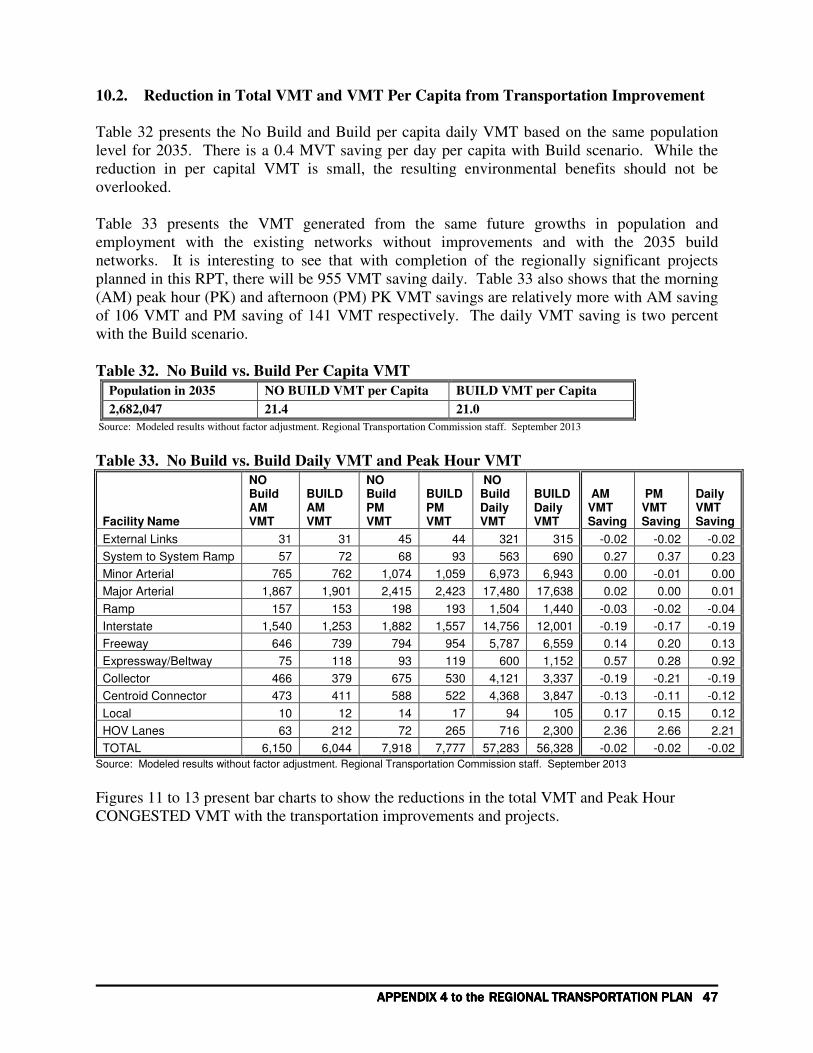
APPENDIX APPENDIX APPENDIX APPENDIX 4444 to the to the to the to the REGIONAL TRANSPORTATION PLAN REGIONAL TRANSPORTATION PLAN REGIONAL TRANSPORTATION PLAN REGIONAL TRANSPORTATION PLAN 47474747
10.2. Reduction in Total VMT and VMT Per Capita from Transportation Improvement
Table 32 presents the No Build and Build per capita daily VMT based on the same population
level for 2035. There is a 0.4 MVT saving per day per capita with Build scenario. While the
reduction in per capital VMT is small, the resulting environmental benefits should not be
overlooked.
Table 33 presents the VMT generated from the same future growths in population and
employment with the existing networks without improvements and with the 2035 build
networks. It is interesting to see that with completion of the regionally significant projects
planned in this RPT, there will be 955 VMT saving daily. Table 33 also shows that the morning
(AM) peak hour (PK) and afternoon (PM) PK VMT savings are relatively more with AM saving
of 106 VMT and PM saving of 141 VMT respectively. The daily VMT saving is two percent
with the Build scenario.
Table 32. No Build vs. Build Per Capita VMT
Population in 2035 NO BUILD VMT per Capita BUILD VMT per Capita
2,682,047 21.4 21.0
Source: Modeled results without factor adjustment. Regional Transportation Commission staff. September 2013
Table 33. No Build vs. Build Daily VMT and Peak Hour VMT
Facility Name
NO Build AM VMT
BUILD AM VMT
NO Build PM VMT
BUILD PM VMT
NO Build Daily VMT
BUILD Daily VMT
AM VMT Saving
PM VMT Saving
Daily VMT Saving
External Links 31 31 45 44 321 315 -0.02 -0.02 -0.02
System to System Ramp 57 72 68 93 563 690 0.27 0.37 0.23
Minor Arterial 765 762 1,074 1,059 6,973 6,943 0.00 -0.01 0.00
Major Arterial 1,867 1,901 2,415 2,423 17,480 17,638 0.02 0.00 0.01
Ramp 157 153 198 193 1,504 1,440 -0.03 -0.02 -0.04
Interstate 1,540 1,253 1,882 1,557 14,756 12,001 -0.19 -0.17 -0.19
Freeway 646 739 794 954 5,787 6,559 0.14 0.20 0.13
Expressway/Beltway 75 118 93 119 600 1,152 0.57 0.28 0.92
Collector 466 379 675 530 4,121 3,337 -0.19 -0.21 -0.19
Centroid Connector 473 411 588 522 4,368 3,847 -0.13 -0.11 -0.12
Local 10 12 14 17 94 105 0.17 0.15 0.12
HOV Lanes 63 212 72 265 716 2,300 2.36 2.66 2.21
TOTAL 6,150 6,044 7,918 7,777 57,283 56,328 -0.02 -0.02 -0.02
Source: Modeled results without factor adjustment. Regional Transportation Commission staff. September 2013 Figures 11 to 13 present bar charts to show the reductions in the total VMT and Peak Hour
CONGESTED VMT with the transportation improvements and projects.

48484848 REGIONAL TRANSPORTATION COMMISSION OF SOUTHERN NEVADAREGIONAL TRANSPORTATION COMMISSION OF SOUTHERN NEVADAREGIONAL TRANSPORTATION COMMISSION OF SOUTHERN NEVADAREGIONAL TRANSPORTATION COMMISSION OF SOUTHERN NEVADA
Figure 11.
No Build Vs. 2035 Build Networks
0
2,000
4,000
6,000
8,000
10,000
12,000
Exter
nal L
inks
Syste
m to
Sys
tem
Ram
p
Minor
Arte
rial
Major
Arte
rial
Ram
p
Inte
rstate
Freew
ay
Expre
ssway/
Beltway
Colle
ctor
Centro
id C
onne
ctor
Loca
l
HO
V Lan
es
Total
Facility Type
Mile
s
NO Build Link Miles
Build Link Miles
NO Build Lane Miles
Build Lane Miles
Source: Regional Transportation Commission staff. September 2013 Figure 12.
2035 No Build Vs. Build VMT
0
10,000
20,000
30,000
40,000
50,000
60,000
Facility Type
VM
T in
Th
ou
sa
nd
NO Build AM VMT
BUILD AM VMT
NO Build PM VMT
BUILD PM VMT
NO Build Daily VMT
BUILD Daily VMT
Source: Regional Transportation Commission staff. September 2013

APPENDIX APPENDIX APPENDIX APPENDIX 4444 to the to the to the to the REGIONAL TRANSPORTATION PLAN REGIONAL TRANSPORTATION PLAN REGIONAL TRANSPORTATION PLAN REGIONAL TRANSPORTATION PLAN 49494949
Figure 13. PK Hour Congested VMT
No-Build Vs. Build PK Period Congested VMT
0
2,000
4,000
6,000
8,000
10,000
12,000
14,000
Sys
tem to
Sys
tem
Ram
p
Minor
Arte
rial
Major
Arte
rial
Ram
p
Inte
rstate
Freew
ay
Colle
ctor
HO
V Lan
es
Total
Facility Type
VM
T i
n H
un
dre
ds
NO BUILD CongestAM VMT
BUILD Congest AMVMT
NO BUILD CongestPM VMTBUILD Congest PMVMT
Source: Regional Transportation Commission staff. September 2013 10.3. Travel Time Savings Due to the Transportation Improvements
10.3.1. Average System Travel Time Savings by Trip Purpose
Table 34 presents the changes between the No Build and Build scenarios.
Table 34. Average Travel Distance and Travel Time Savings from Build Scenario Trip Purpose Distance Time Trips
Home-Based Work Income Group 1 0.00 -2.2 0
Home-Based Work Income Group 2 -0.05 -2.9 0
Home-Based Work Income Group 3 -0.09 -3.3 0
Home-Based Work Income Group 4 -0.08 -3.8 0
Home-Based School 0.00 -1.6 0
Home-Based Shopping 0.00 -1.5 0
Home-Based Other -0.02 -1.9 0
Non-Home-Based -0.14 -2.0 0
Hotel-Based Convention 0.09 -1.0 0
Hotel-Based Gaming 0.22 -0.6 0
Visitor Hotel-Based Other 0.20 -0.7 0
Visitor Non-Hotel-Based Other 0.15 -0.3 0
Non-Hotel Gaming 0.33 -0.3 0
Visitor Airport 4.24 -9.0 41,636
Resident Airport 3.31 -10.7 0
Airport-Based Business 5.08 -7.7 0
Airport-Based Other 4.26 -9.0 0
Non-Airport-Based Business 0.50 -0.4 0
Non-Airport-Based Other 0.33 -0.3 0
Source: Modeled Data. Regional Transportation Commission staff. September 2013

50505050 REGIONAL TRANSPORTATION COMMISSION OF SOUTHERN NEVADAREGIONAL TRANSPORTATION COMMISSION OF SOUTHERN NEVADAREGIONAL TRANSPORTATION COMMISSION OF SOUTHERN NEVADAREGIONAL TRANSPORTATION COMMISSION OF SOUTHERN NEVADA
Chart A from Table 35.Transportation Improvement Caused Changes in Average Travel
Distance by Trip Purpose
System Average Distance change
-1.00
0.00
1.00
2.00
3.00
4.00
5.00
6.00
Hom
e-Base
d W
ork In
com
e G
roup
1
Hom
e-Base
d W
ork In
com
e G
roup
2
Hom
e-Base
d W
ork In
com
e G
roup
3
Hom
e-Base
d W
ork In
com
e G
roup
4
Hom
e-Base
d Sch
ool
Hom
e-Base
d Sho
ppin
g
Hom
e-Base
d O
ther
Non
-Hom
e-Bas
ed
Hot
el-B
ased
Con
ventio
n
Hot
el-B
ased
Gam
ing
Visito
r Hot
el-B
ased
Oth
er
Visito
r Non
-Hote
l-Bas
ed O
ther
Non
-Hot
el G
aming
Visito
r Airp
ort
Res
iden
t Airp
ort
Airpor
t-Base
d Bus
ines
s
Airpor
t-Base
d O
ther
Non
-Airp
ort-Bas
ed B
usin
ess
Non
-Airp
ort-Bas
ed O
ther
Trip Purpose
Dis
tan
ce C
han
ge i
n M
ile
Distance
Source: Modeled Data. Regional Transportation Commission staff. September 2013
Chart B from Table 35. Transportation Improvement Caused Changes in Average Travel
Time by Trip Purpose
Average Travel Time Saving from Transportation Improvement
0.0
2.0
4.0
6.0
8.0
10.0
12.0
Hom
e-Base
d W
ork In
com
e G
roup
1
Hom
e-Base
d W
ork In
com
e G
roup
2
Hom
e-Base
d W
ork In
com
e G
roup
3
Hom
e-Base
d W
ork In
com
e G
roup
4
Hom
e-Base
d Sch
ool
Hom
e-Base
d Sho
ppin
g
Hom
e-Base
d O
ther
Non
-Hom
e-Bas
ed
Hot
el-B
ased
Con
ventio
n
Hot
el-B
ased
Gam
ing
Visito
r Hot
el-B
ased
Oth
er
Visito
r Non
-Hote
l-Bas
ed O
ther
Non
-Hot
el G
aming
Visito
r Airp
ort
Res
iden
t Airp
ort
Airpor
t-Base
d Bus
ines
s
Airpor
t-Base
d O
ther
Non
-Airp
ort-Bas
ed B
usin
ess
Non
-Airp
ort-Bas
ed O
ther
Trip Purpose
Tim
e S
avin
g in
Min
ute
Time Saved
Source: Modeled Data. Regional Transportation Commission staff. September 2013
In Table 34, the modeled system average travel distance by trip purpose and average travel time
by trip purpose are used in the calculation. The above two charts provide visual presentations of

APPENDIX APPENDIX APPENDIX APPENDIX 4444 to the to the to the to the REGIONAL TRANSPORTATION PLAN REGIONAL TRANSPORTATION PLAN REGIONAL TRANSPORTATION PLAN REGIONAL TRANSPORTATION PLAN 51515151
the changes in average travel distance by trip purpose and average travel time by trip purpose.
Note that because of the opening of the SNSA, the airport travel distances increase in the Build
scenario.
10.3.2. Travel Time Savings from TAZ to TAZ
Figures 14A to 14B on the next two pages provide graphic presentations of the travel time
improved from Build scenarios over No Build scenarios. The contour maps show the travel time
from all TAZs to TAZ 528 where the County Building resides by 5 minute intervals.
The contour maps by 5 minute intervals in Figures 15A to 15B show the travel time from all
TAZs to TAZ 687 that is the core area of the Strip and the intersection of Las Vegas Blvd and
Flamingo locates in the TAZ 687.
10.4. Link Travel Volumes Over Road Capacity
Figures 16A and 16B depict the traffic volume to capacity ratios for No Build and Build
Scenarios for the whole RTC travel demand modeling area. The ratios are calculated by using
modeled traffic volumes for peak hours (morning or evening peak hours, whichever is higher)
and roadway peak hour capacities. Figure 16B shows that the congestion areas and severe level
in the Build Scenario are much improved than that in the No Build scenario mapped in Figure
16A.

52525252 REGIONAL TRANSPORTATION COMMISSION OF SOUTHERN NEVADAREGIONAL TRANSPORTATION COMMISSION OF SOUTHERN NEVADAREGIONAL TRANSPORTATION COMMISSION OF SOUTHERN NEVADAREGIONAL TRANSPORTATION COMMISSION OF SOUTHERN NEVADA
Figure 14A. No Build Scenario—Modeled 2035 Demand with Existing Networks: Auto
Time From All TAZs to TAZ 528 (County Building is located in TAZ 528)
Source: Regional Transportation Commission. September 2013

APPENDIX APPENDIX APPENDIX APPENDIX 4444 to the to the to the to the REGIONAL TRANSPORTATION PLAN REGIONAL TRANSPORTATION PLAN REGIONAL TRANSPORTATION PLAN REGIONAL TRANSPORTATION PLAN 53535353
Figure 14B. Build Scenario—Modeled 2035 Demand with 2035 Networks: Auto Time From
All TAZs to TAZ 528 (County Building is located in TAZ 528)
Source: Regional Transportation Commission. September 2013

54545454 REGIONAL TRANSPORTATION COMMISSION OF SOUTHERN NEVADAREGIONAL TRANSPORTATION COMMISSION OF SOUTHERN NEVADAREGIONAL TRANSPORTATION COMMISSION OF SOUTHERN NEVADAREGIONAL TRANSPORTATION COMMISSION OF SOUTHERN NEVADA
Figure 15A. No Build Scenario—Modeled 2035 Demand with Existing Networks: Auto
Time From All TAZs to TAZ 687 (Las Vegas @ Flammingo)
Source: Regional Transportation Commission. September 2013

APPENDIX APPENDIX APPENDIX APPENDIX 4444 to the to the to the to the REGIONAL TRANSPORTATION PLAN REGIONAL TRANSPORTATION PLAN REGIONAL TRANSPORTATION PLAN REGIONAL TRANSPORTATION PLAN 55555555
Figure 15B. Build Scenario—Modeled 2035 Demand with 2035 Networks: Auto Time From
All TAZs to TAZ 687 (Las Vegas @ Flamingo)
Source: Regional Transportation Commission. September 2013
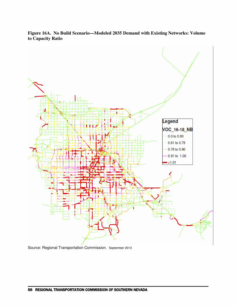
56565656 REGIONAL TRANSPORTATION COMMISSION OF SOUTHERN NEVADAREGIONAL TRANSPORTATION COMMISSION OF SOUTHERN NEVADAREGIONAL TRANSPORTATION COMMISSION OF SOUTHERN NEVADAREGIONAL TRANSPORTATION COMMISSION OF SOUTHERN NEVADA
Figure 16A. No Build Scenario—Modeled 2035 Demand with Existing Networks: Volume
to Capacity Ratio
Source: Regional Transportation Commission. September 2013

APPENDIX APPENDIX APPENDIX APPENDIX 4444 to the to the to the to the REGIONAL TRANSPORTATION PLAN REGIONAL TRANSPORTATION PLAN REGIONAL TRANSPORTATION PLAN REGIONAL TRANSPORTATION PLAN 57575757
Figure 16B. Build Scenario—Modeled 2035 Demand with 2035 Networks: Volume to
Capacity Ratio
Source: Regional Transportation Commission. September 2013

58585858 REGIONAL TRANSPORTATION COMMISSION OF SOUTHERN NEVADAREGIONAL TRANSPORTATION COMMISSION OF SOUTHERN NEVADAREGIONAL TRANSPORTATION COMMISSION OF SOUTHERN NEVADAREGIONAL TRANSPORTATION COMMISSION OF SOUTHERN NEVADA
APPENDIX 4-A: RTC 2009 Regional Travel Demand
Model
Prepared for:
Regional Transportation Commission
of Southern Nevada