appendix 3.1 drainage strategy - energy isles · check dams will facilitate the settlement of...
TRANSCRIPT
ENERGY ISLES WIND FARM i APPENDIX 3.1
Appendix 3.1 Drainage Strategy

ENERGY ISLES WIND FARM 2 APPENDIX 3.1
This page is intentionally blank.

ENERGY ISLES WIND FARM DRAINAGE STRATEGY
STATKRAFT
MARCH 2019


Prepared By:
Arcus Consultancy Services
7th Floor 144 West George Street
Glasgow G2 2HG
T +44 (0)141 221 9997 l E [email protected]
w www.arcusconsulting.co.uk
Registered in England & Wales No. 5644976

Drainage Strategy Energy Isles Wind Farm
Statkraft Arcus Consultancy Services March 2019 Page i
TABLE OF CONTENTS
1 INTRODUCTION ........................................................................................................ 1
1.1 Preparation of the Drainage Strategy ............................................................ 1
2 THE MANAGEMENT OF SURFACE WATERS ................................................................ 1
2.1 Location of Silt Traps and Silt Fencing ........................................................... 1
2.2 Location of Cut-off Ditches ............................................................................ 2
2.3 Location of Check Dams ................................................................................. 2
2.4 Location of Straw Bales and Semi-Permeable Obstructions .......................... 3
2.5 Location of Settlement Lagoons ..................................................................... 3
2.6 Outflow monitoring from Settlement Lagoons .............................................. 3
2.7 Provision for Storm Events ............................................................................. 3
2.8 Trackside Drainage ......................................................................................... 3
2.9 Site Drainage and Protection of Wetland Habitats ........................................ 4
3 THE MANAGEMENT AND MOVEMENT OF FRESH CONCRETE ..................................... 5
3.1 Concrete Batching .......................................................................................... 5
3.2 Accidental Spillage Within Borrow Pits .......................................................... 5
3.3 Accidental Spillage Outside Borrow Pits ........................................................ 5
3.4 Vehicle Washing ............................................................................................. 5
4 FOUL DRAINAGE ........................................................................................................ 5
5 HYDROCARBON CONTAMINATION ........................................................................... 5
5.1 Vehicle Maintenance ...................................................................................... 5
5.2 Chemical Storage ........................................................................................... 6
6 CONSTRUCTION OF CULVERTS AND BRIDGES ......................................................... 6
6.1 Protection of Watercourse Crossing............................................................... 7
7 BORROW PIT OPENING AND DRAINAGE .................................................................. 7
7.1 Management of surface water ....................................................................... 8
7.2 Loose Track Material ...................................................................................... 8
7.3 Material excavated during track construction ............................................... 8
7.4 Handling of Peat ............................................................................................. 8
7.5 Measures to Protect GWDTES ........................................................................ 9
8 CONSTRUCTION OF TURBINE BASES NEAR WATERCOURSES .................................. 9
Drainage Strategy Energy Isles Wind Farm
Arcus Consultancy Services Statkraft Page ii March 2019
9 PLATES .................................................................................................................... 11
Drainage Strategy Energy Isles Wind Farm
Statkraft Arcus Consultancy Services March 2019 Page 1
1 INTRODUCTION
1.1 Preparation of the Drainage Strategy
This Drainage Strategy has been prepared by Arcus Consultancy Services Ltd. (Arcus) at the request of Statkraft. The Drainage Strategy presented in this document is intended to demonstrate measures that could be used across the Development site to adequately protect hydrological and related resources. Detailed proposals for such measures will be documented prior to construction, and will provide the same or greater protection for the water environment as those described in this document. The measures are proportionate to the risk and, where greater risk is highlighted at specific locations prior to construction, specific measures would be agreed for those locations.
The methods set out in the Drainage Strategy are based on good practise and the following guidance:
• The Construction Industry Research and Information Association (CIRIA) (2015), Environmental Good Practice on Site (C741)1;
• CIRIA, ‘Control of Water Pollution from Construction Sites (C532)’ (2001);
• Groundwater protection policy for Scotland V3, (2009)2;
• SNH’s “Good Practice During Wind Farm Construction”, (2015)3;
• SEPA’s Prevention of Pollution from Civil Engineering Contracts: Special Requirements publication (SEPA, 2006)4;
• Engineering in the water environment: good practise guide, River Crossings, (SEPA, 2010);
• Scottish Natural Heritage (SNH) (2015), Good Practice During Wind Farm Construction5;
• Culverting of Water courses: Position Statement and Supporting Guidance, (SEPA, 2011);
• GPP4: Treatment and disposal of wastewater where there is no connection to the public foul sewer (October 2017); and
• GPP5: Works and maintenance in or near water (January 2017).
2 THE MANAGEMENT OF SURFACE WATERS
2.1 Location of Silt Traps and Silt Fencing
Silt traps and fences will be utilised, where required, to trap and filter sediment laden run-off from excavation works at the Development, including turbine bases and access roads. Silt traps will be formed by excavating across a waterway or low drainage area to allow sediment to settle out during infiltration. Silt traps or fences will be installed on the down-slope side of tracks within a drainage trench or ditch but will be sited to avoid slopes with
1 The Construction Industry Research and Information Association (CIRIA) (2015) Environmental Good Practice on Site Guide
(C741), CIRIA: London. 2 Groundwater Protection Policy for Scotland V3, 2009. [online] Available at: https://www.sepa.org.uk/media/34371/groundwater-protection-policy-for-scotland-v3-november-2009.pdf 3 Joint Publication by Scottish Renewables, Scottish Natural Heritage, Scottish Environmental Protection Agency, Forestry Commission Scotland and Historic Scotland, 2015. Good Practice during Wind Farm Construction. 4 SEPA, 2006. Prevention of Pollution from Civil Engineering Contracts: Special Requirements. Version 2, June 2006. 5 SNH (2015b) Good practice during windfarm construction, 3rd Edition [Online] Available at:
http://www.snh.gov.uk/docs/A1168678.pdf (Accessed 08/01/2018)
Drainage Strategy Energy Isles Wind Farm
Arcus Consultancy Services Statkraft Page 2 March 2019
a gradient greater than 1 in 20 to ensure sediment is not transferred into the wider hydrological system and specifically to groundwater.
Silt Fences may be placed at the outfall of the settlement lagoons to filter sediment during times of heavy rainfall. They can also be utilised as perimeter controls, particularly at the lower or down slope edge of a disturbed area or around perimeter of a stockpile area. The silt fence must be trenched on the uphill side and stakes must be installed on the downhill side.
SEPA will be consulted prior to construction regarding the placement of silt traps adjacent to watercourses.
Typical silt fencing and silt trap examples are shown in Plate 9.1 and Plate 9.2.
2.2 Location of Cut-off Ditches
Clean water diversions (pre earthworks drainage) are used to minimise water quality degradation by keeping clean water away from active construction activities. Clean water (non-contaminated water from on-site disturbances) should be kept separate from potentially contaminated water.
Where applicable, diversion drainage measures (cut-off ditches) will be installed to divert clean water run off away from areas disturbed by construction in advance of excavations. This will reduce the flow of water onto exposed soils and rock, resulting in a reduction of potential clean water with a high silt content requiring treatment when departing excavations.
A clean water cut-off ditch should be installed on the upslope of borrow pits and should shed to vegetated ground.
A dirty water cut-off ditch should be installed below the toe of borrow pits and should shed to vegetated ground following treatment via silt traps and settlement ponds.
Should there be a requirement for dewatering, water from dewatering of excavations shall be pumped via surface silt traps to ensure that sediment does not enter surrounding watercourses or clean water drains.
Cut-off ditches should be discharged into areas of vegetation for dispersion or infiltration. Silt traps, or other forms of mitigation, may be required at the outfall of diversions to assist in the prevention of scouring and the remobilisation of silt deposits. Vegetated areas used for discharge will be selected by the ECoW and Contractor’s Site Environmental Manager to reduce any potential negative effects on habitats.
Cut-off ditch discharge points will be a minimum of 50 m from any watercourse or drainage network, to allow infiltration or the settling of suspended sediments.
2.3 Location of Check Dams
Check dams will be installed within drainage ditches at regular intervals, where appropriate.
Check dams will facilitate the settlement of suspended solids by slowing the flow of water within the drainage ditches reducing scour and channel erosion. Appropriately sized stone pitching will be used within the dam in order to provide a rough surface for water within the drainage ditch to pass over.
Check dams should be installed on gradients of less than 1 in 3, as outlined in the SuDS Manual.
Plate 9.3 of this document shows a typical check dam.

Drainage Strategy Energy Isles Wind Farm
Statkraft Arcus Consultancy Services March 2019 Page 3
2.4 Location of Straw Bales and Semi-Permeable Obstructions
Hessian-wrapped straw bales or semi-permeable obstructions will be implemented in conjunction with silt fencing to filter out coarse sediment. Stockpiles of material should be monitored during rainfall events and straw bales should be implemented if there is potential for leaching to surface watercourses. Straw bales should be assessed after heavy rainfall events and should be replaced if the straw bale has degraded.
To ensure the straw bales are working adequately, there should be no gaps between placed bales and they should be staked and entrenched into the ground.
Plate 9.4 of this document shows a typical straw bale arrangement.
2.5 Location of Settlement Lagoons
Settlement lagoons will be implemented where topography is appropriate where large excavation works dictate and in areas where the level of runoff is likely to exceed levels normally contained within a silt trap.
All settlement lagoons will be actively managed to control water levels and ensure that any runoff is contained, especially during times of rainfall. If required to achieve the necessary quality of the final run-off, further measures could include the use of flocculent to further facilitate the settlement of suspended solids.
An overview map of drainage at the site is shown on Figure 3219-DR-P-0044 while more detailed locations of typical drainage measures at infrastructure is illustrated on Figures 3219-DR-P-45 to 32191-DR-P-50 included in Appendix A.
2.6 Outflow monitoring from Settlement Lagoons
Settlement lagoon outflow will be regularly inspected and discharge may be pumped, when required, for maintenance purposes. Any pumping activities will be supervised and authorised by the Contractor’s Site Manager and the project Ecological Clerk of Works (ECoW) or Hydrological Clerk of Works (HCoW).
Treated water will be discharged onto vegetated surfaces and directed away from surface watercourses. Within all the catchments, irrigation techniques, which may include the use of perforated discharge hoses, or similar, will be employed to rapidly distribute discharge across a vegetated slope. These works will be carried out in consultation with the ECoW.
2.7 Provision for Storm Events
Temporary storage volume for storm run-off from the turbine foundations and crane hardstanding areas would be provided via settlement lagoons.
Where access tracks are in cut or fill, drainage channels installed on the down slope would shed track run-off to adjacent rough ground approximately every 30 m, to attenuate flow and allow natural filtration to remove sediments. In areas within 35 m of a primary water or where cross-slopes exceed 1 in 20, drainage channels will be bunded and outflow will be monitored daily. Appropriate licensing and discharge consents will be sought (under Water Environment (Controlled Activities) (Scotland) Regulations 2011 (CAR)) before the construction phase of the Development.
2.8 Trackside Drainage
In areas where the peat is shallow i.e. less than approximately 1.0 m in depth, the road formation will be created by a cut (and fill) operation. A lateral drain will be established on the uphill side of the road to drain water from the slopes and cross drains will be established at regular intervals as determined by site conditions.
Drainage Strategy Energy Isles Wind Farm
Arcus Consultancy Services Statkraft Page 4 March 2019
Peat and topsoil, where present, will be stored beside the road for use in re-instatement of road shoulders. Consideration will be given to the potential for entrapment of snow and water in their placement.
Where the peat layer is of 1.0 m thickness or more and where the side slope is significant or where failure of the peat could result in landslip, the peat will be removed down to rockhead or suitable sub-soil horizon, leaving batters on each side with angles sufficient to ensure stability of the peat batter. Similarly, for excavations less than 1.0 m, but where the local gradient gives concern (1:10 or greater) with regards to the stability of the peat, then suitable slopes shall be cut back to ensure the peat batter is stable.
A double ditch will be established uphill of the batter to avoid significant water flow over it, thereby minimising erosion. The running surface of the road will have a cross fall in order to drain run-off into the ditches. A lateral drain will be made on the uphill side of the road with cross drainpipes at appropriate locations (where ground conditions are wet, cross-drains will be installed every 30 m along the road to maintain hydrological flow). The diameter of the cross drains will be calculated taking account of the catchment for each pipe. A ditch will be constructed on the low side of the track as necessary. The outlet of the drain will be at appropriate locations, with hessian/copra mats placed at the outfalls (where appropriate) in order to minimise erosion during periods of heavy rainfall or snow melt.
2.9 Site Drainage and Protection of Wetland Habitats
Site drainage will be designed to ensure that hydraulic connectivity of wetland habitats (in particular potential Groundwater Dependent Terrestrial Ecosystems (GWDTEs)) is maintained. The site drainage design will be designed and implemented by the Contractor following approval from the site ECoW, and SEPA where necessary.
Although it is considered unlikely that the Development will directly impact potential GWDTEs, there is a possibility that changes in ground conditions have occurred since the baseline surveys were undertaken and that previously unrecorded wetland habitats or potential GWDTEs may be identified during construction. To ensure implementation of best working practices and to minimise construction related impacts to potential GWDTEs and the wider aquatic environment, the following mitigation measures will be adopted:
• The ECoW will undertake a pre-works survey for potential GWDTEs along the working corridor prior to commencement of works. The ECoW will demarcate any potential GWDTEs or wetland habitats with the aim of micrositing to avoid direct impacts;
• Site drainage design will take existing wet ground conditions into account; • Where wetland habitats cannot be avoided, measures will be put in place to ensure
hydrological connectivity is maintained; therefore minimising impacts to potential GWDTEs and wetland habitats. Such measures will be designed in agreement with SEPA and will include installation of cross-drains, drainage matting or construction of floating roads where deemed appropriate. Ground conditions and land topography will be taken into consideration when designing suitable mitigation measures;
• Drainage will be designed to discharge clean water from the upslope drainage ditch approximately every 30 m. This will ensure surface water connectivity is maintained as well as ensuring there is no scouring of the drainage ditch;
• Surface run-off from the track will be discharged every 30 m following suitable treatment;
• Where dewatering of turbine foundations is required, water will be re-distributed over vegetated surfaces near excavations, following necessary treatment. This will ensure there is no net loss of water quantity or quality from the overall hydrological system; and,
• De-watering events will be temporary and typically only a few weeks in duration
Drainage Strategy Energy Isles Wind Farm
Statkraft Arcus Consultancy Services March 2019 Page 5
3 THE MANAGEMENT AND MOVEMENT OF FRESH CONCRETE
3.1 Concrete Batching
Concrete batching is likely to be carried out on-site rather than being imported to the site ready-mixed. Concrete batching will be conducted within bunded areas of the borrow pits and this area will be underlain by an impermeable ground membrane layer. The bund will have a 110% capacity to attenuate stored liquids (including fresh concrete). This will reduce the potential for accidental spillages to contaminate surface water or ground water.
3.2 Accidental Spillage Within Borrow Pits
An appropriately sized spill kit(s) will be provided and maintained on site. This will contain materials, such as absorbent granules and pads, absorbent booms and collection bags. These are designed to halt the spread of spillages and will be deployed as necessary, should a spillage occur elsewhere.
3.3 Accidental Spillage Outside Borrow Pits
Speed limits for vehicles transporting concrete will be set at a maximum of 15 miles per hour (mph) and will be continually monitored by the project manager of the infrastructure contractor. Maximum vehicle load capacities will not be exceeded. Although tracks will be maintained in good condition, vehicle loads will be reduced when a rougher surface is identified prior to track maintenance.
Measures to manage fresh concrete during pouring operations are described in Section 9: Construction of Turbine Bases near Watercourses.
3.4 Vehicle Washing
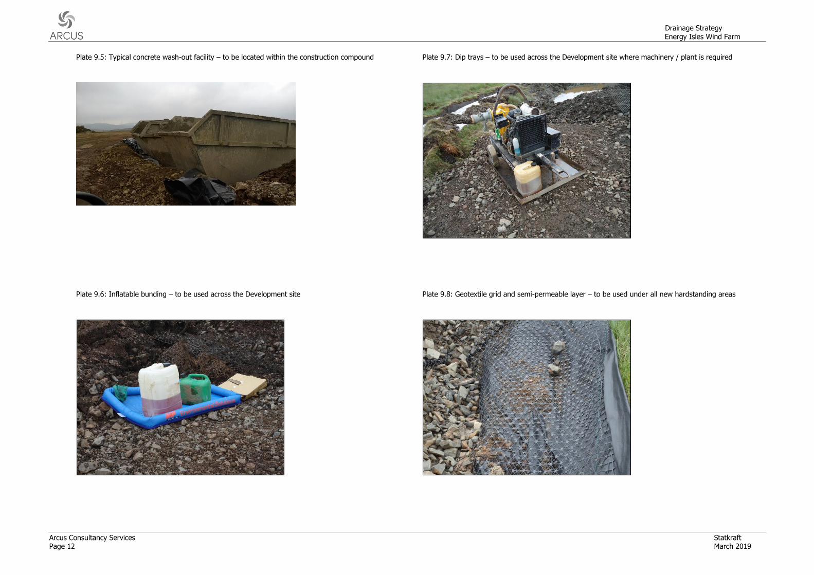
Should a batching plant utilised there will be a wash-out facility consisting of a sump overlain with a geosynthetic membrane. The geosynthetic membrane will filter out the concrete fines leaving clean water to pass through to the sump. The sump water either will be pumped to a licenced carrier and taken off site for approved disposal or, it will be discharged to surrounding vegetated surfaces where such discharge meets the requirements of SNH and SEPA and following consultation within the ECoW. This ‘soakaway’ type design allows the water to dissipate and the cement to hydrate. The resulting dry waste is inert and can therefore be used within the rockfill during road construction. No washing of concrete-associated vehicles will be undertaken outside the wash out facility, and the area will be signposted with all site contractors informed of the locations. The frequency of concrete plant washout may also be reduced through the use of retarders.
Plate 9.5 of this document displays a typical concrete wash-out facility.
Should batching plant facilities not be utilised across the site, vehicle washing should be undertaken within a designated wash area in the construction compound.
4 FOUL DRAINAGE
Effluent and waste from onsite construction personnel will be treated at a package sewage treatment plant or a septic tank and discharge into a properly designed and sized drainage field, in accordance with PPG4. The system will be designed for approval by SEPA prior to the construction phase of the Development.
5 HYDROCARBON CONTAMINATION
5.1 Vehicle Maintenance
During construction, contractors’ plant and machinery will be regularly maintained to ensure that there is minimal potential for fuel or oil leaks / spillages to occur. All
Drainage Strategy Energy Isles Wind Farm
Arcus Consultancy Services Statkraft Page 6 March 2019
maintenance will be conducted on suitable absorbent spill pads to minimise the potential for groundwater and surface water pollution. All machinery will be equipped with drip pans to contain minor fuel spillage or equipment leakages.
Plates 9.6 and 9.7 of this document display examples of dip pans and bunds.
5.2 Chemical Storage
Potentially contaminating chemicals stored on site will be kept within a secure bunded area to prevent any accidental spills from affecting hydrological resources. The bunded area will be within the construction compound and will be underlain by an impermeable ground membrane layer to reduce the potential pathways for contaminants to enter watercourses and groundwater.
Chemicals should be stored in a designated area, secured and locked to prevent theft or vandalism. A safe system for accessing the storage area would be implemented by the Construction Contractor.
6 CONSTRUCTION OF CULVERTS AND BRIDGES
The use of in-situ fresh concrete in the construction of watercourse crossings will be avoided where possible by the use of pre-cast elements. All existing culverts will be upgraded and anticipated to be replaced with suitable pre-cast culvert designs. Ready-made concrete ‘box style’ or wide, circular concrete or plastic culverts will be used.
Prior to access track construction, site operatives will identify flush areas, depressions or zones which may concentrate water flow. These sections will be spanned with plastic pipes or drainage matting to ensure hydraulic conductivity under the road, and reduce water flow over the road surface during heavy precipitation.
Culverts will be designed based on best practice6,7 in order to minimise effects of developments on the natural integrity and continuity of water courses. The design will incorporate the following criteria:
• Culverts will be well bedded to avoid settlement and protected by an adequate cover of road material;
• The substrate and side/ head walls will be reinforced in order to prevent erosion; • The culverts will be designed such that it does not cause a barrier to movement of
fish or other aquatic fauna; • Culvert floors will have the same gradient (not exceeding a slope of 3 %) and level,
and carry similar bed material and flow, as the original steam; • There shall be no hydraulic drop at the culvert inlet or outlet; • The width of the culvert will be greater than the active channel width of the
watercourse; • Culverts will be used to conduct water under the wind farm tracks and will likely be a
maximum of 5 m in length; • Any culvert over 5 m in length will be a bottomless arch culvert, and the natural
substrate of the watercourse will be maintained; • The top elevation of the culvert will be greater than the natural bank height of the
watercourse; • The height of the river bank is measured from the lowest point of the bed, excluding
any artificial heightening of the bank (e.g. embankments, retaining walls); and
6 Engineering in the water environment: good practise guide, River Crossings, SEPA, 2010. [online] Available at: https://www.sepa.org.uk/media/151036/wat-sg-25.pdf [Accessed 08/03/2019]. 7 Culverting of Water courses: Position Statement and Supporting Guidance, SEPA, 2011. [online] Available at: https://www.sepa.org.uk/media/150919/wat_ps_06_02.pdf [Accessed 08/03/2019].
Drainage Strategy Energy Isles Wind Farm
Statkraft Arcus Consultancy Services March 2019 Page 7
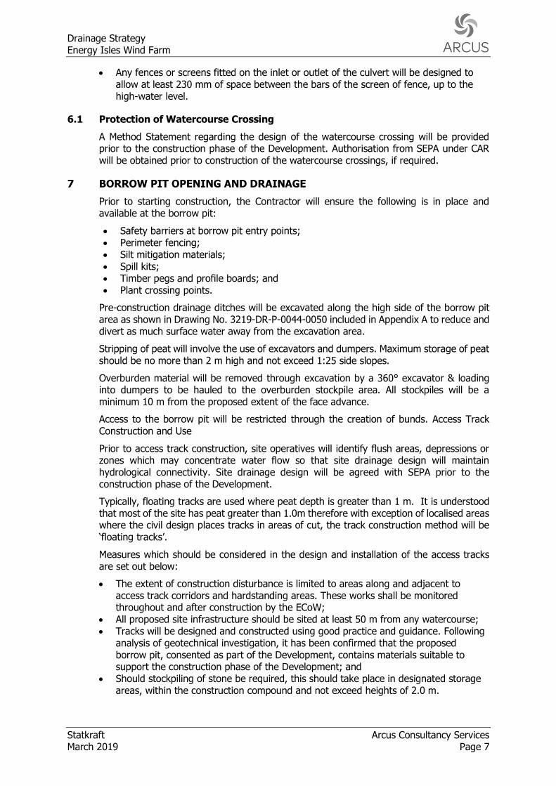
• Any fences or screens fitted on the inlet or outlet of the culvert will be designed to allow at least 230 mm of space between the bars of the screen of fence, up to the high-water level.
6.1 Protection of Watercourse Crossing
A Method Statement regarding the design of the watercourse crossing will be provided prior to the construction phase of the Development. Authorisation from SEPA under CAR will be obtained prior to construction of the watercourse crossings, if required.
7 BORROW PIT OPENING AND DRAINAGE
Prior to starting construction, the Contractor will ensure the following is in place and available at the borrow pit:
• Safety barriers at borrow pit entry points; • Perimeter fencing; • Silt mitigation materials; • Spill kits; • Timber pegs and profile boards; and • Plant crossing points.
Pre-construction drainage ditches will be excavated along the high side of the borrow pit area as shown in Drawing No. 3219-DR-P-0044-0050 included in Appendix A to reduce and divert as much surface water away from the excavation area.
Stripping of peat will involve the use of excavators and dumpers. Maximum storage of peat should be no more than 2 m high and not exceed 1:25 side slopes.
Overburden material will be removed through excavation by a 360° excavator & loading into dumpers to be hauled to the overburden stockpile area. All stockpiles will be a minimum 10 m from the proposed extent of the face advance.
Access to the borrow pit will be restricted through the creation of bunds. Access Track Construction and Use
Prior to access track construction, site operatives will identify flush areas, depressions or zones which may concentrate water flow so that site drainage design will maintain hydrological connectivity. Site drainage design will be agreed with SEPA prior to the construction phase of the Development.
Typically, floating tracks are used where peat depth is greater than 1 m. It is understood that most of the site has peat greater than 1.0m therefore with exception of localised areas where the civil design places tracks in areas of cut, the track construction method will be ‘floating tracks’.
Measures which should be considered in the design and installation of the access tracks are set out below:
• The extent of construction disturbance is limited to areas along and adjacent to access track corridors and hardstanding areas. These works shall be monitored throughout and after construction by the ECoW;
• All proposed site infrastructure should be sited at least 50 m from any watercourse; • Tracks will be designed and constructed using good practice and guidance. Following
analysis of geotechnical investigation, it has been confirmed that the proposed borrow pit, consented as part of the Development, contains materials suitable to support the construction phase of the Development; and
• Should stockpiling of stone be required, this should take place in designated storage areas, within the construction compound and not exceed heights of 2.0 m.

Drainage Strategy Energy Isles Wind Farm
Arcus Consultancy Services Statkraft Page 8 March 2019
7.1 Management of surface water
Access tracks will be designed to have adequate cross fall to avoid ponding of rainwater and surface run-off. Run-off from the access tracks and existing drainage ditches will be directed into ditches or trenches that will be designed to intercept, filtrate and convey the runoff.
Check dams will be installed within the swales and existing drainage ditches in order to increase the attenuation of run-off.
Permanent drainage ditches and trenches adjacent to access tracks will have outlets at specified intervals to reduce the volume of water collected in a single channel and, therefore, reduce the potential for erosion. Further measures could include the use of flocculent to further facilitate the settlement of suspended solids.
The appointed contractor would be responsible for the management of all surface water run-off, including the design and management of a drainage scheme compliant with SUDS principles. This may include settlement lagoons and retention ponds, incorporating natural or assisted attenuation.
Typical drainage details are illustrated on Figures 3219-DR-P-0050 and 0051 included in Appendix A.
7.2 Loose Track Material
Loose material from construction of access tracks will be prevented from entering watercourses by utilising the following measures:
• Silt fences will be erected between areas at risk of erosion and watercourses; • Silt fences and swales will be inspected daily and cleaned out as required to ensure
their continued effectiveness; • Silt matting will be checked daily and replaced as required; • Excess silt will be disposed of in designated areas at least 35 m away from any
watercourses or drainage ditches; • Culverts, swales and drains will be checked after periods of heavy precipitation; • The inlets and outlets of settlement lagoons, retention basins and extended detention
basins will be checked on a daily basis for blockages; and • The access tracks will be inspected on a daily basis for areas where water collects
and ponds.
An example of a semi-permeable geotextile layer and a geotextile grid is shown in Plate 9.8 of this document.
7.3 Material excavated during track construction
Material excavated during track construction will be stored adjacent to the track and compacted in order to limit instability and erosion potential. Peat will not be allowed to dry out and silt fences and mats will be employed to minimise sediment levels in run-off. Material will be stored at least 50 m from watercourses in order to reduce the potential from sediment to be transferred into the wider hydrological system.
Typical overburden stockpile measures are shown in Plate 9.9 of this document.
7.4 Handling of Peat
Handling of peat by the contractor should be undertaken with due care and in accordance with best practice. Suitable locations should be sited in areas of lower ecological value, low stability risk and at a suitable distance from water courses.
Drainage Strategy Energy Isles Wind Farm
Statkraft Arcus Consultancy Services March 2019 Page 9
Construction work should be managed as much as possible to avoid periods when peat materials are likely to be wetter i.e. high rainfall events. Details on peat management is covered within the Peat Management Plan.
7.5 Measures to Protect GWDTES
The following measures will ensure that water quality and the flow supply of groundwater and near-surface water are maintained during the construction and operational phase of the Development. Key measures include:
• Silt traps will be deployed to trap and filter sediment-laden run-off throughout the construction phase of the Development;
• Settlement lagoons will be constructed and actively managed to control water levels and ensure that any runoff is contained, especially during times of rainfall;
• Where wetland habitats cannot be avoided, measures will be put in place to ensure hydrological connectivity is maintained; therefore, minimising impacts to potential GWDTEs and wetland habitats. Such measures will be designed in agreement with SEPA and will include installation of cross-drains, drainage matting or construction of floating roads where deemed appropriate. Ground conditions and land topography will be taken into consideration when designing suitable mitigation measures;
• Site operatives will identify flush areas, depressions or zones which may concentrate water flow. Floating roads will be used in these areas to ensure hydraulic conductivity under the road, and reduce water flow over the road surface. Additionally, these sections will be spanned with plastic pipes or drainage matting to ensure hydraulic conductivity under the road. Drainage measures in the areas where floating roads will be employed will be mapped thoroughly in order to serve their purpose without affecting drainage patterns;
• Site drainage design will avoid any severance of saturated areas to ensure hydrological connectivity is maintained. Site drainage design will be agreed with SEPA prior to the construction phase of the Development;
• Turbine foundations will comprise large excavations in the ground that will be de-watered, and hence water flow is typically into the foundation area. This will prevent concrete leaching into groundwater or surface water in the event of shutter collapse;
• All excavations will be sufficiently dewatered before concrete pours begin and that dewatering continues while the concrete cures. However, construction good practice will be followed to ensure that fresh concrete is isolated from the dewatering system; and
• Water from dewatering activities will be treated by settlement lagoons and will be discharged onto vegetated surfaces, ensuring no net loss of water from the hydrological system. If ponding of water is observed during the discharge onto vegetated surfaces, additional measures such as the use of irrigation hoses will be employed.
8 CONSTRUCTION OF TURBINE BASES NEAR WATERCOURSES
Methods to protect surface and groundwater from the batching and transportation of concrete are considered in Section 3: The Management and Movement of Fresh Concrete.
To prevent pollution, it is important that all concrete pours are planned and that specific procedures are adopted where there may be a risk of surface water or groundwater contamination, in accordance with CIRIA C532. These procedures will include:
• Lining the foundation excavation with an impermeable geotextile membrane to ensure that any exposed bedrock is covered. This will limit the potential for concrete fines to enter groundwater via fissures in the bedrock.
Drainage Strategy Energy Isles Wind Farm
Arcus Consultancy Services Statkraft Page 10 March 2019
• An impermeable geotextile membrane will be placed around wooden shutter casings during concrete pouring. This will prevent concrete leaching into groundwater or surface water in the event of shutter collapse;
• Ensuring that all excavations are sufficiently dewatered before concrete pours begin and that dewatering continues while the concrete cures. However, construction good practice will be followed to ensure that fresh concrete is isolated from the dewatering system; and
• Ensuring that covers are available for freshly placed concrete to avoid the surface of the concrete washing away during heavy precipitation.
Typical foundation shuttering is shown in Plate 9.10 of this document.

Drainage Strategy Energy Isles Wind Farm
Statkraft Arcus Consultancy Services March 2019 Page 11
9 PLATES
Plate 9.1: Silt fencing – to be installed adjacent to access tracks in areas prone to erosion
Plate 9.3: Typical Check Dams
Plate 9.2: Typical silt trap – to be installed in drainage ditches adjacent to the access track Plate 9.4: Typical Straw Bale Arrangement
Drainage Strategy Energy Isles Wind Farm
Arcus Consultancy Services Statkraft Page 12 March 2019
Plate 9.5: Typical concrete wash-out facility – to be located within the construction compound
Plate 9.7: Dip trays – to be used across the Development site where machinery / plant is required
Plate 9.6: Inflatable bunding – to be used across the Development site
Plate 9.8: Geotextile grid and semi-permeable layer – to be used under all new hardstanding areas
Drainage Strategy Energy Isles Wind Farm
Statkraft Arcus Consultancy Services March 2019 Page 13
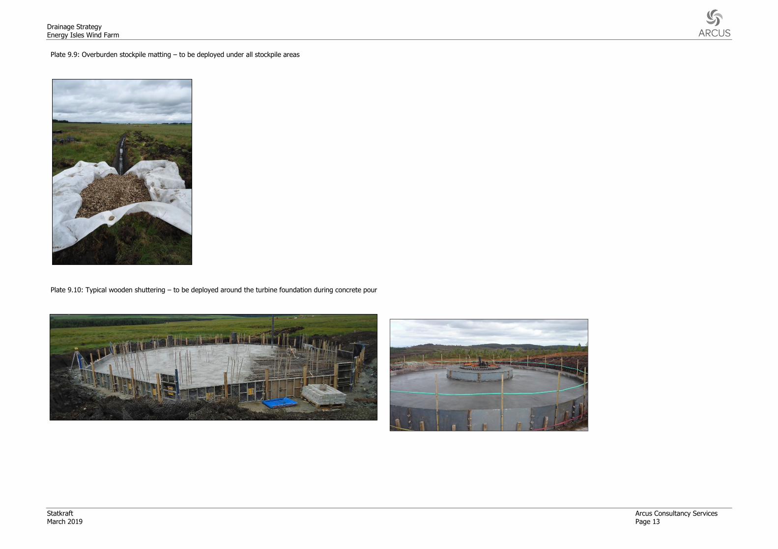
Plate 9.9: Overburden stockpile matting – to be deployed under all stockpile areas
Plate 9.10: Typical wooden shuttering – to be deployed around the turbine foundation during concrete pour

Drainage Strategy Energy Isles Wind Farm
Arcus Consultancy Services Statkraft Page 14 March 2019
APPENDIX A - FIGURES