appendix 3: equipment guide › globalassets › aisc › university... · plywood template for...
TRANSCRIPT

Appendix 3: Equipment Guide
This guide gives detailed instructions on how to use certain equipment provided for the competition. This document is not a comprehensive explanation of the competition rules and equipment. Instead, it is intended to highlight equipment that may be new to users.
The host school should review the guide in order to verify and test the equipment before the competition. The head judge should also review this guide in its entirety and share pertinent information with other judges.
Note that the Rules change from year to year. The photos are shown as examples, and bridges may not match the configuration shown for this year’s competition. If you experience a problem with your equipment, please contact AISC at [email protected] for a replacement.
www.aisc.org/ssbc 57

www.aisc.org/ssbc Equipment Guide 3-1
Pre-Construction
1. The judges should use thewood box for member checkto determine if each membermeets the requirement ofthe Rules Section 8.2.2.2.
The member should fitcomplete in the box.
Figure 1a. Wood box for member check.
Figure 1b. Judge has competitor peform member check.
2. Use the magnet to determine material compliance with the Rules.

www.aisc.org/ssbc Equipment Guide 3-2
Post-Construction
1. The judge should use theplywood template forground clearance todetermine if the bridgecomplies with Rules Section9.3.4.
Figure 1. Plywood template for ground clearance.
2. The judge should use theplywood template forpassageway to determine ifthe bridge complies withRules Section 9.3.9 and9.3.10.
Figure 2. Plywood template for ground clearance.
3. The judges should complete post construction checks including verification of otherdimensional requirements using provided equipment such as tape measures and steelbars.
Template must fit through the passageway for the entire span of the bridge
Template must fit under the bridge

www.aisc.org/ssbc Equipment Guide 3-3
Lateral Load Test
1. The judge may allow thecompetitors to preload thebridge. Place grating (notabs) on the bridge at thelocation along the spanindicated by Rules Section11.4 and the Lateral LoadTest Plan of the CompetitionRules.
Set three angles (75 lbs.total) over the stringerindicated in the Lateral LoadTest Plan of the CompetitionRules. Center the stack ofangles on the grating.
Figure 1. Lateral load test preload.
2. The judge should attach thelaser plumb-bob to thebridge stringer at thelocation labeled as “swaypoint” in the Lateral LoadTest Plan of the CompetitionRules.
The bottom of the laserplumb-bob should bepositioned about one to twoinches above the floorsurface. Loop any extra chainlength around the stringerand attach the hooked endso that the plumb-bob issecurely positioned at theappropriate height.
Figure 2a. Laser plumb-bob. Figure 2b. Chain secured.
Angles
Grating (no tabs)
Wrap extra chain
Secure hooked end Laser plumb-bob
Center angles on the grating in this direction

www.aisc.org/ssbc Equipment Guide 3-4
3. The judge should set up the lateral load stand. The final setup before loading is shown here. Position the lateral load stand so that rope runs perpendicular to the bridge stringer. The rope should run parallel to the floor. See Step 5 for how to adjust stand height. The rope should be taught before loading begins.
Figure 3. Lateral load stand setup
4. At the bridge end of the rope, connect the carabiner clip to the D-ring of the dog collar. Attach the dog collar to the bridge stringer as close to the laser plumb-bob as possible but at least one grating bar away from the laser plumb-bob so that the two items do not touch. The position of the dog collar and laser plumb-bob should be the same for each bridge. At the load stand end of the rope, connect the carabiner clip to the eye bolt with small plate.
Figure 4a. Rope to bridge. Figure 4b. Rope to eye bolt.
Rope lanyard
Dog collar
Rope runs parallel to the floor
Lanyard rope
Eye bolt with square plate
Lateral load stand
Dog collar
Eye bolt
Square plate
Carabiner
Rope
Carabiner
Laser plumb-bob chain
www.aisc.org/ssbc Equipment Guide 3-5
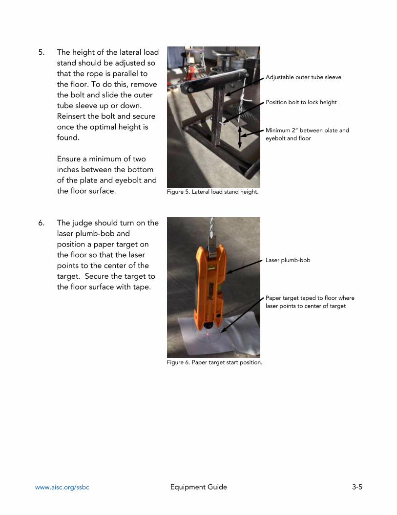
5. The height of the lateral loadstand should be adjusted sothat the rope is parallel tothe floor. To do this, removethe bolt and slide the outertube sleeve up or down.Reinsert the bolt and secureonce the optimal height isfound.
Ensure a minimum of twoinches between the bottomof the plate and eyebolt andthe floor surface. Figure 5. Lateral load stand height.
6. The judge should turn on thelaser plumb-bob andposition a paper target onthe floor so that the laserpoints to the center of thetarget. Secure the target tothe floor surface with tape.
Figure 6. Paper target start position.
Laser plumb-bob
Paper target taped to floor where laser points to center of target
Minimum 2” between plate and eyebolt and floor
Adjustable outer tube sleeve
Position bolt to lock height

www.aisc.org/ssbc Equipment Guide 3-6
7. To prevent slip at the foundation during the lateral load test, competitors may provide lateral restraint at the base of the structure at the floor level per Rules Section 11.4.1. Competitors may use a foot at each support or an object such as an angle. Do not apply restraint above the floor level. Do not push down on the bridge.
Figure 7a. Acceptable restraint. Figure 7b. Accetable restraint.
Figure 7c. Unacceptable restraint.
8. A competitor must stand on
the lateral load stand to prevent slip. The competitor should load the pulley with the two slotted steel plates. Note: Did you spot the rule violation shown in this photo? The participant should be wearing work boots.
Figure 8. Load applied to lateral load stand.
OK OK
No!
2 Slotted steel plates
Competitor on stand

www.aisc.org/ssbc Equipment Guide 3-7
9. Once the load sequence iscomplete, the judge shouldcheck the location of thelaser on the paper target.
If the laser falls outside ofthe circle, the bridge fails thelateral load test per RulesSection 11.4.2.
Figure 9. Laser on paper target.
10. Unload the bridge. Once the slotted plates are removed from the pulley, thecompetitor may step off from the stand. Disconnect the rope from bridge and removepreload grating and angles.
Laser plumb-bob
Laser within the limits of circle

www.aisc.org/ssbc Equipment Guide 3-8
Vertical Load Test
1. Figure 1 shows a bridge under vertical load. To begin setup, the bridge should be positioned over the steel bearing plates.
Figure 1. Bridge at vertical load station.
2. The judge should position four jack stands beneath the bridge in each of the two load areas where decking is shown in the Vertical Load Test Plan as indicated in the Competition Rules. There should be a total of eight jack stands.
Figure 2. Jack stands under bridge at load location.
4 Safety support jack stands under each decking unit
Steel bearing plates
Steel angle load at L1
Steel angle load at L2
Safety support jack stands

www.aisc.org/ssbc Equipment Guide 3-9
3. The judge should lay the 2x4 (2" x 4" x 3'-6" wood piece) across the tops of the two bridge stringers. Place the 4” block on the jack stand. Raise the height of the jack stand until the top of the 4” block touches the 2x4 and set the jack stand height. Note: there may be about ½” between the block and the 2x4. Do this for each of the eight jack stands.
Figure 3. Jack stand height adjustment.
4. Judges should direct the competitors to place the grating (with tabs) on top of the bridge stringers in the two load locations along the span of the bridge.
Figure 4. Grating in position.
2x4 (2" x 4" x 3'-6" wood piece)
½” gap
Jack stands
2”x4”x 4” Wood block
Grating at each load area

www.aisc.org/ssbc Equipment Guide 3-10
5. Judges should direct the competitors to position the grating so that the tabs face upward and the bars span from stringer to stringer. Position the grating at locations L1 and L2 determined by Rules Section 7.1 and the Vertical Load Test Plan and Elevation of the Competition Rules.
Figure 5. Orientation of grating.
6. If necessary, reposition jack stands so that they sit directly beneath the grating. Do not place the jack stands under any obstructions such as horizontal bracing running between stringers.
Figure 6a. Correct position. Figure 6b. Incorrect position.
Tabs facing upward
Bar grating spanning from stringer to stringer
Bracing between jack stand and grating
Clear path from jack stand to grating

www.aisc.org/ssbc Equipment Guide 3-11
7. Judges may allowcompetitors to preload thebridge at locations L1 and L2per Rules Section 11.5.3(1).
Position the angles so thatthe outer angles touch thegrating tabs. The innerangles should touch theouter angles
Angles should be oriented inthe same direction (forexample, long leg of anglesall facing north.)
Figure 7. Position of vertical preload.
8. The judge should use the C-clamp to ensure that thebottom of the deckingtouches the top of thestringer per Rules Section11.5.1.1. The C-clamp shouldbe removed when no longerneeded.
Figure 8a. C-clamp Figure 8b. C-clamp
Bar in contact with stringer
Angle orientation Long leg – short leg
Angle touching grating tab

www.aisc.org/ssbc Equipment Guide 3-12
9. The judge should attach the laser plumb-bob to the bridge stringer at the location indicated in the Vertical Load Test Plan. Use the 2”x4”x 4” wood block as a spacer in order to set the height of the laser bob.
Figure 9. Laser plumb-bob position.
10. Turn on the laser plumb-bob and position a paper target on the floor so that the laser points to the center of the target. Secure the target to the floor surface with tape.
Figure 10. Paper target start position.
Laser plumb-bob
Paper target taped to floor where laser points to center of target
2”x4”x 4” Wood block
Laser plumb-bob

www.aisc.org/ssbc Equipment Guide 3-13
11. Locate the two verticaldeflection measurementdevices. Each deviceconsists of three parts:
(1) plate with hook(2) caliper stand(3) protective cover
Position the two vertical deflection measurement devices.
Figure 11. Vertical deflection measurement device
12. Place the plate with hook ontop of the grating so that thehook hangs below. Centerthis as closely as possible tothe binder clip.
Extend the caliper jaws sothat the display reads at least3.5 inches.
Connect the chain on thecaliper stand to the hook atthe bottom of the plate.
Figure 12a. Device setup. Figure 12b. Chain to hook.
(1) Plate with hook
(2) Caliper stand
(3) Protective cover
Plate with hook
Caliper display
Binder clip
Chain
C-clamp
Binder clip
Chain
Hook
Plate

www.aisc.org/ssbc Equipment Guide 3-14
13. The judge should verify that the display shows at least 3.5 inches. Zero the deflection on the caliper display.
Figure 13. Minimum deflection reading to start.
Deflection measurement display
Zero button

www.aisc.org/ssbc Equipment Guide 3-15
14. The competitors cancommence load placementstarting at L1.
Stack angles in layers. Layerone should have angle legsfaced down. Layer twoshould have angle legs facedup in a nested position.Alternate each layer.
When stacking, a short offsetof about ½” to 1” may beused to facilitate safe andeasy stacking andunstacking.
Do not stack angles using alarge offset. Do not stackangles with the offset in onedirection only.
Figure 14a. Proper stacking of loading angles.
Figure 14b. Improper stacking of loading angles.
15. Loading should be accomplished in a safe, smooth, and continuous manner. Judgesshould monitor the sway and deflection measurements per Rules Section 11.5.2. Thejudge should record the deflection readings at the end of the load stage and allowthe team captain to verify them.
Competitors should then remove all loading angles.
Layer 2: angle legs up, 1/2” offset forward
Layer 3: angle legs up, 1/2” offset backward
Large offset
Offset in one direction
Layer 1: angle legs down