appendix 2 - georgesriver.nsw.gov.au · 5 satellite dish policy ... lawn and garden. ......
TRANSCRIPT

APPENDIX 2

Ap
pe
nd
ix 2
Table of Contents
1 Drainage and On Site Detention Policy .............................................................................................. 3
2 Fencing Adjacent to Public Roads ...................................................................................................... 6
3 Balcony Enclosures in Residential Flat Buildings Policy .................................................................. 13
4 Public Spaces Local Approvals Policy .............................................................................................. 14
5 Satellite Dish Policy .......................................................................................................................... 15
6 Code for the Erection of Private Tennis Courts ................................................................................ 16
7 Stencilling of Street Driveways Policy .............................................................................................. 18
8 Underground Electricity Cabling to Developments Policy ................................................................ 19
9 Design Guidelines for Absorption Trenches ..................................................................................... 20

Ap
pe
nd
ix 2
Appendix 2
Hurstville DCP No.1 (Amendment No.6) – Effective 18 April 2018 page 3
1 Drainage and On Site Detention Policy
Drainage requirements
1. All drainage to be designed for a 1:20 storm frequency except if the site is located in the Wolli Creek catchment, and for Hurstville area this gives 185mm/hour intensity for a six (6) minute storm.
2. In the Wolli Creek Catchment, all stormwater must be designed to provide an On-Site Detention (OSD) facility, except for single dwellings.
3. All grated pits; benched or streamlined, unless otherwise noted.
4. All outlet pipes from a grated pit: minimum of 150mm diameter.
5. All pipes: minimum sewer grade PVC.
6. Minimum grade to all pipes: 1%.
7. The last grated pit before entering a Council pipeline or kerb and gutter must have 150mm sump and galvanised mesh permanently fixed over the outlet pipes.
8. Two or three x 100mm PVC pipes from the last grated pit where connecting kerb and gutter.
9. Minimum cover over pipes: 150mm.
10. Cast in situ concrete, brick or precast concrete grated pits must be used in trafficable areas otherwise plastic pits can be used.
11. Grated drains to be installed across long driveways at the front boundary to prevent stormwater flowing across Council’s footpath.
On-site detention (OSD) requirements
1. Applicants must submit (3) sets of drainage calculations and plans prepared by a qualified Drainage consultant.
2. Above ground OSD basins are required where possible in preference to tanks.
3. For OSD tanks in three (3) or more Unit/Villa developments, a Positive Covenant is required for the tank either by Section 88B Certificate, or by Form 55A which is obtainable from Land and Property Information (www.lpi.nsw.gov.au). This Covenant is to be worded as follows:
“It is the responsibility of the Owners Corporation to keep this on-site detention tank clean at all times and not modify it in any way. It is also subject to possible flooding during heavy storms.”
4. An equivalent sized pipe is preferred to an orifice plate. Orifice plates may be used in underground OSD tanks only if the plate is permanently fixed to the walls of the tank.
5. A screw on type professionally made sign is required adjacent to the OSD tank/basin, reading as follows:
”This is an onsite detention tank/basin and is subject to possible flooding during heavy storms.”
6. The location of the OSD tank/basin is to be shown on the survey plans by the Surveyor and suitably tagged.
7. We require a letter from the Drainage Consultant certifying that the OSD has been constructed to his/her approval and in accordance with the Council approved drainage plans.
On-site detention design criteria
Applicants must provide details of a OSD facility designed by a professional hydrological/hydraulic engineer, showing computations of the inlet and outlet hydrographs and stage/storage relationships of the proposed OSD using the following design parameters:
Dual Occupancy: 5%
Villas and Units: 2%
Commercial & Retail: 1%
Annual Exceedance Probability design event at relevant times of construction (design storm) as defined by the Australian Rainfall and Runoff (1987) , peak site discharge resulting from the development shall not be greater than the peak site discharge when the lots contained a single dwelling, garage, lawn and garden.
Where the stormwater discharge points are connected to the street gutter system, the peak flow from the site shall not increase the width of gutter flow by more than 200mm at the design storm.

Ap
pe
nd
ix 2
Appendix 2
Hurstville DCP No.1 (Amendment No.6) – Effective 18 April 2018 page 4
The OSD facility shall be designed to meet all safety requirements and child proof safety fencing around the facility must be provided where the OSD facility is open or above ground when the design peak storage depth is greater than 300mm.
Refer also to separate:
Design rainfall intensity diagram (chart attached), and
Wolli Creek/Georges River catchments map )1 x A4 page) which shows that Wolli Creek catchment includes the suburbs of Kingsgrove, Hurstville, Carlton and Beverly Hills, whilst Georges River catchment (drainage amplification area) included Lugarno, Oatley and Peakhurst Heights. For other suburbs refer to the map to determine catchment location

Ap
pe
nd
ix 2
Appendix 2
Hurstville DCP No.1 (Amendment No.6) – Effective 18 April 2018 page 5

Ap
pe
nd
ix 2
Appendix 2
Hurstville DCP No.1 (Amendment No.6) – Effective 18 April 2018 page 6
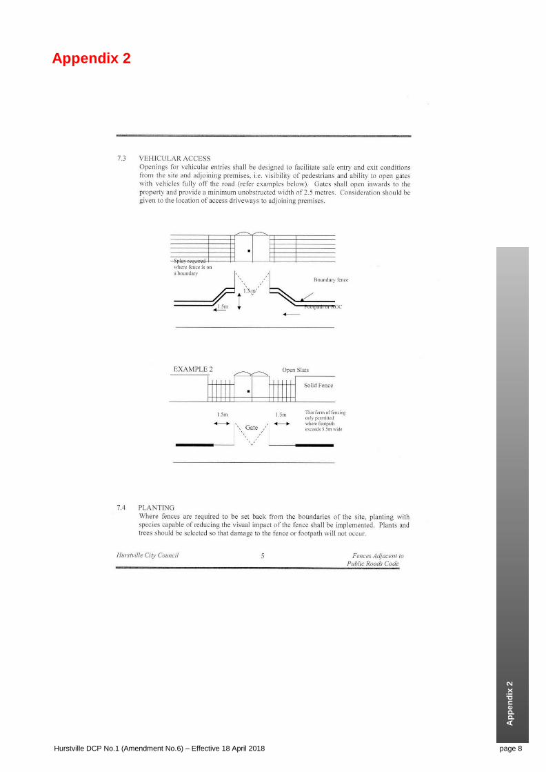
2 Fencing Adjacent to Public Roads
Purpose
This code outlines Council’s policy in respect of the erection of street boundary fences in excess of one (1) metre in height.
Aims of Code
To provide guidelines for the erection of fences and walls in excess of one (1) metre in height above footpath level.
To ensure that:
Fences complement and are compatible with the development of the land.
Adverse impact of fences on the streetscape and public places is minimised.
Fences do not adversely affect the character or amenity of the locality by their visual impact, size,
overshadowing or other factors.
To ensure that safe vehicular access is maintained at property entrances and street intersections.
To maximise recreational space, privacy and security of residential dwellings adjoining roads, and places of public congregation, (eg bus stops) and for residential developments, townhouses, villas and dual occupancy.
To encourage the use of a diverse range of fencing designs and materials.
Consideration of Applications
In any application for the erection of courtyard walls and/or fences the Council may consider the following:
The purpose for which the fence or wall is required.
The position of the fence or wall in relation to the boundaries of the allotment and building
alignments.
Height, materials and design of the proposed fence.
The general scale and appearance of the fence or wall relative to the general streetscape and
amenity of the neighbourhood and the existence of similar structures in the neighbourhood.
Structural stability of the proposed work.
The possible effects of the structure on the safety of pedestrians and traffic conditions in the
adjoining road system.
The landscaping, both existing and proposed, and its effect on the embellishment of the proposed
structure.
The effects of the proposed structure on drainage.
Current open space and open space utilisation on site.
Levels of traffic on adjoining roads.
Approvals and Requirements
Applications/ Obtaining Approval
To see if you need approval/what sort of approval you require refer to State Environmental Planning Policy (Exempt and Complying Codes) 2008. Some minor projects do not require approval under certain circumstances, some require a complying development certificate and others a development consent and construction certificate.
Required Information
Applications must be completed and signed by the owner, builder, architect or engineer and accompanied by documents as show on the relevant application form. Fees apply as listed in our Schedule of Fees and Charges which may be down loaded from our website.
Applications for enclosure of the site shall be accompanied by a statement setting out the reasons for the proposed wall.

Ap
pe
nd
ix 2
Appendix 2
Hurstville DCP No.1 (Amendment No.6) – Effective 18 April 2018 page 7
Plans
Site Plan
The site plan shall be drawn at a scale of 1:200 or 1:500 and include:
a. Boundaries and dimensions of the site including location of the proposed fence, with gate openings, offsets,
splay corners and returns relative to boundaries and existing structures on the site.
b. Location and dimensions of any easements.
c. North point.
d. Location of vehicular crossings including obstructions such as power poles and gully pits.
e. Location of existing vegetation including trees having a girth in excess of 300mm.
f. Proposed landscaping including species and projected height at maturity.
A layout of proposed drainage lines, where necessary.
Foreshore Building Line, if applicable.
General Plan
The general plan shall be drawn at a scale of 1:100 or 1:50 and include:
a. Elevations and plan view
b. Height, design, colours and construction of the fence
c. A sectional elevation of the wall including footings indicating adjoining ground levels and location of
adjoining property boundaries, where relevant
Specification
Specifications shall describe construction and materials of the fence, whether materials will be new or second-hand and include details of any proposed surface stormwater drainage or agricultural drainage.
General Requirements
Dividing Fences Act
The provisions of the Dividing Fences Act, 1991, must be considered with the design of fences. This Act is not administered by Council. The provisions of this Act regulate the construction and repair of dividing fences between properties including procedures for the apportionment of costs between owners.
Fence Design
Fences shall be designed so as to be compatible with the adjoining buildings and fences and the natural surroundings.
The design should demonstrate architectural merit and relief from a mass of wall is encouraged by the use of vertical columns, brick capping, variable brickwork bonds, timber panel inserts and open metal or timber panels. Fences on premises with heritage classifications should be in harmony with existing building/s.
Ap
pe
nd
ix 2
Appendix 2
Hurstville DCP No.1 (Amendment No.6) – Effective 18 April 2018 page 8

Ap
pe
nd
ix 2
Appendix 2
Hurstville DCP No.1 (Amendment No.6) – Effective 18 April 2018 page 9

Ap
pe
nd
ix 2
Appendix 2
Hurstville DCP No.1 (Amendment No.6) – Effective 18 April 2018 page 10

Ap
pe
nd
ix 2
Appendix 2
Hurstville DCP No.1 (Amendment No.6) – Effective 18 April 2018 page 11

Ap
pe
nd
ix 2
Appendix 2
Hurstville DCP No.1 (Amendment No.6) – Effective 18 April 2018 page 12

Ap
pe
nd
ix 2
Appendix 2
Hurstville DCP No.1 (Amendment No.6) – Effective 18 April 2018 page 13
3 Balcony Enclosures in Residential Flat Buildings Policy
Note: The Balcony Enclosures Residential Flat Buildings Policy was originally adopted by Council on 28 February 2001
1. The full enclosure of balconies required by Council’s Code to provide private open space for dwelling units in residential flat buildings be discouraged unless all of the following criteria can be satisfied:
The dwelling unit has an alternative (ie, second balcony) which satisfies the open space
requirements of Council’s Codes.
The enclosure does not cause the gross floor plan area to exceed the permissible floor space index
for the allotment on which the building stands.
The external appearance of the building is not degraded when visible from a public place.
The building is recessed within the line of the external walls or is framed by solid walling, piers or
columns and is under the main roof line of the building.
The deemed to satisfy requirements of the Building Code of Australia are satisfied relating to
vertical fire separation between storeys and with respect to fire exposure to boundary or other
building fire source features, and the requirements for the safe cleaning of windows within
acceptable reach from within the building.
The outdoor amenity of a balcony due to its exposure to the elements or to a significant noise
source is so adverse for the majority of time and seasons that it is rendered totally unusable for
recreational purposes.
The actual exposure to elements such as wind, rain, noise be documented by an appropriately
qualified person in a Statement of Environmental Effects.
The enclosure is subject to no blinds or curtains being installed behind glass to provide sun
shading or tinting to reduce heat build-up on the balconies and the Owners Corporation of the
Strata Plan be required to endorse and enforce this requirement through its By-Laws.
Glare and rogue reflections to traffic (pedestrian or road traffic) can be shown not to be significant
for enclosures involving more than 50% glass area compared to the area of the respective
elevation of the balcony.
The building alterations are designed by a qualified architect in accordance with urban design
guidelines.
2. The enclosure of balconies which project outside the main external wall line be not approved.
3. The enclosure of balconies with full storey height glazing be not approved.
4. The piece-meal enclosure of balconies be not approved, but the balcony enclosures may only apply to one side/section of a building.
5. For balcony enclosures which satisfy the criteria in (1) above an overall scheme shall be implemented with the Concurrence of the Owners Corporation of the Strata Plan using the same materials or materials which will harmonise with the materials existing in the building façade.
6. Partial enclosure of balconies be allowed on the same terms and conditions as specified in 5 above.
7. The enclosure of balconies on landmark buildings be denied, i.e. those buildings which are both clearly visible when seen on a viewing axis towards Hurstville and clearly distinguishable from other buildings (eg. 323 Forest Road (Meriton), 109 Forest Road (Forest View)) but not those which are simply visible when a fair distance from Hurstville (eg. 2 original Meriton towers).
Ap
pe
nd
ix 2
Appendix 2
Hurstville DCP No.1 (Amendment No.6) – Effective 18 April 2018 page 14
4 Public Spaces Local Approvals Policy
Please refer to Council’s Public Spaces Local Approvals Policy on Council’s website
http://www.hurstville.nsw.gov.au/Public-Spaces-Local-Approvals-Policy.html

Ap
pe
nd
ix 2
Appendix 2
Hurstville DCP No.1 (Amendment No.6) – Effective 18 April 2018 page 15
5 Satellite Dish Policy
Objective:
To minimise the visual impact of satellite dishes in residential areas that may adversely affect the visual amenity of neighbours and the public domain.
Guidelines:
General
This policy is applicable to all residential dwellings. The following guidelines need to be considered when assessing an application to erect a satellite dish:-
Satellite dishes are;
Not to be located on the front façade of buildings, or in front setback areas visible from the street.
Located so as not to cast glare or interfere with neighbours views.
To be consistent with the surrounding residential environment in terms of height, scale, colour and location.
To be complementary to the design and character of the existing residential building.
Restricted to one per building regardless of the number of units.
Not to be located on balconies or carports.
A roof mounted satellite dish shall;
Be located below the ridgeline of the roof (on a pitched roof).
Not be placed on the dwelling if the diameter is in excess of 1.5 metres.
Be of a colour consistent with the roofing material.
Not to be installed on a flat roof (unless on a residential flat building).
Not front the street.
A ground mounted satellite dish shall;
Not exceed a maximum height of 1.8 metres.
Be setback from the side and rear boundary by at least three (3) metres. All parts must be within
property boundaries and must not encroach onto any adjoining property or over any public space
including a road.
Be adequately screened (for eg; by vegetation).

Ap
pe
nd
ix 2
Appendix 2
Hurstville DCP No.1 (Amendment No.6) – Effective 18 April 2018 page 16
6 Code for the Erection of Private Tennis Courts
Purpose
This Code has been established to outline Council’s policy in respect of private tennis courts on residential land.
Each application will be considered on its merits, having regard to the aims and guidelines detailed in this Code.
Aims of Code
a. To provide guidelines for the erection of private tennis courts on residential land.
b. To permit the reasonable enjoyment of land by recognising the rights of individuals to develop their land.
c. To ensure that private tennis courts do not adversely affect the amenity of the locality by their visual impact.
d. To control the use of private tennis courts so there is no adverse impact on the neighbourhood due to loss of
privacy, excessive noise or spill or artificial light.
e. To maintain, where possible, existing trees that are subject to Clause 4.9 Management of Trees and
Vegetation, of the Hurstville LEP 2012.
Approvals and Requirements
A development consent and a construction certificate must be obtained for all private tennis courts on residential land.
Required Information
Application for approval must include 6 copies of plans and specifications and the following information:
a. Details of proposed hours of operation
b. Details of proposed artificial lighting including any shields
c. Details of proposed court surface
d. Details of proposed perimeter landscaping, acoustic screens or similar
e. Details of site filling or excavation works, including retaining walls
Plans
Site Plan
The site plan must include:
a. Location and dimensions of the site including location of the proposed tennis court relative to boundaries
and existing structures on site.
b. Location of structures on adjoining properties.
c. Location and dimensions of any easements.
d. North point.
e. Location, size and type of existing vegetation on site including any species to be removed.
f. Existing drainage lines and proposed stormwater drainage system for the tennis court.
g. Location of any proposed lighting.
General Plan
The general plan shall show the elevation from adjoining properties, including details of height and construction materials of proposed fencing and details of artificial lighting, including any shields.
Design and Siting of Private Tennis Courts

Ap
pe
nd
ix 2
Appendix 2
Hurstville DCP No.1 (Amendment No.6) – Effective 18 April 2018 page 17
Location
Private tennis courts must comply with the following setbacks:
a. The tennis courts must be sited to provide a minimum separation of 1.5m from site boundaries and 6 metres
from adjoining dwellings.
b. The tennis court must comply with the Building Line adopted by Council. Details may be obtained from
Council.
c. Tennis courts are not permitted between Mean High Water Mark and the Foreshore Building Line.
d. Tennis courts must be located to maintain existing substantial trees and shrubs where possible.
Design
To minimise impact on adjoining premises the following guidelines must be used in the design of private tennis courts.
a. Fencing shall not be solid – black or green PVC costed wire fencing is preferred.
b. Extensive planting must be provided between the tennis court and site boundaries to provide a dense
screen.
c. Site excavation and filling must be kept to a minimum. Retaining walls may be required where cut or fill
exceeds 600mm.
d. Tennis courts in Foreshore Scenic Protection Areas must be designed to be unobtrusive and complement
the surrounding area, maintain water views and to minimise the visual appearance from waterways.
e. Artificial lighting will not be considered unless lighting is shielded to prevent the spill of light onto adjoining
properties. Technical details of the lighting shall be submitted by a lighting consultant expert in that field of
design. Glare from lighting to adjoining neighbours is to be eliminated.
Drainage
Surface water must be connected by way of 100mm PVC pipeline to:
a. The street gutter; or
b. An existing common drainage line; or
c. Council stormwater drainage line subject to the approval.
d. Water storage tanks with drip feed water irrigation system. Overflows of water storage tanks are to be
directed to the street gutter where possible; or
e. To a minimum 3000mm long x 600mm deep absorption trench, located at right angles to the fall of the land
and a minimum of 3m from boundaries and other building boundaries. This method will only be permitted
where it is not possible to use any of the above methods and conditions favour on-site disposal.
f. A kerb or dish drain must be provided to the lower side of the tennis court to collect and channel stormwater
to a 450mm x 450mm by 600mm deep gully pit.
Hours of Operation
Use of tennis courts will be limited to between the hours of 7.00am and 10.00pm, except where varied by conditions of approval.

Ap
pe
nd
ix 2
Appendix 2
Hurstville DCP No.1 (Amendment No.6) – Effective 18 April 2018 page 18
7 Stencilling of Street Driveways Policy
Adopted by Council
20 March 2002
(1) THAT Council affirms the policy that all driveways in Hurstville are finished in plain concrete, and
(2) FURTHER, THAT in streets which have brick paved surfaces, driveways are constructed to Council’s Engineering Specification including a concrete base with matching brick paving surface.

Ap
pe
nd
ix 2
Appendix 2
Hurstville DCP No.1 (Amendment No.6) – Effective 18 April 2018 page 19
8 Underground Electricity Cabling to Developments Policy
Adopted by Council
6th
July, 1978
(3) THAT in all future roaded subdivisions, electricity supply be undergrounded.
Minute Number 626
Adopted by Council
12 November 1997
1. For all developments in the Hurstville CBD;
Developer to pay full costs of undergrounding low voltage cables adjacent to the development.
Developer to provide conduits only for future undergrounding of high voltage cables.
2. For all commercial/industrial and medium high density residential developments elsewhere in the City;
Developer to provide conduit for future undergrounding of low voltage cables only.
Developer to provide connection to future underground supply to development.

Ap
pe
nd
ix 2
Appendix 2
Hurstville DCP No.1 (Amendment No.6) – Effective 18 April 2018 page 20
9 Design Guidelines for Absorption Trenches
These guidelines apply to the following Residential Development types:
Dwelling Houses (on standard and small lots) including alterations and additions,
Secondary Dwellings and,
Dual Occupancy development.
Definition of ‘Drainage of low level properties’ - A portion of a low level property that slopes away from the street
can be drained to an absorption/an infiltration trench.
System feasibility
Infiltration systems are generally not suitable for sites with the following limitations:
Heavy clays.
Exposed bedrock or shallow soils over rock or shale.
Steep terrain (> 15%).
High water table (the base of the infiltration system should be higher than the water table).
Potentially salinity hazard areas.
Contaminated land.
Storage
Void type absorption trenches are preferred.
These are devices which provide storage space as a void inside the device structure such as leaky pipes, absorption
pits and absorption tanks.
Design guidelines
a) For sites with impervious areas < 50% of the site area, absorption systems shall be designed to the 20 year ARI
design storm.
b) A design and supporting calculations for the proposed absorption system, prepared by a suitably qualified and
experienced engineer, shall be supplied by the applicant in conjunction with the development application. The
design shall be accompanied by a report prepared by a geotechnical engineer including all necessary
geotechnical information required to support the design and the assessment of the soil’s hydraulic conductivity.
c) Hydraulic conductivity (percolation) for the soil should be measured by a qualified geotechnical engineer. At least
one test hole per site (at the location of the proposed absorption system) is to be dug to a minimum depth of 1.00
m below the surface. The percolation test is to be undertaken using a recognised falling head or constant head
test.
d) Where high water table is encountered, the base of the absorption system should be at least 0.5 m above the
water table to accommodate fluctuations of the ground water. Where rock is encountered, the trench base should
be at least 0.5 m above the rock to provide sufficient drainage area. Alternative design should be considered
where there is difficulty in achieving either of these requirements.
e) The on-site absorption system should not be located within 1.5 m of the side or rear property, nor 3 m from any
on-site building or neighbouring buildings. Where the absorption system is less than 3 m from any building, the
building should be supported on a pier and beam foundation as detailed and certified by the structural engineer.
A site plan showing the location of absorption system/s relative to fences and to the buildings on the site and on
neighbouring properties is to be provided.
f) The absorption system should not be placed under any paved surfaces and must be at least 1.0 metres from
pavements subject to vehicular traffic.
g) A debris/silt collection pit shall be constructed immediately upstream of the underground system, a capped
observation riser installed over the underground system and the area downstream is to be landscaped in a
manner that will ensure a reduction of sub-soil flows into the adjoining property.

Ap
pe
nd
ix 2
Appendix 2
Hurstville DCP No.1 (Amendment No.6) – Effective 18 April 2018 page 21
Sizing methodology
a) From the intensity duration values for storms ranging in duration from 5 minutes to 72 hours, runoff volume is
calculated by the formula:
QT = C x IT x d x Ac
where
QT = total runoff volume (m3)
C = Runoff coefficient (dimensionless)
IT = average rainfall intensity for a given ARI storm (mm/hr)
d = storm duration (minute)
Ac= catchment area (m2)
b) The amount of infiltration during the storm event is calculated by the formula:
Qinf = f/s x Asurf
where,
Qinf = stormwater infiltrated during the storm event (m3)
s = factor of safety for soil infiltration rate (use a value of 5 for average application)
f = hydraulic conductivity of the soil (m/sec)
Asurf = infiltration surface.
c) The difference in the above quantities is calculated:
Vs = QT - Qinf
where
Vs = volume of water to be infiltrated (m3)
d) For trench-type system, the porosity of the stone filled storage is also taken into account and the minimum trench
dimensions are calculated by the formula:
Vtr = Vs / n
Where
Vtr = trench volume required (m3)
n = void ratio of the stone filled trench (see the following table)
Material Voids (n)
Clean stone 0.4 - 0.5
Uniform gravel 0.3 - 0.4
Graded sand or gravel 0.2 - 0.3
This procedure is carried out for each average rainfall intensity for each storm duration; the required size of the
trench is the largest calculated.
e) Finally, the time of emptying of the absorption system should be checked not to exceed 72 hours.