app fotovoltaici 2010 gb:contatori - mit · app fotovoltaici 2010 gb:contatori 08/10/10 12:56...
TRANSCRIPT

app fotovoltaici 2010 GB:Contatori 08/10/10 12:56 Pagina 1

srl was established in Milan, in 1983, with the intention of design andproduction of electrical measurement and control equipment for the electric andautomation industries, accommodating all standard electrical parameters.
In doing took full advantage of latest technologies to produce modernhigh quality products taking into consideration the requirements of each potentialindustry in relation to their installation and use in the field.It has always been Revalcos’ strategy to see that global quality is maintained to thehigh standard incorporated in the manufacture as managed by definite qualityprocedures supported by the Quality Assurance Officers. The procedures that thathave been adopted and the organisation to apply them, has been approved by theCSQ (Certification of Quality Systems) and has certified that the quality of thesystems conform to the standards of UNI EN ISO 9001/2000.The CISQ Federation (Italian Certification of Quality Systems), of which CSQ is anintegral branch has collaborated with the certification offices of IQNet (InternationalQuality Systems Assessment and Certification Network), to gain a mutualagreement in the recognition of the certifications.As a result of this agreement can claim the IQNet certification andinternational validity of CSQ certification. This prestigious recognition confirmsthe quality standard of products.
The range of products cover a full market range of Analogue and Digitalinstruments, ranging from standard Ammeters and Voltmeters through tosophisticated Electronic Analysers and Multifunction Metering Systems, forboth flush Panel, Switchboard mounting and also for Din Rail mounting.These are supported by a wide range of associated equipment such asCurrent and Voltage Transformers and Shunts, Measurement Transducers,Control Relay and Surge Protection.Other products available includes Time and Pulse Counters, Switches,Audio Alarms and Buzzers, Timers, Power Supplies, and Earth Leakagemeasurement equipment. Safety Transformers for general use and BellTransformers Din Rail Modular versions being the latest additions tothe very comprehensive range of products available from .
Visit our Web Site www.revalco.it for further details.
®
app fotovoltaici 2010 GB:Contatori 08/10/10 12:56 Pagina 2

3
ANALOGUE INSTRUMENTSVOLTMETERS, MOVING COIL INSTRUMENTS FOR DIRECT CURRENT . . . . . . . . . . . . . . . . . . . . . . . . . . . . . . . . . . . . . . . 4AMMETERS, MOVING COIL INSTRUMENTS FOR DIRECT CURRENT . . . . . . . . . . . . . . . . . . . . . . . . . . . . . . . . . . . . . . . . . 5
HOUR METERS . . . . . . . . . . . . . . . . . . . . . . . . . . . . . . . . . . . . . . . . . . . . . . . . . . . . . . . . . . . . . . . . . . . . . . . . . . . . . . . . . . . . . .6
HOUR METERS
VOLTMETERS 800V DC + option RS485 + option 4/20mA . . . . . . . . . . . . . . . . . . . . . . . . . . . . . . . . . . . . . . . . . . . . . . . . . . 8AMMETERS 5A (1A) or 60mV with “I max demand” + option RS485 + option 4/20mA . . . . . . . . . . . . . . . . . . . . . . . . . . . 9PROGRAMMINGS . . . . . . . . . . . . . . . . . . . . . . . . . . . . . . . . . . . . . . . . . . . . . . . . . . . . . . . . . . . . . . . . . . . . . . . . . . . . . . . . . . 10
DIGITAL INSTRUMENTS
LCD - 4 DIN MODULES D.C. VERSION . . . . . . . . . . . . . . . . . . . . . . . . . . . . . . . . . . . . . . . . . . . . . . . . . . . . . . . . . . . . . . . . 12
MULTIFUNCTION METERS
FOR DIRECT CURRENT . . . . . . . . . . . . . . . . . . . . . . . . . . . . . . . . . . . . . . . . . . . . . . . . . . . . . . . . . . . . . . . . . . . . . . . . . . . . . 17
kWh-METERS
SINGLE PHASE . . . . . . . . . . . . . . . . . . . . . . . . . . . . . . . . . . . . . . . . . . . . . . . . . . . . . . . . . . . . . . . . . . . . . . . . . . . . . . . . . . . . 18
MEASUREMENT TRANSDUCERS - TRUE RMS
CURRENT - EXTERNAL POWER SUPPLY 1CORIC . . . . . . . . . . . . . . . . . . . . . . . . . . . . . . . . . . . . . . . . . . . . . . . . . . . . . . . 19VOLTAGE - EXTERNAL POWER SUPPLY 1CORUC . . . . . . . . . . . . . . . . . . . . . . . . . . . . . . . . . . . . . . . . . . . . . . . . . . . . . . . 191 DIN MODULE . . . . . . . . . . . . . . . . . . . . . . . . . . . . . . . . . . . . . . . . . . . . . . . . . . . . . . . . . . . . . . . . . . . . . . . . . . . . . . . . . . . . 20
MEASUREMENT TRANSDUCERS
VARISTOR SYSTEM . . . . . . . . . . . . . . . . . . . . . . . . . . . . . . . . . . . . . . . . . . . . . . . . . . . . . . . . . . . . . . . . . . . . . . . . . . . . . . . . 20WITH CURRENT LIMITER - C GROUP . . . . . . . . . . . . . . . . . . . . . . . . . . . . . . . . . . . . . . . . . . . . . . . . . . . . . . . . . . . . . . . . . . 21
SURGE ARRESTERS
ONE OUTPUT RELAY . . . . . . . . . . . . . . . . . . . . . . . . . . . . . . . . . . . . . . . . . . . . . . . . . . . . . . . . . . . . . . . . . . . . . . . . . . . . . . . 17
TWO OUTPUT RELAYS . . . . . . . . . . . . . . . . . . . . . . . . . . . . . . . . . . . . . . . . . . . . . . . . . . . . . . . . . . . . . . . . . . . . . . . . . . . . . . 17
MULTIVOLTAGE RELAYS
“HALL” EFFECT . . . . . . . . . . . . . . . . . . . . . . . . . . . . . . . . . . . . . . . . . . . . . . . . . . . . . . . . . . . . . . . . . . . . . . . . . . . . . . . . . . . 23
CURRENT TRANSFORMERS
SHUNTS . . . . . . . . . . . . . . . . . . . . . . . . . . . . . . . . . . . . . . . . . . . . . . . . . . . . . . . . . . . . . . . . . . . . . . . . . . . . . . . . . . . . . . . . . . 25
SHUNTS
1RCD1485 . . . . . . . . . . . . . . . . . . . . . . . . . . . . . . . . . . . . . . . . . . . . . . . . . . . . . . . . . . . . . . . . . . . . . . . . . . . . . . . . . . . . . . . . . 20
RS485 CONCENTRATOR
app fotovoltaici 2010 GB:Contatori 08/10/10 12:56 Pagina 3
4
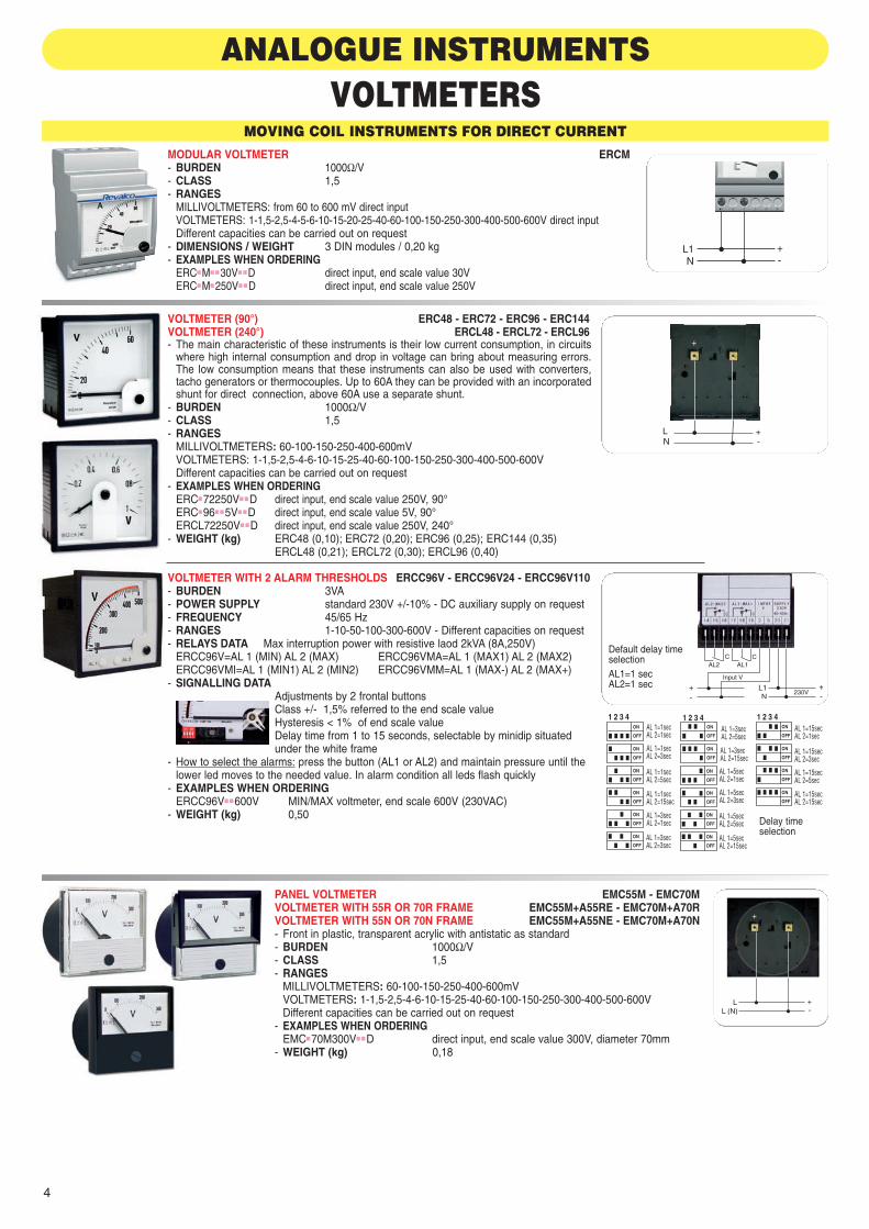
ANALOGUE INSTRUMENTSVOLTMETERS
PANEL VOLTMETER EMC55M - EMC70MVOLTMETER WITH 55R OR 70R FRAME EMC55M+A55RE - EMC70M+A70RVOLTMETER WITH 55N OR 70N FRAME EMC55M+A55NE - EMC70M+A70N- Front in plastic, transparent acrylic with antistatic as standard- BURDEN 1000Ω/V- CLASS 1,5- RANGES
MILLIVOLTMETERS: 60-100-150-250-400-600mVVOLTMETERS: 1-1,5-2,5-4-6-10-15-25-40-60-100-150-250-300-400-500-600VDifferent capacities can be carried out on request
- EXAMPLES WHEN ORDERINGEMC■70M300V■ ■D direct input, end scale value 300V, diameter 70mm
- WEIGHT (kg) 0,18
MOVING COIL INSTRUMENTS FOR DIRECT CURRENT
VOLTMETER (90°) ERC48 - ERC72 - ERC96 - ERC144VOLTMETER (240°) ERCL48 - ERCL72 - ERCL96 - The main characteristic of these instruments is their low current consumption, in circuits
where high internal consumption and drop in voltage can bring about measuring errors.The low consumption means that these instruments can also be used with converters,tacho generators or thermocouples. Up to 60A they can be provided with an incorporatedshunt for direct connection, above 60A use a separate shunt.
- BURDEN 1000Ω/V- CLASS 1,5- RANGES
MILLIVOLTMETERS: 60-100-150-250-400-600mVVOLTMETERS: 1-1,5-2,5-4-6-10-15-25-40-60-100-150-250-300-400-500-600VDifferent capacities can be carried out on request
- EXAMPLES WHEN ORDERINGERC■72250V■ ■D direct input, end scale value 250V, 90°ERC■96■ ■5V■ ■D direct input, end scale value 5V, 90°ERCL72250V■ ■D direct input, end scale value 250V, 240°
- WEIGHT (kg) ERC48 (0,10); ERC72 (0,20); ERC96 (0,25); ERC144 (0,35) ERCL48 (0,21); ERCL72 (0,30); ERCL96 (0,40)
MODULAR VOLTMETER ERCM- BURDEN 1000Ω/V- CLASS 1,5- RANGES
MILLIVOLTMETERS: from 60 to 600 mV direct inputVOLTMETERS: 1-1,5-2,5-4-5-6-10-15-20-25-40-60-100-150-250-300-400-500-600V direct inputDifferent capacities can be carried out on request
- DIMENSIONS / WEIGHT 3 DIN modules / 0,20 kg- EXAMPLES WHEN ORDERING
ERC■M■ ■30V■ ■D direct input, end scale value 30VERC■M■250V■ ■D direct input, end scale value 250V
L1N
+-
VOLTMETER WITH 2 ALARM THRESHOLDS ERCC96V - ERCC96V24 - ERCC96V110- BURDEN 3VA- POWER SUPPLY standard 230V +/-10% - DC auxiliary supply on request - FREQUENCY 45/65 Hz - RANGES 1-10-50-100-300-600V - Different capacities on request- RELAYS DATA Max interruption power with resistive laod 2kVA (8A,250V)
ERCC96V=AL 1 (MIN) AL 2 (MAX) ERCC96VMA=AL 1 (MAX1) AL 2 (MAX2)ERCC96VMI=AL 1 (MIN1) AL 2 (MIN2) ERCC96VMM=AL 1 (MAX-) AL 2 (MAX+)
- SIGNALLING DATAAdjustments by 2 frontal buttonsClass +/- 1,5% referred to the end scale valueHysteresis < 1% of end scale valueDelay time from 1 to 15 seconds, selectable by minidip situated under the white frame
- How to select the alarms: press the button (AL1 or AL2) and maintain pressure until thelower led moves to the needed value. In alarm condition all leds flash quickly
- EXAMPLES WHEN ORDERINGERCC96V■ ■600V MIN/MAX voltmeter, end scale 600V (230VAC)
- WEIGHT (kg) 0,50
AL 1=1secAL 2=1sec
AL 1=1secAL 2=3sec
AL 1=1secAL 2=5sec
AL 1=1secAL 2=15sec
AL 1=3secAL 2=1sec
AL 1=3secAL 2=3sec
AL 1=3secAL 2=5sec
AL 1=3secAL 2=15sec
AL 1=5secAL 2=1sec
AL 1=5secAL 2=3sec
AL 1=5secAL 2=5sec
AL 1=5secAL 2=15sec
AL 1=15secAL 2=1sec
AL 1=15secAL 2=3sec
AL 1=15secAL 2=5sec
AL 1=15secAL 2=15sec
230V
C
Input V
CAL2 AL1
Delay timeselection
Default delay timeselectionAL1=1 secAL2=1 sec
app fotovoltaici 2010 GB:Contatori 08/10/10 12:56 Pagina 4

5
AMMETERS
VOLTMETER (HORIZONTAL PROFILE VERSION) ERPC24/OVOLTMETER (VERTICAL PROFILE VERSION) ERPC24/V- BURDEN 1mA- CLASS 1,5- RANGES:
MILLIVOLTMETERS: 60÷300mVVOLTMETERS: 1-1,5-2,5-4-6-10-15-30-40-50-60-80-100-150-200-250-300-400-500-600VDifferent capacities can be carried out on request
- EXAMPLES WHEN ORDERINGERPC24/V■100V■D direct input, end scale value 100V (vertical)ERPC24/O■ ■10V■D direct input, end scale value 10V (horizontal)
+-
MOVING COIL INSTRUMENTS FOR DIRECT CURRENTMODULAR AMMETER ERCM- BURDEN 60mV- CLASS 1,5- RANGES
MICROAMMETERS: 100-150-250-400-500-600µA direct inputMILLIAMMETERSI: from 1 to 600 mA 4/20mA direct inputAMPEROMETRI: 1-1,5-2,5-4-5-6-10-15-20-25-30A direct input
.../60mV input by shunt, secondary 60mVDifferent capacities can be carried out on request
- DIMENSIONS / WEIGHT 3 DIN modules / 0,20 kg- EXAMPLES WHEN ORDERING
ERC■M■ ■60MV■ ■S input by shunt, secondary 60mV, without scale plateESC■M■200A■ ■60MV scale plate for ERCM, 200A/60mVERC■M■ ■ ■5A■ ■D direct input, end scale value 5A
Shunt inputDirect input
L1N
+-
+-
AMMETER INTERCHANGEABLE SCALE PLATE (90°) ERC48 - ERC72 - ERC96 - ERC144AMMETER INTERCHANGEABLE SCALE PLATE (240°) ERCL48 - ERCL72 - ERCL96- The main characteristic of these instruments is their low current consumption, in circuits where high internal con-
sumption and drop in voltage can bring about measuring errors. The low consumption means that these instru-ments can also be used with converters, tacho generators or thermocouples. Up to 60A they can be providedwith an incorporated shunt for direct connection, above 60A use a separate shunt.
- BURDEN 60mV- CLASS 1,5- RANGES
MICROAMMETERS (ERC) 50-60-80-100-150-250-400-600-800-900µAMICROAMMETERS (ERCL) 100-150-250-400-600-800-900µAMILLIAMMETERS: 1-1,5-2,5-4-5-6-10-15-20-25-40-60-100-150-250-400-600-800-900mA
4/20mAAMMETERS: 1-1,5-2,5-4-6-10-15-25-40-60A direct input
.../60mV, .../150mV input by shunt, secondary 60mV or 150mVDifferent capacities can be carried out on request
- EXAMPLES WHEN ORDERINGERC■96■60A■D direct input, end scale value 60A, 90° ERC■96■60MV■ ■S input by shunt, secondary 60mV, without scale plateESC96300A600MV scale plate for ERC96, 300A/60mV
- WEIGHT (kg) ERC48 (0,10); ERC72 (0,20); ERC96 (0,25); ERC144 (0,35) ERCL48 (0,21); ERCL72 (0,30); ERCL96 (0,40)
Direct input
Shunt input
AMMETER WITH 2 ALARM THRESHOLDS ERCC96A - ERCC96A24 - ERCC96A110- BURDEN 3VA- POWER SUPPLY standard 230V +/-10%
DC auxiliary supply on request - FREQUENCY 45/65 Hz - RANGES
MILLIAMMETERS: 1-20-4/20 mA (other on request)AMMETERS: 60mV, input by shunt (other on request)
- RELAYS DATA Max interruption power with resistivelaod 2kVA (8A,250V)
ERCC96A=AL 1 (MIN) AL 2 (MAX) ERCC96AMA=AL 1 (MAX1) AL 2 (MAX2)ERCC96AMI=AL 1 (MIN1) AL 2 (MIN2) ERCC96AMM=AL 1 (MAX-) AL 2 (MAX+)
- SIGNALLING DATAAdjustments by 2 frontal buttonsClass +/- 1,5% referred to the end scale valueHysteresis < 1% of end scale valueDelay time from 1 to 15 seconds, selectable by minidip situated under the white frame
- How to select the alarms: press the button (AL1 or AL2) and maintain pressure until thelower led moves to the needed value. In alarm condition all leds flash quickly
- EXAMPLES WHEN ORDERINGERCC96A■ ■100A1 MIN/MAX ammeter, end scale 100/60mV (230VAC)
- WEIGHT (kg) 0,50
AL 1=1secAL 2=1sec
AL 1=1secAL 2=3sec
AL 1=1secAL 2=5sec
AL 1=1secAL 2=15sec
AL 1=3secAL 2=1sec
AL 1=3secAL 2=3sec
AL 1=3secAL 2=5sec
AL 1=3secAL 2=15sec
AL 1=5secAL 2=1sec
AL 1=5secAL 2=3sec
AL 1=5secAL 2=5sec
AL 1=5secAL 2=15sec
AL 1=15secAL 2=1sec
AL 1=15secAL 2=3sec
AL 1=15secAL 2=5sec
AL 1=15secAL 2=15sec
Input A
230V
CCAL2 AL1
Delay timeselection
Default delay timeselectionAL1=1 secAL2=1 sec
app fotovoltaici 2010 GB:Contatori 08/10/10 12:56 Pagina 5

6
Direct input
Shunt input
PANEL AMMETER EMC55M - EMC70MAMMETER WITH 55R OR 70R FRAME EMC55M+A55RE - EMC70M+A70RAMMETER WITH 55N OR 70N FRAME EMC55M+A55NE - EMC70M+A70N- Housing in thermoplastic resin. Front in plastic, transparent acrylic with antistatic as standard- BURDEN 60mV- CLASS 1,5- RANGES
MICROAMMETERS: 50-60-100-150-250-400-500-600-800-900µA direct inputMILLIAMMETERS: 1-1,5-2,5-4-5-6-10-15-20-25-30-40-60-100-150-250-400-600-800-900mA
4/20mAAMMETERS: 1-1,5-2,5-4-5-6-10-15-20-25-30-40-50-60A direct input
.../60mV input with Shunt, secondary 60 mVDifferent capacities can be carried out on request
- EXAMPLES WHEN ORDERINGEMC■70M■60A■ ■D direct input, end scale value 60A, 1In (60A), Ø70 mm
- WEIGHT (kg) 0,18
AMMETER (HORIZONTAL PROFILE VERSION) ERPC24/OAMMETER (VERTICAL PROFILE VERSION) ERPC24/V- BURDEN 1mA- CLASS 1,5- RANGES:
MICROAMMETERS: 25-50-100-150-200-250-500 µAMILLIAMMETERS: 1-5-10-50-100-150-200-250-500-600mA
4/20mAAMMETERS: 1-1,5-2-2,5-3-4-5A direct input
.../60mV input with Shunt, secondary 60 mVDifferent capacities can be carried out on request
- EXAMPLES WHEN ORDERINGERPC24/0■4-20MA direct input, end scale value 4/20mA
Direct input
Shunt input
- The hour meters are instruments for measuring time which are particulary suitable for:- determing the functioning time of electrical machines, elevators, boilers, electrical stoves etc.- determing the intervention time for changing the oil, replacing ball bearings etc. on machinery that is in constant use.- determing the functioning time of new machinery with the purpose of establishing when the guarantee expires, such as current rectifiers,
valves, lamps etc.- determing the sum of the periods during fatigue tests, the duration of electrochemical processes etc.
- In the DC version the movement of the motor is adjusted by a quartz crystal with great stability and a frequency such that, at every 22 degrees of oscillation,an impulse is released when amplified, activates electromagnetic converter. The display is composed by 6 entires and 1 decimal (4 mm height)
- At the end of the counter, the counting begin again automatically from zero. It is not possible to reset the device.- The necessary voltage is 1,2....1,6V.- The precision is obtained by means of a variable condenser with a tolerance of +/-0,2 sec/day at room temperature.- Operating temperature: between -10°C and +55°C. Mounting position is indifferent and the housing is in black plastic material.- The reading class is 1/100 h (36 sec). This hourmeters are manufactured following the UL, IEC, TGL21-366, DIN Standards
4RH724RH96
ADAPTER FRAMES
AMRK5555AMRK7272 AMRKO58
AMRKO72
AMRK4848
AMRK2448
for 4RK30 for 4RK46
AM72
4RK30Fast-on 6,3x0,8 mmwith screws terminal
4RK46
- Dimensions in mm
HOUR METERS
app fotovoltaici 2010 GB:Contatori 08/10/10 12:56 Pagina 6

7
4RK7R
SWITHCBOARD VERSION
DC AC AND DCCURRENT CURRENT
4RH 4RK30 4RK47R - 4RK46Q- BURDEN from 0,07 to 2W from 0,04 to 0,2W- POWER SUPPLY (to specify) 10...50 V 12...36V 10...60V / 80...150V /
150...250V (+10% / -15%)- DISPLAY 999999,9 h (6 entires + 1 decimal) 99999,99 h (5 ent. + 2 dec.)- PROTECTION DEGREE 4RK46 = IP54 IP40 IP65
4RH72 / 4RH96 = IP52- Using the AM72 frame with the hourmeter type 4RK46, this device change the external dimensions into 74x74 mm- Model 4RK30 is supplied complete of fast fixing system and AMRK2448 frame- Model 4RK46 is supplied with fast fixing system and “U-bolt” fixing system- Model 4RK46D has DIN rail mounting system on the back.- WEIGHT (kg): 4RK46 (0,09), 4RH72 (0,18), 4RH96 (0,20), 4RK30 (0,05)
4RH.... 4RK30 4RK46.... 4RK46B...
RANGE
4RK301236C 4RK461050C
4RK46Q
4RK47R4RH721050C 4RH961050C
4RK46+AM72
FIXING SYSTEMS
DIN rail mounting Fast and “U-bolt”fixing system
Fast fixingsystem
4RK46D4RK46
4RK46B 4RK46G
app fotovoltaici 2010 GB:Contatori 08/10/10 12:56 Pagina 7

8
DIGITAL INSTRUMENTS
800V Power supply
800V Power supply
RS485A
B- BURDEN / CLASS 0,5VA / 0,5% ±2 digit referred to the end scale- POWER SUPPLY 230VAC ±10% standard 50/60Hz. For different supply see the codes on the order examples.- DISPLAY 1 display 4 digits red colour. 20 mm height for models 48x96 and 96x96; 14 mm height for models 36x72 and 72x72- DC RANGE 800V - PROGRAMMING see following pages
As option, it is possible to have this range with an output RS485 MODBUS RTU (insulation 3kV).Option not available for model 36x72 mm with DC auxiliary supply.
Option 4/20mA (passive 2 wires aux supply 20...30VDC).This analogue output cannot be present together with option RS485.
- ORDER EXAMPLES2RCD36V230G-800 (2RCD36V230--800-RS) power supply 230VAC - 36x72mm (output RS485)2RCD48V110G-800 (2RCD48V-P2G-800420) power supply 110VAC - 48x96mm (output 4/20mA)2RCD72V-P1--800 (2RCD72V-P1--800-RS) power supply 22....36VAC and 19....70VDC - 72x72mm (output RS485)
2RCD36V230-8002RCD36V230--800-RS2RCD36V230--800420
2RCD48V230G-8002RCD48V230G-800-RS2RCD48V230G-800-RS
2RCD72V230-8002RCD72V230--800-RS2RCD72V230--800420
2RCD96V230G-8002RCD96V230G-800-RS2RCD96V230G-800420
DEPTH 82 mm
VOLTMETERS 800V DC+ option RS485 + option 4/20mA
C
AL1
C
AL2
Power supply800V
- BURDEN / CLASS 0,5VA / 0,5% ±2 digit referred to the end scale- POWER SUPPLY 230VAC ±10% standard 50/60Hz. For different supply see the codes on the order examples.- DISPLAY 1 display 4 digits red colour. 20 mm height for models 48x96 and 96x96; 14 mm height for models 36x72 and 72x72- DC RANGE 800V - THRESHOLD ALARM 2 - PROGRAMMING see following pages- RELAYS CHARACTERISTICS 8A, 250V- ORDER EXAMPLES
2RCD48V-24GS800 power supply 24VAC, input 500V or 100V - 48x96mm2RCD96V-P2GS800 power supply 44....130VAC and 70....240VDC, input 500V or 100V - 96x96mm
2RCD36V230-S8002RCD48V230GS8002RCD72V230-S8002RCD96V230GS800
WITH THRESHOLD ALARM - DEPTH 82 mm
4/20mADC
PLC- +
Power supply20...30VDC Red led = active
current loop(4mA at least)
app fotovoltaici 2010 GB:Contatori 08/10/10 12:56 Pagina 8

9
Having the possibility of RS485 MODBUS RTU interface, it become easy to control the panel strings status.In order to calculate the power, with data received in MODBUS it is enough in DC to make a simple multiplication (P=VxI)
2RD36A2302RD36A230--RS2RD36A230--420
2RD48A230G2RD48A230G-RS2RD48A230G-420
2RD72A2302RD72A230--RS2RD72A230--420
2RD96A230G2RD96A230G-RS2RD96A230G-420
DEPTH 82 mm
AMMETERS 5A (1A) or 60mV with “I max demand”+ option RS485 + option 4/20mA
Power supply5A
60mV
+MIS-MIS
-M2+M2
- BURDEN / CLASS 0,5VA / 0,5% ±2 digit referred to the end scale- POWER SUPPLY 230VAC ±10% standard 50/60Hz. For different supply see the codes on the order examples.- FREQUENCY 0÷100 Hz- DISPLAY 1 display 4 digits red colour 20 mm height for 48x96 and 96x96, 14 mm height for 36x72 and 72x72- AC/DC RANGE from 5,00 to 9999 - PROGRAMMING see following pages
• Input 5A - it is necessary to connect the CT .../5A correspondent to the end scale value setted. Input from 0500 to 9999A with 5Asteps, selectable by a frontal button. lower ranges than 500A can be selected using the “Dot” function in “Programming page”.
• Input 1A - This range is obtained multiplying the primary value of CT to use for the constant K= 5 (example: 1000/1A -> K=5000).Practically, if the primary current is 1000A, you have to connect the CT 1000/1A but on the programming page (FcS) you have toselect 5000. The maximum CT in this case must be 2000/1A and the precision class is 1%.
• Input 60mV - It is necessary to connect the shunt.../60mV correspondent to the end scale value settedThese ammeters have the possibility to effect two measures (integrated on the time):- The medium current (AC+DC) in a certain time by a “fluent window” (Current Demand) selectable from 5 to 30 minu-
tes (resolution 1 minute)- The maximum value reached by the medium current (Max Current Demand) during all the working period of the
instrument (settable parameter)THE CONNECTION OF THESE 2 INPUTS CANNOT BE EFFECTED CONTEMPORARY.If 5A input is used, it is non possible to connect the 60mV terminals also and viceversa.Once the adhesive label is removed, Revalco is not responsible to damages caused by a wrong connections.As option, it is possible to have this range with an output RS485 MODBUS RTU (insulation 3kV).Option not available for model 36x72 mm with DC auxiliary supply.
Option 4/20mA (passive 2 wires aux supply 20...30VDC).This analogue output cannot be present together with option RS485.
- ORDER EXAMPLES2RD72A-P1 (2RD72A-P1-RS) 22....36VAC and 19....70VDC, input 5A or 60mV - 72x72mm (output RS485)2RD96A-P2G (2RD72A-P1-420) 44....130VAC and 70....240VDC, input 5A or 60mV - 96x96mm (output 4/20mA)
RS485A
B
Power supply5A
60mV
+MIS-MIS
-M2+M2
This label coversthe terminalsrelated to thelower voltage
input in order toavoid wrongconnections.
C
AL1
C
AL2
Power supply5A
60mV
+MIS-MIS
-M2+M2
- BURDEN / CLASS 0,5VA / 0,5% ±2 digit referred to the end scale- POWER SUPPLY 230VAC ±10% standard 50/60Hz. For different supply see the codes on the order examples.- FREQUENCY 0÷100 Hz- DISPLAY 1 display 4 digits red colour
20 mm height digit for 48x96 and 96x96, 14 mm height digit for 36x72 and 72x72, 8 mm height digit for 48x48- On 48x48 model the left upper side led is lighted-on with DC measures only- AC/DC RANGE from 5,00 to 9999
• Input 5A - it is necessary to connect the CT .../5A correspondent to the end scale value setted. Input from 0500 to 9999A with 5Asteps, selectable by a frontal button. lower ranges than 500A can be selected using the “Dot” function in “Programming page”.
The ammeters have also the possibility to calculate the “I demand” from 5min to 30min and the “I max demand”.
• Input 1A - This range is obtained multiplying the primary value of CT to use for the constant K= 5 (example: 1000/1A -> K=5000).Practically, if the primary current is 1000A, you have to connect the CT 1000/1A but on the programming page (FcS) you have toselect 5000. The maximum CT in this case must be 2000/1A and the precision class is 1%.
• Input 60mV - It is necessary to connect the shunt.../60mV correspondent to the end scale value setted- THRESHOLD ALARM 1 threshold alarm for model 48x48, 2 threshold alarms for other model- RELAYS CHARACTERISTICS 8A, 250V (0,1A - 230V for model 48x48)
THE CONNECTION OF THESE 2 INPUTS CANNOT BE EFFECTED CONTEMPORARY.If 5A input is used, it is non possible to connect the 60mV terminals also and viceversa.Once the adhesive label is removed, Revalco is not responsible to damages caused by a wrong connections.
- ORDER EXAMPLES2RD36A230-S power supply 230VAC, input 5A or 60mV - 36x72mm2RD48A-24GS power supply 24VAC, input 5A or 60mV - 48x96mm2RD488A110-S power supply 110VAC, input 5A or 60mV - 48x48mm2RD72A-P1-S power supply 22....36VAC and 19....70VDC, input 5A or 60mV - 72x72mm2RD96A-P2GS power supply 44....130VAC and 70....240VDC, input 5A or 60mV - 96x96mm
- PROGRAMMING see following pages
2RD36A230-S2RD48A230GS2RD488A230-S2RD72A230-S2RD96A230GS
WITH THRESHOLD ALARM - DEPTH 82 mm
AlarmPower supply
+MIS-MIS
-M2+M2
5A 60mV
2RD488A230-S
This label coversthe terminals
related to the lowervoltage input inorder to avoid
wrong connections.
4/20mADC
PLC- +
Power supply20...30VDC Red led = active
current loop(4mA at least)
app fotovoltaici 2010 GB:Contatori 08/10/10 12:56 Pagina 9

10
PROGRAMMINGS
DEFAULT PARAMETER POSSIBLE VALUES DESCRIPTION
Measurements displaing: the measurements and signalling pages which appear (pushing and releasing the frontal button) are the following
FOR SWITCHBOARD INSTRUMENTS SERIE 2RD.... DEPTH 82 mm
TRMS value (AC+DC). The measured value which appear is the true RMS.The measure doesn’t has any mark
AC+DC value(if voltmeter)
AC+DC value(if ammeter)
PUSHED BUTTON RELEASED BUTTON DESCRIPTION
To enter in programming page, make a long pressure (4 seconds about) on the front button. When the programming request is recognised “ Set” page appears. Releasingthe button all words will flash quickly, this situation will remain until the end of procedure. After 4 seconds the pages with configuration parameters start to be displayed;one every 4 seconds showing the actual selected value. If it is necessary to see the values without any modification don’t touch nothing until the automatic end of theshowed pages. To change the values of parameters, it is enough to press the frontal button while this parameter is displayed. To fast forward maintain pressure on thefrontal button. The value is automatically saved in permanent way when the automatic display of the pages starts again.
The following programming pages can be present or not depending by the model used.
End scale
VALUEfrom 500 to 9999
This page selects the end scale value (except the dicimal point) which must be shown when the input signal is maximum.For DC measurements there is simmetricity also for negative values obtained when the input polarity is inverted. Used incombination whit “SSc” parameter it permits personalized visualizations. Default value 500.0
It is the number (n) of single measures effected on the electrical parameter before it’s visualization on the display.Practically it is the filter of the measure stabilization. The numbering rise up from 1 to 255; more higher is the selectednumber, more slow are the eventual variations of reading. This is valid for all the measured parameters.Default value 30.
VALUEfrom 1 to 255
average
beginning scale
VALUE from-9999 to +9999
Select a beginning scale correction (except the decimal point) used to obtain a certain value when input signal is 0 or whenthe input signal is 0 or has an initial value. Default value 0.Pratical example of SSc and FSc parameters:from a converter you have a signal 4/20mA which rappresent a current 0-300A, we want that an ammeter with input 20 mA(calibrated to the max current 20mA) gives this indication. Solution: assuming that we need 4 mA = 0 and 20 mA = 300 = FScwe will use the formule: knowing that VALMIS at 4mA (with SSc = 0) is a direct proportion of FSc.
To have the SSc value (unknown) we use the following formule: putting VALMIS to 0.
Now is possible to have SSc value by the formule:
Available page for AC + DC (TRMS) readings. Selected in factory on “Yes” position - DON’T MODIFY IT
Available page for AC readings. Selected in factory on “No” position - DON’T MODIFY IT
Selects the position of decimal point. The end scale value is showed, and after every pressure of button, it change theposition as per the following sequence: 500.0 (default decimal); 50.00 (centesimal); 5.000 (millesimal); 5000 (entire value)
decimal point
Available page for DC readings. Selected in factory on “No” position - DON’T MODIFY IT
Available page for percentage ondulation factor (Ripple). Selected in factory on “No” position. DON’T MODIFY IT
This page actives (yes) or don’t actives (no) the vision of “Current Demand” values. Default value Yes.
Imax and Iavg switch Not actived pages
Actived pages
zeroing
VALUE from0 to 200
In case the display (once powered and without input connection) shows a value different from zero, select this page andset the same value pushing the frontal button.Example: is display shows 002, select 2 by the frontal button. Default value 0.
MODBUS address
VALUE from1 to 255
This is the MODBUS node assigned to the instrument. It must be univocal on RS485 net. Default value 1.
Reset max Demand
Current Max Demand Reset.This is not an operative parameter. By pressing the button (when this page appears) the Imax andIavg values go to zero and all memorized samplements are eliminated, except the actual samplement which will be memorizedafter 1 minute. This phase is very quick and immediately the instrument goes out from programming.
Max Demand Interval
VALOREtra 5 e 30
Max Demand Interval. This page select the control period in Minutes, so the samplement numbers of medium current (I) in1 minute on which is possible to calculate the Iavg (current demand). Every minute a new medium value of current (I) is inser-ted and the oldest will be eliminated. Default value 30.
VALMIS 300x4 6020
= =
VALMISFSc x (FSc - SSc) + SSc0=
VALMIS x FScVALMIS - FSc
60 x 30060 - 300SSc= = = -75
End scale selector
VALUE from 0 to 1
This page selects the full scale calibration. To grant the maximum accuracy, the input value applied to terminals +MIS and-MIS is calibrated in different way respect to terminals -M2 and +M2.If FcS = 0 is selected, you have to connect teminals +MIS/-MIS (500V or 10V or 5A)If FcS = 1 is selected, you have to connect teminals -M2/+M2. (100V or 1V or 60mV)
app fotovoltaici 2010 GB:Contatori 08/10/10 12:56 Pagina 10
11
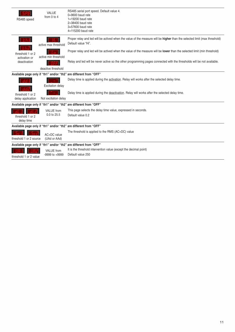
Available page only if “th1” and/or “th2” are different from “OFF”
The threshold is applied to the RMS (AC+DC) value
threshold 1 or 2 source
threshold 1 or 2 value
AC+DC value(UAd or AAd)
Available page only if “th1” and/or “th2” are different from “OFF”It is the threshold intervention value (except the decimal point)
Default value 250VALUE from
-9999 to +9999
threshold 1 or 2activation ordeactivation
active max threshold
active min threshold
deactive threshold
Proper relay and led will be actived when the value of the measure will be higher than the selected limit (max threshold)Default value “Hi”.
Proper relay and led will be actived when the value of the measure will be lower than the selected limit (min threshold)
Relay and led will be never active so the other programming pages connected with the thresholds will be not available.
Available page only if “th1” and/or “th2” are different from “OFF”
Delay time is applied during the activation. Relay will works after the selected delay time.
Delay time is applied during the deactivation. Relay will works after the selected delay time.threshold 1 or 2delay application
Excitation delay
Not excitation delay
Available page only if “th1” and/or “th2” are different from “OFF”
This page selects the delay time value, expressed in seconds.
Default value 0.2threshold 1 or 2delay time
VALUE from0.0 to 25.5
RS485 serial port speed. Default value 4.0=9600 baud rate1=19200 baud rate2=38400 baud rate3=57600 baud rate4=115200 baud rate
VALUEfrom 0 to 4
RS485 speed
app fotovoltaici 2010 GB:Contatori 08/10/10 12:56 Pagina 11

12
MULTIFUNCTION METERS
70
4585
58
LCD - 4 DIN MODULES D.C. VERSION DIMENSIONS in mm
PARAMETERSElectrical parameters 1RAEM4C 1RAEM4C 1RAEM4C 1RAEM4C 1RAEM4C 1RAEM4C 1RAEM4C 1RAEM4C
DC SDC 485DC S485DC HDC HSDC H485DC HS485DC- DC Voltage 800.0 V max • • • •- DC Voltage ..../100V by divider • • • •- DC Current .../60mV • • • • • • • •- Bidirectional power (kW) • • • • • • • •- Total active energy (Import) resettable parameter • • • • • • • •- Total active energy (Export) resettable parameter • • • • • • • •- Ampère-hour Ah+ (Import) resettable parameter • • • • • • • •- Ampère-hour Ah- (Export) resettable parameter • • • • • • • •- Total working hours • • • • • • • •- Partial working hours settable parameter • • • • • • • •- Indication of failed voltage supply • • • • • • • •- Programmed threshold V-A-W • • • •- Output relay NO (500mA/1000V) • • • •- Threshold activation signal • • • •- Threshold status summary page • • • •- Interface RS485 3kV optoinsulated 9600...115200bps • • • •- MODBUS SLAVE RTU full compliance • • • •- Remote configurable settings • • • •- Keypad configurable settings • • • • • • • •- Remote resetting of energies - ampere/hour - counter • • • •- Remote relay output control (if the threshold is OFF) • •- Configurable password for access to programming • • • • • • • •- Restore factory settings • • • • • • • •- Programming of initial page upon start-up • • • • • • • •- Programming of current 5 to 3000ADC with step of 5A • • • • • • • •- Programming of voltage from 10 to 3000.0VDC step 1V • • • •- Programming of analog average (VDC, ADC and W) • • • • • • • •- Download the software for free from our website www.revalco.it
- Weight kg 0,70- Sealable terminals cover included
GENERAL DESCRIPTIONThe 4 DIN instrument is suited for use in industrial and civil market, specially on sectors related to the production of alternative energy (photovoltaic, wind energy) .Simple and extremely compact, it features an alphanumerical display with 2 lines of eight-character lines, 6 auxiliary LEDS and 2 buttons for display selection and key-board programming. The machine is extremely user-friendly and information is presented clearly on the display. It is unlikely you will need to consult instruction manualwhich is not generally kept readily available at the site. When properly installed, the instrument measures the current from external shunt ..60mV. The instruments havethe possibility to select the current end scale value between 5,0 A to 3000 A DC by steps of 5,0A.Two principal families (direct and “H” insertion) forecast respectively the voltmeter measure in DC direct insertion ( -800,.0 / + 800,0 VDC) or by external voltage divi-der …../ 100VDC. Other executions can be manufactured on request ( ex. 24VDC, 48VDC, 150VDC etc) but must be considered as “special executions” with differentcosts. The instruments related to “H” family have the possibility to select the voltage end scale value between 10.0V to 3000 V DC by steps of 1,0V.The high accuracy class measures offered by each instrument are the most used on the DC field. Every direct measure (Voltage, Current and Power) is bidirectional; sothe inversion of polarity is shown and the measured range is the same in positive or negative case; practically if the end scale is 3000.0A, these instruments are able tomeasure from + 3000,0A to – 3000,0 ADC. The individually resettable Energies and Ampere Hour can be easily calculated when you need to service the system and/or periodical test line operation, determinezone consumption values, establish cost centres, etc.
NOTE: The instruments use simple Energy and Ampere Hour totalizing methods for purposes of diagnostics and statistics. These instruments can-not be considered as substitute of Energy kWhmeters.
The following are provided according to model: 1 threshold with output on “N.O.” control relay (500mA/1000V), fully programmable (model “S”)1 x RS485 3kV optoinsulated programmable high speed interface with MODBUS RTU protocol (model “RS485)
app fotovoltaici 2010 GB:Contatori 08/10/10 12:56 Pagina 12
13
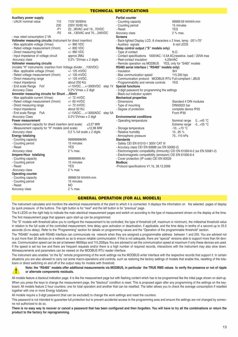
TECHNICAL SPECIFICATIONS
Partial counter- Counting capacity 99999:59 hhhhhh:mm- Counting period 15 minutes- Reset YESAccuracy class 2 % max.Screens- Back-lighted Display LCD, 8 characters x 2 lines, temp. -20°/+70°- Auxiliary signals 6 red LEDSRelay control output (“S” models only)- Type of contact N.O.- Contact specifications 1000VAC / 0.5A AC(resistive. load) / 20VA max- Reel-contact insulation 4.25kVAC- Remote operation via MODBUS YES, only for “S485” modelsRS485 serial interface ( “RS485” models only)- Insulation 3kV- Max communication speed 115.200 bps- Communication protocol MODBUS RTU Full-compliant / JBUS- Programmability and remote controls YESSpecial functions- 3-digit password for programming the settings- Black-out indicator systemMechanical properties- Dimensions Standard 4 DIN modules- Type of mounting DIN50022 bar- Degree of protection complete device IP20
Front IP30Environmental conditions- Operating temperature: Nominal range 0...+45 °C
Extreme range -5...+55 °C- Storage temperature -10...+70 °C- Relative humidity 10...95 %- Atmospheric pressure 70...110 kPaStandards - Safety CEI EN 61010-1 300V CAT III- Accuracy class CEI EN 60688 (ex EN 50082-2)- Electromagnetic compatibility (immunity) CEI EN 61000-6-2 (ex EN 50081-2)- Electromagnetic compatibility (emission) CEI EN 61000-6-4- Cover protection (IP code) CEI EN 60529Modbus:-Protocol specifications V1.1b, 28.12.2006
Auxiliary power supply- UAUX nominal value 110 110V 50/60Hz
230 230V 50/60 Hz-P1 22...36VAC and 19...70VDC-P2 44...130VAC and 70....240VDC
- max rated consumption 2 VAVoltmeter measuring circuits (instrument for direct insertion)- Max applicable voltage (Vmax) +/- 960 VDC - Rated voltage measurement (Vnom) +/- 800 VDC - Direct measuring field +/- 960 VDC - Input impedance of voltage circuit approx 2MΩ -Accuracy class 0.2% *2Vmax ± 2 digitsVoltmeter measuring circuits(models “H” instruments; insertion from Voltage divider… /100VDC)- Max. applicable voltage (Vmax) +/- 125 mVDC- Rated voltage measurement (Vnom) +/- 100 mVDC- Direct measuring range +/- 125 mVDC.- Imput impedance about 250 KΩ - End scale Range FsV +/-10VDC.....+/-3000VDC step 1V-Accuracy Class 0.2%*Vmax ± 2 digitAmmeter measuring circuits for Shunt …/60mV- Max applicable current (Vmax) +/- 72 mVDC- Rated voltage measurement (Vnom) +/- 60 mVDC- Direct measuring range +/- 72 mVDC.- Imput impedance about 50 KΩ - End scale Range FsA +/-15ADC.....+/-3000ADC step 5A-Accuracy Class 0.2%*2Vmax ± 2 digitPower measurement- Measurement capacity for direct insertion (end scale) ±3,57 MW - Measurement capacity for “H” models (end scale) ±12,96 MW -Accuracy class 0,5 % full scale ± 2 digitsEnergy totalizing- Counting capacity 99999999kWh - Counting period 15 minutes- Reset YES-Accuracy class 2 % max.Ampere-Hour totalizing- Counting capacity 99999999 Ah - Counting period 15 minutes- Reset YES-Accuracy class 2 % max.Operating counter- Counting capacity 99999:59 hhhhhh:mm- Counting period 15 minutes- Reset NOAccuracy class 2 % max.
GENERAL OPERATION (FOR ALL MODELS)The instrument calculates and monitors the electrical measurements of the plant to which it is connected. It displays the information on the selected pages of displayby quick pressure of the buttons. The right button is for “next” and the left button is for “previous” page. The 6 LEDS on the right help to indicate the main electrical measurement pages and switch on according to the type of measurement shown on the display at the time. The first measurement page that appears upon start-up can be programmed. The “S” models with threshold allow you to configure the measurement to be controlled, the type of threshold (off, maximum or minimum), the millesimal threshold valuein relation to the full scale of the controlled measurement, time delay upon activation or deactivation, if applicable, and the time delay in tenths of a second up to 25.5seconds (0=no delay). Refer to the “Programming” section for details on programming values and the “Operation of the programmable threshold” section.The “RS485” models with RS485 interface can communicate via network when they are assigned a programmable address between 1 and 255. You are advised notto put more than 32 devices on a network so as to ensure reliable communication. If this is not adequate, there are “special” versions able to support more than 64 devi-ces. Communication speed can be set at between 9600bps and 115,200bps.You are advised to set the communication speed at maximum if only these devices are used.If the speed is set too low and there are frequent requests and/or there is a high number of required records, interactions with the instrument may also slow down.Allmeasurements and parameters can be viewed on the MODBUS RTU reader interface.The instrument also enables “on the fly” remote programming of the work settings via the MODBUS writer interface with the respective records that support it. In certainsituations you are also allowed to carry out some macro-operations and controls, such as restoring the factory settings of models that enable this, resetting of the tota-lizers or direct switching on and off of the output relay for models with threshold.
Note: the “RS485” models offer additional measurements via MODBUS, in particular the TRUE RMS values to verify the presence or not of rippleor alternate components residuals.
All models feature a blackout indication page. It is like the measurement page but with flashing content which has to be programmed like the initial page shown on start-up.When you press the keys to change the measurement page, the “blackout” condition is reset. This is proposed again after any programming of the settings on the key-board. All models feature 2 hour counters; one for total operation and another that can be resetted. The latter allows you to check the average consumption if resettedtogether with one or more Energy totalizers.All models require a 3-digit password (that can be excluded) to change the work settings and reset the counters.This password is not intended to guarantee full protection but to prevent accidental access to the programming area and ensure the settings are not changed by someo-ne not authorized to do so.There is no easy way to recover or cancel a password that has been configured and then forgotten. You will have to try all the combinations or return theproduct to the factory for reprogramming.
app fotovoltaici 2010 GB:Contatori 08/10/10 12:56 Pagina 13

14
OPERATION
When you start up the device, the firmware information page appears for a few seconds and all the LEDS switch on in sequence (initial diagnostics).You will then see, for a few seconds, the page with the “title” of the measurements that will appear on the display, and the respective LED will switch on if the page requi-res it to do so. When the first measurement page appears, you can press the buttons to scroll through the available pages.You can scroll FORWARDS by QUICKLY PRESSING the RIGHT-HAND button, or BACKWARDS by pressing the LEFT-HAND button.Pressing and holding the right-hand button will take you to the next page as well as allow you to program the instrument’s settings.Pressing one of the 2 buttons quickly displays the “title” of the measurement page to be displayed
1RAEM4C DC / ...SDC / ...485DC / ...S485DC1RAEM4C HDC / ...HSDC / ...H485DC / ...HS485DC
The measurement and indication pages which can be accessed by pressing and Quickly releasing the RIGHT-HAND button are the follows:
03.12.0884.00.00
Appears only for about 3 seconds when the instrument is switched on.Provides information on the instrument’s firmware and operating details.When this page is displayed, the LEDS flash quickly to indicate they are working properly.
PowerOnReady
Black-out page. For this to appear, it has to be configured as the default page.Appears only when the instrument is switched on. It disappears as soon as the display is moved. It reappears after the settings are configured using the keypad.
RAECSDCH485:001
INFO page. Indicates the instrument model and version. The lightt-up square (first line on the right) indicates the voltage phases areOUT OF SEQUENCE. The square does not appear when the sequence is correct. Only in the case of the “RS485” models does the last valueat the bottom on the right indicate the node number of the instrument on the MODBUS network.
DC Voltage measure
Volt DC Volt DC100.0
Value of DC Voltage component, with + or - (V)
DC Current measure
Amp DC Amp DC-100.0
Value of DC Current component, with + or - (A)
DC Power measure
kW DC kW DC-10.00
Value of DC Power component, with + or - (kW)
Positive Energy totalizing
Total positive Energy (kWh)
PRESSED BUTTON WHEN RELEASED DESCRIPTION
kWh+ kWh+ 78973588
Negative Energy totalizing
Total negative Energy (kWh)kWh- kWh-
1347
Positive Ampere-hour totalizing
Total positive Ampere-hour (Ah)Ah+ Ah+
1546170
Negative Ampere-hour totalizing
Total negative Ampere-hour (Ah)Ah- Ah-
2723
Total counter
Operating time in hours and minutes (hhhhh:mm)T Time T Time
97163:58
NOTES AND OPERATING INSTRUCTIONS
DO NOT PRESS ANY OF THE KEYS while switching on the instrument (i.e. when connecting it to the auxiliary power supply).
Otherwise you may accidentally start the calibration procedure normally carried out at the factory which, if the instrument is connected to the system rather than to therespective calibration devices, could cause the instrument to be permanently not calibrated.
In the interest of safety, ALWAYS WAIT FOR THE INITIAL DIAGNOSTICSTO FINISH (scanning of the LEDS) before pressing any of the keys.
“S” instruments with threshold: The threshold relay is blocked for the first ten seconds after the instrument is switched on.The relay is “frozen” until you have finished configuring the settings.
app fotovoltaici 2010 GB:Contatori 08/10/10 12:56 Pagina 14

15
OPERATION OF THE PROGRAMMABLE THRESHOLD (“S” models only). These models allow you to apply a max or min threshold as a percentage of the requiredsize, in relation toits intended full scale.
The threshold activation (threshold active) point is the condition “more than Th1 Val” if Th1 Sel = Hi; otherwise “less than Th1 Val” if Th1 Sel = LoThe threshold’s quiescent operating (threshold inactive) point is the condition “less than or equal to Th1 Val” if Th1 Sel=Hi; otherwise “more than or equal to Th1 Val”
if Th1 Sel=Lo.
The “active threshold” condition attempts to CLOSE the relay’s “N.O.” contacts and this occurs instantly unless there is the delay Th1 Dly if Th1 DD is “Off-On”The “inactive threshold” condition attempts to OPEN the relay’s “N.O.” contacts and this occurs instantly unless there is the delay Th1 Dly if Th1 DD is “On-Off”.
There are 2 cases whereby the output relay does NOT mirror the threshold condition. These are as follows:- During the first 10 seconds from starting up the instrument, when the relay is kept inactive to avoid unwanted operation while the measurements are stabilized, and- when the settings are being programmed on the keypad, it is kept at the same status at the time of starting the procedure, to prevent partial modification of the set-
tings from causing unwanted change to its status.Relay status is shown on the display at page “OUT”, together with the title of the size of the threshold selected in Th1 Src.Closing of the relay also determines flashing of the LED associated with the selected size (when applicable), providing the selected measurement page is not the one associated with the LED, in which case the LED light remains steady.
“RS485” Models: when Th1 Sel=OFF (threshold OFF), there is the option of controlling the relay directly by means of MODBUS commands to open and closeINSTANTLY, regardless of the Th1 Dly and Th1 DD settings. “Src=REM”(REMOTE) appears on the OUT page to indicate remote access of the relay.
Required parameter (Th1 Src) Full scale (= 100.0%) DescriptionkW+ FsA * FsV Max/Min instantly consumed positive Active PowerkW- FsA * FsV Max/Min instantly consumed negative Active PowerA+ FsA Max/Min positive currentA- FsA Max/Min negative currentV+ FsV Max/Min positive voltageV- FsV Max/Min negative voltage
0
OFFON
- Hi + 0
OFF ON
- Lo +
0
OFF ON
- Hi + 0
OFFON
- Lo +
Partial counter
Time since last reset, in hours and minutes (hhhhh:mm)R Time R Time
80445:21
Relay
FOR “S” MODELS ONLYStatus of output relay contact (On=closed) and source of the thresholdOut Out= On
Src= Wt
Indicates you have entered the setting configuration phase.
A password is only requested if NewPassw is set at a value other than 0 (see below).Select the correct number and wait for the next page. In the case of a missing or incorrect entry, the instrument returns to normal operationafter about 4 seconds.
By pressing a key when this page is shown, all value parameters return equal to the factory programming, except totalizer resetting oneby one.
To set the Current end scale value (…./60mVDC)in Ampere. Settable between 5 and 3000 at steps of 5Default = 100
PROGRAMMING
For programming, press and hold the RIGHT-HAND button (for 4 seconds or more). The first page to appear when you are granted access to the programming mode isthe one of programmable values. Releasing the button will make the display flash (to indicate you are in programming mode) and the pages begin to scroll through slowly(one every 4 seconds or so), indicating the title and value of the current set-point. If you do not touch the button when you get the last page, normal operation is resto-red without saving any changes. To make a change, simply press one of the buttons when the required page appears, respectively:LEFT-HAND button = DECREASES the value; RIGHT-HAND button = INCREASES the value.At that point (after pressing the button) the display remains steady so you can check the modification and the value changes by one unit. If you have to modify a valuequite considerably, you can press and hold the button for more than 2 seconds to speed up the process. The longer you hold down the button, the faster you can scrollthrough the numbers (4 speeds). They are all “roll” values so when you get to the maximum permitted value you restarted from the minimum value, and vice versa. Whenyou have set the value as required, release the button and wait for over 4 seconds. The pages then continue scrolling and the modification is automatically saved.Modifiable pages then follow.
ProgramMode
Password000
DefaultParam
FsA Set100
app fotovoltaici 2010 GB:Contatori 08/10/10 12:56 Pagina 15

16
THE WINDOWS BELOW APPLY ONLY TO THE “S” MODELS
Selecting the threshold operation mode. Settable between: Hi=High threshold, Lo=Low threshold and Off=threshold disabled.If the threshold is OFF, you will not view the following pages. Default = Hi (high threshold).
Delay time for activation of the output relay (page displayed only if Th1 Sel is not Off)Expressed in seconds. Settable between 0.0 and 25.5 in steps of 0.1. Default = 0.1
Assigning the delay time for activating the threshold (page displayed only if Th1 Sel is not Off)The delay time is applicable from the start of threshold activation (Off-On) or at the end (On-Off). Default = Off-On (at the start)
Assigning the size for activating the threshold (page displayed only if Th1 Sel is not Off)Settable at: kW +, k W -, V+, V-, A +, A -. Default =k W+
Regulating the threshold value as a At the top is the effective value of the threshold for the percentage of the full scale selected parameter. Settable between: 0.0 and 100.0, in (page displayed only if Th1 Sel is not Off) steps of 0.1. Default = 50.0 (%)
THE WINDOWS BELOW APPLY ONLY TO THE “485” MODELSAssigning the MODBUS address node number Configuring the speed of the RS485 serial port (bps)(of the “INFO”, ADR: nnn page). Settable between 0 and 4 (0=9600, 1=19200, 2=38400,Settable between 1 and 255. Default = 1 3=57600, 4=115200). Default = 4
THE WINDOWS BELOW APPLY ONLY TO THE “H” MODELSTo select the Voltage end scale value from voltage divider. Selectable from 10.0V to 3000 V DC by steps of 1,0V.Default=100
Average of the analogue values measured (V, A and P). To stabilize the displayed values. More higher is the number, more stable are the measurements , although they will be slow to update. Settable between 1 and 15 at steps of 1. Default = 25
Configuration of the first measurement page to be viewed upon start-up. Using the buttons to scroll through displays the “titles” of the available pages – the same ones that appear when you press the right-hand button in sequence.Settable on all the available pages. Default = Blackout detection page
Setting this at zero disables password protection for programming with the keypad. The same applies for password protection for programming by remote control. Settable between 0 and 999 at steps of 1.Default = 0 (disabled)
Resetting the Totalizer Pressing and holding the right-hand button for moreof positive Energy than 4 seconds, the value will be resetted
Resetting the Totalizer Pressing and holding the right-hand button for moreof negative Energy Pressing than 4 seconds, the value will be resetted
Resetting the Totalizer Pressing and holding the right-hand button for moreof positive Ampere-hour than 4 seconds, the value will be resetted
Resetting the Totalizer Pressing and holding the right-hand button for more.of negative Ampere-hour than 4 seconds, the value will be resetted
Resetting the Partial counter Pressing and holding the right-hand button for morethan 4 seconds, the value will be resetted
FsV Set100
Average25
DefaultPage
NewPassw0
kWh+ ->078973588
kWh- ->01347
kWh+ ->00
kWh- ->00
R Time->080445:21
5.00kW+ 50.0
Ah+ ->01546170
Th1 SelHi
Th1 Dly0.1
Th1 DDOff-On
Th1 SrcW+
Node1
Th1 Val%kW+ 50.0
Speed4
R Time->00:00
Ah+ ->00
Ah- ->02723
Ah- ->00
CONNECTION DIAGRAM
-+ +
-
+-
+-
shunt .../60mV
0,5A-1000V20VA
N.O.C
Option for “485”version
Option for “S”
version
app fotovoltaici 2010 GB:Contatori 08/10/10 12:56 Pagina 16

17
kWh-METERSFOR DIRECT CURRENT
1 4
-+
LOAD
+
-
+-
60mV
shunt 48V DC
open-collector - max 36V / 20mA DC
100 ms
t
3
76
1RCEM2CBURDEN < 4WPOWER SUPPLY 48V DC (40 ÷ 54 V DC) selfsuppliedACCURACY CLASS 2TEMPERATURE functioning -5°C ÷ +50°C / storage -25°C ÷ +70°CREADING RESOLUTION 0,01 kWhDISPLAY 99999,99 kWh (5 entires + 2 decimals)SIGNALLING LED yellow OFF = correct connection
yellow ON = wrong connectionit is necessary to check the measuring circuit connections, if the connection is inverted, the numbererwill block and stop counting until the anomaly is resolved
red flashing = active consumption NOMINAL CURRENT DC from external shunt (....A/60mV)The value of primary current must be indicated during the order between:30A - 40A - 50A - 60A - 80A - 100A - 120A - 150AMAXIMUM ADMITTED CURRENT 1,2 InOUTPUT IMPULSES Open-Collector System (SO, DIN43864),
max 36V/20mA DC - Impulse duration 100 msDIMENSIONS / WEIGHT kg. 2 DIN modules / 0,13
Connection sequence:1- Connect the shunt.....A/60mV2- Make the other connections
ONE OUTPUT RELAY
MULTIVOLTAGE RELAYS1RMR1Wide voltage coil range for every application in VDC or VAC, range from 12....400VDC and 12....270VAC for electricalmaintenance or new installation not depending by the voltage supply and electrical photovoiltaic applications.Low consumption 0.4W for pick up time; 0.2W all working time
- SAFETY APPROVALS – STANDARD EN61010-1 / EN61810-1..ec..-2- COIL CONSUMPTION <0.2W TRMS for all voltage supply - NOMINAL FREQUENCY VOLTAGE DC or from 49Hz to 600Hz- TEMPERATURE operative range -20....+55°C
storage -25....+70°C- RELAY led light = relay on- CONTACT RATING (Inom) 8 A, AC resistive load 250VAC
6 A, DC resistive load 125VDC- DIELECTRIC STRENGTH 5000 Vrms
Power Supply
N.C.
N.O. C
TWO OUTPUT RELAYS
1RMR2Wide voltage coil range for every application in VDC or VAC, range from 12....400VDC and 12....270VAC for electricalmaintenance or new installation not depending by the voltage supply and electrical photovoiltaic applications.Low consumption 0.4W for pick up time; 0.2W all working time
- SAFETY APPROVALS – STANDARD EN61010-1 / EN61810-1..ec..-2- COIL CONSUMPTION <0.2W TRMS for all voltage supply - NOMINAL FREQUENCY VOLTAGE DC or from 49Hz to 600Hz- TEMPERATURE operative range -20....+55°C
storage -25....+70°C- RELAY led light = relay on- CONTACT RATING (Inom) 8 A, AC resistive load 250VAC
6 A, DC resistive load 125VDC- DIELECTRIC STRENGTH 5000 Vrms Power Supply
Relay 2
Relay 1
app fotovoltaici 2010 GB:Contatori 08/10/10 12:56 Pagina 17

18
MEASUREMENT TRANSDUCERS - TRUE RMS
SINGLE PHASE
Auxiliary power supply: see table Selectable output nominal values 1-5-10VDC and 1-5-10-20-4/20mADCInput nominal values: see table ±1, ±5, ±10 VDC and ±1, ±5, ±10, ±20, 4/20 mA DCResponse time ≤ 300 ms Class 0,5Dimensions: 2 DIN modules Transparent sealable front coverResistive load: 700Ω
1COR2A...•
••••
1COR2V...
•
••••
1COR2C...
•••••
Current transducers 230Voltage transducers 230DC line power transducers 230Sole power supply 24VAC 24Sole power supply 110VAC 110Sole power supply 22...36VAC and 19...70VDC -P1Sole power supply 44...130VAC and 70...240VDC -P2
1COR2A... 1COR2V... 1COR2C....
CODES TABLE
1 C O R 2 A 2 3 0 - 1 A C
2 D
IN m
odul
estra
nsdu
cers
iden
tific
atio
n
mea
surin
gun
it
inpu
t
pow
er s
uppl
y
230 = 230VAC-24 = 24VAC110 = 110VAC-P1 = 22...36VAC and 19...70VDC-P2 = 44...130VAC and 70...240VDC
A = currentV = voltageC = DC line power
-5DC = input 5A DC-10DC = input 10A DC-60MV = input 60mV DC (or -100MV / -150MV / -300MV)
-500V = input 500V AC or DC-100V = input 100V AC or DC-110V = input 110V AC or DC-150V = input 150V AC or DC-250V = input 250V AC or DC100R3V = input 100V: 3 AC or DC110R3V = input 110V: 3 AC or DC
-5A50V = calibration 5A 50V DC(voltage/current measure has a common point)
Power supply
Signal input (mV)
mA DCmA DCmA DCmA DCmA DC
V DCV DCV DC
+-+ -
Powersupply
AC /DC Signal input (V)
mA DCmA DCmA DCmA DCmA DC
V DCV DCV DC
+ -
V)
Powersupply
DC Signal input (50V)
mA DCmA DCmA DCmA DCmA DC
V DCV DCV DC
DC Signal input (mV)
+-+ -
POSITIVE SELECTABLE OUTPUTS
1 2 3 4 5 6 7 8 9 10 1 2 3 4 5 6 7 8 9 10
POSITIVE / NEGATIVE SELECTABLE OUTPUTS
1 2 3 4 5 6 7 8 9 10 1 2 3 4 5 6 7 8 9 10
4(-)12(0) mA20(+)
app fotovoltaici 2010 GB:Contatori 08/10/10 12:56 Pagina 18

19
MEASUREMENT TRANSDUCERSCURRENT
EXTERNAL POWER SUPPLY 1CORIC
- AUXILIARY SUPPLY (separate) 230V AC standard- NOMINAL INPUT VALUES 1A and 5A present on the same transducer- NOMINAL OUTPUT VALUES (selectable) 1 - 5 - 10 VDC and 1 - 5 - 10 - 20 - 4/20 mA DC- RESISTIVE LOAD 700Ω- MEASURING RANGE 0 ÷ In- ACCURACY CLASS 0,5- OVERLOAD Permanent: 2 In Instantaneous: 10 In for 1 sec.- RESPONSE TIME ≤ 300 ms- ALTERNATED RESIDUAL ≤ 1%- OPERATING FREQUENCY 50/60 Hz- BURDEN current circuit: ≤ 0,8 VA - power supply: ≤ 4VA- GALVANIC SEPARATION BETWEEN INPUTS AND OUTPUTS
• insulation between inputs, outputs, power supply 2kV for 1min at 50Hz• insulation between the all circuits and earth 4kV for 1min at 50Hz
- OPERATING TEMPERATURE 0 °C ÷ +55 °C- INPUT WAVE FORM OS- DIMENSIONS / WEIGHT Kg. 6 DIN modules (3 DIN modules) / 0,54 (0,27)- Different technical characteristic can be considered, under specific requests
VOLTAGEEXTERNAL POWER SUPPLY 1CORUC
- AUXILIARY SUPPLY (separate) 230V AC standard- NOMINAL INPUT VALUES to be specified when ordering- NOMINAL OUTPUT VALUES (selectable) 1 - 5 - 10 VDC and 1 - 5 - 10 - 20 - 4/20 mA DC- RESISTIVE LOAD 700Ω- MEASURING RANGE 0 ÷ In- ACCURACY CLASS 0,5- OVERLOAD Permanent: 2 In Instantaneous: 10 In for 1 sec.- RESPONSE TIME ≤ 300 ms- ALTERNATED RESIDUAL ≤ 1%- OPERATING FREQUENCY 50/60 Hz- BURDEN current circuit: ≤ 0,8 VA - power supply: ≤ 4VA- GALVANIC SEPARATION BETWEEN INPUTS AND OUTPUTS
• insulation between inputs, outputs, power supply 2kV for 1min at 50Hz• insulation between the all circuits and earth 4kV for 1min at 50Hz
- OPERATING TEMPERATURE 0 °C ÷ +55 °C- INPUT WAVE FORM OS- DIMENSIONS / WEIGHT Kg. 6 DIN modules (3 DIN modules) / 0,54 (0,27)- Different technical characteristic can be considered, under specific requests
The selection of the required output is achieved by adju-sting the minidip keys as described in the following dia-gram:
Where a Voltage output is required connection is byterminal N 13 and 14; for Current output connect toterminals N 17 and 18.
The selection of the required output is achieved by adjustingthe minidip keys as described in the following diagram:
Where a Voltage output is required connection is by termi-nal Nos, 13 and 14 and for Current output connect to termi-nal Nos, 17 and 18.
10 V DC5 V DC1 V DC
4÷20 mA DC20 mA DC10 mA DC5 mA DC1 mA DC
13 14 17 18
+- +-
Input signal60 mV+
7 8 10 12
- +
Power supply
10 V DC5 V DC1 V DC
4÷20 mA DC20 mA DC10 mA DC5 mA DC1 mA DC
13 14 17 18
+- +-
7 8 10 12
- +Power supply + Input
signal (V)
When ordering it isnecessary to specify
the required inputsignal
app fotovoltaici 2010 GB:Contatori 08/10/10 12:56 Pagina 19
20
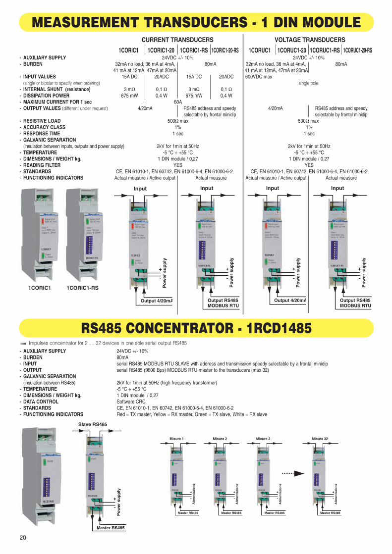
1CORIC1 1CORIC1-20 1CORIC1-RS 1CORIC1-20-RS 1CORUC1 1CORUC1-20 1CORUC1-RS 1CORUC1-20-RS- AUXILIARY SUPPLY 24VDC +/- 10% 24VDC +/- 10%- BURDEN 32mA no load, 36 mA at 4mA, 80mA 32mA no load, 36 mA at 4mA, 80mA
41 mA at 12mA, 47mA at 20mA 41 mA at 12mA, 47mA at 20mA- INPUT VALUES 15A DC 20ADC 15A DC 20ADC 600VDC max
(single or bipolar to specify when ordering) single pole- INTERNAL SHUNT (resistance) 3 mΩ 0,1 Ω 3 mΩ 0,1 Ω- DISSIPATION POWER 675 mW 0,4 W 675 mW 0,4 W- MAXIMUM CURRENT FOR 1 sec 60A- OUTPUT VALUES (different under request) 4/20mA RS485 address and speedy 4/20mA RS485 address and speedy
selectable by frontal minidip selectable by frontal minidip- RESISTIVE LOAD 500Ω max 500Ω max- ACCURACY CLASS 1% 1%- RESPONSE TIME 1 sec 1 sec- GALVANIC SEPARATION
(insulation between inputs, outputs and power supply) 2kV for 1min at 50Hz 2kV for 1min at 50Hz- TEMPERATURE -5 °C ÷ +55 °C -5 °C ÷ +55 °C- DIMENSIONS / WEIGHT kg. 1 DIN module / 0,27 1 DIN module / 0,27- READING FILTER YES YES- STANDARDS CE, EN 61010-1, EN 60742, EN 61000-6-4, EN 61000-6-2 CE, EN 61010-1, EN 60742, EN 61000-6-4, EN 61000-6-2- FUNCTIONING INDICATORS Actual measure / Active output Actual measure Actual measure / Active output Actual measure
CURRENT TRANSDUCERS VOLTAGE TRANSDUCERS
1CORIC1 1CORIC1-RS
Output RS485MODBUS RTU
Input
+
-
Po
wer
su
pp
ly
Output RS485MODBUS RTU
Input
+
-
Po
wer
su
pp
ly
Output 4/20mA
Input
+
-
Po
wer
su
pp
lyOutput 4/20mA
Input
+
-
Po
wer
su
pp
ly
MEASUREMENT TRANSDUCERS - 1 DIN MODULE
RS485 CONCENTRATOR - 1RCD1485- AUXILIARY SUPPLY 24VDC +/- 10%- BURDEN 80mA- INPUT serial RS485 MODBUS RTU SLAVE with address and transmission speedy selectable by a frontal minidip- OUTPUT serial RS485 (9600 Bps) MODBUS RTU master to the transducers (max 32)- GALVANIC SEPARATION
(insulation between RS485) 2kV for 1min at 50Hz (high frequency transformer)- TEMPERATURE -5 °C ÷ +55 °C- DIMENSIONS / WEIGHT kg. 1 DIN module / 0,27- DATA CONTROL Software CRC- STANDARDS CE, EN 61010-1, EN 60742, EN 61000-6-4, EN 61000-6-2- FUNCTIONING INDICATORS Red = TX master, Yellow = RX master, Green = TX slave, White = RX slave
Impulses concentrator for 2 .... 32 devices in one sole serial output RS485
Master RS485
Slave RS485
+
-
Po
wer
su
pp
ly
Master RS485
Misura 1 Misura 2 Misura 3 Misura 32
+
-
Alim
enta
zio
ne
Master RS485
+
-
Alim
enta
zio
ne
Master RS485
+
-
Alim
enta
zio
ne
Master RS485
+
-
Alim
enta
zio
ne
app fotovoltaici 2010 GB:Contatori 08/10/10 12:56 Pagina 20
21
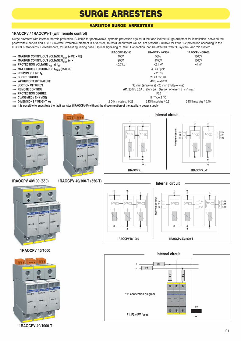
SURGE ARRESTERSVARISTOR SURGE ARRESTERS
1RAOCPV / 1RAOCPV-T (with remote control)Surge arresters with internal thermis protection. Suitable for photovoltaic systems protection against direct and indirect surge arresters for installation between thephotovoltaic panels and AC/DC inverter. Protective element is a varistor, so residual currents will be not present. Suitable for zone 1-2 protection according to theIEC62305 standards. Policarbonate, V0 self-extinguishing case. Optical signalling of fault. Connection can be effected with "T" system and "V" system.
1RAOCPV 40/100 1RAOCPV 40/550 1RAOCPV 40/1000MAXIMUM CONTINUOUS VOLTAGE Ucpv (+ PE, - PE) 100V 550V 1000VMAXIMUM CONTINUOUS VOLTAGE Ucpv (+ - ) 200V 1100V 1000VPROTECTION VOLTAGE Up at In <0,7 kV <2,1 kV <4 kVMAX CURRENT DISCHARGE Imax (8/20 µs) 40 kA / poloRESPONSE TIME tA < 25 nsSHORT CIRCUIT 25 kA / 50 HzWORKING TEMPERATURE -40°C ÷ +80°CSECTION OF WIRES 35 mm2 (single wire) - 25 mm2 (multiple wire) REMOTE CONTROL AC: 250V / 0,5A ; 125V / 3A Section of wire 1,5 mm2 maxPROTECTION DEGREE IP20CLASS (IEC / EN / VDE) II / Type 2 / CDIMENSIONS / WEIGHT kg 2 DIN modules / 0,28 2 DIN modules / 0,31 3 DIN modules / 0,40It is possible to substitute the fault varistor (1RAOCPV-F) without the disconnection of the auxiliary power supply
PE
+ -
PE
+ -
F1F1
+
-
F2
F2
PE
Internal circuit
Internal circuit
1RAOCPV...-TR
emo
te c
on
tro
l
1RAOCPV 40/100 (550) 1RAOCPV 40/100-T (550-T)
1RAOCPV 40/1000
1RAOCPV 40/1000-T
1RAOCPV...
+ PE - + PE -
Internal circuit
1RAOCPV40/1000-T
Rem
ote
co
ntr
ol
1RAOCPV40/1000
“T” connection diagram
F1, F2 = PV fuses
app fotovoltaici 2010 GB:Contatori 08/10/10 12:56 Pagina 21
22
+
T.C.
-
T.C.
PE
1411
12
+
T.C.
-
T.C.
PE
Internal circuit
1RAOSAFE C-T...PV
Rem
ote
co
ntr
ol
1RAOSAFE C...PV1RAOSAFE C-T 75...1000PV
1RAOSAFE C 1200PV
1RAOSAFE C 75...1000PV
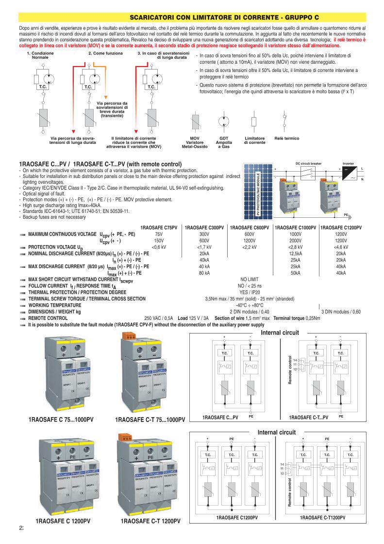
1RAOSAFE C...PV / 1RAOSAFE C-T...PV (with remote control)- On which the protective element consists of a varistor, a gas tube with thermic protection.- Suitable for installation in sub distribution panels or close to the main device offering protection against indirect
lighting overvoltages. - Category IEC/EN/VDE Class II - Type 2/C. Case in thermoplastic material, UL 94-V0 self-extinguishing. - Optical signal of fault.- Protection modes (+) + (-) - PE, (+) - PE / (-) - PE. MOV protective element. - High surge discharge rating Imax=40kA. - Standards IEC-61643-1; UTE 61740-51; EN 50539-11.- Backup fuses are not necessary
1RAOSAFE C75PV 1RAOSAFE C300PV 1RAOSAFE C600PV 1RAOSAFE C1000PV 1RAOSAFE C1200PVMAXIMUM CONTINUOUS VOLTAGE Ucpv (+ PE, - PE) 75V 300V 600V 1000V 1200V
Ucpv (+ - ) 150V 600V 1200V 2000V 1200VPROTECTION VOLTAGE Up <0,6 kV <1,7 kV <2,2 kV <2,8 kV <4,6 kVNOMINAL DISCHARGE CURRENT (8/20µs) In (+) - PE / (-) - PE 20kA 12,5kA 20kA
In (+) + (-) - PE 40kA 25kA 20kAMAX DISCHARGE CURRENT (8/20 µs) Imax (+) - PE / (-) - PE 40 kA 25kA 40kA
Imax (+) + (-) - PE 80 kA 50kA 40kAMAX SHORT CIRCUIT WITHSTAND CURRENT Iscwpv NO LIMITFOLLOW CURRENT If / RESPONSE TIME tA NO / < 25 nsTHERMAL PROTECTION / PROTECTION DEGREE YES / IP20TERMINAL SCREW TORQUE / TERMINAL CROSS SECTION 3,5Nm max / 35 mm2 (solid) - 25 mm2 (stranded) WORKING TEMPERATURE -40°C ÷ +80°CDIMENSIONS / WEIGHT kg 2 DIN modules / 0,40 3 DIN modules / 0,60REMOTE CONTROL 250 VAC / 0,5A Load 125 V / 3A Section of wire 1,5 mm2 max Terminal torque 0,25NmIt is possible to substitute the fault module (1RAOSAFE CPV-F) without the disconnection of the auxiliary power supply
1RAOSAFE C-T 1200PV
+
T.C. T.C.
-
T.C.
PE
1411
12
+
T.C. T.C.
-
T.C.
PE
Internal circuit
1RAOSAFE C-T1200PV
Rem
ote
co
ntr
ol
1RAOSAFE C1200PV
InverterDC circuit breaker
L
N
+
-
+
-
PEPV
PH
OTO
VO
LTA
IC M
OD
UL
E
SCARICATORI CON LIMITATORE DI CORRENTE - GRUPPO C
Dopo anni di vendite, esperienze e prove è risultato evidente al mercato, che il problema più importante da risolvere negli scaricatori fosse quello di annullare o quantomeno ridurre almassimo il rischio di incendi dovuti al formarsi dell’arco fotovoltaico nel contatto del relè termico durante la commutazione. In aggiunta al fatto che recentemente le nuove normativestanno prendendo in considerazione questa problematica, Revalco ha deciso di sviluppare una nuova generazione di scaricatori adottando una diversa tecnologia; il relè termico ècollegato in linea con il varistore (MOV) e se la corrente aumenta, il secondo stadio di protezione reagisce scollegando il varistore stesso dall’alimentazione.
T.C.T.C.T.C.
1. Condizione 2. Come funziona 3. In caso di sovratensioniNormale di lunga durata - In caso di sovra tensioni fino al 50% della Uc, poiché interviene il limitatore di
corrente ( attorno a 10mA), il variatore (MOV) non viene danneggiato.
- In caso di sovra tensioni oltre il 50% della Uc, il limitatore di corrente interviene aproteggere il relè termico
- Questo nuovo sistema di protezione (brevettato) non permette la formazione dell’arcofotovoltaico; l’energia che quindi attraversa lo scaricatore è molto bassa (I2 x T)
Via percorsa da sovra-tensioni di lunga durata
Il limitatore di correnteriduce la corrente che
attraversa il varistore (MOV)
MOVVaristore
Metal-Ossido
GDTAmpolla
a Gas
Limitatoredi corrente
Relè termico
Via percorsa dasovratensioni di
breve durata(transiente)
app fotovoltaici 2010 GB:Contatori 08/10/10 12:56 Pagina 22

23
Operative system “Open Loop (O/L)”The magnetic flux creaded by primary current IP, is concentradet in amagnetic circuit and measured on the open part of toroid by and Hallsensor. The signal exiting from this sensor is conditioned in the wayto represent exactly the primary current value.
This type of C.T. can be used as alternative to the shunts when high voltages are in the field and it is necesasry to have more higher galvanicseparations.
Function of sensor is based on “Hall effect” fisic principe:when a magnetic field is applied in a perpendicular way to a cable, atransverse voltage to the current flux direction is generated (Hall vol-tage).
Burden: < 2,5VAAuxiliary power supply 230VCA (12 - 24 - 48VDC on request)Response time 500 msecResistive load 500 ohm max
Testing voltage: 0,72kV/3kVSealable terminals cover includedDifferent characteristics on requestPositive and negative output (except secondary 4/20mA)
CURRENT TRANSFORMERS
GENERAL DESCRIPTION
Aux230 VAC
+_
InputA
Output4/20mA
Aux230 VAC
+_
Output4/20mA
CONNECTION DIAGRAM FOR TAHPD1 CONNECTION DIAGRAM FOR OTHER TAH...
A kgsecondary current
4/20mAsecondary current
20mAsecondary current
10V
code
151015
TAHPD1-1/4-20MATAHPD1-5/4-20MA
TAHPD1-10/4-20MATAHPD1-15/4-20MA
code
TAHPD1-1/20MATAHPD1-5/20MATAHPD1-10/20MATAHPD1-15/20MA
code
TAHPD1-1/10VTAHPD1-5/10VTAHPD1-10/10VTAHPD1-15/10V
class 1
prim
ary
curr
ent
0,5
wei
gth
A kgsecondary current
4/20mAsecondary current
20mAsecondary current
10V
code
202540
TAHPD1-20/4-20MATAHPD1-25/4-20MATAHPD1-40/4-20MA
code
TAHPD1-20/20MATAHPD1-25/20MATAHPD1-40/20MA
code
TAHPD1-20/10VTAHPD1-25/10VTAHPD1-40/10V
class 1
prim
ary
curr
ent
0,5
wei
gth
TAHPD1
3,7
60
55100
121
85
44
76
18,5
21Transformer with wound primary cable, primary and secondarycurrents on the terminals Fixing system: to wall by accessories supplied together with thecurrent transformerMomodirectional output
Base Mountingdimensions
“HALL” EFFECT
app fotovoltaici 2010 GB:Contatori 08/10/10 12:56 Pagina 23

24
TAHPD2
85
3,7
60
55
110 (135)
10,5
100
121
44
76
18,5
21
15 (25)
3(5)
Fixing system: to wall by accessories supplied togetherwith the current transformerTransformer with wound primary cable, primary currentfrom incorporated central bar15x3x110 mm up to 200A 25x3x135 mm up to 300A25x5x135 mm up to 400Asecondary currents on terminals
Base Mountingdimensions
A kgsecondary current
4/20mAsecondary current
20mAsecondary current
10V
code
506080100150
TAHPD2-50/4-20MATAHPD2-60/4-20MATAHPD2-80/4-20MATAHPD2-100/4-20MATAHPD2-150/4-20MA
code
TAHPD2-50/20MATAHPD2-60/20MATAHPD2-80/20MA
TAHPD2-100/20MATAHPD2-150/20MA
code
TAHPD2-50/10VTAHPD2-60/10VTAHPD2-80/10VTAHPD2-100/10VTAHPD2-150/10V
class 1
prim
ary
curr
ent
0,5
wei
gth
A kgsecondary current
4/20mAsecondary current
20mAsecondary current
10V
code
200250300400
TAHPD2-200/4-20MATAHPD2-250/4-20MATAHPD2-300/4-20MATAHPD2-400/4-20MA
code
TAHPD2-200/20MATAHPD2-250/20MATAHPD2-300/20MATAHPD2-400/20MA
code
TAHPD2-200/10VTAHPD2-250/10VTAHPD2-300/10VTAHPD2-400/10V
class 1
prim
ary
curr
ent
0,5
wei
gth
A kgsecondary current
4/20mAsecondary current
20mAsecondary current
10V
code
506080100150
TAH4D3-50/4-20MATAH4D3-60/4-20MATAH4D3-80/4-20MA
TAH4D3-100/4-20MATAH4D3-150/4-20MA
code
TAH4D3-50/20MATAH4D3-60/20MATAH4D3-80/20MATAH4D3-100/20MATAH4D3-150/20MA
code
TAH4D3-50/10VTAH4D3-60/10VTAH4D3-80/10VTAH4D3-100/10VTAH4D3-150/10V
class 1
prim
ary
curr
ent
0,7
wei
gth
A kgsecondary current
4/20mAsecondary current
20mAsecondary current
10V
code
200250300400
TAH4D3-200/4-20MATAH4D3-250/4-20MATAH4D3-300/4-20MATAH4D3-400/4-20MA
code
TAH4D3-200/20MATAH4D3-250/20MATAH4D3-300/20MATAH4D3-400/20MA
code
TAH4D3-200/10VTAH4D3-250/10VTAH4D3-300/10VTAH4D3-400/10V
class 1
prim
ary
curr
ent
0,7
wei
gth
A kgsecondary current
4/20mAsecondary current
20mAsecondary current
10V
code
100150200
TAH5-100/4-20MATAH5-150/4-20MATAH5-200/4-20MA
code
TAH5-100/20MATAH5-150/20MATAH5-200/20MA
code
TAH5-100/10VTAH5-150/10VTAH5-200/10V
class 1
prim
ary
curr
ent
0,5
wei
gth
A kgsecondary current
4/20mAsecondary current
20mAsecondary current
10V
code
250300400
TAH5-250/4-20MATAH5-300/4-20MATAH5-400/4-20MA
code
TAH5-250/20MATAH5-300/20MATAH5-400/20MA
code
TAH5-250/10VTAH5-300/10VTAH5-400/10V
class 1
prim
ary
curr
ent
0,5
wei
gth
30,5
10,6
30,5
10,6
25
3,7
60
45,5
2156
18,5
87
109
44
75
TAH4D3
Transformer suitable for primary current by cable with maximum dia-meter 25mm or horyzontal bar 30x10 mm; vertical bar 30x10 mmFixing system: - to wall or DIN rail by accessories
- directly to cable or busbar by screwsaccessories and screws are supplied together with the current tran-sformers
Screws M3,5x38
Base Mountingdimensions
DIN railaccessory
TAH5
Screws M3,5x38
3,7
60,7
54
34,2
21,4
25,3
31,3
12
34,3
52,1
42,2
2176
18,5
121
85
45
100
Transformer suitable for primary current by cable with maximum diameter30mm or bus bar: horyzontal 30x30 - 40x25 - 50x20 mm; vertical 30x10 mmFixing system: - to wall by accessories
- directly to cable or bus bar by screwsaccessories and screws are supplied together with the current transformer
Base Mountingdimensions
Central section
Central section
app fotovoltaici 2010 GB:Contatori 08/10/10 12:56 Pagina 24

25
RESISTANCE OF MANGANINE / TEMPERATURE
% V
AR
IAT
ION
OF
RE
SIS
TAN
CE + 0,04
+ 0,02
0
- 0,02
- 0,0420 30 40 50 60 70 80
TEMPERATURE °C
The purpose of the shunt is to permit the passage of the current which exceeds the capacity of the instrument. The latter will therefore be supplied only with acurrent which corresponds to its capacity, thus avoiding the risk of damaging the measuring equipment. The shunts are resistances of very little value and forthis reason they are at times formed by conductors with a bar of limited length and substantial rectangular section. For heat dissipation several bars in parallelare used, terminating in two clamps with a large contact surface. Alongside the two current clamps there are a further two clamps which serve to connect theammeter.These clamps have lesser section as the current necessary for the instrument is much lower than that of the shunt. Infact , it is not so much a que-stion of the shunt being parallel with the instrument as the instrument deriving from the clamps of the shunt, of which it utilizes the drop in voltage, withdrawinga part of the current of the circuit, proportionate with the total current.
STANDARDSElectrical characteristics: CENELEC HD 233, CEI 13-6, IEC 51, VDE 0410, BS 89, C 42-100Safety regulations: CENELEC HD 215, CEI 13-10, IEC 414, DIN 57410, BS 5458, C 42-010Dimensions DIN 43703
MATERIALSBody: Brass OT58 - UNI 4892Derivation with Manganina 43Accessories: zinc-iron 8.8
TEMPERATURESReferred temperature: 20°C ± 10°C respecting the precision of their classWorking temperature: -25°C ÷ +60°CStorage temperature: -40°C ÷ +80°CTemperature's coefficient: 0,002% for each °C
HUMIDITYRelative humidity of the ambient ≤ 95%
PRECISIONClass 0,5
OVERLOAD1,2 In continuously10 In for 5 seconds up to 250A5 In for 5 seconds from 300 to 2000A2 In for 5 seconds from 2500 to 6000A
GENERALStandard application: 60 mV and 150 mVThe 60mV shunts are used with a maximum load of 0,25 ohm ; in the case of greater loads or long connection cables, the 150mV shunts shouldbe used.Standards require the following primary values: 1 - 1,5 - 2,5 - 4 - 6 - 10 - 15 - 25 - 40 - 60 - 100 - 150 - 250 - 400 - 600 - 1000 - 1500 - 2500 -4000 - 6000 - 10000 - 15000 A. Primary values different from the standard can be manufactured on request.To ensure the unit functions perfectly Revalco insists the following points are observed:
1. They can be fitted in either a horizontal or vertical position (if horizontal there is a greater dissipation of heat)2. The contact surface must be completely used.3. The contact surface must be clean; after connecting, cover with special grease.4. The screws and bolts must be perfectly tightened.5. The shunts must be sufficiently ventilated.
Due the fact that the shunts are not insulated, it is better to protect them against accidental contacts.
CODES LEGENDCode SH1K0A60MV identify a 1000A/60mV shunt Code SH1K2A150MV identify a 1200A/150mV shuntCode SH1K5A60MV identify a 1500A/60mV shunt Code SH5K0A60MV identify a 5000A/60mV shuntCode SH10KA60MV identify a 10000A/60mV shunt
SHUNTS
TECHNICAL CHARACTERISTICS
app fotovoltaici 2010 GB:Contatori 08/10/10 12:56 Pagina 25

26
secondary 60 mV secondary 150 mV
DIMENSIONS in mm
SH750A60MV ÷ SH1K0A60MVFixing packs:2 screws M5x8 DIN 933 + 2 screws M20x50 DIN 933 + 2 nuts M20 DIN 934+ 2 washers M5 DIN 125A + 2 washers M20 DIN 125A+ 2 grower washers M20 DIN 127BWeight: 1,40 Kg
SH750A150MV ÷ SH1K0A150MVFixing packs:2 screws M5x8 DIN 933 + 2 screws M20x50 DIN 933 + 2 nuts M20 DIN 934+ 2 washers M5 DIN 125A + 2 washers M20 DIN 125A+ 2 grower washers M20 DIN 127BWeight: 1,55 Kg
SH400A60MV ÷ SH700A60MVFixing packs:2 screws M5x8 DIN 933 + 2 screws M16x45 DIN 933 + 2 nuts M16 DIN 934+ 2 washers M5 DIN 125A + 2 washers M16 DIN 125A+ 2 grower washers M16 DIN 127BWeight: 0,80 Kg
SH400A150MV ÷ SH700A150MVFixing packs:2 screws M5x8 DIN 933 + 2 screws M16x45 DIN 933 + 2 nuts M16 DIN 934+ 2 washers M5 DIN 125A + 2 washers M16 DIN 125A+ 2 grower washers M16 DIN 127BWeight: 0,95 Kg
SH250A60MV ÷ SH350A60MVFixing packs:2 screws M5x8 DIN 933 + 2 screws M12x40 DIN 933 + 2 nuts M12 DIN 934+ 2 washers M5 DIN 125A + 2 washers M12 DIN 125A+ 2 grower washers M12 DIN 127BWeight: 0,53 Kg
SH250A150MV ÷ SH350A150MVFixing packs:2 screws M5x8 DIN 933 + 2 screws M12x40 DIN 933 + 2 nuts M12 DIN 934+ 2 washers M5 DIN 125A + 2 washers M12 DIN 125A+ 2 grower washers M12 DIN 127BWeight: 0,65 Kg
SH30A60MV ÷ SH200A60MVFixing packs:2 screws M5x8 DIN 933 + 2 screws M8x16 DIN 933+ 2 washers M5 DIN 125A + 2 washers M8 DIN 125AWeight: 0,14 Kg
SH30A150MV ÷ SH200A150MVFixing packs:2 screws M5x8 DIN 933 + 2 screws M8x16 DIN 933+ 2 washers M5 DIN 125A + 2 washers M8 DIN 125AWeight: 0,20 Kg
SH1A60MV ÷ SH25A60MVFixing packs: 2 screws M5x8 DIN 933 + 2 screws M5x12 DIN 933 + 4 washers M5 DIN 125Aweight: 0,11 Kg
SH1A150MV ÷ SH25A150MVFixing packs:2 screws M5x8 DIN 933 + 2 screws M5x12 DIN 933 + 4 weight M5 DIN 125APeso: 0,11 Kg
app fotovoltaici 2010 GB:Contatori 08/10/10 12:56 Pagina 26

27
secondary 60 mV secondary 150 mV
DIMENSIONS in mm
SH5K0A60MV ÷ SH6K0A60MVFixing packs:2 screws M5x8 DIN 933 + 6 screws M20x75 DIN 933 + 6 nuts M20 DIN 934+ 2 washers M5 DIN 125A + 6 washers M20 DIN 125A+ 6 grower washers M20 DIN 127BWeight: 9,00 Kg
SH5K0A150MV ÷ SH6K0A150MVFixing packs:2 screws M5x8 DIN 933 + 6 screws M20x75 DIN 933 + 6 nuts M20 DIN 934+ 2 washers M5 DIN 125A + 6 washers M20 DIN 125A+ 6 grower washers M20 DIN 127BWeight: 9,00 Kg
SH4K0A60MVFixing packs:2 screws M5x8 DIN 933 + 4 screws M20x60 DIN 933 + 4 nuts M20 DIN 934+ 2 washers M5 DIN 125A + 4 washers M20 DIN 125A+ 4 grower washers M20 DIN 127BWeight: 4,10 Kg
SH4K0A150MVFixing packs:2 screws M5x8 DIN 933 + 4 screws M20x75 DIN 933 + 4 nuts M20 DIN 934+ 2 washers M5 DIN 125A + 4 washers M20 DIN 125A+ 4 grower washers M20 DIN 127BWeight: 4,65 Kg
SH2K0A60MV ÷ SH2K5A60MVFixing packs:2 screws M5x8 DIN 933 + 4 screws M20x50 DIN 933 + 4 nuts M20 DIN 934+ 2 washers M5 DIN 125A + 4 washers M20 DIN 125A+ 4 grower washers M20 DIN 127BWeight: 2,75 Kg
SH2K0A150MV ÷ SH2K5A150MVFixing packs:2 screws M5x8 DIN 933 + 4 screws M20x60 DIN 933 + 4 nuts M20 DIN 934+ 2 washers M5 DIN 125A + 4 washers M20 DIN 125A+ 4 grower washers M20 DIN 127BWeight: 3,10 Kg
SH1K2A60MV ÷ SH1K5A60MVFixing packs:2 screws M5x8 DIN 933 + 4 screws M16x45 DIN 933 + 4 nuts M16 DIN 934+ 2 washers M5 DIN 125A + 4 washers M16 DIN 125A+ 4 grower washers M16 DIN 127BWeight: 1,90 Kg
SH1K2A150MV ÷ SH1K5A150MVFixing packs:2 screws M5x8 DIN 933 + 4 screws M16x60 DIN 933 + 4 nuts M16 DIN 934+ 2 washers M5 DIN 125A + 4 washers M16 DIN 125A+ 4 grower washers M16 DIN 127BWeight: 2,20 Kg
app fotovoltaici 2010 GB:Contatori 08/10/10 12:56 Pagina 27

55D
EAPF
V-G
B E
diz.
201
0.01
.GB
- Va
lidity
of t
he c
ata
log
ue: u
ntil
the
rele
ase
of a
new
ed
itio
n w
hich
ca
ncel
s a
nd re
pla
ces
the
pre
vio
us o
neVia Giorgio Stephenson, 90 - 20157 MILANO ITALY
Telephone ++39 02.39002153 - Fax ++39 02.39002207E-mail: [email protected] - Web site: www.revalco.it
Revalco® is a trade mark - Made in Italy
Kazakhstan
GostRussia
UnderwritersLaboratories Inc. ®
USA
28
app fotovoltaici 2010 GB:Contatori 08/10/10 12:56 Pagina 28