apollo - lunar and planetary institute tm-x-69516.pdf · apollo 15-17 crew systems division ......
TRANSCRIPT

/', -_.
NATIONAL AERONAUTICS AND SPACE ADMINISTRATION
oo
APOLLOOPERATIONS HANDBOOK ',
EXTRAVEHICULARMOBILITY UNIT
ff
MARCH 1971
VOLUME I
SY ST EM--_-$CR IPTiO i',i
cs_-_,.r89-(_)APOLLO 15-17
CREW SYSTEMS DIVISION
ORIGINAL ISSUE AUGUST 1968 i
• _
MANNED SPACECRAFT CENTER
HOUSTON,TEXAS

\
_I_h _ T fj_lt
i
_tlli

PROJECTDOCUMENTCHANGE/REVISIONLOGFOR CSDORIGINATEDDOCUMENT
NUMBER.
,A. :L o_ xli
CHG. /
,J
Revision
V=l,sl,,
_mend 1_
Amend 2
AUTHORITYFORCHANGE
|
I
PAGESAFFECTEO
.. All
'2-53,2-54
2-57,2-66
2-67,2-78
2-79,2-80
2-83,2-85
2-3, 2-4
2-5, 2-62-7, 2-8
2-9, 2-I0
2-ii, 2-17
2-32,2-35
2-38,2-43
2-48,2-492-52,
2-113,
2-116,
3-1, 3-3
ALTO;RED pAGES epsr
BRIEF DESCRIPTIONOF CHANGE
Reorganized and rewritten to
accomodate A7LB suit configuration
and the - 7 PLSS configuration
To make technical changes and
additions
To make technical changes andadditions
B_E'TYPED & DISTR_TB(JTED FOR INSERTION
MSCForm802 (Rev Apt 60)
ENOITEM/SERIALNUMBER
AFFECTED
J Missions
Apollo
15-17
Apollo
16-17


APOLLOOPERATIONSHANDBOOK
EXTRAVEHICULARMOBILITYUNIT
VOLUMEI --SYSTEMDESCRIPTION
Prepared by:
Approved by:
CSD-A-789-(1)
_/James L. $ibson
Apollo Support Branch
C_arloC.Lutz_h_I_Apollo Support Br_
Richard S. Joh_dn, Chief
Crew System_ivision
AUTHORIZED FOR DISTRIBUTION
D/_ir Maxime "A. Fagetector of Engineering and Development
NATIONAL AERONAUTICS AND SPACE ADMINISTRATION
MANNED SPACECRAFT CENTER
HOUSTON, TEXAS
July 1968

V

CSD-A-789-(1) REV V ili
PREFACE
This document is the fifth revised issue of Volume I of
the Apollo Operations Handbook. This revision incorpo-
rates applicable portions of revisions I, II, III, and
IV, and reorganizes the presentation for the Apollo J
missions.

V

k /
J
Section
1.0
i.I
1.2
2.0
2.1
2.2
2.3
2.3.1
2.3.2
2.3.3
2.3.4
2.3.5
2.4
2.5
2.5.1
2.5.2
2.5.3
2.5.4
2.5.5
2.5.6
2.5.7
CSD-A-789- (i) REV V
CONTENTS
INTRODUCTION .....................
PURPOSE .......................
SCOPE .......................
EXTRAVEHICULAR MOBILITY UNIT SUBSYSTEMS AND
ACCESSORIES ....................
GENERAL DESCRIPTION .................
FIELD OPTIONAL ITEMS .................
PRESSURE GARMENT ASSEMBLIES AND ACCESSORIES .....
EV A7LB Pressure Garment Assembly ..........
CMP A7LB Pressure Garment Assembly ..........
Interface Components ................
Controls and Displays ...............
Pressure Garment Accessories ............
INFLIGHT COVERALL GARMENT .............
PORTABLE LIFE SUPPORT SYSTEM ............
Oxygen Ventilatin_ Circuit .............
Primary Oxygen Subsystem ...............
Liquid Transport Loop ........ ........
Feedwater Loop ....................
Electrical Power Subsystem ..............
Extravehicular Communications System .........
Remote Control Unit .................
V
Page
l-1
l-1
i-i
2-1
2-1
2-4
2-7
2-14
2-31
2-38
2-58
2-58
2-80
2-82
2-82
2-86
2-89
2-90
2-93
2-95
2-100

vi CSD-A-789-(1) REV V
Section
2.6
2.7
2.8
2.9
2.10
2.10.1
2.10.2
2.10.3
2.1o.4
3,0
3.1
3,2
OXYGEN PURGE SYSTEM ..................
BUDDY SECONDARY LIFE SUPPORT SYSTEM ..........
PRESSURE CONTROL VALVE ................
PLSS FEEDWATER COLLECTION BAG .............
BIOMEDICAL INSTRUMENTATION SYSTEM ...........
Electrocardiogram Signal Conditioner ........
Impedance Pneumo_ram Signal Conditioner ........
The dc-dc Power Converter ............
Electrodes .....................
EXTRAVEHICULAR MOBILITY UNIT SYSTEMS .........
PRIMARY PRESSURIZATION AND VENTILATION .......
LIQUID COOLING SYSTEM ..............
Page
2-105
2-I09
2-113
2-113
2-ii6
2-116
2-116
2-116
_-ll6
3-1
3-1
3-3

Table
2-I
2-II
2-III
2-IV
2-V
2-VI
2.Vll
2-VIII
2-1X
2-X
2-XI
CSD-A-789-(1) _ V
TABLES
EMUOPERATIONALSPECIFICATIONS............
FIELD OPTIONALITEMS.................
EV ATLBPRESSUREGARMENTASSEMBLYANDACCESSORIESINTERFACECONFIGURATIONS ..............
CMP A7LB PRESSURE GARMENT ASSEMBLY AND ACCESSORIES
INTERFACE CONFIGURATIONS .............
EV A7LB ITMG MATERIALS CROSS SECTION (LISTED
FROM THE INSIDE OUT) ................
MATERIALS CROSS SECTION FOR EV THERMAL GLOVE .....
MATERIALS CROSS SECTION FOR LUNAR BOOT .......
CMP ATLB CLA MATERIALS CROSS SECTION (LISTED
FROM THE INSIDE OUT) ................
PERFORMANCE CHARACTERISTICS OF THE LIQUID COOLING
GARMENT AND MULTIPLE WATER CONNECTOR ........
PLSS/EVCS CURRENT LIMITER RATINGS .........
PLSS/EVCS COMMUNICATIONS TELEMETRY
CHARACTERISTICS ..................
vii
Page
2-3
2-5
2-10
2-11
2-18
2-26
2-31
2-36
2-101

viii
Figure
2-1
2-2
2-3
2-4
2-5
2-6
2-7
2-8
2-9
2-1o
2-ii
2-12
2-13
2-14
2-15
2-16
2-17
2-18
2-19
2-20
CSD-A-789-(1) REV V
FIGURES
Lunar surface configuration of the extravehicular
mobility unit ....................
CMP A7LB pressure garment assembly and accessories
interface configurations ..............
EV A7LB pressure garment assembly and accessories
interface configurations ..............
EV A7LB integrated torso limb suit assembly ......
Pressure helmet assembly and helmet shield .....
Glove assemblies with wristlets ..........
Detachable pocket assemblies .............
Biomedical harness and sensors ............
Lunar boots ....................
Neck dam ......................
CMP A7LB integrated torso limb suit ..........
PLSS attachments ...................
Lunar module tether attachments (A7LB EV) .......
Helmet attaching neck ring ..............
Wrist disconnects ...................
Gas connectors and diverter valve ...........
Multiple water connector .......... "......
Urine transfer connector ..............
Medical injection patch ................
Zipper lock assemblies ................
Page
2-2
2-8
2-9
2-16
2-21
2-24
2-27
2-29
2-30
2-32
2-34
2-39
2-4o
2-41
2-44
2-45
2-48
2-49
2-51
2-52

Figure
2-21
2-22
2-23
2-24
2-25
2-26
2-27
2-28
2-29
2-30
2-31
2-32
2-33
2-34
2-35
2-36
2-37
2-38
2-39
2-40
2-41
CSD-A-789-(1) REVV
Pressure relief valve .................
Biomedical and suit electrical harness and
biomedical belt ...................
Fecal containment subsystem and urine collection
and transfer assembly ...............
Constant wear garment and electrical harness ....
Liquid cooling garment and adapter interconnect . . .
Insuit drinking device ...............
Communications carrier ...............
Lunar extravehicular visor assembly .........
Dual-position purge valve ..............
Inflight helmet stowage bag .............
LEVA helmet stowage bag ...............
_MU maintenance kit ..................
Inflight coverall garment ...............
Portable life support system . . ...........
Duration of -7 PLSS expendables ............
Schematic of PLSS ...................
Oxygen ventilating circuit ..............
Primary oxygen subsystem ...............
Liquid transport loop .................
PLSS feedwater loop ..................
Battery locking device ................
ix
Page
2-54
2-56
2-59
2-61
2-63
2-67
2-69
2-70
2-74
2-76
2-77
2-79
2-81
2-83
2-84
2-85
2-87
2-88
2-91
2-92
2-94

x CSD-A-789-(1) REVV
Figure
2-42
2-43
2-44
2-45
2-46
2-47
2-48
2-49
2.50
2-51
2-52
3-1
3-2
Page
Extravehicular communications system
(a) The EVC-I .................... 2-97
(b) The EVC-2 ..................... 2-98
Remote control unit
(a) Pictorial view of main elements .......... 2-102
(b) Oxygen quantity indicator markings and
accuracies .................... 2-103
(c) Dimensions ................... 2-I04
Oxygen purge system, -3 configuration ........ 2-106
The OPS worn in the helmet-mounted mode ....... 2-107
The OPS worn in the torso-mounted contingency mode . . . 2-108
Oxygen purge system schematic ............. 2-110
Buddy secondary life support system schematic ..... 2-111
Buddy secondary life support system .......... 2-112
BSLSS hose stowage .................. 2-i14
Pressure control system ............... 2-115
Biomedical instrumentation system .......... 2-117
EMUprimary pressurization and ventilation system . , 3-2
EMU liquid cooling system .............. 3-4
k.#
V
V
II

k._/ CSD-A-789-(i) _V V xi
AM
BSLSS
CLA
CMP
CWG
DV
ECG
ECS
EMU
EV
EVA
EVC
EVCS
FCS
FM
IHSB
IRIG
ITLSA
ITMG
IV
LCG
LEVA
LM
ACRONYMS
amplitude modulation
buddy secondary life support system
cover layer assembly
command module pilot
constant wear garment
diverter valve
electrocardiogram
environmental control system
extravehicular mobility unit
extravehicular
extravehicular activity
extravehicular communicator
extravehicular communications system
fecal containment subsystem
frequency modulation
inflight helmet stowage bag
interrange instrument group
integrated torso llmb suit assembly
integrated thermal mlcrometeoroid garment
intravehicular
liquid cooling garment
lunar extravehicular visor assembly
lunar module

xii CSD-A-789-(1) REVV
MWC
OPS
PCV
PGA
PHA
PLSS
RCU
TLSA
UCD
UCTA
UV
ZPN
multiple water connector
oxygen purge system
pressure control valve
pressure garment assembly
pressure helmet assembly
portable life support system
remote control unit
torso limb suit assembly
urine collection device
urine collection and transfer assembly
ultraviolet
impedancepneumogram

1.0 INTRODUCTION
•CSD-A-789-(1) REV V 1-1
lol PURPOSE
This volume provides familiarization information essential to
the operation of the extravehicular mobility unit (EMU), and
describes the configuration combinations for the ATLB
separable-components and the accessory contract end items.
Configuration deviations may be made as dictated by specific
crew/mission requirements. Operational procedures and mal-
function detection procedures are found in Volume II of this
handbook.
1.2 SCOPE
The descriptive information for the EMU subsystems and related
components is given in section 2.0. A description of the EMU
systems is provided in section 3.0.
i r


k_J CSO-A-789-(1) REV V 2-1
2.0 EXTRAVEHICULAR MOBILITY UNIT SUBSYSTEMS AND ACCESSORIES
2.1 GENERAL DESCRIPTION
2.2
The EMU (fig. 2-1) is designed to protect the crewman in a
low-pressure, micrometeoroid, and thermal environment and to
provide comfort, mobility, dexterity, and a specified unob-
structed range of vision during lunar-surface or free-space
operations outside of the spacecraft. The EMU (table 2-I)
provides the extravehicular (EV) crewman with a habitable
environment for a 5-hour design mission without replenishment
of expendables (based upon a 1200-Btu/hr metabolic rate with
a 300-Btu/hr heat-leak rate).
There are two basic pressure garment assembly (PGA) configura-
tions which support Apollo missions. One configuration is
designated as the command module pilot (CMP) A7LB PGA which
provides low-pressure and fire protection inthe intravehicu-
lar (IV) mode and protection from the free-space environment
during extravehicular activity (EVA) from the command module.
The second configuration is designated as the EV A7LB PGA
which provides low-pressure and fire protection in the IV
mode and protection from the lunar surface environment during
EVA. The EV A7LB PGA also provides free-space environment
protection during open-hatch operations associated with com-
mand module (CM) EVA. Exterior connectors permit both conflgu-
rations to interface with spacecraft systems for pressurization,
ventilation, communications, cooling, and waste management.
The EV configuration interfaces with the portable life support
system (PLSS) for pressurization, ventilation, communications,
and temperature control when used for EVA. The CMP ATLB PGA
interfaces with the command service module (CSM) EVA umbili-
cal assembly, the oxygen purge system (OPS), the purge valve,
and the pressure control valve (PCV). Waste management sys-
tems are also self'contained in both configurations to permit
operations while independent of the spacecraft waste management
system.
FIELD OPTIONAL ITEMS
The items designated as crew/mission requirement deviations
are shown in table 2-II. These items may be altered at the
option of the individual crewman. Certain items are also
adjustable as necessary to satisfy crewman comfort require-
ments. The deviations are determined as much as possible
during the initial fit check; however, field modifications
are accomplished when they are within the capability of the
applicable support activity.

2-2 CSD-A-789-(1) REVY
Oxygen purge
system
Antenna
OPSac
PLSS
02 out ,_
Purge valve
BSLSS
PLSS lower .....
support strap
Lower Pbracket /
Pressure relief valve / '
UCTA connect
Scissors f
Checklist pocket
LEVA
RCU
Communications umbilical
S 0 2 in
PLSS 0 2 in
liquid
cooling umbilical
gagechecklist
glove
Utility pocket
ight pocket
omedical injection disk
list pocket
use only
boot s
Figure 2-i.- Lunar surface configuration of the
extravehicular mobility unit.

CSD-A-789-(1) REVV 2-3
TABLE 2-1.- EMU OPERATIONAL SPECIFICATIONS
Item Value
Pressure garment assembly
Operational temperature limitations
Leak rate at 3.7 psia (max.)
Operating pressure
Structural pressure
Proof pressure
Burst pressure
Pressure drop
12 acfm, 3.5 psia, 50 ° F, and inlet
diverter valve open (IV position)
6 acfm, 3.9 psia, 77 ° F, and inlet
diverter valve closed (EV position)
Pressure gage range
Pressure relief valve
Cracking pressure
Reseat pressure
Suit pressure
Leak rate closed
Flow rate open
-290 ° to +300 ° F
180.00 scc/min
(0.0315 ib/hr)
3_75 ± 0.25 psid
6.00 psid
8.00 psid
10.00 psid
4.70 in water
1.80 in water
2.5 to 6.0 psid
5.00 to 5.75 psid
4.6 psid man.
5.85 psid max.
4.0 scc/min max.
12.2 lb/hr min. of 02at 5.85 psia
Amendment 2
11/5/71

2-4 CSD-A-789-(1) REV V
TABLE 2-1.- EMU OPERATIONAL SPECIFICATIONS - Concluded
Item Value
Liquid cooling garment
Operating pressure
Structural pressure
Proof pressure
Burst pressure
Pressure drop
4.0 lb/min at 45 ° F inlet
Leak rate
19.0 psid at 45 ° F
4.20 to 23.0 psid
31.50 ± 0.50 psid
31.50 ± 0.50 psid
_7.50 psid
3.35 psi including both
halves of multiple
water connector
0.58 cc/hr
Multiple water connector
[,Pressure drop
4.0 Ib/min at 45 ° F, both
halves, both directionsI. 45 psi
Portable life support system
Oxygen quantity
Low oxygen flow
Low PGA pressure
Low vent flow
Carbon dioxide production
Low feedwater
145 to 1500 psia
0.07 lb/hr
3.10 to 3.40 psid
4.0 acfm (min. at 15 mm Hg)
0.39 ib/hr
1.2 to 1.7 psiai
Amendment 2
11/5/71

CSD-A-789-(1) REVV 2-5
TABLE2-II.- FIELD OPTIONALITEMS
Item Action
Leg mobility straps may be removed.Leg mobility straps
Location of strap-on pockets
Liner comfort pads
Custom length of palm re-
straint straps
Pocket preference for neck
dam lanyard attaching strap
Orientation of gas connector
locks
Custom length PGA urine drain
hose
Orientation or length of PGA
liner electrical harness
keeper tabs
Wristlets
Valsalva device
Comfort gloves
Contingency sample pocket
Chin comfort pad
Strap-on pockets may be located as pre-
ferred by individual crewman.
Comfort pads may be positioned as nec-
essary to decrease pressure points.
Palm restraint strap length may be
varied to correspond with hand size.
The neck dam lanyard strap may be
stored to suit the individual crewman
Gas connectors may be rotated to locate
the locking tabs at 60 ° intervals to
accommodate interface or operational
requirements.
Hose length can be varied as necessaryto accommodate fit.
Electrical harness keeper tabs may be
lengthened or reorientatedas
necessary.
Wristlets may be donned as necessary to
enhance crew comfort in wrist discon-
nect area.
The valsalva device may be deleted from
the pressure helmet at the discretion
of the crewman.
The comfort gloves may be deleted.
The data list pocket includes a remov-
able wall stiffener and is used as a
contingency sample pocket during lunar
surface activities.
Comfort pads maybe installed in the
ITISA liner for crewman comfort.
Amendment 2
11/5/71

2-6 CSD-A-789-(1) REVV
TABLE2-II.- FIELD OPTIONAL ITEMS - Concluded
Item Action
Scissors pocket
Limb adjustments
Neck restraint guide
Wrist disconnect comfort pads
EVA checklist
Vertical location of liquid
cooling garment (LCG)
manifold
Comfort pads for the LCG at
shoulders and hips
LCG comfort modification
LCG turtleneck addition
The scissors pocket may be attached to
the straps of the checklist pocket or
the outer shell of the integrated
thermal micrometeoroid garment (ITMG)
adjacent to the utility pocket.
The arm and leg lengths may be adjusted
to customize the lengths to the
crewman.
The neck restraint cable guide may be
located in one of three positions to
accommodate suit posture and crewmancomfort.
Comfort pads may be installed within
the wrist disconnect to preclude
chafing and buffeting discomforts.
A lunar surface EVA checklist may be
attached to the EV glove gauntlet
outer shell as a crew/mlsslon re-
quirement, The specific location,
method of attachment, and orientation
of the checklist on the glove gaunt-
let will be defined by the crewman to
to satisfy his specific needs and
mission objectives.
The LCG manifold may be raised or low-
ered to provide maximum comfort.
Comfort pads may be installed on the
LCG at the shoulders and/or hip areas
as preferred by the crewman for his
comfort.
The LCG may be modified by adding or
removing material to accommodate
crewman size.
A turtleneck collar may be donned
with the LCG for additional
comfort.
Amendment 2
11/5/71 '

__j CSD-A-789-(1) REV V 2-7
2.3 PRESSURE GARMENT ASSI_BLIES AND ACCESSORIES
The Apollo pressure garment assemblies are anthropcmorphlc,
protective structures worn by the crewmen during EV phases
of an Apollo mission, and during IV modes of spacecraft op-
erations. The CMP ATLB pressure garment configuration
(fig. 2-2) is worn by the CMP and is normally used for IV
and free space EV operations. The EV A7LB configurations
(fig. 2-3) are worn by the crew commander and the lunar mod-
ule (LM) pilot for IV and free space operations and lunar
explorations.
The EV ATLB pressure garment and accessory systems interface
with the portable life support systems to provide life sup-
port during lunar exploratory missions. The spacecraft environ-
mental control EVA umbilical assembly and communications systems
interface with the CMP ATLB pressure garment and accessories for
free space EVA. Both configurations interface with the spacecraft
crew systems and perform life support functions during depressur-
ized and emergency modes of IV operations. The pressure
garments permit normal body movements for the op-
eration of spacecraft controls and equipment and have speci-
ally constructed devices required for space exploration.
The garments are designed to operate at 0.18-psi (vent) to
3.75-psi (regulated) differential pressure at gas (oxygen)
flow rates of 6 to 12 cubic feet per minute. The pressure
garments are operational in temperatures of -290 ° to +300 ° F
and in micrometeoroid flux densities normally expected within
the lunar orbit perimeter. They can be worn for ll5 hours
during pressurized modes of emergency operation or 14 days of
unpressurized operation except for normal removals for hy-
giene requirements. The pressurizable portion of the PGA
includes an integrated torso limb suit assembly (ITLSA), de-
tachable gloves, and a pressure helmet assembly (PEA). Entry
into the EV ATLB torso limb suit is made through slide fas-
tener (zipper) openings in the waist area. Entry into the
CMP A7LB torso limb suit is gained through pressure-sealing
and restraint-slide-fastener closures mounted vertically
along the back and through the crotch. The helmet and gloves
are then mechanically locked in place to complete the air-
tight envelope. Figure 2-2 and table 2-III identify the
components that are interfaced for CMP A7LB EV and IV use,
and figure 2-3 and table 2-IV identify the components inter-
faced to comprise EVA7LB suit configurations for normal
EV and IV use.
Amendment 2
n/5/71

2-8 i CSD-A-789-(1) REV V_ kF
18
)
Figure 2-2.- CMP ATLB pressure garment assembly and accessories
interface configurations.

CSD-A-789-(1) EEVV 2-9
TABLE 2-III .- CMP AYLB PRESSURE GARMENT ASS_4BLT AND ACCESSORIES
INTERFACE CONFIGURATIONS
Components
1. Fecal containment subsystem
2. Biomedical sensors
3. Constant wear garment
4. Urine collection and transfer assembly
5. Biomedical belt
6. Biomedical harness
7. Purge valve
8. EV integrated torso limb suit assembly
9. Communications carrier
10. Electrical connector cap
ii. Gas connector caps
12. Data list pocket
13. Checklist pocket
lb. Scissors pocket (attached to strips of
checklist pocket or Cover layer
assembly shell outboard of and
adjacent to the utility pocket)
15. Wristlets
16. Comfort gloves
17. IV pressure gloves
18. EV glove assemblies (used in place of
IV pressure gloves for EV use)
19. Pressure helmet assembly
20. Lunar extravehicular visor assembly
21. Neck dam (for water egress)
EV
X
X
X
X
X
X
X
X
X
X
X
X
X
X
Use
IV
X
X
X
X
X
X
X
X
X
X
X
X
X
X
X
X
Amendment 2
11/5/71

2-10 CSD-A-789-(1) _EV V
Figure 2-3.- EVA7LB pressure garment assembly and accessories
interface configurations.
Amendment 2
1115171

CSD-A-789- (i) REV V
TABLE 2-IV.- EV A7LB PRESSURE GARMENT ASSEMBLY AND ACCESSORIES
INTERFACE CONFIGURATIONS
2-11
Use
Components
EV IV
I. Fecal containment subsystem x x
2. Biomedical sensors X X
3. Constant wear garment (CWG) X
4. Liquid cooling garment (used in place of CWG for EV and X
IV LM use)
5. Urine collection and transfer assembly X X
6. Biomedical belt
7. Biomedical harness
8. Insult drinking device
9. Purge valve
i0. LCG receptacle plug
ii. EV integrated torso limb suit assembly
12. Communications carrier
13. Electrical connector cap
14. Gas connector caps
15. Data list pocket (used as an EV contingency sample
pocket)
X X
X X
X
X
X
X X
X X
X
X
X X
16. Checklist pocket X
17. Scissors pocket (attached to straps of checklist pocket X X
or ITMG shell outboard of and adjacent to the utility
pocket )18. Lunar boots X
19. Wristlets X X
20. Comfort gloves X X
21. IV pressure gloves X
22. EV glove assemblies (used in place of IV pressure gloves X
for EV use)
23. Abrasion cover gloves (integrated with EV glove at pre- X
installation acceptance testing and used to protect
the EV glove)
2h. Pressure helmet assembly X
25. Lunar extravehicular visor assembly X
26. Neck dam (for water egress) ]
Amendment 9
ii/5/71

The breathable gas used for respiration, pressurization, andventilation is distributed within the pressurizable portionof the PGAthrough noncrushable ducts. Inlet and outlet con-nectors provide the interface between the suit ventilationdistribution system and the spacecraft or PLSSenvironmentalcontrol system. A diverter valve (DV) directs the inlet gasflow to the helmet duct or diverts a portion of that flow tothe torso duct as preferred by the crewman. The ventilatinggas flows from the helmet downand over the body to the armand leg extremities to removebody gas perspiration and heat.Outlet gas flows from the extremities through ducts to theexhaust connector. To preclude an accidental gas loss, agas connector cap is provided for the unused connector portto prevent inadvertently depressing the poppet-typevalve.
A manually operated purge valve maybe fitted into the outletgas connector. The purge valve is a part of the open-loopgas system that permits breathable gas from the oxygen purgesystem to flow through the PGAduring emergencymodesof pres-surized suit operation.
An integrated thermal micrometeoroid garment (ITMG) is partof the EV torso limb suit. The assembly is a lightweightmultilaminate unit designed to cover and conform to the con-tours of the torso limb suit assembly (TLSA). The cross sec-tion of materials for the ITMGaffords protection againstabrasion, thermal, and micrometeoroid hazards expected duringfree-space and lunar excursions. The outer layer is employedas a scuff and flame-impingement protective surface.
A receptacle on EV ATLBpressure garments connects the PLSSliquid cooling system to the liquid cooling garment (LCG)worn under the torso limb suit during EV excursions, Theliquid cooling system removesmetabolic heat from within thePGA. A plug is inserted into the multiple water connectorreceptacle whenthe LCGis not worn to preclude gas leakagefrom the pressurizable portion of the PGA.
A food and water port is provided in the side of the face areaof the pressure helmet for emergencyfeeding and drinking.
Communicationsand biomedical data are transmitted through asuit electrical harness. The harness connector is mountedto the torso and provides an interface with the spacecraftor PLSS.

k._..- CSD-A-789-(1) REVV 2-13
k._j
Biomedical instrumentation components employed within the PGA
include electrocardiogram (ECG) and impedance pneumogram
(ZPN) sensors that supply data to signal conditioners contained
in a biomedical belt assembly, and a biomedical harness that
provides an electrical interface between the signal condi-
tioners and the suit electrical harness. The biomedical belt
is snapped in place on the constant wear garment (CWG) or
LCG.
The cotton fabric CWG is worn under the PGA next to the crew-
man's skin. The garment provides chafe protection and body
cooling by perspiration wicking and evaporation. The CWG is
worn as a comfort and cooling garment during IV modes of
spacecraft operation.
The LCG replaces the CWG for lunar exploratory missions. The
network of Tygon tubing within the LCG interfaces with the
TLSA and PLSS to circulate water through the tubing network
and transport metabolic heat from within the PGA.
To provide for emergency waste management, a fecal contain-
ment subsystem (FCS) is worn about the waist of the crewman
next to the body for collecting and containing solid waste
matter. A urine collection and transfer assembly (UCTA) col-
lects waste liquids and provides an interface with the torso
limb suit for transferring liquid from the UCTA to the space-
craft waste system.
The lunar extravehicular visor assembly (LEVA) fits over the
pressure helmet to provide light and heat ahtenuation and to
protect the crewman's eyes from harmful radiation during EV
excursions.
A pair (one left and one right) of detachable EV glove abra-
sion covers fabricated from silicone-coated Nomex is inte-
grated with the EV glove during preinstallation acceptance
testing and permits handling of a core sample drill without
damaging the EV gloves. The cover is installed over the EV
glove with the access flap of the glove routed through theslot in the knuckle area of the cover. The Velcro hook
patches inside the rear edge of the cover slot are engaged to
the pile patches on the outside of the abrasion cover slot.
The strap near the wrist area of the abrasion cover is engaged
to the Velcro hook attachment point to secure the cover over
the EV glove. The abrasion covers may be readily removed
after the drilling operation.

2-i CSD-A-789-(1) V V
An insult drinking device is mounted between the TLSA liner
and inner pressure wall and contains drinking water for the
crewman while performing lunar surface activities.
Pockets are available as a part of the PGA for stowage of
miscellaneous flight articles. Penlight and pencil pockets
are located on the left-shoulder and left-thigh areas. A
sunglasses pocket is provided on the right shoulder. For
storage of large items, a utility pocket is attached to the
left thigh of the ITMG. Detachable checklist and data list
pockets may be located below the knee of either leg or about
the thigh of the left leg over the utility pocket. A scis-
sors pocket is sewn to the straps of the detachable checklist
pocket or secured to the ITMG shell outboard of and adjacent
to the utility pocket.
To accommodate stowage of the equipment, provide for inflight
maintenance, and protect equipment during an Apollo mission,
the following flight support accessories are provided: an
inflight helmet stowage bag (IHSB) for storing the LEVA, IV
gloves, or EV gloves; an I_Umaintenance kit that provides a
lubricant for seals and "0" rings, helmet LEVA visors cleaning
pads, replacement seals and emergency repair patches for the PGA;a helmet shield that fits over the PHA for scuff and abrasion
protection during tunnel transfer; an inflight HSB for stow-
age and protection of the helmet shield and/or PHA; and an
LCG adapter interconnect for connecting the LCG and the LM
liquid cooling system during in-LM rest periods with the PGA
removed.
2.3.1 EV ATLB Pressure Garment Assembly
The EV A7LB PGA functions as a part of the EMU and the space-
craft environmental control system. The PGA is worn by the
crew commander and LM pilot. The PGA contains a habitable
environment and protects the astronaut from exposure to ther-
mal and mierometeoroid conditions while he performs EV activ-
ites on the lunar surface or in free space.
The components comprising the PGA include:
a. EV A7LB TLSA g. Data list pocket
b. Pressure helmet assembly h. Checklist pocket
c. Wristlets i. Scissors pocket
d. Comfort gloves J. Biomedical harness
e. IV pressure gloves k. Lunar boots
f. EV gloves 1. Neck dam
_/ CSD-A-789-(1) REVV 2-15
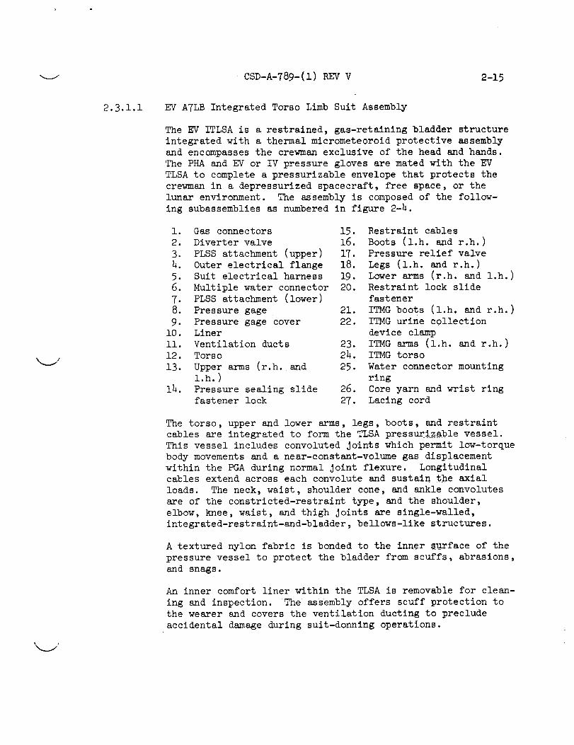
2.3.1.1 EV A7LB Integrated Torso Limb Suit Assembly
The EV ITLSA is a restrained, gas-retaining bladder structureintegrated with a thermal micrometeoroid protective assemblyand encompassesthe crewmanexclusive of the head and hands.The PHAand EV or IV pressure gloves are mated with the EVTLSAto complete a pressurizable envelope that protects thecrewmanin a depressurized spacecraft, free space, or thelunar environment. The assembly is composedof the follow-ing subassemblies as numberedin figure 2-4.
i. Gas connectors2. Diverter valve3. PLSSattachment (upper)4. Outer electrical flange5. Suit electrical harness6. Multiple water connector7. PLSSattachment (lower)8. Pressure gage9. Pressure gage cover
10. Linerll. Ventilation ducts12. Torso13. Upper arms (r.h. and
i.h.)i_. Pressure sealing slide
fastener lock
15. Restraint cables
16. Boots (l.h. and r.h.)
17. Pressure relief valve
18. Legs (1.h. and r.h.)
19. Lower arms (r.h. and 1.h.)
20. Restraint lock slide
fastener
21. ITMG boots (1.h. and r.h.)
22. ITMG urine collection
device clamp
23. ITMG arms (1.h. and r.h.)
24. ITMG torso
25. Water connector mounting
ring
26. Core yarn and wrist ring
27. Lacing cord
The torso, upper and lower arms, legs, boots, and restraint
cables are integrated to form the TLSA pressuri_able vessel.
This vessel includes convoluted Joints which permit low-torque
body movements and a near-constant-volume gas displacement
within the PGA during normal Joint flexure. Longitudinal
cables extend across each convolute and sustain the axial
loads. The neck, waist, shoulder cone, and ankle convolutes
are of the constricted-restraint type, and the shoulder,
elbow, knee, waist, and thigh Joints are single-walled,
integrated-restraint-and-bladder, bellows-like structures.
A textured nylon fabric is bonded to the inner surface of the
pressure vessel to protect the bladder from scuffs, abrasions,
and snags.
An inner comfort liner within the TLSA is removable for clean-
ing and inspection. The assembly offers scuff protection to
the wearer and covers the ventilation ducting to preclude
accidental damage during suit-donning operations.

2-16 CSO-A-789-(1) REV V
26-2'
19
ii
Figure 2-4.- EV A7LB integrated torso limb suit assembly.
i

-__j CSD-A-789-(1) REV V 2-17
Entry into the TLSA is made through restraint-and-pressure
slide fasteners mounted in the waist area of the torso
restraint-and-bladder layers. To preclude accidental opening,
lock assemblies are provided to hold the slide fasteners
closed.
A network of noncrushable ducting laced to the inner TLSA
surface, two sets of inlet and exhaust gas connectors, and a
diverter valve comprise the ventilation distribution system
within the TLSA. The TLSA and the ventilation distribution
system interface with the pressure gloves and helmet to com-
plete the PGA pressurization and ventilation system.
A pressure gage is mounted on the left-arm wrist cone, and a
pressure relief valve is mounted on the rlght-leg thigh cone.
The pressure gage indicates differential pressures of from
2.5 to 6.0 psld, and the pressure relief valve relieves pres-
sures in excess of 5.0 psid.
The suit electrical harness provides signal paths for biomed-
ical instrumentation data and communications transmissions.
The sult-mounted connector permits an electrical and mechan-
ical interface with the spacecraft or PLSS communications
umbilical.
A flange-mounted multiple water connector secured to the torso
provides a mechanical mate between the LCG and PLSS or LM
liquid cooling systems. When the LCG is not worn, a plug is
locked into the connector opening to provide a gas seal.
The ITMG torso, arms, boots, and pressure gage cover afford
flame impingement, thermal, and mlcrometeoroid protection to
the pressurizable portion of the TLSA and to the crewman.
The assemblies employ a multilayered cross section as shown
in table 2-V.
The water connector mounting ring, outer electrical flange,
ITMG urine collection device (UCD) clamp, core yarn, wrist
ring, and lacing cord secure the thermal and micrometeoroid
protective assemblies to the torso limb suit.
Amendment 2
11/5/71

2-18 CSD-A-789-(1) REV V
TABLE 2-V.- EV A7LB ITMG MATERIALS CROSS SECTION
(LISTED FROM THE INSIDE OUT)
kj
Nomenclature Funct ion
_ubber-coated nylon (ripstop)
Nonwoven Dacron
%luminized Mylar film
Nonwoven Dacron
Aluminized Mylar film
Nonwoven Dacron
Aluminized Mylar film
Nonwoven Dacron
Aluminized Mylar film
Nonwoven Dacron
Aluminized Mylar film
Beta marquisette
Gridded a aluminized Kapton film
Beta marquisette
Gridded aluminized Kapton film
Beta marquisette
Teflon-coated yarn Beta cloth
Teflon fabric
Inner liner and micrometeoroid
protection
Thermal spacer layer
Thermal radiation protection
Thermal spacer layer
Thermal radiation protection
Thermal spacer layer
Thermal radiation protection
Thermal spacer layer
Thermal radiation protection
Thermal spacer layer
Thermal radiation protection
Thermal spacer layer
Thermal radiation protection
Thermal spacer layer
Thermal radiation protection
Thermal spacer layer
Flame impingement layer
Abrasion layer
aA 2-inch gridding with Polyemite tape is employed in the arm and
knee areas; 4-inch gridding is provided in all other areas.

CSD-A-789-(1) REV V 2-19
2.3.1.1.1 EV A7LB torso limb suit ass_nbly.- The TLSA is sized to fit
a specific crewman. To further customize the fit of a torso
limb suit, to optimize mobility in the suit, and to provide
maximum comfort, the following adjustments may be made.
a. Neck height e. Arm length
b. Neck angle f. Crotch height
c. Shoulder width g. Crotch and limb angle
d. Elbow convolute height h. Leg length
The torso section and shoulder, wrist, thigh, and lower leg
cones employ a bilayered cross section, an inner gas reten-
tion layer, and an outer structural restraint layer to main-
tain the optimum shape and size of the torso limb suit during
pressurized and depressurized modes of suit operation. The
inner bladder layer is loosely fitted to the restraint layer
and is attached to the restraint layer at strategic points
for support and alinement. The convolutes provided at the
shoulder, elbow, thigh, and knee areas are flexible, single-
walled structures or Joints to satisfy suit mobility require-
ments. Movements in the Joint areas cause little change
in the volume of gas within the PGA, but displace the gas
within the Joint area.
The TLSA boot assembly includes an outer fabric restraint, a
sole and heel assembly, and an inner rubber bladder.
The heel and sole assemblies employ an inner core of aluminum
honeycomb in the heel and arch areas and a stainless steel
truss core in the front sole area. The areas where honeycomb
is used are rigid, and the truss area permits longitudinal
flexibility to accommodate normal foot movements.
Nylon webbings at cable attachment points evenly distribute
restraint loads. Metal eyelets and grommets line and rein-
force the holes provided for cable attachment points.
An abrasion layer secured to the inner bladder wall reduces
wear normally caused by direct contact between the body and
the bladder.
L_
Noncollapsible ducts along the inner wall of the TLSA make up
the ventilation distribution system. Each duct is constructed
of parallel lengths of nylon spacer coils wrapped with a nylon
mesh cloth. The nylon mesh cloth and spacer construction are
dipped in a rubber compound which promotes rigidity of the
cloth and adds a nonslip characteristic between the cloth and
the coil spacers. The assembled unit is then wrapped with

2-2o CSD-A-TSg-(1) V
2.3.1.1.2
2.3.1.2
bladder material to form a noncrushable duct with an airtight
wall. These ducts are secured to the TLSA by a system of
loop-type and lacing cord.
A comfort liner in the interior of the TLSA facilitates donn-
ing and promotes comfort. The leg of the liner assembly is
zipped to the boot liner at the lower leg area. The assembly
is secured to the torso limb suit with hook and pile fastener
tape and snap fasteners at the neck opening, around the wrists,
and along each side of the entry closure. Synthetic elastomer
foam pads over each shoulder and at the biceps area of the
arm promote comfort. Reinforced openings through the liner
provide passages for the suit electrical harness communica-
tions branch, biomedical instrumentation branch, and urine
transfer hose. A communications snap-flap at the front of
the neck opening holds the communications branch in place
to facilitate donning. The front-knee panels and the rear-
elbow panels of the liner are pleated along each side to form
semipockets which afford relief during limb flexation.
Lunar integrated thermal micrometeoroid garment.- The ITMG issized to fit and conforms to the contours of the torso limb
suit. The ITMG may be removed from the torso limb suit for
inspection and maintenance. The multilaminate cross section
of the ITMG prevents thermal damage to, and punctures in, the
torso limb suit, and protects the crewman from the extreme
temperatures and micrometeoroid flux densities normally ex-
pected on the lunar surface and in the free space within the
lunar orbit perimeter. To protect against fire and exposed
surface abrasion, an outer layer of Teflon fabric and an
inner layer of Teflon-coated yarn Beta cloth are provided.
For protection from the thermal environment of free space and
the moon, seven layers of aluminized film are used to reflect
radiant heat and to reduce heat conduction between the alumi-
nized film layers. A low-heat-conducting fabric of nonwoven
Dacron or Beta marquisette is used to separate each layer of
film. An inner layer of ripstop fabric, the thermal protec-
tive layers, and the fire impingement and abrasion layers
provide the mass needed to afford micrometeoroid protection
to the TLSA and crewman.
Pressure Helmet Assembly
The PHA (fig. 2-5) is a transparent bubble which engages with
the torso limb suit and encloses the crewman's head. The
assembly consists of an anodized aluminum neck ring, a vent
pad, a valsalva device, and a transparent polycarbonate shell.

CSD-A-789-(1) REVV 2-21
i !
i i|. iI, II Slip-on helmet, II shield ,
Vent spacer
_ment
mark
channel
Vent pad and
duct assy
Helmetalinement
index
marks
LEVA alinement
mark (on inside of ring)
port
LEVA shell
separation Neck ringalinement
marks Valsalva Feed port coverdevice with Velcro
Figure 2-5.- Pressure helmet assembly and helmet shield.

CSD-A-789-(1) V2-22
The size of the polycarbonate shell permits normal neck
flexion and rotation movements and provides an unobstructed
field of vision in accordance with specified optical
requirements.
The polycarbonate helmet shell is molded and has a ma-
chined bayonet base bonded to the helmet neck ring. The hel-
met neck ring is the male half of the suit neck ring assembly.
Index marks on each neck ring half are used for alinement dur-
ing helmet donning operations, and a rigid airtight Joint is
assured when the two halves are Joined.
A helmet shield is used with the helmet to afford scuff and
abrasion protection during spacecraft tunnel transfers.
The helmet vent pad bonded to the back of the helmet shell
provides shock protection and is used as a helmet ventilation
flow manifold. Vent pad louvers guide a layer of gas along
the inner surface of the helmet to the oronasal area. This
flow of ventilation gas is then distributed through the oro-
nasal area and causes an efficient exhaust of carbon dioxide
from the helmet into the torso area.
The feed port is flange mounted to the pressure helmet and
includes two metal halves, two beaded elastomer gaskets, and
a metal cover. The inner half includes a port and gate valve
that permits the insertion of a water or food probe. The
valve is spring loaded to a closed position and provides an
air-tight seal when the probe is removed. The outer feed port
half provides a gas seal around the opening when the probe is
inserted. A bayonet Juncture holds the feed port cover to
the outer feed port half. Beaded elastomer gaskets fit be-
tween the helmet and each feed port half to ensure a gas seal
at the helmet/feed port mounting surfaces.
A valsalva maneuver device is attached to the pressure helmet
neck ring assembly approximately 37 ° to the left of the sa-
gittal plane. The helmet attaching plate is cemented to theinner circumferential surface of the helmet neck ring at this
location and permits attaching and detaching the device. The
device can be detached fr_n the helmet by depressing the latch
and sliding the device in either direction until free of the
helmet attaching plate.

'__../ CSD-A-789-(1) REV V 2-23
2.3.1.3
2.3.1.4
2.3.1.5
Wri st let s
The wristlets (fig. 2-6) may or may not be selected for use
by the crewman for comfort. The wristlets are cylindrically
shaped and constructed of ribknit cotton material. The wrist-
lets may be attached to the comfort glove to provide the
wrist and lower arm with protection against wrist disconnect
buffeting.
Comfort Gloves
The comfort gloves (fig. 2-6) may be used by the crewman for
comfort. When used, they are worn beneath the EV or IV PGA
pressure gloves to avoid chafe between the skin and the gloves.
The comfort gloves are made of nylon tricot material and are
available in either long or short lengths of standard small,
medium, or large sizes. The long-length gloves are alsoavailable in custom sizes.
IV Pressure Glove Assembly
The pressure glove assembly (fig. 2-6) is a flexible, gas-
retaining device which locks to the torso limb suit by means
of a quick-disconnect coupling (the wrist disconnect). The
bladder assembly is dip molded from a hand cast of the indi-
vidual's hand. The bladder is comprised of an inner restraint
core of nylon tricot covered with a dipped rubber compound.
The dexterity of the bladder is increased by built-in relief
projections over the knuckle areas, and, to facilitate thumb
extension, a gusset is provided in the thumb/forefinger crotch.
A standard convolute section is incorporated in the wrist area
of the bladder to allow omnidirectional movement of the wrist.
The convoluted section is restrained by a nyion restraint fabric
layer and a system of sliding cables secured to a wrist restraint
ring and the glove side-wrist disconnect. The cable restraint
system accepts the axial load across the glove convolute.
The glove side-wrist disconnect is the male portion of the
wrist disconnect assembly and features a sealed bearing which
permits 360 ° glove rotation.
The fingerless glove/outer convolute cover is a restraint
assembly which is cemented onto the bladder at the wrist area
and encloses the entire hand and wrist exclusive of the fin-
gers and thumb. An external palm restraint assembly minimizes
the ballooning effect when pressurized, thereby enhancing grip
control. The convolute covers protect the bladder and con-
volute restraint system.

2-24 CSD-A-789"(1) REVV
Wristlet
EV pressure glove
IV pressure glove Comfo_ glove
Figure 2-6.- Glove assemblies with _ristlets.
V

k._j CSD-A-789-(1) REV V 2-25
k_j
2.3.1.6 EV Pressure Gloves
The EV glove assembly (fig. 2-6) is a protective hand cover-
ing interfaced with the torso limb suit assembly prior to
egress for extravehicular operations. The EV glove consists
of a modified IV pressure glove assembly covered by the EV
glove shell assembly. The assembly covers the entire hand
and has an integral cuff or gauntlet which extends the pro-
tective covering well above the wrist disconnect.
A lunar surface EVA checklist is attached to the EV glove
gauntlet outer shell as a crew/mission requirement. The spe-
cific location, method of attachment, and orientation of the
checklist on the glove gauntlet will be defined by the crew-
man to satisfy specific needs and mission objectives.
The EV glove thermal shell is a multilayered assembly
(table 2-VI) which provides scuff, abrasion, flame impinge-
ment, and thermal protection to the pressure glove and crew-
man. A woven metal (Chromel R) fabric is incorporated over
the hand area for added protection from abrasion. The thumb
and finger shells are made of high-strength silicone rubber
which is reinforced with nylon cloth and provides improved
tactility and strength. A silicone dispersion coating is
applied to the palm, around the thumb, and to the inner side
of each finger for increased gripping.
The outer cover is shaped to the inner pressure glove and
does not appreciably restrict the dexterity of the inner
pressure glove. A flap is sewn onto the back of the glove
shell and provides access to the palm restraint flap. The
flap is opened or closed by engaging or disengaging the hook-
and-pile fastener tape. When the palm restraint flap and
hook-and-pile tapes are disengaged, the glove shell can be
removed by disengaging the cemented interfacing areas near
the fingertips. The materials cross section of the cover
layer of the EV glove assembly is identified in table 2-VI.

2-26 CSD-A-789-(1) REVV
TABLE2-VI .- MATERIALSCROSSSECTIONFOREV THERMALGLOVE
Material Function
Pressure glove
Aluminized Mylar (7 layers)
NonwovenDacron (6 layers)
Teflon-coated Beta yarn(gauntlet only)
Pressure retention
Insulation film
Insulation spacer
Fire resistant shell(gauntlet only)
Teflon cloth(gauntlet only)
Chromel R metal fabric(hand only)
Silicone rubber (fingertips only)
Abrasion resistant(gauntlet only)
Abrasion, fire, heatresistant
Increase friction.
2.3.1.7 Data List Pocket Assembly
The data list pocket assembly (fig. 2-7) is a strap-on assem-bly which is normally wrapped around the lower left or rightleg of the ITMG. The pocket is attached to the leg by twostraps held in place by belt loops. The pocket opens andcloses by meansof an overhanging flap secured by strips ofh0ok-and-pile fastener tape. The data list pocket maybeprovided as an EV contingency sample pocket. The walls ofthe pocket include removable stiffeners which hold the pocketopen to reduce interferences while inserting or removingarticles.
The pocket maybe secured to the left thigh in an upright orupside downattitude to attain maximumaccessibility to thepocket. Hook-and-pile fastener tape is employed to hold thepocket flap in the open position whenthe pocket is uprightand secured to the thigh.

_ CSD-A-789-(1) REVV 2-27
Straps i I
/ Checklist pocket
/ Scissors pocket
f Stiffener assy
. ..... _, __Stiffener_ insert
• . _;
Figure 2-7.- Detachable pocket assemblies.

2-28 CSD-A-789-(1)REV V
2.3.1.8
2.3.1.9
2.3.1.10
2.3.1.11
Checklist Pocket Assembly
The checklist pocket assembly (fig. 2-7) is a strap-on assem-
bly consisting of a checklist pocket and belt assemblies.
The entire assembly straps onto the lower right or left leg
of the ITMG. Belt loops on the legs of the ITMG hold the
pocket in position.
Scissors Pocket Assembly
The scissors pocket (fig. 2-7) may be attached to the straps
of the checklist pocket assembly or secured to the ITMG as a
crew/mission requirement. The exact location on the ITMG
shell is defined by the crewman and specific mission objectives.
Biomedical Harness
The biomedical harness (fig. 2-8) is an electrical cable as-
sembly which interconnects the signal conditioners and dc-to-
dc converter within the biomedical belt and interfaces with
the suit electrical harness.
Lunar Boot s
The lunar boot (fig. 2-9) is a thermal and abrasion protective
device worn over the ITMG and PGA boot assemblies during lunar
extravehicular operations. It permits free articulation of
the foot and does not restrict mobility of the PGA boot.
Donning is accomplished by inserting the PGA boot into the
enlarged upper portion of the lunar boot. A donning strap
assembly (located at top rear) facilitates positioning of the
PGA boot within the lunar boot. The surplus material at the
upper front edge folds over to overlap the tongue area and is
held closed by engaging a snap fastener and retaining strap
attached to each fold. Further security is provided by a
strap assembly which extends from each side of the heel and
crosses the instep. The strap incorporates a latching mech-
anism which is easily actuated even while wearing EV gloves.
Table 2-VII defines the material cross section of the lunar
boot assembly.

CSD-A-789-(1) REVV 2-29
L
Biomedical sensors
(5 places)
Biomedical belt
Signal conditionersBiomedical harness
Figure 2-8.- Biomedical harness and sensors.

2-30 CSD-A-789-(1) REV V
Donning strap Snap fastener
Shell assemblyp assembly
J
I
Liner and insulation assembly- "_Latch
Left boot
Retaining strap assembly
ole assembly
Right boot
Figure 2-9.- Lunar boots.
17

-_ CSD-A-789-(1) REV V 2-31
TABLE 2-Vll.- MATERIALS CROSS SECTION FOR LUNAR BOOT
% ;
Material Function
Teflon-coated Beta cloth
Aluminized Mylar
Nomex felt
Aluminized Mylar (9 layers)
Nonwoven Dacron (9 layers)
Beta marquisette Kapton
laminate (2 layers )
Teflon-coated Beta cloth
High-strength silicone rubber
Chromel R metal fabric
Boot liner
Insulation film
Thermal boot pad
Insulation film
Insulation spacer
Outer insulation
Fire resistant shell
Lunar boot sole
Abrasion, fire, heat resistant
2.3.1.12 Neck Dam
The neck dam assembly (fig. 2-10) is a sealing device to pre-
vent water seepage into the TLSA through the neck opening
during suited operations in the water. The assembly consists
of a neck dam seal constructed of rubber, a neck dam ring
assembly made of flexible metal, and a storage lanyard. The
neck dam assembly is conically shaped with a sized opening
for the head and neck. The neck dam is donned after reentry
and Just prior to spacecraft egress operations. The size of
the neck dam is determined by the circumference of the head
and neck opening in the neck dam seal. The size can be identi-
fied by the part number suffix (-lh00, neck size lh; -lh50,
neck size i_-i/2; etc.), and it is available in sizes 13-1/2to 16-1/2.
2.3.2 CMP ATLB Pressure Garment Assembly
The CMP A7LB PGA functions as a part of the spacecraft envi-
ronmental control system or the EMU. The PGA contains a
habitable environment and protects the astronaut from exposure

2-32
."21J
._,2_
m, TT,r) m, T'T
N_ L'M N
I _ I -- I
__ ___, __
Amendment 2
11/5/71
CSD-A-T89-(1) REV V
+_
/
o
O
Ii
o
I

CSD-A-789-(1) REV V 2-33
L /
L j
2.3.2.1
to thermal and micrometeoroid conditions during EV activities
in the free space within the lunar orbit perimeter. The com-
ponents of the PGA include:
a. CMP ATLB ITLSA
b. PHA
c. Wristlets
d. Comfort gloves
e. IV pressure gloves
f. EV gloves
g. Data list pocket
h. Checklist pocket
i. Scissors pocket
J. Biomedical harness
k, Neck dam
CMP A7LB Integrated Torso Limb Suit Assembly
The CMP ITLSA is a restrained, gas-retaining bladder structure
integrated with a thermal micrometeoroid protective assembly.
The CMP ITLSA encompasses the crewman exclusive of the head
and hands. The PHA and EV or IV pressure gloves are mated
with the CMP TLSA to complete a PGA for protecting the crew-
man in a depressurized spacecraft or free space environment.
The ITLSA consists of the following subassemblies as numbered
in figure 2-11.
i. Torso 13.
2. Pressure gage 14.
3. Torso adjusting strap
4. Restraint cables 15.
5. Pressure sealing slidefastener 16.
6. Boots (r.h. and 1.h.)
7. Legs (r.h. and l.h.) 17.
8. Pressure relief valve
9. Gas connectors with 18.
diverter valves 19.
i0. Arm assembly 20.
ll. Suit electrical harness
12. Upper arms (r.h. and 21.
l.h.)
22.
Liner
Core yarn, wrist ring and
lacing cord
Cover layer assembly boots
(r.h. and l.h.)
UCD and medical injection
access flap
Cover layer assembly arms(r.h. and 1.h.)
Pressure gage cover
Cover layer assembly torso
Ventilation ducts (not
shown)
Outer electrical flange
(not shown)
ITMG UCD clamp (not shown)
The torso, upper and lower arms, legs, boots, and restraint
cables are integrated to form the CMP TLSA pressurizable vessel.
This vessel includes convoluted Joints for low-torque body
movements and a near-constant volume displacement during
normal Joint movements. Longitudinal cables extend across
each convolute and sustain the axial loads. The shoulder
cone and ankle convolutes are of the constricted-restraint
type; and the shoulder, elbow, knee, waist, and thigh Joints
are single-walled, integrated restraint and bladder, bellows-
like structures.

2-34 CSD-A-789-(_I) REV Y
V
13
12
II
i
3
4\
\ 5
19
17
16
• I
Figure 2-11.- CMP A7LB integrated torso limb suit.
k.#
I

\ /
-.__j CSD-A-789-(1) REV V 2-35
An inner comfort liner within the TLSA is removable for clean-
ing and inspection. The assembly offers scuff protection to
the wearer and covers the ventilation ducting to preclude
accidental damage during suit-donning operations.
Entry into the TLSA is made through an integrated restraint
and pressure slide fastene r assembly mounted vertically along
the spinal column and through the crotch area. To preclude
accidental opening, a lock assembly for the pressure sealing
slide fastener holds i% in the closed position.
A network of noncrushable ducting secured to the inner TLSA
surface, two sets of inlet and exhaust gas connectors, and a
diverter valve for each inlet connector comprise the ventila-
tion distribution system within the TLSA. The TLSA and a
ventilation distribution system interface with the pressure
gloves and helmet to qomplete the PGA pressurization and
ventilation system. A pressure gage is mounted on the left-
arm wrist cone, and a pressure relief valve is mounted on the
left arm. The pressure gage indicates differencial pressures
of from 2.5 to 6.0 psid, and the pressure relief valve relieves
pressures in excess of 5.0 psid.
The suit electrical harness provides a signal path for bio-
medical instrumentation data and communications transmissions.
The suit-mounted connector permits an electrical and mechani-
cal interface with the spacecraft or PLSS communications
umbilical.
The cover layer assembly (CLA) torso, arms, boots, and pres-
sure gage cover afford flame impingement, thermal, and micro-
meteoroid protection to the pressurizable portion of the TLSA
and to the crewman. The assemblies employ a multilayered
cross section as shown in table 2-VIII.
The outer electrical flange, ITMG UCD clamp, core yarn, wrist
ring, and lacing cord secure the thermal and micrometeoroid
protective assemblies to the torso limb suit.
Amendment 2
Ii/5/71

2-36 CSD-A-789-(1) REV V
TABLE 2-VIII.- C%fPA7LB CLA MATERIALS CROSS SECTION
(LISTED FROM THE INSIDE OUT)
Nomen clature Funct ion
Rubber-coated nylon (ripstop)
Aluminized Mylar film
Nonwoven Dacron
Aluminized Mylar film
Nonwoven Dacron
Aluminized Mylar film
Nonwoven Dacron
Aluminized Mylar film
Nonwoven Dacron
Aluminized Mylar film
Aluminized Kapton film/
Beta marquisette, laminate
Aluminized Kapton film/Beta
marquisette laminate
Teflon-coated yarn Beta cloth
Teflon fabric
Inner liner
Thermal radiation protection
Thermal spacer layer
Thermal radiation protection
Thermal spacer layer
Thermal radiation protection
Thermal spacer layer
Thermal radiation protection
Thermal spacer layer
Thermal radiation protection
Fire and thermal radiation
protection
Fire and thermal radiation
protection
Fire protection
Abrasion protection
2.3.2.1.1 CMP A7LB torso limb suit assembly.- The CMP TLSA is similarto the EV TLSA described in paragraph 2.3.1.1.1 except for
the following details.
a.The ventilation distribution system ducts are secured to
the TLSA in the EV configuration by a system of loops
and lacing cord and, in the CMP configuration, by hook
and pile fastener tape and bonding strips.

k._j CSD-A-789-(1) REV V 2-37
2.3.2.1.2
2.3.2.2
2.3.2.3
2.3.2.4
2.3.2.5
2.3.2.6
2.3.2.7
2.3.2.8
2.3.2.9
2.3.2.10
b. The semipockets at the knees of the comfort liner are
formed by front panel pleats in the EV configuration and
by rear panel pleats in the CMP configuration.
CMP cover layer assembly.- The CLA is identical to the lunarITMG described in table 2-VIII.
Pressure Helmet Assembly
The CMP PHA is identical to the EV PHA described in para-
graph 2.3.1.2 and figure 2-5.
Wristlets
The CMP wristlets are identical to the EV wristlets described
in paragraph 2.3.1.3 and figure 2-6.
Comfort Gloves
The CMP comfort gloves are identical to the EV comfort gloves
described in paragraph 2.3.1.4 and figure 2-6.
IV Pressure Gloves
The CMP pressure glove assembly is identical in all respects
to the EV pressure glove assembly described in paragraph 2.3.1.5and figure 2-6.
EV Gloves
Refer to paragraph 2.3.1.6 and figure 2-6.
Data List Pocket
Refer to paragraph 2.3.1.7 and figure 2-7.
Checklist Pocket
Refer to paragraph 2.3.1.8 and figure 2-7.
Scissors Pocket
Refer to paragraph 2.3.1.9 and figure 2-7.
Biomedical Harness
Refer to paragraph 2.3.1.10 and figure 2-8.

_m
2-38
2.3.2.11
CSD-L79 q-(1) V
Neck Dam
Refer to paragraph_2._.l.12 and figure 2-10.
2.3.3
2.3.3.1
2.3.3.2
2.3.3.3
Interface Components
This paragraph contai_ descriptions of the components which
interface the torso I_ suit with other components of the
EMU or with the space_ft, and those which are provided as
accessories to the suit. The interface and accessory com-
ponents are as follows_.
a. PLSS attachments _
b. Tether attachment.s_
c. Helmet attaching ring
d. Wrist disconnects _
e. Gas connectorsl
f. Diverter valve:
g. Multiple wate_ co]_nector
h. Urine transfer connector
i. Medical injection patch
J. Zipper lock assemblies
k. Pressure relief valve
I. Biomedical belt
m. Biomedical harness
n. Suit electrical harness
PLSS Attachments
Two attachment bracke+_s (fig. 2-12) on the EV ATLB PGA anchor
the shoulder and _ais_PLSS support straps in place. The
upper bracket is fixe_o the torso sternum area. The lower
PLSS attachment is_ fi-_ed over the ITMG and snapped to the
front torso crotc_ cable "D" rings located in the abdominal
area.
Tether Attachment --
Tether attachments (fi6. 2-13) are available at the left and
right sides of the EV_GA. The attachment interfaces with
and becomes a par_ of_the IM tether system. The LM tether
system with the PGA _her attachments provide an artificial
gravity to assist_th_ewman in maintaining stability with-
in the LM.
Helmet Attaching Ring_sembly
The helmet is att_ch_ to the TLSA by a self-latching, self-
sealing, quick-discor_n_ect coupling (fig. 2-14). The TLSA
side of the coupling consists of a neckring housing, eight
latch assemblies,[a _ating locking ring, and a pushbutton
lock subassembly On t_e locking ring. Index marks and
Amendment 2
1l/5/7l
4

k._./ CSD-A-789-(1) REV V 2-39
O
Upper PL SS attachment
Cover
D-ring connector
Bracket
Spring Ring
Lower PL SS attachment
Figure 2-12.-PLSS attachments.

m
2-40 CSD-A-789-(1) REV V _J
Tether attachment
\Waist pulley assembly
Figure 2-13.- Lunar module tether attachments (A7LB EV).
k_J
ii

CSD-A-789-(1) REV V 2-41
Lock button
___ ._-.Lock subassembly
_- Lock stop _Front
CMP A7LB
-- Index marks
Front
" Lock subassembly
Lock stop
EV A7 LB
• Figure 2-1h.- Helmet attaching neck ring.

2-42 CSD-A-78_-(_l) REY Y
4
"" ......II
fHelmet alinement for donning
"\
'2
Helmet/suit neck ring engaged
A7LB CMPNeck ring locked
A7 LB EV
Figure 2-14.- Concluded.
rll

CSD-A-789-(1) REV V 2-43
2.3.3.4
2.3.3.5
printed labels on the helmet neckring identify the ENGAGE
and LOCKED positions and facilitate alinement and engagement
with the TLSA neckring. Positive locking of the helmet-to-
TLSA coupling is ensured by a TLSA-mounted locking ring which
is rotated by hand to the engaged, locked, or release posi-
tions. A pushbutton lock on the TLSA locking ring permits
rotation of the locking ring to the LOCKED position and pre-
vents accidental unlocking. The helmet is donned with the
TLSA locking ring in the ENGAGE position by alining and
pressing the helmet into place until the latches catch. The
helmet is then locked into place by pressing the pushbutton
on the TLSA locking ring, sliding the pushbutton lock out-
ward, and rotating the TLSA locking ring to the LOCKED posi-
tion. The helmet is removed by pressing the pushbutton on
the TLSA locking ring, sliding the pushbutton lock outward,
and rotating the TLSA locking ring past the ENGAGE position
to the release position. When the TLSA locking ring is re-
leased at the helmet release position, it returns automati-
cally to the ENGAGE position.
Wrist Disconnects
The PGA wrist disconnect (fig. 2-15) coupling includes a suit
(female) half and a glove (male) half. The female coupling
incorporates a manually actuated lock and unlock mechanism,
which has three positions, ENGAGE, LOCK, and UNLOCK. The
male half incorporates a sealed bearing which permits 360 °
glove rotation. The male half of the disconnect is engaged
to the female half by alining the glove-half coupling and
placing it into the suit-half coupling with the locking ring
in the ENGAGE position, then rotating the locking ring to
the LOCK position. The glove-half coupling is disengaged or
removed from the suit-half coupling bydepresslng the lock-
lock button with the index finger, and with the thumb and
second finger, pulling the two locking tabs from the LOCK
position and rotating the locking ring to the open (UNLOCK)
position.
Gas Connectors
Two inlet and two outlet gas connectors (fig. 2-16) permit
the exchange of vent system umbilicals without interrupting
the flow of gases to and from the suit. All inlet gas con-
nectors and mating umbilical connectors are anodized blue,
and all outlet connectors and mating umbilical connectors
are anodized red to preclude reversed connections.
Amendment 2
11/5/71

2-44 CSD-A-789-(1) REV V
Lock tab_ ....
Index marks _ _../L__lv. ocKing
ring
Lock button-.../,,_ / _1_1 - Seal
//f///// / /_Ll[_ ) , Inner race
Lock tab _
Vent
Latch (8) _II_i[_l / _'_i/_ passage
Wrist disconnect(suit side) _ Outer race
Wrist disconnect
(glove side)
Figure 2-15.- Wrist disconnects.
"k_J

CSO-A-T89-(1) REV V 2-45
Inner housing
Outer housing _
• Seal_,Plunger release "_
Locking ring
/_Cap
Vent hole
Spacer\
Outer housing --'
Diverter valve CMP A7LB
Inner housing
TLSA J'"
Flange
Water block
i
Spring
Cage
Gas connecterEV A7 LB
Blade housing
Cage
IHub subassembly
Figure 2-16.- Gas
TLSA
I Outerflangel
)acer
connectors and
Diverter valveEV A7 LB
diverter valve.

2-46 CSD-A-789-(1) REV V
2.3.3.6
The connectors (inlet and outlet) are ball-lock devices and
have automatic locking and manual unlocking features. A
spring-loaded-closed, mechanically-opened check valve or
water block is an integral part of each gas connector. When
the umbilicals are disconnected, the check valve or water
block prevents pressure loss through the connector. Should
the PGA become submerged, the check valve will also prevent
water flow through the valves. The check valves are held
open by the gas umbilicals when connected. Gas connector
caps block the unused connector ports to prevent inadvertent
opening of the valve or water block when the umbilicals are not
installed. A vent hole through the cap prevents a pressure
buildup under the cap when it is inserted _nto the connector.
The ventilation umbilicals are engaged by inserting the um-
bilical connectors into the PGA gas connector openings and
pressing them firmly into place (the engaging force does not
exceed 20 pounds). The umbilicals must be inserted straight
into the gas connectors to prevent side loading and damage to
the "0" ring seals. The redundant lock is engaged by sliding
the tab toward the connector base and into the recess of the
upper housing.
The umbilicals are disengaged by releasing the redundant lock
and then pulling outward with the forefinger until
the tab is clear of the recess in the upper housing' The um-
bilical may then be released by pulling the locking tabs out-
ward with the thumb and forefinger, thus disengaging them
and enabling the locking ring to be rotated to the OPEN posi-
tion. The gas connector locking ring will automatically lock
in the open position to permit immediate or subsequent reen-
gagement of the umbilical.
Diverter Valve
A DV (fig. 2-16) to direct the flow of air into the suit is
mounted in the central chest area of the EV PGA near the gas
connectors. The DV has two functional positions, CLOSE and
OPEN. In the CLOSE position, all inlet gas flow is directed
to the helmet by the blade on the DV. In the OPEN position,
the blade divides the inlet gas flow and diverts a part of
it through the torso duct and to the helmet.
A ridged projection on the DV control knob identifies the
position of the valve blade. When the ridged projection is
vertical (CLOSE position), the blade blocks the passage to
the torso duct; when it is horizontal (OPEN position), the
blade opens the torso duct passage. k_W
z;,

-'_J CSD-_-789-(I) REV V 2-47
k_/
2.3.3.7
2.3.3.8
The DV may be rotated 360 ° in either direction, and spring-
loaded, positive (locking) detents are provided at 90 ° in-
tervals. The valve is operated by pulling out the control
knob and rotating it in either direction to the desired posi-
tion until the locking detent engages.
Multiple Water Connector
The multiple water connector (MWC) receptacle (fig. 2-17)
includes a double-ball-lock system to engage an LCG dual-
passage connector to the inner ball-lock mechanism and a PLSS
dual-passage connector to the outer ball-lock mechanism. A
plug inserted into the receptacle and locked in place replaces
the LCG connector when the LCG is not worn. The plug extends
through the receptacle to aline it with the outer surface ofthe suit.
The inner mechanism is a manually actuated locking and unlock-
ing device. With the locking ring in the OPEN position, the
LCG connector is alined with the receptacle port, positioned
with the thumb and forefinger, and rotated to the LOCKED
position.
The LCG connector is disengaged by pulling out the two locking
tabs with the thumb and forefinger and rotating the locking
ring to the OPEN position. The LCG connector may then be
extracted from the receptacle.
To engage the PLSS connector, the connector must be alined
with the port of the receptacle and placed into the recepta-
cle (engaging force should not exceed 20 pounds). The lock-
ing mechanism will automatically lock the connector in place.
The connector position may be engaged in 180 ° increments to
facilitate convenient connection in the LM.
The PLSS connector may be disengaged by pulling the two lock-
ing tabs out and rotating the locking ring to the OPEN posi-
tion. The locking mechanism will then remain in the OPEN
position, ready for immediate or subsequent reengagement.
Urine Transfer Connector
The urine transfer connector assembly (fig. 2-18) consists of
a PGA-mounted, ball-lock connector and a sized length of in-
terconnecting hose. The connector is flange mounted to the
rlght-leg thigh cone of the PGA where it mates with the urine
transfer umbilical of the spacecraft management system. The
hose assembly is mounted to the connector on the inside of

CSD-A-789-(1) REVV2-4.8
.°
Multiple water connectorring
Locking ring
Alinement mark
ITMG
Housing sub-
assembly
Multiple water connectormounting ring
Roll pin
O-ring
Figure 2-17.- Multiple water connector.
Amendment 2
11/5/71
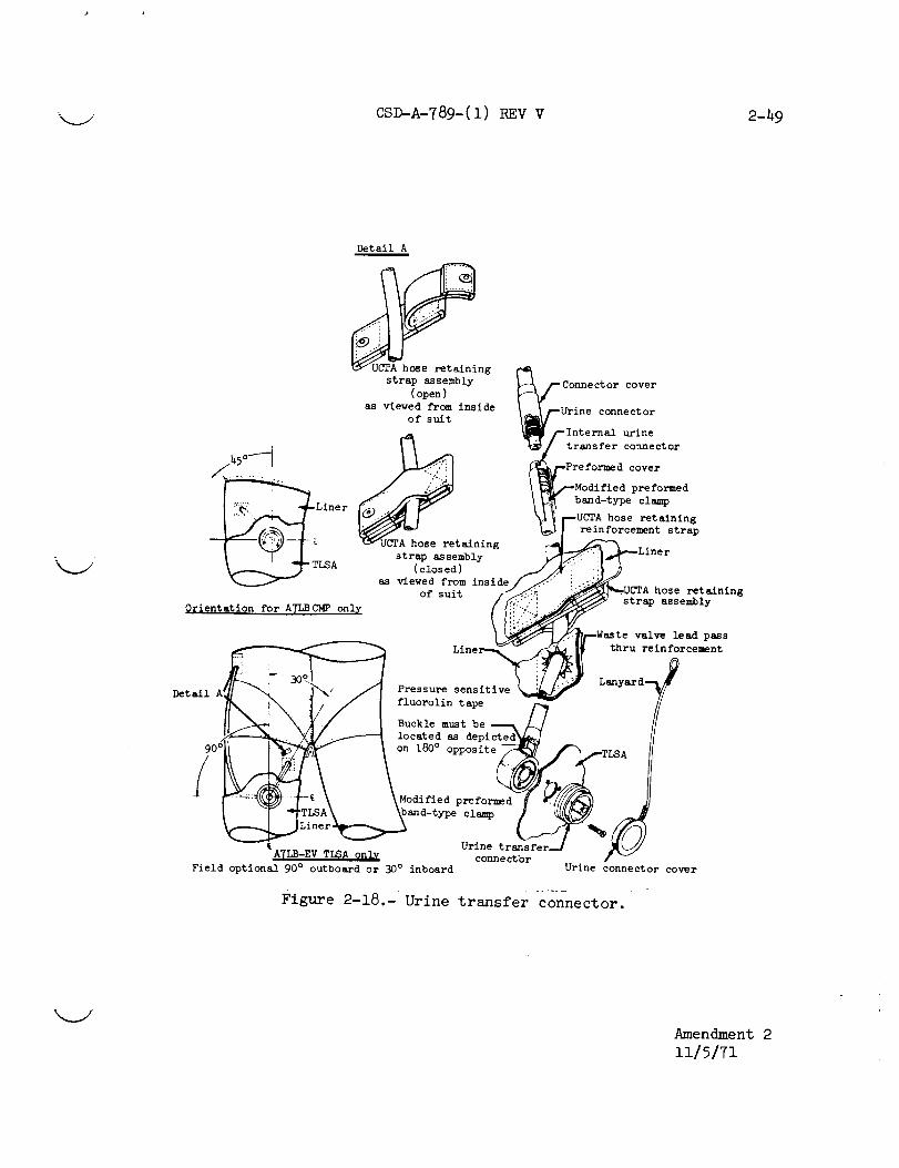
_. CSD-A-789-(1) REV V 2-49
Detail A
strap assembly
(open )
as viewed from inside
of suit
Conne ctor cover
Urine connector
{_tlr_:__inector
....... :: Modified preformed
Liner band-type clamp
i p-UCTA hose retaining
._.I re/_rcement st rap
strap aSsembly
___ TLSA (closed )viewed fromas insld_ i_UCTA hose retaining
__/--Waste valve lead pass
Line__ I thru re
Lanyard
-'_ _/ thru reinfircement
Detail A Pressure sensitive
fluorolin tape /-_
Buckle must be
,',x_----_ X_/,_--_ located as depicted_]
q--_-_"_ l "-_- \ \Modified preformed U IT/////_---_)
_LTiI_neAr_and-type UrinCl_tr%anSfer____
ATLB- ,EV TLSA only connectbr
Field optional 90 ° outboard or 30° inboard Urine connector cover
Figure 2-18.- Urine transfer connector.
-%__./i
Amendment 2
11/5/71

2-50 CSD-A-789--(1) V kj
2.3.3.9
2.3.3.10
the PGA, and it extends to a male adapter which mates with
the UCTA connector. The assembly transfers urine from the
UCTA to the spacecraft waste management system. A preformedrubber connector cover is fitted over the mated UCTA/TLSA
urine transfer hose cor_nector to improve comfort and to pre-
clude possible abrasio_ to the TLSA bladder.
Biomedical Injection P_tch
A circular biomedical fnJection patch (fig. 2-19) is sewn to
the left-thigh cone of the PGA. The patch is made from a
silicone rubber disk which is self-sealing to permit a crew-
man to inject a hypodermic in a vacuum environment without
Jeopardizing the pressure integrity of the PGA. The patch
is placed at approximately the midpoint of the PGA thigh cone
and is identified by a red zigzag stitch line around the
perimeter.
Zipper Lock Assemblies
A separate zipper lock'assembly (fig. 2-20) is provided for
the PGA restraint and pressure-sealing slide fasteners (zip-
pers) on the EV A7LB PGA, and a single lock is provided for
the pressure-sealing s_ide fastener on the CMP A7LB PGA.
The lock assemblies ar4 of different configurations. The
locks engage and hold t_e zipper sliders when they are at the
fully closed positions jon the zipper. The zipper lock assem-
blies include additiona_l or redundant lock features to pre-
vent inadvertent release of the lock.
The EV A7LB restraint zipper lock assembly (fig. 2-20) is
mounted on the slider of the horizontal restraint zipper and
engages the slider on the vertical restraint zipper slider
when both zippers are in the fully closed positions. The
lock assembly is operated by fully engaging the slider of
the vertical restraint zipper into the lock and squeezing
the red striker until fhe lock-lock tab snaps into the lock
position. To release the lock, the lock-lock tab is pulled
out, and the zipper lock strike is moved out free of the ver-
tical zipper slide.
The EV A7LB pressure zipper lock assembly (fig. 2-20) for
the pressure sealing zfpper is mounted on the CLOSE zipper
stop. When the zipper is fully closed, the slider depresses
the safety plunger whic_n permits the lock to be actuated.
The lock is actuated by pressing inward on the safety shaft
while simultaneously turning it until the spring retaining
pin is moved fully int6 the detent slot. To disengage the
%.#
!

k__./ CSD-A-789-(1) REV V2-51
I
Medical injection patch
Figure 2-19.- Medical injection patch.

CSD-A-789-(1) REV V2-52
.,'4
u'lffl
0r-t
%
!
o
!04
.el
Amendment 2
ii15171

_k___ 2-52 CSD-A-789-(.I) REVV
EV A7LB pressure zipper
lock assembly
EV A7 LB restraint zipper
lock assembly
CMP A7LB slide fastener
lock assembly
Figure 2-20.- Zipper lock assemblies.
Iiii

___/ CSD-A-789-(i) REV V 2-53
lock, the locking shaft is depressed and the safety arm is
rotated out and away from the zipper allowing the locking
shaft to disengage the zipper strike.
The CMP A7LB pressure-sealing slide fastener lock assembly
(fig. 2-20) holds the slider of the pressure-sealing closure
to prevent accidental opening. The lock assembly may be
placed in two positions, LOCK and UNLOCK. The LOCK position
is achieved by pushing the lock slider inboard to the stop
using the thumb and forefinger. The red slider should not
protrude beyond the body of the assembly when the slider is
in the LOCK position. An OPEN position is achieved by push-
ing the lock assembly release button outboard of the stop
using Just the thumb. To engage the lock to the pressure-
sealing closure slider, the lock assembly is firmly pulled
over the slider and then the assembly is locked. The slide
fastener closure is released by unlocking the lock assembly
and lifting the lock assembly away from the pressure-sealing
closure slider. A detent assembly holds the lock assembly
slider in the LOCK and UNLOCK positions'
2.3.3.11 Pressure Relief Valve
The pressure relief valve (fig. 2-21) relieves suit pressures
in excess of 5.0 psid. Relief cracking limits are 5.0 to 5.75
psid. The valve will reseat as suit pressure reduces to
4.6 psid and shall not leak more than 4.0 scc per minute when
closed at 4.6 psid. The valve accommodates a relief flow of
12.2 lb/hr minimum at 5.85 psia in the event of a faulted-
open primary oxygen pressure regulation in the PLSS.
The pressure relief valve may be blocked to preclude the re-
lief of suit pressure or to stop leakage through the valve.
A cap fitted over the valve and locked in place by a cam lock
system blocks the exhaust ports to prevent pressure relief
through the valve.
Amendment 2
11/5/71

2-54 CSD-A-789-(1) REV V
'Screw (6)
\
Screw (6) '\%
\k
\%
\
\Pressure rel ief_---_ '\
valve cap__,
Pressurerelief valve
Figure 2-21.- Pressure relief valve.
Amendment 2
i1/5/71

CSD-A-789-(1) REV V 2-55
2.3.3.12
2.3.3.13
2.3.3.14
Biomedical Belt
The biomedical belt (fig. 2-22) supports the signal condi-
tioners and power converter as a part of the biomedical in-
strumentation system. The power converter is located in the
right-hand pocket (as worn), the ECG signal conditioner in
the center pocket, and the impedance pneumogram (ZPN) signal
conditioner in the left-hand pocket. The connector ends of
these units are colored red, blue, and yellow, respectively.
When installing or reinstalling the units, the above order
is maintained to assure that proper signal path connections
are made. When the belt is transferred between the LCG and
CWG, the color-coded electrode harnesses are disconnected at
the units, and the units are retained in the belt. The bio-
medical harness need not be disconnected from thebelt. The
electrodes are not removed to change garments.
Biomedical Harness
The biomedical harness (fig. 2-22) is a four-branch assembly
that interfaces with the two biomedical instrumentation signal
conditioners (ECG and ZPN), the dc-dc power converter, and
the main branch which mates with the suit electrical harness.
The wires are covered with a sheath of Teflon fabric anchored
to each connector by nylon wrapping cord. The harness is
held in place by the biomedical belt and, through its mechan-
ical connectors, with the dc-dc converter and the signal
conditioner.
Suit Electrical Harness
The suit electrical harness (fig. 2-22) has a central 61-pin
connector from which two branches extend. One branch con-
nects to the communications cap or carrier, while the second,
shorter branch connects to the biomedical harness. The com-
munications branch has a 21-pin connector, and the biomedical
instrumentation branch has a 9-pin connector. A groove ma-
chined into the mounting face of the central 61-pin connector
uses an 0 ring to provide a seal when the electrical harness
is mounted to the TLSA. Each branch is covered with a Teflon
fabric sheath. The Teflon fabric sheaths are attached to
each connector with wrapping cord and an adhesive. The cen-
tral 61-pin connector receives the ball/lock engagement mech-
anism of the communications and biomedical instrumentation
umbilical of the spacecraft or the PLSS. The 9- and 21-pin
connectors employ a dual-pawl or latch-engaglng mechanism.

CMP A7LB EV A7LB
Figure 2-22.- Biomedical and suit electrical harness
and biomedical belt.

CSD-A-789-(1) REVV 2-57
J
Wm
n
m gin Moq _ll oWL)
• II,*' iiW4 _gl BTP, lilO
• _ lu411L. ITIglg
• ilia FLTIR _ -
_'_N FILTi[R
IL
41IT I
Electrical schematic
1
_ I
I /1
--i
D
Figure 2-22.- Concluded.
? J-- PHONE !
?
|TO OC -DC CONVIRTEll
i
4
6
m
4
I
I
It
m
6
4
I
|
6kEPT
[ AlIPHOlll
TO XPN
TO I_M
\ /
Amendment 2
ii/5171

2-58 cso-A- 8 (11 v
2.3.4 Controls and Displays
The PGA controls and displays control and monitor the inter-
nal pressure and ventilation. The pressure controls provide
automatic and manual control of the suit pressure. The ven-
tilation control is manually operated. The controls and dis-
plays consist of an automatic pressure relief valve mounted
on the right-thigh cone, manual purge and diverter valves
mounted on the chest area, and a pressure indicating gage on
the left-wrist cone. The pressure relief and diverter valves
are described in paragraphs 2.3.3.ii or 3. i, the pressure
gage in paragraphs 2.3.3.6 and 3.1, and the purge valve in
paragraphs 3.1 and 2.3.5.10.
2.3.5.2
Pressure Garment Accessories
Fecal Containment Subsystem
The FCS (fig. 2-23) consists of a pair of elasticized under-
wear shorts with an absorbent liner material added in the
buttocks area and with an opening for the genitals in the
front. Foam rubber is placed around the leg opening, under
the scrotal area, and at the spinal furrow. This system is
worn under the CWG or LCG to permit emergency defecation dur-
ing the periods when the PGA is pressurized. The FCS collects
and prevents the escape of fecal matter into the pressure
garment. The moisture contained in the fecal matter is ab-
sorbed by the FCS liner and is evaporated from the liner into
the suit atmosphere where it is expelled through the PGA ven-
tilation system. The system has a capacity of approximately
i000 cc of solids.
Urine Collection and Transfer Assembly
The UCTA (fig. 2-23) collects and provides intermediate stor-
age of liquid waste during launch, EVA, or emergency modes
when the spacecraft waste management system cannot be used.
The UCTA will accept fluids at rates to 30 cc/sec with a max-
imum stored volume of 950 cc. No manual adjustment or opera-
tion by the crewman is required for operation of the UCTA.
A flapper check valve prevents reverse flow from the collec-
tion bag. When feasible, the stored urine can be transferred
k.J

____j. CSD-A-789-(1 ) REV V 2-59
\
F
Mating illustratedin figure 2 18 J
UCTA
Figure 2-23.- Fecal containment subsystem and urine collection
and transfer assembly.

2-60 CSg-A-789-(1)REV V
2.3.5.3
2.3.5.4
through the suit wall by hose to the CM or IM during pres-
surized or depressurized cabin operation.
The UCTA is worn over or under the CWG or the LCG and is con-
nected by hose to the urine transfer connector on the PGA.
The urine transfer connector is a qulck-dlsconnect fitting
used to transfer urine frcm the UCTA to the spacecraft waste
management system. A UCTA transfer adapter is provided on
board the CM for use by the crewman to dump the liquid waste
after the PGA has been doffed.
Constant Wear Garment
The CWG (fig. 2-24) is a one-piece cotton undergarment which
is worn next to the skin and encompasses the entire body ex-
clusive of the head and hands. It is worn during IV CM op-
erations for general comfort, to absorb perspiration, and to
hold the biomedical instrumentation system. It absorbs ex-
cessive body moisture and prevents the crewman's skin from
becoming chafed by the pressure garment. The CWG is donned
and doffed through the front opening which is kept closed by
five buttons. The feet are covered by socks sewn to the legsof the CWG.
Waste management is accommodated without removing the CWG by
a fly opening in the front and a buttock port in the rear.
Snap fasteners attach the biomedical instrumentation belt.
Although the CWG may be worn under either the CMP or EV pres-
sure garments, it is normally used during IV phases of the
mission or during EVA work from the CM.
CWG Electrical Harness
The CWG electrical harness (fig. 2-24) is used with the CWG
or inflight coverall garment and provides a mechanical and
electrical interface with the communications carrier, biomed-
ical harness assembly, and the spacecraft communications um-
bilical. It replaces the suit electrical harness when thePGA is doffed and the CWG is worn.
The CWG electrical harness consists of a central 61-pin con-
nector from which two branches extend. One branch conducts
communications signals while the second, shorter branch con-
nects to the biomedical harness. The communications branch
includes a 21-pin connector which interfaces with the com-
munications carrier or lightweight headset. The biomedical
instrumentation branch has a 9-pln connector which interfaces

CSD-A-789-(1) REV V 2-61
CWG electrical harness assembly
CWG
Figure 2-24.- Constant wear garment and electrical harness.

2.B.5.5
with the biomedical harness. The 61-pin connector protrudes
through the inflight coverall garment at the upper chest area
to engage with the electrical umbilical. An aluminum washer
spacer positions the 61-pin connector housing and ensures
proper depth of engagement when the ball-lock mechanism of
the electrical umbilical is Inter_ace_ with the 61-pin con-
mector. Each branch of the harness is covered with a Teflon
fabric sheath, and the branches a#e secured in place by two
snap tabs on the front of the CWG. White reflective tape
attached to the shell of the 61-pin connector helps aline the
spacecraft umbilical connector with the 61-pin connector,
Liquid Cooling Garment
The liquid cooling garment (fig. 2-25) cools the body by cir-
culating water at a controlled temperature through a network
of tubing. The LCG is worn next to the skin. When it is
interfaced with the liquid cooling system of the PLSS or LM,
it is the primary means by which the crewman is cooled. The
garment covers the torso, legs, and arms and is donned through
the slide fastener opening in the front of the torso. An
additional slide fastener opening in the rear accommodates
waste management needs.
The LCG consists of an outer layer of nylon spandex material,
a multiple connector for water inlet and outlet connections,
inlet and outlet manifolds, a network of polyvinylchloride
distribution tubing, and an inner nylon chiffon comfort liner.
The network of tubing is distributed evenly over the body,
excluding stress points such as the elbow and knee, and is
stitched to the nylon spandex outer restraint garment at ap-
proximately 1-1nch intervals. Even spacing of the tubing
network and parallel flow paths permit the efficient transfer
of body heat to the cooling liquid as it circulates through
the network. The dual-passage (inlet and outlet) water con-
nector is attached to the tubing network and interfaces with
the PLSS water and LM environmental control system (ECS) um-
bilicals. The water is warmed by heat transferred from the
crewman's body. The warmed water returns to the PLSS through
the outlet channel of the multiple water connector.
The nylon chiffon liner separates the tubing network from the
body and also contributes to body comfort by absorbing and
evaporating perspiration into the PLSS or ECS oxygen systems.
Comfort pads are installed at strategic points on the LCG.
Custom-sized socks are physically attached to the LCG; how-
ever, the socks do not incorporate cooling tubes. There are
eight snap fasteners located in the abdominal area of the
Ii

_* CSD-A-789-(1) REV V 2-63
LCG adapter Interconnect
tFigure 2-2_.-, Liquid cooling garment and LCG adapter interconnect.

2-64 CSD-A-789-(1) REV V
garment to secure the biomedical belt. Three passive dosim-
eter pockets are placed at strategic points about the garment.
Table 2-1X lists the main characteristics of the LCG and the
multiple water connector.
TABLE 2-1X.- PERFORMANCE CHARACTERISTICS OF THE LIQUID COOLING
GARMENT AND MULTIPLE WATER CONNECTOR
Item I Value
Liquid cooling garment
Weight (charged)
Operating pressure
Structural pressure
Proof pressure
Burst pressure
Pressure drop (4.0 lb/min
at 70 ° ± l0 ° F inlet)
Leak rate for 19.0 psid at 45 ° F
7.00 ib a
4.20 to 23.0 psid
31.50 ± 0.50 psid
31.50 ± 0.50 psid
47.50 psid
3.35 psi b
0.58 cc/hr
Multiple water connector
Pressure drop (4.0 lb/min 1.45 psi
at 70 ° + lO ° F, both
halves, both directions)
V
aDesign value.
blncludes both halves of connector.

CSD-A-789-(1) REV V 2-65
2.3.5.6 LCG Adapter Interconnect
The LCG connector adapter interconnect (fig. 2-25) is a dual-
ball lock adapter which permits an interface between the LCG
and LM liquid cooling systems when the PGA is removed. The
assembly employs manual locking and unlocking mechanisms for
engaging and disengaging both liquid cooling system connectors.
The inflight coverall garment is normally worn over the LCG
during IV activity, supports the LCG LM umbilical, and pre-
cludes kinks and water restrictions in the tubing.

2-66 CSD-A-789-(1) REVV i
2.3.5.7 Insult Drinking Device (ISDD)
The insuit drinking device (fig. 2-26) provides approximately
32 ounces of potable water within the PGA during lunar surfaceextravehicular activities. The ISDD consists of a flexible
film bag with an inlet valve for filling and an outlet tube
and tilt valve for drinking. The bag is attached between the
PGA bladder and liner at the neck ring by means of hook and
pile Velcro. The bag is filled with potable water from the
spacecraft water system by means of the water dispenser/fire
extinguisher.
Amendment 2
11/5/71
r

CSD-A-789-(1) REV V 2-67
FILL
LINE
I
Figure 2-26.- Insult drinking device.
Amendment 2
11/5/71

2-68 CSD-A-789-(1) REV V
2.3.5.8
2.3.5.9
Communications Carrier
The communications carrier (fig. 2-27) provides microphones
and earphones in a soft-suspension skull cap. Acoustic Iso-
lation between earphone and microphone is achieved when the
carrier is properly fitted to the wearer. The connection may
be made directly to the spacecraft communications system or
through the PGA internal communication harness. The wiring
from the earphones and microphones is connected by a flat pig-
tail to a 21-pin connector in the electrical harness assembly.
The electrical umbilicals, in turn, connect the communications
system to the PLSS or spacecraft.
Lunar Extravehicular Visor Assembly
The LEVA (fig. 2-28) is a light and heat attenuating assembly
which fits over the clamps around the base of the PHA. It
provides additional protection from micrometeoroids and ac-
cidental damage to the PHA. The LEVA consists of the follow-
ing subassemblies.
a. Shell assembly
b. Shell cover assembly
c. Protective visor
d. Sun visor
e. Hub assemblies (2)
f. Latching mechanism
g. Side eyeshade assemblies (2)
h. Center eyeshade assembly
An elastomer light seal located on the protective visor stiff-
ener prevents direct light leakage between the protective
visor and the sun visor. The protective visor, when lowered
to the full-DOWN position, extends over a light and thermal
seal arrangement at the frontal area of the shell cover as-
sembly. The position of the visors within the shell assembly
and about the light seal is adjustable. The radial position
of visor support cams determines the position of the visors
with respect to the shell assembly. The shell cover assembly
is attached over the polycarbonate shell and extends below the
helmet attaching hardware to provide thermal and mlcromete-
oroid protection for the LEVA/ITMG or LEVA/CLA interface area.
When secured in place over the PHA, and with both visors low-
ered, adequate protection is provided for the thermal and
light conditions anticipated on the lunar surface. The eye-
shades can also be lowered to reduce low-angle solar glare.
When facing toward the sun, the center eyeshade assembly may
be lowered and the viewport door adjusted to provide addi-
tional solar glare protection.
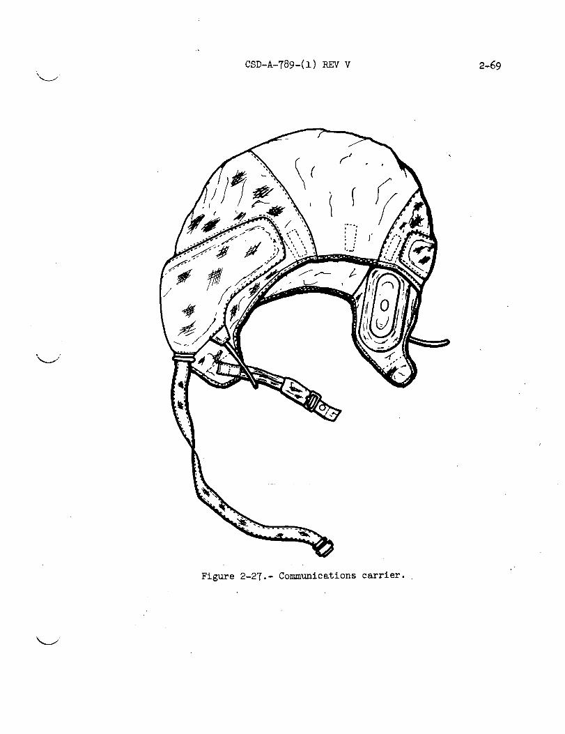
\
CSD-A-789-(1) REV V 2-69
/
Figure 2-27.- Communications carrier.

2-70 CSD-A-789-(1) REV V
A
Center eyeshade
Side eyeshadeVlewport door
Sun visor
Protectlve vlsor
Cover
Latch and catch assembly
Figure 2-28.- Lunar extravehicular visor assembly.

"k.__./ CSD-A-789-(1) REVV 2-71
LEVA to neck ring before latching
.-C_-.._r-::...... . E._
LEVA to neck ring after latching
Figure 2-28.- Concluded.

2-72 CSD-A-789-(1) REV V
The shell assembly is a formed polycarbonate structure to
which the visors, hinge assemblies, eyeshades, latch, and
shell cover assembly are attached. The shell assembly latches
around the pressure helmet at the neck ring, and, when the
latch is 'secured, a rigid connection between the two assem-
blies is assured. Adjacent to the visor hinge, straps con-
structed of polypropylene are employed across the cut-out
support portions of the visor shell to permit flexual dura-
bility and to allow ease in spreading the visor during LEVA
donning.
The shell cover assembly is constructed ,of seven layers of
perforated, aluminized Mylar and six layers of nonwoven Dac-
ron. The layers are arranged alternately to reduce inter-
layer heat transfer. The outer layer or covering is made of
Teflon-coated Beta yarn for additional thermal and fire pro-
tection. Potential scuff areas on the forward edge are rein-
forced with Teflon fabric. Flameproof hook-and-pile fastener
tape (Velcro) is used to attach the collar over the I_VA/ITMG
or LEVA/CLA interface area.
The protective visor is an ultraviolet-stabilized polycarbon-
ate shield which affords impact, micrometeoroid, and ultra-
violet ray protection. It can be positioned anywhere between
the full-UP and full-DOWN positions and requires a force of
2 to h pounds for movement. A coating is added to the inner
surface of this assembly. The elastomer seal on the upper
surface of the stiffener prevents light passage between the
two visors. The protective visor can be lowered independently
of the sun visor, but cannot be raised independently with the
sun visor in the DOWN position.
The inner surface of the polysulfone sun visor has a gold
coating which provides protection against light and reduces
heat gain within the helmet. The visor can be positioned
anywhere between the full-UP and full-DOWNpositions by ex-
erting a force of 2 to h pounds on the pull tabs. The sun
visor cannot be independently lowered unless the protective
visor is in the DOWN position, but it can be raised or low-
ered independently when the center eyeshade is in the full-UP
position and the protective visor is in the DOWN position.
The hinge assemblies located on each side of the LEVA shell
are support and pivot devices for the two visors and eyeshades.
The hinge positions adjust for a proper fit of the visors to
the shell and helmet assemblies and to aid in achieving a
good light seal. Each hinge assembly is comprised of a bolt
extending through a two-plece hub arrangement which supports
V
]

"_-J CSD-A-789-(1) REV V 2-73
dissimilar-material washers, the spacers, and a spring. Ten-
sion on the spring is adjustable and determines the force neces-
sary for visor and side eyeshade movements. After adjustment,
the hinge bolt is safe'tied with lock wire.
The latching mechanism is constructed of stainless steel and
is used to secure the base of the LEVA shell around the PHA
above the helmet neck ring. _ The over-center f_ature of the
latch pulls the two sides of the front portion Of the LEVA
shell structure together and tightens it around the PHA. A
lanyard attached to the actuating tab of the latch and the
shell cover assembly permits easy actuation of the latch with
a gloved hand The lanyard is visible when the collar is
held open.
The eyeshade assemblies are constructed of fiberglass and are
coated with white epoxy paint on the outer surfaces. The
inner surfaces are coated with black epoxy paint. The side
eyeshades are attached to the hinge assemblies and can be low-
ered independently of the sun visor and each other to prevent
light penetration of the side viewing areas, thereby reducing
low-angle solar glare.
The center eyeshade (fig] 2-28) is attached to the LEVA shell
assembly over the shell thermal cover and can be lowered in-
dependently of the side eyeshade assemblies. When sufficiently
lowered, the viewport door may be positioned as required to
reduce soler glare. The viewport door is held in the desired
position by a ratchet mechanism integral with the hinge as-
sembly. The center eyeshade assembly cannot be independently
lowered unless the protective visor and the sun visor are in
the down positions.
2.3.5.10 Dual-Position Purge Valve
The purge valve (fig. 2-29) interfaces with the lower right
exhaust (red) gas connector of the PGA. During contingency
modes of EMU operation, the purge valve is operated in con-
Junction with the oxygen purge system (0PS) to complete an
open-loop gas pressurization and ventilation system. When
activated, the breathable gas flows from the oxygen purge
bottle, through the PGA, and through the open purge valve to
the outside atmosphere. Within the PGA, carbon dioxide is
purged from the oronasal area and passes from the helmet down
through the PGA ventilation distribution system to the purge
valve. One of two purge flow-rate selections is available to
the astronaut. High flow permits a normal 8.1-1b/hr flow of
gas through the PGA with a 4.0-psia differential suit pressure.

2-7h CSD-A-789-(!) 3EY Y
_j
AIi nement tab
Lock tab
Lock pin
/
Orifice selector cap
•Ori riceselectorcap releasebutton
Figure 2-29.- Dual-position purge valve.
V
k_J

CSD-A-789-(1) REV V 2-75
2.3.5.11
2.3.5.12
Low flow permits a normal 4.0-1b/hr flow. A lanyard unlocks
the valve, and the valve is opened by depressing two lock
tabs simultaneously. A rotating cap held by a release button
provides the selection of low-flow-rate or high-flow-rateorifices.
Inflight Helmet Stowage Bag
The inflight helmet stowage bag (IHSB) (fig. 2-30) is used
for temporary helmet stowage in the CM. It is constructed ofa Teflon-coated Beta fabric and conforms to the helmet size.
LEVA Helmet Stowage Bag
The LEVA helmet stowage bag (fig. 2-31) consists of a formed
polycarbonate base, shell assembly, and the necessary straps
and components for attachment of the items to be stowed. The
two-ply shell assembly and the polycarbonate base covering are
made of Teflon-coated Beta cloth. Velcro strips are attached
to the cover of the polycarbonate base to secure the LEVA
stowage bag within the LM. The shell assembly is secured to
the base assembly at the rear by two snaps and a tapered zip-
per closure (gusset) which draws the cover in snugly around
the base. Additional security is provided around the bottom
edge on each side of the gusset by Velcro strips. Polycabonate
rings.formed to the shape of the wrist disconnects are bonded
to the polycarbonate base and provide stowage for the EV gloves.
A polycarbonate retainer is also bonded to the base for stowage
of the EMU maintenance kit. Straps with hook-and-pile fastener
tape on the ends secure the EV gloves and EMU maintenance kit
in position.

2-76 CSD-A-789-(1) REVV
d
Figure 2-30.- Inflight helmet stowage bag.
I

CSD-A-789-(1) REV V 2-77
Figure 2-31.- LEVA helmet stowage bag.

2-78 CDS-A-789-(1) REV V
2.3.5.13 EMU Maintenance Kit
The EMU maintenance kit (fig. 2-32) is a compact, lightweight
assembly containing cleaning, replacement, and repair parts
for inflight maintenance of the A7LB pressure garment assembly
and the extravehicular visor assembly. The EMU maintenance
kit consists of the following items each defined in
subparagraphs :
a. Pocket assembly
b. Seal removal tool
c. Lubricant pouch assembly
d. Pouch assembly
e. Fabric repair patch
f. Fabric repair assembly
The pocket assembly, held closed by hook and pile fastener
strips, folds out to reveal four underlying flaps. The six
items are encased within the flaps.
The seal removal tool is a nylon rod with a preformed tip
which facilitates the removal of the "0" ring seals. A lan-
yard with a pile fastener strip is attached to the tools.
Temporary stowage is accc_plished by engaging the pile strip
with any hook strip.
The lubricant pouch assembly contains eight fluorinated, oil-
saturated pads which are used to lubricate pressure sealing
slide fasteners, seals, and "0" rings. The pads are held in
place in the center pouch of the pocket assembly by whip-stitched Beta thread.
Two 5- by 5-inch sheets of Teflon-coated-yarn Beta cloth are
rolledindividually and placed in the pouch provided.
Two lengths of fiber-glass fabric tape (1 by 36 inches),
wrapped individually to a nylon rod and a Beta-cord lanyard
that connects a strip of fastener tape (hook) to the rod,
comprise the fabric repair assembly. This assembly is stowed
in a pocket provided in the EMU maintenance kit. The tape
may be employed to complete small repairs to layers of the
ITMG or CLA or used in conjunction with the Teflon-coated
Beta cloth when repairs to abraded, cut, or torn areas of the
ITMG or CLA are required.
The pouch assembly consists of six transparent, heat-sealed
pouches. Each pouch is clearly labeled as to its contents.
The entire pouch assembly is attached to the pocket assembly
by snap fasteners.
Amendment 2
ii/5/71
i

CSD-A-789-(1) REV V 2-79
Pocket assembl
Pouch assembly
Fabric repair tape (1)
Fabric repair patch (2) Lubricant pads (4 each)
Lubricant pouch assembly
Seal removal tool assembly
Figure 2-32.-EMUmaintenance kit.
Amendment 2
ii/5/71

2-80 CSD-A-789-(1) REV V
2.3.5.14
The first pouch contains three repair patches made of pressure-
sensitive tape. The second pouch contains five pockets of
sealant which are used in conjunction with the repair patches
to seal accidental punctures in the primary bladder of the PCG.
The third pouch contains a replacement seal for a large wrist
disconnect. The fourth pouch contains three cempartments,
one for a spare PRV "0" ring, one for a spare feedport "0"
ring, and one for a spare gas/water connector "0" ring. The
fifth pouch contains three applicator pad pockets each of
which contains two applicator pads. The sixth pouch containsinstructions for use of the maintenance kit contents.
Helmet Shield
The helmet shield (fig. 2-5) is a transparent, slip-on, pro-
tective cover for the outer, exposed portions of the pressure
helmet assembly. The shield is molded of clear polycarbonate
material and conforms to the outer frontal area of the pres-
sure helmet. A h_le in the lower left facial area permits
the feed-port cover to protrude through the shield. The hel-
met shield protects the pressure helmet fr_n impact or abra-
sion damage during crewman transfer operations between the
command and lunar modules.
INFLIGHT COVERALL GARMENT
The inflight coverall garment (fig. 2-33) is a three-piece
suit consisting of a Jacket, trousers, and boots. The gar-
ment is worn over the CWG during flight in the CM or LM when
the PGA is not required. The inflight coverall garment is
fabricated entirely from lO0-percent woven Teflon fabric.
The detachable pockets of the PGA can be used also on the
coverall garment for stowage of various pieces of equipment.
Restraint tabs hold the CM communications adapter cable in
place. The LM configuration of the coverall garment includes
provisions to pass the LCG adapter through the garment.
Amendment 2
11/5/71
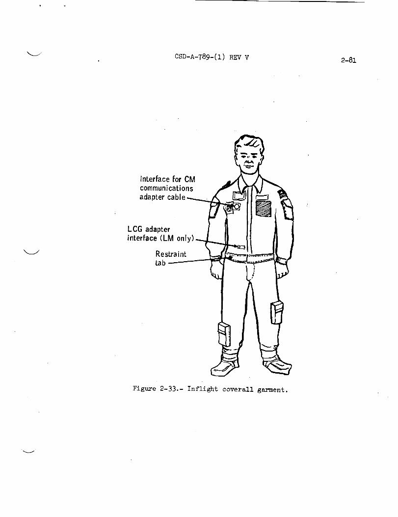
CSD-A-789-(1) REV V2-81
Interface for CM /__,,,,_.communicationsadapter cable . _- =.
LCG adapterinterface (LM onl
Restraint
tab
Figure 2-33.- Inflight coverall garment.

2-82 CSD-A-789-(1) V
2.5 PORTABLE LIFE SUPPORT SYSTEM
The PLSS (fig. 2-34) provides life support for EV EMU activity,
including expendables for metabolic consumption, communica-
tions, telemetry, operating controls, and displays. Although
the -7 PLSS used for Apollo 15 and subsequent missions is
similar to the -6 PLSS used on previous missions, the -7 PLSS
has increased expendables capacity for longer duration mis-
sions (fig. 2-35). The PLSS supplies oxygen to the PGA and
cooling water to the LCG. The PLSS also removes solid and
gaseous contaminants and water vapor frc_a returning oxygen
and thus maintains a clean, dehumidified supply of oxygen.
The PLSS is worn on the back of a suited astronaut in knap-
sack fashion and is attached to the PGA with harnesses.
The major subsystems of the PLSS are the oxygen ventilation
circuit, the feedwater loop, the liquid-transport loop, the
primary oxygen subsystem, the electrical power subsystem, the
extravehicular communications system (EVCS), and the remote
control unit (RCU). The subsystem controls are the main and
auxiliary feedwater tank shutoff valves, the primary oxygen
supply shutoff valve, the water diverter valve, the gas-
separator actuation button, the fan and pump actuation switches,
the communications volume control, the communications mode-
selector switch, and the push-to-talk switch. Subsystem dis-
plays include the oxygen quantity indicator and warning flags
and tones for low suit pressure, low feedwater pressure, high
oxygen flow, and low vent flow. A system schematic of the
-7 PLSS is shown in figure 2-36.
All PLSS components are mounted on the main feedwater reser-
voir and LiON canister assembly. A hard cover fitted over
the assembled unit supports the 0PS mounting plate on top of
the PLSS and the conformal pads. A thermal insulation Jacket
covers the PLSS, except for that portion which is exposed to
the crewman's back. Hard-point mounting holes in the PLSS
sides are used to stow the PLSS in the LM during flight and may"
be Used to mount the buddy secondary life support System (BSLSS)
during EVA.
2.5.1 Oxygen Ventilating Circuit
The oxygen ventilating circuit supplies fresh, cooled oxygen
at 3.5 to 4.0 psia through the PGA. A fan motor assembly
forces the oxygen into the PGA at a flow rate of 5.5 acfm
With a minimum pressure rise of 1.5 inches of water. Suit

_ CSD-A-789-(1) _V V 2-83
Figure 2-34.- Portable life support system.
Amendment 2
11/5/71

2-8_. CSD-A-78_-(1) REV V
o .o. _ _: .m
E_ _ == .. _ a_oo o,. ......_ , _ _ ._ ,_. ,.. j , . • ._ r- _j I II I # I
o..o ooo o /y/ .u_ o ,0 ,0 " .._ _I I
"_-.o'_ _ _ =_, = ×1o_ _- "_l_%_l_\\\_'_\\\\'_&\\
_:=a o _ _I _ _ ,, "-'_111 . / I._-o-o u _ _ _ _ I I= _° _ _ ° = II!III
E _ 0.., >, .- ,.-_ I Im _ t_ _. _j r_ 0 _J -- _ II • ." "
_._. '*" _'=" /! 4/ /_. o / I•_-_ / I//' ,,:. _ = /11/! /
*!u_ _1 / o _. m_ ":,, "-C_ . eq " _--I o
,., _ _ I .-r ::: 5_ _, -fJ -15.... XX _ _ --_J _I OOLI. I.I.
.-- _1 '_ a,31
__1t,a e,, _ I
I ! I
O O O
O O OO ,O
O_
OO
r_
un _
o_
l'i'i:-7,I Ii I o
0 0 0(3 0 0od O0 ,_
JLI/nl_ ' a:leJ :_!loqelauJe_eJ_A V

CSD-A-789-(1) REV V 2-85
z
Amendment 2
zi15171

2-86 CSD-A-789-(1) REV V
inlet dewpoint temperature is 50 ° F (or below), and suit in-
let oxygen temperature is approximately 77 ° F (nominal).
After passing through the suit vent system, the oxygen re-
turns to the PLSS through the PLSS inlet connector.
In the PLSS, the oxygen passes through the contaminant con-
trol assembly where a bed of activated charcoal removes odors
and a bed of lithium hydroxide granules removes carbon dioxide.
A peripheral Orlon filter removes foreign particles.
From the contaminant control assembly, the oxygen passes
through the sublimator. The sublimator cools the oxygen and
condenses the water vapor. A sensor at the sublimator outlet
measures sublimator outlet gas temperature for telemetry.
From the sublimator, the oxygen passes through a water sepa-
rator which removes, at a maximum rate of 0.508 lb/hr, the
condensate water entrapped in the oxygen flow. The conden-
sate is ducted from the separator to the outer sections of
the main and auxiliary feedwater tanks through the water shut-off and relief valve.
The oxygen from the separator returns to the inlet of the fan
motor assembly. A carbon dioxide sensor shunted around the
fan motor assembly samples the oxygen vent flow and monitors
the carbon dioxide level for telemetry. Make-up oxygen from
the primary oxygen subsystem enters the oxygen ventilating
loop Just downstream of the fan outlet. (The fan motor as-
sembly operates at 18 600 ± 600 rpm with an input voltage of
16.8 ± 0.8 V dc.) Figure 2-37 is a schematic representation
of the oxygen ventilating circuit.
V
2.5.2 Primary Oxygen Subsystem
The rechargeable, primary oxygen subsystem of the -7 PLSS is
shown schematically in figure 2-38. The subsystem consists
of a primary oxygen bottle, a fill connector, a pressure reg-
ulator, a shutoff valve, and connecting tubing. The primary
oxygen bottle is a welded stainless-steel cylinder with cry-
ogenically formed hemispherical ends. High-pressure,
corrosion-resistant, stainless-steel tubes and fittings con-
nect the primary oxygen bottle to the oxygen regulator assem-
bly. The crewman actuates a shutoff valve to the primary
oxygen regulator assembly by an operating lever located at
the lower-right-front corner of the PLSS. When the PLSS is
not in use or when the primary oxygen subsystem is being
charged, the oxygen shutoff valve is closed.

CSD-A-789-(1) REVV 2-87
=
m
,IoJ
n
1 ' _ ..... 0 i
-- i_DJ
r_ I'-'LLI_
0
0
.Pl_J
=I0pl
,'-t
4._
fI
ICq
.el

2-88 CSD-A-789-(1) REV V
e-
l "-I_.;_ • _ ", o• _-l-Jm._._-o N'z E
-- oio --_
Q.
O
..J
o
f-
ii
_p
Oc_
+I _
E
wm
o
c_
m
t_
bD
O
I
df¢3
!(Xl
.el

--J CSD-A-789-(1) REV V 2-89
The initial ground charge and the LM recharge pressure for
the first four recharges is 1410 + 30 psia. Recharge pres-
sure for the fifth recharge is 1310 psia minimum. The
charging process (except for the fifth recharge) gives a
minimum of 1.340 pounds of usable oxygen for EVA at 1380 psia
and 70 ° F, This oxygen supply is ample for a 5-hour EVA at
1200-Btu/hr metabolic load plus 300 Btu/hr of EMU leakage.• , . .
Make-up oxygen flows from the primary oxygen bottle through
the shutoff valve and regulator to the oxygen ventilating
circuit. The regulator provides a pressure of 3.85 + 0.15 psia
to the vent circuit. An orifice limits the flow to a maximum
of 4.0 pounds per hour at 70 ° F with a supply pressure of
1500 psia, thereby protecting the PGA from overpressurization
if the regulator fails open. A primary oxygen pressure
transducer at the oxygen bottle outlet provides electrical
signals to the RCU oxygen quantity indicator and to the PLSS
telemetry syste m . If oxygen flow exceeds 0.50 to 0.65 pound
per hour, an oxygen flow sensor downstream of the regulator
gives an audible tone until the flow decreases to 0.50 to
0.65 pound per hour (a continuous high flow of 0.50 to
0.65 pound per hour for 5 seconds is needed to cause actua-
tion). Two additional pressure transducers in the primary
oxygen subsystem are used to monitor PGA pressure. One is
used for telemetry monitoring, and the other activates an
audible warning tone when pressure drops below 3.10 to
3.40 psid. The primary oxygen subsystem is recharged through
a leak-proof, self-sealing, qulck-dlsconnect fill connector.
2.5.3 Liquid Transport LooD
The recirculating liquid transport loop provides thermal con-
trol for the crewman by dissipating heat through the subli-
mator. Warm transport water from the LCG enters the PLSS
through the MWC. The water then passes through a gas sepa-
ratar which can entrain a minimum of 30 acc of gas. Should
cooling performance degrade because of additional gas, the
crewmen can vent the trap manually to ambient and ready it for
further entrapment. From the separator, the transport water
enters the pump which forces the water through the sublimator
for cooling. The pump provides a minimum flow of 4.0 pounds
per minute with a pressure rise of 1.9 psi across the inlet
and outlet portions of the PLSS MWC. The cooled water from
the sublimator passes through the fan motor cooling Jacket
and then through the diverter valve and out of the MWC.

2-90 CSD-A-789-(1) REV V
The crewman regulates coolant flow with the diverter valve.
In the minimum position, most of the flow is diverted past
the sublimator. In the maximum position, all of the flow
from the LCG passes through the sublimator. The intermediate
position provides midrange cooling. The liquid transport
loop is interconnected to the feedwater loop by a check valve
which permits make-up water to enter the transport loop up-
stream of the pump.
A differential temperature transducer senses the differen-
tial temperature of LCG water entering and leaving the PLSS,
and a temperature transducer senses LCG inlet temperature.
Both transducers provide electrical signals for telemetry.
A schematic of the liquid transport loop is shown in
figure 2-39.
2.5.4 Feedwater Loop
The feedwater loop is shown schematically in figure 2-40.
This loop contains a primary feedwater reservoir and an aux-
iliary feedwater reservoir. The reservoirs supply water to
the porous plate of the sublimator and collect condensation
supplied by the water separator.
Each reservoir is a bladder-type rechargeable tank. Minimum
capacities are 8.40 pounds of water for the primary reservoir
and 3.06 pounds of water for the auxiliary reservoir. Feed-
water from both reservoirs flows through a manually operated
shutoff and relief valve. This valve, when in the off posi-
tion, acts as a relief valve to prevent overpressurization of
the feedwater reservoir. Feedwater then enters the porous
plate of the sublimator. The feedwater forms an ice layer
on the surface of the porous plate which is exposed to vacuum.
Heat from the liquid transport loop and oxygen ventilating
circuit is conducted to the porous plate and is dissipated by
sublimation of the ice layer. A flow-limiting orifice be-
tween the shutoff and relief valve and the sublimator prevents
excess water spillage from the sublimator porous plate during
startup or during a possible sublimator breakthrough (a con-
dition in which ice fails to form on the surface of the porous
plate). A separate shutoff and relief valve isolates the aux-
iliary feedwater reservoir from the primary feedwater reser-
voir during normal operation. If the primary feedwater
supply is depleted during EVA, the crewman can open the aux-
iliary reservoir shutoff and relief valve to provide additional

CSD-A-789-(1) REV V 2-91
Fan cooling jacket H/X
Feedwater loop check valve
Figure 2-39.- Liquid transport loop.

CSD-A-789-(1) REV V2-92
c'-C:
0
o_0
r"l
II)
O3
!
!
or-t

_ CSD-A-789-(1) REV V 2-93
cooling. Both the primary and auxiliary feedwater shutoff
and relief valves are actuated by handles at the lower-right-
front corner of the PLSS. The feedwater reservoirs also pro-
vide make-up water to the liquid transport loop via a checkvalve.
Oxygen ventilating loop pressure forces the condensate from
the water separator into the space between the reservoir
housings and the bladders of both feedwater reservoirs. This
action causes a pressure of 3.3 psid on the feedwater bladder.
The feedwater reservoirs are recharged and drained through
fill and drain connectors attached to both sides of the blad-
ders. Recharge and drainage are performed simultaneously.Each bladder contains a vent line with a vent connector.
During recharge, the vent connector is connected to a vacuum
line to remove entrapped gas and assure a full charge.
A feedwater pressure transducer Just upstream of the subli-
mator provides telemetry monitoring to identify sublimator
breakthrough or feedwater depletion. The transducer also
contains a switch which actuates an audible warning and the
low feedwater pressure warning flag on the RCU if feedwater
pressure drops to 1.2 to 1.7 psia.
2.5.5 Electrical Power Subsystem
The electrical power subsystem provides dc electrical power
through appropriate connectors to the fan motor assembly, the
pump motor assembly, and for communications and instrumenta-
tion. A 16.8 ± 0.8-V dc, ll-cell, silver-zinc alkaline bat-
tery supplies the power.
The minimum capacity of the -7 PLSS power supply is 387.5 watt-
hours which is for a battery shelf llfe of 2 years.
The sliding pin locking device, shown in figure 2-41 _,holds
the battery in place. Between extravehicular activities, a
crewman can release this device to replace the battery.

CSD-A-789-(1) REVV
O.
©
°_
0
bO
00
pq
I
IOJ
V

k_/ CSD-A-789-(1) REV V 2-95
Electrical power requirements are as follows.
Maximum._ watt Nominal I watt
Pump i0.0 8.4
Fan 32.5 21.8
EVCS 12.8 10.9
Current limiters protect selected electric circuits against
overcurrents which could cause fires. These limiters pass
transient current in excess of a normal load but open at sus-
tained overload. Table 2-X lists current limiter ratings.
Transducers provide signals for telemetry of battery current
and voltage.
k._./
2.5.6 Extravehicular Communications System
The EVCS (fig. 2-42) provides the following basic capabilities:
a. Simultaneous and continuous telemetry from two extrave-
hicular crewmen
b. Duplex voice communications between earth and one or
both of the two extravehicular crewmen
c. Uninterruptable voice communications between the crewmen
d. Thirty telemetry channels, 30 by 1-1/2 pam, per
each extravehicular communicator (EVC) with 26 channels
available for status information
e. Separate subcarrier frequencies for continu-
ously monitoring each crewman's ECG during EVA
f. An audible alarm for i0 ± 2 seconds in the
event of an unsafe condition (if the EVC mode-selector
switch position is changed and the unsafe condition still
exists, the warning tone will come on again for i0 ±
2 seconds.)
The EVCS consists of two extravehicular communicators (EVC-I
and EVC-2) which are an integral part of the PLSS. The EVC-I
consists of two amplitude modulation (AM) transmitters, two

2-96 CSD-A-789-(1) REVV
TABLE2-X.- PLSS/EVCSCURRENTLIMITERRATINGS
Component Current ratings of -7 configuration, A
Fan
Pump
ECG
Left microphone
Right microphone
Vent flow sensor
Time delay module
High 02 flow sensor
EVC(dual-primary modevoltage regulator)
EVC(secondary modevoltage regulator)
EVCtelemetry
Alarm module
Voltage regulators
Time delay module (forhigh 02 flow sensor)
EVCwarning tone generator
22-gage wire --current protection isnot provided a
22-gage wire m current protection isnot provided a
1/4 (with series 32.4- to 39.2-ohm,i/2-watt resistor)
1/8 (with series 32.h- to 39.2-ohm,i/2-watt resistor)
1/8 (with series 32.4- to 39.2-ohm,1/2-watt resistor)
1/16
1/16
None (unit has built-in current limiter)
2
2
1
1/2
3/4
1/16
1/16
V
aThe maximum overload current of 22-gage copper wire is 40 amps.
i I

CSD-A-789-(1) REV 37 2-97
[ II X
Irj
v
4._
p,-H
o.r,I
o
,H
I
Od
I('d
.r4

2-98 CSD-A-789-(1) REV V

k..j, CSD-A-789-(1) REV v 2-99
k._./
AM receivers, one frequency modulation (FM) receiver, signal-
conditioning circuits, a telemetry system, a warning system,
and other components required for system operation. The
EVC-2 is similar to the EVC-I except that the EVC-2 has anFM transmitter instead of an FM receiver.
Each EVC Can be controlled manually by a four-position switch
for each of the following modes of operation.
a. Off (0) c. Primary (A)
b. Dual (AR) d. Secondary (B)
The dual mode is the normal operating position of the switch.
In this mode, the EVC-2 transmits a 0.3- to 2.3-kHz voice
signal and two interrange instrument group (IRIG) subcarriers
(3.9 and 7.35 kHz) via a 279-MHz FM transmitter. The trans-
mitter has an unmodulated output in excess or 500 mW. The
composite signal from the EVC-2 is received at EVC-1, mixed
with an additional 0.3- to 2.3-kHz voice signal and two ad-
ditional IRIG subcarriers (5.h and 10.5 kHz), and transmitted
to the LM on a 259.7-MHz AM link. The composite signal of
two voice and four subcarriers is then relayed from the LM
to the earth via S-band. The EVC-2 also receives EVC-1 out-
put (which includes the original EVC-2 transmission) on a
259.7-MHz receiver; thus, a duplex link between the two EV
crewmembers is established. Communications signals are trans-
mitted from the earth to the LM via S-band and are then re-
layed to both astronauts on the 296.8-MHz AM link.
The outputs of the FM and AM receivers are summed with an
attenuated input voice signal and applied to the earphones.
The audio output levels of both receivers are individually
controlled by separate volume controls located in the RCU
affixed to the chest of the PGA. The input voice signal is
attenuated l0 dB to provide a sidetone for voice level
regulation.
The dual mode provides uninterruptable duplex voice communica-
tions between the crew-members and the LM/earth linkup plus
simultaneous telemetry fr_n each crewmember via relay throughEVC-I.
In the event of a malfunction in the dual mode, the system
is backed up by the primary- and secondary-mode positions.
(Note that both crewmen should never be in the primary or
secondary modes simultaneously. Severe distortion and inter-
ference will occur, and communications will be temporarilylost.)

CSD-A-789-(1) REVV2-100:
In the primary and secondary modes, duplex voice communica-tion is maintained between the two crewmenand the LM. Thesecondary mode, however, has no telemetry capability. Also,the secondary-mode transmitter is inoperative unless activatedby the volce-operated switch or the manual switch. The trans-mitter is continually operative in the dual and primary modes.
The telemetry unit contains a warbling 1.5-kHz warning tone.Any one of four problems (high oxygen flow, low vent flow,low PGApressure, or low feedwater pressure) will key thetone and alert the astronaut to check the remote control unitfor a visual indication of the problem area to be investigated.The operation of the warning system is independent of modeselection.
Each telemetry system can accommodateup to 26 commutator
channels (table 2-XI) at l-l/2 samples per second and one
ECG channel and provides a data accuracy of 2 percent root
mean square.
2.5.7 Remote Control Unit
The RCU (fig. 2-43) is a chest-mounted instrumentation and
control unit which provides the crewman with easy access to
certain PLSS/EVCS controls and displays. Controls include a
fan switch, a pump switch, a communications mode-selector
switch, a push-to-talk switch, and two communications volume
control knobs. Displays include an oxygen quantity indicator
and four active status indicators (warning flags). A fifth
status indicator is provided, but is not presently used. The
status indicators are illuminated by beta particle capsules
requiring no electricity. Any one of four problems (high
oxygen flow, low vent flow, low PGA pressure, or low feed-
water pressure) will cause a cylinder to rotate and reveal
the illuminated warning symbol underneath. Simultaneously,
the warble tone in the EVCS is activated to alert the crewman

HE-_O0HD_
CD
E_
O
E_
¢DH
O_D
¢D
CO
I
IC_J
_q
E-_
O
O
4-)
O¢D
O_
O
_Jq bD
°_
D_
¢)bD
O
40ED
H
O
OJ
Lfk
CSD-A-789-(1) REV 5
CJ O
o L_
O4
OJ
kOC_J
C_J
Od _ _ O4 _4h-_4
C_
kid
o
o0c_J
c_oJ
r-d
O© ._
+_ _ _o0 ._
•_ ,'-IZl -_ Cd
© ,_ _
o ul!
o ,-t
©
0 0 0 0 0
0 0 0 0 0
kOaO
,-t
0-p
O_
kOcO
O+_
O__4
Lr_
O40
O
_D
•_I b_-
o c_ c;t._ (5)
o _ _ o4o
O O b_U_ 4-_ 4_ °
OJ 0 0 ,'-I
0Lf'x
0-p
0
0
oooh
0
oc)
o0cyx
o-p
oo
.-d-
,,-I
o
o.p
o
(D
_D
_D
P_
gP_
©
-io _D o .©
o _ __ _ _ _ o_ o
u_
H
0_p
o
0
o
,---I
S
°1-t •
_D_c_,r-IN0 _D
ffl_ mo ©
r_
2-101
o
©
o
v
0
o
cO

2-102 CSD-A-789-(1) REV V
PLSS oxygen quantity iindicator (see part bof this figure)
Mode
select switch
-6 4 positions--_
OPS actuator---
(
Status indicator _.
Fan switchPump switch on side(not vi_
Pu sh-to-tal k sw itch
Camera mount
Volume control on bottom
(not visible)
(a) Pictorial view of main elements.
Figure 2-_3.- Remote control unit.
V

CSD-A-789-(1) REV 5 2-103
112
Each increment of indicator represents 68 psia.
(b)
Marking
0
i14
i/2
314
F
Oxygen bottle pressure range,• a
psla
150 + 68
490 +_68
825 +_ 68
1163 +_68
1500 ± 68
aWith RCU in a horizontal position and zero g.
Oxygen quantity indicator markings and accuracies.
Figure 2-_3.- Continued.

2-io4 CSD-A-789-(1) REVV
I
3.5 in. max._ Pump
__1_1__. _ switch
Push-to-t.alk switch 7
Iflo
L
8.5 in. max.
(overall) Zcamer a
_Mod_ e mount 4selector switch
------5.88 in. --------
__ 2.40 in.
7.10 in.
. 7.44 in. max.------(overall)
(c) Dimensions.
Figure 2-)43.- Concluded.
II

CSD-A-789-(1) REV V 2-105
to check his RCU and determine the problem area.
symbol is a key to corrective action as follows.
Each warning
Function
High oxygen flow
Low PGA pressure
Low vent flow
Low feedwater
pressure
Indicator label
02
Pressure
Vent
H20
Symb o !
0
0
P
A
Indicated action
Actuate 0PS
Actuate OPS
Purge
Open auxiliaryfeedwater shut-
off valve or use
BSLSS as required
2.6
In addition to the above functions, the RCU provides a mount-
ing point for the OPS actuator cable and the camera bracket.
OXYGEN PURGE SYSTEM
The OPS (fig. 2-H4) supplies the EMU with oxygen purge flow
and pressure control for certain failure modes of the PLSS
or PGA during EVA. In the event of a PLSS failure, the OPS
flow is regulated to 3.7 i 0.3 psid for 30 minutes to provide
breathing oxygen to the crewman, to prevent excessive carbon
dioxide buildup, and to provide limited cooling. In this
mode, the crewman sets his purge valve in the high-flow posi-
tion (8.1 pounds per hour). In a second mode, the 0PS may
be used to provide make-up flow to the PLSS oxygen ventilating
circuit via the PGA at flow rates of 0.07 to 2.0 pounds per
hour. Finally, the OPS can be used in conjunction with the
BSLSS (as described in section 2.7) to provide a 1.25-hour sup-
ply of purge flow for a crewman with a failed PLSS. For this
mode, the crewman sets his purge valve in the low-flow posi-
tion (4.0 Ib of 02 per hour).
In the lunar EVA configuration, the OPS is mounted on top of
the PLSS (fig. 2-1). For normal EV activity from the command
module, the OPS is worn in the helmet-mounted mode as shown
in figure 2-45. During contingency EV transfer from the lunar
module, however, the OPS is attached by straps to the lower
front torso of the PGA (fig. 2-46).

2-106
0 '- L.
CSD-A-789-(_l). REV Y
o
Ie-
O
b_.,-4
Oo
!
f
h0
b_
O
I
_4
IC_
V
_i] !ii'!¸

k_J CSD-A-789-(1) RE V 2-107

2-108 CSD-A-789-(1) REV V
Actuator@
@@
@
OPS
OPS umbilical
Figure 2-46.- The OPS worn in the torso-mountedcontingency mode.
%.,

CSD-A-789-(1) REV V 2-1o9
2.7
A schematic representation of the 0PS is shown in figure 2-47.
The 0PS consists of two interconnected, spherical, high-
pressure oxygen bottles (total of 5°1 pounds of usable oxygen
at 5880 +- 80 psia and 70 ° F), a pressure regulator assembly,
a fill fitting, a high-pressure gage, a delta-pressure gage,
a suit connector and hose, a suit connector stowage plate,
a shutoff valve, and an actuator cable and handle. The 0PS
has no communications capability, but provides the hard mount
for the PLSS antenna. The 0PS used for Apollo 15 and subse-
quent missions differs from the OPS used on Apollo 14 in that
attachment points for the PLSS harnesses have been moved to
permit helmet mounting. Also the oxygen outlet temperature
control capability incorporated in the 0PS for all missions
through Apollo 13 has been deleted. Thus the heater, con-
trol circuitry, terminal board, temperature sensor, power
switch, and battery have been removed.
The 0PS is not rechargeable during a mission. The high-
pressure gage is used to monitor bottle pressure during
ground charge and during preoperational checkout. The delta-
pressure gage is used during preoperational checkout to verify
regulated flow through a O.hh- to 0.70-pound-per-hour orifice
mounted on the connector stowage plate.
BUDDY SECONDARY LIFE SUPPORT SYSTEM
The BSLSS enables two EVA crevmen to shsre the water cooling
provided by one PLSS following loss of cooling capability in
the other PLSS. The system is shown schematically in fig-
ure 2-48 and in use by two crewmen in figure 2-h9. The BSLSS
is made up of six principal components.
a. Two water hoses 8-1/2 feet long and 3/8 inch inside diam-
eter to carry the coolant flow between the good PLSS and
the other crewman
b. A normal PLSS water connector on one end of the double
hose
C. A flow-dividing connector on the other end of the double
hose. consisting of an ordinary PLSS water connector
coupled with a receptacle to accept a PLSS water connector
d. A 4-1/2-foot restraint tether with hooks for attachment
to the PGA 124 restraint loops

2-110 CSD-A-789-(1) REVV
e-e-_U
e"
0'1
o>uJ
.rq+_
@
O59
_n
hD
_Dh0
O
!
_0
b0
V
V

CSD-A-789-(1) REV V 2-111

2-n2 CSD-A-_7_-(1)_ VV
Multiple water
connector
Electrical
umbilical
PLSS outlet
PLSS 0 2 inlet
0 2 inlet
•PLSS water Purge valve
Tethers
Water
umbilical
Operational PLSS Nonoperational PLSS
Figure 2-49 ._ Buddy secondary life support system connected.

CSD-A-789-(1) REVV 2-113
e. A thermal sheath the length of the hoses with tetherbreakouts 2 feet from each end
f, A thermal pouch for stowage of the assembly on the PLSS
during EVA and in the I/_ cabin during non-EVA periods
(fig. 2-50)
The BSLSS hose stowage is illustrated in figure 2-50.
2.8 PRESSURE CONTROL VALVE
2.9
A pressure control valve (PCV) controls PGA pressure during
normal EV transfer from the command module. This is a re-
lief valve installed in one of the PGA outlet gas connectors
prior to EVA. A purge valve is installed in the other out-
let gas connector. Oxygen is supplied from the command mod-
ule environmental control system at a flow rate of i0 to
12 pounds per hour via an umbilical to one of the PGA gas
inlet connectors. The OPS, worn in the helmet-mounted con-
figuration, provides a backup oxygen supply." The PCV con-
tains a spring-loaded poppet which senses suit pressure and
unseats, dumping a s1_fficient amount of suit oxygen to space
to maintain suit pressure in the 3.5- to h.0-psid range.
The PCV is also sized to prevent suit pressure from falling
below 3.2 psid in the event the poppet fails open. The PCV
is sho_ in a schematic representation in figure 2-51.
PLSS FEEDWATER COLLECTION BAG
Deleted
Amendment 2
11/5/71

2-ii_ CSD-A-789-(1) REV V
OPS
_SLSSstowage
bag
PLSS Shoulder
harness
Waistharness
V
Figure 2-50.- BSLSS hose stowage.

CSD-A-789-(1) R_ V 2-115
o
r_
O
\[
_I 0 H
r-t o
o o| °r.t
°_
0
o
-o
r-Ioh
+_
0
t/lm
I
,--t
IoJ
(11
oH
II.'-
i ,_ Zi| c
II. _- /'--I _
e-
e-
n

2-116 CSD-A-789-(1) REV V
2. i0 BIOMEDICAL INSTRU_4ENTATION SYSTEM
The biomedical instrumentation system (fig. 2-52) is attached
to either the CWG or the LCG and contains the necessary in-
strumentation for crew status check. The instrumentation
connected to the PGA electrical harness consists of an ECG
signal conditioner, ZPN signal conditioner, dc-dc converter,
and axillary and sternal electrodes.
2.10.1 Electrocardio6ram Signal Conditioner
The ECG signal conditioner has a signal wave ranging between0 and 5 volts peak to peak which is representative of inflight
heart activity.
2.10.2 Impedance Pneumo6ram Signal Conditioner
The ZPN signal conditioner and associated electrodes provide
flight measurement of transthoracic impedance change. A pair
of electrodes is used to measure respiration rate over a wide
dynamic range of activity.
2.10.3 The dc-dc Power Converter
The dc-dc power converter delivers +iO- and -10-volt power
to each signal conditioner from the single-ended 16.8-volt
power source.
2.10.4 Electrodes
The electrodes are attached directly to the skin with an ad-
hesive disk filled with conductive paste. The ECG sternal
electrodes are attached to the ECG signal conditioner and
the ECG axillary electrodes are attached to the ZPN signal
conditioner.
Amendment 2
11/5/71

CSD-A-789-(1) REV V2-117
k
@

V
"i

3.0
CSD-A-789-(1) REV V
EXTRAVEHICULAR MOBILITY UNIT SYSTEMS
3-1
3.1 PRIMARY PRESSURIZATION AND VENTILATION
The EMU primary pressurization and ventilation system
(fig. B-l) is a closed-loop gas system which provides a hab-
itable environment for the astronaut during Apollo EVA mis-
sions. A precharged oxygen bottle (1410 ± 30 psia) and
pressure regulator pressurizes the system to 3.85 ± 0.15 psig
and supplies the system with make-up oxygen to satisfy a
1200-Btu/hr metabolic load plus an E_ leakage factor for a
5-hour EVA design mission. The pressurized, breathable gas is
forced through the loop at a rate of 6.00 elm by a circulation
pump. The circulated gas flows through the pressurizable portion
of the PGA consisting of a TLSA, helmet, and a pair of gloves.
Within the pressurizable envelope, a ventilation distribution
system directs the gas flow from the inlet connector to the
helmet and the torso, if desired, down over the body to the
limb extremities, then through noncrushable ducts to the out-
let gas connector. The exhaust gas flows from the PGA to the
PLSS through an umbilical.
Within the PLSS, the gas passes through a contamination-
control assembly where odors are removed by activated char-
coal. Carbon dioxide is removed by chemical reaction with
LiOH, and foreign particles are filtered out by a peripheral
Orlon filter. The oxygen passes from the contamination-
control assembly to a s1_limator which then cools the circu-
lated oxygen. The cooled oxygen passes from the sublimator
to the water separator where excess water entrained in the
cooled oxygen is removed at a maximum rate of 0.508 ib/hr.
The oxygen passes frc_n the water separator to the fan/motor
assembly for recirculation.
If a hypodermic injection is required, it is administered
through the biomedical injection patch located on the left
thigh. The patch is a self-sealing disk which prevents suit
leakage as a result of the injection.
Suit pressure can be monitored continuously on a pressure
gage installed on the left wrist of the PGA. The dial-
indicating instrument is calibrated from 2.5 to 6.0 psid. In
the event of suit overpressure, a pressure relief valve,
located on the right thigh of the EV PGA and the left wrist i
Amendment 2
11/5/71
3-2 CSD-A-789-(1) REVV
To be determined
Figure 3-1.- EMUprimary pressurization and ventilation system.

CSD-A-789-(1) REVV 3-3
!cone of the CMPPGA, opens at pressures of 5.00 to 5.75 psldand reseats at not less than h.6 psid. iThe flow of oxygen through the PLSS regulator assembly is
limited to a maximum of 4.0 lb/hr at 1500 psia to protect the
PGA against overpressurization in the event of a failed-open
regulator. This is accomplished by an orifice between the
regulator and the prime oxygen bottle and fill connector.
The fill connector is a leak-proof, self-sealing, quick-
disconnect connector used for recharging the primary oxygen
subsystem. Recharge time from a lh25-psia source at 0° to
60 ° F is a nominal 75 minutes. An oxygen flow sensor gives
an audible tone when PLSS primary oxygen flow exceeds a
0.50 to 0.65 lb/hr band and will remain actuated until the
flow decreases to 0.50 to 0]65 lb/hr (a continuous high flow
of 0.50 to 0.65 for 5 seconds is needed for actuation). A
primary oxygen pressure transducer provides electrical signals
to the oxygen quantity indicator for crew visual read-out and
to the telemetry system of the PLSS.
Two additional pressure transducers are incorporated in the
primary oxygen subsystem to monitor the PGA pressure. One
transducer is used for telemetry monitoring, and the other
activates an audible warning tone when PGA pressure drops be-
low 3.10 to 3.40 psid.
3.2 LIQUID COOLING SYSTEM
The EMU oxygen pressurization and ventilation system removes
body heat by carrying evaporated body perspiration from the
PGA. To reduce bodY fluid loss and increase body cooling
efficiency, the liquid cooling system is employed for trans-
porting metabolic heat from the PGA. The liquid (water)
cooling system (fig. 3-2) is a closed-loop system fed by a
pressurized water reservoir. The reservoir is pressurized by
the EMU pressurization and ventilation system, and a pump cir-
culates the water through the closed-loop system at a nominal
rate of h.0 ib/min.
The water supplied by the PLSS passes through the inlet pas-
sage of.the multiple water connector and circulates through
the manifold and a network of polyvinylchloride tubing con-
tained in the LCG. During the circulation process, the heat
within the PGA is transferred by conduction to the water
which returns through the outlet passage of the multiple
Amendment 2
11/5/71

3-a CSD-A-T89-(1) REV V
V
To be determined
Figure 3-2.- EMU liquid cooling system.
NASA _ MSC
it

CSD-A-789-(1) REV V 3-5
water connector to the PLSS for cooling. The water within
the PLSS is circulated through the sublimator to provide the
cooling. The sublimator is supplied with expendable feed-
water from the feedwater reservoir.
The feedwater is enclosed by a collapsible bladder within the
reservoir with the exterior of the bladder exposed to the
ventilation loop pressure through the water separator. This
pressure provides the force required to supply feedwater to
the sublimator. It also enables the portion of the feedwater
reservoir external to the bladder to be used for the storage
of waste water removed from the ventilation loop.
"_" _'_ U.S. GOVERNMENT PRINTING OFFICE: 1972--779-261/291

_j
V
i i_