apollo experience report pressure vessels · apollo experience report ... a vessel failure, ......
TRANSCRIPT

TECHNICAL
ab-
APOLLO EXPERIENCE REPORT - PRESSURE VESSELS
by Glenn M . Ecord
Manned S'acecrdft Center Houston, Texas 77058
NASA T N
L
D-6975
'
NATIONAL AERONAUTICS AND SPACE ADMINISTRATION WASHINGTON, D. C. SEPTEMBER 1972
https://ntrs.nasa.gov/search.jsp?R=19720024230 2018-07-03T22:37:47+00:00Z

I
18. Distr ibution Statement
1 Report No
NASA ?Tu' D-0972
APOLLOEXPERIENCEREPORT PRESSURE VESSELS
2 Government Accession No 3 Recipient's Catalog No
4 Tit le and Subtitle -
5 Reoort Date
National Aeronautics and Space Administration Washington, D. C. 20546
7. Author(s)
Glenn M. Ecord, MSC
9. Performing Organization Name and Address
Manned Spacecraft Center Houston, Texas 77058
14. Sponsoring Agency Code l------
8. Performing Organization Report No.
MSC S-327 10. Work Unit No.
914- 13-20-06-72 11. Contract or Grant No.
5. Supoiementary Notes The MSC Director waived the use of the International System of Un i t s (SI) for this Apollo Experience Report because, in h i s judgment, the use of SI units would impair the usefulness of the report o r result in excessive cost.
2. Sponsoring Agency Name and Address
6. Abstract
The Apollo spacecraft p ressure vessels, associated problems and resolutions, and related ex- perience in evaluating potential problem a reas a re discussed. Information is provided that can be used as a guideline in the establishment of baseline cri teria fo r the design and use of light- weight pressure vessels. One of the first practical applications of the use of fracture-mechanics technology to protect against service failures was made on Apollo pressure vessels. Recommen- dations a r e made, based on Apollo experience, that a r e designed to reduce the incidence of fail- u re in pressure-vessel operation and service.
13. Type of Report and Period Covered
Technical Note
17. Key Words (Suggested by Author ls) )
* Nondestructive Testing 'Vessel Management ' Safety Factors
* P r e s s u r e Vessels ' Quality Assurance
' Apollo Program
Frac ture Mechanics * Vessel Analysis
19. Securlty Ciassif. (of this report1 20. Security Classif. this page)
None None 2 1 . NO. of Pages 22. Price
27 $3.00
' For sale by the National Technical Information Service, Springfield Virginia 22151

APOLLO EXPERIENCE REPORT
PRESSURE VESSELS
By G l e n n M. Ecord Manned Spacecraft Center
SUMMARY
Apollo spacecraft pressure vessels were designed using safety factors as low as 1. 5 to save weight. The relatively low safety factors, combined with the criticality of a vessel failure, required that stringent fabrication requirements and controls be main- tained throughout the vessel programs to ensure production of quality vessels. Addi- tionally, posffabrication analytical techniques were introduced to confirm and control safe vessel operation.
No problems were experienced that were a direct result of reduced safety-factor levels. Major vessel problems involved isolated instances of materials incompatibility with pressurants, of inadequate process control, and of materials anomalies. However, it has been shown that reduced safety factors may increase the susceptibility of mate- rials to s t r e s s corrosion or incompatibility problems.
The resolution of each problem provided a resultant increase in the knowledge necessary to ensure safe operation as reflected in several recommendations concerning design, fabrication, use, and management of lightweight pressure vessels. Specific identification and assignment of responsibility for spacecraft pressure vessels was nec- essary to accomplish effective control of vessel fabrication and use.
INTRODUCTION
The Apollo spacecraft pressure vessels comprise a significant part of the dry structural weight of the spacecraft. Seventy-one vessels are used in the command module (CM), service module (SM), and lunar module (LM); the launch escape system (LES) uses three rocket motor cases that become pressurized when fired. Each of the vessels constitutes a potential single failure point for critical subsystems and contains stored energy at operating pressures that could be catastrophic to the spacecraft should rupture occur.
Historically, high safety factors (ratio of design burst pressure to maximum de- sign operating pressure) have been used in the design of commercial pressure vessels to compensate for unknowns in pressure-vessel fabrication and service. A safety

factor of 4 .0 was considered a minimum. In the early 1960's, the U. S. Air Force de- veloped a new technology for fabrication methods and materials control by means of stringent specification requirements that minimized r isk and justified a safety factor of 2.0 fo r pressure vessels used in high-performance aircraft.
Safety factors of 2 .0 on some pressure vessels used in the Apollo spacecraft sys- tems became impracticable because of the associated weight penalty. As a result, sev- e ra l Apollo pressure vessels were designed to a minimum safety factor of 1. 5. This unprecedented minimum safety factor for vessels in manned systems combined with the criticality of a vessel failure required that every known precaution be taken in fabrica- tion and use to ensure safe vessel operation. Despite the precautions, a few failures and related probleiris were experienced. The resolution of these problems and the steps taken to preclude recurrence, including the introduction of additional precautions and the application of fracture-mechanics technology in postfabrication analysis, are dis- cussed in this report.
DES I GN AND TEST
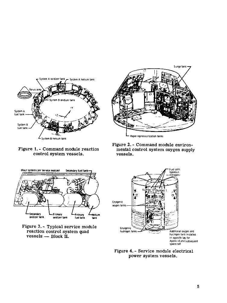
Design data and other pertinent information for Apollo spacecraft pressure ves- sels a r e presented in tables I and 11. Many of the larger or more numerous vessels have safety factors as low as 1 .5 to achieve a lightweight structure. The locations and uses of many of the vessels throughout the spacecraft a r e shown in figures 1 to 9. The assimilation of pressure vessels in the spacecraft design and the relationship to space- craft operation a r e illustrated in those figures.
The Apollo spacecraft was designed and built in Block I and Block I1 configurations for the command and service modules. Essentially, Block I vehicles did not contain all the systems necessary for docking and lunar flight and were used unmanned to qualify various Apollo subsystems. Block I1 vehicles were fully configured for manned lunar missions. For the Block I1 configurations, some minor changes were made in the pressure-vessel designs for the service propulsion system (SPS), and vessel additions were made to the SM reaction control systems (RCS). Generally, the SPS helium and propellant vessels maintained the same overall dimensions and operating s t resses , but operating pressures and wall thickness were reduced. Materials and processes re- mained the same. Two vessels were added to each SM RCS panel to provide additional RCS capacity for the Block I1 configuration. These additional vessels were of the same design as the CM RCS vessels.
Rigorous qualification tests (vibration, shock, acceleration, pressure cycling, and burst) were performed on production vessels of each type to demonstrate attainment of design requirements. The tests performed on each vessel are identified in table ID. In some cases, the qualification of Block I vessels sufficed for Block I1 configuration. Each qualification vessel was given a nondestructive test (NDT) evaluation and was ac- ceptance tested (proof pressurization and leak test) before the qualification test, as all production vessels have been tested before delivery. Subsequently, the number of pres- surizations, the fluids, the pressure levels, and the temperatures have been controlled to ensure safe test conditions and adequate flight capability. This control has been ac- complished by means of the regulation of spacecraft- systems tes ts involving vessel pressurizations through the application of fracture-mechanics criteria.
2

TABLE I. - APOLLO COMMANU AND SERVICE MODULE P-RE VESSELS
Pressure "I
wee
Prasaure. helium
Propellanl. oxldlzer
P r o W l h l . luel
P r e s u r e . ' helwm
Pr"pellan1, a oxidtier storage
Plc>pPll."l.a 1"Cl storage
Cryuecnic. liquid hydrogen
Pressure. lue l ce l l easems nilrugen
1
L a a l l o n
CM RCS
CM RCS
CM RCS
SM SPS
SM SPS
Sht SPS
SM SPS
Sht SPS
SM SPS
S M RCS
C M ECS"
C\I LCS
SI1 RCS
s h i r o
Shl RCS
S M RCS
SM EPS'
SM EPS
SM EPS
OlP"llty regulred
- 2
2
2
2
1
1
I
I
2
4
1
I
3
I
I
I
1
!
I
4
i
4
4
d
d2
3
v e s s e l dlrnens1ons. h.
DLsmeIer
9.20
12. 6
12. 6
10. 17
4 5
4 5
51
5 1
4 . 9 2
12 0
12 0
I 3 0
7 0
12 2 5
I 2 2s
26 2
8 8
21
12 6
I2 6
12 6
12.6
25 5 interior
diameter
28.24
6.0
19.901
17. 32
_ _ 153.05
153.05
152 30
152 38
9 16
l i I
12 I
16R
22
21 R
27 6
22 i
19.907
17. 32
Thlcheaa
0.102
,022
022
366
041 to , 025
, 0 4 7
054 lo ,028
054 l o .02R
135
135
1 3 5
033 t u n iR
050
050
209
102
I 06
0 2 2
022
022
022
060 -411
. 0 4 5
099
Dea1gn presure, PSI
Llrnlt - 5 m
360
360
3685
225
225
225
225
2900
4500
4500
1020
1210
40
40
fin
1725
2247
l i on
a n
248
248
248
1020
285
15W
6067
525
525
1910
300
300
300
300
5000
5985
59RT
1316
16nn
60
en
90
2450
3000
1855
360
360
480
480
1356
IW
3000
500
510
540
8540
337 5
337 5
337 5
337 5
i5w
IWO
inon
1530
!ROO
72
72
150
3370
J i 4 0
2550
372
372
540
540
1530
450
5180
__
- Normal peratlng reallure
Pel
1150
29 1
29 1
3600
186
__
I66
186
186
2550
4150
4400
900
900
32
32
40
1600
1 4 6 0
1330
185
I 85
185
185
900
! 2 5 and 21
1500
1. 5
1 5
1 5
1 5
1 5
I 5
1 5
1 5
2 5
I 55
1 55
1 5
I 5
i n
I R
2 5
1 95
I 65
1 s c
1 5
1 5
1 5
1 5
1 5
1 5
2 0
I50 and 8900
385 and 1013
185 and 1043
RIM
413
413
413
4 1 3
820 2nd i n onp
8000
moo
140 and 2RRO
767 and 3078
I 2 @
120
-150
3726
w i n and 4088
?Y2'> and Z'i411
567
603
885 and 1043
885 and 1043
1873 amblenl
775 and 812 Pmblenl
Pk00 and I O OW
3

4
I 1 1 surgetank7
System B helium tank
Figure 1. - Command module reaction control system vessels.
cnidizer tank cnidizer tank fuel tank tank
Figure 3. - Typical service module reaction control system quad vessels - Block 11.
Rapid repressurization tanks
Figure 2. - Command module environ- mental control system oxygen supply vessels.
r Fuel cells
- -.- hydrogen tank installed in opposite bay for Apollo 14 and subsequent spacecraft
Figure 4. - Service module electrical power system vessels.
5

Fuel storage tank sector 6 f
Oxidizer sump tank sector 2- /
Figure 5 . - Service module service propulsion system vessels - Block 11.
Gaseous oxygen (environmental control system) 7
Oxidizer
L F u e l lank
Helium lank lreaction control cy5leini
d x i d i i e r lank (reaction control 5yrteiril
Pitch control motor c lower jettison motor case
, Launch escape motor case y//
Figure 6. - Launch escape system vessels.
System A tankage
Hel ium pressure regulating package , [System B tankage
Figure 8. - Lunar module reaction control system vessels.
Figure 7. - Lunar module ascent stage vessels.
6

L Helium tank
Significant performance data on Apollo vessels have been generated during live propulsion-system tests at the NASA White Sands Test Facility (WSTF). Generally, a spacecraft vessel receives 10 to 12 pressure cycles during its lifetime; however, many of the flight-type vessels at the WSTF have completed, without incident, more than 350 cycles to or above operating pressure. This high degree of success is attributed largely to the close control of vessel fabri- cation and use that has been exercised on the Apollo Program and on the use of fracture-mechanics technology to predict safe vessel operation.
Figure 9. - Lunar module descent stage vessels.
TABLE 111. - SPACECRAFT PRESSURE-VESSEL QUALIFICATION
I Test performed
IVibration Tank function
Service propulsion system
Pressurization Block I
Oxidizer Block I
Fuel Block I
Sump Block I1
Gaseous nitrogen valve actuation
Shock Burst
X X
X X X X X
X X X X
X
X X
7

TABLE III. - SPACECRAFT PRESSURE-VESSEL QUALIFICATION - Continued
Tank function
CM reaction control system
Pressurization
Oxidizer
Fuel
SM reaction control system
Pressurization
Oxidizer
Fuel
Secondary vessels Block I1
Oxidizera b Fuel
Vibration
Test performed
aSame as CM reaction control system oxidizer. bSarne as CM reaction control system fuel.
8
~~~
Creep Cyclic Burst

TABLE 111. - SPACECRAFT PRESSURE-VESSEL QUALIFICATION - Continued
Tank function
CM fuel cell
Cryogenic oxygen
Cryogenic hydrogen
Gaseous nitrogen pressurization
Oxygen surge
LM reaction control systen
Pressurization
Oxidizer
Fuel
LM ascent propulsion system
Pressurization
Propellant
Vibration
Test performed
Shock Creep Cyclic Burst
X X X X
X X X X
X X X X X X
X X X --
X X
X X
X X
X X
X
9

TABLE III. - SPACECRAFT PRESSURE-VESSEL QUALIFICATION - Concluded
Tank function
LM environmental control system
Ascent stage gaseous oxygen
Descent stage gaseous oxygen
LM descent propulsion system
Pressurization ambient
Supercritical helium
Propellant
Vibration
X X
X --
X X
X X
X
Test performed
Shock Creep cyclic [ Burst
QUALITY ASSURANCE
The requirements for the quality-assurance programs of NASA contractors are delineated in NASA quality publication NPC 200-2. Applicable portions of this document were imposed by the NASA Manned Spacecraft Center (MSC) on pressure-vessel manu- facturers at the beginning of hardware fabrication to ensure adequate control of process- ing and fabrication variables and to provide for the availability of pertinent information and data concerning materials properties, deviations from requirements, Material Re- view Board (MRB) actions, and test data on each pressure vessel.
Additional Requirements
Because of problems that had been experienced from the beginning of vessel fab- rication to early 1967, a decision was made to evaluate each vessel on each Apollo spacecraft for flight worthiness before launch. Since that time, each Apollo pressure vessel has been accompanied at vehicle delivery by a data package o r "pedigree" that contains a manufacturing and processing history, including any discrepancies, and a pressurization data log. This requirement is in addition to those contained in the NASA quality publication. In this way, each vessel has been fully characterized for individual
10
evaluation of structural integrity and projected life capability. The following specific information is contained in each data package.
1. Material and process specifications (submitted one time per generic vessel unless subsequently revised)
2. Weld parameters and repair history
3. Chemical analysis of materials (including weld wire)
4. Mechanical properties verification for materials
5. Certification of acceptance testing
6. I Pressurization history (including fluids and times)
7. Fluid exposure history (other than during pressurization)
8. Discrepancy reports and reviews ~
9. Nondestructive evaluation requirements and certification
I
1 I nspection and Discrepancy Reports
Pressure vessels have been inspected by the contractor a t prescribed stages dur- ing fabrication and jointly inspected by contractor/NASA representatives at mandatory inspection points incorporated throughout vessel fabrication and during subsequent sys- tem buildup. Discrepancy reports have been written for all anomalies o r out-of- specification conditions detected during inspection o r test. These discrepancy reports have been resolved by means of MRB action by responsible contractor and NASA repre- sentatives and a r e part of each data package. Particularly serious discrepancies such as anomalies requiring detailed stress analysis or generation of empirical data for ma- terials evaluation have been resolved at higher levels but a r e reflected in MRB documentation.
Discrepancies originating at the prime contractor facilities can be classified gen- erally as scratches, dents, or fit-up irregularities. Discrepancies originating at the subcontractor (vessel manufacturer) facilities can be classified generally as machining er rors , scratches, dents, weld mismatch, weld porosity, dimensional anomalies, and, in one instance, a heat-treating e r ror . The discrepancies have been random; no trends have been observed.
In the first 13 command and service modules and nine lunar modules, 176 and 123 vessel discrepancies, respectively, were found. The number of discrepancies, which is small considering the total number of vessels (926) involved, includes many that were minor, such as superficial scratches. The number of vessel discrepancies per spacecraft is shown in figures 10 and 11.
I I
11

- Occurring at prime 0 Occurring at vessel vendor contractor
24
Spacecraft
= Occurring at prime 0 Occurring at contractor vessel vendor
111 112 113 114 Spacecraft
Figure 10. - Command and service module p r essur e-vesse 1 discrepancies.
Figure 11. - Lunar module pressure- vessel discrepancies .
Nondest r uct i ve Test i ng
The major NDT methods that have been used on Apollo vessels are ultrasonic in- spection of vessel details after the machining phases of fabrication, X-ray inspection, dye-penetrant inspection of welds, and dye-penetrant inspection of certain vessel mem- brane surfaces. In addition, magnetic-particle inspection has been used on steel ves- sels such as the lunar module descent stage gaseous oxygen vessel fabricated from DGAC steel. However, NDT has had some uncertainties that have introduced limita- tions in the use of these methods. For example, X-ray inspection can reveal surface and subsurface flaws, but flaw orientation can mask detection; whereas, penetrant in- spection detects only flaws that are open to the surface. In addition, routine inspection methods are dependent on the technique and training of the inspector and the nature of the flaw. For this reason, a precise limit could not be assigned to the minimum size of the flaw or to the population that would be detected by the inspection methods.
In the case of some metallurgical flaws in the material, such as massive embrit- tled alpha in titanium or titanium-hydride formation at welds, no satisfactory method of NDT is known. Such flaws are rare but have caused failure in pressure vessels. A neutron radiography technique has met with some success but requires development.
Because of the uncertainties involved, NDT techniques have not been used alone to guarantee the integrity of pressure vessels. However, NDT techniques have been excellent means of monitoring fabrication control and ensuring production consistency and compliance with specification requirements. In th i s respect, the application of NDT has facilitated the delivery of basically sound pressure vessels that have been con- trolled during use according to fracture-mechanics cri teria to ensure safe operation.
12

APPLl CATION OF FRACTURE-MECHAN I CS TECHNOLOGY
The heat treatment of many pressure-vessel alloys to high strength levels and use at high stresses (low safety factors) results in a potentially increased sensitivity to small f laws and various environments. Limitations in present nondestructive inspec - tion techniques could allow some relatively small flaws in the vessels to escape detec- tion. Therefore, attention had to be given to the method by which these flaws could propagate during ground testing and flight to ensure that such flaws would not result in failure of the pressure vessels. In 1967, approximately 3 years after vessel fabrica- tion was begun, the vessel proof test became a valuable inspection technique using a fracture -mechanics approach and provided a baseline for postfabrication vessel analysis.
The concepts of linear-elastic fracture mechanics (refs. 1 and 2) have been used to examine the relationship between the maximum flaw size in a pressure vessel that passes a proof test and the subsequent subcritical crack growth possible in ground-test and flight environments.
The fracture-toughness/stress- intensity approach to fracture analysis generally has been accepted as the best available means of using fracture-mechanics technology in practical problems. The fracture-toughness parameter describes the maximum flaw size that a material can tolerate without rapid fracture when stressed to a prescribed level and is the value obtained for the stress-intensity factor that results in flaw insta- bility (structural failure). This value then is called the critical stress intensity or fracture toughness. Any stress intensity at a flaw that is less than the fracture- toughness value is subcritical.
Fracture- toughness (apparent KIC) properties have been obtained for Apollo pressure-vessel materials. To investigate the compatibility of a pressure-vessel mate- rial with the fluid the vessel is intended to contain, stressed vessel-material specimens having cracks introduced of known size and shape have been exposed to the environment in question. The determination was made that, for each environment tested, an appar- ent threshold stress intensity Kth exists below which cracks in a given vessel alloy do not grow. The experimental threshold values for various Apollo vessel materials and environments are listed in table IV. Most of the threshold data in table IV have been developed for time exposures consistent with Apollo requirements. For missions longer than those of the Apollo Program, long time data must be obtained. A method for de- termining thresholds is described i n reference 3.
13
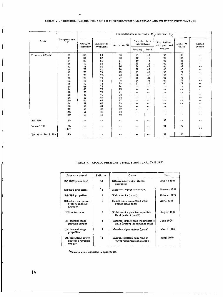
TABLE IV. - THRESHOLD VALUES FOR APOLLO PRESSURE-VESSEL MATERIALS AND SELECTED ENVIRONMENTS
Alloy
ritaniuni 6AI-4V
AM 350
Inconel 718
Titanium 5AI-2. 5Sn
remperature. " F
66 70 74 78 82 86 9 0 94 9 8
102 106 110 114 118 122 126 130 134 138 142 146 150
85
85 -297
85
Nitrogen tetroxide
82 81 80 79 78 77 76 74 73 7 1 70 68 67 65 63 52 60 58 56 55 53 51
_ _ _ _ _ _ _ _
Mononlrthy I hydrazine
88 82 8 1 81 80 80 79 78- 77 76 75 74 73 71 70 6R 67 65 64 62 60 59
_ _ _ _ _ _ - -
Threshold stress intensity Kth . percent KIC
Aerozine- 50
83 82 81 81 8 0 80 79 78 77 76 75 74 73 7 1 7 0 68 67 65 64 62 60 59
- - _ _ _ _ - _
Trichlorolri- I luoroethane -
Meld
Air. helium. nitrogen. and
oxygen
TABLE V . - APOLLO PRESSURE-VESSEL STRUCTURAL FAILURES
Pressure vessel
SM 'RCS propellant
SM/SPS propellant
SM/SPS propellant
SM/electrical power system gaseous nitrogen
LES motor case
LM descent stage gaseous oxygen
LM descent stage propellant
SM/electrical power system cryogenic oxygen
Failures
10
a2
1
1
2
1
1
a 1
Cause ~~ ~~
Nitrogen-tetroxide s t r e s s corrosion
Methanol s t r e s s corrosion
Weld cracks (proof)
Crack f rom embrittled weld repair (leak test)
Weld cracks plus incompatible fluid (water) (proof)
Material defect plus incompatiblc fluid (water) (acceptance test)
Massive alpha defect (proof)
Internal ignition resulting in overpressurization failure
Distilled water
Date
1965 to 1966
October 1966
October 1963
April 1967
August 1967
June 1966
March 1965
April 1970
Liquid oxygen
14
aVesseis were installed in spacecraft.

1 0
8
Apparent threshold K, KIC = 0 6 * K t h I w-
= 4
2
0
--.- -
(a) Log time to failure as a function (b) Flaw size as a function of of Ki/%C. membrane s t ress .
Figure 12. - Application of static fracture toughness and subcritical flaw growth to pressure-vessel analysis.
aA
15

method of analyzing pressure vessels using the modified Irwin equation from refer- ence 2, safe operation could be predicted f rom the ratio of the proof pressure to the operating pressure and from the threshold o r stress-intensity ratio required for crack growth.
Although during flight the pressure in Apollo vessels is noncyclic, the effect of cyclic f law growth during leak checks and other pressure tests of Apollo vessels also had to be considered in vessel analysis. The maximum size flaw screened by the proof test was assumed to exist, and subcritical fatigue flaw growth caused by cyclic stress was evaluated and incorporated into each analysis. For example, the cyclic flaw-growth rate for 6A1-4V titanium alloy was determined experimentally in terms of stress inten- sity as a function of the number of cycles to failure a s described in reference 4. From these data, a curve showing flaw growth rate per cycle at various Ki/KIC levels can be constructed and used in vessel analysis.
To analyze a pressure vessel, three types of basic data a r e needed.
1. The fracture toughness KIC of the material
2. The constant-stress flaw-growth threshold Kth in the environments to which the vessel wi l l be exposed
3. The rate of cyclic growth
Fracture-mechanics analyses of Apollo pressure vessels and determinations of environmental compatibility thresholds were initiated at the MSC in late 1966. The ef- fort resulted in the initiation of pressurization restrictions and environmental exposure control of all vessels by mid- 1967. The fracture-mechanics cri teria and the techniques for analyzing and controlling Apollo pressure vessels were contractually imposed on the Apollo spacecraft contractors. The implementation of these specifications established common and consistent posffabrication evaluation procedures for all Apollo spacecraft pressure vessels. Basic overall considerations and guidelines for fracture control of pressure vessels a r e presented in reference 5.
PROBLEMS ASSOCIATED WITH VESSELS USED IN APOLLO SPACECRAFT
The pressure-vessel problems experienced by the MSC and associated Apollo con- tractors a re summarized in this section. Hardware problems that resulted in struc- tural failures a r e listed in table V. Only three failures occurred on vessels installed in spacecraft: two during systems tes ts and one during the flight of Apollo 13. Gen- erally, structural failures resulted from unexpected environmental-stress-cracking effects on the vessel materials or insufficient control of materials or processes. Spe- cific problems and resolutions a r e discussed in the following paragraphs. Potential problems that were not actually experienced but that required evaluation and resolution are discussed in the last three paragraphs in this section.
16

Specific Problems
Nitrogen tetroxide incompatibility with 6A1- 4V titanium-alloy pressure vessels. - In 1965, a 6Al-4V titanium-alloy vessel containing nitrogen tetroxide (N204) under pres- sure suffered localized stress-corrosion failure. Because of known reactions between titanium and other oxidizers, extensive test programs to establish compatibility between N204 and the vessel alloy had been conducted successfully before 1965. Investigation of the cause of the failure resulted in the unexpected discovery that the alloy would undergo general stress corrosion in certain grades of N 2 0 4 (refs. 6 and 7). This discovery was particularly serious for the Apollo Program because 17 titanium vessels on each space- craft contain N204.
The chemical makeup of the N204, primarily the nitric oxide (NO) content, deter- mined whether stress corrosion would occur. Previous tests had been conducted using N204 that had a relatively high NO content. Subsequent investigations showed that s t r e s s corrosion would not occur with NO contents greater than 0.5 percent. The actual lower limit has not been defined. At the MSC, a specification was generated for N204
requiring an NO content of 0.8 f 0.2 percent to prevent recurrence of the problem. In addition, each lot of N 0 used for Apollo flights has been tested using precracked 6A1-4V titanium-alloy specimens. These data have been analyzed using fracture- mechanics principles to verify that the stress-corrosion threshold was sufficiently high to preclude environmental crack growth i n flight. The application of fracture mechanics to Apollo vessels is discussed in a separate section.
2 .4
A s a precautionary measure, each lot of fuel (Aerozine-50 and monomethyl hydra- zine) used for Apollo flights has been tested using precracked specimens to verify that the stress-corrosion thresholds are acceptable because all possible combinations and levels of impurities permitted by specification may not have existed in earlier success- ful compatibility tests.
Methanol incompatibility with 6Al-4V titanium-alloy pressure vessels. - Substi- tute fluids that simulate the specific gravity and flow characteristics of the propellants have been used to avoid the hazards associated with hypergolics when testing propulsion systems installed in spacecraft. Methanol was used to simulate Aerozine- 50 during flow tests of the SM propulsion system at operating pressures.
The first of two failures with methanol occurred on October 1, 1966, when a Block II SM vessel developed three separate leaks near the bottom girth weld while at normal operating pressure. Originally, the cause of the failure appeared to be localized stress corrosion caused by an undetected materials anomaly. Twenty-four days later, a Block I vessel containing methanol failed while pressurized to maximum operating pressure. The failure was explosive, rupturing an adjacent vessel and destroying the SM. Because the vessel was not filled to capacity, the ullage contributed to the high level of damage.
Investigation of the failures showed that pure anhydrous methanol is incompatible with the 6Al-4V titanium-alloy vessel material and results in severe stress-corrosion
17

attack (ref. 8). An SPS vessel that had successfully undergone tests with methanol was subjected to a proof pressure test and failed at 90 percent of the design proof level, showing that damage to the vessel had occurred during methanol exposure although fail- ure had not occurred. Therefore, methanol was eliminated from use in Apollo pressure vessels.
Subsequently, with initiation of fracture-mechanics evaluation techniques, ;?11 other fluids used in Apollo vessels were tested using precracked specimens. As a re- sult, trichloromonofluoromethane was restricted from use because of a relatively low stress-corrosion threshold although hardware failure had not occurred.
Failure of a service propulsion -~ ~~~ system main propellant vessel during proof test. - In 1963, during an acceptance proof test, a failure of a Block I vessel occurred that was attributable to the development of an axial fracture in the heat-affected zone of a dome- to-cylinder weld. The fracture had transgranular cleavage of a type observed in conjunction with contamination of the 6Al-4V titanium alloy. The source of the contam- ination was not definitely established. However, the contamination probably occurred during welding o r preparation for welding. The procedures and techniques were re- viewed and modified in the areas that would protect against contamination during the welding operation. Handling with clean-gloved hands was made a requirement, and a vapor-blast cleaning procedure was initiated shortly before welding to ensure clean surfaces. No subsequent occurrences of contamination were detected in SPS propellant- vessel welds.
Acceptance test failure of a lunar module descent gaseous oxygen vessel. - An LM descent stage gaseous oxygen pressure vessel made of D6AC steel failed during accept- ance testing. Failure analysis showed that the origin of the failure was a preexisting crack in the radius of the mounting boss. During acceptance testing, which consisted of pressure cycling the vessel in a water bath, the crack grew. The D6AC steel has a very low flaw-growth threshold in water. The tank manufacturer had been directed by the LM contractor not to use water as a pressurizing medium, Unfortunately, no men- tion was made of the medium in which the vessel was immersed during testing, and the use of water in this application was not discovered before the failure. Another contrib- uting discrepancy was omission of inspection. The final machined boss a reas received no detailed nondestructive testing or inspection after machining. The size of the pre- existing crack in the failed vessel was of such magnitude that the vessel would have been rejected.
Subsequently, water was replaced by a more compatible fluid, trichlorotrifluoro- ethane. All boss a reas have been dye checked and magnaflux inspected for flaws; radio- graphic inspection was instituted on all domes before welding. Subsequent rigorous environmental tes ts of sample vessels have completely qualified the design and use of the vessels on Apollo spacecraft.
Failure of launch escape system motor cases during proof tests. - In 1967, two LES motor cases made of 4335V steel failed during proof testing. These cases, and others in the same lot, had been welded with a filler wire having a higher carbon con- tent than had been used on previous lots, including the qualification cases. This unau- thorized substitution made the cases more susceptible to cracking in the weld areas and more susceptible to attack by water (the pressurizing fluid) while under stress. As a result, all cases in the affected lot were restricted from flight use. In subsequent lots,
18

oil was substituted for water as a pressurizing fluid. Quality-assurance requirements were revised to ensure that all fabrication steps and tests were accomplished in a sat- isfactory manner. Additional cases have been fabricated and tested under the new re- quirements with no recurrence of the problem.
Massive alpha inclusions in 6A1-4V titanium alloy. - An LM descent propulsion system (DPS) vessel failed during a hydrostatic acceptance proof test at 267 psig, which was 74 percent of the required 360-psig proof pressure. A metallurgical investigation showed that the failure was caused by a localized microstructure abnormality consisting of "massive" alpha-phase structure in the upper dome. A second instance of massive alpha inclusion was detected in an LM ascent propulsion system (APS) vessel dome dur- ing a hand-blending phase of fabrication because of the comparative hardness. The dome was rejected and therefore never subjected to a proof test.
Alpha inclusions of this sor t a r e rare but, if they are present, cannot be detected by the standard NDT techniques used. Reliance on the proof test to screen a gross con- dition in a finished pressure vessel has been the only practicable approach. Because the condition cannot be detected at the time of acceptance of the vessel forgings, a con- siderable dollar loss is experienced with failure of a completed vessel. Although the occurrence of massive alpha is rare, the development of a suitable NDT technique may save costs and add confidence in the future use of titanium pressure vessels.
Failure of an electrical power system gaseous nitrogen pressure vessel. - In 1967, an electrical power system (EPS) nitrogen vessel leaked in the girth weld during a pres- sure decay test. Investigation of the failure disclosed that a repaired a rea of the weld was contaminated with oxygen, resulting in an embrittled condition that was susceptible to crack initiation and growth under cyclic conditions. An evaluation of the weld repair technique and equipment showed that a high probability of oxygen contamination existed during weld repair. Investigation of other nitrogen tanks that had weld repairs verified that oxygen contamination was a problem. As a result, all EPS nitrogen vessels that had weld repairs were deleted from the Apollo Program and the repair technique was modified. Contamination was not present in unrepaired vessels, and no subsequent problems have arisen when repairs have been required.
Failure of a cryogenic oxygen vessel during the flight of Apollo 13. - In February 1970, the Apollo 13 spacecraft experienced a rapid loss of pressure in the number 2 liquid oxygen vessel, which is fabricated from Inconel 718 alloy. Essentially, the findings of the investigation of the Apollo 13 anomaly indicated that ignition occurred inside the vessel at a point of degraded Teflon wire insulation. A fire propagated rap- idly inside the vessel, increasing the temperature and pressure until the strength capa- bility of the vessel itself was exceeded and failure occurred.
The structural capability of the oxygen vessel had been demonstrated in qualifica- tion tests and on previous Apollo flights. Inconel 718 was also known to be compatible with liquid oxygen. The fault existed in internal design where electrical components, Tef lon-coated wire, and terminals exposed directly to an oxidizing environment re- sulted in a hazard under certain adverse conditions.
19

Potential Problems
Potential hydride formation in titanium-alloy-vessel welds made with unalloyed filler wire. - An explosion of a Saturn S-IVB stage during a test in March 1967 was at- tributed to the failure of a 6A1-4V titanium-alloy pressure vessel containing helium gas. The vessel had inadvertently been welded using unalloyed filler wire instead of the spec- ified 6Al-4V titanium-alloy filler wire. The failed weld had severe titanium-hydride banding that weakened the weld and ultimately resulted in vessel failure a t operating s t ress . Investigators of the failure postulated that the hydrides formed over a period of time in the region of the relatively abrupt change in hydrogen solubility between the 6Al-4V titanium alloy and the essentially unalloyed titanium weld. It was suggested that hydrogen migrated under s t ress conditions from a region of high solubility (alloy vessel material) to a region of low solubility (unalloyed weld) and precipitated as titanium hy- drides upon reaching this zone.
The latent occurrence of hydrides in the failed S-IVB vessels caused concern about the integrity of the SPS, DPS, and APS 6A1-4V titanium-alloy propellant vessels that a r e welded, by requirement, with unalloyed filler wire. A comprehensive program was un- dertaken to evaluate the Apollo welds, and it was determined that the concern about la- tent hydride formation in the Apollo welds was unwarranted.
In summary, the S-IVB helium-vessel weld w a s different geometrically and thicker (0.452 inch) than the Apollo welds (0..070 and 0.090 inch), which use unalloyed wire. In the Apollo welds (including repaired welds that have additional unalloyed filler wire), ap- parently sufficient alloying exists in the weld nugget to preclude a hydride problem.
Conversely, some Apollo titanium vessels a r e required by specification to be welded with alloy filler wire. These vessels a r e relatively thick and more closely ap- proximate the geometry and conditions of the S - N B weld. To ensure that these welds were made using alloy wire, an eddy-current technique was used that would distinguish between welds made with alloyed or unalloyed wire. No instances of wrong filler-wire use were detected.
Potential alpha-stringer structure problem in 6A1-4V titanium alloy. - The 6A1-4V titanium alloy has been used for 47 vessels in the various Apollo spacecraft propulsion systems. Therefore, a potential problem with this material was reason for concern be- cause a serious general material anomaly would have a severe negative impact on the Apollo Program.
Briefly, the metallographic structure of the alloy normally consists of a beta- phase matrix that has a dispersion of equiaxed alpha-phase "islands. " During tes ts to verify the properties of a certain lot of forgings for LM vessels, comparatively low elongation values were noted on a number of tensile test specimens taken from forging trim rings. Al l other mechanical properties were within specification limits. Metallo- graphic examination showed that many of the alpha constituents in the structure had an elongated shape and were representative of alpha platelets o r "stringers" rather than of the equiaxed alpha islands. A definite correlation was established between the low elongation and the presence of stringers.
A program was conducted to evaluate normal and alpha-stringer structure under identical test conditions. Results of the tes ts indicated that no significant differences
20

in behavior existed between the two structures except for ductility. The presence of alpha-stringer structure would not significantly affect the performance capability of the 6Al-4V titanium-alloy pressure vessels as long as elongation values were greater than the minimum specification limit of 8 percent.
Acicular o r elongated structure must not be confused with the "massive" or "low density" alpha- inclusion problem that is a threat to structural integrity.
Potential failure of lunar module descent propulsion system vessels during flight. - Cyclic-flaw-growth analysis for the LM DPS vessels showed that the maximum flaw that c&ld exist x the vessek after a normal proof test could grow during ground pressuriza- tions to a size that would give a s t r e s s intensity above propellant threshold values during flight. To provide added cyclic life, a cryogenic liquid-nitrogen proof test was insti- tuted and added to the existing ambient proof-test requirements. The cryogenic proof test has benefited by two changes in material properties that occur in the 6A1-4V tita- nium alloy with temperature. At -320" F, the alloy strength is increased, providing for a higher proof-test pressure (430 psi), and the fracture toughness of the alloy is slightly decreased, making the alloy sensitive to smaller flaws during the proof test. Therefore, the cryogenic proof test screened to a flaw size much smaller than the am- bient proof test, providing increased flaw-growth capability during vessel use. This capability eased test restrictions and made contingency pressure cycles available for retests of the DPS if required.
PRESSURE-VESSEL MANAGEMENT
During the early phases of the Apollo Program (to the end of 1966), each NASA subsystem manager had sole responsibility for the pressure vessels in his respective subsystem. Because the background and training of the subsystem managers varied, inconsistencies evolved in pressure-vessel requirements and usage.
As the Apollo Program progressed, many problems with pressure vessels re - quired specialized skills and training not possessed by the subsystem managers. included problems relating to metallurgical considerations (welding, heat treating, forging, and so forth) and service problems involving materials compatibility and safe operation analysis.
These
In 1967, a decision was made at the MSC that spacecraft pressure vessels would be treated as a unique subsystem with designated responsibility and that requirements and use cr i ter ia would be standardized. Definitions of pressure-vessel t e rms also were standardized for the Apollo Program, as presented in the appendix. An MSC technical monitor, who had the following general responsibilities, was appointed.
1. Ensuring the structural integrity of pressure vessels
2. Implementing fracture mechanics to ensure that all flight vessels will meet mission requirements (pressures, temperatures, and number of cycles of pressurization)
3. Ensuring that all fluids to which vessels a r e exposed after acceptance tests are compatible with tank material '
21

4 . Ensuring that required structural safety factors a r e maintained
5. Examining qualifications tests for adequacy
6. Assessing fabrication procedures and methods
7 . Reviewing manufacturing discrepancies and resolutions
8. Participating in the resolution of discrepancies where required
9. Establishing allowable pressure/temperature relationships for vessels during each Apollo flight
Single points of contact and responsibility for pressure vessels also were designated at the prime contractor facilities to interface with the MSC monitor, thus facilitating work- able pressure-vessel coordination and control. In addition, an MSC quality monitor was assigned to interface with the MSC technical monitor and the designated prime contractor point of contact. It w a s the responsibility of the quality monitor to ensure contractor compliance with the quality-assurance data-package requirements.
CONCLUDING REMARKS
During the Apollo Program, pressure vessels have been critical to spacecraft operation and safety. In addition to stringent material and fabrication controls, an in- crease in the level of confidence associated with pressure-vessel use w a s achieved by means of the application of fracture-mechanics cri teria to provide confidence in estab- lishing f luid/pressure/temperature limitations for pressure-vessel operations.
Pressure-vessel safety factors as low as 1 . 5 have been shown to be practical, provided proper materials, processes, and usage evaluations a r e made. Stringent material and fabrication control must be implemented to ensure consistency in metal- lurgical factors that, if varied, can significantly affect vessel performance. Material properties may be highly sensitive to variations in composition, manufacturing methods, o r service exposure. Unfortunately, metallurgical analysis of vessel failures usually provided the first evidence of material factors adversely affecting performance. The reasons for the problems and steps to preclude them were generally "after the fact. '' An analysis of the application supplemented by required testing of material before de- sign, therefore, is of major importance. Compatibility of pressurants with the vessel material under use conditions must be established, and subsequent fluid and pressure control consistent with test data is mandatory. Manufacturing methods and service environments must be evaluated thoroughly. The proper analysis and use of materials for pressure-vessel service can be achieved only by means of full coordination among systems engineers, designers, s t ress analysts, and materials specialists in meeting systems requirements. Responsibility must be delegated to ensure that all are involved.
22

RECQMMENDATI ONS
Based on Apollo spacecraft experience, the following recommendations a r e made to reduce r isk and to ensure pressure-vessel integrity on future programs.
1. Apply fracture-mechanics cri teria in pressure-vessel design.
2. Evaluate design and materials selection of components to be used inside pres- sure vessels for potential adverse conditions and effects.
3. By use of the fracture-mechanics threshold approach, establish the compati- bility of the vessel materials with each fluid which will contact the material while stressed.
4. Actively protect against the use of improper o r unauthorized materials during vessel fabrication.
5. Verify that weld repair techniques a r e sufficient to provide repaired a reas that have integrity equal to unrepaired welds.
6. Establish consistent control requirements and criteria for regulation of pressurizations.
7. Establish definite responsibility and authority in pressure-vessel activity.
8. Exercise discretion when considering the elimination, because of cost savings, of any quality-control documentation requirements or testing of pressure vessels.
Manned Spacecraft Center National Aeronautics and Space Administration
Houston, Texas, March 3, 1972 914-13-20-06-72
23

REFERENCES
1. Irwin, G. R. : Analysis of Stresses and Strains Near the End of a Crack. J. Appl. Mech., vol. 24, 1957, p. 361.
2. Tiffany, C. F. ; Masters, J. N.; and Pall, F. : Some Fracture Considerations in the Design and Analysis of Spacecraft Pressure Vessels. Presented at ASM National Metals Congress (Chicago), Oct. 1966.
3. Tiffany, C. F.; and Masters, J. N. : Investigation of the Flaw Growth Characteris- tics of 6A1-4V Titanium Used in Apollo Spacecraft Pressure Vessels. NASA CR-65586, 1967.
4. Masters, J. N. : Cyclic and Sustained Load Flaw Growth Characteristics of 6A1-4V Titanium. NASA CR-92231, 1968.
5. Tiffany, C. F. : Fracture Control of Metallic Pressure Vessels. NASA SP-8040, 1970.
6. Johnson, R. E.; Kappelt, G. F.; and Korb, L. J. : A Case History of Titanium Stress Corrosion in Nitrogen Tetroxide. Am. SOC. for Metals, 1966.
7. Kappelt, G. F.; and King, E. J. : Observations on the Stress Corrosion of the 6A1-4V Titanium Alloy in Nitrogen Tetroxide. Presented at AFMC 50th Anniver- sary Corrosion of Military and Aerospace Equipment Technical Conference (Denver), May 1967.
8. Johnston, R. L. et al. : Stress Corrosion Cracking of Ti-6Al-4V Alloy in Methanol. NASA TN D-3868, 1967.
24
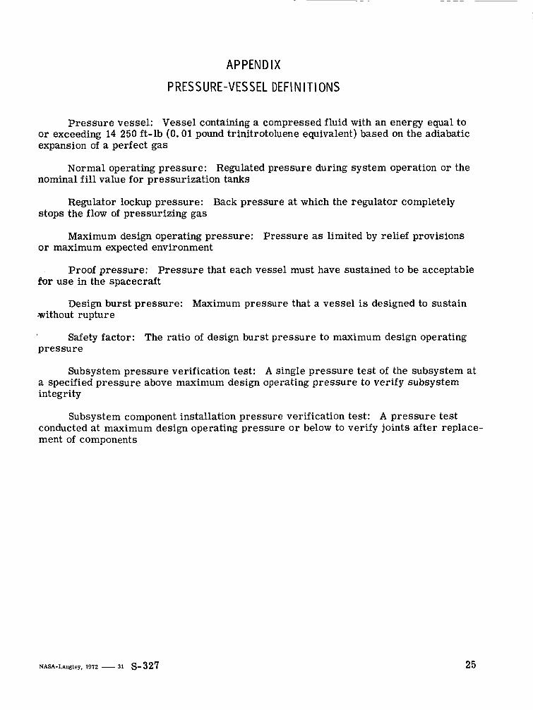
APPENDIX
PRESS URE-VES SEL DEFl N I TI ONS
Pressure vessel: Vessel containing a compressed fluid with an energy equal to or exceeding 14 250 ft-lb (0.01 pound trinitrotoluene equivalent) based on the adiabatic expansion of a perfect gas
Normal operating pressure: Regulated pressure during system operation or the nominal f i l l value for pressurization tanks
Regulator lockup pressure: Back pressure at which the regulator completely stops the flow of pressurizing gas
Maximum design operating pressure: Pressure as limited by relief provisions o r maximum expected environment
Proof pressure: Pressure that each vessel must have sustained to be acceptable for use in the spacecraft
Design burst pressure: Maximum pressure that a vessel is designed to sustain .without rupture
Safety factor: The ratio of design burst pressure to maximum design operating pressure
Subsystem pressure verification test: A single pressure test of the subsystem at a specified pressure above maximum design operating pressure to verify subsystem integrity
Subsystem component installation pressure verification test: A pressure test conducted at maximum design operating pressure o r below to verify joints after replace- ment of components
NASA-Langley, 1972 - 31 S-327 25