api standard 936.pdf
TRANSCRIPT

1
Refractory Installation Quality Control – Inspection and Testing Monolithic Refractory Linings and Materials
API STANDARD 936 THIRD EDITION, MARCH 2008 Deleted: XXXX
Deleted: X


1
Introduction
The purpose of this standard is to define minimum requirements for the installation of monolithic refractory linings and provide guidance for the establishment of quality control elements necessary to achieve the defined requirements.
1 Scope
This standard provides installation quality control procedures for monolithic refractory linings and may be used to supplement owner specifications. Materials, equipment, and personnel are qualified by the methods described, and applied refractory quality is closely monitored based on defined procedures and acceptance criteria. The responsibilities of inspection personnel who monitor and direct the quality control process are also defined.
2 Normative References
The following referenced documents are indispensable for the application of this standard. For dated references, only the edition cited applies. For undated references, the latest edition of the referenced document applies (including any addenda/errata). Additional applicable standards and other documents are listed in the bibliography that follows the Annexes. ACI1 547, Refractory Concrete (1979 edition)
ACI 547.1, Refractory Plastics and Ramming Mixes (1989 edition)
ASTM2 C 71 Standard Terminology Relating to Refractories (1988 edition)
ASTM C 113, Standard Test Method for Reheat Change of Refractory Brick (2002 edition)
ASTM C 133, Standard Test Methods for Cold Crushing Strength and Modulus of Rupture of Refractories (1997 (R2003) edition)
ASTM C 181, Standard Test Method for Workability Index of Fireclay and High-Alumina Plastic Refractories (2003 edition)
ASTM C 704, Standard Test Method for Abrasion Resistance of Refractory Materials at Room Temperature (2007 edition)
ASTM C 1054, Standard Practice for Pressing and Drying Refractory Plastic and Ramming Mix Specimens (2003 edition)
Harbison-Walker Handbook of Refractory Practices3 (first edition, 1992)
SSPC4 SP 3, Power Tool Cleaning (1982 edition, editorial revisions 2004)
SSPC SP 7/NACE No. 4, Brush-Off Blast Cleaning (2000 edition, editorial revisions 2004)
Deleted: document
Deleted: dated
Deleted: referenced
Deleted: Body of Knowledge for API 936 Refractory Personnel Certification Examination
Deleted: 1
Deleted: 2

2
3 Terms and Definitions
For the purposes of this standard, the following definitions apply.
NOTE See Annex A for a glossary of additional refractory terms that are not referenced in this standard.
3.1 abrasion resistance The ability to withstand the effects of an eroding particles for an extended period without significant loss of material or other damage.
EXAMPLE A vapor stream containing solid particles.
NOTE For refractory materials, abrasion resistance is measured in the form of erosion loss in accordance with ASTM C 704.
3.2 applicator qualification testing Pre-installation simulation of production work that is visually inspected, sampled, and tested to verify that application equipment and personnel are capable of meeting specified quality standards.
3.3 as-installed testing Testing of refractory materials sampled from the installation to confirm that they meet specified physical property standards.
3.4 biscuit A refractory piece formed within an area completely enclosed by the anchoring system.
EXAMPLE A hexmesh or flexmesh cell.
NOTE The biscuit has the shape of the enclosed area and the thickness of the lining. Biscuits are normally independent of each other except for limited connections through perforations in the anchoring system.
3.5 castable5 A combination of refractory grain and suitable bonding agent that, after the addition of a proper liquid, is installed into place to form a refractory shape or structure that becomes rigid because of a chemical action.
3.6 casting The application of wet mixed castable refractory by placing (possibly with the aid of vibration), pouring, or rodding.
3.7 cold crushing strength CCS A measure of a refractory's ability to resist failure under a compressive load as determined at room temperature after drying and/or firing.
NOTE CCS is calculated by dividing the total compressive load at failure by the specimen cross-sectional area.
Deleted: 1

3
3.8 cold wall An insulating refractory lining system greater than 2 in. (50 mm) thick with a metal shell temperature less than 500 ºF (260 ºC).
3.9 contractor The party or parties responsible for installing refractory in the owner's equipment.
3.10 curing Process of bond formation in a newly installed monolithic refractory.
NOTE For hydraulic bonded castables, curing occurs at room temperature and is facilitated by an excess of water being present to react with the cement component. For phosphate bonded plastic refractories, heating to 500°F to 700°F (260°C to 370°C) is required to form the bond.
3.11 cut-back Pre-set refractory trimmed from the lining surface via a cutting action to give the final lining thickness dimension, usually in a gunning installation.
3.12 density6 The mass of a unit volume of a substance. It is usually expressed either in grams per cubic centimeter, or in pounds per cubic foot.
3.13 dry gunning Pneumatic placement of gunning mixes where water is added at the nozzle.
NOTE See 3.21 for the definition of gunning.
3.14 dryout The initial heating of a newly installed castable lining in which heating rates and hold times are controlled to safely remove retained water without explosive spalling and to form a well distributed network of shrinkage cracks in the lining.
3.15 erosion resistant lining Refractory lining system whose purpose is to withstand the effects of an eroding material for an extended period without significant loss of material or other damage.
6 Harbison Walker Handbook of Refractory Practices 3.16 erosion service Refractory installed in locations in which erosion resistance is a determining feature of lining service life.
EXAMPLE Transfer lines, overhead lines, cyclone linings, and deflector shields of fluid solids units.
Formatted: Space After: 0 pt, Linespacing: single
Deleted: less
Deleted: .
Deleted: 3
Deleted: 9
Deleted: 5

4
3.17 firing7 The process of heating refractories to develop desired properties.
3.18 flocculating agent A chemical additive causing rapid stiffening of a fluid refractory castable.
3.19 green refractory (monolithic linings) A newly installed refractory before it is exposed to dryout or initial heating.
3.20 gun operator Individual in a dry gun operation who controls material charging, flow rate and air flow of the gunning machine. 3.21 gunning6 The application of monolithic refractories by means of air placement guns.
3.22 hammer test (of refractory lining) A subjective test of green or fired refractories in which the lining is impacted with a hammer to gauge soundness and uniformity via audible resonance. 3.23 hand packing Castable installation technique whereby refractory is placed by packing successive handfuls of material to the desired shape. Refractory is mixed at a consistency that is stiff enough for the placed refractory to hold its shape, and wet and sticky enough so that the lining formed is structurally homogenous.
3.24 hexalt anchors Individual metallic anchors used as an alternative to hexmesh in thin layer, erosion resistant linings.
EXAMPLE S-Bar, Hexcel, Curl and Tacko anchors.
3.25 hexmesh A metallic anchoring system constructed of metal strips joined together to form hexagonal shaped enclosures where erosion resistant refractory is packed after welding to the base plate steel.
NOTE Thickness is usually 3/4 in. or 1 in. (19 mm or 25 mm).
3.26 hot wall A thin refractory lining system less than 1.5 in. (38mm) thick with a metal shell temperature greater than 650 ºF (345 ºC).
3.27 hydraulic-setting (bonded) refractories6 Compositions of ground refractory materials in which some of the components react chemically with water to form a strong hydraulic bond.
Formatted: Font: Arial Bold
Formatted: Tabs: 5.49", Left
Formatted: Space After: 0 pt, Linespacing: single
Formatted: Space After: 0 pt, Linespacing: single
Deleted: 6
Deleted: F
Deleted: 3
Deleted: 7
Deleted: 8
Deleted: 9
Deleted: 4
Deleted: 0
Comment [RG1]: This requirement must be moved to the body of the document.
Deleted:
Deleted:
Deleted: hall be
Deleted: 1
Deleted: 2
Deleted: .
Deleted: .
Deleted: 3
Deleted: .
Deleted: 4
Deleted: 4

5
NOTE Hydraulic-setting refractories are commonly known as castables.
3.28 independent laboratory A refractory testing facility not affiliated with the refractory manufacturer or contractor.
3.29 inspector The party or individual whom the owner has contracted or otherwise designated to monitor refractory testing and installation work performed by the contractor and refractory material manufacturer(s).
3.30 manufacturer The party or parties blending the refractory products at the refractory manufacturing plant.
3.31 material qualification testing Pre-installation testing of refractory materials in which production lots of refractories manufactured for a specific installation are sampled and tested to confirm that they meet specified physical property requirements.
3.32 membrane curing compound A non-reactive coating applied to freshly installed cementitous materials that aids the hydration process by retarding moisture loss.
3.33 metal fiber reinforcement Metal fibers dispersed in refractory reinforcement is used to improve applied lining toughness and shrinkage crack distribution.
NOTE Metal fibers are usually made of austenitic stainless steel ¾ in. to 1 in. (19 mm to 25 mm) in length and 0.010 in. to 0.022 in. (0.3 mm to 0.6 mm) in effective diameter. They are blended into castable refractory, typically during the mixing operation, at a quantity of up to 1 volume percent (1 wt% to 4 wt%) of the refractory.
3.34 monolithic lining6 A castable lining without joints, formed of material which is rammed, cast, gunned, or sintered into place.
3.35 monolithic refractories Castable or plastic refractories applied by casting, gunning, or hand/ram packing to form monolithic lining structures of any shape.
3.36 nozzleman Individual at the point of application in a gunning operation who controls material build up via maneuvering and positioning of the outlet nozzle. In a dry gunning operation the nozzleman controls water addition via a water valve. In a wet gunning operation the nozzleman controls flocculant and possibly air via a valve. 3.37 organic fibers Low-melting-point organically based fibers such as polypropylene or polyethylene added to refractory to enhance moisture release by burning out during initial dryout, increasing the permeability by leaving tiny, interconnected, voids.
Formatted: Space After: 0 pt, Linespacing: single
Deleted: 5
Deleted: 6
Deleted: 27
Deleted: lining materials to be installed in the equipment of the owner
Deleted: 28
Deleted: 9
Deleted: 0
Deleted: .
Deleted: .
Deleted: .
Deleted: .
Deleted: 1
Deleted: 4
Deleted: 2
Deleted: 3

6
NOTE Melting points for organic fibers range from 212 ºF to 575 ºF (100 ºC to 300 ºC).
3.38 other service Refractory installed in locations where erosion resistance is not a required feature of the lining service.
3.39 owner The proprietor of equipment who has engaged one or more parties to install or repair refractory.
3.40 permanent linear change PLC A measure of a refractory's permanent linear dimensional change as a result of initial heating to a specific temperature.
NOTE A specific specimen dimension is measured at room temperature before and after heating. PLC is calculated as the percentage change in the dimension.
3.41 planetary mixer A high energy mixer with a rotating paddle on a vertical orbiting mixer shaft.
3.42 plastic refractory8 A moldable refractory material that can be extruded and has a level of workability that permits it to be pounded into place to form a monolithic structure.
3.43 potable water Water quality considered safe for human consumption.
3.44 pre-wetting (gunning) A technique used with dry gunning machines where a small quantity of water is mixed into the dry refractory before charging into the gun to reduce rebound and dust, and to improve wetting of the cement in the gunning operation.
3.45 production run The quantity of refractory having the same formulation that is prepared in an uninterrupted manufacturing operation.
3.46 pump casting Castable installation technique in which refractory is mixed with water and pumped through piping and/or hoses to the installation site, where it is poured from the outlet nozzle directly into a formed enclosure.
8 ACI 547 Refractory Concrete
3.47 ramming The use of compressive force or impact to deform a stiff refractory mix, causing it to completely fill the intended volume (e.g., a hexmesh cell) and/or fully bond or join to previously placed refractory (e.g., thick plastic linings).
Formatted: Font: 9 pt
Deleted:
Deleted: 4
Deleted: 5
Deleted: 36
Deleted: 37
Deleted: 38
Deleted: 4
Deleted: 9
Deleted: 0
Deleted: 1
Deleted: 2
Deleted: 3

7
3.48 rebound Aggregate and/or cement which bounces away from a surface against which refractory is being projected by gunning. 3.49 sample The quantity of refractory taken from a single container or installation sequence that is used to make a complete set of test specimens to determine compressive strength, erosion resistance, density, linear change, and/or any other physical properties.
NOTE Physical property test results for a sample are usually expressed as the average of two or more specimens made from the same sample.
3.50 shelf life7 Maximum time interval during which a material may be stored and remain in a usable condition. 3.51 shotboard Temporary containments used in gunning that are set up and secured to provide a firm surface on which to make perpendicular cold joints at the termination of work areas.
3.52 specimen Individual cubes, bars, plate, or other test pieces used for physical property testing.
3.53 submersion vibrators A cylindrical mechanical shaft driven device immersed into cast refractory to assist in consolidation, deairing, and promotion of flow by vibration.
3.54 supplier The party supplying the refractory and other materials to the contractor.
NOTE The supplier may (or may not) be the manufacturer.
3.55 vibration casting Castable installation technique whereby refractory is mixed with water and placed in a formed enclosure with the aid of vibration which causes the refractory to become "fluid like" and thereby flow and consolidate to the shape of the formed enclosure.
3.56 wet gunning Pneumatic placement of premixed castables (including water) where flocculating agents and placement air are added at the nozzle.
Note See 3.21 for the definition of gunning.
3.57 workability index A measure of the moldability of plastic refractories as determined in accordance with ASTM C 181. Workabilty index is commonly used to control consistency of plastic refractories during manufacture and serves as a measure of the facility with which it is rammed, gunned, or vibrated into place.
Formatted: Space After: 0 pt, Linespacing: single
Formatted: Space After: 0 pt, Linespacing: single
Deleted: 4
Deleted: 45
Deleted: against anchors
Deleted: 46
Deleted: or
Deleted: 47
Deleted: 48
Deleted: 48
Deleted: ing
Deleted: 49
Deleted: 9
Deleted: 0

8
4 Quality Control Elements
Key quality control elements related to this standard are listed in Table 1. The table lists the key elements in work chronology and identifies the objectives of each element. Also indicated are the sections of this standard in which detailed requirements for each of the elements are defined. Quality control is dependent upon proper execution of the elements in Table 1. Timely planning is vital to the success of the quality control program.
Table 1—Quality Control: Key Elements
Elements Actions Objectives
Documentation (see 5.1.1 and 5.2.1)
Owner specification and/or contractor execution plan.
Define job specific work scope.
Material qualification (see 8.2)
Testing at independent or manufacturer's laboratory. Inspector directs sampling, monitors specimen preparation and witnesses testing.
Confirm that materials manufactured for the job meet the specified physical property standards.
Applicator qualification (see 8.3)
Contractor demonstration of capabilities in simulated installation which is witnessed and inspected by the inspector.
Confirm that equipment and personnel are capable of installing qualified materials to specified standards.
Installation monitoring (see 9)
Inspector monitors contractor work and test sample preparation.
Confirm that specifications, good practice and installation procedures are followed.
As-installed testing (see 8.4)
Inspector coordinates sampling and testing of as-installed materials.
Confirm that installed materials meet specified physical property standards.
Pre-dryout inspection (see 5.3a))
Inspector performs visual/hammer test inspection of applied linings.
Confirm that installed linings meet specification standards.
Dryout monitoring (see 10)
For dryout prior to normal startup of equipment, the inspector monitors heating rates and hold times.
Confirm that agreed upon procedure is followed.
Post dryout inspection (see 5.3a))
Inspector performs visual/hammer test inspection of applied linings.
Confirm that installed linings meet specification standards.
NOTE When an independent laboratory is utilized or the contractor assumes complete accountability for as-installed testing results, inspector participation may be waived or reduced by the owner.
5 Responsibilities
5.1 Owner
5.1.1 The owner shall prepare a detailed specification. The specification shall include the following design details.
a) Lining products, thickness, method of application, and extent of coverage.
b) Anchor materials, geometry, layout and weld details. Suggested color coding for metallic anchors is provided in Annex B.
c) When used, details of metal fiber reinforcement including dimensions, concentration, type, and metallurgy.
Deleted: C
Deleted: I
Deleted: M
Deleted: I
Deleted: C
Deleted: .6
Deleted: I
Deleted: .6

9
d) Curing and dryout procedures, including constraints on dryout heating (e.g., design temperature limits and/or maximum differential temperatures that shall be maintained to avoid damaging the unit and/or components).
5.1.2 The owner shall provide quality requirements covering the following.
a) Physical property requirements to be used for qualification and installation quality control by specific product and location where the product will be utilized. These requirements shall be in accordance with manufacturer’s compliance data sheet in accordance with Annex C unless amended by prior agreement with owner.
b) Sampling frequency as applicable for the product’s intended use in either erosion service or other service (see 8.2.1.6).
c) Required lining thickness tolerances.
d) Criteria for hammer testing and the extent of cracking and surface voids permitted.
5.1.3 The owner shall approve the engineering drawings, execution plan and dryout procedure.
5.1.4 The owner shall resolve the following:
a) exceptions, substitutions, and deviations to the requirements of the execution plan, this standard, and other referenced documents;
b) conflicts between the execution plan, this standard, and other referenced documents;
c) actual or potential work deficiencies discovered and submitted by the inspector.
5.2 Contractor
5.2.1 The contractor shall prepare a detailed execution plan in accordance with this standard and the requirements of the owner's specification and quality standards. The execution plan shall be prepared, submitted for the owner’s approval, and agreed to in full before work starts. Execution details shall include:
a) designation of responsible parties;
b) designation of inspection hold points and the required advance notification to be given to the inspector;
c) surface preparation and welding procedures;
d) procedures for material qualification, material storage, applicator qualification, installation and quality control;
e) curing (including the curing compound, if any, to be used) and dryout procedures for the completed lining system.
5.2.2 Submission to the owner of all exceptions, substitutions, and deviations to the requirements of the execution plan, this standard and other referenced documents. Owner's approval shall be secured before implementation of the changes.
5.2.3 Scheduling of material qualification tests and delivery of those materials and test results to the site.
Formatted: Outline numbered +Level: 1 + Numbering Style: a, b, c,… + Start at: 1 + Alignment: Left +Aligned at: 0" + Tab after: 0.25" +Indent at: 0.25"
Formatted: Bullets and Numbering
Formatted: Outline numbered +Level: 1 + Numbering Style: a, b, c,… + Start at: 1 + Alignment: Left +Aligned at: 0" + Tab after: 0.25" +Indent at: 0.25"
Formatted: Bullets and Numbering
Formatted: Outline numbered +Level: 1 + Numbering Style: a, b, c,… + Start at: 1 + Alignment: Left +Aligned at: 0" + Tab after: 0.25" +Indent at: 0.25"
Formatted: Bullets and Numbering
Deleted: )
Deleted: standards
Deleted: 5.1.5 The owner shall establish the method of payment for testing of samples.
Deleted: o

10
5.2.4 Scheduling and execution of work to qualify all equipment and personnel required to complete installation work, including documentation and verification by the inspector.
5.2.5 Preparation and identification of all testing samples (preshipment, appicator qualification, and production/installation) and timely delivery to the testing laboratory.
5.2.6 Advance notification to the owner of the time and location where work will take place so that this information can be passed on to the inspector.
5.2.7 Execution of installation work, including preparation of as-installed samples in accordance with 8.4.
5.2.8 Provide inspector verified documentation of installation records, including:
a) product(s) being applied;
b) pallet numbers and location where applied;
c) installation crew members (designating nozzleman and gun operator when gunning);
d) mixing and/or gunning equipment utilized;
e) fiber and water percentages;
f) mixing details including time, temperature, and aging time (if gunned);
g) location and identity of samples taken for installation quality control;
h) shell temperatures;
i) weather conditions and any other unusual conditions or occurrences.
j) dryout records
5.2.9 Accountability for installed refractories meeting specified standards, including as-installed testing results as defined in 8.4.4, and lining thickness tolerance limits as defined by 5.1.2c.
5.3 Inspector
The inspector shall:
a) Ensure that material and applicator qualification test results are fully documented.
b) Monitor qualification, production work and dryout (when applicable) conducted by the manufacturer(s) and contractor to ensure compliance with job specifications and agreed-to quality practices.
c) Notify the owner and the contractor of any work deficiencies or potential deficiencies. Notification shall be made according to the job specific requirements outlined in the procedures. Notification shall take place as soon as possible, and shall occur within one working day after discovery of the deficiency.
d) The inspector shall not make engineering decisions contrary or in addition to specified requirements.
Formatted: Bullets and Numbering
Formatted: Bullets and Numbering
Formatted: Normal
Formatted: English (U.S.)
Deleted: /
Deleted: 3.
Deleted: 5.3.1
Deleted: 5.3.2
Deleted:
Deleted: 5.3.3
Deleted: 5.3.4

11
e) Conflicts between the specified execution plan and the actual installation procedures or installed refractory quality results shall be submitted to the owner for resolution.
f) Inspect and hammer test installed linings before dryout and after dryout (when possible), and report any anomalies to the owner.
g) Check and verify that accurate installation and dryout records are being documented by the contractor in accordance with 5.2.8.
h) Record all non-conformances and/or potential problems to which the inspector has alerted the contractor and owner.
5.4 Manufacturer
The manufacturer shall
a) provide a compliance data sheet in accordance with Annex C for each product,
b) provide material that meets the approved compliance data sheet,
c) provide all documentation required in 7.3.2.2, and
d) for plastic refractories, provide the minimum acceptable workability index (per ASTM C 181) for successful refractory application.
6 Inspector Qualifications
6.1 The inspector shall have no commercial affiliations with the contractor or manufacturer(s).
6.2 The inspector shall be certified in accordance with Annex D.
6.3 The inspector shall possess this standard, owner specifications, the project execution plan, and other job specific requirements outlined by the owner, contractor, and/or manufacturer. The inspector shall have working knowledge of these documents.
6.4 The inspector shall submit a resume documenting experience (including similar materials and application) to the owner for approval.
7 Materials
7.1 Physical Property Requirements
7.1.1 Refractories applied in accordance with this standard shall be sampled and tested to verify that the physical properties meet intended criteria. As defined in 5.1.2a), product specific physical property requirements shall be determined by agreement prior to material qualification. Qualification shall be based upon the sampling/testing procedures described in this standard.
7.1.2 The acceptance/rejection criteria for both material and applicator qualification testing are determined by average physical properties for each sample shall fully meeting the criteria established for that material in 5.1.2a).
Deleted: 5.3.5
Deleted: procedures/standards
Deleted: 5.3.6
Deleted: 5.3.7
Deleted: 5.3.8
Deleted: 1
Deleted: in accordance with ASTM C 181

12
7.1.3 Acceptance/rejection criteria for as-installed testing shall be based upon criteria and procedures agreed to prior to work start. The physical properties criteria of 5.1.2a) shall be extended to account for field conditions as shown in Table 3 (see 8.4.4).
7.2 Storage
7.2.1 General
Refractory materials are affected by moisture, humidity and elevated ambient temperatures. Proper storage of these materials is critical to the development of optimal physical properties. Shelf life is also affected by the ambient conditions. Storing refractory in the proper conditions will enhance shelf life.
7.2.2 Weather Protection
Refractory materials shall be stored in a weather protected area. The storage facility shall prevent moisture contact with the refractory. Storage shall be on an elevated, ventilated platform. Moisture shall be directed away from the refractory.
7.2.3 Temperature
Refractory materials shall be stored at a temperature of 40 °F to 100 °F (5 °C to 38 °C).
7.2.4 Shelf Life
Time limits for material tests (see 8.2.3) shall set the refractory shelf life requirements. If the manufacturer’s shelf life recommendations (e.g. as noted on the compliance data sheet) are more stringent, the manufacturer’s restriction shall apply.
7.2.5 Discarding Criteria
Materials that exceed the shelf life (see 7.2.4) shall be discarded. Packages with broken seals or that have become damp or wet (see 9.3)or for plastics only, refractory with a workability index below the manufacturer’s minimum required value (see 5.4d), 8.3.3.6 and 8.3.4.6) shall be subject to re-qualification or discard.
7.3 Packaging and Marking
7.3.1 General
Packaging of refractory is important to preserving the integrity of the material. Markings provide valuable information to determine the age of material, assist in establishing water content requirements and track the placement of material as defined in the quality control program provided by the contractor.
7.3.2 Regulations and Material Safety Data Sheets (MSDS)
7.3.2.1 Refractory materials shall comply with all applicable federal, state, and local codes and regulations on storage, handling, safety, and environmental requirements.
7.3.2.2 The latest issue of the refractory manufacturer's compliance data sheets, application instructions, and MSDS shall be available at the installation site and complied with during the installation of monolithic refractory linings.
7.3.3 Packaging
7.3.3.1 Hydraulic bonded castable refractories shall be packaged in sealed, moisture-proof bags.
Deleted: 8
Deleted: ,
Deleted: variation in
Deleted: 5
Deleted: 5
Deleted: track
Deleted: 1
Deleted: 1
Deleted: L

13
7.3.3.2 Chemical setting refractories shall be packaged in heat-sealed plastic to assure vapor-tight enclosure. Mechanical protection shall be provided by cardboard, rigid plastic or metal outside containers.
7.3.4 Marking
7.3.4.1 Refractory bags or containers shall be marked with the product name, batch number, and date of manufacture clearly shown.
7.3.4.2 Refractory bags or containers shall be marked with the contained refractory weight. The actual weight shall not deviate from the marked weight by more than ± 2 %.
7.3.4.3 The bag or container for cast, hand-packed or rammed mixes shall be marked with the mixing instructions.
7.3.4.4 Each pallet shall be uniquely identified by pallet number and code date.
7.4 Anchors
Selection, installation, inspection and testing of anchors shall be in accordance with the design drawings and specifications.
8 Qualification and Testing
8.1 Testing and Test Procedures
8.1.1 General
Testing shall be in strict accordance with ASTM procedures as modified below. The laboratory conducting the test procedures shall be subject to audit and approval by the owner. Quality control testing shall consist of density, cold crushing strength (CCS), permanent linear change (PLC), abrasion loss (when applicable), and workability index (plastics only). Other tests required by the owner shall be as defined in the owner’s specifications.
8.1.2 Cold Crushing Strength
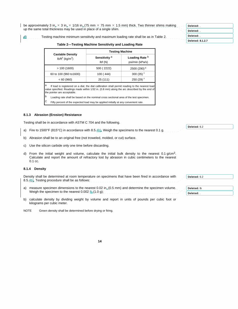
Testing shall be in accordance with ASTM C 133, and the following:
a) Cube loading surfaces shall be parallel to within a tolerance of ± 1/32 in. (± 0.8 mm) and 90 degrees ± 1 degree, whether cast or gunned.
b) Cold crushing strength shall be determined on samples that have been fired to 1500ºF (815ºC) in accordance with 8.5.4b).
c) The loading head of the test machine shall have a spherical bearing block.
d) For cast or hand packed specimens, the load shall be applied to either pair of faces cast against the side of the molds. For specimens cut from a larger cast panel, an open face shall not be used for the top or bottom (i.e., load application faces) during the test. For gunned specimens, load shall be applied perpendicular to the gunning direction, in other words, on cut faces perpendicular to the face of the panel.
e) Bedding material shall be non-corrugated cardboard shims, placed between the test specimen and the loading surfaces. New shims shall be used for each test cube. Shim dimensions shall
Formatted: Bullets and Numbering
Deleted: 7.3.3.3 Packages with broken seals shall be subject to requalification. In addition, plastics with variation in workability shall be subject to requalification (see 8.3.3.5 and 8.3.4.5).
Deleted: ,
Deleted: shelf life,
Deleted: target water content and
Deleted: 8.1.2.1
Deleted: 8.1.2.2 through 8.1.2.7.
Deleted: 8.1.2.2
Deleted: .
Deleted: 6.2
Deleted: 8.1.2.3
Deleted: 8.1.2.4
Deleted: 8.1.2.5
Deleted: 8.1.2.6
14
be approximately 3 in. 3 in. 1/16 in. (75 mm 75 mm 1.5 mm) thick. Two thinner shims making up the same total thickness may be used in place of a single shim.
d) Testing machine minimum sensitivity and maximum loading rate shall be as in Table 2.
Table 2—Testing Machine Sensitivity and Loading Rate
Testing Machine Castable Density
lb/ft3 (kg/m3) Sensitivity a lbf (N)
Loading Rate b
psi/min (kPa/s)
> 100 (1600) 500 ( 2222) 2500 (290) c
60 to 100 (960 to1600) 100 ( 444) 300 (35) c
< 60 (960) 25 (111) 250 (29) c
a If load is registered on a dial, the dial calibration shall permit reading to the nearest load value specified. Readings made within 1/32 in. (0.8 mm) along the arc described by the end of the pointer are acceptable. b Loading rate shall be based on the nominal cross sectional area of the test specimen. C Fifty percent of the expected load may be applied initially at any convenient rate.
8.1.3 Abrasion (Erosion) Resistance
Testing shall be in accordance with ASTM C 704 and the following.
a) Fire to 1500°F (815°C) in accordance with 8.5.4b). Weigh the specimens to the nearest 0.1 g.
b) Abrasion shall be to an original free (not troweled, molded, or cut) surface.
c) Use the silicon carbide only one time before discarding.
d) From the initial weight and volume, calculate the initial bulk density to the nearest 0.1 g/cm3. Calculate and report the amount of refractory lost by abrasion in cubic centimeters to the nearest 0.1 cc.
8.1.4 Density
Density shall be determined at room temperature on specimens that have been fired in accordance with 8.5.4b). Testing procedure shall be as follows:
a) measure specimen dimensions to the nearest 0.02 in. (0.5 mm) and determine the specimen volume. Weigh the specimen to the nearest 0.002 lb (1.0 g);
b) calculate density by dividing weight by volume and report in units of pounds per cubic foot or kilograms per cubic meter.
NOTE Green density shall be determined before drying or firing.
Deleted: .
Deleted: .
Deleted: .
Deleted: 8.1.2.7
Deleted: 6.2
Deleted: 6.2
Deleted: lb
Deleted: .

15
8.1.5 Permanent Linear Change
8.1.5.1 General
Testing shall be in accordance with ASTM C 113 and the following:
a) The length of each test specimen shall be measured to the nearest 0.001 in. (0.025 mm) along the 9 in. (230 mm) dimension at each of the four edges of the specimen.
b) At room temperature, determine the green refractory dimension by measuring the length of the specimen. For heat-setting plastic refractories the green dimension shall be determined from the form dimensions. Oven dry the specimens in accordance with 8.5.4a).
c) After cooling to room temperature, measure the dried length of the specimen and then fire in accordance with 8.5.4b).
d) After cooling to room temperature, measure the fired length of specimen.
8.1.5.2 Green-to-dried and Dried-to-fired Permanent Linear Change
8.1.5.2.1 General
Determine the green-to-dried and dried-to-fired permanent linear change as follows. Report the permanent linear change as an average percent shrinkage in length for each specimen to ± 0.05%.
8.1.5.2.2 Green-to-dried
Determine the green-to-dried length change of each of the four edges of the specimen. Divide each change by the green length of that edge. Average the four values to obtain the green to dried permanent linear change of the specimen.
8.1.5.2.3 Dried-to-fired
Determine the dried-to-fired length change of each of the four edges of the specimen. Divide each change by the dried length of that edge. Average the four values to obtain the dried to fired permanent linear change of the specimen.
8.1.6 Workability Index
Testing shall be in accordance with ASTM C 181 testing 5 specimens per sample.
8.2 Pre-shipment Refractory Qualification Testing
8.2.1 General
8.2.1.1 Refractories to be installed by gunning, casting, or hand/ram packing shall be tested to ensure that they comply with specified physical property requirements as described in 5.1.2a). Tested physical properties shall be density, permanent linear change (PLC), cold crushing strength (CCS) or abrasion resistance (for abrasion resistant refractory), and workability index (for plastic refractory), in accordance with 8.1 and 8.5.
8.2.1.2 Subject to owner’s approval, the contractor shall arrange for testing at either an independent laboratory or the manufacturer’s plant, and direct the work to assure that mixing techniques, water quality and content, ambient temperatures, mix temperatures, etc, represent those needed for production
Deleted: 8.1.5.1.1
Deleted: 8.1.5.1.2 through 8.1.5.2.3.
Deleted: .
Deleted: 8.1.5.1.2
Deleted: .
Deleted: 8.1.5.1.3
Deleted: 6.1
Deleted: 6.2
Deleted: 8.1.5.1.4
Deleted: 8.1.5.1.5
Deleted: and shall be conducted seven days after manufacture
Deleted: determined
Deleted: accordance with

16
installation. The testing party is responsible for conducting sampling, specimen preparation, testing, and documentation of results.
8.2.1.3 For plastic refractories, the manufacturer shall provide the actual workability index determined seven days after manufacture in accordance with 8.1.6 and the minimum acceptable workability index for suitable installation of each plastic refractory supplied.
8.2.1.4 Metallic components (e.g., anchors) shall be certified according to owner’s criteria.
8.2.1.5 The contractor shall inform the owner of testing arrangements and timing so that the owner may notify the inspector to witness or spot check the testing. When engaged as a witness, the inspector shall select the container to be tested and observe all sampling, specimen preparation, and testing. In cases where an independent laboratory is utilized or the contractor assumes complete accountability for as-installed testing results, inspector participation may be waived or reduced by the owner.
8.2.1.6 Based upon the service designation, minimum testing frequency shall be as follows:
⎯ erosion service–one sample per pallet or partial pallet from each production run;
⎯ other service–one sample per three pallets or less from each production run.
When the refractory is packaged in bags or other similar container, the sampled bag shall be randomly selected.
8.2.2 Forming of Refractory Test Specimens
8.2.2.1 As directed by the contractor and subject to approval by the owner, the entire selected container of refractory shall be mixed and test specimens formed using metal or plastic forms of the required specimen dimensions. Alternatively, samples may be made to larger dimensions and then cut to the required dimensions after 24-hour cure. See 8.5 for details of specimen preparation.
Note: When the refractory is packaged in supersacks or other similar bulk containers, a representitve sample of appropriate size shall be collected from each container at the time of packaging of the production run.
8.2.2.2 For cast installations, refractory shall be cast in the same manner as the installation. For vibration cast installations, vibration shall be used in the forming of the test specimens.
8.2.2.3 For pump cast installations, refractory shall be poured into forms.
8.2.2.4 For hand packed installations, refractory shall be hand packed.
8.2.2.5 For gunned installations, refractory shall be gunned to produce a large panel. Specimens shall be cut from the central portion of the panel (i.e., away from the edges). Alternatively, specimens may be cast or hand packed subject to prior submission and owner approval of a suitable, product specific correlation to gunned properties supplied by the manufacturer.
8.2.2.6 Plastic and other ramming refractories shall be formed using a mallet or handheld pneumatic rammer. Specimen formation using a pneumatic or ramming press, as described by ASTM C 1054, is not permitted.
8.2.3 Application Period
Refractory shall be applied within four months of the initial qualification tests. If the initial qualification period is exceeded, the refractory batch may be requalified in accordance with 8.2.1 and 8.2.2.
Formatted: Font: 9 pt
Formatted: Indent: Left: 0",Hanging: 1.53"
Deleted: 5
Deleted: and
Deleted:

17
Requalification permits usage for an additional three months after each requalification test. Refractory older than the manufacturer's recommended shelf life shall not be used.
8.2.4 Re-testing
In the event a sample fails to meet specified requirements, it may be retested once. The retest shall be conducted using a new sample representing the same pallet(s) of the same batch of refractory as the failed sample. Use the same testing facility, testing procedure, inspector, and inspection methods. A different facility may be used, subject to the owner's approval. If the retest is unsuccessful, the refractory represented by the sample(s) shall not be used.
8.3 Qualification of Installation Procedure and Crew/Installers
Prior to installation, the contractor shall demonstrate that the specified quality standards will be met using the material qualified for the job, including metal and organic fibers as applicable, and the installation method, equipment and personnel to be utilized for the installation work. This shall be done by simulating the installation and sampling and testing the applied materials as follows:
8.3.1 Pneumatic Gunning
8.3.1.1 A test panel shall be prepared by each nozzleman/gun operator team for each refractory being installed. The panel shall be inspected, sampled, and tested prior to commencing the actual installation. Preparation and examination shall be in accordance with 8.3.1.2 through 8.3.1.7.
8.3.1.2 A test panel measuring 24 in. 24 in. (600 mm 600 mm) shall be fabricated. The panel thickness, anchors and anchor pattern shall be in accordance with the actual installation job.
8.3.1.3 The test panel forms shall be constructed with a removable back and sides to permit visual inspection of the installed castable. The method of anchor attachment shall permit removal of the forms without damage to the refractory or the anchors (e.g., use a bolt through the form). Interior surfaces of the forms shall be coated with a manufacturer approved parting agent to facilitate removal from the refractory.
8.3.1.4 The test panel shall be inclined 45 degrees above the horizontal and supported on a frame so that the panel's midpoint is approximately 6 ft (1.9 m) above grade. The nozzleman/gun operator team shall demonstrate their abilities by gunning the test panel in this inclined position.
8.3.1.5 At least 24 hours after completion of the panel, remove the forms and inspect the panel for voids, laminations, non-uniformities, entrapped rebound, or other flaws. The panel shall then be sectioned or broken and the exposed surfaces inspected for voids, laminations, non-uniformities, and rebound entrapment.
8.3.1.6 Test specimens (number and type in accordance with 8.5) shall be cut from the center of each panel and tested in accordance with 8.1 for compliance to 5.1.2a) physical property requirements for density, permanent linear change, and cold crushing strength or, where applicable, abrasion resistance (see Table 4). Alternatively, with the owner’s approval, full testing may be waived and measurements of the panel dimensions and weight used to determine the green density, which is then compared to a previously approved manufacturer supplied value. Panel dimensions and weight shall be determined before the panel is sectioned or broken.
8.3.1.7 Satisfactory examination and test results in accordance with 8.3.1.5 and 8.3.1.6, shall serve to qualify the mixing and installation procedures and the nozzleman/gun operator teams. The nozzleman and gun operator shall not gun refractory materials until they are qualified.
Deleted: work
Deleted: .
Deleted: .
Deleted: standards

18
8.3.2 Casting
8.3.2.1 A mock-up shall be prepared by each applicator, for each mixing/installation procedure, and for each refractory being installed. The mock-up shall simulate the most difficult piece of the installation work for which the subject refractory and mixing/installation procedure will be used, or shall be of the size/shape agreed to in the documentation phase (see 5.2.1). The mock-up shall be inspected, sampled and tested prior to commencing the actual installation. Preparation and examination shall be in accordance with 8.3.2.2 through 8.3.2.9.
8.3.2.2 The mock-up shall simulate forming and general installation procedures, including mixing, handling/delivery to the lining cavity and associated quality control requirements. Installation of refractory shall be in the same orientation to be used for the actual installation and shall simulate installation obstacles (e.g., around nozzle protrusions and beneath overhangs), and fit-up tolerances if work involves lining of sections to be fit-up at a later date.
8.3.2.3 The refractory thickness, anchors, and anchor pattern shall be in accordance with the actual installation job.
8.3.2.4 For vibration cast installations, the mock-up shall demonstrate the adequacy of the vibration method, equipment and means of vibrator attachment.
8.3.2.5 For pouring and pump cast installations, only vibration that will be used in the actual installation shall be allowed in the mock-up.
8.3.2.6 The forms shall be constructed to permit removal for visual inspection of the refractory. The method of anchor attachment shall permit removal of the forms without damage to the anchors or the refractory. Interior surfaces of the forms shall be coated with a manufacturer approved release agent to facilitate removal from the applied refractory.
8.3.2.7 Test specimens (number, type, and preparation in accordance with 8.5) shall be prepared using material sampled from the mixes prepared for casting the mock-up. Specimens shall be formed in molds using the same level of agitation as the mock-up. Specimens shall be tested in accordance with 8.1 for compliance to 5.1.2a) physical property requirements for density, permanent linear change, and cold crushing strength or, where applicable, abrasion resistance (See Table 4).
8.3.2.8 Refractory cast in the mock-up shall be cured for 12 hours minimum prior to stripping the forms. Remove the forms and visually inspect the refractory. The applied lining shall be homogeneous and free of voids or segregations and shall meet specified tolerances.
8.3.2.9 Satisfactory examination and test results in accordance with 8.3.2.7 and 8.3.2.8, shall serve to qualify the applicators and the mixing and installation procedures as well as the mix water levels. The applicator(s) shall not cast refractory linings until they are qualified.
8.3.3 Thin Layer Abrasion (Erosion) Resistant Refractories
8.3.3.1 A test panel 12 in. 12 in. ¾ in. or 1 in. (300 mm 300 mm 19 mm or 25 mm), shall be packed by each applicator for each anchoring system and refractory being installed by the applicator. The test panel shall be inspected, sampled, and tested prior to commencing the actual installation. Preparation and examination shall be in accordance with 8.3.3.2 through 8.3.3.7.
8.3.3.2 Panel thickness shall be the same as the lining to be installed. Mixing and application techniques (for example, pneumatic ramming, hand packing), orientation (sidewall or overhead), etc, shall be in accordance with the actual installation job.
Deleted: work
Deleted: .
Deleted: .
Deleted: .
Deleted: .
Deleted: 20
Deleted: ,

19
8.3.3.3 The hexmesh or hexalt anchoring system(s) (as used for the actual installation) shall be attached to a backing plate in such a manner that the backing plate may be removed without damaging the refractory or the anchoring system. For hexalt systems, perimeter forms shall also be used to contain the refractory. The backing plate (and forms, if required) shall be coated with a manufacturer approved release agent to facilitate removal from the applied refractory.
8.3.3.4 Examination of the panel may be performed immediately after ramming, or within 24 hours, as directed by the owner. Remove the backing plate and examine the panel from the backside. The lining shall be free of voids, incomplete filling of the anchoring system and inadequate compaction of the refractory.
8.3.3.5 Test specimens shall be prepared using materials sampled from the mixes applied. Specimens shall be formed in molds (See 8.5), using the same placement method as the test panel. Specimens shall be tested in accordance with 8.1 for density, permanent linear change, and abrasion resistance. The results shall be in compliance with 5.1.2a).
8.3.3.6 For each batch of plastic refractories the workability index shall be determined and shall exceed the minimum acceptable value for installation (see 5.4d and 8.1.6).
8.3.3.7 Satisfactory examination and test results in accordance with 8.3.3.4 through 8.3.3.6, shall serve to qualify the applicator(s) and the mixing and installation procedures, as well as the mix water levels. The applicator(s) shall not apply refractory linings until they are qualified.
8.3.4 Thick Layer Plastic Installations (Greater than 2 in.)
8.3.4.1 A test panel shall be pneumatically ram packed by each applicator and for each refractory being installed. The test panel shall be inspected, sampled, and tested prior to commencing the actual installation. Preparation and examination shall be in accordance with 8.3.4.2 through 8.3.4.8.
8.3.4.2 The test panel shall be 24 in. x 12 in. (600 mm x 300 mm) with an applied lining thickness, anchors and anchor pattern in accordance with the actual installation job.
8.3.4.3 The test panel for shall be constructed with removable back and sides to permit visual inspection of the installed refractory. Anchors shall be attached to the form in a manner that permits removal of the backing plate without damage to the refractory or the anchoring system. Interior surfaces of the backing plate and forms shall be coated with a manufacturer approved parting agent to facilitate removal from the applied refractory.
8.3.4.4 Test panel refractory shall be installed by pneumatic ramming in a manner and orientation (e.g., sidewall or overhead) simulating the actual installation.
8.3.4.5 After refractory installation is completed, the test panel forms and backing plate shall be removed immediately and the refractory examined from the backside. The refractory shall be free of inadequate consolidation and voids. The sample shall be sectioned and examined to confirm that the refractory plastic is free of inadequate consolidation and/or voids around the anchors.
8.3.4.6 For plastic refractories the workability index shall be determined and shall exceed the minimum acceptable value for installation (see 5.4d and 8.1.6).
8.3.4.7 Except as noted in 8.3.4.6, test specimens and testing are not required.
8.3.4.8 Satisfactory results in accordance with 8.3.4.6 shall serve to qualify the equipment, techniques, and applicator. The applicator(s) shall not ram pack refractory materials until they are qualified.
Deleted: compared to the value determined by the manufacturer and
Deleted: .4
Deleted: and
Deleted: 5
Deleted: .
Deleted: .
Deleted: .
Deleted: S
Deleted: .4
Deleted: and compared to the value determined by the manufacturer

20
8.4 Production (As-Installed) Refractory Sampling and Testing
8.4.1 Gunning
8.4.1.1 A minimum of one sample of applied refractory shall be gunned by each gunning crew per material per shift using a "wire mesh basket". At least one sample shall be prepared for each lined item.
8.4.1.2 The basket shall be approximately 12 in. 12 in. (300 mm 300 mm) and at least 4 in. (100 mm) deep but no greater than the installed refractory thickness. The basket shall be constructed of wire mesh with ½ in. (13 mm) square openings.
8.4.1.3 The basket shall be supported on the wall where the lining application is proceeding, filled, and immediately removed. All loose refractory or rebound material shall be removed from the area where the basket was placed during sample preparation. Production samples shall remain in the same environment as actual production installation for the first 24 hours.
8.4.1.4 The required test specimens (number and preparation in accordance with 8.5) shall be diamond saw-cut from the refractory applied in the basket. Testing shall be in accordance with 8.1 for density, permanent linear change, and cold crushing strength or, where applicable, abrasion resistance.
8.4.1.5 Alternatively, panels with enclosed sides may be used in place of the wire baskets if the panel dimensions are at least 18 in. 18 in. 4 in. (450 mm 450 mm 100 mm), but no deeper than the installed refractory. Test specimens shall be cut from the center of the panels to avoid inclusion of rebound possibly trapped along the sides of the panels.
8.4.2 Casting
8.4.2.1 A minimum of one sample of the material being installed shall be cast by each mixing crew per material per shift. At least one sample shall be prepared for each lined item.
8.4.2.2 Test specimens may be formed by casting directly into molds or by casting into larger forms and diamond saw cutting to the required specimen dimensions after curing. Production samples shall remain in the same environment as actual production installation for the first 24 hours.
8.4.2.3 Vibration shall be used in casting of samples as applicable to simulate installation work.
8.4.2.4 The specimen requirements and preparation shall be in accordance with 8.5. Testing shall be in accordance with 8.1 for density, permanent linear change, and cold crushing strength or, where applicable, abrasion resistance.
8.4.3 Plastics and Thin Layer Erosion Resistant Linings
8.4.3.1 A minimum of one sample shall be packed by each applicator per material per shift. At least one sample shall be prepared for each lined item.
8.4.3.2 Test specimens (abrasion plates and linear change bars) shall be formed directly from the refractory being installed using the ramming technique used for the installation.
8.4.3.3 The specimen requirements and preparation shall be in accordance with 8.5 and testing shall be in accordance with 8.1.
8.4.4 Acceptance/Rejection Criteria
8.4.4.1 The average physical properties of each sample of the as-installed refractory shall meet the criteria defined in Table 3. Table 3 describes modifications to the evaluation criteria defined in 5.1.2a).
Deleted: .
Deleted: .
Deleted: .
Deleted: .
Deleted: between anchors
Deleted: 8.1 and
Deleted: .
Deleted: .
Deleted: .
Deleted: in accordance with
Deleted: in accordance with
Deleted: 8.1 and
Deleted: and
Deleted: t
Deleted: 8.1 and
Deleted: .1

21
8.4.4.2 Inspector verified records shall be kept by the contractor to identify the samples and the areas of the installed lining that they represent.
8.4.4.3 Failure to meet the criteria described in Table 3 shall be cause for rejection of the area of the refractory lining that the sample represents.
8.4.4.4 In the event of disagreement over the installed refractory quality, core samples may be taken from the questionable area of the applied lining and retested using the same test procedure and evaluation criteria. If the re-test is unsuccessful, the area of the lining represented by the sample shall be replaced.
8.4.4.5 The contractor shall prepare records identifying and locating all areas of rejected and replaced lining (e.g., a map), the reason for the rejection, the means of repair, and the refractory used.
Table 3—Physical Properties and Acceptable Results for Testing of As-Installed Refractories
Range of Acceptable Results a
Physical Property Minimum b Maximum b
Abrasion loss None 120%
Cold crushing strength 80% None
Density -5 lb/ft3 (-80 kg/m3) +5 lb/ft3 (+80 kg/m3)
Permanent linear change Zero c 120%
a Average of all specimen test results per sample. The minimum and maximum values are based upon the physical property value(s) listed on the manufacturer’s compliance data sheet or other value in accordance with 5.1.2a). b When the manufacturer’s compliance data sheet indicates a range for the physical property, the applicable limits shall apply to the upper and lower values of the compliance data sheet range. C Zero means 0.00% shrinkage. Products that expand shall not be used.
8.5 Test Specimen Preparation
8.5.1 Based on the use designation determined in accordance with 5.1.2b), the minimum number of refractory specimens for each sample shall be in accordance with Table 4.
8.5.2 The specimens shall be cured in accordance with 9.13.
8.5.2.1 Hydraulic bonded castable refractories shall be cured for a minimum of 24 hours after placement. During this period the exposed surfaces of the refractory shall be covered or sealed with an impermeable coating or material.
8.5.2.2 Air-setting, phosphate bonded castable refractories shall be air cured, uncovered, for a minimum of 24 hours after forming. During this period, the refractory shall be protected from moisture.
8.5.2.3 Heat-setting, plastic refractories shall be allowed to air dry for a minimum of 24 hours followed by oven drying (see 8.5.4a)) in a form suitable for drying temperatures.
Deleted: .1
Deleted: .2
Deleted: 3
Deleted: .
Deleted: 4
Deleted: 5
22
8.5.3 Once refractory specimens have been fully cured, they shall be removed from the forms, and/or cut to required dimensions. The specimens shall be marked for identification with temperature resistant paint (to prevent burn-off during firing).
Table 4—Required Number of Test Specimens Per Sample
Type of Test Number of Specimens Size of Specimens
Abrasion resistance 2 4½ in. 4½ in. 1 in. (114 mm x 114mm x 25 mm)
Permanent linear change 1 2 in. 2 in. 9 in. (50 mm 50 mm 230 mm)
For erosion service
Density — Use abrasion plates or linear change bars (before their targeted test).
Cold crushing strength 3 2 in. 2 in. 2 in. (50 mm x 50 mm x 50 mm)
Permanent linear change 1 2 in. 2 in. 9 in. (50 mm 50 mm 230 mm)
For other service
Density — Use crushing cubes or linear change bars (before their targeted test).
8.5.4 Specimens shall be dried and fired as required by the testing procedure (see 8.1). Oven drying and firing shall be as follows.
a) Oven dry: hold for 12 hours minimum at 220°F to 230°F (104°C to 110°C) in a forced air, convection dryer. Heating to this level shall be in accordance with manufacturer's recommendations. Heat setting plastics shall be oven dried in the forms.
b) Oven fire: heat at 300°F/h (170°C/h) maximum to 1500°F (815°C), hold for five hours at 1500°F (815°C); cool at 500°F/h (280°C/h) maximum to ambient. Remove heat setting plastics from the molds after oven drying and before oven firing.
9 Installation/Execution
9.1 Surface Preparation
9.1.1 Immediately before refractory installation, all surfaces to be lined shall be cleaned to meet SSPC SP-7/NACE No. 4 standards for grit blasting if rust, weld slag, oil, dirt, or other foreign materials are present on the surface to be lined.
9.1.2 If grit blast cleaning is required, anchor leg coverings (if present) shall be removed before the grit blast cleaning. After grit blast cleaning, the surfaces to be lined shall be vacuum cleaned to remove all debris and new anchor leg coverings shall be installed. Water shall not be used for washing unless it contains a suitable inhibitor.
9.1.3 Surface cleaning in accordance with SSPC SP-3 shall be acceptable only for limited areas such as spot grinding for repairs.
Deleted: 6
Deleted:
Deleted:
Deleted:
Deleted: Use of

23
9.2 Water Quality
Water used for mixing in the refractory shall be potable. The chloride content of the water shall not exceed 200 ppm. When refractory is installed on stainless steel surfaces the chloride content shall not exceed 50 ppm.
Note The 50 ppm limit does not apply when the stainless steel is limited to the anchoring system or metal reinforcing fibers.
9.3 Water-Contaminated Refractory
9.3.1 Containers of refractory exhibiting evidence of water contamination shall be discarded.
9.3.2 Any individual container of refractory material containing hard lumps (i.e., cannot be easily broken by hand) shall be discarded.
9.4 Preparation for Lining Installation
9.4.1 Timing
9.4.1.1 Refractory installation shall not begin until completion of welding, postweld heat treatment, and pressure testing.
9.4.1.2 If the refractory installation must take place before pressure testing, all pressure retaining weld seams shall remain unlined, i.e., exposed to the testing medium.
9.4.2 Lining Penetrations
Structural members, nozzle extensions, and other items within the limits of the lining shall be wrapped with 1/8 in. (3 mm) thickness of a nonabsorbent material to prevent moisture absorption from, or bonding to, the refractory lining. The wrapping shall be taped smoothly into place.
9.4.3 Openings
9.4.3.1 Openings shall be closed by means of sealed wood or metal-jacketed plugs, slightly tapered (smaller toward the shell), and of such dimensions to fit snuggly into the openings.
9.4.3.2 Surfaces of the plugs shall be lightly coated with a manufacturer approved release agent or covered with plastic to prevent bonding to the refractory.
9.4.3.3 Plugs shall not be removed from the openings or disturbed until at least 24 hours after the refractory installation.
9.4.4 Obstructions
Obstructions (e.g., scaffolding) that could interfere with the satisfactory and continuous application of the refractory lining shall be avoided.
9.4.5 Nozzle Necks
9.4.5.1 Insulating refractory in the nozzle neck shall be cast or hand packed to within 1 in. (25 mm) of the inside of the shell or head to which it is attached. The remaining 1 in. (25 mm) shall be installed monolithically with the shell lining.
Deleted: Refractory or pallets
Deleted: retested in accordance with this standard before use, regardless of the results of earlier prequalification (or re-qualification) testing.
Deleted: i
Deleted: .
Deleted: .

24
9.4.5.2 Voids or spaces to be packed with ceramic fiber blanket insulation (e.g., annular space in nozzles equipped with inner sleeves) shall be completed before the installation of refractory. Nozzles shall be packed to a point flush with the inside face of the shell. After nozzle packing, the ceramic fiber density shall be at least 8 lb/ft3 (64 kg/m3). Ceramic fiber blanket insulation shall be used only where specifically shown on the approved drawings.
9.4.6 Anchor Preparation
9.4.6.1 Anchors shall be cleaned of spatter and foreign materials before refractory is installed.
9.4.6.2 For multilayer linings, anchors for the hot-face layer shall be protected and free of all backup refractory and foreign material before application of the hot-face layer.
9.4.6.3 If anchor leg coverings are required, placement of the coverings shall be confirmed immediately before refractory placement.
9.4.7 Equipment Cleaning
9.4.7.1 Mixers, guns, conveyors, hoses, and all other equipment shall be thoroughly cleaned before use.
9.4.7.2 Equipment shall be cleaned at each material change, shift change, and more often if buildup of castable takes place.
9.4.7.3 Cleaning is required between each mix of phosphate-bonded refractory.
9.4.7.4 For non-phosphate bonded refractories, the cleaning interval shall be such as to prevent buildup of refractory materials on the mixer internals (including the drum). For low-moisture (low-cement) mixes and other refractories sensitive to water content, excess water shall be removed after each batch.
9.4.7.5 All tools used in mixing, transporting, and applying the refractory lining shall be cleaned after each batch and kept free of all deleterious materials.
9.4.8 Site
The work area shall be kept clean and protected to ensure that lining installation can proceed in an orderly manner without incorporating dirt, debris, rain, or other deleterious material into the lining.
9.5 Application Temperature
9.5.1 The temperature of the air and shell at the installation site shall be between 50°F and 90°F (10°C and 32°C) during refractory installation and for 24 hours thereafter. Shading and enclosure shall be used to protect against extremes in temperature, sun exposure, and weather (e.g., wind and rain).
9.5.2 For cold weather conditions, heating and/or external insulation may be used to maintain temperatures above the minimum requirement.
9.5.3 For hot weather conditions, shading, water spraying the unlined surface and/or air conditioning may be used to maintain temperatures below the maximum requirement.
9.5.4 Temperature limits for refractory and mix water shall be in accordance with the manufacturer's requirements. In the absence of manufacturer's mix temperature limits, mix temperature shall be between 60°F and 80°F (15°C and 27°C).
Deleted: If specifically shown on the approved drawings, any v
Deleted: thoroughly

25
9.6 Gunning
9.6.1 Dry Gunning
9.6.1.1 Pre-wet the refractory by mixing with water prior to charging into the gun. Pre-wetting reduces dusting and segregation and helps avoid plugging in the feed hose. Optimum water addition, mixing time, and aging of the pre-wetted material shall be in accordance with the manufacturer’s recommendations and the applicator qualification testing.
9.6.1.2 Gunning equipment shall provide a smooth and continuous supply of water and material to the nozzle and shall not contribute to laminations, voids, rebound entrapment, or other deleterious effects in the installed lining. Shotboards or perpendicular edge cuts shall be used to terminate work areas. When stoppages greater than 20 minutes are encountered, or initial set is determined by the inspector, only full thickness lining shall be retained.
9.6.1.3 Begin gunning at the lowest elevation, building up the lining thickness gradually over an area of not more than 10 ft2 (1 m2) to full thickness. Work in an upward direction to minimize the inclusion of rebound. Rebound material shall not be reused.
9.6.1.4 Downhand gunning beyond 30 degrees below horizontal is prohibited. The refractory shall be placed by an alternative placement technique such as casting, hand packing, or repositioning to avoid downhand gunning.
9.6.1.5 Shotboard height and/or depth gauges shall be used for thickness measurement. After gunning and confirmation of sufficient coverage, the refractory shall be trimmed (cut-back) in a timely manner with a serrated trowel or currycomb. Cut-back shall be performed when the surface is not damaged by the cut-back techniques (15 to 20 minutes after placement is typical), and before initial set occurs. Interrupted build-up of lining thickness is not permitted after the initial set, defined as either the surface being exposed for more than 20 minutes or becoming dry to the touch.
9.6.2 Wet Gunning
9.6.2.1 Wet Gunning is a unique installation procedure that requires specialized equipment and a different skill set than is common in refractory installation. When wet gunning is established as the more suitable installation technique the contractor, in conjunction with the refractory manufacturer, shall prepare a detailed installation procedure and present it to the owner for approval. All quality control elements defined in this standard shall apply to the application of refractory by wet gunning.
9.6.2.2 Optimum water addition at the mixer, mixing time, and the rate of flocculating agent addition shall be in accordance with the manufacturer’s recommendations and the applicator qualification testing.
9.6.2.3 Gunning equipment shall provide a smooth and continuous supply of material and flocculating agent to the nozzle and shall not contribute to laminations, voids, or other deleterious effects in the installed lining. Shotboards or perpendicular edge cuts shall be used to terminate work areas. When stoppages greater than 20 minutes are encountered, or initial set is determined by the inspector, only full thickness lining shall be retained.
9.6.2.4 Begin gunning at the lowest elevation, building up the lining thickness gradually over an area of not more than 10 ft2 (1 m2) to full thickness. Work in an upward direction.
9.6.2.5 Shot board height and/or depth gauges shall be used for thickness measurement. After gunning and confirmation of sufficient coverage, the refractory shall be trimmed (cut-back) in a timely manner with a serrated trowel or currycomb. Cut-back shall be performed when the surface is not damaged by the cut-back techniques (15 to 20 minutes after placement is typical), and before initial set
Deleted:
Deleted: (15 to 20 minutes is typical)

26
occurs. Interrupted build-up of lining thickness is not permitted after the initial set, defined as either the surface being exposed for more than 20 minutes or becoming dry to the touch.
9.7 Casting
9.7.1 Forming shall be sufficiently strong to support the hydraulic head of wet refractory that will be retained and to resist any imposed mechanical loads, such as vibration. The forms shall be waterproof and leak free. Dimensional tolerances shall meet specified requirements. A manufacturer approved release agent shall be used to facilitate stripping of the forms.
9.7.2 Refractory shall be mixed using the procedures, equipment, and water levels demonstrated in the material and applicator qualification tests. For casting and vibration casting, the mixer capacity shall be sufficient to facilitate placement with no more than 10 minutes delay between successive mix batches. For pump casting, mixer capacity shall be sufficient to allow for continuous pump operation without stops and starts to wait for material.
9.7.3 For vibration casting, two or more rotary vibrators shall be mounted externally on the equipment or component to be lined. Vibrators shall be attached by strapping or a similar method; do not attach vibrators to nozzles, welded lugs, or other components. Vibrators shall have adequate force to move and consolidate the material being vibrated. Each vibrator shall be independently controlled to focus the vibration and prevent segregation due to over vibration. Vibrator selection, number, placement, and method of attachment shall be included in the installation procedure and approved by the owner.
9.7.4 For pouring or pump casting, submersion vibrators or rodding may be used to aid refractory flow and filling of the formed enclosure. Self-leveling castables shall not be vibrated.
9.8 Thin Layer Abrasion (Erosion) Resistant Linings
9.8.1 General
9.8.1.1 Castable refractories shall be mixed in a planetary mixer, such as those manufactured by Hobart. The mixer shall have stainless steel paddles and bowls. Tools shall also be stainless steel. Mixing shall be in strict accordance with the manufacturer's recommended procedures, using water levels determined during material and applicator qualification testing.
9.8.1.2 Refractory shall be compacted using a handheld reciprocating pneumatic rammer, or a rubber mallet, and/or wood block as demonstrated in the applicator qualification tests. During placement, refractory shall be fully compacted in and around the anchor supports and, for hexalt anchoring systems, into the previously installed lining before it begins to set up, to form a homogeneous lining structure free of voids and laminations. The initially placed thickness shall be greater than the desired thickness. The full depth of the refractory lining shall be placed in one continuous operation (e.g., the initial placement shall completely fill the hexmesh biscuit).
9.8.1.3 After refractory consolidation, overfill shall be removed flush with the tops of the hexmesh or hexalt anchors using a trowel or curry comb and discarded. The surface shall be tamped, as necessary, to remove imperfections such as surface tearing and pull away defects.
9.8.1.4 Water slicking of the lining surface is not permitted. Water used to clean tools shall be dried off prior to use of the tools on the refractory
9.8.2 Plastic Refractories
9.8.2.1 Plastic refractories shall be installed at the manufactured consistency. Field water addition or reconditioning is not permitted. Reconditioning shall be performed by the manufacturer under controlled plant conditions, and the reconditioned material shall be fully requalified in accordance with 8.2.
Deleted: (15 to 20 minutes is typical)
Deleted: Air-setting phosphate bonded c
Deleted: Aluminum paddles and bowls shall not be used due to their potential to react with the acid component in the refractory.

27
9.8.2.2 Plastic refractory shall be removed from the container/plastic wrap only when ready for application. Contents shall be placed on a clean surface for cutting and/or separating precut slices. The work surface shall be cleaned and maintained to avoid contaminating fresh refractory with dried-out material from previous cutting or separating operations.
9.8.2.3 Under no circumstances shall dry or crumbly material be installed.
9.8.2.4 Installation shall be in accordance with 9.8.1.2 through 9.8.1.4.
9.9 Thick Layer Plastic Linings
9.9.1 Plastic refractories shall be installed at the manufactured consistency. Field water addition or reconditioning is not permitted. Reconditioning shall be performed by the manufacturer under controlled plant conditions, and the reconditioned material shall be fully requalified in accordance with 8.2.
9.9.2 Plastic refractory shall be removed from the container/plastic wrap only when ready for application. Contents shall be placed on a clean surface for cutting and/or separating precut slices. The work surface shall be cleaned and maintained to avoid contaminating fresh refractory with dried-out material from previous cutting or separating operations.
9.9.3 Under no circumstances shall dry or crumbly material be installed.
9.9.4 Refractory shall be ram packed in successive hand-full-sized clumps using a handheld, reciprocating pneumatic hammer. Each clump shall be fully consolidated into a uniform mass with the previously placed material, compacting the material in and around the anchor supports to form a homogeneous lining structure free of voids and laminations. The initially placed thickness shall be greater than the desired lining thickness.
9.9.5 After refractory consolidation, the lining shall be trimmed to the desired lining thickness using a trowel or currycomb. Cutback material may be reused if workability characteristics are not diminished. The trimmed surface shall be tamped, as necessary, to remove imperfections such as surface tearing and pull away defects.
9.9.6 Water slicking of the lining surface is not permitted. Water used to clean tools shall be dried off prior to use of the tools on the refractory.
9.10 Metal Fiber Reinforcement
9.10.1 Metal fiber reinforcement shall be used only when specified by the owner. Fiber additions shall be uniformly dispersed in the castable, without agglomeration.
9.10.2 Details of fiber dimensions, concentration, and metallurgy shall be specified in the documentation in accordance with 5.1.1c.
9.10.3 If metal fiber is added during installation mixing the procedure shall be as follows:
a) load castable into mixer and pre-mix;
b) add pre-wet or mixing water;
c) using a dispersing device, such as ½ in. (13 mm) hardware mesh, sieve the fibers into the castable with the mixer operating.
Formatted: Normal, Tabs: 0.76",Left
Deleted: R
Deleted: .3
Deleted: Specific d
Deleted: covered
Deleted: ;

28
9.11 Organic Fibers
Organic fibers to facilitate moisture removal from refractory linings during dryout may be used with owner approval. Fiber addition shall be performed during manufacture of the castable or plastic refractory.
9.12 Interruption of Application
9.12.1 If application is interrupted, the refractory lining shall immediately be cut-back to the shell between anchors with a steel trowel.
9.12.2 Cutback shall be made at a right angle to the shell and at a location where the full refractory thickness has already been applied.
9.12.3 Discard all material beyond the cut and material left in the gun, hose, containers, and/or mixer for more than 20 minutes.
9.12.4 Plate surfaces shall be cleaned of all refractory lining materials.
9.12.5 Dislodged anchor leg coverings shall be replaced.
9.12.6 During the period of interruption in application, curing of the refractory lining already applied shall be in accordance with 9.13.
9.12.7 If installation is halted for the day, all openings in the item being lined shall be covered, closed, and sealed.
9.12.8 Immediately before resuming refractory application, the exposed surface of the refractory lining to which a bond must be made shall be cleaned of all loose refractory material, roughened, and thoroughly wetted with water or coated with a manufacturer approved membrane curing compound (see 9.13.3a)). Alternatively, a bonding agent such as a weak phosphoric acid solution or phosphate-bonded mortar may be used.
9.13 Curing
9.13.1 Curing shall be in accordance with the manufacturer's recommendation, for a minimum of 24 hours at 50ºF to 90ºF (10ºC to 32ºC), before moving the piece, stripping the forms, or heating.
9.13.2 For chemically bonded refractories, the lining surface shall remain uncovered and free from contact with moisture during the curing period.
9.13.3 For hydraulic bonded castables, sealing and/or excess moisture shall be provided in accordance with one of the following methods.
a) Apply a manufacturer approved membrane-type (non-reactive) curing compound to all exposed surfaces before the surface is dry to the touch. No part of the lining shall be allowed to air dry more than 1 hour prior to the application of curing compound. The curing compound shall be nonflammable, non-toxic, and contain pigmentation that allows for complete visual inspection of coverage. The compound shall burn off at a temperature of 150ºF to 200ºF (65ºC to 95ºC).
b) Wetting the exposed surfaces with a fine mist of water spray within one hour of installation and then at approximately 2-hour intervals, such that all surfaces shall be maintained wet to the touch throughout the curing period. Ensure that refractory components are not washed out or dislodged.
c) Covering the exposed surfaces with polyethylene or a damp cloth within one hour of installation. The covering shall be in contact with the refractory surface, without air circulation, large pockets or air
Formatted: Tabs: 0.76", Left
29
gaps behind the cover, and shall not stick to the surface. If a damp cloth is used, it shall be maintained damp throughout the curing period.
d) No coverage is required on formed surfaces as long as the forms are retained for the full 24-hour curing period.
9.13.4 Plastic refractories do not require air curing. They shall be kept dry and protected from freezing conditions prior to the initial firing.
9.14 Repairs
9.14.1 General
9.14.1.1 Areas deemed defective (see 5.1.2d)) shall be repaired.
9.14.1.2 Sections of the lining below the minimum thickness shall be cut out entirely and replaced.
9.14.1.3 Additional material shall not be placed over previously applied material to build up to the required thickness.
9.14.1.4 In a multilayer-lining, the hot face shall be removed without removing or disturbing the backup lining.
9.14.1.5 Lining installed over a field joint shall follow the same procedures as a repair.
9.14.1.6 The contractor shall prepare records identifying and locating all repaired areas and field joints (e.g., a map). The record shall include the reason for all repairs and the means of repair along with the refractory used.
Note If the refractory used for repair differs from the refractory of the adjacent lining, the installation procedure, curing, and dryout requirements also can differ.
9.14.2 Repair Procedures
9.14.2.1 General
9.14.2.1.1 All proposed materials and methods of repair shall be approved by the owner before the repair is made.
9.14.2.1.2 Immediately before placement of the new refractory, the sound refractory material adjacent to the repair area shall be cleaned of debris, roughened, and completely prewetted with potable water, membrane curing compound, phosphate-bonded mortar, or a weak phosphoric acid.
9.14.2.1.3 Anchors and shell shall be cleaned of refractory or other debris and new anchor leg coverings installed on the anchors where applicable.
9.14.2.1.4 If the anchors or the attachment weld are damaged, the anchor shall be replaced in accordance with the original installation.
9.14.2.2 Monolithic Lining
9.14.2.2.1 With the exception of surface bubble defects, unacceptable refractory lining shall be cut at a right angle to the shell and laterally to the acceptable lining and removed. The shell shall not be damaged.
Deleted: heating
Deleted: 2
Deleted: .4
Deleted: 3
Deleted: 4
Deleted: 5
Deleted: 6
Deleted: 7
Deleted: OTE
Deleted: tip

30
9.14.2.2.2 Areas removed for repair shall have at least one anchor completely exposed. If not, a new anchor shall be installed. The recommended area to be removed for repair shall be sufficient to expose three, noncontinuous anchors.
9.14.2.2.3 Corners shall be rounded to a smooth, generous contour throughout the depth of the refractory.
9.14.2.2.4 When repair of surface bubble defects is required, they shall be repaired by packing with a phosphate-bonded castable. Metal fibers shall not be used in this type of repair. The surface shall be screed flush with the adjacent refractory surface.
9.14.2.3 Thin Erosion-Resistant Lining
9.14.2.3.1 Defective refractory in hexmesh lining shall require complete removal and replacement of all affected biscuits.
9.14.2.3.2 Repair of defective areas of hexalt lining shall comply with 9.14.2.2.
10 Dryout
10.1 Dryout Procedure
10.1.1 The contractor shall develop a dryout procedure and submit it to the owner for approval. The dryout procedure shall accommodate the refractory manufacturer’s dryout requirements and the requirements of this standard. In the absence of refractory manufacturer requirements, the minimum dryout schedules in accordance with Table 5 shall apply. The dryout procedure shall include heat up/cool down rates for all control temperature indicators, location of and maximum temperature difference between temperature indicators, and shall ensure adequate flow of heated air over the entire refractory surface.
10.1.2 The dryout plan for complex vessels or vessel/duct/pipe systems which involve more than one burner, more than two flue gas exit points or eight or more thermocouples, shall be reviewed by an engineer experienced in dryout of complex systems
10.1.3 Initial heating of refractory linings shall be performed by temporary equipment such as portable burners or electric heating elements. When temporary heating devices are not practical, process heating devices are an acceptable alternative. Flame impingement and radiant heating shall be avoided.
10.1.4 Cold wall refractory lined components shall be dried out by heating from the refractory hot face only, in accordance with the approved dryout procedures.
10.1.5 Hot wall refractory lined components shall be dried out by application of heat from either the inside or outside surface or by placement within an oven and heating from both sides, in accordance with the approved dryout procedures.
10.1.6 Heating shall be controlled using temporary thermocouples to monitor gas temperatures throughout the lined area(s). Thermocouples shall be located within ½ in. (13 mm) of the refractory surface. Place thermocouples to detect any stagnant area(s). When temporary thermocouples are not practical (e.g., dryout performed as part of startup), process thermocouples may be an acceptable alternative.
10.1.7 Heating rates shall be monitored by thermocouples closest to the heat source. The hold temperatures and durations shall be achieved at all thermocouples including those at gas exits of the
Deleted: S
Deleted: electric heating elements
Deleted: portable burners
Deleted: .
31
installed refractory. Thermocouples shall also be provided to protect design temperature limits of the unit and/or components as defined in section 5.1.1d).
10.1.8 When cool-down is included in the dryout work scope, cooling rates shall not exceed 100°F/h (56°C/h).
10.2 Dryout Schedule
10.2.1 General
This section describes provisions for determining safe and cost effective dryout schedules for castable refractory linings. Dryout is the initial heating of castable refractory linings in order to remove retained water from within the refractory without adversely affecting its structure or mechanical properties. The procedure shall be efficient and provide for cost effective execution with minimal impact on the service factor of the process unit in which the refractory is installed.
10.2.2 Dryout Index
10.2.2.1 Dryout is described in schedules or procedures by heating rates, target temperatures, and hold times. For the purpose of this standard, these requirements are based upon gas temperatures at the surface of the lining that will see the greatest heat during service. Heat sources and monitoring of gas temperatures affecting the dryout shall be in accordance with 10.1.
10.2.2.2 Table 5 describes typical dryout schedules for conventional castable refractories with a density of 140 lb/ft3 (2240 kg/m3) or less.
10.2.2.3 Refractory products with dryout requirements differing from those defined by Table 5 shall be rated by the Dryout Index. To provide a comparative basis, the Dryout Index shall be defined as the duration time in hours that is required for initial heating from 50°F to 1300°F (10°C to 710°C), including recommended heating rates and holding times. The Index shall be based on single-layer linings 5 in. (127 mm) thick, applied and dried out in accordance with this standard.
10.2.2.4 Details of actual heating rates and holding times within the overall duration defined by the Dryout Index shall be determined prior to installation work in accordance with 10.1.1. Modifications to account for greater thickness and/or dual-layer designs shall be resolved at that time. When drying out a unit or vessel that has multiple refractories, schedules shall to be based on the refractory or lining system that has the longest duration requirement for the maximum thickness at each stage of the dryout.
Formatted: Superscript
Formatted: Superscript
Deleted: .4
Deleted: d
Deleted: i
Deleted: d
Deleted: i
Deleted: d
Deleted: i

32
Table 5—Dryout of Conventional Castable Refractories a,b,c
Refractory Density
Heating stage Less than 75 lb/ft3 (1200 kg/m3)
75 lb/ft3 to 100 lb/ft3
(1200 kg/m3 to 1600 kg/m3) 101 lb/ft3 to 140 lb/ft3 d
(1601 kg/m3 to 2240 kg/m3)
Initial temperature to first hold e
Heat at 100°F/h (56°C/h) Hold at 250°F to 300°F (122°C to 150°C) Hold 1 h/in. (1 h/25 mm) of refractory thickness
Heat at 75°F/h (42°C/h) Hold at 250°F to 300°F (122°C to 150°C) Hold 1 h/in. (1 h/25 mm) of refractory thickness
Heat at 50°F/h (28°C/h) Hold at 250°F to 300°F (122°C to 150°C) Hold 1 h/in. (1 h/25 mm) of refractory thickness
Ramp to next hold
Heat at 100°F/h (56°C/h) Hold at 600°F to 700°F (318°C to 374°C) Hold 1 h/in. (1 h/25 mm) of refractory thickness
Heat at 75°F/h (42°C/h) Hold at 600°F to 700°F (318°C to 374°C) Hold 1 h/in. (1 h/25 mm) of refractory thickness
Heat at 50°F/h (28°C/h) Hold at 600°F to 700°F (318°C to 374°C) Hold 1 h/in. (1 h/25 mm) of refractory thickness
Ramp to next hold Heat at 100°F/h (56°C/h) to operating temperature
Heat at 75°F/h (42°C/h) Hold at 1000°F to 1050 ºF (542°C to 565 ºC) Hold 1 h/in. (1 h/25 mm) of refractory thickness
Heat at 50°F/h (28°C/h) Hold at 1000°F to 1050 ºF (542°C to 565 ºC) Hold 1 h/in. (1 h/25 mm) of refractory thickness
Ramp to next hold Heat at 75°F/h (42°C/h) to operating temperature
Heat at 75°F/h (42°C/h) to operating temperature
Dryout Index f 23 hours 31 hours 40 hours
a See 10.1.1. b These rates only apply when the curing temperature is between 50°F (10°C) and 90°F (32°C). c Conventional castable refractories having a “normal” cement content, i.e., greater than 2.5% CaO. d For refractories with densities higher than 140 lb/ft3 (2240 kg/m3) consult manufacturer. e Initial temperature not to exceed 200°F (94°C). f The Dryout Index is based on a refractory thickness of 5 in. (127 mm), an operating temperature of 1300°F (710°C), and heating from the refractory side only. It is further based on standard accepted dry out practice in a well exhausted configuration.
Deleted: 0
Deleted: ;
Deleted: /hr
Deleted: /hr
Deleted: /hr
Deleted: ;
Deleted: /h
Deleted: /h
Deleted: i
Deleted: d
Deleted: i

33
Annex A (informative)
GLOSSARY
This annex provides supplemental information related to refractories and refractory installations.
Note See footnotes at the end of this annex for the source of the definition. Additional definitions are contained in Section 3.
abrasion of refractories1: Wearing away of the surfaces of refractory bodies in service by the scouring action of moving solids.
acid-proof brick2: Brick having low porosity and permeability, and high resistance to chemical attack or penetration by most commercial acids and some corrosive chemicals.
acid refractories3: Refractories containing a substantial amount of silica, which is reactive with basic refractories, basic slags, or basic fluxes at high temperature.
aggregate2: As applied to refractories, a ground mineral material, consisting of particles of various sizes, used with much finer sizes for making formed or monolithic bodies.
air-ramming2: A method of forming refractory shapes, furnace hearths, or other furnace parts by means of pneumatic hammers.
air-setting refractories: Compositions of ground refractory materials which develop a strong bond at ambient temperatures by virtue of chemical reactions within the binder phase that is usually activated by water addition. These refractories include cement and phosphate-bonded castables.
alkali hydrolysis: Potentially destructive reactions between unfired hydraulic-setting monolithic refractories, carbon dioxide, alkaline compounds, and water.
alumina2: Al2O3, the oxide of aluminum; melting point 3720°F (2050°C); in combination with H2O (water), alumina forms the minerals diaspore, bauxite, and gibbsite; in combination with SiO2 and H2O, alumina forms kaolinite and other clay minerals.
alumina-silica refractories2: Refractories consisting essentially of alumina and silica, such as high-alumina, fireclay, and kaolin refractories.
alumina-zirconia-silica (AZS): Refractories containing alumina-zirconia-silica as a fusion cast body or as an aggregate used in erosion resistant castables and precast special shapes.
amorphous2: Lacking crystalline structure or definite molecular arrangement; without definite external form.
anchor or tieback4: Metallic or refractory device that retains the refractory or insulation in place.
apparent porosity (ASTM C 20)3: The relationship of the volume of the open pores in a refractory specimen to its exterior volume, expressed in percentage.
Deleted: 4
Deleted: 5
Deleted: 4
Deleted: 4
Deleted: s
Deleted: 4
Deleted: 4
Deleted: 4
Deleted: 6
Deleted: 4

34
arch: (1) For fired heaters, a flat or sloped portion of the radiant section opposite the floor or (2) any curved structural member spanning an opening and serving as a support.
arch brick: A standard brick shape whose thickness tapers along its width.
arch, flat2: In furnace construction, a flat structure spanning an opening and supported by abutments at its extremities; the arch is formed of a number of special tapered brick, and the brick assembly is held in place by their keying action. Also called a jack arch.
arch, sprung2: In furnace construction, a bowed or curved structure that is supported by abutments at the sides or ends only, and which usually spans an opening or space between two walls.
arch, suspended2: A furnace roof consisting of brick shapes suspended from overhead supporting members.
asbestos: A group of impure magnesium silicate minerals that occur in a fibrous form.
ash2: The noncombustible residue that remains after burning a fuel or other combustible material.
attrition2: Wearing away by friction; abrasion.
basic refractories3: Refractories whose major constituent is lime, magnesia, or both, and which may react chemically with acid refractories, acid slags, or acid fluxes at a high temperature.
batch: Quantity of castable refractory produced by a single blending or mixing operation either during production or field mixing.
bauxite2: (1) A high-alumina mineral, usually consisting of rounded concretionary grains embedded in clay-like mass, and believed to consist essentially of alumina trihydrate (Al2O3•3H2O) and alumina hydrate (Al2O3•H2O), in varying proportions. (2) Commercially, bauxite must contain at least 65% alumina on a calcined basis.
bend test (of anchors): Inspection technique where metal anchors (e.g., anchor legs or tines) are physically bent at the weld point to verify the weld integrity to the shell or casing.
binder5: "Cementing" material
bloating: A subsurface defect that can occur in plastic refractory lining systems caused by steam pockets entrapped in the pore structure of the refractory during initial heating due either to rapid heatup or insufficient permeability in the refractory.
breaching section (of furnace): Enclosure in a heat exchanger furnace in which flue gases are collected after the last convection coil for transmission to the stack or outlet ducting.
British thermal unit (BTU)2: The amount of heat required to raise the temperature of one pound of water one degree Fahrenheit at standard barometric pressure, and at a standard temperature.
bulk density: The ratio of weight (or mass) to volume in the dried or fired condition.
burn2: The degree of heat treatment to which refractory brick are subjected in the firing process; also the degree to which desired physical and chemical changes have been developed in the firing of a refractory material.
Deleted: 4
Deleted: 4
Deleted: 4
Deleted: 4
Deleted: 4
Deleted: 4
Deleted: 4
Deleted: 3
Deleted: 4
Deleted: 4

35
burning (firing) of refractories1: The final heat treatment in a kiln to which refractory brick are subjected in the process of manufacture, for the purpose of developing bond and other necessary physical and chemical properties.
calcium aluminate cement3: The product obtained by pulverizing clinker that consists of hydraulic calcium aluminates formed by fusing or sintering a suitably proportioned mixture of aluminous and calcareous materials.
carbon deposition2: The deposition of amorphous carbon, resulting from the decomposition of carbon monoxide gas into carbon dioxide and carbon within a critical temperature range. When deposited within the pores of a refractory, the carbon may build up such pressure that it destroys the bond and causes the refractory to disintegrate.
C-clip (anchors)2: A C-shaped metallic anchor used to attach ceramic anchors to the casing or shell of a process unit or fired heater.
catalyst2: A substance that causes or accelerates a chemical change without being permanently affected by the reaction.
cement2: A finely divided substance that is workable when first prepared but becomes hard and stone-like as a result of chemical reaction or crystallization; also, the compact ground mass that surrounds and binds together the larger fragments or particles in sedimentary rocks.
ceramic anchor: Fired refractory device that retains the refractory lining in place.
ceramic bond: The high strength bond that is developed between materials, such as clay and aggregates, as a result of thermo-chemical reactions which occur when materials are subjected to elevated temperature.
ceramic fiber4: Fibrous refractory insulation composed primarily of alumina and silica. Applicable forms include bulk, blanket, paper, module, vacuum-formed shape and rope.
ceramics2: "Products made of inorganic materials by first shaping them and later hardening them by fire"-F. Singer. Originally, the term ceramics referred only to ware formed from clay and hardened by the action of heat, and to the art of making such ware. However, its significance has gradually been extended by usage, and it is now understood to include all refractory materials, cement, lime, plaster, pottery, glass, enamels, glazes, abrasives, electrical insulating products, and thermal insulating products made from clay or from other inorganic nonmetallic mineral substances.
chemical setting5: Developing a strong bond by chemical reaction. These refractories include phosphate-bonded plastics and ramming mixes.
chemically-bonded brick2: Brick manufactured by processes in which mechanical strength is imparted by chemical bonding agents instead of by firing.
clay2: A natural mineral aggregate, consisting essentially of hydrous aluminum silicates (also see fireclay).
cold face3: The surface of a refractory section not exposed to the source of heat.
compactability5: The ease with which the volume of a freshly placed plastic refractory or ramming mix is reduced to a practical minimum, usually by ramming.
congruent melting: The change of a substance, when heated from a solid to a liquid of the same composition (for example, melting of ice to water).
Formatted: Font: Bold
Deleted: 4
Deleted: 4
Deleted: 4
Deleted: 4
Deleted: 4
Deleted: 6
Deleted: 4
Deleted: 3
Deleted: 4
Deleted: 4
Deleted: 4
Deleted: 3

36
convection2: The transfer of heat by the circulation or movement of the heated parts of a liquid or gas.
convection section (of furnace): The section of a heat exchanger furnace downstream of the radiant section that is closely packed with tubes for optimum convective heat transfer.
conversion (of high alumina cement)3: The transformation of the hexagonal metastable hydrates (CAH10 or C2AH8) to the stable, cubic hydrate (C3AH6). The cubic hydrate occupies less volume than the hexagonal hydrates, and this results in an increase in matrix porosity and a possible reduction in concrete strength.
Note C = CaO, A = Al2O3, H = H2O.
corbel2: A supporting projection of the face of a wall; an arrangement of brick in a wall in which each course projects beyond the one immediately below it to form a support, shelf, or baffle.
corrosion of refractories1: Destruction of refractory surfaces by the chemical action of external agencies.
corundum2: A natural or synthetic mineral theoretically consisting solely of alumina (Al2O3). Specific gravity 4.00 to 4.02. Melting point 3720°F (2050°C). Hardness 8.8.
course2: A horizontal layer or row of brick in a structure.
creep5: Time-dependent deformation due to sustained load.
cristobalite2: A mineral form of silica; stable from 2678°F (1470°C) to the melting point at 3133°F (1723°C). Specific gravity is 2.32. Cristobalite is an important constituent of silica brick.
crown2: A furnace roof, especially one which is dome-shaped; the highest point of an arch.
crystal2: A chemically homogenous solid body having a definite internal molecular structure, and if developed under favorable conditions, having a characteristic external form, bounded by plane surfaces.
crystalline2: Composed of crystals.
cyclones (of FCCU or fluid coking unit): Components, usually internal, used for inertial (momentum) separation of particulate solids from flue or product gas.
devitrification2: The change from a glassy to a crystalline condition.
dual-layer lining: As compared to a "one-shot lining," a refractory lining consisting of two different types of monoliths. Typically, this would consist of a low-density insulating refractory behind a stronger, medium- or high-density refractory.
dusting2: Conversion of a refractory material either wholly or in part into fine powder or dust. Dusting usually results from (a) chemical reactions such as hydration; or (b) from mineral inversion accompanied by large and abrupt change in volume, such as the inversion of beta to gamma dicalcium silicate upon cooling.
emissivity, thermal2: The capacity of a material for radiating heat; commonly expressed as a fraction or percentage of the ideal "black body" radiation of heat, which is the maximum theoretically possible.
erosion of refractories2: Mechanical wearing away of the surfaces of refractory bodies in service by the washing action of moving liquids or gasses, such as molten slags or high-velocity particles.
Formatted: Subscript
Formatted: Subscript
Formatted: Subscript
Formatted: Subscript
Formatted: Subscript
Deleted: 4
Deleted: 4
Deleted: 4
Deleted: 4
Deleted: 4
Deleted: 3
Deleted: 4
Deleted: 4
Deleted: 4
Deleted: 4
Deleted: the
Deleted: 4
Deleted: 4
Deleted: 4
Deleted: 4

37
erosion resistance (as applies to ASTM C 704 test results): Volume of refractory loss, as measured in cubic centimeters, after abrading the surface of a test specimen with 1000 g of silicon carbide (SiC) grit in accordance with ASTM C 704. The lower the amount of cubic centimeters lost, the higher the erosion resistance of the refractory.
expansion joint5: A separation between adjoining parts of a refractory lining which allows small expansive movements, such as those caused by thermal changes.
explosive spalling3: A sudden spalling which occurs as the result of a build-up of steam pressure caused by too-rapid heating of a castable refractory on first firing.
extrude4: To force a plastic refractory through a die by the application of pressure.
extrusion2: A process in which plastic material is forced through a die by the application of pressure.
field mix3: A refractory concrete mix which is designed and formulated at or near a particular job site.
firebrick2: Refractory brick of any type.
fireclay2: An earthy or stony mineral aggregate which has as the essential constituent hydrous silicates of aluminum with or without free silica, plastic when sufficiently pulverized and wetted, rigid when subsequently dried, and of sufficient purity and refractoriness for use in commercial refractory products.
fireclay brick2: A refractory brick manufactured substantially or entirely from fireclay.
flash coat: A layer coat of refractory, usually gunned, which is applied over refractory that has already been applied and allowed to set up.
flexmesh: a longitudinally hinged version of mesh supplied in flexible rolls for easy access through vessel openings to the installation area and ready fit to curved surfaces. The enclosed cells are normally trapezoidal.
fluid catalytic cracking unit: Also known as an FCCU or Cat Cracker, a refining process consisting of reactor and regenerator vessels and interconnecting piping in which particulate catalyst is circulated at elevated temperatures to upgrade low-value feedstock to high-value products such as heating oil, gasoline components, and chemical feedstocks.
flux2: A substance or mixture that promotes fusion of a solid material by chemical action.
fluxing2: Fusion or melting of substance as a result of chemical action.
flux load (in welding): Addition of an alumina ball to enhance weldability during stud-welding metallic components such as anchors.
footed anchor: Metallic anchor, usually a V-stud, which has a foot-shaped configuration at the base to aid proper orientation and weld attachment to the shell.
fractionator (of FCCU or fluid coking unit): Vessel downstream of the reactor used to separate different product fractions.
friable2: Easily reduced to a granular or powdery condition.
fused-cast refractories2: Refractories formed by electrical fusion followed by casting and annealing.
Deleted: erosion resistant lining4: Single layer of erosion-resistant castable refractory retained in hexmesh or with submerged studs/wires when metal reinforcing is incorporated in the material.
Deleted: 3
Deleted: 4
Deleted: 6
Deleted: 4
Deleted: 4
Deleted: 4
Deleted: 4
Deleted: 4
Deleted: c
Deleted: c
Deleted: 4
Deleted: 4
Deleted: 4
Deleted: 4

38
fused silica: Silica in a fused or vitreous state produced by arc melting of sand. Castables containing fused silica aggregate have low thermal conductivity and low thermal expansion, which is useful in thermal shock applications such as seal pots.
fusion2: A state of fluidity or flowing, in consequence of heat; the softening of a solid body, either through heat alone or through heat and the action of a flux, to such a degree that it will no longer support its own weight, but will slump or flow. Also the union or blending of materials, such as metals, with the formation of alloys.
fusion point2: The temperature at which melting takes place. Most refractory materials have no definite melting points, but soften gradually over a range of temperatures.
glass2: An inorganic product of fusion which has cooled to a rigid condition without crystallizing.
grain size2: As applied to ground refractory materials, the relative proportions of particles of different sizes; usually determined by separation into a series of fractions by screening.
grout2: A suspension of mortar material in water, of such consistency that when it is poured upon horizontal courses of brick masonry, it will flow into vertical open joints.
heat curing: Process of heating used to develop bonding in refractories such as phosphate bonded refractories. With these refractories, heat curing is concurrent with dryout, but not necessarily interchangeable with use of the term, as dryout refers only to the elimination of retained water within the lining system.
heat-setting refractories2: Compositions of ground refractory materials which require relatively high temperatures for the development of an adequate bond, commonly called the ceramic bond.
heating contractor: contractor or subcontractor who specializes in the dryout of monolithic refractory linings.
heavy weight castables: Castable refractories with densities roughly greater than 150 lb/ft3 (2400 kg/m3).
high-alumina refractories2: Alumina-silica refractories containing 45% or more alumina. The materials used in their production include diaspore, bauxite, gibbsite, kyanite, sillimanite, alusite, and fused alumina (artificial corundum).
high-duty fireclay brick2: Fireclay bricks which have a pyrometric cone equivalent (PCE) not lower than Cone 31½ nor above 32½ to 33.
hot face3: The surface of a refractory section exposed to the source of heat.
hydrate/hydration: Chemical reactions between refractory cement components and water that cause the applied lining to develop green strength.
incongruent melting: Dissociation of a compound on heating, with the formation of another compound and a liquid each having a different composition from the original compound.
insulating castable5: A castable refractory with a relatively low thermal conductivity: it usually has a low in-place density of less than 100 lb/ft3 (1602 kg/m3).
insulating firebrick1: A refractory brick characterized by low thermal conductivity and low heat capacity.
Deleted: 4
Deleted: 4
Deleted: 4
Deleted: 4
Deleted: 4
Deleted: gun operator: Individual in a dry gun operation who controls material charging, flow rate and air flow of the gunning machine.¶hammer test (of refractory lining): A subjective test of green or fired refractories in which the lining is impacted with a hammer to gauge soundness and uniformity via audible resonance.
Deleted: 4
Deleted: 4
Deleted: 4
Deleted: 4
Deleted: 3

39
insulating refractory concrete3: Refractory concrete having a low thermal conductivity - it usually has a low density.
inversion1: A change in crystal form without change in chemical composition; as for example, the change from low-quartz to high-quartz, or the change from quartz to cristobalite.
isomorphous mixture2: A type of solid solution, in which mineral compounds of analogous chemical composition and closely related crystal habit crystallize together in various proportions.
kaolin2: A white-burning clay having kaolinite as its chief constituent. The specific gravity is 2.4 to 2.6. The PCE of most commercial kaolins ranges from Cone 33 to Cone 35.
key2: In furnace construction, the uppermost or the closing brick of a curved arch.
key brick: A standard brick shape whose width tapers along its length.
K-factor2: The thermal conductivity of a material, expressed in standard units.
lamination defect: A plane of weakness within a monolithic refractory lining that is parallel to the hot face of the lining and permits separation into layers.
lance tabs: Metallic projections into the refractory biscuits in a hexmesh lining. The purpose is to provide mechanical anchorage to the refractory and prevent the biscuit from falling out of the hex. The tabs are punched from the metal strips making up the hexmesh.
lightweight refractory concrete3: Refractory concrete having a unit weight less than 100 lb./ft3 (1602 kg/m3).
load subsidence: A refractory's load-bearing response as determined by specimen dimensional changes under a compressive load at high temperature, in accordance with ASTM C 16.
loss on ignition2: As applied to chemical analyses, the loss in weight which results from heating a sample of material to a high temperature, after preliminary drying at a temperature just above the boiling point of water. The loss in weight upon drying is called free moisture; that which occurs above the boiling point, loss on ignition.
low-duty fireclay brick2: Fireclay brick which has a PCE not lower than Cone 15, nor higher than 28 to 29.
matrix5: The continuous phase in an emplaced refractory.
medium-duty fireclay brick2: A fireclay brick with a PCE value not lower than Cone 29 nor higher than 31 to 31½.
medium weight castables: Castable refractories with densities roughly between 100 lb/ft3 and 150 lb/ft3 (1600 kg/m3 and 2400 kg/m3).
melting point2: The temperature at which crystalline and liquid phases having the same composition coexist in equilibrium. Metals and most pure crystalline materials have sharp melting points, in other words, they change abruptly from solid to liquid at definite temperatures (see congruent melting). However, most refractory materials have no true melting points, but melt progressively over a relatively wide range of temperatures (see incongruent melting).
mica2: A group of rock minerals having nearly perfect cleavage in one direction and consisting of thin elastic plates. The most common varieties are muscovite and biotite.
Deleted: 4
Deleted: 4
Deleted: 4
Deleted: 4
Deleted: 4
Deleted: u
Deleted: 4
Deleted: a
Deleted: strength
Deleted: 4
Deleted: 4
Deleted: 3
Deleted: 4
Deleted: 4
Deleted: 4

40
micron2: The one-thousandth part of a millimeter (0.001 mm); a unit of measurement used in microscopy and to define the particle size of FCCU catalysts. An obsolete term that has been replaced by micrometer.
mineral2: A mineral species is a natural inorganic substance which is either definite in chemical composition and physical characteristics or which varies in these respects within definite natural limits. Most minerals have a definite crystalline structure; a few are amorphous.
modulus of elasticity (physics) 1: A measure of the elasticity of a solid body; the ratio of stress (force) to strain (deformation) within the elastic limit.
modulus of rupture (MOR)2: A measure of the transverse or "cross-breaking" strength of a solid body. MOR is calculated using the total load at which the specimen failed, the span between the supports, and the dimensions of the specimen.
mortar (refractory) 1: A finely ground preparation which becomes plastic and trowelable when mixed with water and is suitable for use in laying and bonding refractory bricks together.
multi-layer lining: Lining consisting of more than one distinct layer of different refractory materials placed separately.
neutral refractories1: Refractories that are resistant to chemical attack by both acidic and basic slags, refractories, or fluxes at high temperatures.
nine-in. equivalent2: A brick volume equal to that of a standard 9 in. 4½ in. 2½ in. straight brick; a unit of measurement of brick quantities in the refractory industry.
normal-weight refractory concrete3: Refractory concrete having a unit weight greater than 100 lb/ft3 (1602 kg/m3).
off-set lance: Hexmesh manufactured with lance tabs off center.
one-shot lining: A lining composed of a single layer of one type of castable refractory.
overlay: A layer coat of refractory, usually troweled on, which is applied to an existing lining in an attempt to extend the lining life.
overspray: A cement-rich layer of refractory that deposits on exposed surfaces around a gunning installation site from airborne, wetted, refractory dust generated by the gunning operation.
pallet: Quantity of refractory described by amount contained on a shipping pallet.
perlite1: A siliceous glassy rock composed of small spheroids, varying in size from small shot to peas; combined with water content, 3% to 4%. When heated to a suitable temperature, perlite expands to form a lightweight glassy material with a cellular structure.
permeability2: The property of porous materials which permits the passage of gases and liquids under pressure. The permeability of a body is largely dependent upon the number, size, and shape of the open connecting pores, and is measured by the rate of flow of a standard fluid under definite pressure.
plasticity2: That property of a material that enables it to be molded into desired forms, which are retained after the pressure of molding has been released.
plenum (of FCCU or fluid coking unit): Enclosure inside the top head of a reactor or regenerator vessel which supports the cyclones and in which gases exiting the cyclone outlets are collected.
Deleted: 4
Deleted: 4
Deleted: 4
Deleted: 4
Deleted:
Deleted: 1/2
Deleted:
Deleted: 4
Deleted: nozzleman: Individual at the point of application in a dry gun operation who controls water addition via water valve and material build up via maneuvering and positioning of the outlet nozzle.
Deleted: 4
Deleted: 4

41
pores2: As applied to refractories, the small voids between solid particles. Pores are described as "open" if permeable to fluids; "sealed" if impermeable.
porosity of refractories2: The ratio of the volume of the pores or voids in a body to the total volume, usually expressed as a percentage. The "true porosity" is based upon the total pore-volume; the "apparent porosity" upon the open pore-volume only.
punky: A refractory lining that is abnormally soft and friable.
pyrometric cone2: One of a series of pyramidal-shaped pieces consisting of mineral mixtures and used for measuring time-temperature effect. A standard pyrometric cone is a three-sided truncated pyramid; and, approximately, is either 2-5/8 in. (66 mm) high by 5/8 in. (16 mm) wide at base or 1-1/8 in. (29 mm) high by 3/8 in. (10 mm) wide at the base. Each cone is of a definite mineral composition; it bends at a definite temperature.
pyrometric cone equivalent (PCE)2: The number of that standard pyrometric cone whose tip would touch the supporting plaque simultaneously with a cone of the refractory material being investigated, when tested in accordance with the method of test for pyrometric cone equivalent (PCE) of refractory materials (see ASTM C 24).
radiant section (of furnace): The hottest section of a heat exchanger furnace near the burners in which radiant heat transfer is dominant.
ramming mix3: A refractory material, usually tempered with water, that cannot be extruded but has suitable properties to permit ramming into place to form a monolithic structure.
reactor (of FCCU or fluid coking unit): The vessel in which cracking reaction occurs or is completed and product gases are separated from coke and/or catalyst particulate. Usually operates at 900°F to 1000°F (480°C to 540°C).
reducing atmosphere3: An atmosphere that, at high temperature, lowers the state of oxidation of exposed materials.
refractories1: Nonmetallic materials having those chemical and physical properties that make them applicable for structures, or as components of systems, that are exposed to environments above 1000°F (538°C). While their primary function is resistance to high temperature, they are usually called upon to resist other destructive influences also, such as abrasion, pressure, chemical attack, and rapid changes in temperature.
refractoriness2: In ceramics, the property of resistance to melting, softening, or deformation at high temperatures. For fireclay and some high-alumina materials, the most commonly used index of refractoriness is that known as the pyrometric cone equivalent.
refractory (adj.)2: Chemically and physically stable at high temperatures.
refractory aggregate3: Materials having refractory properties which form a refractory body when bonded into a conglomerate mass by a matrix.
refractory concrete2: Concrete which is suitable for use at high temperatures and contains hydraulic cement as the binding agent.
regenerator (of FCCU): Vessel in which coke and residual hydrocarbons are burned off the catalyst and the flue gas is then separated from the catalyst. Usually operates at 1200°F to 1400°F (650°C to 760°C).
Deleted: 4
Deleted: 4
Deleted: condition describing a
Deleted: 4
Deleted:
Deleted:
Deleted: 4
Deleted: 4
Deleted: rebound: Aggregate and/or cement which bounces away from a surface against which refractory is being projected by gunning.
Deleted: 4
Deleted: 4
Deleted: 4
Deleted: 4
Deleted: 4

42
rise of arches2: The vertical distance between the level of the spring lines and the highest point of the under surface of an arch.
riser (of FCCU or fluid coking unit): Section of transfer line in which flow is in an upward direction.
screen analysis2: The size distribution of non-cohering particles as determined by screening through a series of standard screens.
secondary expansion2: The property exhibited by some fireclay and high-alumina refractories of developing permanent expansion at temperatures within their useful range; not the same as overfiring.
semi-silica fireclay brick2: A fireclay brick containing not less than 72% silica.
setting5: The hardening of a refractory that occurs with time and/or temperature.
sheeting5: Spalling of layers from the hot face of a refractory lining.
shotcrete3: Mortar or concrete projected at high velocity onto a surface; also known as air blown mortar, pneumatically applied mortar or concrete, blastcrete, sprayed mortar and gunned concrete.
silica2: SiO2, the oxide of silicon. Quartz and chalcedony are common silica materials; quartzite, sandstone and sand are composed largely of free silica in the form of quartz.
single-layer lining: One layer of refractory with or without an anchoring system.
sintering2: A heat treatment which causes adjacent particles of material to cohere, at a temperature below that of complete melting.
slag2: A substance formed in any one of several ways by chemical action and fusion at furnace operating temperatures:
a) In smelting operations, through the combination of a flux, such as limestone, with the gangue or waste portion of the ore.
b) In the refining of metals, by substances such as lime added for the purpose of affecting or aiding the refining.
c) By chemical reaction between refractories and fluxing agents such as coal ash, or between two different types of refractories.
slagging of refractories1: Destructive chemical reaction between refractories and external agencies at high temperatures, resulting in the formation of a liquid.
slumping: Condition of pre-set refractory in which gravitational forces cause it to lose its desired shape.
spalling of refractories2: The loss of fragments (spalls) from the face of a refractory structure, through cracking and rupture, with exposure of inner portions of the original refractory mass.
specific gravity2: The ratio between the weight of a unit volume of a substance and that of some other standard substance, under standard conditions of temperature and pressure. For solids and liquids, the specific gravity is based upon water as the standard.
The "true specific gravity" of a body is based on the volume of solid material, excluding all pores. The bulk or volume-specific gravity is based upon the volume as a whole, that is, the solid material with all included
Deleted: 4
Deleted: 4
Deleted: 4
Deleted: 4
Deleted: 3
Deleted: 3
Deleted: shelf life3: Maximum time interval during which a material may be stored and remain in a usable condition.
Deleted: 4
Deleted: 4
Deleted: 4
Deleted: 4
Deleted: 4
Deleted: 4

43
pores. The apparent specific gravity is based upon the volume of the solid material plus the volume of the sealed pores.
specific heat2: The quantity of heat required to raise the temperature of a unit mass of a substance one degree.
sprung arch2: See arch, sprung
standpipe (of FCCU or fluid coking unit): Section of transfer line in which flow is in a downward direction.
stud weld (of anchors): Welding method utilizing an arc-welding machine in conjunction with a timer and a gun.
superduty fireclay brick2: Fireclay brick which have a PCE not lower than Cone 33, and which meet certain other requirements as outlined in ASTM C 27.
suspended arch2: See arch, suspended
termination strip: Steel bar or ring that is attached to the edge of hexmesh at terminations and sharp bends to retain refractory in partial hexmesh cells.
thermal conductivity2: The property of matter by virtue of which heat energy is transmitted through particles in contact.
thermal expansion2: The increase in linear dimensions and volume which occurs when materials are heated and which is counterbalanced by contraction of equal amount when the materials are cooled.
thermal shock3: The exposure of a material or body to a rapid change in temperature which may have deleterious effect.
thermal spalling3: Spalling which occurs as the result of stresses caused by non-uniform heating and/or cooling.
thixotropic: A mixture that flows when vibrated but is stiff and unmoving otherwise. Vibration cast refractories are an example.
tolerance2: The permissible deviation in a dimension or property of a material from an established standard, or from an average value.
transfer line (of FCCU or fluid coking unit): Refractory lined pipe used for the transport of hot particulate medium and gases between process vessels.
vitrification2: A process of permanent chemical and physical change at high temperatures in a ceramic body, such as fireclay, with the development of a substantial proportion of glass.
V-anchor: Metallic anchor made from rod or bar stock that is configured in a V-shape.
warpage2: The deviation of the surface of a refractory shape from that intended, caused by bending or bowing during manufacture.
wedge brick: A standard brick shape whose thickness tapers along its length.
wetting2: The adherence of a film of liquid to the surface of a solid.
Deleted: 4
Deleted: 4
Deleted: An arch which is supported by abutments at the side or ends only.
Deleted: 4
Deleted: 4
Deleted: An arch in which the brick shapes are suspended from overhead supporting members.
Deleted: 4
Deleted: 4
Deleted: 4
Deleted: 4
Deleted: 4
Deleted: 4
Deleted: 4
Deleted: 4

44
Y-anchor: Metallic anchor made from rod or bar stock that is configured in a Y shape, usually used for dual layer linings.
Young's modulus2: In mechanics, the ratio of tensile stress to elongation within the elastic limit; the modulus of elasticity.
References
1 ASTM C 71-88, Standard Terminology Relating to Refractory, ASTM International, 100 Bar Harbor Drive, P.O. Box C700, West Conshohocken, Pennsylvania 19428, www.astm.org.
2 Harbison-Walker Handbook of Refractory Practices, First Edition, 1992, ANH Refractories, 400 Fairway Drive, Moon Township, Pennsylvania 15108, www.hwr.com.
3 ACI 547-79, Refractory Concrete, American Concrete Institute, 38800 Country Club Drive, P.O. Box 9094, Farmington Hills, MI 48331 (48333-9094 for the P.O. Box) www.aci-int.org.
4 API Standard 560, Fired Heaters For General Refinery Service, January 1986, American Petroleum Institute, 1220 L Street NW, Washington, D.C. 20005-4070, www.asme.org.
5 ACI 547.1R89, Refractory Plastics and Ramming Mixes, American Concrete Institute, 38800 Country Club Drive, P.O. Box 9094, Farmington Hills, MI 48331 (48333-9094 for the P.O. Box) www.aci-int.org.
Deleted: 4
Deleted: American Society for Testing and Materials
Deleted: (
Deleted: )
Deleted: ASTM,
Deleted: First Edition, 1992
Deleted: Detroit, Michigan, 1979.
Deleted: ,
Deleted: January 1986
Deleted: Detroit, Michigan.
Deleted:

45
Annex B (informative)
COLOR CODING FOR METALLIC ANCHORS
B.1 Scope
B.1.1 The purpose of this color coding guideline is to provide a method for visual identification of metallic anchors used in refractory linings by a general alloy classification.
B.1.2 Only anchors made of rods and castings, such as V, Steerhorn, and other variations of these used in monolithic castable and plastic refractory linings are covered by color codification. Hexmesh and hexalt anchors used in thin erosion-resistant linings and various designs of stud and washer anchors for ceramic fiber linings are not included in this specification as they can be best identified by stamping.
B.1.3 Identification by this method is not a substitute for PMI (positive material identification) or other permanent manufacturer's markings or labeling that may be required by owner's/users. Also, it is not intended that the color coding will be resistant to fading under all conditions including exposure to high-temperature operations. The principal purpose is to ensure identification of the alloy of the anchor to facilitate proper installation, inspection, and storage for future usage.
B.1.4 Many people are lacking color discrimination. Users of this specification shall therefore ensure that personnel involved in color identification are able to discriminate colors.
B.2 Marking Material Requirements
B.2.1 Paint shall be used for the marking of color codes. Paint is specified for efficiency and cost effectiveness. Other marking materials, such as dye, ink, and colored labels, are permissible provided the marking material meets the durability, identification, chemistry, and safety requirements of B.2.2, B.2.4, and B.2.6.
B.2.2 Paints used for identification markings shall be durable and of identifying colors. Markings of the color-coded anchors shall not fade when stored indoors in a standard warehouse.
B.2.3 Paint material shall be acrylic, alkyd modified acrylic, or alkyd enamels capable of fast drying.
B.2.4 Paint shall be free of cadmium, chromium, and lead. Also, the paint shall not contain copper, tin, zinc, chloride, sulfide, and other undesirable elements in any significant quantities.
B.2.5 The marking requirements described in this color codification shall be applied by the manufacturer (supplier or vendor as applicable) and are supplemental to any other marking and labeling standards and specifications under which the materials may be manufactured. The marking(s) shall be applied after completion of all anchor heat treatments (e.g., solution annealing).
B.2.6 Paints contain solvents that pose safety and health hazards. Therefore, paint shall be applied in fire protected, well ventilated areas. Applicators shall wear proper respirators and other safety gear.
B.2.7 The surface to be color coded shall be cleaned and free of dirt, loose scale, and oil.
Deleted: that are
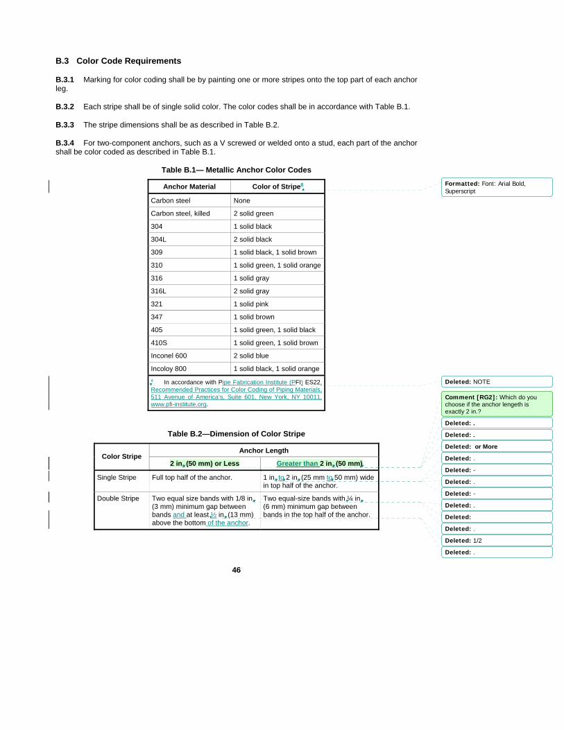
46
B.3 Color Code Requirements
B.3.1 Marking for color coding shall be by painting one or more stripes onto the top part of each anchor leg.
B.3.2 Each stripe shall be of single solid color. The color codes shall be in accordance with Table B.1.
B.3.3 The stripe dimensions shall be as described in Table B.2.
B.3.4 For two-component anchors, such as a V screwed or welded onto a stud, each part of the anchor shall be color coded as described in Table B.1.
Table B.1— Metallic Anchor Color Codes
Anchor Material Color of Stripea
Carbon steel None
Carbon steel, killed 2 solid green
304 1 solid black
304L 2 solid black
309 1 solid black, 1 solid brown
310 1 solid green, 1 solid orange
316 1 solid gray
316L 2 solid gray
321 1 solid pink
347 1 solid brown
405 1 solid green, 1 solid black
410S 1 solid green, 1 solid brown
Inconel 600 2 solid blue
Incoloy 800 1 solid black, 1 solid orange a In accordance with Pipe Fabrication Institute (PFI) ES22, Recommended Practices for Color Coding of Piping Materials, 511 Avenue of America’s, Suite 601, New York, NY 10011, www.pfi-institute.org.
Table B.2—Dimension of Color Stripe
Anchor Length Color Stripe
2 in. (50 mm) or Less Greater than 2 in. (50 mm)
Single Stripe Full top half of the anchor. 1 in. to 2 in. (25 mm to 50 mm) wide in top half of the anchor.
Double Stripe Two equal size bands with 1/8 in. (3 mm) minimum gap between bands and at least ½ in. (13 mm) above the bottom of the anchor.
Two equal-size bands with ¼ in. (6 mm) minimum gap between bands in the top half of the anchor.
Formatted: Font: Arial Bold,Superscript
Deleted: NOTE
Comment [RG2]: Which do you choose if the anchor lengeth is exactly 2 in.?
Deleted: .
Deleted: .
Deleted: or More
Deleted: .
Deleted: -
Deleted: .
Deleted: -
Deleted: .
Deleted:
Deleted: .
Deleted: 1/2
Deleted: .
47
Annex C (normative)
Refractory Compliance Data Sheet
C.1 Scope
This Annex describes the contents of and the requirements for compliance data sheets produced by refractory manufacturers.
C.2 Definition
Compliance data sheet – lists mechanical and chemical properties for a specified refractory material that are warranted by the manufacturer to be met if and when the product is tested by the listed procedure.
C.3 Application
Compliance data sheets are applicable to certification and qualification testing of refractory materials. They may also be used as a part of laboratory and technician qualification procedures. For as-installed testing, the compliance data sheet values may be modified in accordance with 8.4.4.1 and Table 3.
C.4 Requirements
C.4.1 Compliance data sheets shall be developed for any refractory material commonly used in or marketed to the refining and petrochemical Industry. They may be developed for any refractory material. Each compliance data sheet shall include a statement of identification as a compliance data sheet.
C.4.2 The refractory manufacturer shall provide compliance data sheets to the purchaser upon request. Standard compliance data sheets containing the data listed in C.4.3 shall be prepared in advance and retained on file for immediate transmission to the purchaser. Additional compliance data, as listed in C.4.3, shall be delivered to the purchaser within three weeks of the request.
C.4.3 Standard compliance data sheets shall include values for bulk density (green and fired), cold crushing strength, permanent linear change, chemical analysis and, for materials intended for erosive services, abrasion resistance. For plastic refractories the workability index shall also be included.
The purchaser may request compliance data on the following additional properties: Modulus of rupture, apparent porosity, and thermal conductivity. A note indicating that this information may be requested shall be included on each standard compliance data sheet, along with the test methods to be used.
C.4.4 Values on the compliance data sheet shall be based upon the test method listed in Table C.1 for the applicable property. Values shall be given for each temperature or range described in Table C.1. The compliance data sheet shall include a listing of the test method and edition (date) and the edition of this standard used for each value listed. Samples shall not contain metal reinforcing fibers.
C.4.5 Compliance data sheets shall include a statement similar to the following, “Dry gunned samples of <<Insert product name>> will meet the following values for the listed properties when tested in accordance with the specified method(s). All tests and listed properties conform to the requirements of API Standard 936, Annex C, and are based upon samples without metal reinforcing fibers unless otherwise noted. The property values are valid whenever the total water content is within the listed range.”
Formatted: Font: Bold
Deleted: compliance data sheets are not applicable to testing of as-installed materials unless specified by the owner. If specified f
Deleted: may

48
Table C.1—Requirements for Compliance Data Sheet Property Listings
Property Test Method a Temperature Range
Bulk density See 8.1.4 70ºF (20ºC) and after firing to 1500ºF (815ºC)
Provide an upper and lower limit
Cold crushing strength
ASTM C 133 as modified by 8.1.2 b
After firing to 1500ºF (815ºC) Provide a minimum value
Abrasion resistance c ASTM C 704 as modified by 8.1.3
After firing to 1500ºF (815ºC) Provide a maximum value
Permanent linear change
ASTM C 113 as modified by 8.1.5
After drying at 220ºF (105ºC) and after firing to 1500ºF (815ºC)
Provide an upper and lower limit of green-to-dried and dried-to-fired values
Chemical analysis ASTM E 1172, ASTM E 1184, or ASTM E 1479 d,e
Provide an upper and/or lower limit
Apparent porosity ASTM C 20 f After drying at 220ºF (105ºC) g and after firing to 1500ºF (815ºC)
Provide upper and a lower limit
Thermal conductivity ASTM C 201 and C 417 h At 800ºF (425ºC) (mean) and at 1000ºF (535˚C) (mean)
Provide a maximum value
Cold modulus of rupture
ASTM C 133 i After firing to 1500°F (815ºC) Provide a minimum value
Workability index ASTM C 181 65 to 75°F (18 to 24°C) Provide a minimum value
a Tests shall be conducted at a laboratory that has been mutually agreed upon by the owner, contractor, and manufacturer b Specimens shall be 2 in. 2 in. 2 in. (50 mm 50 mm 50 mm) c Applicable only to materials intended for abrasive service. d The test method is selected by the refractory manufacturer and noted on the compliance data sheet. e Perform analysis on blended and cast as formed samples of the finished product (not on the raw materials). f Specimens shall be one-half of the specimen used for permanent linear change testing, i.e., 2 in. 2 in. 4.5 in. (50 mm 50 mm x 112 mm). g Determination of the apparent porosity at 220ºF (105ºC) does not apply to phosbonded or plastic materials h Specimens to be dried but not fired. Data to be from the ascending curve i Specimens shall be 2 in. 2 in. 9 in. (50 mm 50 mm 225 mm). Ensure that opposing surfaces are parallel. In the tested position, a non-formed, non-cut face shall be on the bottom. For gunned properties, specimens shall be cut from the center (i.e., not the perimeter) of a gunned panel. One 2 in. x 9 in. (50 mm 225 mm) face shall be the surface of the gunned panel.
C.4.6 For applications involving water addition, compliance data sheets shall include a water range (variation in the amount of mixing water used) within which the property values listed for density, cold crushing strength, permanent linear change and abrasion resistance (when applicable) are valid. For dry gunning installations, this applies to pre-damping water only. The same water range shall be used when an optional property is requested. The refractory manufacturer shall determine the water range. A range of ±10 percent of the optimum water content is suggested.
C.4.7 The compliance data sheet shall include the installation method for which the data is valid (e.g., casting, dry gunning, wet gunning, etc). The compliance data shall be based upon specimens prepared by the listed method.
Formatted: Superscript
Deleted: 3
Deleted: 1
Deleted: 2
Deleted: 4
Deleted: a
Deleted: a
Deleted:
Deleted:
Deleted: .
Deleted: .
Deleted: .
Deleted: M
Deleted: .
Deleted: .
Deleted: .
Comment [RG3]: Where is this referenced in the table?
Deleted:
Deleted:

49
C.4.8 If a test is not applicable to the specific material (e.g., abrasion resistance for a lightweight insulating material), the words “not applicable” shall be entered into the appropriate place on the compliance data sheet.
C.4.9 The compliance data sheet shall include a manufacturer defined shelf life for the refractory.
C.5 Sample Compliance Data Sheet
Figure C.2 is intended to illustrate the content of a typical compliance data sheet. The layout/format shown is not significant and may be altered to comply with the manufacturer’s standard presentation. The information in the figure is fictitious and is not intended to portray any actual material or category/class of material. The designation (***) in the figure indicates a location that contains numerical values.
Formatted: Normal
Deleted: attachment
Deleted: attachment

50
IMPERVIUM 519
Compliance Data Sheet – Dry Gunned Installation
Impervium RP519 was developed to address all refining and petrochemical applications with a single product. It has excellent abrasion resistance and thermal insulating properties. It is also inert to all atmospheres found in refining and petrochemical processes. It may be installed by casting, vibracasting, or gunning.
Dry gunned samples of Impervium 519 will meet the following values for the listed properties when tested in accordance with the specified method(s). All tests and listed properties conform to the requirements of API Standard 936, Annex C, and are based upon samples without metal reinforcing fibers unless otherwise noted. The property values are valid whenever the total water content is within the listed range.
Water Content (***) to (***) weight percent
Bulk Density Green density (***) to (***) pcf (API Standard 936, 3rd edition) Density after firing (***) to (***) pcf
Cold Crushing Strength (***) psi (minimum) (ASTM C 133 - 97- as modified by API Standard 936, 3rd edition)
Permanent Linear Change (***) to (***) percent (dried to fired) (ASTM C 113 - 02- as modified by (***) to (***) percent (green to fired) API Standard 936, 3rd edition)
Abrasion Resistance (***) cc (maximum) (ASTM C 704 - 01- as modified by API Standard 936, 3rd edition)
Workability Index (***) (minimum) (ASTM C 181 – 03 as modified by API Standard 936, 3rd edition)
Shelf Life (***) months
Chemical Analysis (ASTM E 1172- 87(2003) X-Ray Florescence Spectroscopy)
Al2O3 SiO2 Fe2O3 Imp2O3 Misc
(***) to (***) (***) to (***) (***) to (***) (***) to (***) (***) to (***)
Additional Properties
Compliance values for the following properties are available upon request: Modulus of rupture (in accordance with ASTM C 133 - 97), apparent porosity (in accordance with ASTM C 20 - 00), and thermal conductivity (in accordance with ASTM C 201-93 and ASTM C 417-05).
Figure C.1—Sample Compliance Data Sheet
Formatted: Space After: 0 pt, Linespacing: single
Formatted: Space After: 0 pt
Formatted: Space After: 0 pt
Formatted: Space After: 0 pt, Linespacing: single
Formatted: Space After: 0 pt
Formatted: Space After: 0 pt
Formatted: Tabs: 3.68", Left
Formatted: Space After: 0 pt
Formatted: Subscript
Formatted: Subscript
Formatted: Subscript
Formatted: Subscript
Formatted: Subscript
Formatted: Subscript
Formatted: Subscript
Deleted: –
Deleted: e
Deleted: –
Deleted: –
Deleted: :
Deleted: API Standard 936)
Deleted: 1
Deleted:
Deleted: -
Deleted: -
Deleted: -
Deleted: -
Deleted: -
Deleted: -
Deleted: -
Deleted: -

51
Annex D (normative)
Refractory Personnel Certification
D.1 Examination
A written examination to certify refractory personnel within the scope of this standard shall be based on the Body of Knowledge for API 936 Refractory Personnel Certification Examination as published by API.
D.2 Certification
An API 936 certification will be issued when an applicant has successfully passed the API 936 certification exam.
Deleted: <#>Recertification¶D.3.1 Recertification is required three years from the date of issuance of the API 936 certificate. Recertification by written examination shall be required for refractory personnel who have not been actively engaged in refractory-related activities in the most recent three-year certification period.¶D.3.2 Refractory-related activities shall be defined by any one of the following:¶<#>refractory Installation;¶<#>refractory inspection;¶<#>refractory testing;¶<#>refractory repair.¶D.3.3 Once every other recertification period, (every six years) inspectors actively engaged as an inspector shall demonstrate knowledge of revisions to API 936 that were instituted during the previous six years. This requirement shall be effective six years from the inspector’s initial certification date. Inspectors who have not been actively engaged in refractory-related activities within the most recent three-year certification period shall recertify as required in D.3.1.

52
Bibliograpy
ACI1 SP-57, Refractory Concrete
API2 Std 560, Fired Heaters for General Refinery Service
ASME3 Boiler and Pressure Vessel Code, Section I, Power Boilers
ASME Boiler and Pressure Vessel Code, Section VIII, Pressure Vessels, Division 1
ASTM4 A 167, Standard Specification for Stainless and Heat-Resisting Chromium-Nickel Steel Plate, Sheet, and Strip
ASTM A 176, Standard Specification for Stainless and Heat-Resisting Chromium Steel Plate, Sheet, and Strip
ASTM A 576, Standard Specification for Steel Bars, Carbon, Hot-Wrought, Special Quality
ASTM A 580/A 580M, Standard Specification for Stainless Steel Wire
ASTM A 743/A 743M, Standard Specification for Castings, Iron-Chromium, Iron-Chromium-Nickel, Nickel Base, Corrosion-Resistant for General Applications
ASTM A 1011/A 1011M, Standard Specification for Steel, Sheet and Strip, Hot-Rolled Carbon, Structural, High-Strength Low-Alloy, and High-Strength Low-Alloy with Improved Formability
ASTM C 16, Standard Test Method for Load Testing Refractory Shapes at High Temperatures
ASTM C 20, Standard Test Methods for Apparent Porosity, Water Absorption, Apparent Specific Gravity, and Bulk Density of Burned Refractory Brick and Shapes by Boiling Water
ASTM C 24, Standard Test Method for Pyrometric Cone Equivalent (PCE) of Fireclay and High Alumina Refractory Materials
ASTM C 27, Standard Classification of Fireclay and High-Alumina Refractory Brick
ASTM C 109/C 109M, Standard Test Method for Compressive Strength of Hydraulic Cement Mortars (Using 2-in. or 50-mm Cube Specimens)
ASTM C 134, Standard Test Methods for Size, Dimensional Measurements, and Bulk Density of Refractory Brick and Insulating Firebrick
ASTM C 179, Standard Test Method for Drying and Firing Linear Change of Refractory Plastic and Ramming Mix Specimens
ASTM C 201, Standard Test Method for Thermal Conductivity of Refractories
ASTM C 401, Standard Classification of Alumina and Alumina-Silicate Castable Refractories
ASTM C 417, Standard Test Method for Thermal Conductivity of Unfired Monolithic Refractories
Deleted: ACI7 547R, Refractory Concrete: Abstract State-of-the-Art Report¶ACI 547.1R-89, State-of-the-Art Report Refractory Plastics and Ramming Mixes
Deleted: 8
Deleted: 1
Deleted: ASTM C 71, Standard Terminology Relating to Refractories

53
ASTM C 673, Standard Classification of Fireclay and High-Alumina Plastic Refractories and Ramming Mixes
ASTM C 832, Standard Test Method of Measuring the Thermal Expansion and Creep of Refractories Under Load
ASTM C 860, Standard Practice for Determining the Consistency of Refractory Castable Using the Ball-In-Hand Test
ASTM C 862, Standard Practice for Preparing Refractory Concrete Specimens by Casting
ASTM C 865, Standard Practice for Firing Refractory Concrete Specimens
ASTM C 914, Standard Test Method for Bulk Density and Volume of Solid Refractories by Wax Immersion
ASTM C 1113, Standard Test Method for Thermal Conductivity of Refractories by Hot Wire (Platinum Resistance Thermometer Technique)
ASTM C 1171, Standard Test Method for Quantitatively Measuring the Effect of Thermal Shock and Thermal Cycling on Refractories
ASTM C 1445, Standard Test Method for Measuring Consistency of Castable Refractory Using a Flow Table
ASTM C 1446, Standard Test Method for Measuring the Consistency and Working Time of Self-Flowing Castable Refractories
ASTM E 177, Standard Practice for Use of the Terms Precision and Bias in ASTM Test Methods
ASTM E 691, Standard Practice for Conducting an Interlaboratory Study to Determine the Precision of a Test Method
ASTM E 1172, Standard Practice for Describing and Specifying a Wavelength-Dispersive X-Ray Spectrometer
ASTM E 1184, Standard Practice for Electrothermal (Graphite Furnace) Atomic Absorption Analysis
ASTM E 1479, Standard Practice for Describing and Specifying Inductively-Coupled Plasma Atomic Emission Spectrometers
SSPC6 SP6/NACE No. 3, Commercial Blast Cleaning
Deleted: PFI9 ES 22, Recommended Practices for Color Coding of Piping Materials
Deleted: 10