apex dynamics, inc. - amazon web services€¦ · apex 1 characteristic ... h1 108 32 90 40 38 70...
TRANSCRIPT

APEX-2011-09-AE / AER-2.0E-4.2V
No.10, Keyuan 3rd Rd., Situn District, Taichung City 407, Taiwan (R.O.C.)
Tel: 886 4 23550219 / Fax: 886 4 23550218
E-mail: [email protected]
Website: www.apexdyna.com
APEX DYNAMICS, INC.
APEX 1
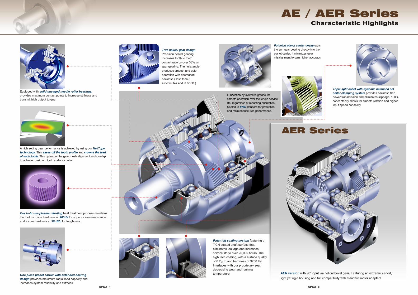
Characteristic Highlights
AE / AER Series
Lubrication by for
smooth operation over the whole service
life, regardless of mounting orientation.
Sealed to standard for protection
and maintenance-free performance.
synthetic grease
IP65
Equipped with
provides maximum contact points to increase stiffness and
transmit high output torque.
solid uncaged needle roller bearings,
A high setting gear performance is achieved by using our
This and
This optimizes the gear mesh alignment and overlap
to achieve maximum tooth surface contact.
HeliTopo
technology. eases off the tooth profile crowns the lead
of each tooth.
Our in-house plasma nitriding
900Hv
30 HRC
heat treatment process maintains
the tooth surface hardness at for superior wear-resistance
and a core hardness at for toughness.
One piece planet carrier with extended bearing
design provides maximum radial load capacity and
increases system reliability and stiffness.
True helical gear design
Precision helical gearing
increases tooth to tooth
contact ratio by over 33% vs
spur gearing. The helix angle
produces smooth and quiet
operation with decreased
backlash ( less than 8
arc-minutes and 56dB ).≦
Patented planet carrier design puts
the sun gear bearing directly into the
planet carrier. It minimizes gear
misalignment to gain higher accuracy.
Triple split collet with dynamic balanced set
collar clamping system provides backlash free
power transmission and eliminates slippage. 100%
concentricity allows for smooth rotation and higher
input speed capability.
APEX 2
AER version o with 90 input via helical bevel gear. Featuring an extremely short,
light yet rigid housing and full compatibility with standard motor adapters.
AER Series
Patented sealing system featuring a
TiCN coated shaft surface that
eliminates leakage and increases
service life to over 20,000 hours. The
high tech coating, with a surface quality
of 0.2μm and hardness of 3700 Hv.
Interfaces with our proprietary seal,
decreasing wear and running
temperature.

AE050 AE070 AE155 AE205 AE235AE090 AE120
D1
D2
D3 j6
D4 h6
D5
D6
D7
D8
D9
L1
L2
L3
L4
L5
L6
L7
L9
L8
L10
44
12
35
22
53
50
45.5
24.5
4
1
14
2
47
8
4.5
10
46
30
30
3.5
48
19.5
91
13.25
19.5
4
14
62
16
52
22
36
6.5
1
25
2
62
10
4.8
12.5
70
34
50
8
60
19
117
13.5
37
5
18
140
40
120
75
50
97
15
3
63
5
119.5
20
12
36
165
60
130
6
142
22.5
239
15
53.5
12
43
184
55
160
95
100
15
3
70
6
159
22
15
42
215
85
180
6
190
29
288
20.75
79.5
16
59
210
75
180
115
70
126
18
3
90
7
175.5
28
15
42
235
116
200
6
220
63
364.5
53.5
106.5
20
79.5
C14
C24
C44
C54
C64
C74
C84
C94
C104
C114
B1 h9
H1
108
32
90
40
38
70
17.5
1.5
40
5
97
16
10
28
130
50
110
5
115
19.5
186.5
13
46
10
35
80
22
68
30
33.5
46
8.5
1
32
3
80.5
12
7.2
19
100
40
80
4
90
17
143.5
10.75
35.5
6
24.5
C34
70
70
53.4
104
90
77
130
120
102
162
125
155
205
205
160
260
235
205
Dimension
M4 x 0.7P
M4 x 0.7P
M5 x 0.8P
M5 x 0.8P
M6 x 1P
M8 x 1.25P
M8 x 1.25P
M12 x 1.75P
M10 x 1.5P
M16 x 2P
M12 x 1.75P
M20 x 2.5P
M16 x 2P
M20 x 2.5P
M4 x 0.7P M5 x 0.8P M6 x 1P M8 x 1.25P M10 x 1.5P M12 x 1.75P M12 x 1.75P
19 / 24≦ ≦ 32≦ 38≦ 48≦ 55≦
Emergency Stop Torque T2NOT2
Max. Radial Load F2rB
3
Max. Axial Load F2aB
3
Noise Level (n =3000rpm, No Load)1 dB(A)
1. Ratio ( i=N / N )in out 3. Applied to the output shaft center @ 100 rpm
S1 service life 10,000 hrs (Consult us)
2. T = 60% of T2B 2NOT4. C1~C11 are motor specific dimensions (metric std shown). Refer to Apexdyna.com and Design Tool to view your specific motor mounting system.
AE050 ratio 5, 10 offers C3 12 option.≦
14 / 16≦ ≦
Synthetic lubrication oils
11 / 12≦ ≦
AE070 ratio 5, 10 offers C3 16 option.≦
o o-10 C~90 C

APEX 5
AE Series
[unit: mm]
AE050 AE070 AE155 AE205 AE235AE090 AE120
D1
D2
D3 j6
D4 h6
D5
D6
D7
D8
D9
L1
L2
L3
L4
L5
L6
L7
L9
L8
L10
44
12
35
22
53
50
24.5
4
1
14
2
74
8
4.5
10
46
30
30
3.5
48
19.5
118
13.25
19.5
4
14
62
16
52
22
36
6.5
1
25
87.5
10
2
4.8
12.5
46
30
30
19.5
143
19.5
5
18
140
40
120
75
50
97
15
3
63
5
176
20
12
36
130
50
110
5
115
19.5
292.5
13
46
12
43
184
55
160
95
100
125
15
3
70
6
22
214.5
15
42
165
60
130
6
142
22.5
337
15
53.5
16
59
210
75
180
115
70
126
18
3
90
28
260
7
15
42
215
85
180
6
190
29
415
20.75
79.5
20
79.5
C15
C25
C45
C55
C65
C75
C85
C95
C105
C115
B1 h9
H1
108
32
90
40
38
70
17.5
1.5
40
5
138.5
16
10
28
100
40
80
90
17
225.5
10.75
35.5
10
35
80
22
68
30
33.5
46
8.5
1
32
3
113.5
12
7.2
19
70
34
50
8
60
19
178.5
13.5
37
6
24.5
C35
70
70
104
90
130
120
162
155
102
205
205
260
235
160
Dimension
M4 x 0.7P
M4 x 0.7P
45.5
M5 x 0.8P
M5 x 0.8P
45.5
M6 x 1P
53.4
M8 x 1.25P
M12 x 1.75P
77
M10 x 1.5P
M16 x 2P
M12 x 1.75P
M20 x 2.5P
M16 x 2P
M20 x 2.5P
M4 x 0.7P M4 x 0.7P M5 x 0.8P M6 x 1P M8 x 1.25P M10 x 1.5P M12 x 1.75P
3.5 4
48
13.25
11 / 12≦ ≦ 14 / 15.875 / 16≦ ≦ ≦ 19 / 24≦ ≦ 32≦ 38≦ 48≦
ØD190°
D2
ØD
5
ØD
4h6
ØD
8
ØD
7
L2 L8 C8
L3 L1
L7
L4
C9
C7
ØC1
45°
45°
C11
C10
ØC
5
C6 C2
ØD
9
C4
ØC
3
H1
B1 h9
D6
D3 j6
L9
L5L6
L10
M8 x 1.25P
Dimensions (2-stage, Ratio i=15~100) Specifications
AER Series
Gearbox Performance
1.0
1.3
2.1
2.0
5.8
4.6
11.2
11.1
22.4
21.8
46.8
43.7
78.0
81.9o o-10 C~90 C
AER050 AER070 AER090 AER120 AER155 AER205 AER235
1
2
1,2
1,2
1,2
1,2
IP65
3~20
25~200
3~200
3~200
3~200
3~200
Model No.
Nominal output torque T2N Nm
Degree of gearbox protection
Weight kg
Operating temp
Lubrication
Mounting position
0C
all directions
Stage Ratio1
≦61 ≦63 65≦ 68≦ ≦70 ≦72 74≦
9
12
15
18
19
17
15
20
19
17
14
14
20
19
17
14
36
48
60
55
50
45
90
120
150
150
140
120
195
260
325
310
300
260
342
520
650
600
550
500
588
1,040
1,200
1,100
1,100
1,000
1,140
1,680
2,000
1,900
1,800
1,600
60
55
50
45
40
60
55
50
45
40
150
150
140
120
100
100
150
140
120
100
120
325
310
300
260
230
230
310
300
260
230
260
650
600
550
500
450
650
600
550
500
450
550
1,200
1,100
1,100
1,000
900
1,200
1,100
1,100
1,000
900
1,000
2,000
1,900
1,800
1,600
1,500
2,000
1,900
1,800
1,600
1,500
1,600
3
4
5
6
7
8
14 40 100 230 450 900 1,5009
14 40 100 230 450 900 1,50010
42 140 300 550 1,100 1,80014
1420
25
30
35
40
45
50
60
70
80
90
14 40 100 230 450 900 1,500100
150 310 600 1,100 1,900120
140 300 550 1,100 1,800140
160
100 230 450 900 1,500180
100 230 450 900 1,500200
1
2
1415
40 100 230 450 900 1,50020
APEX 6
0.090.090.09 0.09 0.35 2.25 6.84 23.4 68.9
1
2kg‧cm
Gearbox Inertia
Mass Moments of Inertia J1
AER050 AER070 AER090 AER120 AER155 AER205 AER235Model No. Stage
0.09 0.35 2.25 6.84 23.4 68.9 135.43~10
1520
25~100
Ratio1
0.07 1.87 6.25 21.8 65.6 119.814
0.31 1.87 6.25 21.8 65.6120~200
0.07 1.87 6.25 21.8 65.6 119.820
2
702
390
1,377
765
2,985
1,625
6,100
3,350
8,460
4,700
13,050
7,250
8,700
18,000
1,2
1,2
1
2
3~200
3~200
3~20
25~200Backlash arcmin
N
N
Max. radial load F2rB
3
Max. axial load F2aB
3
1,2 3~200Nm 3 times of nominal output torque
20,0001,2 3~200hrService life *
≦10 ≦10 ≦10 ≦10 ≦10 ≦10 ≦10
≦14 ≦14 ≦14 ≦14 ≦14 ≦14 ≦14
rpmNominal Input Speed n1N 5,000 5,000 4,000 4,000 3,000 3,000 2,0003~2001,2
rpmMax. Input Speed n1B 10,000 10,000 8,000 8,000 6,000 6,000 4,0003~2001,2
Nm/arcminTorsional Rigidity 3 7 14 25 50 145 2253~2001,2
%≧95%3~201
≧92%25~2002Efficiency
Emergency Stop Torque T2NOT
2
Noise Level (n =3000rpm, No Load)1 dB(A)
5. C1~C11 are motor specific dimensions (metric std shown). Refer to Apexdyna.com and Design Tool to view your specific motor mounting system. 1. Ratio ( i=N / N )in out 3. Applied to the output shaft center @ 100 rpm2. T = 60% of T2B 2NOT
S1 service life 10,000 hrs (Consult us)
Synthetic lubrication oils
11 / 12≦ ≦

APEX 7 APEX 8
[unit: mm]
AER050 AER070 AER155 AER205 AER235AER090 AER120
D1
D2
D3 j6
D4 h6
D5
D6
D7
D8
L1
L2
L3
L4
L5
L6
L7
L9
L8
L10
44
C14
C24
C44
C54
C64
C74
C84
C94
C104
C34
Dimension
M4 x 0.7P
12
35
22
53
50
24.5
4
1
14
2
8
4.5
10
46
30
30
48
19.5
100.5
13.25
74
4
14
3.5
M4 x 0.7P
115.5
M4 x 0.7P
62
M5 x 0.8P
16
52
22
70
70
----
36
6.5
1
25
2
10
4.8
12.5
70
34
50
60
19
116.5
13.5
81.5
5
18
8
M5 x 0.8P
146
M5 x 0.8P
80 108 140 184 210
M6 x 1P M8 x 1.25P M10 x 1.5P M12 x 1.75P M16 x 2P
22 32 40 55 75
68 90 120 160 180
30 40 75 95 115
104 130 162 205 260
90 120 155 205 235
33.5 38 50 -- 70
46 70 97 100 126
8.5 17.5 15 15 18
1 1.5 3 3 3
32 40 63 70 90
3
12
5
16
5
20
6
22
7
28
7.2 10 12 15 15
19 28 36 42 42
100 130 165 215 235
40 50 60 85 116
80 110 130 180 200
90 115 142 190 220
17 19.5 22.5 29 63
159.5 199 245.5 316 398.5
10.75 13 15 20.75 53.5
107.5
6
24.5
134
10
35
164.5
12
43
213.5
16
59
268.5
20
79.5
4 5 6 6 6
M6 x 1P M8 x 1.25P M10 x 1.5P M12 x 1.75P M12 x 1.75P
201 252 324.5 379.5 461.5
M8 x 1.25P M12 x 1.75P M16 x 2P M20 x 2.5P M20 x 2.5P
Dimensions (1-stage, Ratio i=3~20)
C114
H1
B1 h9
[unit: mm]
Dimensions (2-stage, Ratio i=25~200)
AER Series
11 / 12≦ ≦ 14 / 16≦ ≦ 19 / 24≦ ≦ 32≦ 38≦ 48≦ 55≦
AER050 AER070 AER155 AER205 AER235AER090 AER120
D1
D2
D3 j6
D4 h6
D5
D6
D7
D8
L1
L2
L3
L4
L5
L6
L7
L9
L8
L10
44
C15
C25
C45
C55
C65
C75
C85
C95
C105
C35
Dimension
M4 x 0.7P
12
35
22
53
50
24.5
4
1
14
2
8
4.5
10
46
30
30
48
19.5
100.5
13.25
74
4
14
3.5
M4 x 0.7P
142.5
M4 x 0.7P
62
M5 x 0.8P
16
52
22
70
70
--
36
6.5
1
25
2
10
4.8
12.5
46
30
30
48
19.5
109
13.25
74
5
18
3.5
M4 x 0.7P
167.5
M5 x 0.8P
80 108 140 184 210
M6 x 1P M8 x 1.25P M10 x 1.5P M12 x 1.75P M16 x 2P
22 32 40 55 75
68 90 120 160 180
30 40 75 95 115
104 130 162 205 260
90 120 155 205 235
33.5 38 50 -- 70
46 70 97 100 126
8.5 17.5 15 15 18
1 1.5 3 3 3
32 40 63 70 90
3
12
5
16
5
20
6
22
7
28
7.2 10 12 15 15
19 28 36 42 42
70 100 130 165 215
34 40 50 60 85
50 80 110 130 180
60 90 115 142 190
19 17 19.5 22.5 29
133.5 172.5 215 267 343.5
13.5 10.75 13 15 20.75
81.5
6
24.5
107.5
10
35
134
12
43
164.5
16
59
213.5
20
79.5
8 4 5 6 6
M5 x 0.8P M6 x 1P M8 x 1.25P M10 x 1.5P M12 x 1.75P
207.5 283 358 422.5 506.5
M8 x 1.25P M12 x 1.75P M16 x 2P M20 x 2.5P M20 x 2.5P
C115
H1
B1 h9
11 / 12≦ ≦ 14 / 15.875 / 16≦ ≦ ≦ ≦19 / 24≦ 32≦ 38≦ ≦48
ØD1
D2
90°
ØD
5
ØD
4 h
6
ØD
8
ØD
7
L3
L1
L7
L2
L8
L4
C1
0
C8
C4
C6
ØC3
ØC5
C11
C9
C7
45°
45°
C2
L6 L5
L9
L10
H1
ØD3 j6
B1h9
D6
Ø C1
D2
90°
L4
ØD
5
ØD
4 h
6
ØD
8
ØD
7
L3 L7
L1L2
L8
C11
C1
0
C8
ØC3
ØC5
C6C4
45°
45°
C2
L6 L5
L9
L10
B1 h9
H1
Ø D3 j6
C7
C9
Ø C1Ø D1
D6
--
4. C1~C11 are motor specific dimensions (metric std shown). Refer to Apexdyna.com and Design Tool to view your specific motor mounting system. 5. C1~C11 are motor specific dimensions (metric std shown). Refer to Apexdyna.com and Design Tool to view your specific motor mounting system.
11 / 12≦ ≦

APEX 9 APEX 10
Output Dimensions Ordering Code
AE155 / AER155
AE205 / AER205
AE120 / AER120
AE235 / AER235
AE050 / AER050
AE070 / AER070
AE090 / AER090
1,000
100,000
60,000
40,000
20,000
10,000
6,000
4,000
2,000
3002000100060040020010060402010
Pe
rmit
ted
ra
dia
l lo
ad
F [
N ]
2rB
on
ce
nte
r p
os
itio
n o
f s
ha
ft
Output Speed n [ rpm ]2
If radial force F exert 2r
on the center of the
output shaft X=1/2 x L.
Under various
operating condition the
lifetime is over 20,000
hours.
The permitted radial
load is given on left
diagram.
If radial force F not 2r
exert on the center of
the output shaft X<1/2
x L or X>1/2 x L
The permitted radial
and axial load can be
calculated by the
position load factor K b
on the left diagram.
1.5
1.4
1.3
1.2
1.1
1.0
0.9
0.8
0.7
0.6
0.5
0.4
0.3
0 40 80 120 160 200 240 280 320 360 400
AE050 / AER050
AE070 / AER070
AE090 / AER090
AE120 / AER120
AE155 / AER155
AE205 / AER205
AE235 / AER235
Position X [ mm ]
Po
sit
ion
lo
ad
fa
cto
r k
b
*Continuous running reduces service life by 50%
*
[unit: mm]
ØD2
ØD3
L1
45°
45°
ØD
4h
6
L4
L2
L3
Ø D1
D1 D2 L1 L2 L3D3 h6D4
AE050(AER050)-NEMA 23AE050 -PX60(AER050)AE070 -Metric(AER070)AE070 -NEMA 34(AER070)
AE090 -NEMA 34(AER090)
AE070 -DT90 / PX90(AER070)AE090 -IEC 63D5 B5(AER090)
AE090 -NEMA 42(AER090)
AE120 -NEMA 56(AER120)AE155 -B5(AER155)AE205 -B5(AER205)AE235 -B5(AER235)
66.6757090
98.425
98.425
100
100
115
125.73125.73
149.225175230275
Dimension L4
65.66.65.6
5.5
6.6
6.5
9
77.16.6111317
7780.5106115
122
120
122
140
144170170196277317
38.15050
73.08
73.025
80
80
95
55.5855.499114.3130180235
57.2608086
92
90
92
105
107127127160210240
22.53
2.5
2.5
3
2.5
3
41.53555
88.5118
12.5
8
12.5
10.5
14.521.517.5202323
18.518.528
30.5
36
31
36
38.5
35.550
55.58282
108
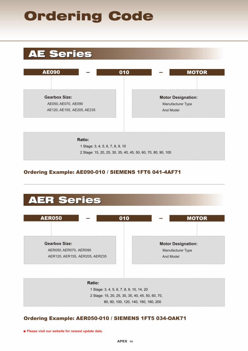
Ordering Example: AE090-010 / SIEMENS 1FT6 041-4AF71
AE090 010 MOTOR- -
Gearbox Size:
AE050, AE070, AE090
AE120, AE155, AE205, AE235
Ratio:
1 Stage: 3, 4, 5, 6, 7, 8, 9, 10
2 Stage: 15, 20, 25, 30, 35, 40, 45, 50, 60, 70, 80, 90, 100
AE SeriesAE Series
Ordering Example: AER050-010 / SIEMENS 1FT5 034-OAK71
Gearbox Size:
AER050, AER070, AER090
AER120, AER155, AER205, AER235
AER SeriesAER Series
Ratio:
1 Stage: 3, 4, 5, 6, 7, 8, 9, 10, 14, 20
2 Stage: 15, 20, 25, 30, 35, 40, 45, 50, 60, 70,
80, 90, 100, 120, 140, 160, 180, 200
Motor Designation:
Manufacturer Type
And Model
Front plate option
AER050 010 MOTOR- -
Motor Designation:
Manufacturer Type
And Model
Please visit our website for newest update data.
AE120 -NEMA 42(AER120)
AE090 -DT90 / PX90(AER090)
APEX 9 APEX 10
Output Dimensions Ordering Code
AE155 / AER155
AE205 / AER205
AE120 / AER120
AE235 / AER235
AE050 / AER050
AE070 / AER070
AE090 / AER090
1,000
100,000
60,000
40,000
20,000
10,000
6,000
4,000
2,000
3002000100060040020010060402010
Pe
rmit
ted
ra
dia
l lo
ad
F [
N ]
2rB
on
ce
nte
r p
os
itio
n o
f s
ha
ft
Output Speed n [ rpm ]2
If radial force F exert 2r
on the center of the
output shaft X=1/2 x L.
Under various
operating condition the
lifetime is over 20,000
hours.
The permitted radial
load is given on left
diagram.
If radial force F not 2r
exert on the center of
the output shaft X<1/2
x L or X>1/2 x L
The permitted radial
and axial load can be
calculated by the
position load factor K b
on the left diagram.
1.5
1.4
1.3
1.2
1.1
1.0
0.9
0.8
0.7
0.6
0.5
0.4
0.3
0 40 80 120 160 200 240 280 320 360 400
AE050 / AER050
AE070 / AER070
AE090 / AER090
AE120 / AER120
AE155 / AER155
AE205 / AER205
AE235 / AER235
Position X [ mm ]
Po
sit
ion
lo
ad
fa
cto
r k
b
*Continuous running reduces service life by 50%
*
[unit: mm]
ØD2
ØD3
L1
45°
45°
ØD
4h
6
L4
L2
L3
Ø D1
L
X
F 2r
F2a2 F2a1
F Radial Load2r
F Axial Load2a
D1 D2 L1 L2 L3D3 h6D4
AE050(AER050)-NEMA 23AE050 -PX60(AER050)AE070 -Metric(AER070)AE070 -NEMA 34(AER070)
AE090 -NEMA 34(AER090)
AE070 -DT90 / PX90(AER070)AE090 -IEC 63D5 B5(AER090)
AE090 -NEMA 42(AER090)
AE120 -NEMA 56(AER120)AE155 -B5(AER155)AE205 -B5(AER205)AE235 -B5(AER235)
66.6757090
98.425
98.425
100
100
115
125.73125.73
149.225175230275
Dimension L4
65.66.65.6
5.5
6.6
6.5
9
77.16.6111317
7780.5106115
122
120
122
140
144170170196277317
38.15050
73.08
73.025
80
80
95
55.5855.499114.3130180235
57.2608086
92
90
92
105
107127127160210240
22.53
2.5
2.5
3
2.5
3
41.53555
88.5118
12.5
8
12.5
10.5
14.521.517.5202323
18.518.528
30.5
36
31
36
38.5
35.550
55.58282
108
Ordering Example: AE090-010 / SIEMENS 1FT6 041-4AF71
AE090 010 MOTOR- -
Gearbox Size:
AE050, AE070, AE090
AE120, AE155, AE205, AE235
Ratio:
1 Stage: 3, 4, 5, 6, 7, 8, 9, 10
2 Stage: 15, 20, 25, 30, 35, 40, 45, 50, 60, 70, 80, 90, 100
AE SeriesAE Series
Ordering Example: AER050-010 / SIEMENS 1FT5 034-OAK71
Gearbox Size:
AER050, AER070, AER090
AER120, AER155, AER205, AER235
AER SeriesAER Series
Ratio:
1 Stage: 3, 4, 5, 6, 7, 8, 9, 10, 14, 20
2 Stage: 15, 20, 25, 30, 35, 40, 45, 50, 60, 70,
80, 90, 100, 120, 140, 160, 180, 200
Motor Designation:
Manufacturer Type
And Model
Front plate option
AER050 010 MOTOR- -
Motor Designation:
Manufacturer Type
And Model
Please visit our website for newest update data.
AE120 -NEMA 42(AER120)
AE090 -DT90 / PX90(AER090)

APEX-2011-09-AE / AER-2.0E-4.2V
No.10, Keyuan 3rd Rd., Situn District, Taichung City 407, Taiwan (R.O.C.)
Tel: 886 4 23550219 / Fax: 886 4 23550218
E-mail: [email protected]
Website: www.apexdyna.com
APEX DYNAMICS, INC.