apex and the sketch powerview - a la mode iv windows sketching library. this guide is a “quick...
TRANSCRIPT

Apex a Page 7.1
Apex and the Sketch Po ew
Apex and the Sketch PowerViewThe Sketch PowerView is your complete interface for digital stheir resulting area calculations to transfer into your form. InPowerView, you can even access sketches from previous repBy including the sketch as part of your electronic report, you gbenefits:• Floorplan looks professional.• Sketch is saved inside the report file with rest of data.• Sketch prints on a WinTOTAL form with the rest of
Header information transfers automatically to the WinTOT• Areas can be automatically calculated and transferred to Included with the WinTOTAL Professional or Enterprise EdApex IV Windows Sketching Library. This guide is a “Quick Sfor Apex, to get you familiar with the essential drawing funcprogram. For a more detailed reference, access the full guide menu in Apex IV Windows. If you prefer WinSketch, it can bwith WinTOTAL reports through the Sketch PowerView too. Caccess our “Sketch PowerView with WinSketch” guide.
Starting a New Floorplan with ApexThe Sketch PowerView incorporates all of your sketching anfunctions on one screen.1.2.
3.4.
5.Yo
Figure I Apex IV Windows Sketching Library is so easy to use that, with a little practiceand some accurate measurements, you can create sketches like this one in around fiveminutes.
nd the Sketch PowerView • Starting a New Floorplan with Apex 2/12/2002
Click on the Sketch PowerView.Under the Area calculations heading, select the appropriate optionsfor transferring areas back to the other forms in your report.WinTOTAL will remember these for next time.Click the New button in the top, left-hand corner of the window.In the dialog box that opens, select the page style you want to usefrom the drop-down list labeled Page formatClick on OK.
u should see the Apex application appear on screen.
werVi
ketches and the Sketchorts.ain several
your report.AL form.your report.ition is thetart” tutorialtions of thevia the Helpe integratedlick here to
d floor plan

Ap the Sketch PowerView • The Apex Environment 2/12/2002 Page 7.2
Apex and the Sketch PowerViewThe Apex Environment
Apex User Interface Bar - Displays current file name and scale of sketch 6 Command ck access to commandsDown Menu - Allows access to every function in Apex 7 Sketch pag asily navigate between pagesEdit Toolbar - Provides convenient access to commands 8 Tracking P ut the current line being drawning Toolbar - Allows the mouse-user to quickly and easily drawlex shapes, arcs, etc.
9 Help Status mation about the current status of Apex forWindows
s Toolbar - Displays status of current or last area completed,ding square footage
10 Drawing Po area of the sketches created and edited
ex and
1 Title2 Pull 3 File/4 Draw
comp5 Statu
inclu
Pad - Gives mouse users quie Indicator - Allows user to eort - Displays information abo Line - Provides helpful infor
rt - Represents the printable

Apex a Page 7.3
Apex and the Sketch PowerView
Basic Drawing ConceptsThere are three basic steps to drawing a sketch using Apex.1. Define an area.2. Draw and close the area.3. Add text, icons, etc.Before you begin drawing perimeter walls, Apex will ask you to define andname the type of area you will be drawing. For example, Apex haspredefined areas such as Gross Living Area (GLA), Garage, Basement,etc. The area definition is necessary for Apex to handle the distribution ofarea calculations on printouts and to pass data to WinTOTAL. To define an area, click the Define Area button on the right. (It’s the firstbutton.) After you define an area, you may begin drawing. Press etochange to Draw Mode. Your Drawing Cursor will look like this:
Engineering InputEngineering Mode input, the most commonly used input mode, refers to adecimal unit of measure. For example, 25.5 is the decimal equivalent of25 feet, 6 inches. To begin drawing a line using engineering mode input, 1. Press eto change to Draw Mode, then type in the line’s length.
Your input will appear at the bottom of the screen in the Help StatusLine.
2.
3.Skusdrathe
Type
ame tab of the Define Area dialog allowsault name (“First Floor”) chosen by Apex orme of your choosing. The Name tab alsoct whether the area will be a positive or a
nd the Sketch PowerView • Basic Drawing Concepts 2/12/2002
Press one of the arrow keys to move the cursor. (The direction youchoose will determine the direction to which the line is drawn.) Press eto set the dimension and eagain to anchor the line.
etching in this fashion is much quicker and easier than drawing bying the arrow keys alone. As you can see in the example below,wing a line 25.5 feet to the right, takes only three easy steps. That’s allre is to it!
25.5, press x Press eto set dimension Press eto anchor line
Figure 2 The Nyou to use the defgive the area a naallows you to selenegative area.
Apex Page 7.4
Apex and the Sketch PowerViewDrawing diagonal lines is just as easy. Just as the Arrow keys define up,down, left and right movement, Apex has se oup of keys for 45degree diagonal movement.
• {will draw a line 45 degrees up an .
• }will draw a line 45 degrees down ght.
• gwill draw a line 45 degrees up an
• dwill draw a line 45 degrees down ft.For example, to draw a 20 foot line at a 4 ward angle to theright, all you need to do is type 20, press { e.A more flexible method of drawing angles is y typing 30 (rise),pressing w, typing 40 (run), pressing x, ssing e. Thiswill draw a 50 foot line upward and to the cond method willallow you to draw any angle, as long as y angle’s rise andrun.In addition to simple 45 degree angles and and run, Apex willalso enable you to specify and angle and This is describedlater on “Specifying an exact angle and l age 7.
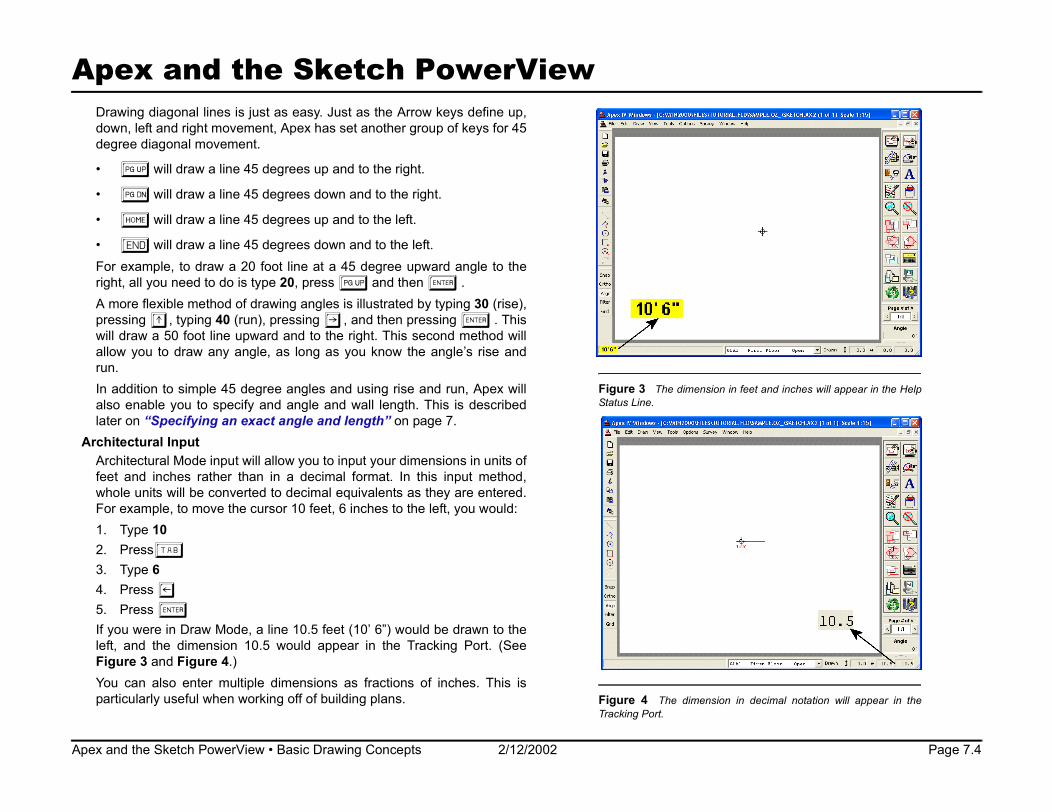
Architectural InputArchitectural Mode input will allow you to in ensions in units offeet and inches rather than in a decimal format. In this input method,whole units will be converted to decimal equivalents as they are entered.For example, to move the cursor 10 feet, 6 inches to the left, you would:
Figure 3 T n feet and inches will appear in the HelpStatus Line.
decimal notation will appear in the
and the Sketch PowerView • Basic Drawing Concepts 2/12/2002
1. Type 10 2. PressT3. Type 64. Press z5. Press e If you were in Draw Mode, a line 10.5 feet (10’ 6”) would be drawn to theleft, and the dimension 10.5 would appear in the Tracking Port. (SeeFigure 3 and Figure 4.)You can also enter multiple dimensions as fractions of inches. This isparticularly useful when working off of building plans. Figure 4 The dimension in
Tracking Port.
t another gr
d to the right
and to the ri
d to the left.
and to the le5 degree up
and then illustrated b
and then preright. This seou know the
using rise wall length.ength” on p
put your dim
he dimension i

Apex Page 7.5
Apex and the Sketc werViewFor example, to draw a line 20 feet 6 ½ inches:1. Type 102. PressT3. Type 64. PressT5. Type 1/26. Pressz7. Press e This line would display as 20.54 feet in the Track post on thescreen as 20.5.[Note: While by default, dimensions are rounded al place onthe screen, they are calculated with double floati uracy to 15to 16 decimal places. The number of decimal p on screencan be set between 0 and 4 decimal places by se recision tabunder the Options/Configuration menu.]
Drawing a SketchThe next few pages will lead you through a step cess of howthe illustrated sketch to the right is drawn. Thes provide yousome insight to the functions and procedures y e to createalmost any sketch. Once you have become famil e functions,you will find that sketching, regardless of the complexity of the property,may be accomplished in just a matter of minutes.
Dra
Figure 5 This s ear complicated, but with Apex IV Windows, it’sonly a few keyboa ouse clicks away. Best of all, your calculationstransfer back into ms, making your job that much easier.
, click OK to open the Name dialog, where youand adjust calculations to positive or negative.
and the Sketch PowerView • Drawing a Sketch 2/12/2002
wing the First FloorUsing Apex’s Quick Keys feature, we will begin drawing the exterior of theFirst Floor area. [Note: If you place a line incorrectly, you can erase it by pressing c. Ifnecessary, you may continue pressing call the way back to the firstline or any point in between. Conversely, pressing h will replace anylines you just deleted.]1. Click the Define Area button to define the Gross Living Area.
Your Arrow Cursor will change to the Drawing Cursor, indicating that your “pen” is down, and any cursor movement will draw a line.
2. Type 24, press x, press etwice.
Figure 6 After defining an areacan give the area a unique name
h Po
ing Port and
to one decimng point acclaces shownlecting the P
-by-step proe steps will ou can utiliziar with thes
ketch might apprd entries and mWinTOTAL’s for
Apex a Page 7.6
Apex and the S PowerViewAs you type in the dimension, you ar at the bottom left of the screen, highlighted in yello• Pressing x will draw the lin ngth. • Pressing ewill end and and the dimension
will appear auto-placed/rotate location. 3. Type 9.8, press y, press et
You are drawing a line 9.8 feet do the first time will end the line, and the dimension w right of the line. Press e again to anchor the ce.
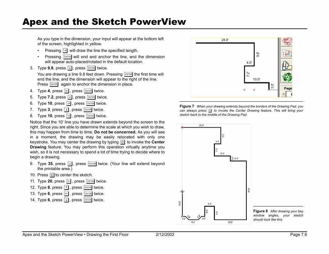
4. Type 4, press z, press etw5. Type 7.2, press y, press et6. Type 10, press x, press et7. Type 3, press y, press etw8. Type 10, press x, press etNotice that the 10’ line you have draw nd the screen to theright. Since you are able to determine ch you wish to draw,this may happen from time to time. Do ned. As you will seein a moment, the drawing may b ted with only onekeystroke. You may center the drawin o invoke the CenterDrawing feature. You may perform irtually anytime youwish, so it is not necessary to spend a g to decide where tobegin a drawing.9.
1011121314
Figure 7 When your drawing extends beyond the borders of the Drawing Pad, youcan always press C to invoke the Center Drawing feature. This will bring yoursketch back to the middle of the Drawing Pad.
Figure 8 After drawing your baywindow angles, your sketchshould look like this.
nd the Sketch PowerView • Drawing the First Floor 2/12/2002
Type 35, press y, press etwice. (Your line will extend beyondthe printable area.)
. Press Cto center the sketch.. Type 20, press z, press etwice.. Type 8, press w, press etwice.. Type 6, press z, press etwice.. Type 6, press y, press etwice.
ketch r input will appe
w. e the specified leanchor the line,d in the default wice. wn. Pressing eill appear to the
dimension in plaice. wice. wice. ice. wice. n extends beyo the scale at whi not be concere easily relocag by typing C tthis operation v lot of time tryin

Apex Page 7.7
Apex and the Sketch Po iewDrawing Angles
Drawing angles with Apex IV Windows is as simple as inpand run of an angled wall. A second way to input angleslater. Continue drawing your sketch to include a bay window
Rise and Run1. Type 2, press z, press etwice.2. Type 2, press y, type 2, press z, and press e
results in a 45 degree angle, 2.8 feet long.)3. Type 6, press z, press etwice.4. Type 2, press w, type 2, press z, and press e tw5. Type 2, press z, press etwice.6. Type 15, press w, press etwice.
Specifying an exact angle and lengthThe second way to draw angled lines is to input the length, degree of angle. By doing so, Apex IV Windows will automthe wall for you. As you might imagine, this gives you the aaccurately calculate square footage of properties whichangles. Used in conjunction with a measuring device calGage, you no longer need to worry about obtaining the awhere the rise and run are difficult to figure.In our example property, we discovered that the angle of thdrawn is 53 degrees. The length of the wall is 20 feet. In the direction that
vides useful information when it comes time to
Figure 9 After dra angles, your sketch should look like this.
and the Sketch PowerView • Drawing Angles 2/12/2002
you are drawing, you also know that it “turns” to the left. Continue withyour sketch, using the following method to draw the “wing” portion of theproperty.1. Type 20, press L, type 53, press etwice.
The next line is 15 feet long, 90 degrees off of the last line drawn, and turns to the right.
2. Type 15, press R, press etwice. Notice that the degree is not necessary when drawing 90 degree angles. Ninety degrees is assumed when no degree is entered.
The last couple of lines can be determined by looking at the TrackingPort. The Call to Point of Beginning (POB) is displayed in the TrackingPort at the bottom right-hand portion of the Apex interface. As you can
Figure 10 The Tracking Port proclose your sketch.
wing the “wing”
werV
utting the rise is discussed.
twice. (This
ice.
direction, andatically drawbility to more
contain oddled a Mite-R-ngle of walls
e “wing” to be

Apex
Apex and the ch PowerView
Figure 11 The R ration dialog allows for almost infinite scalingcapabilities. You are the size of the Drawing Pad.
see in the illustration in Figure 1 o POB in our sketch is 14.0feet up and 6.9 feet to the right. , the Tracking Port displaysthe angle from the current cursor e POB (64 degrees) and itslength (15.6 feet.) With these nts in mind, continue yoursketch.3. Type 6.9, press x, press e4. Press A, press etwic ssing A, you invoke the
Autoclose feature which clo h and calculates the area.)5. Press A to center the sketc
Drawing the Garage Adding the garage is a very s dure by which we will useanother of Apex’s powerful featur mp to Point.
RescaleBefore doing this, it will be nece cale the drawing in order tomake the necessary room in the a. In order to do this, invokethe Rescale Configuration dialo re 11.)1. Press b and R togethe2. Choose the scale of 1” = 15’3. Click OK. The scale will change immediate n now define our new area.Make sure the garage is defined as a negative calculation, so it won’t addto your Gross Living Area’s square footage.
escale Configulimited only by
Sket0, the Call t Additionally location to thmeasureme
twice.e. (By pre
ses the sketch.
imple procees called Ju
ssary to resprintable areg. (See Figur.
ly, and we ca
Page 7.8
e garage, your sketch of the first floor is almost
and the Sketch PowerView • Drawing the Garage 2/12/2002
Figure 12 With the addition of thcomplete.
Once your garage is defined, you may place the cursor near the upper leftcorner of the sketched property and press J to jump to a point whereyou may begin drawing again. (See illustration below.)
Jump to Point will allow you to create professional looking sketches with ease.

Apex a Page 7.9
Apex and th tch P ViewDrawing a rectangle
Now that we have our sta e garage, w ysimply entering the width a sions by doin
• Type 24 x 20, press e ss w, presWhen you drew the garag noticed tha emain residence. Thus, typin ng wwas n ethe garage 20 feet up to th ation. Your s wlook like the one in Figure Next we will draw the rea ill teach yo lecurves and arcs.
Drawing the Rear PatioAdding the rear patio will to curve drawing and tracing“common walls” back to the ng (POB). As always, click theDefine Area button to defi As you will notice, the Definearea dialog names the are free to rename it “patio” whenthe Name dialog pops up.Now, you will have to estab ginning, as you did when yousketched the garage. Yo patio will be the point ofintersection created by the upper right-hand side of thefirst floor. Begin drawing the rear patio by following the directions below.1.2.3.Thrigin 4.5.6.7. your patio
Figure 14 Place your cursor nearthe intersection created by the garageand the upper right-hand side of thefirst floor, and press J to jump to point.
Figure 13 The C s dialog allows you to choose the degree of curva-ture from a prede cify the degree of curvature in the field provided.You also choose th he curve, the chord length, the arc length or height,and/or the rise and e.
nd the Sketch PowerView • Drawing the Rear Patio - Curves 2/12/2002
Press eto establish a POB.Type 6, press x, and press etwice.Press rto invoke the Curve Properties dialog.
e patio sketch needs a 90 degree curve with a rise and run of 10 feetht and 10 feet down. To draw the curve, complete the following entriesthe Curve properties dialog.
Click the 90 degrees radio button.Click the Right radio button.Click OK.Type 10, press x, Type 10, press y Figure 15 When completed,
curve should look like this.
urve Propertiefined set or spee direction of t run of the curv
ower
e may draw it bg the following:
s e.t it drew over thecessary to movketch should no
u how to hand
e Ske
rting point for thnd height dimen
, type 20, pree, you probablyg 20 and pressi
e appropriate loc12.r patio, which w
- Curves introduce you point of beginni
ne a new area. a “porch.” Feel
lish a point of beur POB for the garage and the

Apex Page 7.10
Apex and the Sketch PowerView8. Press eto anchor your line and eagain to set your dimension.9. Type 10, press y, and press etwice.Although it now appears that the patio area is closed, it is not. Thecommon walls must be traced back to the POB to close the area. Followthe directions below to trace the common walls back to the POB.[Note: Pressing the Space Bar after anchoring your line will blank out thedimension. Since we are tracing common walls back to the point ofbeginning, and those walls already have dimensions listed on the sketch,we will want to blank out the dimensions on our new lines.]10. Type 10, press z, press e, and press k.11. Type 3, press w, press e, and press k.12. Type 10, press z, press e, and press k.13. Type 7.2, press w, press e, and press k.14. Type 4, press x, press e, and press k.15. Press Aand press k to autoclose and blank out the dimension.16. Press Cto center the sketch.At this point, your sketch should look like the one in Figure 16.
Cloning the First FloorAdding the second floor is accomplished by using a simple feature calledClone Area. Before we can begin, though, we must make room in theDrawing Port to accommodate the new area.
rst floor sketch is complete and should look muchch, you will be able to draw the second floor with
and the Sketch PowerView • Cloning the First Floor 2/12/2002
Follow the directions below to accomplish this and complete the cloningprocess. To make room on the Drawing Port, press the Mkey, which willdisplay a thin red outline of the sketch, superimposed over the originalsketch. 1. Press zto move the sketch as far to the left as it will go without mov-
ing out of the Drawing Port. 2. Once you have anchored the sketch in its new location, click Tools
and scroll to Clone Area. This will display the Select Area dialog fromwhich we will choose the area we wish to clone.
3. Select the first floor by clicking on the line which displays the codeGLA1, and click OK. This will display the Define Area dialog, so thatwe may choose what we want to clone the first floor as.
Figure 16 At this point, your filike this one. By cloning this sketease.

Apex a Page 7.11
Apex and the S PowerView4. Define the area as a GLA (Gross and click OK to open
the Name Area dialog.5. Select the default name of Seco click OK to return to
the Drawing Port.6. Type 45, press x, and press e r the new area to the
right of the first floor.At this point, your sketch should look Figure 18.
Editing the Second FloorNext, we will edit the second floor to r ng” area of the sketch.Complete the following steps to acco1. Press c, which will cause th dialog to pop open on
the screen.2. The Select Area dialog will ask uld like to reopen the
second floor. Click Yes. This wi st line of the secondfloor.
3. Press cfour (4) more times to es back to the two footline located just to the left of the b
4. Press A, and then press e ea and anchor the 53foot dimension.
5. Press Cto center the sketch.Your sketch should resemble the one in Figure 19.Nocointsk
NegaThthethetheBeun
Figure 17 When a, the new area will have the same properties asthe original. Once ea to clone and click OK, the Define Area dialogwill pop up. Any ch ed area’s properties should be made there.
nd the Sketch PowerView • Editing the Second Floor 2/12/2002
w, you are ready to add a negative area to the second floor, which willmplete your sketch. Pay close attention to the next section, whichroduces you to an important concept you must utilize in almost everyetch you will do.
tive Arease second floor of our example property has an area which is open to area below it. Since this space will not add to the square footage of Gross Living Area, it must be calculated as a negative area, just as garage was. fore adding the “Open to Below” area, however, it is important toderstand an important concept. When adding or subtracting from an
Figure 18
ketch Living Area),
nd Floor, and
to ancho
like the one in
emove the “wimplish this.e Select Area
you if you woll erase the la
delete the linay window.
to close the ar
you clone an areyou choose an aranges to the clon

Apex a Page 7.12
Apex and the Sketc owerViewarea, the area types must be alike. In this examp area we wish tosubtract from is a GLA second floor. There order for thecalculations to correctly subtract the Open to Belo from the secondfloor, it must be of the same type when it is define1. Click the Define Area button and define the n as a GLA sec-
ond floor. 2. Click OK to open the Name Area dialog.3. In the Name input field, you may enter Open w as the name
you wish to display as an area label. 4. Select the negative radio button as show example to the
right. 5. Click OK to return to the Drawing Port.6. Once you are satisfied with the selections an you have made,
place your cursor near the upper left-hand co the second floorand press Jto jump to the point where you drawing.
7. Type 24 x 9.8, and press etwice to comp procedure.This completes the sketch. Congratulations! If you bles the one inFigure 21, you have mastered sketching with Ape ndows.You may “touch up” the sketch to your liking by a ee-form lines torepresent interior walls, text to identify various a the sketch andicons to represent items within the property and/or to show scale.
DrawNoalrcayodrato onFrcacaetc
Figure 19
cting an area, make sure that the area types aren area to the second floor which will not add toal that you choose Negative as your calculation
nd the Sketch PowerView • Drawing Interior Walls 2/12/2002
ing Interior Wallsw, you can begin drawing interior walls. Unlike the walls you haveeady drawn, interior walls do not add or subtract from arealculations; they are for the purpose of illustration only. Because of that,u do not have to go through the process of defining an area to beginwing. Instead, you will simply click the Free Form lines button, located
the right of the Define Area button. The Free Form button looks like thee to the right. ee Form lines are not only used to draw interior walls, butn be generally used to show other miscellaneous non-lculated items such as fence lines, sidewalks, driveways,.
Figure 20 When adding or subtraalike. In this case, you are adding athe GLA’s square footage, so it’s vitadjustment.
h Ple, the fore, inw area d. ew area
to Belo
n in the
d input rner of
will beginlete the rs resemx IV Widding frreas on

Apex a Page 7.13
Apex and the Sketch P ViTo begin drawing your interior walls:1. Click the Free Form lines button. “Free Form Mode” s in
your status line.2. Place your cursor near the exterior wall where you in
drawing, and press J to Jump to Point.3. Press e to establish a starting point.4. Type the length and direction of your line, and press e e
line.5. At this point, if you can do one of two things:
• To continue your drawing without raising your pen, thand direction of the next line, and press e.
• If you need to raise your pen, press ea seco ucan move it to the next starting point.
[Note: As you move the cursor, the line length will be dis you to make the line the proper length. Cross-hairs will you come to points with perpendicular lines or corners, square your lines with previously drawn lines.]
6. You may have to press the Refresh button to see your 7. Move your cursor to the next starting point, and beg s
again, until you are finished drawing the interior lines ofLine Edit
If yofuncdepeCha1.2.3.
Figure 21 Now your sketch of the property is complete. At this point, you may addinterior walls, icons and identifying text, if you wish.
Figure 22 Notice that thelength of the line is displayedas you begin drawing your free-form line. This allows you toplace the interior walls to thecorrect scale. Notice, too, thata + appears as your linecrosses an area perpendicularto a previously drawn corner;this makes placing interior lineseven easier.
nd the Sketch PowerView • Drawing Interior Walls 2/12/2002
u make any errors drawing your interior lines, you can use the Line Edittion to correct them. Several different methods may be used,nding on what you need to accomplish.
nging the line style: Select a line, and right-click it. Choose Properties.Change the color and/or line thickness, and click OK.
ower
hould appear
wish to beg
to place th
type the leng
nd time, so yo
played, to allowalso appear asto allow you to
drawn line.in the proces
your property.
ew

Apex a Page 7.14
Apex and the Sketch P ViewChanging a line’s length after the area is closed: 1. Press bL2. Tto the line you wish to edit. 3. Press e. Adding lines to an existing area (e.g. bay window): 1. Click on Edit, and scroll to Reopen closed area @...2. Tto the line to edit, and press e. 3. Draw in your window, and then autoclose, using A.
Adding TextNow that the interior walls have been accurately drawn ginadding text labels to our sketch. Adding text labels is very ex.The only thing to remember is that you can not add text t rea.The area must be closed to begin.1. To add text, simply type T. This will invoke the Te log.
(See Figure 24.)2. Choose your text from the Text Library, or type in n our
own. 3. Click OK.4. The text you chose will now be “attached” to your c our
cursor to position the text.5.
TextOnwaMo1.
2.
3.
Figure 23 Once your interior lines are drawn, you may edit them with Line Edit orstart adding text and icons.
Figure 24 Type in unique text as you go, orchoose from the text list. Here, you can alsochange the font used or edit the list.
nd the Sketch PowerView • Adding Text 2/12/2002
Click once to place the text in the chosen position. Editce you have placed your text labels, you may edit them in a variety ofys.ving text. In case you placed a phrase in the wrong area:Select the text by clicking it. Your text will now be surrounded by fourred boxes.Click and hold on the Hotspot. The Hotspot is the blue triangle thatappears when you select the text.Move the text, and then release the mouse button.
ower
.
, we can beeasy with Apo an open a
xt Entry Dia
ew text of y
ursor. Use y

Apex a Page 7.15
Apex and the Sketch P rViewChanging text size:1. Select the text by clicking it. 2. Click and hold on the Hotspot.3. Use the + or - to increase or decrease the text siRotating text (There are two ways):1. Select the text by clicking it. 2. Click and hold on the Hotspot.3. Simultaneously press R.
-OR-1. Select the text by clicking it.2. Click and hold any of the handles (the red squares).3. Rotate, using your mouse.Editing text:1. Select the text by clicking it. 2. Right-click the text.3. Choose Properties.4. Click Edit List.5. Click Edit.6. Retype word correctly.7. Click OK and then OK again to close the window.
AddiIcoon1.2.
3.4.
5.
Figure 25 If a word is misspelled, editing the text takes only a few clicks.
Figure 26 Once you havethe text entered, you canbegin to add icons.
nd the Sketch PowerView • Adding Icons 2/12/2002
ng Iconsns are used to place doors, windows, and other miscellaneous items your sketch; giving it a very professional look.
Press Ito bring up the Icon Selection pallet.Type in the icon name at the top of the window, or scroll through thelist to find the icon of your choice.Click OK.The icon will now be “attached” to your cursor. Use your cursor toposition the icon.Click once to place the icon in the chosen position.
owe
ze.

Apex a Page 7.16
Apex and the Sketch PowerViewIcon Edit
Once you have placed icons on your sketch, you can edit them in anumber of ways.Moving icons:1. Select the icon by clicking it.2. Click and hold the Hotspot.3. Move the icon to its preferred position.4. Release the mouse button.Changing icon size:1. Select the icon by clicking it2. Hold the Hotspot.3. Use the + or - to increase or decrease the icon size. Rotating icons (There are two ways):1. Select the icon by clicking it. 2. Click and hold on the Hotspot.3. Simultaneously press R.
-OR-1. Select the icon by clicking it.2. Click and hold any of the handles (the red squares).3. Rotate, using your mouse.Ed1.2.3.4.5. es like interior walls, text labels and icons really
, giving it a much more professional look.
nd the Sketch PowerView • Adding Icons 2/12/2002
iting icons:Select the icon by clicking it. Right-click the icon.Choose Properties. This opens the Size Icon dialog.Enter the preferred dimensions for the icon.Click OK. Figure 27 Finishing touch
spruce up your property sketch

Apex IV Windows Function Keys
A AUTO CLOSE
C CENTER
F FILL AREA
G GOTO CORNER
I ICONS
J JUMP TO POINT
L LINE ATTRIBUTES
M MOVE SKETCH
T TEXT
U UNZOOM
Z ZOOM IN
l HELP
m SAVE FILE
n OPEN FILE
o DEFINE AREA
p FREE FORM ON/OFF
q VIEW CALCULATIONS
r CURVE PROPERTIES
s ALIGNMENT ON/OFF
u REFRESH SCREEN
jI REPEAT LAST ICON
jT REPEAT LAST TEXT
ao EXIT APEX
boClose Sketch
bs CONFIGURE ALLIGNMENT
buDimension In/Out/Hidden
bA SELECT ALL ITEMS
bC COPY
bD DIMENSION EDIT
bFFull Screen
bG CONFIGURE GRID
bI ICON EDIT
bL LINE EDIT
bMMOVE AREA
bP PRINT
bR RESCALE DRAWING
bT TEXT EDIT
bV PASTE
bX CUT
bZ UNDO
boCLOSE
b{CHANGE SUBJ INFO
jbwPOP UP TO LINE
jbyPOP DOWN TO LINE
jbxPOP RIGHT TO LINE
jbzPOP LEFT TO LINE
bawALLIGN W/POB UP
bayALLIGN W/POB DOWN
baxALLIGN W/POB RIGHT
bazALLIGN W/POB LEFT
a{SCROLL PORT UP*
a}SCROLLPORT DOWN*
bwENHANCED POP UP
byENHANCEDPOP DOWN
bxENHANCEDPOP RIGHT
bzENHANCEDPOP LEFT
jpCASCADE
joTILE
blHELP INDEX
*ONLY AVAILABLE WHEN ZOOMED IN

Apex a Page 7.18
Apex and the Sketch PowerView
More ChaptersClick here to go to the online Table of Contents where you canaccess additional chapters in the WinTOTAL user guide. Or, view theother parts of the manual by selecting Contents from WinTOTAL’s Helpmenu. You will find more tutorials on all of WinTOTAL’s PowerViews. Themore you know about the software, the more efficient and competitive youcan be.
nd the Sketch PowerView • Adding Icons 2/12/2002