apecs 4500 electronic engine speed governing systemarctician.com/stuff/woodward/36752_b.pdf ·...
TRANSCRIPT

Technical Manual 36752(Revision B)
Original Instructions
APECS® 4500 Electronic Engine Speed Governing System
(replaces manual SE-4097)
Installation and Operation Manual
DEFINITIONS
This is the safety alert symbol. It is used to alert you to potential personal injury hazards. Obey all safety messages that follow this symbol to avoid possible injury or death.
DANGER—Indicates a hazardous situation which, if not avoided, will result in death or serious injury.
WARNING—Indicates a hazardous situation which, if not avoided, could result in death or serious injury.
CAUTION—Indicates a hazardous situation which, if not avoided, could result in minor or moderate injury.
NOTICE—Indicates a hazard that could result in property damage only (including damage to the control).
IMPORTANT—Designates an operating tip or maintenance suggestion.
The engine, turbine, or other type of prime mover should be equipped with an overspeed shutdown device to protect against runaway or damage to the prime mover with possible personal injury, loss of life, or property damage.
The overspeed shutdown device must be totally independent of the prime mover control system. An overtemperature or overpressure shutdown device may also be needed for safety, as appropriate.
Read this entire manual and all other publications pertaining to the work to be performed before installing, operating, or servicing this equipment. Practice all plant and safety instructions and precautions. Failure to follow instructions can cause personal injury and/or property damage.
This publication may have been revised or updated since this copy was produced. To verify that you have the latest revision, be sure to check the Woodward website:
www.woodward.com/pubs/current.pdf The revision level is shown on the front cover after the publication number. The latest version of most publications is available at:
www.woodward.com/publications If your publication is not there, please contact your customer service representative to get the latest copy.
Any unauthorized modifications to or use of this equipment outside its specified mechanical, electrical, or other operating limits may cause personal injury and/or property damage, including damage to the equipment. Any such unauthorized modifications: (i) constitute "misuse" and/or "negligence" within the meaning of the product warranty thereby excluding warranty coverage for any resulting damage, and (ii) invalidate product certifications or listings.
To prevent damage to a control system that uses an alternator or battery-charging device, make sure the charging device is turned off before disconnecting the battery from the system.
To prevent damage to electronic components caused by improper handling, read and observe the precautions in Woodward manual 82715, Guide for Handling and Protection of Electronic Controls, Printed Circuit Boards, and Modules.
Woodward Governor Company reserves the right to update any portion of this publication at any time. Information provided by Woodward Governor Company is believed to be correct and reliable. However, no responsibility is assumed
by Woodward Governor Company unless otherwise expressly undertaken.
© Woodward 2004 All Rights Reserved

Manual 36752B APECS 4500 Electronic Engine Speed Governing System
Woodward i
Contents
REGULATORY COMPLIANCE ....................................................................... IV
ELECTROSTATIC DISCHARGE AWARENESS .................................................. V
CHAPTER 1. GENERAL INFORMATION ........................................................... 1 System Basics ........................................................................................................ 1 Environmental and Electrical Specifications ........................................................... 2 System Components .............................................................................................. 3 Programmable Features ......................................................................................... 5
CHAPTER 2. INSTALLING THE HARDWARE .................................................... 8 Introduction ............................................................................................................. 8 Wiring Guidelines ................................................................................................... 8 Controller Installation ............................................................................................ 11 General Installation ............................................................................................... 12 Speed Sensor Installation..................................................................................... 14 Actuator and Linkage Installation ......................................................................... 15 Engine Speed Setpoint Wiring—Analog Input...................................................... 16 Engine Speed Setpoint Wiring—Switched Inputs ................................................ 17 Power Take-off Input Wiring ................................................................................. 19 Glowplug Wiring ................................................................................................... 20 Autocrank Wiring .................................................................................................. 21 Auxiliary Output Wiring ......................................................................................... 21 Engine Protection Input Wiring ............................................................................. 22 CAN Communication Wiring ................................................................................. 23
CHAPTER 3. ACT OPERATION ................................................................... 24 ACT Installation .................................................................................................... 24 Basic ACT Operation ............................................................................................ 26 ACT Menus and Options ...................................................................................... 27 File Menu .............................................................................................................. 28 Calibrate Menu ..................................................................................................... 31 Monitor Menu ........................................................................................................ 37 Configure Menu .................................................................................................... 41 Help Menu ............................................................................................................ 41
CHAPTER 4. CAN OPERATION ................................................................... 43 CAN Communications .......................................................................................... 43 CAN Connections ................................................................................................. 43 CAN Basics .......................................................................................................... 46 Error Handling ...................................................................................................... 47 Fine Fault Confinement ........................................................................................ 47 Bit-wise Arbitration ................................................................................................ 47 APECS 4500 CAN Specific .................................................................................. 47 Data Frame ........................................................................................................... 48 Device Identifier .................................................................................................... 48 Transmitted and Received CAN Messages ......................................................... 48
APECS 4500 Electronic Engine Speed Governing System Manual 36752B
ii Woodward
Contents (cont'd.)
CHAPTER 5. CALIBRATING APECS FEATURES ........................................... 51 Calibration Guide .................................................................................................. 51 Understanding APECS Calibration Parameters ................................................... 53 Calibration Procedures: PID Gains Adjustment ................................................... 57 Engine Set Speed Calibration Parameters ........................................................... 58 External Analog Input Calibration (with IVS) ........................................................ 60 Switch Configuration Modes ................................................................................. 61 External Pot Calibration ........................................................................................ 63 PTO Input ............................................................................................................. 63 Set Speed Calibration FAQ .................................................................................. 64 Speed Input Configuration Parameters ................................................................ 65 Engine Start Calibration Parameters .................................................................... 66 Diagnostics Calibration Parameters ..................................................................... 69 Actuator Output Calibration Parameters .............................................................. 71 Calibration Setup & Configuration Parameters Flowchart .................................... 76
CHAPTER 6. TROUBLESHOOTING ............................................................... 80 General Checklist ................................................................................................. 80 Fault Codes .......................................................................................................... 80 Glossary of Technical Terms ................................................................................ 82
CHAPTER 7. SERVICE OPTIONS .................................................................. 83 Product Service Options ....................................................................................... 83 Woodward Factory Servicing Options .................................................................. 84 Returning Equipment for Repair ........................................................................... 84 Replacement Parts ............................................................................................... 85 Engineering Services ............................................................................................ 85 How to Contact Woodward ................................................................................... 86 Technical Assistance ............................................................................................ 86
Manual 36752B APECS 4500 Electronic Engine Speed Governing System
Woodward iii
Illustrations and Tables Figure 1-1. APECS Engine Control System ........................................................... 1 Figure 2-1. APECS 4500 Dimensions .................................................................. 11 Figure 2-2. APECS 4500 Wiring Diagram ............................................................ 13 Figure 2-3. Speed Sensor Wiring ......................................................................... 14 Figure 2-4. Actuator Wiring ................................................................................... 15 Figure 2-5. Analog Input Switch ........................................................................... 16 Figure 2-6. Analog Input Switch with IVS ............................................................. 17 Figure 2-7. PTO Input Wiring................................................................................ 19 Figure 2-8. Glowplug Relay Wiring ....................................................................... 20 Figure 2-9. Autocrank Wiring ................................................................................ 21 Figure 2-10. Typical Lamp Wiring ........................................................................ 22 Figure 2-11. Typical Relay Wiring ........................................................................ 22 Figure 2-12. EP Input/Single Sensor .................................................................... 22 Figure 2-13. EP Input/Multiple Sensors ................................................................ 22 Figure 3-1. ACT System Set-Up ........................................................................... 25 Figure 4-1. CAN System Wiring Example ............................................................ 44 Figure 4-2. CAN Shielding .................................................................................... 46 Figure 4-3. CAN 2.0B Data Frame ....................................................................... 48 Figure 5-1. PID Gains Too Low ............................................................................ 58 Figure 5-2. PID Gains Too High ........................................................................... 58 Figure 5-3. Integral Gains Too Low ...................................................................... 58 Figure 5-4. Derivative Gains Too High ................................................................. 58 Figure 5-5. Integral Gains Too High or Derivative Gains Too Low ...................... 58 Figure 5-6. Desirable Response ........................................................................... 58 Table 2-1. System High Current Wiring .................................................................. 9 Table 2-2. Controller Wiring Types ....................................................................... 10 Table 2-3. Controller Wiring.................................................................................. 12 Table 5-1. Calibration Categories and Features .................................................. 51 Table 5-2. External Analog Input Modes .............................................................. 60 Table 5-3. Switch Configuration Modes ............................................................... 62 Table 6-1. Fault Codes ......................................................................................... 81
APECS 4500 Electronic Engine Speed Governing System Manual 36752B
iv Woodward
Regulatory Compliance European Compliance for CE Marking: These listings are limited only to those units bearing the CE Marking, however no units bear the CE mark. There is no declaration of conformity for the control. The control is intended to only be integrated into engine systems as a component of the larger system. The control is not sold separately except as spare parts for repair of existing systems. EMC Directive: 2004/108/EC COUNCIL DIRECTIVE of 15
December 2004 on the approximation of the laws of the Member States relating to electromagnetic compatibility and all applicable amendments.
The EMC, Electro-Magnetic Compatibility, with the control’s environment has been addressed via a combination of mostly ISO automotive standards and similar EN’s. Due to the application environments, limited use vehicle requirements EN 13309 and EN 14982 are the most applicable product family standards. The harmonized standards for Generic Immunity & Emissions of heavy industrial products (EN 61000-6-2 & EN 61000-6-4) were only used as supplemental to EN 13309, EN 14982, ISO 11452-2, ISO 11452-4 and ISO 7637-2. Transient pulses of ISO 7637-2, instead of those originally called out in EN/ISO 14982 and EN 13309, were used.
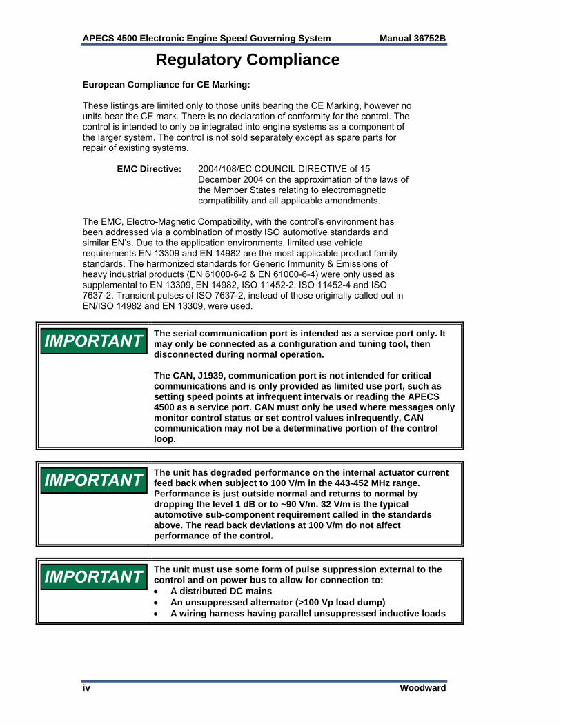
The serial communication port is intended as a service port only. It may only be connected as a configuration and tuning tool, then disconnected during normal operation. The CAN, J1939, communication port is not intended for critical communications and is only provided as limited use port, such as setting speed points at infrequent intervals or reading the APECS 4500 as a service port. CAN must only be used where messages only monitor control status or set control values infrequently, CAN communication may not be a determinative portion of the control loop.
The unit has degraded performance on the internal actuator current feed back when subject to 100 V/m in the 443-452 MHz range. Performance is just outside normal and returns to normal by dropping the level 1 dB or to ~90 V/m. 32 V/m is the typical automotive sub-component requirement called in the standards above. The read back deviations at 100 V/m do not affect performance of the control.
The unit must use some form of pulse suppression external to the control and on power bus to allow for connection to: A distributed DC mains An unsuppressed alternator (>100 Vp load dump) A wiring harness having parallel unsuppressed inductive loads
Manual 36752B APECS 4500 Electronic Engine Speed Governing System
Woodward v
Electrostatic Discharge Awareness All electronic equipment is static-sensitive, some components more than others. To protect these components from static damage, you must take special precautions to minimize or eliminate electrostatic discharges. Follow these precautions when working with or near the control. 1. Before doing maintenance on the electronic control, discharge the static
electricity on your body to ground by touching and holding a grounded metal object (pipes, cabinets, equipment, etc.).
2. Avoid the build-up of static electricity on your body by not wearing clothing
made of synthetic materials. Wear cotton or cotton-blend materials as much as possible because these do not store static electric charges as much as synthetics.
3. Keep plastic, vinyl, and Styrofoam materials (such as plastic or Styrofoam
cups, cup holders, cigarette packages, cellophane wrappers, vinyl books or folders, plastic bottles, and plastic ash trays) away from the control, the modules, and the work area as much as possible.
4. Do not remove the printed circuit board (PCB) from the control cabinet
unless absolutely necessary. If you must remove the PCB from the control cabinet, follow these precautions:
Do not touch any part of the PCB except the edges. Do not touch the electrical conductors, the connectors, or the
components with conductive devices or with your hands. When replacing a PCB, keep the new PCB in the plastic antistatic
protective bag it comes in until you are ready to install it. Immediately after removing the old PCB from the control cabinet, place it in the antistatic protective bag.
To prevent damage to electronic components caused by improper handling, read and observe the precautions in Woodward manual 82715, Guide for Handling and Protection of Electronic Controls, Printed Circuit Boards, and Modules.

APECS 4500 Electronic Engine Speed Governing System Manual 36752B
vi Woodward
Manual 36752B APECS 4500 Electronic Engine Speed Governing System
Woodward 1
Chapter 1. General Information
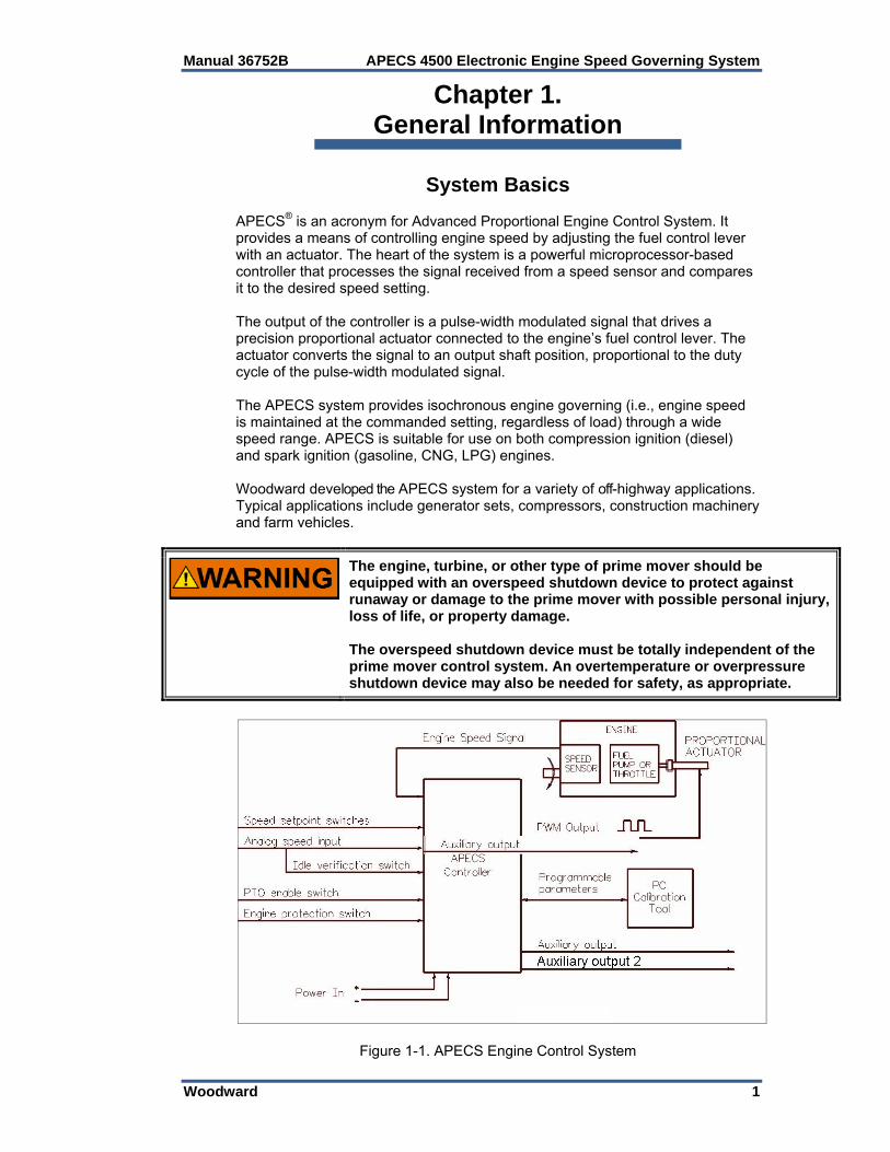
System Basics APECS® is an acronym for Advanced Proportional Engine Control System. It provides a means of controlling engine speed by adjusting the fuel control lever with an actuator. The heart of the system is a powerful microprocessor-based controller that processes the signal received from a speed sensor and compares it to the desired speed setting. The output of the controller is a pulse-width modulated signal that drives a precision proportional actuator connected to the engine’s fuel control lever. The actuator converts the signal to an output shaft position, proportional to the duty cycle of the pulse-width modulated signal. The APECS system provides isochronous engine governing (i.e., engine speed is maintained at the commanded setting, regardless of load) through a wide speed range. APECS is suitable for use on both compression ignition (diesel) and spark ignition (gasoline, CNG, LPG) engines. Woodward developed the APECS system for a variety of off-highway applications. Typical applications include generator sets, compressors, construction machinery and farm vehicles.
The engine, turbine, or other type of prime mover should be equipped with an overspeed shutdown device to protect against runaway or damage to the prime mover with possible personal injury, loss of life, or property damage. The overspeed shutdown device must be totally independent of the prime mover control system. An overtemperature or overpressure shutdown device may also be needed for safety, as appropriate.
Figure 1-1. APECS Engine Control System
APECS 4500 Electronic Engine Speed Governing System Manual 36752B
2 Woodward
Environmental and Electrical Specifications Operating Temperature –40 to +185 °F (–40 to +85 °C) Storage Temperature –40 to +185 °F (–40 to +85 °C) Shock 20 Gs at 45 Hz Vibration (Sinusoidal) 6 Gs from 40 Hz to 2000 Hz Enclosure Protection Deutsch PCB enclosure EEC-325X4B with two 12-way sealed connectors Operating Voltage and Current 9-30 Vdc, reverse polarity protected Electromagnetic Compatibility (EMC) Protection The unit has met the requirements of Automotive style testing:
ISO 13766:2006 ESA, EN/ISO 14982, EN 13309, 30-1000 MHz radiated emissions Limit
IEC 61000-4-2:2001, Operational ESD ±6 kV Contact, ±8 kV Air
ISO 10605:2001(E), Handling ESD ±6 kV Contact to control pins, ±8 kV Air to control pins
ISO 11452-2:2004 Radio Frequency Interference Immunity/Susceptibility *100 VRMS/m Peak Envelope, 200 MHz to 1000 MHz 80% depth 1 kHz AM. Demonstrates will meet EN 61000-6-2 10 V/m requirement.
ISO 11452-4:2005 Bulk Current Injection (BCI) ISO 11452-4:2005 Bulk Current Injection (BCI) 20-200 MHz, 100 mARMS (peak envelop), No modulation and 80% AM at 1 kHz. Demonstrates will meet EN 61000-6-2 10 VRMS requirement.
ISO 7637-2:2004 Pulse 1 –100 Vp to power inputs (more severe pulses clamped externally)
ISO 7637-2:2004 Pulse 2a 50 V to power inputs
ISO 7637-2:2004 Pulse 3a/3b ±250 V to power inputs
ISO 7637-2:2004 Pulse 5a 100 Vp to power inputs
ISO 7637-2:2004 Pulse 5B 54 Vp to power inputs (clamped externally).
* ISO 11452-2: Deviations on actuator current read back, used for gross position error, were observed above 89.5 V/m (100 V/m -1 dB) in the 443-452 MHz range. Since this is a secondary informational function not used in the control loop beyond gross position check, this deviation was deemed acceptable.
Manual 36752B APECS 4500 Electronic Engine Speed Governing System
Woodward 3
The unit has met the requirements of Generic Industrial Emissions/Immunity (CE mark) testing:
EN61000-6-4 CISPR 11 Group 1, Class A radiated emissions
EN 61000-6-2 IEC 61000-4-2 functional ESD IEC 61000-4-4 functional EFT
Adjusted limits of ±250 V based on cable lengths <3 m long & application.
Weight Approx. 0.6 lb (0.27 kg)
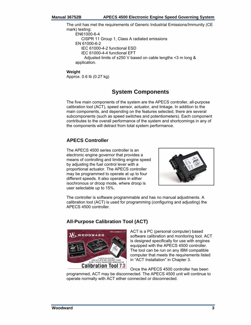
System Components The five main components of the system are the APECS controller, all-purpose calibration tool (ACT), speed sensor, actuator, and linkage. In addition to the main components, and depending on the features selected, there are several subcomponents (such as speed switches and potentiometers). Each component contributes to the overall performance of the system and shortcomings in any of the components will detract from total system performance. APECS Controller The APECS 4500 series controller is an electronic engine governor that provides a means of controlling and limiting engine speed by adjusting the fuel control lever with a proportional actuator. The APECS controller may be programmed to operate at up to four different speeds. It also operates in either isochronous or droop mode, where droop is user selectable up to 15%. The controller is software programmable and has no manual adjustments. A calibration tool (ACT) is used for programming (configuring and adjusting) the APECS 4500 controller. All-Purpose Calibration Tool (ACT)
ACT is a PC (personal computer) based software calibration and monitoring tool. ACT is designed specifically for use with engines equipped with the APECS 4500 controller. The tool can be run on any IBM compatible computer that meets the requirements listed in “ACT Installation” in Chapter 3. Once the APECS 4500 controller has been
programmed, ACT may be disconnected. The APECS 4500 unit will continue to operate normally with ACT either connected or disconnected.

APECS 4500 Electronic Engine Speed Governing System Manual 36752B
4 Woodward
Speed Sensor APECS 4500 monitors engine speed continuously. Engine speed may be sensed by monitoring the frequency of spark events in spark-ignition engines or through the use of a sensor that detects the passing of teeth on an engine driven gear (e.g., flywheel). The universal speed input of the APECS 4500 is compatible with the following types of speed input signal: Magnetic Pickup. Magnetic pickups are available from Woodward Coil-type Spark Ignition. Speed can be sensed from the negative side of the
coil primary winding. Magneto Spark Ignition. Speed can be sensed from the spark kill wire on the
primary winding, but will not work if a diode is placed between the magneto and the APECS input (may be found on some multi-cylinder engines with magneto ignitions.
Hall-Effect Sensor Actuator The actuator converts a pulse-width modulated signal received from the controller to an output shaft position proportional to the duty cycle of the pulse-width modulated signal. The actuator is mounted on the engine and connected to the control lever by a mechanical linkage.
On spark ignition engines, the control lever is usually the throttle lever. On compression ignition engines (diesels), the control lever is usually one of the mechanical governor levers (either shutoff or governor).
Linkage The linkage connects the actuator shaft to the engine control lever. A good linkage allows for misalignments and contributes to accurate, stable and responsive performance with minimal play or friction.
The scope of this manual does not include selection and installation of speed sensors, actuators, or linkages that Woodward offers for use with the APECS system. Information is available on our website at www.woodward.com.
The need for sub-components such as switches and potentiometers is application dependent. Please contact Woodward for information specific to your application.
Manual 36752B APECS 4500 Electronic Engine Speed Governing System
Woodward 5
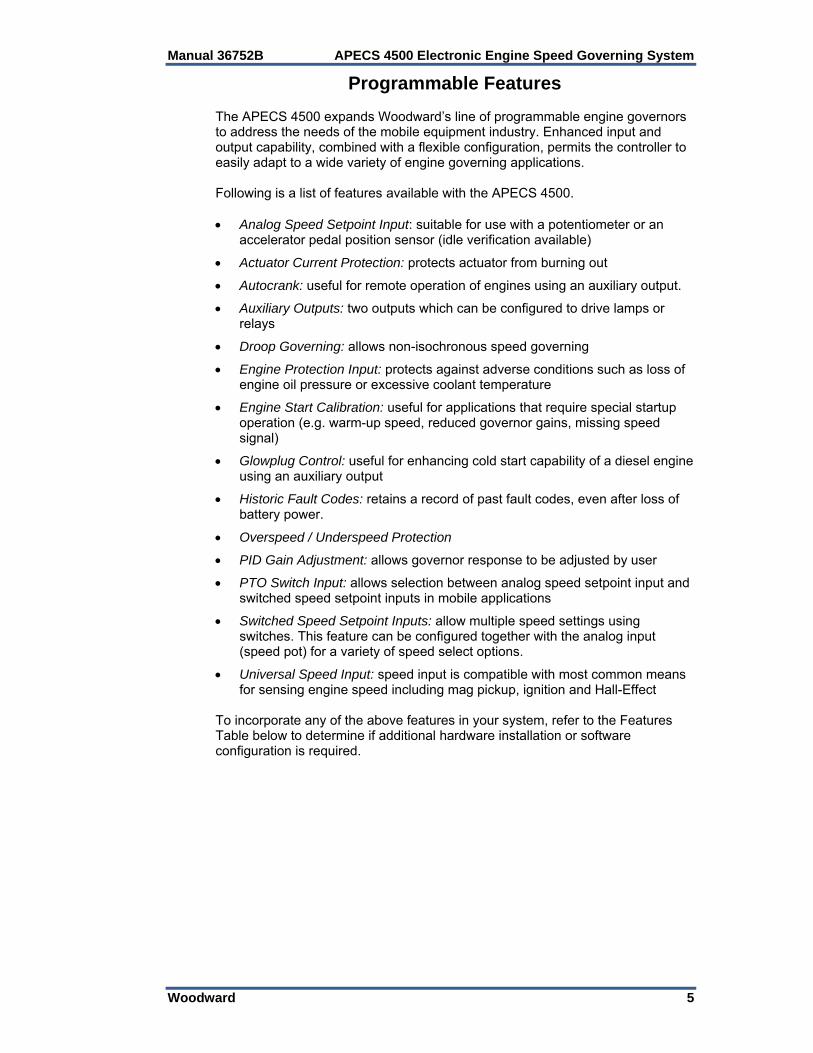
Programmable Features The APECS 4500 expands Woodward’s line of programmable engine governors to address the needs of the mobile equipment industry. Enhanced input and output capability, combined with a flexible configuration, permits the controller to easily adapt to a wide variety of engine governing applications. Following is a list of features available with the APECS 4500. Analog Speed Setpoint Input: suitable for use with a potentiometer or an
accelerator pedal position sensor (idle verification available)
Actuator Current Protection: protects actuator from burning out
Autocrank: useful for remote operation of engines using an auxiliary output.
Auxiliary Outputs: two outputs which can be configured to drive lamps or relays
Droop Governing: allows non-isochronous speed governing
Engine Protection Input: protects against adverse conditions such as loss of engine oil pressure or excessive coolant temperature
Engine Start Calibration: useful for applications that require special startup operation (e.g. warm-up speed, reduced governor gains, missing speed signal)
Glowplug Control: useful for enhancing cold start capability of a diesel engine using an auxiliary output
Historic Fault Codes: retains a record of past fault codes, even after loss of battery power.
Overspeed / Underspeed Protection
PID Gain Adjustment: allows governor response to be adjusted by user
PTO Switch Input: allows selection between analog speed setpoint input and switched speed setpoint inputs in mobile applications
Switched Speed Setpoint Inputs: allow multiple speed settings using switches. This feature can be configured together with the analog input (speed pot) for a variety of speed select options.
Universal Speed Input: speed input is compatible with most common means for sensing engine speed including mag pickup, ignition and Hall-Effect
To incorporate any of the above features in your system, refer to the Features Table below to determine if additional hardware installation or software configuration is required.
APECS 4500 Electronic Engine Speed Governing System Manual 36752B
6 Woodward
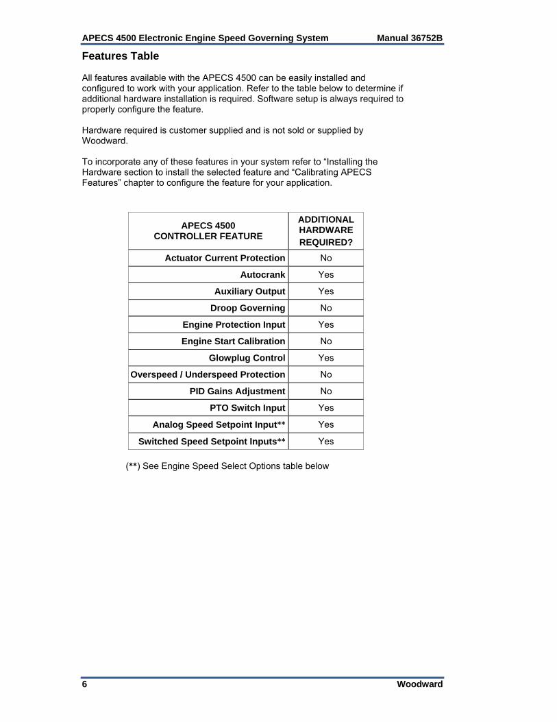
Features Table All features available with the APECS 4500 can be easily installed and configured to work with your application. Refer to the table below to determine if additional hardware installation is required. Software setup is always required to properly configure the feature. Hardware required is customer supplied and is not sold or supplied by Woodward. To incorporate any of these features in your system refer to “Installing the Hardware section to install the selected feature and “Calibrating APECS Features” chapter to configure the feature for your application.
(**) See Engine Speed Select Options table below
APECS 4500 CONTROLLER FEATURE
ADDITIONAL HARDWARE REQUIRED?
Actuator Current Protection No
Autocrank Yes
Auxiliary Output Yes
Droop Governing No
Engine Protection Input Yes
Engine Start Calibration No
Glowplug Control Yes
Overspeed / Underspeed Protection No
PID Gains Adjustment No
PTO Switch Input Yes
Analog Speed Setpoint Input** Yes
Switched Speed Setpoint Inputs** Yes
Manual 36752B APECS 4500 Electronic Engine Speed Governing System
Woodward 7
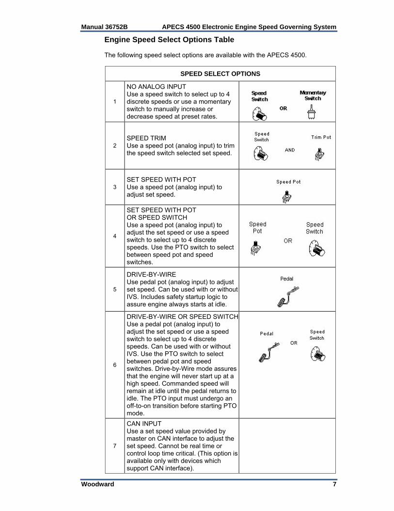
Engine Speed Select Options Table The following speed select options are available with the APECS 4500.
SPEED SELECT OPTIONS
1
NO ANALOG INPUT Use a speed switch to select up to 4 discrete speeds or use a momentary switch to manually increase or decrease speed at preset rates.
2 SPEED TRIM Use a speed pot (analog input) to trim the speed switch selected set speed.
3 SET SPEED WITH POT Use a speed pot (analog input) to adjust set speed.
4
SET SPEED WITH POT OR SPEED SWITCH Use a speed pot (analog input) to adjust the set speed or use a speed switch to select up to 4 discrete speeds. Use the PTO switch to select between speed pot and speed switches.
5
DRIVE-BY-WIRE Use pedal pot (analog input) to adjust set speed. Can be used with or without IVS. Includes safety startup logic to assure engine always starts at idle.
6
DRIVE-BY-WIRE OR SPEED SWITCHUse a pedal pot (analog input) to adjust the set speed or use a speed switch to select up to 4 discrete speeds. Can be used with or without IVS. Use the PTO switch to select between pedal pot and speed switches. Drive-by-Wire mode assures that the engine will never start up at a high speed. Commanded speed will remain at idle until the pedal returns to idle. The PTO input must undergo an off-to-on transition before starting PTO mode.
7
CAN INPUT Use a set speed value provided by master on CAN interface to adjust the set speed. Cannot be real time or control loop time critical. (This option is available only with devices which support CAN interface).

APECS 4500 Electronic Engine Speed Governing System Manual 36752B
8 Woodward
Chapter 2. Installing the Hardware
Introduction This chapter provides the general information for mounting location selection, installation, and wiring of the APECS® 4500 control. Hardware dimensions, ratings, and requirements are given for mounting and wiring the control. When installing the APECS hardware, be aware that some of the options selected may also require hardware setup (see list below). Hardware required for optional features is not provided or sold by Woodward. Take adequate protection to ensure personal and equipment safety and follow the suggested installation sequence given below: Install main components:
Wiring page 8 Speed Sensor page 14 Actuator & Linkage page 15 Install optional components (hardware installation required):
Engine Speed Setpoint—Analog Input page 16 Engine Speed Setpoint—Switched Inputs page 17 Power Take-off Input page 19 Glowplug page 20 Autocrank page 21 Auxiliary Output page 21 Engine Protection Input page 22 CAN Communication page 23
Wiring Guidelines APECS 4500 has two 12-pin Deutsch connectors labeled J1 (grey) and J2 (black). Mating connectors may be purchased from Woodward (part number SA-4490) or from a Deutsch distributor. Deutsch part numbers are as follows: J1 (Grey): DTM06-12SA J2 (Black): DTM06-12SB Sockets (pins, 12 per connector): 1062-20-0122 Wedgelocks (1 per connector): WM-12S Blank Pins (to fill empty pins): 0413-204-2005 Always use an appropriate crimping tool for attaching the pins to the wiring harness. Pay close attention to the pin numbers embossed on each connector.
Manual 36752B APECS 4500 Electronic Engine Speed Governing System
Woodward 9
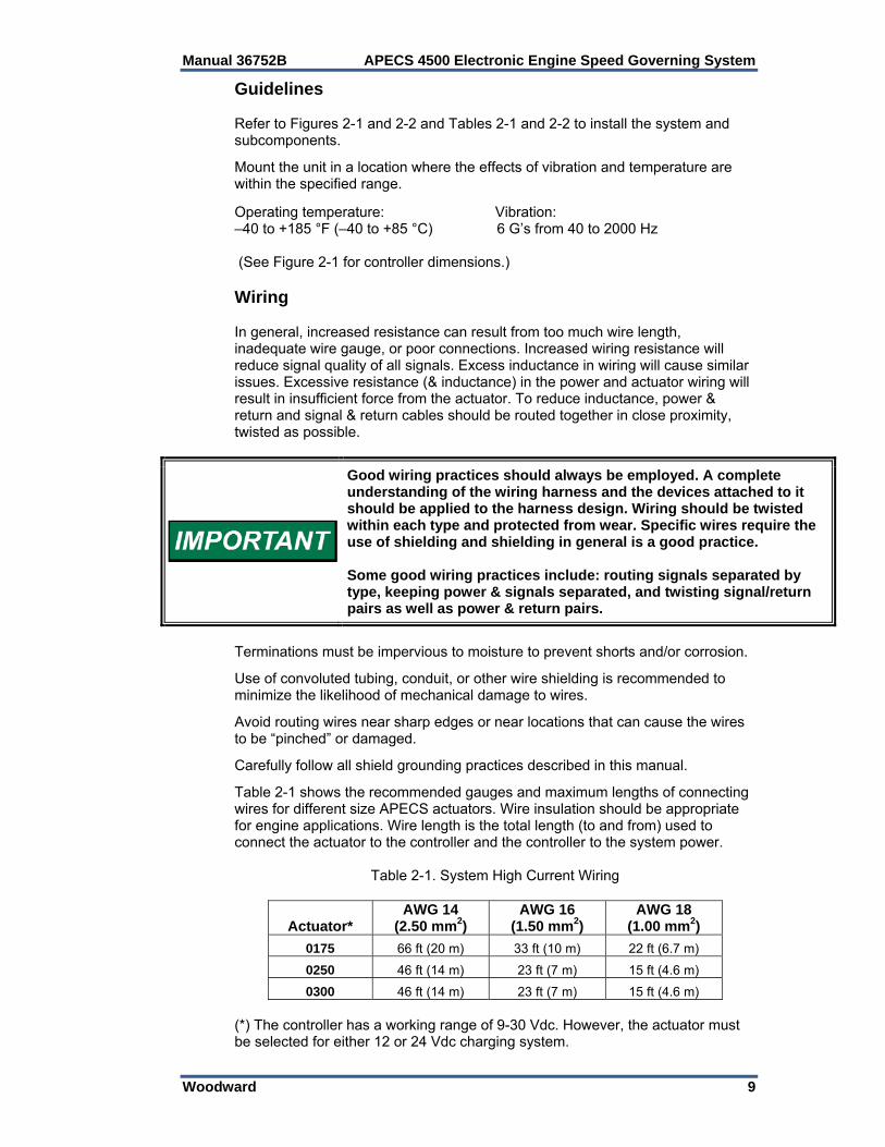
Guidelines Refer to Figures 2-1 and 2-2 and Tables 2-1 and 2-2 to install the system and subcomponents. Mount the unit in a location where the effects of vibration and temperature are within the specified range.
Operating temperature: Vibration: –40 to +185 °F (–40 to +85 °C) 6 G’s from 40 to 2000 Hz (See Figure 2-1 for controller dimensions.) Wiring In general, increased resistance can result from too much wire length, inadequate wire gauge, or poor connections. Increased wiring resistance will reduce signal quality of all signals. Excess inductance in wiring will cause similar issues. Excessive resistance (& inductance) in the power and actuator wiring will result in insufficient force from the actuator. To reduce inductance, power & return and signal & return cables should be routed together in close proximity, twisted as possible.
Good wiring practices should always be employed. A complete understanding of the wiring harness and the devices attached to it should be applied to the harness design. Wiring should be twisted within each type and protected from wear. Specific wires require the use of shielding and shielding in general is a good practice. Some good wiring practices include: routing signals separated by type, keeping power & signals separated, and twisting signal/return pairs as well as power & return pairs.
Terminations must be impervious to moisture to prevent shorts and/or corrosion. Use of convoluted tubing, conduit, or other wire shielding is recommended to minimize the likelihood of mechanical damage to wires. Avoid routing wires near sharp edges or near locations that can cause the wires to be “pinched” or damaged. Carefully follow all shield grounding practices described in this manual. Table 2-1 shows the recommended gauges and maximum lengths of connecting wires for different size APECS actuators. Wire insulation should be appropriate for engine applications. Wire length is the total length (to and from) used to connect the actuator to the controller and the controller to the system power.
Table 2-1. System High Current Wiring
Actuator* AWG 14
(2.50 mm2) AWG 16
(1.50 mm2) AWG 18
(1.00 mm2)
0175 66 ft (20 m) 33 ft (10 m) 22 ft (6.7 m)
0250 46 ft (14 m) 23 ft (7 m) 15 ft (4.6 m)
0300 46 ft (14 m) 23 ft (7 m) 15 ft (4.6 m) (*) The controller has a working range of 9-30 Vdc. However, the actuator must be selected for either 12 or 24 Vdc charging system.
APECS 4500 Electronic Engine Speed Governing System Manual 36752B
10 Woodward
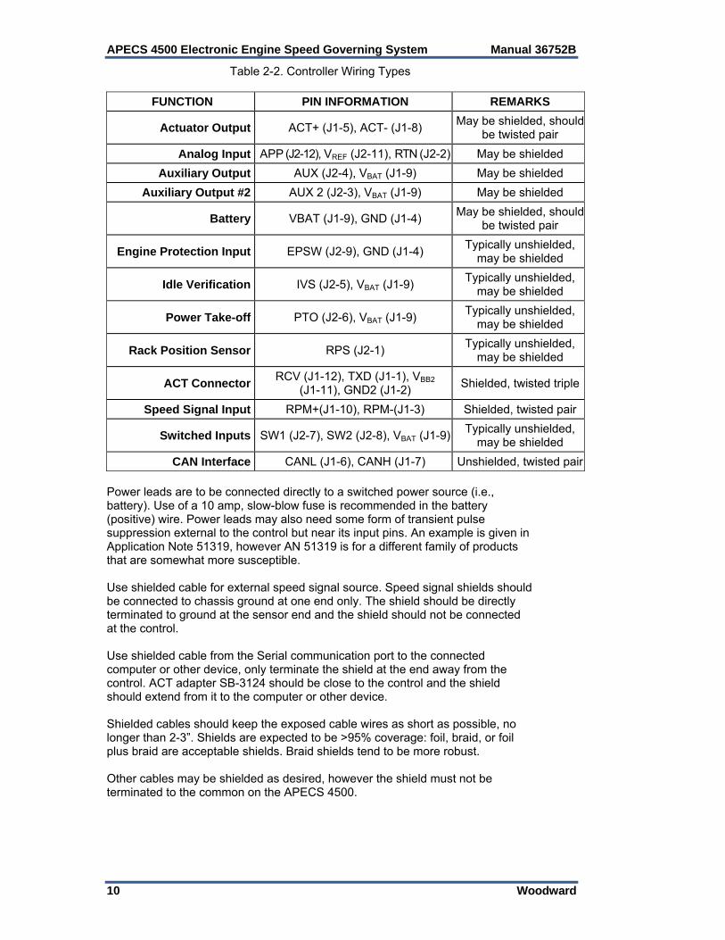
Table 2-2. Controller Wiring Types
FUNCTION PIN INFORMATION REMARKS
Actuator Output ACT+ (J1-5), ACT- (J1-8) May be shielded, should
be twisted pair
Analog Input APP (J2-12), VREF (J2-11), RTN (J2-2) May be shielded
Auxiliary Output AUX (J2-4), VBAT (J1-9) May be shielded
Auxiliary Output #2 AUX 2 (J2-3), VBAT (J1-9) May be shielded
Battery VBAT (J1-9), GND (J1-4) May be shielded, should
be twisted pair
Engine Protection Input EPSW (J2-9), GND (J1-4) Typically unshielded,
may be shielded
Idle Verification IVS (J2-5), VBAT (J1-9) Typically unshielded,
may be shielded
Power Take-off PTO (J2-6), VBAT (J1-9) Typically unshielded,
may be shielded
Rack Position Sensor RPS (J2-1) Typically unshielded,
may be shielded
ACT Connector RCV (J1-12), TXD (J1-1), VBB2
(J1-11), GND2 (J1-2) Shielded, twisted triple
Speed Signal Input RPM+(J1-10), RPM-(J1-3) Shielded, twisted pair
Switched Inputs SW1 (J2-7), SW2 (J2-8), VBAT (J1-9)Typically unshielded,
may be shielded
CAN Interface CANL (J1-6), CANH (J1-7) Unshielded, twisted pair
Power leads are to be connected directly to a switched power source (i.e., battery). Use of a 10 amp, slow-blow fuse is recommended in the battery (positive) wire. Power leads may also need some form of transient pulse suppression external to the control but near its input pins. An example is given in Application Note 51319, however AN 51319 is for a different family of products that are somewhat more susceptible. Use shielded cable for external speed signal source. Speed signal shields should be connected to chassis ground at one end only. The shield should be directly terminated to ground at the sensor end and the shield should not be connected at the control. Use shielded cable from the Serial communication port to the connected computer or other device, only terminate the shield at the end away from the control. ACT adapter SB-3124 should be close to the control and the shield should extend from it to the computer or other device. Shielded cables should keep the exposed cable wires as short as possible, no longer than 2-3”. Shields are expected to be >95% coverage: foil, braid, or foil plus braid are acceptable shields. Braid shields tend to be more robust. Other cables may be shielded as desired, however the shield must not be terminated to the common on the APECS 4500.

Manual 36752B APECS 4500 Electronic Engine Speed Governing System
Woodward 11
Controller Installation Controller Wiring The controller can be installed in the engine compartment (maximum temperature 185 °F / 85 °C.)
Figure 2-1. APECS 4500 Dimensions
APECS 4500 Electronic Engine Speed Governing System Manual 36752B
12 Woodward
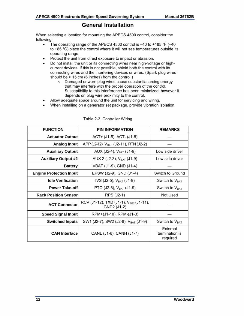
General Installation When selecting a location for mounting the APECS 4500 control, consider the following:
The operating range of the APECS 4500 control is –40 to +185 °F (–40 to +85 °C) place the control where it will not see temperatures outside its operating range.
Protect the unit from direct exposure to impact or abrasion. Do not install the unit or its connecting wires near high-voltage or high-
current devices. If this is not possible, shield both the control with its connecting wires and the interfering devices or wires. (Spark plug wires should be > 15 cm (6 inches) from the control.)
o Damaged or worn plug wires cause substantial arcing energy that may interfere with the proper operation of the control. Susceptibility to this interference has been minimized; however it depends on plug wire proximity to the control.
Allow adequate space around the unit for servicing and wiring. When installing on a generator set package, provide vibration isolation.
Table 2-3. Controller Wiring
FUNCTION PIN INFORMATION REMARKS
Actuator Output ACT+ (J1-5), ACT- (J1-8) —
Analog Input APP (J2-12), VREF (J2-11), RTN (J2-2) —
Auxiliary Output AUX (J2-4), VBAT (J1-9) Low side driver
Auxiliary Output #2 AUX 2 (J2-3), VBAT (J1-9) Low side driver
Battery VBAT (J1-9), GND (J1-4) —
Engine Protection Input EPSW (J2-9), GND (J1-4) Switch to Ground
Idle Verification IVS (J2-5), VBAT (J1-9) Switch to VBAT
Power Take-off PTO (J2-6), VBAT (J1-9) Switch to VBAT
Rack Position Sensor RPS (J2-1) Not Used
ACT Connector RCV (J1-12), TXD (J1-1), VBB2 (J1-11),
GND2 (J1-2) —
Speed Signal Input RPM+(J1-10), RPM-(J1-3) —
Switched Inputs SW1 (J2-7), SW2 (J2-8), VBAT (J1-9) Switch to VBAT
CAN Interface CANL (J1-6), CANH (J1-7) External
termination is required

Manual 36752B APECS 4500 Electronic Engine Speed Governing System
Woodward 13
Controller Pinout Use the diagram below to connect your APECS controller to ACT, your preferred speed sensor, and various inputs and outputs.
Figure 2-2. APECS 4500 Wiring Diagram
APECS 4500 Electronic Engine Speed Governing System Manual 36752B
14 Woodward
Speed Sensor Installation Guidelines There are four different speed-sensing devices that can be used with the APECS 4500 system.
Magnetic pickup Spark ignition Magneto Hall Effect sensor
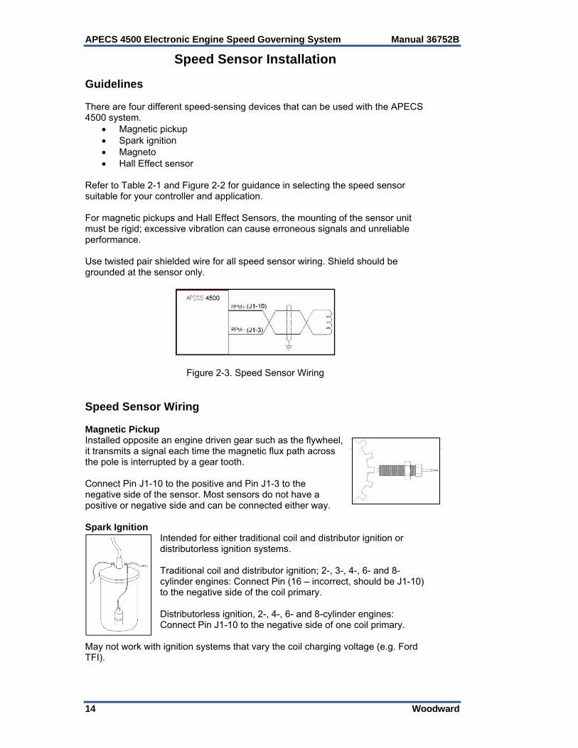
Refer to Table 2-1 and Figure 2-2 for guidance in selecting the speed sensor suitable for your controller and application. For magnetic pickups and Hall Effect Sensors, the mounting of the sensor unit must be rigid; excessive vibration can cause erroneous signals and unreliable performance. Use twisted pair shielded wire for all speed sensor wiring. Shield should be grounded at the sensor only.
Figure 2-3. Speed Sensor Wiring Speed Sensor Wiring Magnetic Pickup Installed opposite an engine driven gear such as the flywheel, it transmits a signal each time the magnetic flux path across the pole is interrupted by a gear tooth. Connect Pin J1-10 to the positive and Pin J1-3 to the negative side of the sensor. Most sensors do not have a positive or negative side and can be connected either way. Spark Ignition
Intended for either traditional coil and distributor ignition or distributorless ignition systems. Traditional coil and distributor ignition; 2-, 3-, 4-, 6- and 8-cylinder engines: Connect Pin (16 – incorrect, should be J1-10) to the negative side of the coil primary. Distributorless ignition, 2-, 4-, 6- and 8-cylinder engines: Connect Pin J1-10 to the negative side of one coil primary.
May not work with ignition systems that vary the coil charging voltage (e.g. Ford TFI).
Manual 36752B APECS 4500 Electronic Engine Speed Governing System
Woodward 15
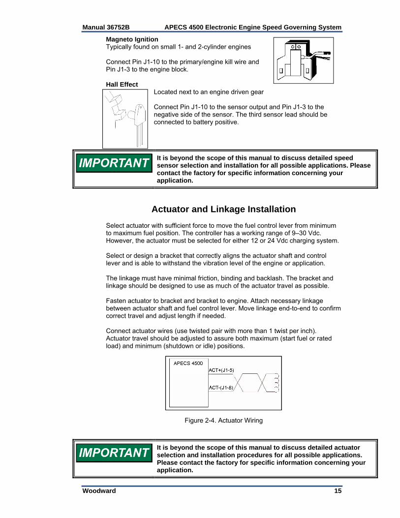
Magneto Ignition Typically found on small 1- and 2-cylinder engines Connect Pin J1-10 to the primary/engine kill wire and Pin J1-3 to the engine block. Hall Effect
Located next to an engine driven gear Connect Pin J1-10 to the sensor output and Pin J1-3 to the negative side of the sensor. The third sensor lead should be connected to battery positive.
It is beyond the scope of this manual to discuss detailed speed sensor selection and installation for all possible applications. Please contact the factory for specific information concerning your application.
Actuator and Linkage Installation Select actuator with sufficient force to move the fuel control lever from minimum to maximum fuel position. The controller has a working range of 9–30 Vdc. However, the actuator must be selected for either 12 or 24 Vdc charging system. Select or design a bracket that correctly aligns the actuator shaft and control lever and is able to withstand the vibration level of the engine or application. The linkage must have minimal friction, binding and backlash. The bracket and linkage should be designed to use as much of the actuator travel as possible. Fasten actuator to bracket and bracket to engine. Attach necessary linkage between actuator shaft and fuel control lever. Move linkage end-to-end to confirm correct travel and adjust length if needed. Connect actuator wires (use twisted pair with more than 1 twist per inch). Actuator travel should be adjusted to assure both maximum (start fuel or rated load) and minimum (shutdown or idle) positions.
Figure 2-4. Actuator Wiring
It is beyond the scope of this manual to discuss detailed actuator selection and installation procedures for all possible applications. Please contact the factory for specific information concerning your application.

APECS 4500 Electronic Engine Speed Governing System Manual 36752B
16 Woodward
The unit has degraded performance on the internal actuator current feed back when subject to 100 V/m in the 443-452 MHz range. Performance is just outside normal and returns to normal by dropping the level 1 dB or to ~90 V/m. 32 V/m is the typical automotive sub-component requirement called in the standards above. The read back deviations at 100 V/m do not affect performance of the control.
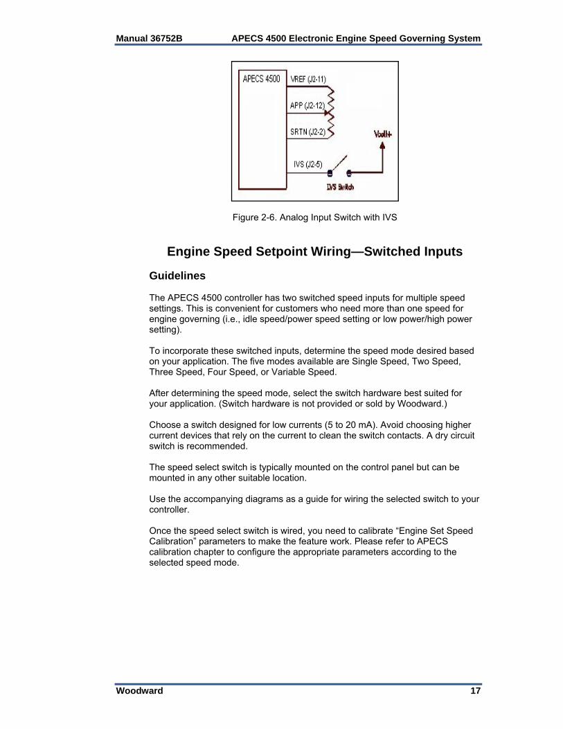
Engine Speed Setpoint Wiring—Analog Input Guidelines The APECS 4500 controller features an analog speed input for mobile or stationary applications. To incorporate this feature, wire the analog input to an external pot (which must be connected to a pedal). Use Figures 6 & 7 as a guide to wire the input to your application. Potentiometer resistances of 3–5 kΩ are recommended. Once the analog speed input is wired, refer to the APECS Calibration section to configure the appropriate parameters. If use of an idle verification switch (IVS) is desired, hook up Pin J2-5 from the controller to the idle verification switch on the pedal. (Refer to the manufacturer’s instructions or OEM manual.) The other side of the switch should be connected to battery voltage (see Figure 2-6). During engine operation, if the IVS switch and pedal pot do not agree, the engine will operate at 10% of actual position of the pedal. Non-potentiometric analog voltages may also be used to command set speed. The analog voltage (0-5 volt max.) should be wired across terminals J2-12 (positive) and J1-4 (ground).
Figure 2-5. Analog Input Switch
Manual 36752B APECS 4500 Electronic Engine Speed Governing System
Woodward 17
Figure 2-6. Analog Input Switch with IVS
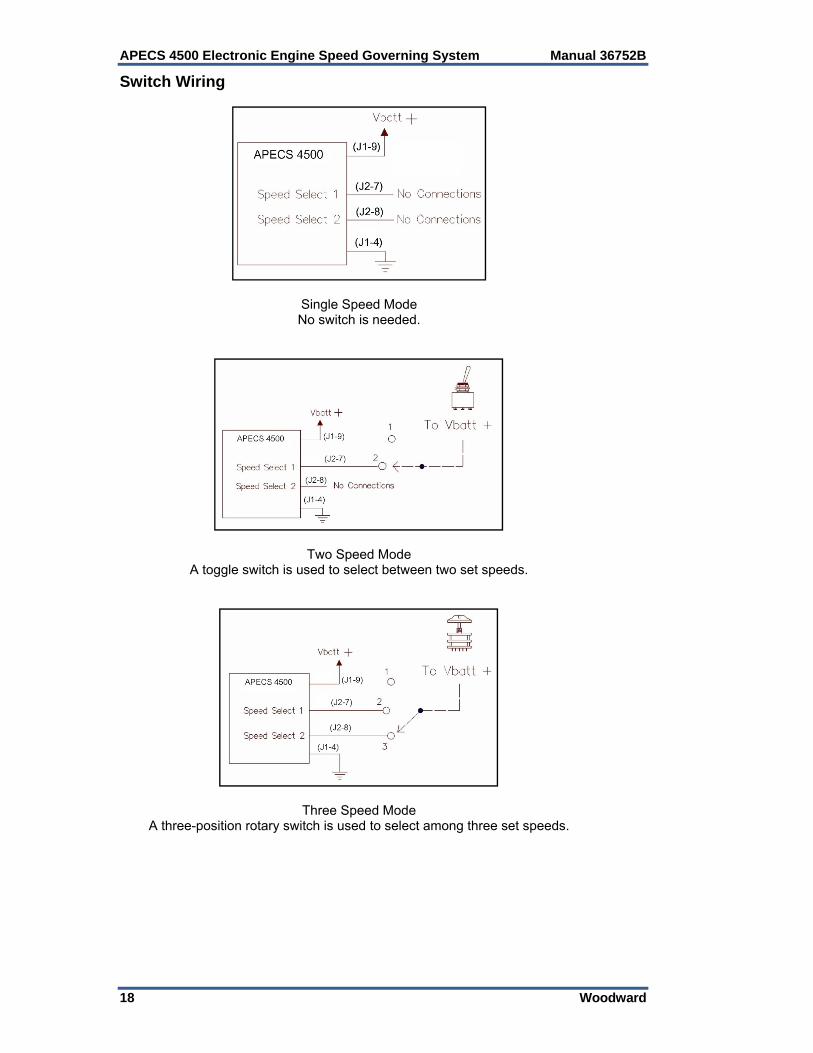
Engine Speed Setpoint Wiring—Switched Inputs Guidelines The APECS 4500 controller has two switched speed inputs for multiple speed settings. This is convenient for customers who need more than one speed for engine governing (i.e., idle speed/power speed setting or low power/high power setting). To incorporate these switched inputs, determine the speed mode desired based on your application. The five modes available are Single Speed, Two Speed, Three Speed, Four Speed, or Variable Speed. After determining the speed mode, select the switch hardware best suited for your application. (Switch hardware is not provided or sold by Woodward.) Choose a switch designed for low currents (5 to 20 mA). Avoid choosing higher current devices that rely on the current to clean the switch contacts. A dry circuit switch is recommended. The speed select switch is typically mounted on the control panel but can be mounted in any other suitable location. Use the accompanying diagrams as a guide for wiring the selected switch to your controller. Once the speed select switch is wired, you need to calibrate “Engine Set Speed Calibration” parameters to make the feature work. Please refer to APECS calibration chapter to configure the appropriate parameters according to the selected speed mode.
APECS 4500 Electronic Engine Speed Governing System Manual 36752B
18 Woodward
Switch Wiring
Single Speed Mode No switch is needed.
Two Speed Mode A toggle switch is used to select between two set speeds.
Three Speed Mode A three-position rotary switch is used to select among three set speeds.
Manual 36752B APECS 4500 Electronic Engine Speed Governing System
Woodward 19
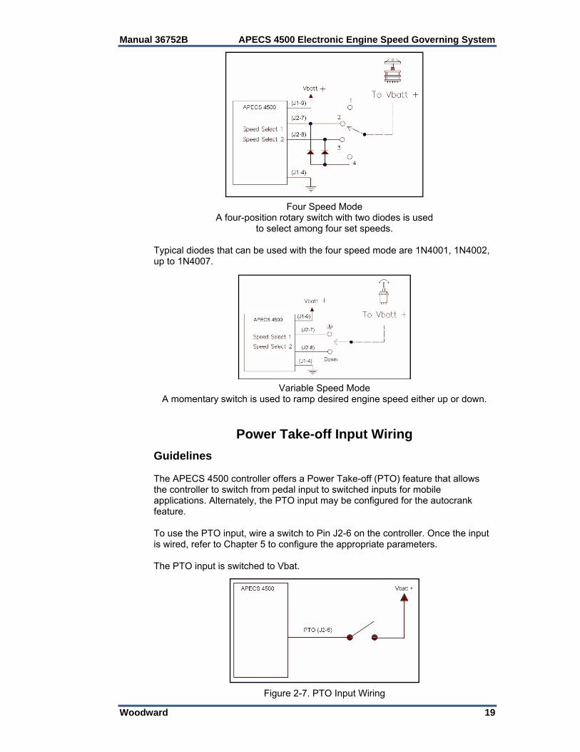
Four Speed Mode
A four-position rotary switch with two diodes is used to select among four set speeds.
Typical diodes that can be used with the four speed mode are 1N4001, 1N4002, up to 1N4007.
Variable Speed Mode
A momentary switch is used to ramp desired engine speed either up or down.
Power Take-off Input Wiring Guidelines The APECS 4500 controller offers a Power Take-off (PTO) feature that allows the controller to switch from pedal input to switched inputs for mobile applications. Alternately, the PTO input may be configured for the autocrank feature. To use the PTO input, wire a switch to Pin J2-6 on the controller. Once the input is wired, refer to Chapter 5 to configure the appropriate parameters. The PTO input is switched to Vbat.
Figure 2-7. PTO Input Wiring
APECS 4500 Electronic Engine Speed Governing System Manual 36752B
20 Woodward
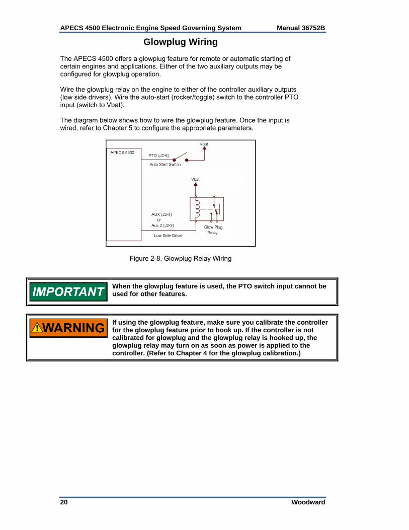
Glowplug Wiring The APECS 4500 offers a glowplug feature for remote or automatic starting of certain engines and applications. Either of the two auxiliary outputs may be configured for glowplug operation. Wire the glowplug relay on the engine to either of the controller auxiliary outputs (low side drivers). Wire the auto-start (rocker/toggle) switch to the controller PTO input (switch to Vbat). The diagram below shows how to wire the glowplug feature. Once the input is wired, refer to Chapter 5 to configure the appropriate parameters.
Figure 2-8. Glowplug Relay Wiring
When the glowplug feature is used, the PTO switch input cannot be used for other features.
If using the glowplug feature, make sure you calibrate the controller for the glowplug feature prior to hook up. If the controller is not calibrated for glowplug and the glowplug relay is hooked up, the glowplug relay may turn on as soon as power is applied to the controller. (Refer to Chapter 4 for the glowplug calibration.)
Manual 36752B APECS 4500 Electronic Engine Speed Governing System
Woodward 21
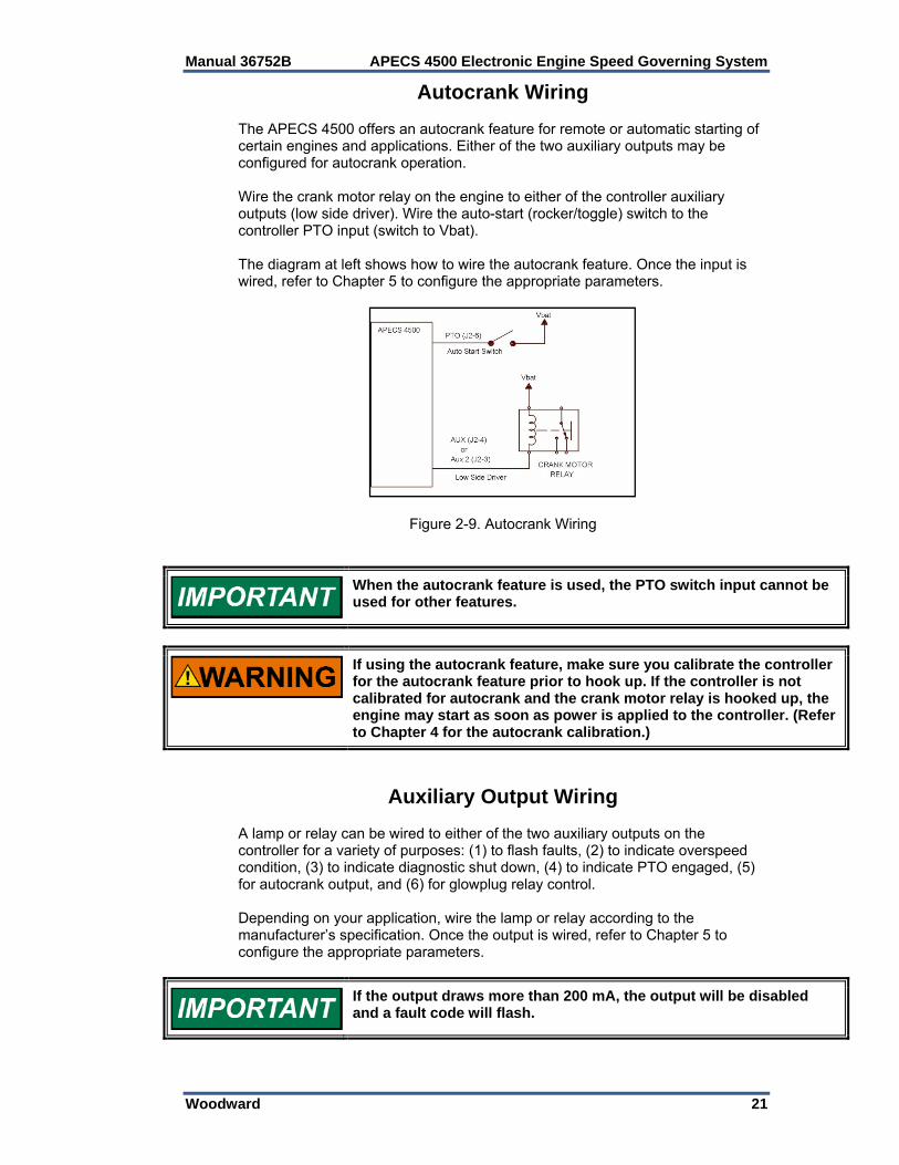
Autocrank Wiring The APECS 4500 offers an autocrank feature for remote or automatic starting of certain engines and applications. Either of the two auxiliary outputs may be configured for autocrank operation. Wire the crank motor relay on the engine to either of the controller auxiliary outputs (low side driver). Wire the auto-start (rocker/toggle) switch to the controller PTO input (switch to Vbat). The diagram at left shows how to wire the autocrank feature. Once the input is wired, refer to Chapter 5 to configure the appropriate parameters.
Figure 2-9. Autocrank Wiring
When the autocrank feature is used, the PTO switch input cannot be used for other features.
If using the autocrank feature, make sure you calibrate the controller for the autocrank feature prior to hook up. If the controller is not calibrated for autocrank and the crank motor relay is hooked up, the engine may start as soon as power is applied to the controller. (Refer to Chapter 4 for the autocrank calibration.)
Auxiliary Output Wiring A lamp or relay can be wired to either of the two auxiliary outputs on the controller for a variety of purposes: (1) to flash faults, (2) to indicate overspeed condition, (3) to indicate diagnostic shut down, (4) to indicate PTO engaged, (5) for autocrank output, and (6) for glowplug relay control. Depending on your application, wire the lamp or relay according to the manufacturer’s specification. Once the output is wired, refer to Chapter 5 to configure the appropriate parameters.
If the output draws more than 200 mA, the output will be disabled and a fault code will flash.
APECS 4500 Electronic Engine Speed Governing System Manual 36752B
22 Woodward
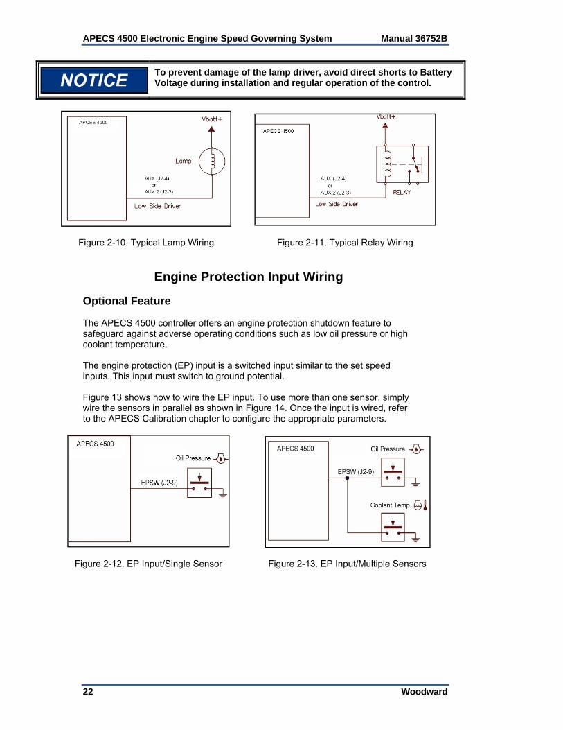
To prevent damage of the lamp driver, avoid direct shorts to Battery Voltage during installation and regular operation of the control.
Figure 2-10. Typical Lamp Wiring
Figure 2-11. Typical Relay Wiring
Engine Protection Input Wiring Optional Feature The APECS 4500 controller offers an engine protection shutdown feature to safeguard against adverse operating conditions such as low oil pressure or high coolant temperature. The engine protection (EP) input is a switched input similar to the set speed inputs. This input must switch to ground potential. Figure 13 shows how to wire the EP input. To use more than one sensor, simply wire the sensors in parallel as shown in Figure 14. Once the input is wired, refer to the APECS Calibration chapter to configure the appropriate parameters.
Figure 2-12. EP Input/Single Sensor
Figure 2-13. EP Input/Multiple Sensors
Manual 36752B APECS 4500 Electronic Engine Speed Governing System
Woodward 23
CAN Communication Wiring Optional Feature The APECS 4500 controller offers an optional J1939 CAN communication feature to allow remote updates of speed settings and reading the control status. CAN communications require the use of appropriately rated cable and each end of the communication bus to be terminated with 120 Ohms from CANH to CANL. This control does not expect a shielded CAN cable, but if one is used, DO NOT terminate the shield to the Control common. If present, the CAN cable shield should be grounded to chassis at one point in the network and may have AC connections at various devices, EXCEPT at the APECS 4500 control. CAN communication wiring must be routed away from all sources of spark such as spark wiring, relays, and similar devices.
The CAN, J1939, communication port is not intended for critical communications and is only provided as limited use port, such as setting speed points at infrequent intervals or reading the APECS 4500 as a service port. CAN must only be used where messages only monitor control status or set control values infrequently, CAN communication may not be a determinative portion of the control loop.

APECS 4500 Electronic Engine Speed Governing System Manual 36752B
24 Woodward
Chapter 3. ACT Operation
ACT Installation Description The All Purpose Calibration Tool (ACT) is used for programming (configuring and adjusting) and monitoring the APECS controller with your personal computer. The ACT software resides on a PC and communicates to the APECS 4500 controller through J1 connector. The ACT Kit (Woodward part number SA-4488) is required to make communications possible. The ACT Kit contains the following:
Interface module Calibration tool interface RS-232 connecting cable
Set-up Requirements Hardware Requirements
PC-compatible laptop or desktop computer with at least one available serial communications port, and Windows 95/98/ME/2000/XP/Vista as the operating system [Note that ACT has not been completely tested and verified under Vista.]
64 MB of available RAM memory and hard disk with at least 4 MB of free disk space
SVGA capable video card and monitor, capable of 256 colors and 800 x 600 display
Software Requirements
APECS Calibration Tool (Woodward P/N 5418-2570) ACT software can be downloaded and installed from the Woodward
website (www.woodward.com/software).
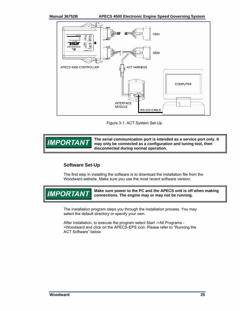
Hardware Set-up To connect your PC to the APECS 4500 unit, an RS-232 connecting cable with proprietary interface module and calibration tool interface is required.
Make sure power to the PC and the APECS unit is off when making connections. The engine may or may not be running.
Connect one end of the RS-232 cable to your PC’s COM port. Connect the other end of the cable to the interface module. Now connect the interface module to the APECS 4500 unit via the connector on the harness. The interface harness is inserted between the J1 (grey) connector of the controller and the mating connector in the user’s wiring harness. If your PC is not equipped with a COM port you may need to use USB to RS-232 converter. Woodward recommends the following converters:
USB 1.1 to RS-232 Converter (Woodward P/N 1249-1175) USB 2.0 to RS-232 Converter (Woodward P/N 1249-1176)
Manual 36752B APECS 4500 Electronic Engine Speed Governing System
Woodward 25
Figure 3-1. ACT System Set-Up
The serial communication port is intended as a service port only. It may only be connected as a configuration and tuning tool, then disconnected during normal operation.
Software Set-Up The first step in installing the software is to download the installation file from the Woodward website. Make sure you use the most recent software version.
Make sure power to the PC and the APECS unit is off when making connections. The engine may or may not be running.
The installation program steps you through the installation process. You may select the default directory or specify your own. After installation, to execute the program select Start ->All Programs ->Woodward and click on the APECS-EPS icon. Please refer to “Running the ACT Software” below.
APECS 4500 Electronic Engine Speed Governing System Manual 36752B
26 Woodward
Basic ACT Operation Running the ACT Software The ACT software is fairly easy to use. Follow the procedures below to run the program. 1. Make certain that the APECS
controller is powered up and connected to the computer’s COM port.
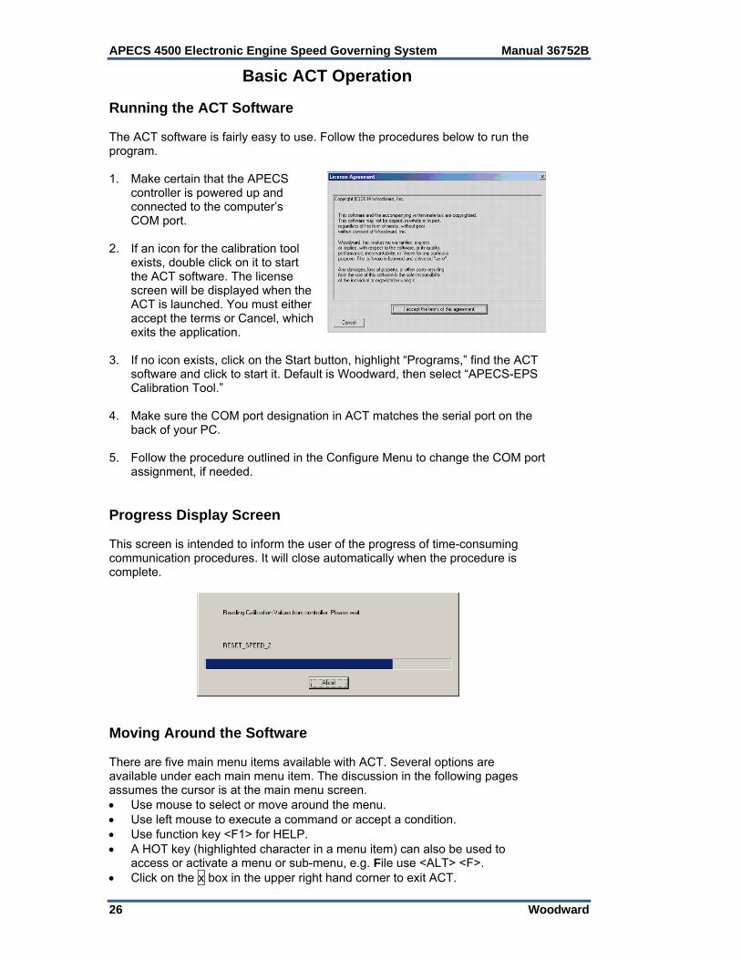
2. If an icon for the calibration tool
exists, double click on it to start the ACT software. The license screen will be displayed when the ACT is launched. You must either accept the terms or Cancel, which exits the application.
3. If no icon exists, click on the Start button, highlight “Programs,” find the ACT
software and click to start it. Default is Woodward, then select “APECS-EPS Calibration Tool.”
4. Make sure the COM port designation in ACT matches the serial port on the
back of your PC. 5. Follow the procedure outlined in the Configure Menu to change the COM port
assignment, if needed. Progress Display Screen This screen is intended to inform the user of the progress of time-consuming communication procedures. It will close automatically when the procedure is complete.
Moving Around the Software There are five main menu items available with ACT. Several options are available under each main menu item. The discussion in the following pages assumes the cursor is at the main menu screen. Use mouse to select or move around the menu. Use left mouse to execute a command or accept a condition. Use function key <F1> for HELP. A HOT key (highlighted character in a menu item) can also be used to
access or activate a menu or sub-menu, e.g. File use <ALT> <F>. Click on the x box in the upper right hand corner to exit ACT.
Manual 36752B APECS 4500 Electronic Engine Speed Governing System
Woodward 27
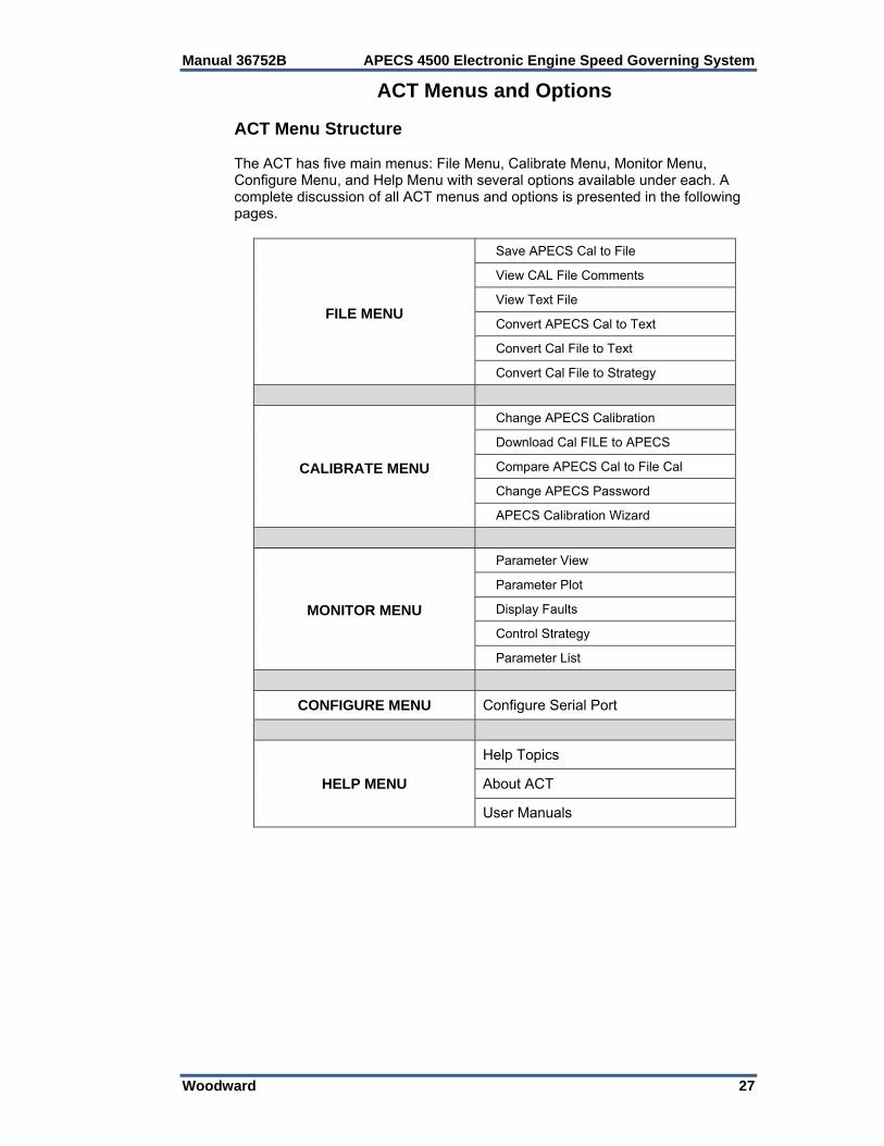
ACT Menus and Options ACT Menu Structure The ACT has five main menus: File Menu, Calibrate Menu, Monitor Menu, Configure Menu, and Help Menu with several options available under each. A complete discussion of all ACT menus and options is presented in the following pages.
FILE MENU
Save APECS Cal to File
View CAL File Comments
View Text File
Convert APECS Cal to Text
Convert Cal File to Text
Convert Cal File to Strategy
CALIBRATE MENU
Change APECS Calibration
Download Cal FILE to APECS
Compare APECS Cal to File Cal
Change APECS Password
APECS Calibration Wizard
MONITOR MENU
Parameter View
Parameter Plot
Display Faults
Control Strategy
Parameter List
CONFIGURE MENU Configure Serial Port
HELP MENU
Help Topics
About ACT
User Manuals
APECS 4500 Electronic Engine Speed Governing System Manual 36752B
28 Woodward
File Menu Purpose The File Menu allows you to perform operations related to viewing, saving and converting files. The following commands are available under the File Menu.
Save APECS Cal to File View Cal File Comments View Text File Convert APECS Cal to Text Convert Cal File to Text Convert Cal File to Strategy
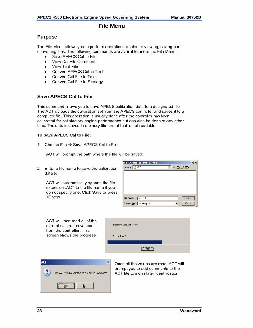
Save APECS Cal to File This command allows you to save APECS calibration data to a designated file. The ACT uploads the calibration set from the APECS controller and saves it to a computer file. This operation is usually done after the controller has been calibrated for satisfactory engine performance but can also be done at any other time. The data is saved in a binary file format that is not readable. To Save APECS Cal to File: 1. Choose File Save APECS Cal to File. ACT will prompt the path where the file will be saved: 2. Enter a file name to save the calibration
data to. ACT will automatically append the file
extension .ACT to the file name if you do not specify one. Click Save or press <Enter>.
ACT will then read all of the
current calibration values from the controller. This screen shows the progress.
Once all the values are read, ACT will prompt you to add comments to the ACT file to aid in later identification.
Manual 36752B APECS 4500 Electronic Engine Speed Governing System
Woodward 29
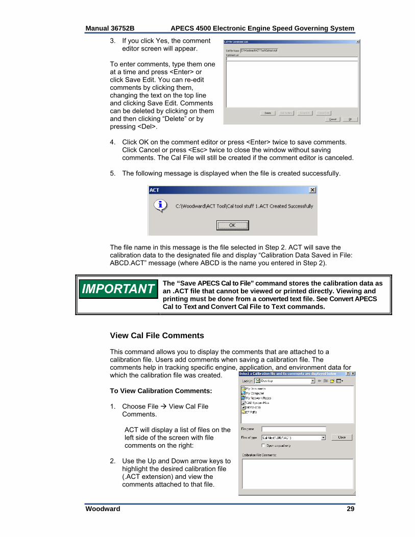
3. If you click Yes, the comment editor screen will appear.
To enter comments, type them one at a time and press <Enter> or click Save Edit. You can re-edit comments by clicking them, changing the text on the top line and clicking Save Edit. Comments can be deleted by clicking on them and then clicking “Delete” or by pressing <Del>. 4. Click OK on the comment editor or press <Enter> twice to save comments.
Click Cancel or press <Esc> twice to close the window without saving comments. The Cal File will still be created if the comment editor is canceled.
5. The following message is displayed when the file is created successfully.
The file name in this message is the file selected in Step 2. ACT will save the calibration data to the designated file and display “Calibration Data Saved in File: ABCD.ACT” message (where ABCD is the name you entered in Step 2).
The “Save APECS Cal to File” command stores the calibration data as an .ACT file that cannot be viewed or printed directly. Viewing and printing must be done from a converted text file. See Convert APECS Cal to Text and Convert Cal File to Text commands.
View Cal File Comments This command allows you to display the comments that are attached to a calibration file. Users add comments when saving a calibration file. The comments help in tracking specific engine, application, and environment data for which the calibration file was created. To View Calibration Comments: 1. Choose File View Cal File
Comments. ACT will display a list of files on the
left side of the screen with file comments on the right:
2. Use the Up and Down arrow keys to
highlight the desired calibration file (.ACT extension) and view the comments attached to that file.

APECS 4500 Electronic Engine Speed Governing System Manual 36752B
30 Woodward
3. Click OK or Cancel to close Comment Viewer. The comments are created or edited when the files are created.
View Text File This command is a convenient way to view text files. 1. Choose File View Text File. 2. ACT will prompt for a text file to view. 3. Select a file and click OK. 4. ACT will open the selected file with the default viewer for that file type. Convert Commands The “Save APECS Cal to File” command, discussed earlier, stores the calibration data as an .ACT file that cannot be viewed or printed directly. Viewing and printing must be done from a converted text file. There are two convert commands available with ACT: “Convert APECS Cal to Text” and “Convert Cal File to Text.” The difference between the two commands is as follows: 1. In “Convert APECS Cal to Text” operation, the calibration set that is
converted is from the APECS unit. 2. In “Convert Cal File to Text” operation, the calibration set that is converted is
from a previously saved file. You may use the View Text File command to view text files. Convert APECS Cal to Text This command allows you to create a text file of APECS calibration data for viewing or printing from any text editor utility in Windows. A printed copy of the calibration data can be useful for future reference. To Convert APECS Calibration to Text: 1. Choose File Convert APECS Cal to Text. 2. ACT will prompt you to enter a name to save the text file. Enter a file and
click OK. ACT will read all of the calibration values from the controller, create and save a text file with the parameter names, values, and units, then display the file using the default text viewer. Convert Cal File to Text This command allows you to convert a previously saved .ACT calibration file to a text file for viewing or printing from any text editor utility in Windows. A printed copy of the calibration data can be useful for future reference.
Manual 36752B APECS 4500 Electronic Engine Speed Governing System
Woodward 31
To Convert Cal File to Text: 1. Choose File Convert Cal File to Text. 2. ACT will prompt you to enter a name to save the text file. Enter a file and
click OK. ACT will read all of the calibration values from the controller, create and save a text file with the parameter names, values, and units, then display the file using the default text viewer. Convert Cal File to Strategy This command is used to convert old ACT files for use with controllers that have a different control strategy version. ACT will: 1. Parse through all of the calibration parameters in the old ACT file. 2. Search for the same calibration parameters in the new ACT file and assign
values from the old calibration. To Convert a Cal File to a New Strategy: 1. Choose File Convert Cal File to Strategy. 2. ACT will prompt you to enter a name to save the text file. Enter a file and
click OK. ACT will read all of the calibration values from the controller create and save a text file with the parameter names, values, and units, then display the file using the default text viewer.
Calibrate Menu The Calibrate Menu allows you to perform operations related to APECS calibration. The following commands are available:
Change APECS Calibration* Download Cal File to APECS* Compare APECS Cal to File Cal Change APECS Password* APECS Calibration Wizard*
(*) These commands can be password protected to prevent unauthorized calibration changes. See “Change APECS Password” for more information. Change APECS Calibration The “Change APECS Calibration” command allows you to calibrate (configure and adjust) various parameters associated with the APECS controller. APECS 4500 is a programmable engine governor. Changing APECS calibration parameters is the means to configure the APECS controller for specific engines, applications and environments, and for adjusting PID gains. The calibration parameters have been organized into categories for your convenience. Browse through the categories to view the specific parameter you want to change or adjust.

APECS 4500 Electronic Engine Speed Governing System Manual 36752B
32 Woodward
Some parameters must be set before the engine can run. Other parameters can be adjusted while the engine is running. A complete list of parameters appears in “Understanding APECS Calibration Parameters” in Chapter 5. All adjustments are stored immediately in non-volatile memory in the APECS unit. The APECS controller will retain the changes even if power is lost or the ACT is disconnected. To Change APECS Calibration Parameters: 1. Choose Calibrate Change APECS Calibration. 2. Set the “View Filter” to select a group of parameters. 3. Use F5/F6 to scroll through the list. 4. To change the highlighted parameter: Enter the new value in the “New Value” field Press <Enter> The new value is written to the controller and then read back, with the result
placed in the “APECS Value” field. 5. Press <Esc> to exit. Download Cal File to APECS The “Download Cal File to APECS” command allows you to download the entire calibration set from a file to the APECS permanent memory. This is a convenient one-step method for:
Reverting back to a known good calibration set after experimenting with new calibration settings
Programming multiple APECS units for a particular application The downloaded file may have been previously configured and calibrated for satisfactory engine performance with another APECS unit. 1. To Download a Cal File to APECS: Choose Calibrate Download Cal
File to APECS. The following screen allows you to select a Cal file to download.
2. Choose a file and click OK. The following screen will show the progress.
Manual 36752B APECS 4500 Electronic Engine Speed Governing System
Woodward 33
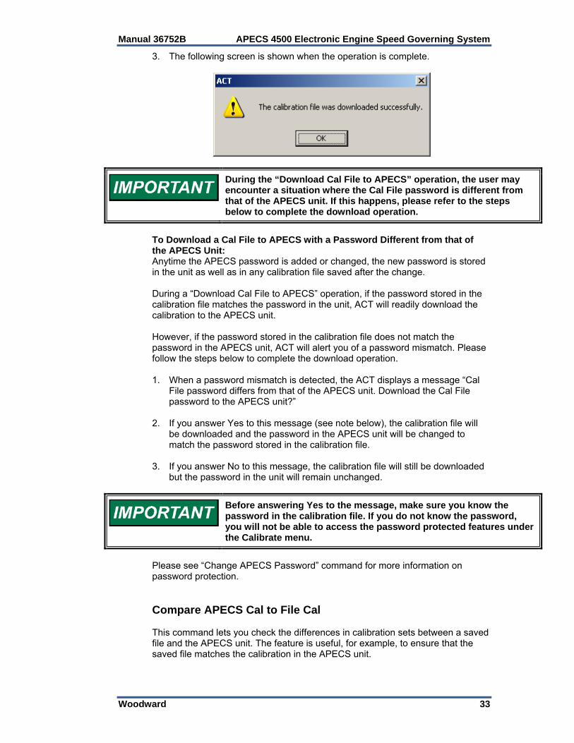
3. The following screen is shown when the operation is complete.
During the “Download Cal File to APECS” operation, the user may encounter a situation where the Cal File password is different from that of the APECS unit. If this happens, please refer to the steps below to complete the download operation.
To Download a Cal File to APECS with a Password Different from that of the APECS Unit: Anytime the APECS password is added or changed, the new password is stored in the unit as well as in any calibration file saved after the change. During a “Download Cal File to APECS” operation, if the password stored in the calibration file matches the password in the unit, ACT will readily download the calibration to the APECS unit. However, if the password stored in the calibration file does not match the password in the APECS unit, ACT will alert you of a password mismatch. Please follow the steps below to complete the download operation. 1. When a password mismatch is detected, the ACT displays a message “Cal
File password differs from that of the APECS unit. Download the Cal File password to the APECS unit?”
2. If you answer Yes to this message (see note below), the calibration file will
be downloaded and the password in the APECS unit will be changed to match the password stored in the calibration file.
3. If you answer No to this message, the calibration file will still be downloaded
but the password in the unit will remain unchanged.
Before answering Yes to the message, make sure you know the password in the calibration file. If you do not know the password, you will not be able to access the password protected features under the Calibrate menu.
Please see “Change APECS Password” command for more information on password protection. Compare APECS Cal to File Cal This command lets you check the differences in calibration sets between a saved file and the APECS unit. The feature is useful, for example, to ensure that the saved file matches the calibration in the APECS unit.

APECS 4500 Electronic Engine Speed Governing System Manual 36752B
34 Woodward
To Compare APECS Cal to File Cal: 1. Choose File Compare APECS Cal to File
Cal. This screen allows you to select a Cal File to compare.
2. Choose a file and Click OK.
This screen will show the progress.
3. Once all parameters have been processed, a
message box will list the compare results. If the parameters in the file match the controller, the following message box appears:
4. Click OK to close. If there were mismatches, the following message will
appear:
You may select "Save to File" if you would like to save a permanent record of the file compare. You will then be asked to select a destination directory and file name.

Manual 36752B APECS 4500 Electronic Engine Speed Governing System
Woodward 35
Change APECS Password This command allows you to add or change a password to protect certain calibration features. The option is useful, for example, to prevent unauthorized changes to a known good calibration set in the APECS unit. By default, the APECS unit is not password protected. To Change APECS Password: 1. Choose Calibrate Change
APECS Password. You will be prompted for the current password.
2. The application will query
the controller to verify that the entered password matches the current password. If the password matches, the “Change” button is enabled:
3. Click “Change” and the application will prompt for the new password:
4. Enter the new password. It should be one word, no spaces, and up to 11
characters long. Once entered, click OK. The application will prompt to reenter the password to make sure that it was typed in properly:
5. Re-enter the password and click
OK. If the two entries of the new password are equal, the new password will be encoded and saved in the controller.
Passwords are upper and lower case sensitive.
APECS 4500 Electronic Engine Speed Governing System Manual 36752B
36 Woodward
After changing your password, please record it in a safe place for future reference. To revert to no password protection, change APECS password to “peg,” which is the default password. ACT Operation with the New Password: Once a password is added or changed, the following calibration features become password protected:
Change APECS Calibration Download Cal File to APECS Change APECS Password APECS Calibration Wizard
At the start of any future sessions, ACT will always prompt you to enter the new password to gain access to these features. You only need to enter the password once during any session to gain access to all the password protected features. APECS Calibration Wizard The APECS Calibration Wizard is an interactive guide to help you get your controller unit up and running as quickly as possible. To Calibrate a Controller Unit Using the APECS Calibration Wizard: 1. Choose Calibrate Calibration Wizard. 2. The Wizard will give you the option to use the default calibration or modify
the existing one. If you select the default calibration, the Wizard will reset all calibration parameters.
3. Press <Enter> to continue or <Esc> to abort the Wizard. If you press <Enter> the Wizard will lead you through the calibration process
with a series of questions. When all questions have been answered the Wizard will ask you to confirm that the values entered are accurate.
4. Press <Enter> to confirm the values, <PgUp> to go back and change the
values, or <Esc> to abort the Wizard. If you press <Enter>, the APECS Wizard will download the new calibration
and reset all APECS parameters. This will complete the APECS Wizard operation.
The APECS Calibration Wizard only covers basic calibration. It does not automatically assure optimum engine operation. Please refer to APECS Calibration Procedures for more information.
5. You are now ready to run your engine. Press any key to go directly to the
Parameter Plot screen where you can adjust the PID gains.

Manual 36752B APECS 4500 Electronic Engine Speed Governing System
Woodward 37
Monitor Menu The Monitor Menu allows you to observe engine and APECS operation in real time. The following commands are available under the Monitor Menu.
Parameter View Parameter Plot Display Faults Control Strategy Parameter List
Parameter View This command allows you to view certain operating variables (i.e., engine speed) in real time. To View Parameter Values in Real Time: 1. Choose Monitor Parameter View.
The application will launch the view screen.
2. The screen automatically starts
reading values from the controller and displaying the values.
3. To stop the updating, click on Stop.
The button name will then change to ‘Start.’ Clicking it again will start updating again.
If any other screen is opened that requires communication with the controller while the screen is updating, the Parameter View screen will be automatically stopped.
Parameter Plot The Parameter Plot command lets you view engine performance on screen in the form of a real-time graph. This feature allows you to perturb the system and observe the response to fine tune engine performance. To View Parameter Plot in Real Time: Select Monitor Parameter Plot. The application will launch and start the parameter plot view.
APECS 4500 Electronic Engine Speed Governing System Manual 36752B
38 Woodward
The application will read the previously saved configuration and request the controller to start sending the parameter values. The controller sends the data to the PC at a rate that varies with the number of parameters being monitored. The application uses the Windows timer functionality to update the screen at the specified rate. Note that if the PC is very busy, the timer accuracy will vary, therefore, the screen and generated data files should be considered as reference only. The X-axis time scale (25 seconds in the example screen) may be shorter than configured due to the resolution of the monitor. This value will be adjusted when the graph is resized. This also applies to the print functionality for this screen. All of the data will be recorded in a revolving buffer for use by the “Save to File” feature (see below). The axis scales, parameter names, update resolution and time scale on the Parameter Plot may be changed as described in the Plot Setup screen. PID Gain Adjustments from Plot Display Screen After initial calibration, most engines require only a minor adjustment to PID gains to fine tune the system to its optimum level. ACT provides a convenient means of adjusting the PID gains directly from the Plot Display screen. To Make PID Gain Adjustments from Plot Display Screen: 1. Press the letter <P> for proportional, <I> for integral, or <D> for derivative
gain adjustment. The application will enable the gain you selected. 2. Use the Up or Down arrow keys to increase or decrease the present value.
The arrow keys adjust the values by 0.004. New values may be typed in directly. Hit <Enter> after you type in a value. The application will save the new value in the APECS unit.
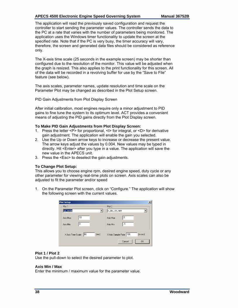
3. Press the <Esc> to deselect the gain adjustments. To Change Plot Setup: This allows you to choose engine rpm, desired engine speed, duty cycle or any other parameter for viewing real-time plots on screen. Axis scales can also be adjusted to fit the parameter and/or speed 1. On the Parameter Plot screen, click on “Configure.” The application will show
the following screen with the current values.
Plot 1 / Plot 2 Use the pull-down to select the desired parameter to plot. Axis Min / Max Enter the minimum / maximum value for the parameter value.
Manual 36752B APECS 4500 Electronic Engine Speed Governing System
Woodward 39
X Axis Time Scale Controls how much data is displayed on the X axis. This value may automatically adjust for screen resolution. X Axis Sample Rate Controls how often the data from the controller is used to update the screen. Data received between timer ticks is discarded. 2. Clicking OK will save this information in the Windows Registry so that it will
be remembered the next time the program is started.
The Calibration Wizard will automatically set up the plots if there are no saved defaults.
Display Faults This command allows you to display present faults in real-time. This means if new faults occur while you are monitoring, the screen will automatically update to display the current faults. The display will also show historical fault codes that have been previously logged but do not currently exist. Historical fault codes are helpful when tracking down intermittent faults. To Display Faults in Real Time: 1. Choose Monitor Display Faults
from the main menu. The application will launch the Fault view.
The application will update the
display every time the controller sends the fault_flags status. This happens several times a second.
2. Click on the “Pause” button to stop the automatic update of this screen. The
text on the button will change to “Start” and clicking it again will re-start the automatic updating.
If any other screen requests data from the controller while this screen is updating, this screen will automatically Pause.
Control Strategy This command allows you to check the version of the control strategy in use. This information may be needed for strategy identification purposes and for future updates. Parameter List The Parameter List screen allows the user to adjust which parameters are displayed on the Parameter View display.
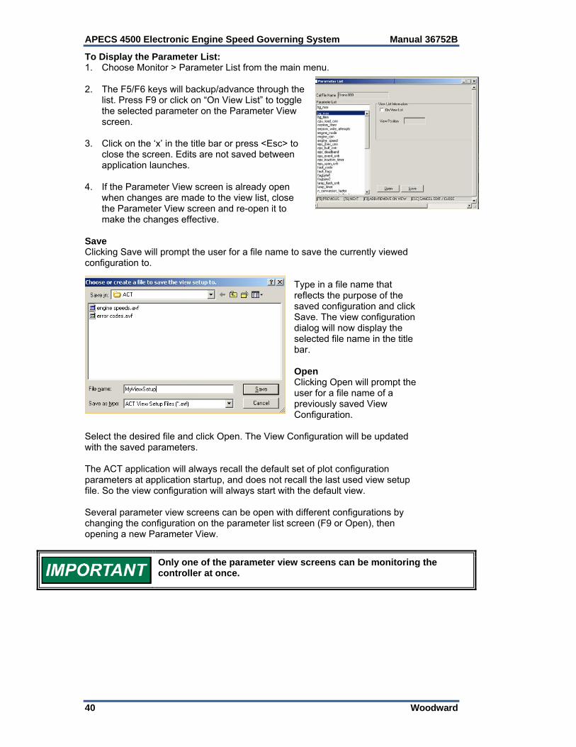
APECS 4500 Electronic Engine Speed Governing System Manual 36752B
40 Woodward
To Display the Parameter List: 1. Choose Monitor > Parameter List from the main menu. 2. The F5/F6 keys will backup/advance through the
list. Press F9 or click on “On View List” to toggle the selected parameter on the Parameter View screen.
3. Click on the ‘x’ in the title bar or press <Esc> to
close the screen. Edits are not saved between application launches.
4. If the Parameter View screen is already open
when changes are made to the view list, close the Parameter View screen and re-open it to make the changes effective.
Save Clicking Save will prompt the user for a file name to save the currently viewed configuration to.
Type in a file name that reflects the purpose of the saved configuration and click Save. The view configuration dialog will now display the selected file name in the title bar. Open Clicking Open will prompt the user for a file name of a previously saved View Configuration.
Select the desired file and click Open. The View Configuration will be updated with the saved parameters. The ACT application will always recall the default set of plot configuration parameters at application startup, and does not recall the last used view setup file. So the view configuration will always start with the default view. Several parameter view screens can be open with different configurations by changing the configuration on the parameter list screen (F9 or Open), then opening a new Parameter View.
Only one of the parameter view screens can be monitoring the controller at once.
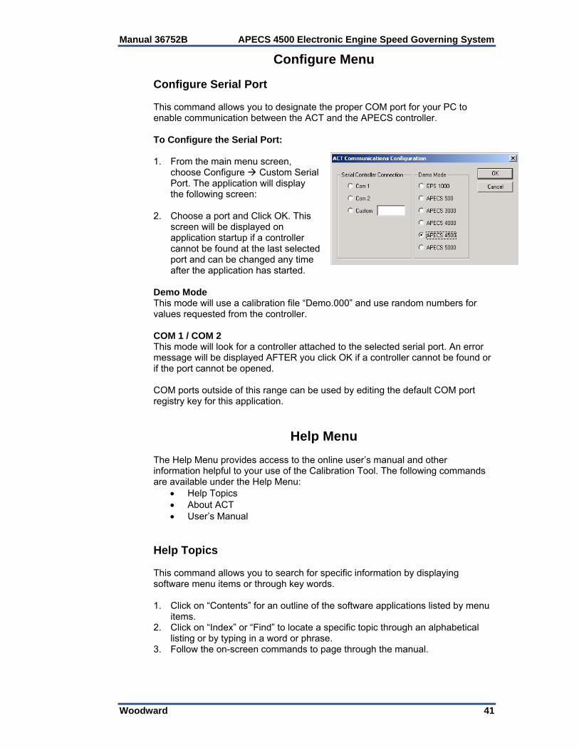
Manual 36752B APECS 4500 Electronic Engine Speed Governing System
Woodward 41
Configure Menu Configure Serial Port This command allows you to designate the proper COM port for your PC to enable communication between the ACT and the APECS controller. To Configure the Serial Port: 1. From the main menu screen,
choose Configure Custom Serial Port. The application will display the following screen:
2. Choose a port and Click OK. This
screen will be displayed on application startup if a controller cannot be found at the last selected port and can be changed any time after the application has started.
Demo Mode This mode will use a calibration file “Demo.000” and use random numbers for values requested from the controller. COM 1 / COM 2 This mode will look for a controller attached to the selected serial port. An error message will be displayed AFTER you click OK if a controller cannot be found or if the port cannot be opened. COM ports outside of this range can be used by editing the default COM port registry key for this application.
Help Menu The Help Menu provides access to the online user’s manual and other information helpful to your use of the Calibration Tool. The following commands are available under the Help Menu:
Help Topics About ACT User’s Manual
Help Topics This command allows you to search for specific information by displaying software menu items or through key words. 1. Click on “Contents” for an outline of the software applications listed by menu
items. 2. Click on “Index” or “Find” to locate a specific topic through an alphabetical
listing or by typing in a word or phrase. 3. Follow the on-screen commands to page through the manual.

APECS 4500 Electronic Engine Speed Governing System Manual 36752B
42 Woodward
About ACT This command displays the version of the calibration tool that you are currently using. This information is important for tool identification purposes and for servicing support. User’s Manual This command accesses the User’s Manual, which includes comprehensive information on the APECS 4500 controller, wiring diagrams, ACT software menus, and calibration parameters. The manual may be viewed online or printed for future reference.

Manual 36752B APECS 4500 Electronic Engine Speed Governing System
Woodward 43
Chapter 4. CAN Operation
CAN Communications To use CAN (Controller Area Network), the APECS 4500 version that supports CAN must be purchased. The APECS 4500 can provide either J1939 or customer specific protocol, depending on the version purchased.
CAN Connections CANL (J1-6) and CANH (J1-7) lines are used for CAN communications. As a general rule for CAN networks, use the following and refer to the table below.
Wiring length restrictions depend on the baud rate used and the APECS 4500 only supports 250 kbps.
The “Trunk” is the length between the two units at the physical ends of the network; or the two termination points if the end units have a drop cable.
The “Cumulative Drop” is the added length of all drop wires from the trunk to the devices.
The “Maximum Drop” is the maximum allowed for any 1 drop. The limits below are the maximum allowed by the CAN standard, when isolated. Shorter lengths in practice are highly recommended in order to maintain a high level of reliability.
Since APECS 4500 CAN communications is not isolated, a distance of 40 meters should not be exceeded without adding an isolator.
BAUD RATE TRUNK LENGTH CUMULATIVE
DROP MAXIMUM
DROP
250 kbps 250 m (820 ft) 78 m (256 ft) 6 m (20 ft)
CAN Network Termination CAN networks must be terminated with a 121 Ω ±1% differential resistance at each end of the network. It is necessary to terminate the network to prevent interference caused by signal reflections. Depending on length, may CAN networks will not operate at all without the proper termination. Generally it is recommended not to build the termination into a node since CAN is intended to be a plug-n-play type network with RIUP (remove and insert under power). However, no specific restrictions are placed on the inclusion of termination resistors in a node. Termination resistors must be installed only at the physical ends of the network. Terminating other midpoint units can overload the network and stop all communications. As a rule, no matter how many units are on a network, there should never be more than two terminations installed. Termination is a simple 121 Ω, ¼ watt, 1% metal film resistor placed between CAN high and CAN low terminals (differential termination) on or near the two end units.
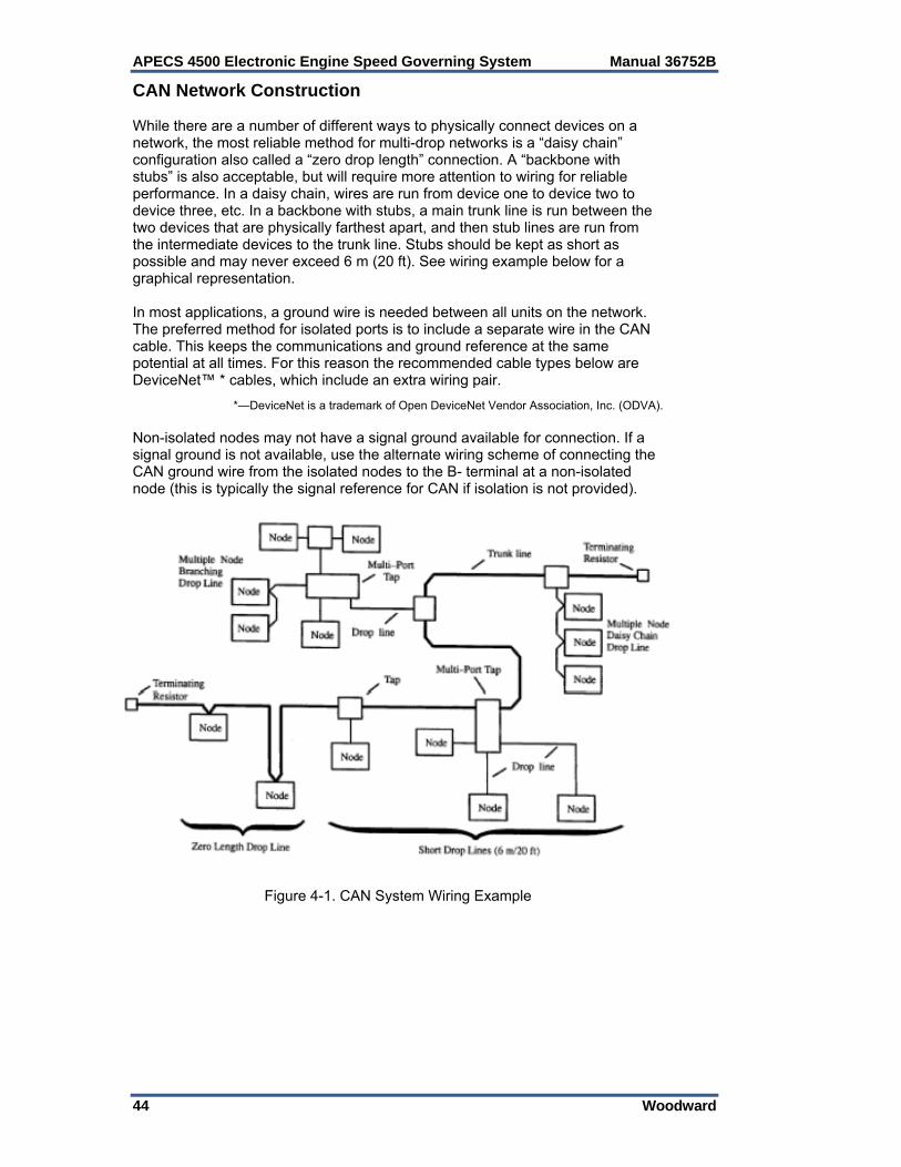
APECS 4500 Electronic Engine Speed Governing System Manual 36752B
44 Woodward
CAN Network Construction While there are a number of different ways to physically connect devices on a network, the most reliable method for multi-drop networks is a “daisy chain” configuration also called a “zero drop length” connection. A “backbone with stubs” is also acceptable, but will require more attention to wiring for reliable performance. In a daisy chain, wires are run from device one to device two to device three, etc. In a backbone with stubs, a main trunk line is run between the two devices that are physically farthest apart, and then stub lines are run from the intermediate devices to the trunk line. Stubs should be kept as short as possible and may never exceed 6 m (20 ft). See wiring example below for a graphical representation. In most applications, a ground wire is needed between all units on the network. The preferred method for isolated ports is to include a separate wire in the CAN cable. This keeps the communications and ground reference at the same potential at all times. For this reason the recommended cable types below are DeviceNet™ * cables, which include an extra wiring pair.
*—DeviceNet is a trademark of Open DeviceNet Vendor Association, Inc. (ODVA). Non-isolated nodes may not have a signal ground available for connection. If a signal ground is not available, use the alternate wiring scheme of connecting the CAN ground wire from the isolated nodes to the B- terminal at a non-isolated node (this is typically the signal reference for CAN if isolation is not provided).
Figure 4-1. CAN System Wiring Example
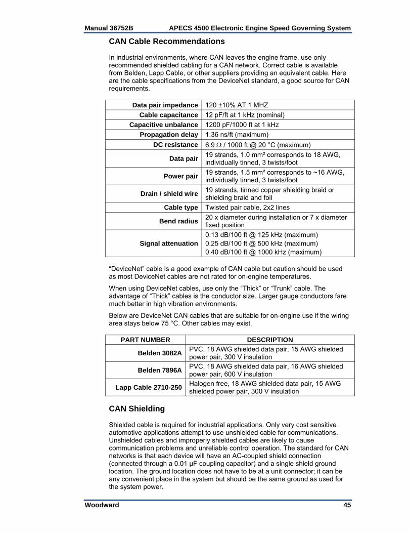
Manual 36752B APECS 4500 Electronic Engine Speed Governing System
Woodward 45
CAN Cable Recommendations In industrial environments, where CAN leaves the engine frame, use only recommended shielded cabling for a CAN network. Correct cable is available from Belden, Lapp Cable, or other suppliers providing an equivalent cable. Here are the cable specifications from the DeviceNet standard, a good source for CAN requirements.
Data pair impedance 120 ±10% AT 1 MHZ
Cable capacitance 12 pF/ft at 1 kHz (nominal)
Capacitive unbalance 1200 pF/1000 ft at 1 kHz
Propagation delay 1.36 ns/ft (maximum)
DC resistance 6.9 / 1000 ft @ 20 °C (maximum)
Data pair19 strands, 1.0 mm² corresponds to 18 AWG, individually tinned, 3 twists/foot
Power pair19 strands, 1.5 mm² corresponds to ~16 AWG, individually tinned, 3 twists/foot
Drain / shield wire19 strands, tinned copper shielding braid or shielding braid and foil
Cable type Twisted pair cable, 2x2 lines
Bend radius20 x diameter during installation or 7 x diameter fixed position
Signal attenuation0.13 dB/100 ft @ 125 kHz (maximum) 0.25 dB/100 ft @ 500 kHz (maximum) 0.40 dB/100 ft @ 1000 kHz (maximum)
“DeviceNet” cable is a good example of CAN cable but caution should be used as most DeviceNet cables are not rated for on-engine temperatures. When using DeviceNet cables, use only the “Thick” or “Trunk” cable. The advantage of “Thick” cables is the conductor size. Larger gauge conductors fare much better in high vibration environments. Below are DeviceNet CAN cables that are suitable for on-engine use if the wiring area stays below 75 °C. Other cables may exist.
PART NUMBER DESCRIPTION
Belden 3082APVC, 18 AWG shielded data pair, 15 AWG shielded power pair, 300 V insulation
Belden 7896APVC, 18 AWG shielded data pair, 16 AWG shielded power pair, 600 V insulation
Lapp Cable 2710-250Halogen free, 18 AWG shielded data pair, 15 AWG shielded power pair, 300 V insulation
CAN Shielding Shielded cable is required for industrial applications. Only very cost sensitive automotive applications attempt to use unshielded cable for communications. Unshielded cables and improperly shielded cables are likely to cause communication problems and unreliable control operation. The standard for CAN networks is that each device will have an AC-coupled shield connection (connected through a 0.01 μF coupling capacitor) and a single shield ground location. The ground location does not have to be at a unit connector; it can be any convenient place in the system but should be the same ground as used for the system power.

APECS 4500 Electronic Engine Speed Governing System Manual 36752B
46 Woodward
Figure 4-2. CAN Shielding
CAN Basics Data messages transmitted from any node on a CAN bus do not contain addresses of either the transmitting node, or of any intended receiving node. Instead, the content of the message is labeled by an identifier that is unique throughout the network. All other nodes on the network receive the message and each performs an acceptance test on the identifier to determine if the message, and thus its content, is relevant to that particular node. If the message is relevant, it will be processed; otherwise it is ignored. The unique identifier also determines the priority of the message. The lower the numerical value of the identifier, the higher the priority. In situations where two or more nodes attempt to transmit at the same time, a non-destructive arbitration technique guarantees that messages are sent in order of priority and that no messages are lost.
Manual 36752B APECS 4500 Electronic Engine Speed Governing System
Woodward 47
Error Handling The error handling of CAN is one of the really strong advantages of the protocol. The error detection mechanisms are extensive and the fault confinement algorithms are well developed. The error handling and retransmission of the messages is done automatically by the CAN hardware. The error handling aims at detecting errors in messages appearing on the CAN bus, so that the transmitter can retransmit an erroneous message. Every CAN controller along a bus will try to detect errors within a message. If an error is found, the discovering node will transmit an Error Flag, thus destroying the bus traffic. The other nodes will detect the error caused by the Error Flag (if they haven't already detected the original error) and take appropriate action, i.e. discard the current message.
Fine Fault Confinement A faulty node within a system can ruin the transmission of a whole system, by occupying all the available bandwidth. The CAN protocol has a built-in feature that prevents a faulty node from blocking the system. A faulty node is eventually excluded from further sending on the CAN bus.
Bit-wise Arbitration The priority of a CAN message is determined by the numerical value of its identifier. The numerical value of each message identifier (and thus the priority of the message) is assigned during the initial phase of system design. The identifier with the lowest numerical value has the highest priority. Any potential bus conflicts are resolved by bit wise arbitration in accordance with the wired-and mechanism, by which a dominant state (logic 0) overwrites a recessive state (logic 1).
APECS 4500 CAN Specific Parameter Format The APECS 4500 uses a Little-Endian format when handling multiple-byte parameters (i.e. a position demand of 50% is $FF0F, not $0FFF). All parameters shall use this format unless otherwise specified. CAN Bit Timing The APECS 4500 bit timing is limited to provide a data rate of 250 kbps only. CAN Fault Indication When the EXTERNAL_ANALOG_MODE is configured to receive demanded speed from CAN, if new demanded speed updates are not received within the configured CAN_LOST_DELAY a CAN_DEFAULT_SPEED is taken. There is no fault indication.
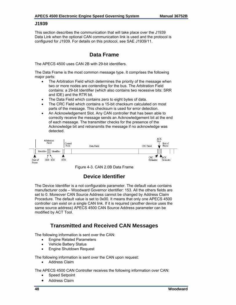
APECS 4500 Electronic Engine Speed Governing System Manual 36752B
48 Woodward
J1939 This section describes the communication that will take place over the J1939 Data Link when the optional CAN communication link is used and the protocol is configured for J1939. For details on this protocol, see SAE J1939/11.
Data Frame The APECS 4500 uses CAN 2B with 29-bit identifiers. The Data Frame is the most common message type. It comprises the following major parts:
The Arbitration Field which determines the priority of the message when two or more nodes are contending for the bus. The Arbitration Field contains: a 29-bit Identifier (which also contains two recessive bits: SRR and IDE) and the RTR bit.
The Data Field which contains zero to eight bytes of data. The CRC Field which contains a 15-bit checksum calculated on most
parts of the message. This checksum is used for error detection. An Acknowledgement Slot. Any CAN controller that has been able to
correctly receive the message sends an Acknowledgement bit at the end of each message. The transmitter checks for the presence of the Acknowledge bit and retransmits the message if no acknowledge was detected.
Figure 4-3. CAN 2.0B Data Frame
Device Identifier The Device Identifier is a not configurable parameter. The default value contains manufacturer code – Woodward Governor identifier: 153. All the others fields are set to 0. Moreover CAN Source Address cannot be changed by Address Claim Procedure. The default value is set to 0x00. It means that only one APECS 4500 controller can exist on a single CAN link. If it is required (another device uses the same source address) APECS 4500 CAN Source Address parameter can be modified by ACT Tool.
Transmitted and Received CAN Messages The following information is sent over the CAN:
Engine Related Parameters Vehicle Battery Status Engine Shutdown Request
The following information is sent over the CAN upon request:
Address Claim The APECS 4500 CAN Controller receives the following information over CAN:
Speed Setpoint
Address Claim
Manual 36752B APECS 4500 Electronic Engine Speed Governing System
Woodward 49
Supported Frames
PGN 61444 Electronic Engine Controller 1 - EEC1 Engine related parameters: Transmission Repetition Rate: 20 ms Data Length: 8 Default Priority: 3 Parameter Group Number: 61444 (0xF004) Start Position Length Parameter Name SPN 4-5 2 bytes Engine Speed 190 7.1 4 bits Engine Starter Mode 1675
PGN 61443 Electronic Engine Controller 2 - EEC2 Identifies electronic engine control related parameters. Transmission Repetition Rate: 50 ms Data Length: 8 Default Priority: 3 Parameter Group Number: 61443 (0xF003) Start Position Length Parameter Name SPN 1.1 2 bits Accelerator Pedal 1 Low Idle Switch 558 2 1 byte Accelerator Pedal Position 1 91
PGN 65271 Vehicle Electrical Power 1 - VEP1 Transmission Repetition Rate: 1 s Data Length: 8 Default Priority: 6 Parameter Group Number: 65271 (0xFEF7) Start Position Length Parameter Name SPN 7-8 2 bytes Keyswitch Battery Potential 158
PGN 65252 Shutdown – SHUTDN Transmission Repetition Rate: 1 s Data Length: 8 Default Priority: 6 Parameter Group Number: 65252 (0xFEE4) Start Position Length Parameter Name SPN 4.1 2 bits Engine Wait to Start Lamp 1081
PGN 0 (R) Torque/Speed Control 1 - TSC1 Data Length: 8 Default Priority: 3 Parameter Group Number: 0 (0x0) Start Position Length Parameter Name SPN 2-3 2 bytes Engine Requested Speed/Speed Limit 898 This frame is preceded by the unit only when EXTERNAL_ANALOG_INPUT is set to 40 (CAN Input). Otherwise this frame is ignored by the unit.
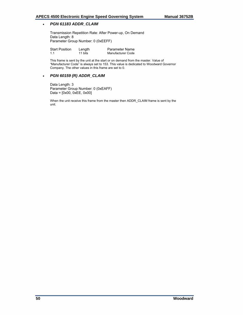
APECS 4500 Electronic Engine Speed Governing System Manual 36752B
50 Woodward
PGN 61183 ADDR_CLAIM Transmission Repetition Rate: After Power-up, On Demand Data Length: 8 Parameter Group Number: 0 (0xEEFF) Start Position Length Parameter Name 1.1 11 bits Manufacturer Code This frame is sent by the unit at the start or on demand from the master. Value of “Manufacturer Code” is always set to 153. This value is dedicated to Woodward Governor Company. The other values in this frame are set to 0.
PGN 60159 (R) ADDR_CLAIM Data Length: 3 Parameter Group Number: 0 (0xEAFF) Data = [0x00, 0xEE, 0x00] When the unit receive this frame from the master then ADDR_CLAIM frame is sent by the unit.
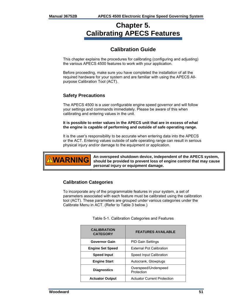
Manual 36752B APECS 4500 Electronic Engine Speed Governing System
Woodward 51
Chapter 5. Calibrating APECS Features
Calibration Guide This chapter explains the procedures for calibrating (configuring and adjusting) the various APECS 4500 features to work with your application. Before proceeding, make sure you have completed the installation of all the required hardware for your system and are familiar with using the APECS All-purpose Calibration Tool (ACT). Safety Precautions The APECS 4500 is a user configurable engine speed governor and will follow your settings and commands immediately. Please be aware of this when calibrating and entering values in the unit. It is possible to enter values in the APECS unit that are in excess of what the engine is capable of performing and outside of safe operating range. It is the user’s responsibility to be accurate when entering data into the APECS or the ACT. Entering values outside of safe operating range can result in serious physical injury and/or damage to the equipment or application.
An overspeed shutdown device, independent of the APECS system, should be provided to prevent loss of engine control that may cause personal injury or equipment damage.
Calibration Categories To incorporate any of the programmable features in your system, a set of parameters associated with each feature must be calibrated using the calibration tool (ACT). These parameters are grouped under various categories under the Calibrate Menu in ACT. (Refer to Table 3 below.)
Table 5-1. Calibration Categories and Features
CALIBRATION CATEGORY
FEATURES AVAILABLE
Governor Gain PID Gain Settings
Engine Set Speed External Pot Calibration
Speed Input Speed Input Calibration
Engine Start Autocrank, Glowplugs
Diagnostics Overspeed/Underspeed Protection
Actuator Output Actuator Current Protection
APECS 4500 Electronic Engine Speed Governing System Manual 36752B
52 Woodward
For basic APECS operation to begin, you only need to configure two parameters: PULSES_PER_REV and PULSES_PER_UPDATE (see Speed Input Configuration). All other parameters are preset to values that will work with many applications.
Calibrating an APECS Unit Once the system set-up is complete it is fairly easy to calibrate an APECS 4500 controller. Before proceeding with calibration, please ensure that the controller unit is connected to the COM port and powered. Follow the steps below for calibrating your APECS controller unit. 1. If an icon for the Calibration Tool exists, double click on it to start the ACT
software. 2. If no icon exists, click on the Start button, highlight “Programs,” find the ACT
software and click to start it. 3. Make sure the COM port designation in ACT matches the serial port on the
back of your PC. Follow the procedure outlined in the Configure Menu to change the COM
port assignment, if needed. 4. If you do not use the Wizard, calibrate the speed input for the type of speed
sensor, SPEED_TYPE as well as the appropriate values for PULSES_PER_REV and PULSES_PER_UPDATE. Refer to “Speed Input Configuration Parameters”.
5. If you wish to use the Wizard for basic calibration, refer to “APECS
Calibration Wizard.” The Wizard is an interactive guide to help you get your controller running as quickly as possible.
6. Beyond basic calibration, there are many parameters associated with
APECS that can help enhance the performance of your engine. Read the section on “Understanding APECS Calibration Parameters” and decide on the parameters you would like to adjust.
7. Access “Change APECS Calibration” option from the Calibrate menu and
select the desired parameter from the appropriate category. Adjust the value of the parameter as needed.
8. Repeat Step 5 until all desired parameters have been adjusted and
satisfactory engine performance has been achieved. 9. You do not need to save the new calibration settings. All settings are
automatically saved in the controller and remain in memory after shutdown.

Manual 36752B APECS 4500 Electronic Engine Speed Governing System
Woodward 53
Saving a Calibration Set to File After satisfactory engine performance is achieved, it is recommended that you save the calibration set to a file. A saved file allows you to experiment with other calibration settings and still
be able to recall the saved calibration set. A saved calibration set can be used for configuring additional APECS units. To Save a Calibration Set to File: 1. Access the File Menu to activate the “Save APECS Cal to File” command. 2. Enter a file name to save the calibration data to a designated file. 3. When prompted to edit the comment list, enter information that will help you
keep track of specific engine, application and environment data associated with the file.
4. ACT will save the calibration set and automatically append the file extension
“.ACT” to the file name. Calibrating an APECS Unit with a Saved Calibration File You may wish to calibrate additional APECS units with a saved calibration file for consistent, optimized operation. To Calibrate an APECS Unit with a Saved Calibration File: 1. Access the Calibrate menu to activate the “Download Cal File to APECS”
command. 2. Select the appropriate file to download (refer to the comment list on the right
side of the screen to help identify the desired file). Enter password if prompted.
3. ACT will download file calibration to APECS permanent memory. 4. Repeat Steps 1 and 2 if multiple APECS units are to be calibrated.
The APECS unit must be powered up, but need not be mounted on the engine to carry out the calibration procedure.
Understanding APECS Calibration Parameters This section provides answers to frequently asked questions about calibration parameters, lists parameters, and provides calibration procedures.

APECS 4500 Electronic Engine Speed Governing System Manual 36752B
54 Woodward
Frequently Asked Questions What is a calibration parameter? A parameter is a numerical value that helps the calibrator adjust or set the APECS controller. Once fixed by a calibrator, the parameter is not subject to change while the system is operating. APECS calibration parameters are used not only to adjust and set the controller but also to configure it properly for different applications. Why do we need to calibrate the APECS system? APECS 4500 is a software programmable system and has no manual adjustment. Calibrating is the only means of configuring and adjusting the controller for your specific application. Do I need to calibrate ALL the parameters to make my system work? No. Two parameters, PULSES_PER_UPDATE and PULSES_PER_REV, are factory set to prevent the APECS unit from calculating an engine speed and driving the actuators. These two parameters must be calibrated to a non-zero value before normal APECS operation can begin. Other parameters are preset to values that will work with many engines and applications. However, it is recommended that you review all settings for your own application. Is it possible to enter values in APECS in excess of what the application is capable of performing? Yes. While ACT (the calibration tool) restricts you from entering values outside of the specified range, the range itself is fairly wide and it is possible to enter values in excess of what your application is capable of performing. For example, it is possible to command engine speeds up to 8192 rpm with ACT. Your engine may or may not be able to operate at this speed. It is also possible to damage the generator or pump attached to your engine by commanding maximum engine speed because while the engine may be capable of performing at the rated rpm, the generator or pump is likely to have a lower rpm rating than the engine. Furthermore, there are certain parameters that are used to properly configure an application. Entering incorrect values for these parameters will result in improper configuration and may make the engine run at maximum throttle. Entering values outside of safe operating range can result in serious physical injury and/or damage to the equipment.

Manual 36752B APECS 4500 Electronic Engine Speed Governing System
Woodward 55
List of Parameters
CATEGORY PARAMETER DESCRIPTION FACTORY
CAL
Governor Gain
Calibration
DERIVATIVE_GAIN Speed stability 1
INTEGRAL_GAIN Steady state speed 2
PROPORTIONAL_GAIN Transient response 5
MASTER_GAIN Combined PID gain response
1
Engine Set Speed
Calibration
BRAKE_DELAY Delay for return to idle, mode 023
15
EXTERNAL_ANALOG_MODE External analog input configuration
0
RAMP_DOWN_RATE Engine speed ramp down rate
1000
RAMP_UP_RATE Engine speed ramp up rate
1000
SET_SPEED_1 Engine set speed 1 1800
SET_SPEED_2 Engine set speed 2 1900
SET_SPEED_3 Engine set speed 3 2000
SET_SPEED_4 Engine set speed 4 2500
SET_SPEED_MAX Maximum increment speed
2600
SET_SPEED_MIN Minimum decrement speed
1000
SET_SPEED_TRIM Engine trim speed (rpm)
200
SET_SPEED_WARMUP Engine warm up speed
1800
SPEED_DECREASE_DELAY Multi-speed decrease delay time (sec)
0
SWITCH_CONFIGURATION 1,2,3,4: multispeed, 5: variable speed
1
WARM_UP_TIME Time spent at warm up speed
0
Speed Input
Configuration
SPEED_TYPE
Mag Pickup = 128
Coil Ignition = 2
Magneto = 3
Hall Effect = 131
128
PULSES_PER_REV No. of pulses per engine revolution
0
PULSES_PER_UPDATE No. of pulses until next engine speed update
0
Engine Start Calibration
AUTOCRANK_CRANK_TIME
Time autocrank holds crank solenoid on (sec)
5
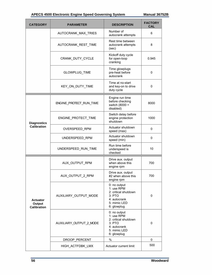
APECS 4500 Electronic Engine Speed Governing System Manual 36752B
56 Woodward
CATEGORY PARAMETER DESCRIPTION FACTORY
CAL
AUTOCRANK_MAX_TRIES Number of autocrank attempts
6
AUTOCRANK_REST_TIME Rest time between autocrank attempts (sec)
8
CRANK_DUTY_CYCLE Kickoff duty cycle for open-loop cranking
0.945
GLOWPLUG_TIME Time glowplugs pre-heat before autocrank
0
KEY_ON_DUTY_TIME Time at no-start and key-on to drive duty cycle
0
Diagnostics Calibration
ENGINE_PROTECT_RUN_TIME
Engine run time before checking switch (8000 = disabled)
8000
ENGINE_PROTECT_TIME Switch delay before engine protection shutdown
1000
OVERSPEED_RPM Actuator shutdown speed (max)
0
UNDERSPEED_RPM Actuator shutdown speed (min)
0
UNDERSPEED_RUN_TIME Run time before underspeed is checked
10
Actuator Output
Calibration
AUX_OUTPUT_RPM Drive aux. output when above this engine rpm
700
AUX_OUTPUT_2_RPM Drive aux. output #2 when above this engine rpm
700
AUXILIARY_OUTPUT_MODE
0: no output 1: use RPM 2: critical shutdown 3: PTO 4: autocrank 5: mimic LED 6: glowplug
0
AUXILIARY_OUTPUT_2_MODE
0: no output 1: use RPM 2: critical shutdown 3: PTO 4: autocrank 5: mimic LED 6: glowplug
0
DROOP_PERCENT % 0
HIGH_ACTFDBK_LMX Actuator current limit 500
Manual 36752B APECS 4500 Electronic Engine Speed Governing System
Woodward 57
Calibration Procedures: PID Gains Adjustment These parameters allow proportional, integral and derivative gains to be programmed by the user. Calibration Parameters Needing Configuration: DERIVATIVE_GAIN Engine speed governor derivative gain (unitless). Derivative gain is used to improve stability. Increase derivative gain until response has a slight overshoot on load transients. INTEGRAL_GAIN Engine speed governor integral gain (unitless). Integral gain is used to remove steady-state errors. Increase integral gain until speed begins to oscillate, and then decrease until oscillation stops. If oscillations do not occur, bump actuator lever, then decrease integral gain until oscillation stops. PROPORTIONAL_GAIN Engine speed governor proportional gain (unitless). Proportional gain is used to improve response time. A maximum amount of proportional gain should be used while still maintaining stability. Increase proportional gain until speed begins to oscillate, then decrease until oscillation stops. If oscillations do not occur, bump actuator lever, then decrease proportional gain until oscillation stops. MASTER_GAIN As a multiplier to the PID gains, master gain is used to increase or decrease the combined derivative, integral, and proportional response with a single gain. For example, the effective proportional gain used is PROPORTIONAL_GAIN X MASTER_GAIN. This permits adjusting all three gains with a single calibration parameter. Range: 0-255. Default value: 1.0. PID Gain Settings Response Plots ACT allows the user to adjust the P, I, and D gain settings and observe the response directly on screen in the form of a real-time plot. The plots on the following page illustrate the various conditions a user may encounter while tuning an application. Although conditions may vary according to application and nature of load, these plots are typical of what is often observed. Figures 5-1 through 5-5 illustrate less desirable conditions often encountered while tuning an application and suggest probable causes. Figure 5-6 shows a plot of a properly tuned application. Although conditions may vary according to application and nature of load, this plot is typical of what is often desired.
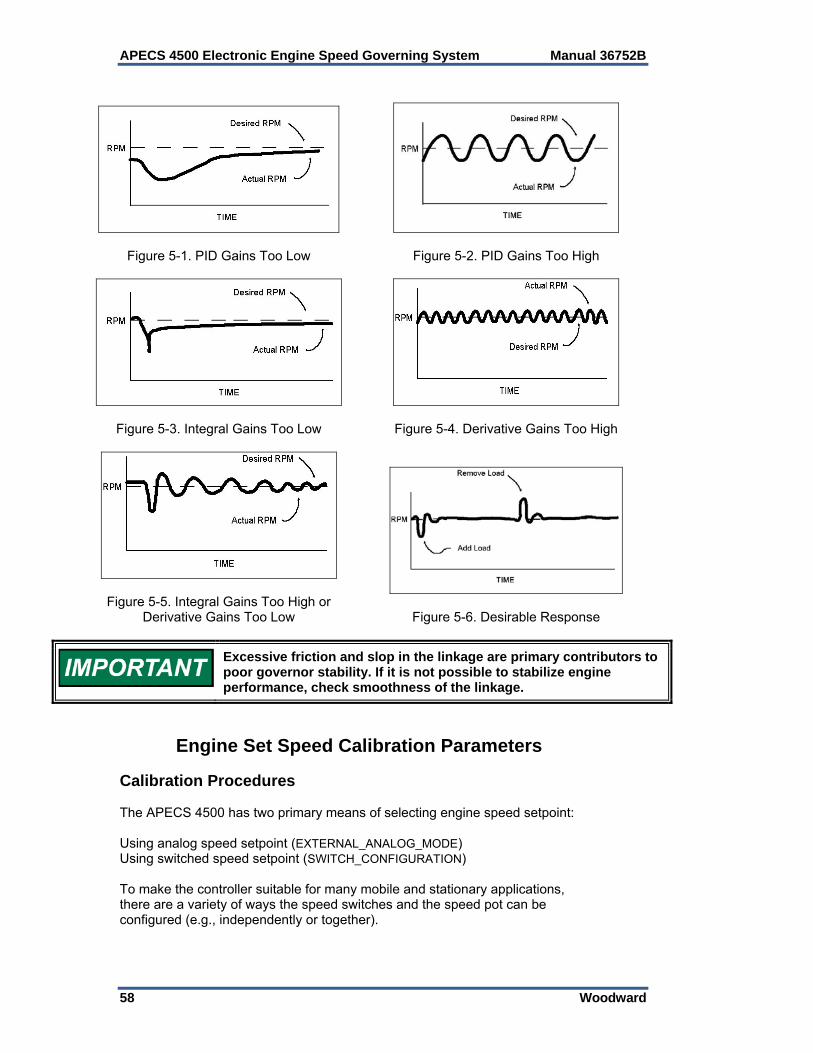
APECS 4500 Electronic Engine Speed Governing System Manual 36752B
58 Woodward
Figure 5-1. PID Gains Too Low
Figure 5-2. PID Gains Too High
Figure 5-3. Integral Gains Too Low
Figure 5-4. Derivative Gains Too High
Figure 5-5. Integral Gains Too High or Derivative Gains Too Low
Figure 5-6. Desirable Response
Excessive friction and slop in the linkage are primary contributors to poor governor stability. If it is not possible to stabilize engine performance, check smoothness of the linkage.
Engine Set Speed Calibration Parameters Calibration Procedures The APECS 4500 has two primary means of selecting engine speed setpoint: Using analog speed setpoint (EXTERNAL_ANALOG_MODE) Using switched speed setpoint (SWITCH_CONFIGURATION) To make the controller suitable for many mobile and stationary applications, there are a variety of ways the speed switches and the speed pot can be configured (e.g., independently or together).

Manual 36752B APECS 4500 Electronic Engine Speed Governing System
Woodward 59
Calibration Parameters Needing Configuration: The two primary parameters are: EXTERNAL_ANALOG_MODE This is the main parameter that defines how the analog APP input is interpreted for selecting desired engine set speed. Speed selection may be based on the analog input, the speed select switches, or a combination of the two. See Table 5-2, External Analog Input Modes. SWITCH_CONFIGURATION This parameter is used to let the software know how the user has configured the speed switch inputs. Calibrate SWITCH_CONFIGURATION according to the selected speed mode. There are five switch configurations available: Single Speed, Two Speed, Three Speed, Four Speed, and Variable Speed. See Table 5, Switch Configuration Modes. Parameters Used with the Two Primary Parameters: BRAKE_DELAY When external analog mode is set to 23, this parameter is used to specify the delay, in seconds, for automatic return to idle once the IVS input indicates no load on the engine. Range: 0-31.875 seconds. Once the timer times out, SET_SPEED_MIN will be commanded, regardless of whether the controller is in pedal mode or PTO mode. RAMP_DOWN_RATE Rate at which command engine speed decreases from one set point to a lower set point (rpm/second) RAMP_UP_RATE Rate at which commanded engine speed increases from one set point to a higher set point (rpm/second) SET_SPEED_1 Preset engine speed 1 (rpm). Used when SWITCH_CONFIGURATION = 1-4 SET_SPEED_2 Preset engine speed 2 (rpm). Used when SWITCH_CONFIGURATION = 2-4 SET_SPEED_3 Preset engine speed 3 (rpm). Used when SWITCH_CONFIGURATION = 3-4 SET_SPEED_4 Preset engine speed 4 (rpm). Used when SWITCH_CONFIGURATION = 4 SET_SPEED_MAX Highest engine speed command possible when using push-button switches to ramp engine speed up (rpm). (SWITCH_CONFIGURATION = 5) Also used to specify the maximum rpm commanded with an analog input.
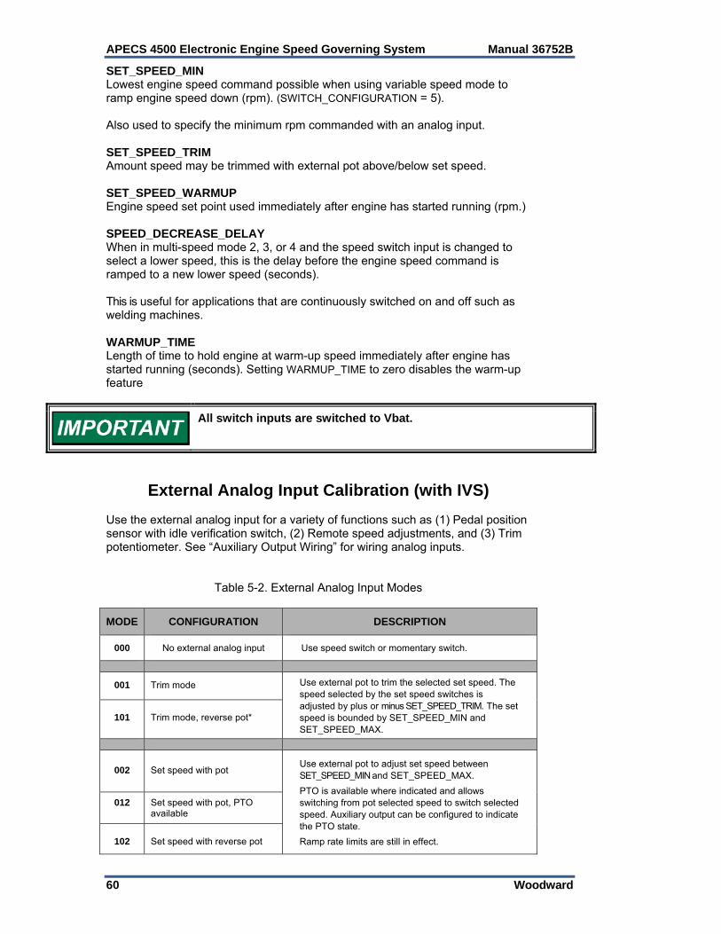
APECS 4500 Electronic Engine Speed Governing System Manual 36752B
60 Woodward
SET_SPEED_MIN Lowest engine speed command possible when using variable speed mode to ramp engine speed down (rpm). (SWITCH_CONFIGURATION = 5). Also used to specify the minimum rpm commanded with an analog input. SET_SPEED_TRIM Amount speed may be trimmed with external pot above/below set speed. SET_SPEED_WARMUP Engine speed set point used immediately after engine has started running (rpm.) SPEED_DECREASE_DELAY When in multi-speed mode 2, 3, or 4 and the speed switch input is changed to select a lower speed, this is the delay before the engine speed command is ramped to a new lower speed (seconds). This is useful for applications that are continuously switched on and off such as welding machines. WARMUP_TIME Length of time to hold engine at warm-up speed immediately after engine has started running (seconds). Setting WARMUP_TIME to zero disables the warm-up feature
All switch inputs are switched to Vbat.
External Analog Input Calibration (with IVS) Use the external analog input for a variety of functions such as (1) Pedal position sensor with idle verification switch, (2) Remote speed adjustments, and (3) Trim potentiometer. See “Auxiliary Output Wiring” for wiring analog inputs.
Table 5-2. External Analog Input Modes
MODE CONFIGURATION DESCRIPTION
000 No external analog input Use speed switch or momentary switch.
001 Trim mode Use external pot to trim the selected set speed. The speed selected by the set speed switches is adjusted by plus or minus SET_SPEED_TRIM. The set speed is bounded by SET_SPEED_MIN and SET_SPEED_MAX.
101 Trim mode, reverse pot*
002 Set speed with pot Use external pot to adjust set speed between SET_SPEED_MIN and SET_SPEED_MAX.
PTO is available where indicated and allows switching from pot selected speed to switch selected speed. Auxiliary output can be configured to indicate the PTO state.
Ramp rate limits are still in effect.
012 Set speed with pot, PTO available
102 Set speed with reverse pot
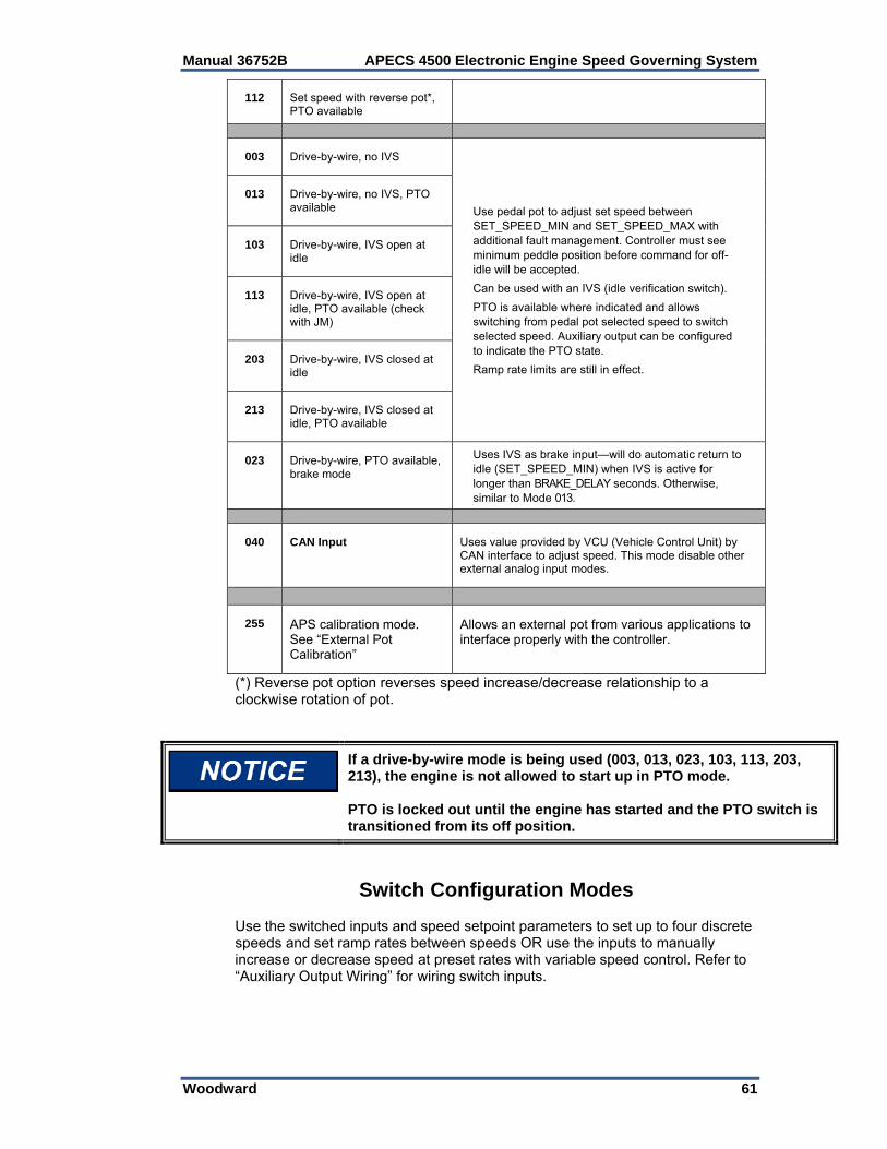
Manual 36752B APECS 4500 Electronic Engine Speed Governing System
Woodward 61
112 Set speed with reverse pot*, PTO available
003 Drive-by-wire, no IVS
Use pedal pot to adjust set speed between SET_SPEED_MIN and SET_SPEED_MAX with additional fault management. Controller must see minimum peddle position before command for off-idle will be accepted.
Can be used with an IVS (idle verification switch).
PTO is available where indicated and allows switching from pedal pot selected speed to switch selected speed. Auxiliary output can be configured to indicate the PTO state.
Ramp rate limits are still in effect.
013 Drive-by-wire, no IVS, PTO available
103 Drive-by-wire, IVS open at idle
113 Drive-by-wire, IVS open at idle, PTO available (check with JM)
203 Drive-by-wire, IVS closed at idle
213 Drive-by-wire, IVS closed at idle, PTO available
023 Drive-by-wire, PTO available, brake mode
Uses IVS as brake input—will do automatic return to idle (SET_SPEED_MIN) when IVS is active for longer than BRAKE_DELAY seconds. Otherwise, similar to Mode 013.
040 CAN Input Uses value provided by VCU (Vehicle Control Unit) by CAN interface to adjust speed. This mode disable other external analog input modes.
255 APS calibration mode. See “External Pot Calibration”
Allows an external pot from various applications to interface properly with the controller.
(*) Reverse pot option reverses speed increase/decrease relationship to a clockwise rotation of pot.
If a drive-by-wire mode is being used (003, 013, 023, 103, 113, 203, 213), the engine is not allowed to start up in PTO mode. PTO is locked out until the engine has started and the PTO switch is transitioned from its off position.
Switch Configuration Modes Use the switched inputs and speed setpoint parameters to set up to four discrete speeds and set ramp rates between speeds OR use the inputs to manually increase or decrease speed at preset rates with variable speed control. Refer to “Auxiliary Output Wiring” for wiring switch inputs.

APECS 4500 Electronic Engine Speed Governing System Manual 36752B
62 Woodward
Table 5-3. Switch Configuration Modes
CONFIGURATION MODE
DESCRIPTION
= 1: SINGLE SPEED
A single engine speed is commanded.
The engine is started and transitions from crank mode to run mode. The commanded engine speed will increase from SET_SPEED_MIN to SET_SPEED_WARMUP at the RAMP_UP_RATE.
Engine speed remains at the warm up speed for WARMUP_TIME seconds, after which the engine speed either increases at RAMP_UP_RATE or decreases at RAMP_DOWN_RATE to SET_SPEED_1.
= 2: TWO SPEED
A switch is used to select between two set speeds.
The engine is started and transitions from crank mode to run mode. The commanded engine speed will increase from SET_SPEED_MIN to SET_SPEED_WARMUP at the RAMP_UP_RATE.
Engine speed remains at the warm up speed for WARMUP_TIME seconds, after which the engine speed either increases at RAMP_UP_RATE or decreases at RAMP_DOWN_RATE to the speed selected by the switch (SET_SPEED_1 or SET_SPEED_2). When the other speed is selected with the switch, commanded engine speed is ramped to the new set speed.
= 3: THREE SPEED
A rotary switch is used to select among three set speeds.
The engine is started and transitions from crank mode to run mode. The commanded engine speed will increase from SET_SPEED_MIN to SET_SPEED_WARMUP at the RAMP_UP_RATE.
Engine speed remains at the warm up speed for WARMUP_TIME seconds, after which the engine speed either increases at RAMP_UP_RATE or decreases at RAMP_DOWN_RATE to the speed selected by the rotary switch (SET_SPEED_1 to SET_SPEED_3). When another speed is selected with the switch, the commanded engine speed is ramped to the new set speed.
= 4: FOUR SPEED
A rotary switch with two diodes is used to select among 4 set speeds.
The engine is started and transitions from crank mode to run mode. The commanded engine speed will increase from SET_SPEED_MIN to SET_SPEED_WARMUP at the RAMP_UP_RATE.
Engine speed remains at the warm up speed for WARMUP_TIME seconds, after which the engine speed either increases at RAMP_UP_RATE or decreases at RAMP_DOWN_RATE to the speed selected by the rotary switch (SET_SPEED_1 to SET_SPEED_4). When another speed is selected with the switches, the commanded engine speed is ramped to the new set speed.
= 5: VARIABLE SPEED
A momentary switch is used to ramp desired engine speed either up or down.
The engine is started and transitions from crank mode to run mode. The commanded engine speed will increase from SET_SPEED_MIN to SET_SPEED_WARMUP at the RAMP_UP_RATE. Engine speed remains at the warm up speed for WARMUP_TIME seconds, after which the user may select a new speed by using the switches, which will either increase or decrease engine speed.
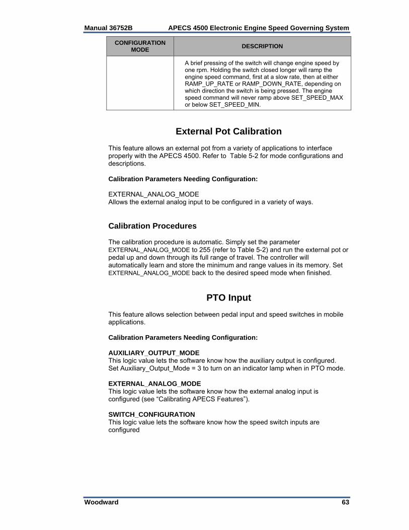
Manual 36752B APECS 4500 Electronic Engine Speed Governing System
Woodward 63
CONFIGURATION MODE
DESCRIPTION
A brief pressing of the switch will change engine speed by one rpm. Holding the switch closed longer will ramp the engine speed command, first at a slow rate, then at either RAMP_UP_RATE or RAMP_DOWN_RATE, depending on which direction the switch is being pressed. The engine speed command will never ramp above SET_SPEED_MAX or below SET_SPEED_MIN.
External Pot Calibration This feature allows an external pot from a variety of applications to interface properly with the APECS 4500. Refer to Table 5-2 for mode configurations and descriptions. Calibration Parameters Needing Configuration: EXTERNAL_ANALOG_MODE Allows the external analog input to be configured in a variety of ways. Calibration Procedures The calibration procedure is automatic. Simply set the parameter EXTERNAL_ANALOG_MODE to 255 (refer to Table 5-2) and run the external pot or pedal up and down through its full range of travel. The controller will automatically learn and store the minimum and range values in its memory. Set EXTERNAL_ANALOG_MODE back to the desired speed mode when finished.
PTO Input This feature allows selection between pedal input and speed switches in mobile applications. Calibration Parameters Needing Configuration: AUXILIARY_OUTPUT_MODE This logic value lets the software know how the auxiliary output is configured. Set Auxiliary_Output_Mode = 3 to turn on an indicator lamp when in PTO mode. EXTERNAL_ANALOG_MODE This logic value lets the software know how the external analog input is configured (see “Calibrating APECS Features”). SWITCH_CONFIGURATION This logic value lets the software know how the speed switch inputs are configured
APECS 4500 Electronic Engine Speed Governing System Manual 36752B
64 Woodward
Calibration Procedures Select the appropriate analog input mode and configure the external analog and switched inputs according to your application. In the PTO “ON” mode, select the speed with speed switches. In PTO “OFF” mode, use the pedal or the pot to adjust the speed. As a safety feature (in drive-by-wire mode only), when the engine is initially turned on, the mode is assumed to be PTO “OFF” regardless of the PTO switch setting. Users have to cycle the PTO switch “OFF” and then back “ON” to enable PTO input.
If a drive-by-wire mode is being used (003, 013, 023, 103, 113, 203, 213), the engine is not allowed to start up in PTO mode. PTO is locked out until the engine has started and the PTO switch is transitioned from its off position.
Set Speed Calibration FAQ After a power down/power up reset, does APECS remember the last speed it was using? No. The only data APECS retains after power down are the calibration parameter settings. If you are using the variable speed mode, you will have to reestablish the desired speed after the engine is restarted. However, if you are configured for one of the four set speed modes, then APECS will command the same speed on the next power up, after an optional warm up period, as long as the switches haven’t been changed. If using variable speed mode, what is the initial speed command when the engine starts? SET_SPEED_WARMUP. Even if WARMUP_TIME is set to 0, this will be the initial engine speed command. It does not change until the engine is running and the toggle switch is pressed. The toggle switch has no effect when the engine is not running. If using the 4-speed modes, what is the initial speed command when the engine starts? That depends on your use of a warm up speed. If you’re using a warm up speed, enabled by setting WARMUP_TIME to a non-zero value, then the first speed commanded will be SET_SPEED_WARMUP. If you are not using a warm up speed, disabled by setting WARMUP_TIME to zero, then the first speed commanded is selected by the speed switches. Can I command the engine to stop without powering down APECS? Yes, if you are using 2-, 3-, or 4-speed mode. Simply set one of the set speeds to 1. When you select that speed with the switch, the engine will follow the command to 1. Usually powering off the APECS unit shuts down the engine and the throttle is immediately closed. However, if you command a shutdown with the switch, and the ramp down rate is set low, the engine will be stopped in a ‘soft shutdown’ manner.
Manual 36752B APECS 4500 Electronic Engine Speed Governing System
Woodward 65
When the engine starts, does the desired engine speed jump right to the initial speed command? No. For a smoother start, desired engine speed ramps to the initial speed command from SET_SPEED_MIN. SET_SPEED_MIN is independent from the other 4 set speeds. It may be set to any value, above or below the other speeds. The recommended value for SET_SPEED_MIN is the low idle speed of the engine. Remember that SET_SPEED_MIN is also the minimum variable speed commanded when lowering engine speed with the toggle switch.
Speed Input Configuration Parameters Calibration Procedures SPEED_TYPE electrically configures the input circuitry for the speed input type and also specifies how electrical noise is to be detected and rejected. PULSES_PER_UPDATE and PULSES_PER_REV are factory set to prevent the unit from calculating an engine speed and driving the actuator. These two parameters must be calibrated to a non-zero value before normal APECS operation can begin. Calibration Parameters Needing Configuration: SPEED_TYPE Factory set for a mag pickup. This parameter electrically configures the input circuitry for the speed input type and also specifies how electrical noise is to be detected and rejected. Recommended values are as follows: Mag Pickup: 128 Coil Ignition: 2 Magneto Ignition: 3 Hall Effect Sensor: 131 PULSES_PER_UPDATE The number of pulses received by the controller between engine speed calculations and updates. The fewer the pulses, the faster the update rate and the lower the resolution; the greater the pulses, the greater the averaging effect on calculated engine speed. Factory set to zero. Must be non-zero to operate. PULSES_PER_REV The number of teeth on the engine speed pickup wheel (mag pickup input and Hall Effect sensor), or the number of spark pulses per engine rev (ignition input). To figure out the pulses per revolution, you must determine the kind of speed signal input used on your application: Magnetic Pickup Input or Hall Effect Sensor Pulses per revolution = number of teeth on the flywheel Woodward Mini-Gen® Signal Generator Pulses per revolution = 0.5 x drive ratio if Mini-Gen is driven at other than crankshaft speed
APECS 4500 Electronic Engine Speed Governing System Manual 36752B
66 Woodward
Spark Ignition Input Pulses per revolution = 1 for single cylinder engine with magneto and one wasted spark Pulses per revolution = number of cylinders / 2 for multi cylinder engine with distributor PULSES_PER_REV FAQ How does PULSES_PER_REV work when using the ignition signal for engine speed? When an ignition signal is used to detect engine speed, the input pulses relate directly to cylinder firing events rather than teeth on a flywheel. The controller measures the time between the input pulses from the ignition. To accurately calculate engine speed, it must know how many ignition pulses are occurring in each engine revolution; this is PULSES_PER_REV. The number of ignition pulses per engine revolution will vary depending on the engine type. Factors that must be known include: how many cylinders the engine has, whether there is a distributor, and if a waste spark is generated. Are there any general guidelines? Yes. Single cylinder engines typically use a magneto with a firing spark and a wasted spark. The firing spark occurs at the end of the compression stroke, once every 2 engine revs. The wasted spark occurs at the end of the exhaust stroke, 360º later. Therefore, the signal from the ignition will have one pulse per engine revolution. PULSES_PER_REV = 1. With multi-cylinder engines using a distributor, the primary ignition signal will have one pulse for every cylinder-firing event. Since each cylinder is fired every 2 revs, PULSES_PER_REV = number of cylinders ÷ 2. PULSES_PER_REV must be an integer; no half pulses allowed. The ignition signal from a 3-cylinder engine will have 3 pulses per 2 engine revs, which works out to 1.5 pulses per engine rev. To work around this situation, assign PULSES_PER_REV = 3. Then the calculated engine speed will be exactly half actual speed. If the engine is operating at 1800 rpm, displayed engine speed will be 900 rpm. Therefore all set speeds must be half of the actual target speed.
If you forget and set the desired speed to 1800 rpm, the engine will speed up to 3600 rpm in order to reach the target.
Engine Start Calibration Parameters This section covers parameters for engine start calibration Glowplug Control On a command from an auto-start switch (using PTO input), the auxiliary output can be configured to turn on a glowplug relay before engaging the autocrank relay. The glowplug relay will remain on until the engine starts or until the autocrank sequence completes the maximum permissible number of crank cycles. This feature is useful for remote operation of certain engines or applications.

Manual 36752B APECS 4500 Electronic Engine Speed Governing System
Woodward 67
Calibration Parameters Needing Configuration: AUXILIARY_OUTPUT_MODE This parameter is used to let the software know how the auxiliary output of APECS 4500 is to be configured. Set to a value of 6 for glowplug control. See “Auxiliary Outputs” for settings. AUXILIARY_OUTPUT_2_MODE This parameter is used to let the software know how auxiliary output #2 of APECS 4500 is to be configured. Set to a value of 6 for glowplug control. See “Auxiliary Outputs” for settings. GLOWPLUG_TIME This parameter specifies the pre-heat time, in seconds, before the autocrank relay is engaged. Calibration Procedures The glowplug feature is enabled by setting AUXILIARY_OUTPUT_MODE or AUXILIARY_OUTPUT_2_MODE to 6. When the auto-start switch is made, the glowplug output becomes active for GLOWPLUG_TIME (sec) before the autocrank relay is engaged. Autocrank On a command from an auto-start switch (using PTO input), an engine will go through an autocrank sequence (using auxiliary output). This feature is useful for remote operation of certain engines or applications.
To effectively use the autocrank feature, the actuator should be able to stop the engine, otherwise an ignition cutoff type system must be provided.
Calibration Parameters Needing Configuration: AUTOCRANK_CRANK_TIME Specifies the maximum time, in seconds that the engine will crank. If the engine starts during the crank period, engine cranking will be terminated. Range: 0-31.9 seconds. AUTOCRANK_MAX_TRIES Maximum number of crank/rest cycles before autocrank logic stops trying to start the engine and flags a fault. Range: 0-255. AUTOCRANK_REST_TIME If the engine does not start during the cranking interval, cranking will be disabled for AUTOCRANK_REST_TIME seconds in order to permit the starter motor to cool. Range: 0-31.9 seconds. AUXILIARY_OUTPUT_MODE This parameter is used to let the software know how the auxiliary output of APECS 4500 is to be configured. See “Auxiliary Outputs” for settings. AUXILIARY_OUTPUT_2_MODE This parameter is used to let the software know how auxiliary output #2 of APECS 4500 is to be configured. See “Auxiliary Outputs” for settings.
APECS 4500 Electronic Engine Speed Governing System Manual 36752B
68 Woodward
Calibration Procedures The autocrank feature is enabled by setting AUXILIARY_OUTPUT_MODE or AUXILIARY_OUTPUT_2_MODE to 4. PTO is not available with autocrank. When the auto-start switch is made, the autocrank output waits GLOWPLUG_TIME seconds then becomes active for AUTOCRANK_CRANK_TIME (sec) or until the engine starts. If the engine does not start, then the output goes inactive for AUTOCRANK_REST_TIME (sec), and then another crank attempt is made. The sequence is repeated for AUTOCRANK_MAX_TRIES. If the engine has not started after the maximum crank attempts have been made, a fault is flagged. When the auto-start switch is turned off, actuator duty cycle is set to zero to shut down the engine. Engine Cranking The engine cranking parameters control how APECS will drive the actuator during cranking. Calibration Parameters Needing Configuration: CRANK_2_RUN Speed transition point indicating engine has gone from crank mode to run mode (rpm). Once engine rpm rises above CRANK_2_RUN rpm, it is assumed that the engine is in run mode. CRANK_DUTY_CYCLE The fixed duty cycle used to drive the actuator when the engine is cranking (percent). May be calibrated to a maximum duty cycle for diesel engines that require full rack for starting, or a minimum duty cycle for some spark-ignition engines that require closed throttle for starting.
This parameter is preset to a value that will work with most engines and applications. Entering new values for these parameters is optional.
KEY_ON_DUTY_TIME The actuator will be driven at CRANK_DUTY_CYCLE following key-on reset for KEY_ON_DUTY_TIME (in seconds) while there is no input speed signal. Once a valid speed signal is detected, normal operation ensues. This is useful for applications that do not generate a speed input signal at crank (e.g. genset which senses engine speed from the generator output). When using this feature, the duty cycle does not cut back until a valid input speed signal is seen, or the timeout period is up. If there is never a valid input speed, the actuator will continue to be driven at CRANK_DUTY_CYCLE even if the engine is running. This could lead to an overspeed situation. Default value: 0 Calibration Procedures CRANK_DUTY_CYCLE may be calibrated to a maximum duty cycle for diesel engines that require full rack for starting, or a mid-range duty cycle for some spark-ignition engines that require a partially open throttle for starting.
Manual 36752B APECS 4500 Electronic Engine Speed Governing System
Woodward 69
In run mode, control is closed-loop; the actuator is driven as necessary to maintain the set desired speed. Setting KEY_ON_DUTY_TIME (seconds) to a non-zero value will cause the actuator to be driven to the crank duty cycle, even if no engine speed signal is present. The actuator is energized at key-on reset for the set amount of time. This may be useful for generator applications where it is desirable to sense engine speed from the generator frequency. To keep speed voltage below 75 Vrms, a step down transformer may be necessary. When this feature is used, it is especially important to have a redundant overspeed protection device because a broken speed input wire could cause the engine to run at wide open throttle for up to KEY_ON_DUTY_TIME.
Diagnostics Calibration Parameters This section covers diagnostic calibration parameter configuration. Engine Protection Input User selectable input to protect against adverse conditions such as high coolant temperature or low oil pressure. In case of oil pressure, allows the engine time for oil pressure to rise following startup. Calibration Parameters Needing Configuration: ENGINE_PRTCT_RUN_TIME The time, in seconds, that the engine must be running before the engine protection logic begins to monitor the engine protection input. This permits the APECS 4500 to automatically account for oil pressure switches and similar devices that indicate a fault condition when the engine is not running. Setting ENGINE_PRTCT_RUN_TIME to 8000 or more will disable the engine protection option. ENGINE_PROTECT_TIME The amount of time spent with the engine protection input made before the actuator is shut down (ms). The APECS 4500 has a dedicated engine protection switch input. The engine protection feature must be enabled by setting ENGINE_PRTCT_RUN_TIME to a value less than 8000. Once the engine has been in run mode longer than ENGINE_PRTCT_RUN_TIME, if the engine protection input is grounded for longer than ENGINE_PROTECT_TIME milliseconds, the governor will go into shutdown mode and the fault lamp will flash a four code. Calibration Procedures ENGINE_PRTCT_RUN_TIME is set to the time in seconds the engine must be running before a grounded signal on the engine protection input will be serviced. If ENGINE_PRTCT_RUN_TIME is set to 0, then the input will also inhibit any actuator duty cycle at cranking if the engine protection switch contacts are closed. The input must be made before engine shutdown (actuator output) will begin.
APECS 4500 Electronic Engine Speed Governing System Manual 36752B
70 Woodward
If the engine has been running longer than ENGINE_PRTCT_RUN_TIME, and the engine protection input has been made continually (not intermittently), then the actuator will be shutdown and a fault will be generated. The lamp on the APECS unit will flash to indicate the fault, and the fault will be cleared when the engine is restarted. Overspeed / Underspeed Protection This feature incorporates user selectable overspeed and underspeed parameters that affect engine shutdown. Calibration Parameters Needing Configuration: OVERSPEED_RPM Critical engine speed used for overspeed protection (rpm). Set OVERSPEED_RPM to zero if overspeed protection is not desired. Normal closed-loop governing will decrease the duty cycle to the actuator any time engine speed is above the set point. Overspeed protection immediately shuts off the actuator when an overspeed condition is detected. Engine speed must be brought back to zero before the actuator is driven again. Setting OVERSPEED_RPM to zero disables the overspeed protection feature. Default value: 0. UNDERSPEED_RPM Minimum engine speed used for underspeed shutdown (rpm). Normal closed-loop governing will increase the duty cycle to the actuator any time engine speed is below the set point. Underspeed shutdown immediately shuts off the actuator when an underspeed condition is detected. Engine speed must be brought back to zero before the actuator is driven again. Setting UNDERSPEED_RPM to zero disables the underspeed protection feature. UNDERSPEED_RUN_TIME Amount of time the engine must be in run mode before underspeed shut down is activated (seconds). Calibration Procedures The overspeed protection feature immediately shuts off the actuator when the engine runs above OVERSPEED_RPM. Setting the OVERSPEED_RPM value to zero disables this feature. The underspeed protection feature immediately shuts off the actuator when the engine rpm runs under the UNDERSPEED_RPM value. Set the UNDERSPEED_RUN_TIME value as desired. Setting the UNDERSPEED_RPM value to zero disables the underspeed protection feature. When an engine overspeed/underspeed condition is detected, the engine protection control logic causes: (1) the actuator duty cycle to go immediately to zero (2) a fault code activation which is signified by LED flashing. After engine protection control logic tripping, the fault code will continue to flash the LED. This signifies to the user that the engine stopped due to overspeed or underspeed engine conditions. The engine may later be restarted without resetting the unit; this action will cause the fault code to reset and the LED will then stop flashing.
Manual 36752B APECS 4500 Electronic Engine Speed Governing System
Woodward 71
Overspeed FAQ How Does Overspeed Work? The APECS 4500 has the diagnostic capability to detect and react to an overspeed condition. The feature uses two programmable parameters, OVERSPEED_RPM and OVERSPEED_TIME. Overspeed feature immediately shuts off the actuator when the engine runs above OVERSPEED_RPM for OVERSPEED_TIME. OVERSPEED_TIME is used to adjust the sensitivity. A large value will delay the shut down, and a small value will hasten it. A value as small as zero can be used, which means that the first occurrence of engine speed being over OVERSPEED_RPM will result in a shut down. This is too sensitive and the engine could be shut down in the unlikely event that noise on the speed signal input caused a high miscalculation of engine speed. A minimum value of 250 ms is recommended. The user should realistically determine an overspeed tolerance time. When an overspeed condition is detected, the duty cycle goes immediately to zero. This should stop the engine or at least drive it to minimum speed. A fault code is generated, and the LED flashes. The fault will continue to flash so that the user is made aware of why the engine stopped. The engine may be restarted without resetting the unit. The fault will then recover and stop flashing. By default, overspeed is disabled. This is because a properly tuned PID governor will decrease the duty cycle to the actuator any time engine speed is above the set point. So ordinarily, overspeed is not necessary. It is disabled by setting OVERSPEED_RPM to zero. However, if a user feels the need for a more aggressive response to an overspeed condition, the overspeed diagnostic feature may be used.
Actuator Output Calibration Parameters This section covers actuator output calibration parameter configuration. Actuator Current Protection The actuator current protection feature limits current to the actuator in order to protect the actuator from overheating. Current protection limits the steady-state current to the actuator, but allows higher currents for short durations. There are two types of current limiting: 1. Soft limit (can be exceeded for a brief period of time). 2. Hard limit (can never be exceeded)—provides short-circuit protection for the
driver. SOFT LIMIT Actuator current is monitored using display parameter actuator_fdbk_sense. If actuator_fdbk_sense exceeds HIGH_ACTFDBK_LMX for HIGH_ACTFDBK_TIME (in seconds), then the duty cycle maximum limit is ramped down until the current is below the limit threshold.
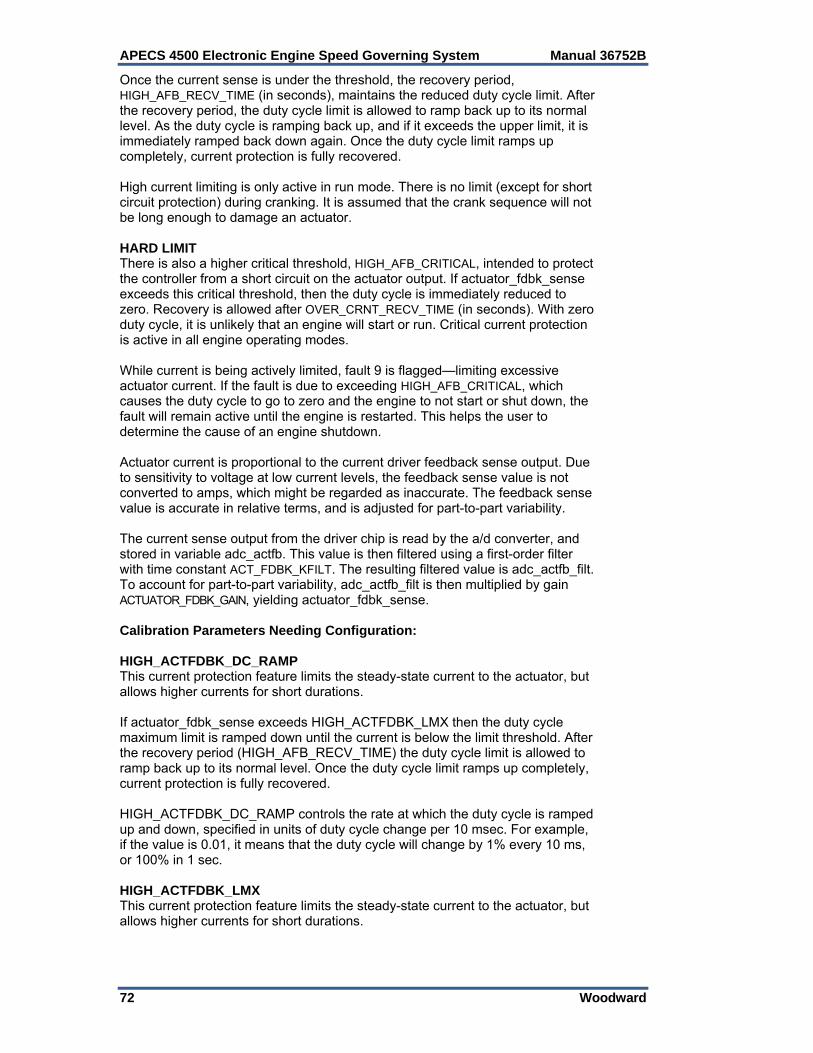
APECS 4500 Electronic Engine Speed Governing System Manual 36752B
72 Woodward
Once the current sense is under the threshold, the recovery period, HIGH_AFB_RECV_TIME (in seconds), maintains the reduced duty cycle limit. After the recovery period, the duty cycle limit is allowed to ramp back up to its normal level. As the duty cycle is ramping back up, and if it exceeds the upper limit, it is immediately ramped back down again. Once the duty cycle limit ramps up completely, current protection is fully recovered. High current limiting is only active in run mode. There is no limit (except for short circuit protection) during cranking. It is assumed that the crank sequence will not be long enough to damage an actuator. HARD LIMIT There is also a higher critical threshold, HIGH_AFB_CRITICAL, intended to protect the controller from a short circuit on the actuator output. If actuator_fdbk_sense exceeds this critical threshold, then the duty cycle is immediately reduced to zero. Recovery is allowed after OVER_CRNT_RECV_TIME (in seconds). With zero duty cycle, it is unlikely that an engine will start or run. Critical current protection is active in all engine operating modes. While current is being actively limited, fault 9 is flagged—limiting excessive actuator current. If the fault is due to exceeding HIGH_AFB_CRITICAL, which causes the duty cycle to go to zero and the engine to not start or shut down, the fault will remain active until the engine is restarted. This helps the user to determine the cause of an engine shutdown. Actuator current is proportional to the current driver feedback sense output. Due to sensitivity to voltage at low current levels, the feedback sense value is not converted to amps, which might be regarded as inaccurate. The feedback sense value is accurate in relative terms, and is adjusted for part-to-part variability. The current sense output from the driver chip is read by the a/d converter, and stored in variable adc_actfb. This value is then filtered using a first-order filter with time constant ACT_FDBK_KFILT. The resulting filtered value is adc_actfb_filt. To account for part-to-part variability, adc_actfb_filt is then multiplied by gain ACTUATOR_FDBK_GAIN, yielding actuator_fdbk_sense. Calibration Parameters Needing Configuration: HIGH_ACTFDBK_DC_RAMP This current protection feature limits the steady-state current to the actuator, but allows higher currents for short durations. If actuator_fdbk_sense exceeds HIGH_ACTFDBK_LMX then the duty cycle maximum limit is ramped down until the current is below the limit threshold. After the recovery period (HIGH_AFB_RECV_TIME) the duty cycle limit is allowed to ramp back up to its normal level. Once the duty cycle limit ramps up completely, current protection is fully recovered. HIGH_ACTFDBK_DC_RAMP controls the rate at which the duty cycle is ramped up and down, specified in units of duty cycle change per 10 msec. For example, if the value is 0.01, it means that the duty cycle will change by 1% every 10 ms, or 100% in 1 sec. HIGH_ACTFDBK_LMX This current protection feature limits the steady-state current to the actuator, but allows higher currents for short durations.
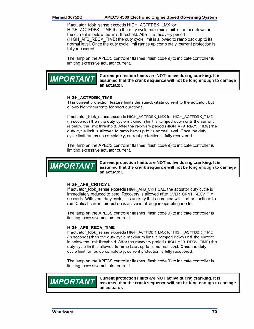
Manual 36752B APECS 4500 Electronic Engine Speed Governing System
Woodward 73
If actuator_fdbk_sense exceeds HIGH_ACTFDBK_LMX for HIGH_ACTFDBK_TIME then the duty cycle maximum limit is ramped down until the current is below the limit threshold. After the recovery period (HIGH_AFB_RECV_TIME) the duty cycle limit is allowed to ramp back up to its normal level. Once the duty cycle limit ramps up completely, current protection is fully recovered. The lamp on the APECS controller flashes (flash code 9) to indicate controller is limiting excessive actuator current.
Current protection limits are NOT active during cranking. It is assumed that the crank sequence will not be long enough to damage an actuator.
HIGH_ACTFDBK_TIME This current protection feature limits the steady-state current to the actuator, but allows higher currents for short durations. If actuator_fdbk_sense exceeds HIGH_ACTFDBK_LMX for HIGH_ACTFDBK_TIME (in seconds) then the duty cycle maximum limit is ramped down until the current is below the limit threshold. After the recovery period (HIGH_AFB_RECV_TIME) the duty cycle limit is allowed to ramp back up to its normal level. Once the duty cycle limit ramps up completely, current protection is fully recovered. The lamp on the APECS controller flashes (flash code 9) to indicate controller is limiting excessive actuator current.
Current protection limits are NOT active during cranking. It is assumed that the crank sequence will not be long enough to damage an actuator.
HIGH_AFB_CRITICAL If actuator_fdbk_sense exceeds HIGH_AFB_CRITICAL, the actuator duty cycle is immediately reduced to zero. Recovery is allowed after OVER_CRNT_RECV_TIM seconds. With zero duty cycle, it is unlikely that an engine will start or continue to run. Critical current protection is active in all engine operating modes. The lamp on the APECS controller flashes (flash code 9) to indicate controller is limiting excessive actuator current. HIGH_AFB_RECV_TIME If actuator_fdbk_sense exceeds HIGH_ACTFDBK_LMX for HIGH_ACTFDBK_TIME (in seconds) then the duty cycle maximum limit is ramped down until the current is below the limit threshold. After the recovery period (HIGH_AFB_RECV_TIME) the duty cycle limit is allowed to ramp back up to its normal level. Once the duty cycle limit ramps up completely, current protection is fully recovered. The lamp on the APECS controller flashes (flash code 9) to indicate controller is limiting excessive actuator current.
Current protection limits are NOT active during cranking. It is assumed that the crank sequence will not be long enough to damage an actuator.
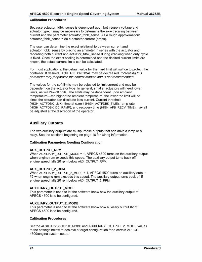
APECS 4500 Electronic Engine Speed Governing System Manual 36752B
74 Woodward
Calibration Procedures Because actuator_fdbk_sense is dependent upon both supply voltage and actuator type, it may be necessary to determine the exact scaling between current and the parameter actuator_fdbk_sense. As a rough approximation: actuator_fdbk_sense = 80 × actuator current (amps). The user can determine the exact relationship between current and actuator_fdbk_sense by placing an ammeter in series with the actuator and recording both current and actuator_fdbk_sense during cranking when duty cycle is fixed. Once the exact scaling is determined and the desired current limits are known, the actual current limits can be calculated. For most applications, the default value for the hard limit will suffice to protect the controller. If desired, HIGH_AFB_CRITICAL may be decreased. Increasing this parameter may jeopardize the control module and is not recommended. The values for the soft limits may be adjusted to limit current and may be dependent on the actuator type. In general, smaller actuators will need lower limits, as will 24-volt coils. The limits may be dependent upon ambient temperature—the higher the ambient temperature, the lower the limit will be since the actuator can dissipate less current. Current threshold (HIGH_ACTFDBK_LMX), time at current (HIGH_ACTFDBK_TIME), ramp rate (HIGH_ACTFDBK_DC_RAMP), and recovery time (HIGH_AFB_RECV_TIME) may all be adjusted at the discretion of the operator. Auxiliary Outputs The two auxiliary outputs are multipurpose outputs that can drive a lamp or a relay. See the sections beginning on page 16 for wiring information. Calibration Parameters Needing Configuration: AUX_OUTPUT_RPM When AUXILIARY_OUTPUT_MODE = 1, APECS 4500 turns on the auxiliary output when engine rpm exceeds this speed. The auxiliary output turns back off if engine speed falls 20 rpm below AUX_OUTPUT_RPM. AUX_OUTPUT_2_RPM When AUXILIARY_OUTPUT_2_MODE = 1, APECS 4500 turns on auxiliary output #2 when engine rpm exceeds this speed. The auxiliary output turns back off if engine speed falls 20 rpm below AUX_OUTPUT_2_RPM. AUXILIARY_OUTPUT_MODE This parameter is used to let the software know how the auxiliary output of APECS 4500 is to be configured. AUXILIARY_OUTPUT_2_MODE This parameter is used to let the software know how auxiliary output #2 of APECS 4500 is to be configured. Calibration Procedures Set the AUXILIARY_OUTPUT_MODE and AUXILIARY_OUTPUT_2_MODE values to the settings below to achieve a target configuration for a certain APECS 4500/engine system setup.
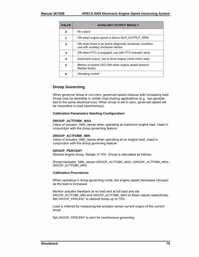
Manual 36752B APECS 4500 Electronic Engine Speed Governing System
Woodward 75
VALUE AUXILIARY OUTPUT RESULT
0 No output
1 ON when engine speed is above AUX_OUTPUT_RPM
2 ON when there is an active diagnostic shutdown condition; use with auxiliary shutdown device
3 ON when PTO is engaged; use with PTO indicator lamp
4 Autocrank output, use to drive engine crank motor relay
5 Mimics on-board LED (ON when engine speed present, flashes faults)
6 Glowplug control
Droop Governing When governor droop is non-zero, governed speed reduces with increasing load. Droop may be desirable in certain load sharing applications (e.g., two gensets tied to the same electrical bus). When droop is set to zero, governed speed will be insensitive to load (isochronous). Calibration Parameters Needing Configuration: DROOP_ACTFDBK_MAX Value of actuator_fdbk_sense when operating at maximum engine load. Used in conjunction with the droop governing feature. DROOP_ACTFDBK_MIN Value of actuator_fdbk_sense when operating at no engine load. Used in conjunction with the droop governing feature. DROOP_PERCENT Desired engine droop. Range: 0-15%. Droop is calculated as follows: Droop=(actuator_fdbk_sense–DROOP_ACTFDBK_MIN) / (DROOP_ACTFDBK_MAX–DROOP_ACTFDBK_MIN) Calibration Procedures When operating in droop governing mode, the engine speed decreases (droops) as the load is increased. Monitor actuator feedback at no load and at full load and set DROOP_ACTFDBK_MIN and DROOP_ACTFDBK_MAX to these values respectively. Set DROOP_PERCENT to desired droop up to 15%. Load is inferred by measuring the actuator sense current output of the current driver. Set DROOP_PERCENT to zero for isochronous governing.
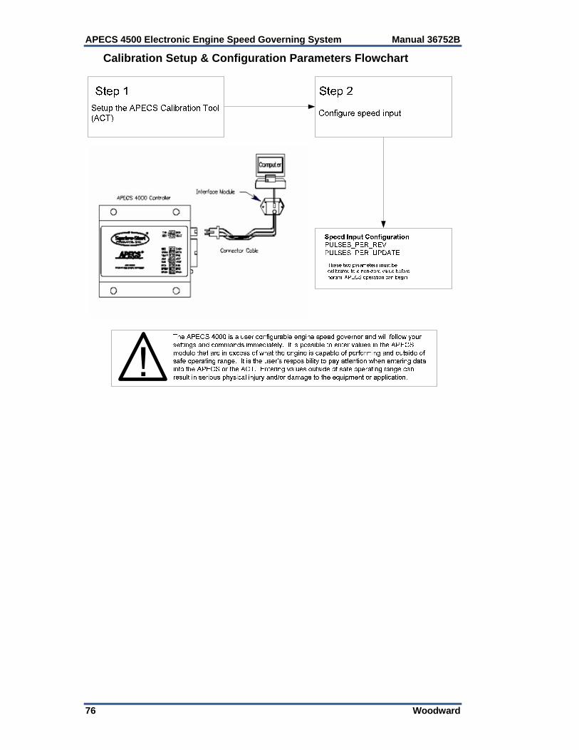
APECS 4500 Electronic Engine Speed Governing System Manual 36752B
76 Woodward
Calibration Setup & Configuration Parameters Flowchart
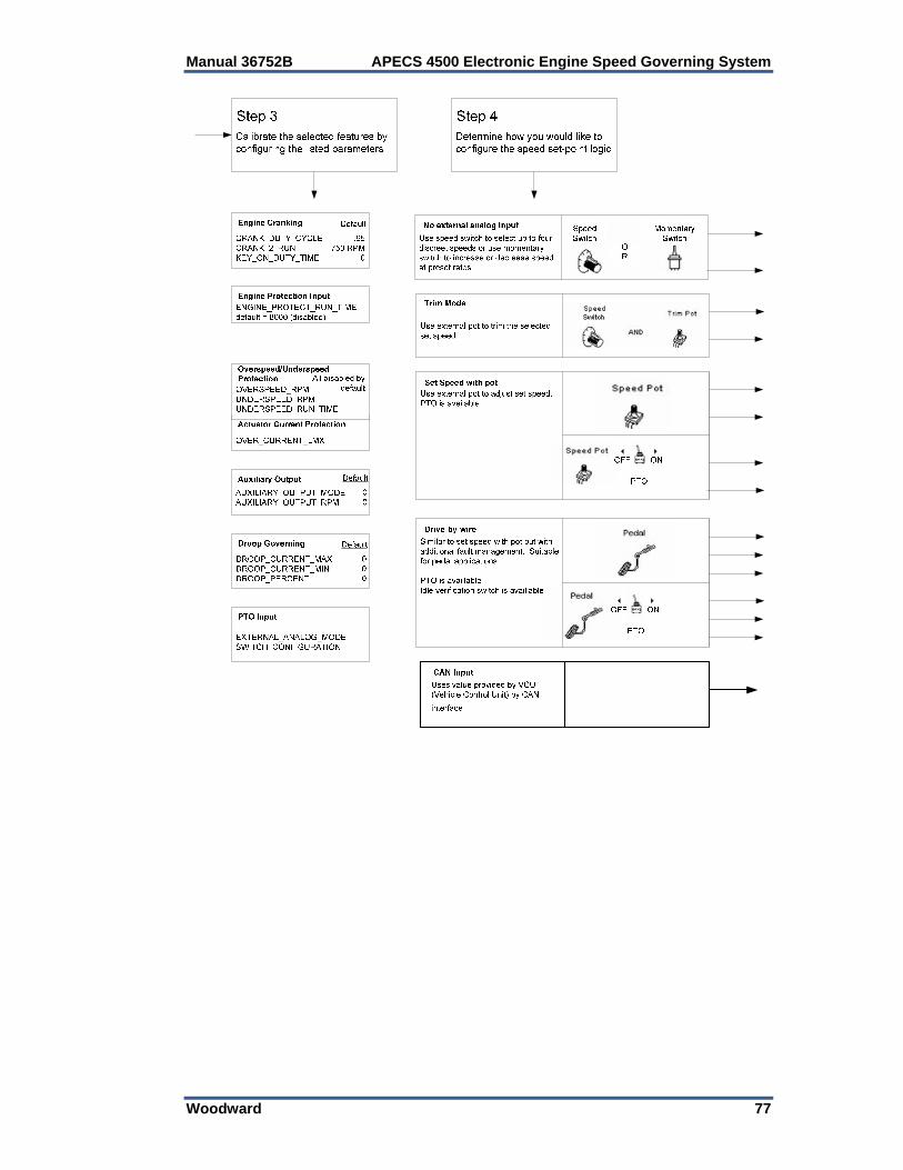
Manual 36752B APECS 4500 Electronic Engine Speed Governing System
Woodward 77
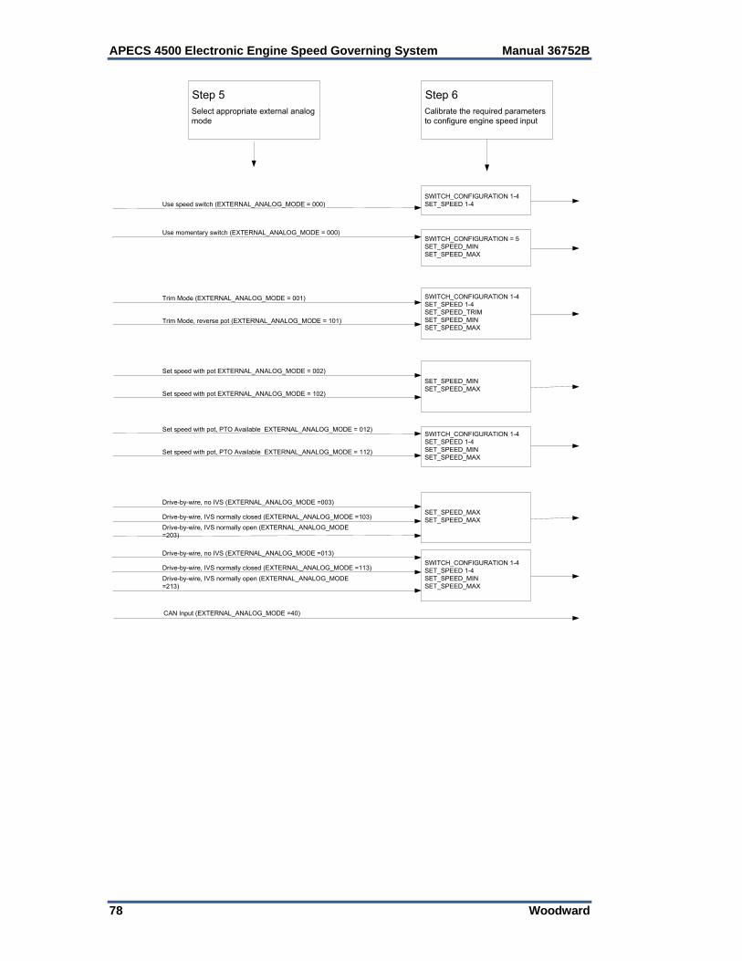
APECS 4500 Electronic Engine Speed Governing System Manual 36752B
78 Woodward
SWITCH_CONFIGURATION 1-4SET_SPEED 1-4
Step 5Select appropriate external analog mode
Step 6Calibrate the required parameters to configure engine speed input
SWITCH_CONFIGURATION = 5SET_SPEED_MINSET_SPEED_MAX
SWITCH_CONFIGURATION 1-4SET_SPEED 1-4SET_SPEED_TRIMSET_SPEED_MINSET_SPEED_MAX
Use speed switch (EXTERNAL_ANALOG_MODE = 000)
Use momentary switch (EXTERNAL_ANALOG_MODE = 000)
Trim Mode (EXTERNAL_ANALOG_MODE = 001)
Trim Mode, reverse pot (EXTERNAL_ANALOG_MODE = 101)
SET_SPEED_MINSET_SPEED_MAX
Set speed with pot EXTERNAL_ANALOG_MODE = 002)
Set speed with pot EXTERNAL_ANALOG_MODE = 102)
SWITCH_CONFIGURATION 1-4SET_SPEED 1-4SET_SPEED_MINSET_SPEED_MAX
Set speed with pot, PTO Available EXTERNAL_ANALOG_MODE = 012)
Set speed with pot, PTO Available EXTERNAL_ANALOG_MODE = 112)
SET_SPEED_MAXSET_SPEED_MAX
Drive-by-wire, no IVS (EXTERNAL_ANALOG_MODE =003)
Drive-by-wire, IVS normally open (EXTERNAL_ANALOG_MODE =203)
SWITCH_CONFIGURATION 1-4SET_SPEED 1-4SET_SPEED_MINSET_SPEED_MAX
Drive-by-wire, IVS normally closed (EXTERNAL_ANALOG_MODE =103)
Drive-by-wire, no IVS (EXTERNAL_ANALOG_MODE =013)
Drive-by-wire, IVS normally open (EXTERNAL_ANALOG_MODE =213)
Drive-by-wire, IVS normally closed (EXTERNAL_ANALOG_MODE =113)
CAN Input (EXTERNAL_ANALOG_MODE =40)
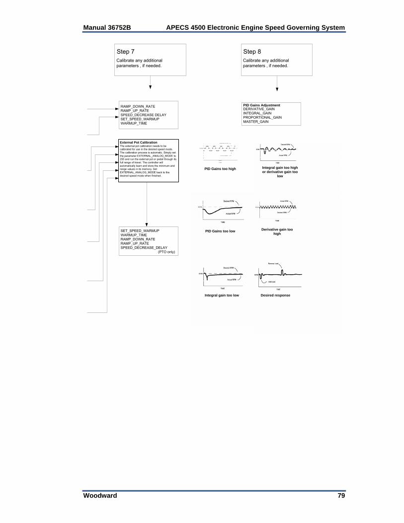
Manual 36752B APECS 4500 Electronic Engine Speed Governing System
Woodward 79
Step 7Calibrate any additional parameters , if needed.
Step 8Calibrate any additional parameters , if needed.
RAMP_DOWN_RATERAMP_UP_RATESPEED_DECREASE DELAYSET_SPEED_WARMUPWARMUP_TIME
External Pot CalibrationThe external pot calibration needs to be calibrated for use in the desired speed mode. The calibration process is automatic. Simply set the parameter EXTERNAL_ANALOG_MODE to 255 and run the external pot or pedal through it's full range of travel. The controller will automatically learn and store the minimum and range values in tits memory. Set EXTERNAL_ANALOG_MODE back to the sdesired speed mode when finished.
SET_SPEED_WARMUPWARMUP_TIMERAMP_DOWN_RATERAMP_UP_RATESPEED_DECREASE_DELAY
(PTO only)
PID Gains AdjustmentDERIVATIVE_GAININTEGRAL_GAINPROPORTIONAL_GAINMASTER_GAIN
PID Gains too low
PID Gains too high
Integral gain too low
Derivative gain too high
Integral gain too high or derivative gain too
low
Desired response
External Pot Calibration The external pot calibration needs to be calibrated for use in the desired speed mode. The calibration process is automatic. Simply set the parameter EXTERNAL_ANALOG_MODE to 255 and run the external pot or pedal through its full range of travel. The controller will automatically learn and store the minimum and range values in its memory. Set EXTERNAL_ANALOG_MODE back to the desired speed mode when finished.
APECS 4500 Electronic Engine Speed Governing System Manual 36752B
80 Woodward
Chapter 6. Troubleshooting
General Checklist Please follow the checklist below to troubleshoot your APECS controller. We recommend using a digital multimeter capable of measuring frequency and duty cycle such as a Fluke 87. 1. Check battery voltage for stability and correct value. The LED will turn on for
one second when the APECS 4500 is first powered up. 2. For magnetic pickups, check that the speed signal is at least 2 Vrms using the
AC volt settings on voltmeter. Actuator should go to full travel during cranking. The LED will illuminate when it senses an engine speed.
3. Check the actuator linkage for binding and backlash. 4. Check that the actuator has sufficient force to reach the starting and rated
load positions. 5. Confirm normal operation of engine under manual control. 6. Confirm that the load (e.g., voltage regulator on generator) is not inducing
instability. 7. Try adjusting the gains to achieve stability.
Fault Codes The APECS 4500 controller is capable of identifying certain fault conditions and alerting the user to them. A flashing LED indicates the fault conditions. The current fault code list is shown in Table 6. Please note the following: 1. When power is first applied to the controller, the LED will flash just once for
one second to indicate that the LED is working. 2. If there are multiple faults, the LED will flash them all in sequence. Count the
flash codes to determine the fault conditions or connect the Calibration Tool to observe the fault conditions. (Use the “Display Faults” option under the Monitor Menu.)
3. If there are no faults, the LED will flash once at reset and from then on
indicate the detection of engine speed. A continuous ON LED indicates that a valid engine speed is being sensed.
4. The controller will attempt to shut down for some faults and will not permit
starting after reset with faults 1, 5 and 8.
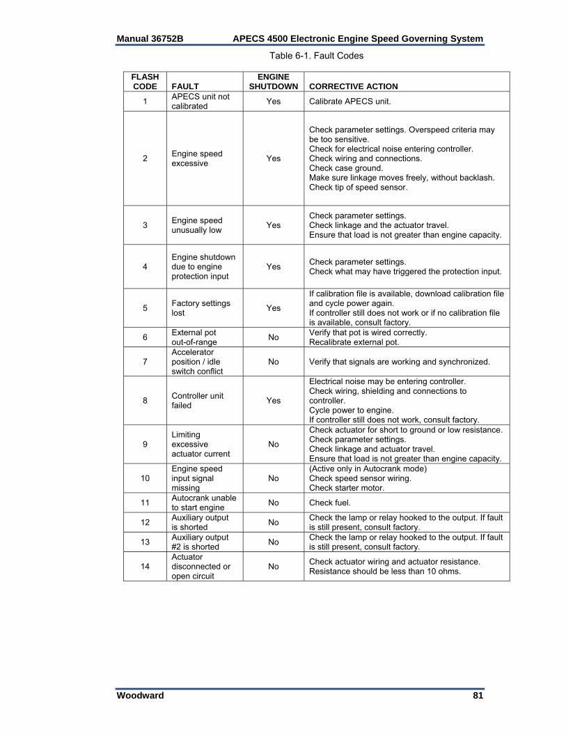
Manual 36752B APECS 4500 Electronic Engine Speed Governing System
Woodward 81
Table 6-1. Fault Codes
FLASH CODE FAULT
ENGINE SHUTDOWN CORRECTIVE ACTION
1 APECS unit not calibrated
Yes Calibrate APECS unit.
2 Engine speed excessive
Yes
Check parameter settings. Overspeed criteria may be too sensitive. Check for electrical noise entering controller. Check wiring and connections. Check case ground. Make sure linkage moves freely, without backlash. Check tip of speed sensor.
3 Engine speed unusually low
Yes Check parameter settings. Check linkage and the actuator travel. Ensure that load is not greater than engine capacity.
4 Engine shutdown due to engine protection input
Yes Check parameter settings. Check what may have triggered the protection input.
5 Factory settings lost
Yes
If calibration file is available, download calibration file and cycle power again. If controller still does not work or if no calibration file is available, consult factory.
6 External pot out-of-range
No Verify that pot is wired correctly. Recalibrate external pot.
7 Accelerator position / idle switch conflict
No Verify that signals are working and synchronized.
8 Controller unit failed
Yes
Electrical noise may be entering controller. Check wiring, shielding and connections to controller. Cycle power to engine. If controller still does not work, consult factory.
9 Limiting excessive actuator current
No
Check actuator for short to ground or low resistance. Check parameter settings. Check linkage and actuator travel. Ensure that load is not greater than engine capacity.
10 Engine speed input signal missing
No (Active only in Autocrank mode) Check speed sensor wiring. Check starter motor.
11 Autocrank unable to start engine
No Check fuel.
12 Auxiliary output is shorted
No Check the lamp or relay hooked to the output. If fault is still present, consult factory.
13 Auxiliary output #2 is shorted
No Check the lamp or relay hooked to the output. If fault is still present, consult factory.
14 Actuator disconnected or open circuit
No Check actuator wiring and actuator resistance. Resistance should be less than 10 ohms.
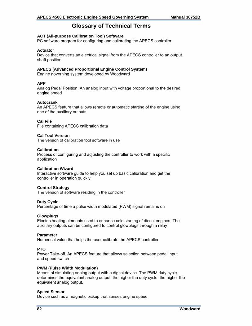
APECS 4500 Electronic Engine Speed Governing System Manual 36752B
82 Woodward
Glossary of Technical Terms ACT (All-purpose Calibration Tool) Software PC software program for configuring and calibrating the APECS controller Actuator Device that converts an electrical signal from the APECS controller to an output shaft position APECS (Advanced Proportional Engine Control System) Engine governing system developed by Woodward APP Analog Pedal Position. An analog input with voltage proportional to the desired engine speed Autocrank An APECS feature that allows remote or automatic starting of the engine using one of the auxiliary outputs Cal File File containing APECS calibration data Cal Tool Version The version of calibration tool software in use Calibration Process of configuring and adjusting the controller to work with a specific application Calibration Wizard Interactive software guide to help you set up basic calibration and get the controller in operation quickly Control Strategy The version of software residing in the controller Duty Cycle Percentage of time a pulse width modulated (PWM) signal remains on Glowplugs Electric heating elements used to enhance cold starting of diesel engines. The auxiliary outputs can be configured to control glowplugs through a relay Parameter Numerical value that helps the user calibrate the APECS controller PTO Power Take-off. An APECS feature that allows selection between pedal input and speed switch PWM (Pulse Width Modulation) Means of simulating analog output with a digital device. The PWM duty cycle determines the equivalent analog output: the higher the duty cycle, the higher the equivalent analog output. Speed Sensor Device such as a magnetic pickup that senses engine speed
Manual 36752B APECS 4500 Electronic Engine Speed Governing System
Woodward 83
Chapter 7. Service Options
Product Service Options If you are experiencing problems with the installation, or unsatisfactory performance of a Woodward product, the following options are available: Consult the troubleshooting guide in the manual. Contact the manufacturer or packager of your system. Contact the Woodward Full Service Distributor serving your area. Contact Woodward technical assistance (see “How to Contact Woodward”
later in this chapter) and discuss your problem. In many cases, your problem can be resolved over the phone. If not, you can select which course of action to pursue based on the available services listed in this chapter.
OEM and Packager Support: Many Woodward controls and control devices are installed into the equipment system and programmed by an Original Equipment Manufacturer (OEM) or Equipment Packager at their factory. In some cases, the programming is password-protected by the OEM or packager, and they are the best source for product service and support. Warranty service for Woodward products shipped with an equipment system should also be handled through the OEM or Packager. Please review your equipment system documentation for details. Woodward Business Partner Support: Woodward works with and supports a global network of independent business partners whose mission is to serve the users of Woodward controls, as described here:
A Full Service Distributor has the primary responsibility for sales, service, system integration solutions, technical desk support, and aftermarket marketing of standard Woodward products within a specific geographic area and market segment.
An Authorized Independent Service Facility (AISF) provides authorized service that includes repairs, repair parts, and warranty service on Woodward's behalf. Service (not new unit sales) is an AISF's primary mission.
A Recognized Engine Retrofitter (RER) is an independent company that does retrofits and upgrades on reciprocating gas engines and dual-fuel conversions, and can provide the full line of Woodward systems and components for the retrofits and overhauls, emission compliance upgrades, long term service contracts, emergency repairs, etc.
A Recognized Turbine Retrofitter (RTR) is an independent company that does both steam and gas turbine control retrofits and upgrades globally, and can provide the full line of Woodward systems and components for the retrofits and overhauls, long term service contracts, emergency repairs, etc.
A current list of Woodward Business Partners is available at www.woodward.com/support/directory.cfm.

APECS 4500 Electronic Engine Speed Governing System Manual 36752B
84 Woodward
Woodward Factory Servicing Options The following factory options for servicing Woodward products are available through your local Full-Service Distributor or the OEM or Packager of the equipment system, based on the standard Woodward Product and Service Warranty (5-01-1205) that is in effect at the time the product is originally shipped from Woodward or a service is performed: Replacement/Exchange (24-hour service) Flat Rate Repair Flat Rate Remanufacture Replacement/Exchange: Replacement/Exchange is a premium program designed for the user who is in need of immediate service. It allows you to request and receive a like-new replacement unit in minimum time (usually within 24 hours of the request), providing a suitable unit is available at the time of the request, thereby minimizing costly downtime. This is a flat-rate program and includes the full standard Woodward product warranty (Woodward Product and Service Warranty 5-01-1205). This option allows you to call your Full-Service Distributor in the event of an unexpected outage, or in advance of a scheduled outage, to request a replacement control unit. If the unit is available at the time of the call, it can usually be shipped out within 24 hours. You replace your field control unit with the like-new replacement and return the field unit to the Full-Service Distributor. Charges for the Replacement/Exchange service are based on a flat rate plus shipping expenses. You are invoiced the flat rate replacement/exchange charge plus a core charge at the time the replacement unit is shipped. If the core (field unit) is returned within 60 days, a credit for the core charge will be issued. Flat Rate Repair: Flat Rate Repair is available for the majority of standard products in the field. This program offers you repair service for your products with the advantage of knowing in advance what the cost will be. All repair work carries the standard Woodward service warranty (Woodward Product and Service Warranty 5-01-1205) on replaced parts and labor. Flat Rate Remanufacture: Flat Rate Remanufacture is very similar to the Flat Rate Repair option with the exception that the unit will be returned to you in “like-new” condition and carry with it the full standard Woodward product warranty (Woodward Product and Service Warranty 5-01-1205). This option is applicable to mechanical products only.
Returning Equipment for Repair If a control (or any part of an electronic control) is to be returned for repair, please contact your Full-Service Distributor in advance to obtain Return Authorization and shipping instructions. When shipping the item(s), attach a tag with the following information: return authorization number; name and location where the control is installed; name and phone number of contact person; complete Woodward part number(s) and serial number(s); description of the problem; instructions describing the desired type of repair.

Manual 36752B APECS 4500 Electronic Engine Speed Governing System
Woodward 85
Packing a Control Use the following materials when returning a complete control: protective caps on any connectors; antistatic protective bags on all electronic modules; packing materials that will not damage the surface of the unit; at least 100 mm (4 inches) of tightly packed, industry-approved packing
material; a packing carton with double walls; a strong tape around the outside of the carton for increased strength.
To prevent damage to electronic components caused by improper handling, read and observe the precautions in Woodward manual 82715, Guide for Handling and Protection of Electronic Controls, Printed Circuit Boards, and Modules.
Replacement Parts When ordering replacement parts for controls, include the following information: the part number(s) (XXXX-XXXX) that is on the enclosure nameplate; the unit serial number, which is also on the nameplate.
Engineering Services Woodward offers various Engineering Services for our products. For these services, you can contact us by telephone, by email, or through the Woodward website. Technical Support Product Training Field Service Technical Support is available from your equipment system supplier, your local Full-Service Distributor, or from many of Woodward’s worldwide locations, depending upon the product and application. This service can assist you with technical questions or problem solving during the normal business hours of the Woodward location you contact. Emergency assistance is also available during non-business hours by phoning Woodward and stating the urgency of your problem. Product Training is available as standard classes at many of our worldwide locations. We also offer customized classes, which can be tailored to your needs and can be held at one of our locations or at your site. This training, conducted by experienced personnel, will assure that you will be able to maintain system reliability and availability. Field Service engineering on-site support is available, depending on the product and location, from many of our worldwide locations or from one of our Full-Service Distributors. The field engineers are experienced both on Woodward products as well as on much of the non-Woodward equipment with which our products interface. For information on these services, please contact us via telephone, email us, or use our website: www.woodward.com/support.

APECS 4500 Electronic Engine Speed Governing System Manual 36752B
86 Woodward
How to Contact Woodward For assistance, call one of the following Woodward facilities to obtain the address and phone number of the facility nearest your location where you will be able to get information and service.
Electrical Power Systems Facility ---------------- Phone Number Brazil ------------- +55 (19) 3708 4800 China ----------- +86 (512) 6762 6727 Germany: Kempen ---- +49 (0) 21 52 14 51 Stuttgart ----- +49 (711) 78954-0 India --------------- +91 (129) 4097100 Japan -------------- +81 (43) 213-2191 Korea -------------- +82 (51) 636-7080 Poland --------------- +48 12 295 13 00 United States ---- +1 (970) 482-5811
Engine Systems Facility ---------------- Phone Number Brazil ------------- +55 (19) 3708 4800 China ----------- +86 (512) 6762 6727 Germany: Stuttgart ----- +49 (711) 78954-0 India --------------- +91 (129) 4097100 Japan -------------- +81 (43) 213-2191 Korea -------------- +82 (51) 636-7080 The Netherlands - +31 (23) 5661111 United States ---- +1 (970) 482-5811
Turbine Systems Facility ---------------- Phone Number Brazil ------------- +55 (19) 3708 4800 China ----------- +86 (512) 6762 6727 India --------------- +91 (129) 4097100 Japan -------------- +81 (43) 213-2191 Korea -------------- +82 (51) 636-7080 The Netherlands - +31 (23) 5661111 Poland --------------- +48 12 295 13 00 United States ---- +1 (970) 482-5811
You can also contact the Woodward Customer Service Department or consult our worldwide directory (www.woodward.com/support/directory.cfm) for the name of your nearest Woodward distributor or service facility.
Technical Assistance If you need to telephone for technical assistance, you will need to provide the following information. Please write it down here before phoning:
Your Name
Site Location
Phone Number
Fax Number
Engine/Turbine Model Number Manufacturer
Number of Cylinders (if applicable)
Type of Fuel (gas, gaseous, steam, etc)
Rating
Application
Control/Governor #1 Woodward Part Number & Rev. Letter
Control Description or Governor Type
Serial Number
Control/Governor #2 Woodward Part Number & Rev. Letter
Control Description or Governor Type
Serial Number
Control/Governor #3 Woodward Part Number & Rev. Letter
Control Description or Governor Type
Serial Number
If you have an electronic or programmable control, please have the adjustment setting positions or the menu settings written down and with you at the time of the call.


We appreciate your comments about the content of our publications.
Send comments to: [email protected]
Please reference publication 36752B.
PO Box 1519, Fort Collins CO 80522-1519, USA 1000 East Drake Road, Fort Collins CO 80525, USA Phone +1 (970) 482-5811 Fax +1 (970) 498-3058
Email and Website—www.woodward.com
Woodward has company-owned plants, subsidiaries, and branches, as well as authorized distributors and other authorized service and sales facilities throughout the world.
Complete address / phone / fax / email information for all locations is available on our website.
2010/11/Kraków