shodhganga.inflibnet.ac.inshodhganga.inflibnet.ac.in/bitstream/10603/75657/18/18_appendix a.pdf* #...
TRANSCRIPT

APPENDIX-A DESIGN OF A RIGID PAVEMENT FOR RURAL ROAD ANDNATIONAL HIGHWAY DEVELOPMENT
1i
APPENDIX-A[
DESIGN OF A RIGID PAVEMENTi
RURAL ROADi
ANDij
NATIONAL HIGHWAY!i
DEVELOPMENT
236

APPEND! X-A DESIGN OF A RIGID PAVEMENT FOR RURAL ROAD ANDNATIONAL HIGHWAY DEVELOPMENT
DESIGN OF A CEMENT CONCRETE PAVEMENT FOR RURAL ROAD
(IRC: SP: 20-2002 / IRC: SP: 62-2004)
A cement concrete pavement is to be designed for a Rural Road in Gujarat State
having a traffic volume of upto 500 vehicles per day consisting vehicles, like, agricultural
tractors/trailers, light goods vehicles, heavy trucks, buses, animal drawn vehicles,
motorized two-wheels and cycles. The soil has a soaked CBR value of 2%, 4% and 6% for
30kN wheel load.
Table AA-1
Design of CC Pavement for Rural Roads
Design Parameters: Sample D1 (6% CBR-30kN Wheel Load)
Traffic Volume (A) - UP TO 500 cvpd (Assume)
Concrete Grade (fc) = 25 N/mm2
Characteristic Compressive Cube Strength = 40.33 N/mm2 at 28 Days Actual
Compressive Strength
Flexural Strength ( ff) = 5.00 N/mm2 [50.00 kg/cm2]
90 days Flexural strength = 6.10 N/mm2 [61.00 kg/cm2] .
Soaked CBR Value (%) = 0.06(6%)
Modulus of Subgrade Reaction (k) = 45 (N/mm2/mm)*10'3
Effective K Value (20% more) = 54 (N/mm2/mm)* 10"3
Elastic modulus of Concrete (Ec) (As per Actual
Calculation)= 28,417 N/mm2
Poisson’s ratio (p) = 0.15
Coefficient of thermal coefficient of concrete (a) = 0.00001/°C
Design Wheel Load (P) = 30 kN
Tyre pressure (q) = 0.5 N/mm2 [5 kg/cm2]
Spacing of Contraction Joints (L) = 3.75m [3750 mm]
Width of Slab (W) = 3.75m [3750 mm]
Radius of load contact (assumed circular), (a) =13.82 cm
Trial Thickness for Slab, h = 150mm.
237

APPENDIX-A DESIGN OF A RIGID PAVEMENT FOR RURAL ROAD ANDNATIONAL HIGHWAY DEVELOPMENT
[ ' ■
Check for Temperature Stresses: j
Assuming a contraction joint spacing of 3.75 m and 3.75m width
1. Temperature Stress (ote): !
The temperature differential (At) for Gujarat for a slab thickness of 150mm is 12.5°C.
The Radius of Relative Stiffness, 1 = *1 h .’ AJ 12 (1- n
Hence, 1 = 623.79mm. !
L/l = 3750 / 623.79= 6.0 ji
W/l = 3750 / 623.79= 6.0 Ij
Both values are same, if not then adopt greater one.
Bradbury’s Coefficient, C = 0.942 (from figure 1, pg. 9)
[Value of C can be ascertained directly from Bradbury’s chart against values of L/l and W/l] j
Temperature Stress in edge region, ote = Ea^At- c
Hence, ote = 1.63 N/mmI 2. |
|2. Edge Load Stress (ole):
From Page: 12, Edge Load Stress, ■
Radius of equivalent distribution of pressure (bj,
b = a(if(a/h>= 1.724);
(b) = Vl.6 a2 + h2 - 0.675 h if (a/h < 1.724),
For slab thickness of 150mm; Edge Load Stress, ole, is 3.39 N/mm2 (3.39 MPa).j
Total Stress = Edge Load Stress + Temperature j Stress = 3.39 + 1.63 = 5.02 N/mm2, whichI n
is less than the allowable flexural strength of 6.10 N/mm .
Hence, assumed thickness of slab = 150mm, is OK. [As per Temperature Stress Criteria]
I1
238

APPENDIX-A DESIGN OF A RIGID PAVEMENT FOR RURAL ROAD ANDNATIONAL HIGHWAY DEVELOPMENT
Check for Corner Stresses (alc):
From Fig. 5 (Page 12), Comer Load Stress for wheel load of 30kN, for k = 54.0 (N/mm2/mm)*10'3 = 0.054 N/mm2/mm = 0.054 N/mm2/mm (Approx.) and
slab thickness of 150mm is 3.20 N/mm2 (3.20 MPa).
[Temperature Stress in the corner region is negligible, as the comers are relatively free to
warp, hence it can be ignored.]
Hence, <rlc = 3.20 N/mm2, which is less than the allowable flexural strength of 6.10
N/mm2.
So, the slab thickness of 150mm is Safe.
The calculations presented above are sample calculations. Similar calculations are done
using various values of flexural strengths of concrete.
239

APPENDIX-A DESIGN OF A RIGID PAVEMENT FOR RURAL ROAD ANDNATIONAL HIGHWAY DEVELOPMENT
DESIGN OF A CEMENT CONCRETE PAVEMENT FOR RURAL ROAD
(IRC: SP: 20-2002 / IRC: SP: 62-2004)
A cement concrete pavement is to be designed for a Rural Road in Gujarat State
having a traffic volume of upto 500 vehicles per day consisting vehicles, like, agricultural
tractors/trailers, light goods vehicles, heavy trucks, buses, animal drawn vehicles,
motorized two-wheels and cycles. The soil has a soaked CBR value of 2%, 4% and 6% for
5 lkN wheel load.
Table AB-1
Design of CC Pavement for Rural Roads
Design Parameters: Sample D1 (6% CBR-51kN Wheel Load)
Traffic Volume (A) = UP TO 500 cvpd (Assume)
Concrete Grade (fc) = 25 N/mm2
Characteristic Compressive Cube Strength j = 40.33 N/mm2 at 28 Days Actual
Compressive Strength
Flexural Strength (ff) = 5.00 N/mm2 [50.00 kg/cm2]
90 days Flexural strength = 6.10 N/mm2 [61.00 kg/cm2]
Soaked CBR Value (%) = 0.06 (6%)
Modulus of Subgrade Reaction (k) = 45 (N/mm2/mm)*10'J
Effective K Value (20% more) = 54 (N/mm2/mm)* 10‘a
Elastic modulus of Concrete (Ec) (As per Actual
Calculation)= 28,417 N/mm2
Poisson’s ratio (p) = 0.15
Coefficient of thermal coefficient of concrete (a) = 0.00001/°C
Design Wheel Load (P) = 51 kN
Tyre pressure (q) = 0.7 N/mm2 [7 kg/cm2]
Spacing of Contraction Joints (L) = 3.75m [3750 mm]
Width of Slab (W) = 3.75m [3750 mm]
Radius of load contact (assumed circular), (a) ; =15.23 cm
Trial Thickness for Slab, h = 150mm.
240

APPENDIX-A DESIGN OF A RIGID PAVEMENT FOR RURAL ROAD ANDNATIONAL HIGHWAY DEVELOPMENT
Check for Temperature Stresses:
Assuming a contraction joint spacing of 3.75 m and 3.75m width
3. Temperature Stress (ote): i| - '
The temperature differential (At) for Gujarat jfor a slab thickness of 150mm is 12.5°C.
The Radius of Relative Stiffness, 1= 4i 12 (l-)iz) k
Hence, 1 = 623.79mm. ;
L/l = 3750 / 623.79= 6.0 |
W/l = 3750 / 623.79= 6.0 !
Both values are same, if not then adopt greater one.|
Bradbury’s Coefficient, C = 0.920 (from figure |1, pg. 9)
[Value of C can be ascertained directly from Bradbury’s chart against values of L/l and W/l] |
Temperature Stress in edge region, ate = C
jHence, ote= 1.63 N/ram2.
4. Edge Load Stress (ole):
From Page: 12, Edge Load Stress, |
Radius of equivalent distribution of pressure (b),
b = a(if(a/h>= 1.724); j(b) = Vl.6 a2 + h2 - 0.675 h if (a/h < 1.724), J
|For slab thickness of 150mm; Edge Load Stress, ole, is 3.39 N/mm2 (3.39 MPa).
I
jTotal Stress = Edge Load Stress + Temperature)Stress = 3.39 + 1.63 = 5.02 N/mm2, which
is less than the allowable flexural strength of 6.10 N/mm .
Hence, assumed thickness of slab = 150mm. [As per Temperature Stress Criteria]
241

APPENDIX-A DESIGN OF A RIGID PAVEMENT FOR RURAL ROAD AND
Check for Corner Stresses (olc):
From Fig. 5 (Page 12), Comer Load Stress for wheel load of 30kN, for k = 54.0 (N/mm2/mm)*10'3 = 0.054 N/mm2/mm = 0.054 N/mm2/mm (Approx.) and
slab thickness of 190mm is 3.20 N/mm2 (3.20 MPa).
[Temperature Stress in the comer region is negligible, as the comers are relatively free to
warp, hence it can be ignored.] j
Hence, oIc = 3.20 N/mm2, which is less than the allowable flexural strength of 6.10
N/mm2.
iSo, the slab thickness of 150mm is Safe.
The calculations presented above are sample calculations. Similar calculations are done
using various values of flexural strengths of concrete.
242

APPENDIX-A DESIGN OF A RIGID PAVEMENT FOR RURAL ROAD ANDNATIONAL HIGHWAY DEVELOPMENT
DESIGN OF A NATIONAL HIGHWAY ROAD PAVEMENT (IRC: 58-2002)
A cement concrete pavement is to be designed for a two- lane two-way National Highway
in Gujarat State. The total two-way traffic is 3000 commercial vehicles per day (evpd) at
the end of the construction period. Design parameters are provided in Table AC-1 and the
traffic axle load spectrum is given Table AC-2.
TABLE AC-1
Design of CC Pavement for Two- Lane Two-Way National Highway
Design parameters: Sample G5 (6% CBR-100DLC-3000CVPD)
Present Traffic =3000 cvpd
Design life =20 yrs.
Compressive Strength (fck) = 56.63 N/mm2 = 566.3 kg/cm2
Flexural strength of cement concrete
(Modulus of rupture)
= 8.15 N/mm2 = 81.50 kg/cm2
CBR = 6%
Dry Lean Concrete (DLC) =100 mm
Effective modulus of subgrade reaction of the DLC
sub-base (k)
= 18.7 kg/cm3
Elastic modulus of concrete (E) = 40417 N/mm2
Poisson’s ratio (p) = 0.15
Coefficient of thermal coefficient of concrete (a) = 10 x 10‘6/°C
Tyre pressure (q) = 8 kg/cm2
Rate of traffic increase (r) = 0.075
Spacing of contraction joints (L) = 4.5m
Width of slab (b) = 3.5m
Load safety factor (LSF) = 1.2
Wheel load (P) = 8000 kg
C/C distance between two tyres (S) = 31 cm
Joint width (z) = 2.0 cm
243

APPENDIX-A DESIGN OF A RIGID PAVEMENT FOR RURAL ROAD ANDNATIONAL HIGHWAY DEVELOPMENT
The axle load spectrum obtained from axle load survey is given in the following:
Table AC-2
Axle Load Spectrum Obtained From Axle Load Survey
Single Axle Loads Tandem Axle Loads
Axle load class, Percentage of axle Axle load class, Percentage of axle
tons loads tons loads
19-21 0.6 34-38 0.3
17-19 1.5 30-34 0.3
15-17 4.8 26-30 0.6
13-15 10.8 22-26 1.8
11-13 22.0 18-22 1.5
9-11 23.3 14-18 0.5
Less than 9 30.0 Less than 14 2.0
Total 93.0 Total 7.0
365 X { (1 + r)2 — 1}Cumulative repetition in 20 yrs. = r
= 47,418,626 commercial vehicles
Design traffic = 25 per cent of the total repetitions of commercial vehicles = 11,854,657
Front axles of the commercial vehicles carry much lower loads and cause small flexural
stress in the concrete pavements and they need not be considered in the pavement design.
Only the rear axles, both single and tandem, should be considered for the design. In the
example, the total number of real axles is, therefore, 11,854,657. Assuming that the
midpoint of the axle load class represents the group, the total repetitions of the single axle
and tandem axle loads are as follows:
244

APPENDIX-A DESIGN OF A RIGID PAVEMENT FOR RURAL ROAD ANDNATIONAL HIGHWAY DEVELOPMENT
Table AC-3
Total Repetitions of the Single Axle and Tandem Axle Loads
Single Axle Tandem AxleLoad in tonnes Expected
repetitionsLoad in tonnes Expected
repetitions20 71127 36 3556418 177820 i 32 3556416 569023 : 28 7112814 1280303 24 21338412 2608024 1 20 17782010 27622135 16 59273
Less than 10 3556397 Less than 16 237093
Trial Thickness = 19 cmTable AC-4
Cumulative Fatigue Life
Axle load (AL), tonnes
AL x 1.2
Stress, kg/cm2
from charts
Stressratio
Expected Repetitions, n
Fatigue life, N
Fatigue life consumed
(1) (2) (3) (4) (5) (6) Ratio (5)/(6)
Single axle20 24.0 44.80 0.55 71128 12.38 x 10⁴ 0.5718 21.6 41.00 0.50 177820 64.30 x 10⁴ 0.2816 19.2 37.40 0.46 569024 15.48 x 10⁶ 0.0414 16.8 35.63 0.44 1280303 47.22 x 10* 0.00
Tandem axle36 43.2 31.68 0.39 35564 Infinity 0.00
Cumulative fatigue life consumed 0.89
The cumulative fatigue life consumed being less than 1; the design is safe from fatigue
considerations.
Check for Temperature Stresses:Eat
Edge warping stress (Ste) = 2
Radius of relative stiffness (/) = 59.62 cm
245

APPENDIX-A DESIGN OF A RIGID PAVEMENT FOR RURAL ROAD ANDNATIONAL HIGHWAY DEVELOPMENT
(see below under comer stress)
Therefore, L// = 450 / 59.62 = 7.5
Bradbury’s Coefficient, which can be ascertained directly from Bradbury’s chart against
values of U l and B/1, (C) = 1.054 from fig.2. (IRC: 58-2002)
The temperature differential was taken as 12.98°C for the Gujarat region.
Eat „■ ...... ^ i ry
Edge warping stress = 2 =27.65 kg/cm
Total of temperature warping stress and the highest axle load stress = 44.835 + 27.65 = 72.48 kg/cm2 which is less than 81.50 kg/cm2, the flexural strength. So the pavement
thickness of 19 cm is safe under the combined action of wheel load and temperature.
Check for Corner Stresses:
Comer stress is not critical in a dowelled pavement. The comer stress can be calculated
value from the following formula: '
Comer stress Sc = - j |l — (^) j
The 98 percentile axle load is 16 tonnes. The wheel load, therefore, is 8 tonnes.
Radius of relative stiffness (/) = 4 Eh312(1 -ii2)k 59.62 cm
a = radius of area of contact of wheel.
iConsidering a single axle dual wheel,
a=(-)1/2
V pn /i
a = 0.8521 x —-—h -(—l—)0'5 a = 26.52 cmq X n n\ 0.5227 xq )
Comer stress S0= ^ |l — (~j~) j =28.38 kg/cm2
The comer stress is less than the flexural strength of the concrete, i.e., 81.50 kg/cm2 and
the pavement thickness of 19 cm assumed is safe.
246

APPENDIX-A DESIGN OF A RIGID PAVEMENT FOR RURAL ROAD ANDNATIONAL HIGHWAY DEVELOPMENT
Design of Dowel Bars
Table AC-5
Design Parameters for Dowel Bars
Diameter of the dowel bar (b) = 3.2 cm (assumed)
Modulus of Dowel/Concrete interaction (Dowel support) (K) = 41500 kg/cm2/cm
Modulus of the elasticity of the Dowel, kg/cm2
Dowel/Concrete interaction (E)
= 2.0 X 10⁶ kg/cm2
Moment of Inertia of Dowel (I) = 5.147 cm4
Design wheel load (P) = 98 percentile axle load is 16 tonne. The wheel load, therefore, is
8000 kg (dual wheel load)
Percentage of load transfer = 40 %
Permissible bearing stress in concrete is calculated as under:
„ _ (l0.16-6)/cfcFb—:
fCk = characteristic compressive strength of concrete cube (15 cm) after 28 days curing
concrete= 566.30kg/cm2
Fb;(10.16—2.5) 566.30
9.525: 455.42 kg/cm~
Assumed spacing between the dowel bars = 19 cm
First dowel bar is placed at a distance = 15 cm from the pavement edge
Assumed length of the dowel bar = 50 cm
Dowel bars upto a distance of 1.0 x radius of relative stiffness, from the point of load
application are effective in load transfer.
Number of dowel bars participating in load transfer when wheel load is just over the dowel
bar close to the edge of the slab =1+1/ spacing = 1+ 59.62 / 19 = 4 dowels.
247

APPENBIX-A DESIGN OF A RIGID PAVEMENT FOR RURAL ROAD ANDNATIONAL HIGHWAY DEVELOPMENT
»a—b———iL-i.i-'.——TTwm~~—nmmr—MrifffMiM—■——w—
Assuming that the load transferred by the first dowel is Pt and assuming that the load on
dowel bar at a distance of 1 from the first dowel to be zero, the total transferred by dowel
bar system
= (1+^ + ^+L^)Pt= 2.09Pt
Load carried by the outer dowel bar, P, = 'MS*‘ 1“J m
=1532.55 kg
Check for Bearing Stress:
7Tb*Moment of Inertia of Dowel, I = —’ 64
T_ 7TX2.54 _ , n„___ 41------ ---------1.92 cm64
Relative stiffness of dowel bar embedded in concrete (P) =4 /~Kb~ y 4 El
Where;
P41500 X 2.5 0.29-y4X2X 10s X 1.92
Bearing stress in dowel bar = (Pt X k) X (2+Pz) / (4p3EI)
= 452.50 kg/cm2 which is less than 455.42 kg/cm2
Hence, the dowel bar spacing and diameter assumed are safe.
Design of Tie Bars:
Table AC-6
Design Parameters for Tie Bars
Slab thickness (h) = 19 cm
Lane width (b) = 3.5 m
Coefficient of friction (f) = 1.5
Density of concrete (W) = 2400 kg/m'3
Allowable tensile stress in plain bars (S), (As per IRC: 21-2000) = 1250 kg/m2
248

APPENDIX-A DESIGN OF A RIGID PAVEMENT FOR RURAL ROAD ANDNATIONAL HIGHWAY DEVELOPMENT
Allowable tensile stress in deformed bars (S), (As per IRC; 21-2000) = 2000 kg/m2
Allowable bond stress in plain tie bars (B) = 17.5 kg/m2
Allowable bond stress in deformed tie bars (B) = 24.6 kg/m2
Diameter of tie bar (d) = 12 mm
1. Spacing and length of the plain bar
Area of steel bar per metre width of joint to resist the frictional force at slab bottom
As = ~ = 1.92 cm2
Assuming a diameter of tie bar of 12 mm, the cross sectional area7t d2
Cross sectional area of tie bar (A) = -—4
A=1.13 sq.cm.
Perimeter of tie bar (P) = n d = jc x 1.2 = 3.77 cm
Spacing of tie bars = A / As =59.02 cm
Provide at a spacing of 59 cm c/c
Length of tie bar (L) =
Cross sectional area of tie bar (A) = 1.13 sq.cm.
Perimeter of Tie Bar (P) = 3.77 cm
Length of tie bar (L) = = 42.86 cmBXP
Increase length by 10 cm for loss of bond due to painting and another 5 cm for tolerance in
placement. Therefore, the length is
42.86 + 10 + 5 = 57.86 cm, Say 58 cm
2. Spacing and length of the deformed bar
Area of steel bar per metre width of joint to resist the frictional force at slab bottom. bfW . 2As = —= 1.20 cm
Assuming a diameter of tie bar of 12 mm, the cross sectional area
Cross sectional area of tie bar (A) =
A=1.13 sq.cm.
Perimeter of Tie Bar (P) = rc d = tc x 1.2 = 3.77 cm
Spacing of tie bars = A / As =94.44 cm
249

APPENDIX-A DESIGN OF A RIGID PAVEMENT FOR RURAL ROAD ANDNATIONAL HIGHWAY DEVELOPMENT
Provide at a spacing of 94 cm c/c
Length of tie bar (L) = j
Cross sectional area of tie bar (A) =1.13 sq.cml
Perimeter of Tie Bar (P) = 3.77 cm
Length of tie bar (L) = = 48.78 cmB X P
Increase length by 10 cm for loss of bond due to painting and another 5 cm for tolerance in
placement. Therefore, the length is 48.78 + 10 + 5 = 63.78 cm, Say 64 cm
250

APPENDIX-A DESIGN OF A RIGID PAVEMENT FOR RURAL ROAD ANDNATIONAL HIGHWAY DEVELOPMENT
DESIGN OF A NATIONAL HIGHWAY ROAD PAVEMENT (IRC: 58-2002)
A cement concrete pavement is designed for a two- lane two-way National Highway in
Gujarat State. The total two-way traffic is 3000 commercial vehicles per day (cvpd) at the
end of the construction period. Design parameters are provided in Table AD-1 and traffic
axle load spectrum is given Table AD-2.
Table AD-1
Design of CC Pavement for Two- Lane Two-Way National Highway
Design parameters: Sample G5 (6% CBR-150DLC-3000CVPD)
Present Traffic =3000 cvpd
Design life =20 yrs.
Compressive Strength (fck) = 56.63N/mm2 = 566.3 kg/cm2
Flexural strength of cement concrete
(Modulus of rupture)
= 8.15 N/mm2 = 81.5 kg/cm2
CBR = 6%
Dry Lean Concrete (DLC) =150 mm
Effective modulus of subgrade reaction of the DLC
sub-base (k)
= 24.25 kg/cm3
Elastic modulus of concrete (E) = 40417 kg/cm2
Poisson’s ratio (p) = 0.15
Coefficient of thermal coefficient of concrete (a) = 10 x 10'b/'C
Tyre pressure (q) = 8 kg/cm2
Rate of traffic increase (r) = 0.075
Spacing of contraction joints (L) = 4.5m
Width of slab (b) = 3.5m
Load safety factor (LSF) = 1.2
Wheel load (P) = 8000 kg
C/C distance between two tyres (S) = 31 cm
Joint width (z) ! = 2.0 cm
251

APPENDIX-A DESIGN OF A RIGID PAVEMENT FOR RURAL ROAD ANDNATIONAL HIGHWAY DEVELOPMENT
The axle load spectrum obtained from axle load survey is given in the following:
Table AD-2
Axle Load Spectrum Obtained From Axle Load Survey
Single Axle Loads Tandem Axle Loads
Axle load class, Percentage of axle Axle load class, Percentage of axle
tons loads tons loads
19-21 0.6 34-38 0.3
17-19 1.5 30-34 0.3
15-17 4.8 26-30 .0.6
13-15 10.8 22-26 1.8
11-13 22.0 18-22 1.5
9-11 23.3 14-18 0.5
Less than 9 30.0 Less than 14 2.0
Total 93.0 Total 7.0
365 Xi4 { (1 + r)2 — 1}Cumulative repetition in 20 yrs. = r
= 47,418,626 commercial vehicles
Design traffic = 25 per cent of the total repetitions of commercial vehicles = 11,854,657
Front axles of the commercial vehicles carry much lower loads and cause small flexural
stress in the concrete pavements and they need not he considered in the pavement design.
Only the rear axles, both single and tandem, should be considered for the design. In the
example, the total number of real axles is, therefore, 11,854,657. Assuming that mid-point
of the axle load class represents the group, the total repetitions of the single axle and
tandem axle loads are as follows:
252

APPENDIX-A DESIGN OF A RIGID PAVEMENT FOR RURAL ROAD AND '_______________________ NATIONAL HIGHWAY DEVELOPMENT
Table AD-3
Total Repetitions of the Single Axle and Tandem Axle Loads
Single Axle Tandem Axle
Load in tonnes Expected
repetitions
Load in tonnes Expected
repetitions
20 71127 36 35564
18 177820 32 35564
16 569023 28 71128
14 1280303 24 213384
12 2608024 . 20 177820
10 27622135 16 59273
Less than 10 3556397 Less than 16 237093
Trial Thickness = 19 cm
Table AD-4
Cumulative Fatigue Life
Axle load
(AL),
tonnes
AL x
1.2
Stress,kg/cm2
from charts
Stress
ratio
Expected
Repetitions, n
Fatigue
life, N
Fatigue life
consumed
(1) (2) (3) (4) (5) (6) Ratio
(5)/(6)
Single axle
20 24.0 42.30 0.52 71128 35.00 x 10b 0.21
18 21.6 39.00 0.48 177820 26.43 x 10s 0.07
16 19.2 35.50 0.44 569024 22.68 x 10y 0.00
14 16.8 33.80 0.41 1280303 Infinity 0.00
Tandem axle
36 43.2 30.24 0.37 ; 35564 Infinity 0.00
Cumulative fatigue liiFe consumed 0.28
253

APPENDIX-A DESIGN OF A RIGID PAVEMENT FOR RURAL ROAD ANDNATIONAL HIGHWAY DEVELOPMENT
ifcl iiihiliaMaWiMWHW—I—————
The cumulative fatigue life consumed being less than 1; the design is safe from fatigue
considerations.
Check for Temperature Stresses:
EatEdge warping stress (Ste) = 2 L
Radius of relative stiffness (/) = 55.87 cm
(see below under comer stress)
Therefore, U l = 450 / 55.87 = 8.1
Bradbury’s Coefficient, which can be ascertained directly from Bradbury’s chart against
values of L/1 and B/1, (C) = 1.077 from fig.2. (IRC: 58-2002)
The temperature differential was taken as 12.98°C for the Gujarat region.
Eat _Edge warping stress = 2 = 28.25 kg/cm
Total of temperature warping stress and the highest axle load stress = 42.33 + 28.25 = 70.59 kg/cm2 which is less than 81.50 kg/cm2, the flexural strength. So the pavement
thickness of 19 cm is safe under the combined action of wheel load and temperature.
Check for Corner Stresses:
Comer stress is not critical in a dowelled pavement. The comer stress can be calculated
value from the following formula:
Comer stress Sc = |l 1 — (^r) ]
The 98 percentile axle load is 16 tonnes. The wheel load, therefore, is 8 tonnes.
I pf.3
Radius of relative stiffness (l) = 4 I———= 55.87 cm
a = radius of area of contact of wheel.
Considering a single axle dual wheel,
254

APPENDIX-A DESIGN OF A RIGID PAVEMENT FOR RURAL ROAD ANDNATIONAL HIGHWAY DEVELOPMENT
a = 0.8521 x ——Iqxn
S / P n V 0.5227 xq
a = 26.52 cm '
Comer stress Sc= ^ j = 25.29 kg/cm2
The comer stress is less than the flexural strength of the concrete, i.e., 81.50 kg/cm2 and
the pavement thickness of 19 cm assumed is safe.
Design of Dowel Bars
Table AD-5
Design Parameters for Dowel Bars
Diameter of the dowel bar (b) = 3.2 cm (assumed)
Modulus of Dowel/Concrete interaction (Dowel support) (K) = 41500 kg/cm2/cm
Modulus of the elasticity of the Dowel, kg/cm2
Dowel/Concrete interaction (E)i
= 2.0 x 10⁶ kg/cm2
Moment of Inertia of Dowel (I) = 5.147 cm4
Design wheel load (P) = 98 percentile axle load is 16 tonne. The wheel load, therefore, is
8000 kg (dual wheel load)
Percentage of load transfer = 40 %i
Permissible bearing stress in concrete is calculated as under:i
(10.16-b)fckb 9.525 i
f0k = characteristic compressive strength of concrete cube (15 cm) after 28 days curing
concrete jI
= 566.3 kg/cm2
Fb = (10'16~g225) 56-6~ = 413.80kg/cm2 |
Assumed spacing between the dowel bars = 23.5 cm
First dowel bar is placed at a distance = 15 cm from the pavement edge
255
APPENDIX-A DESIGN OF A RIGID PAVEMENT FOR RURAL ROAD ANDNATIONAL HIGHWAY DEVELOPMENT
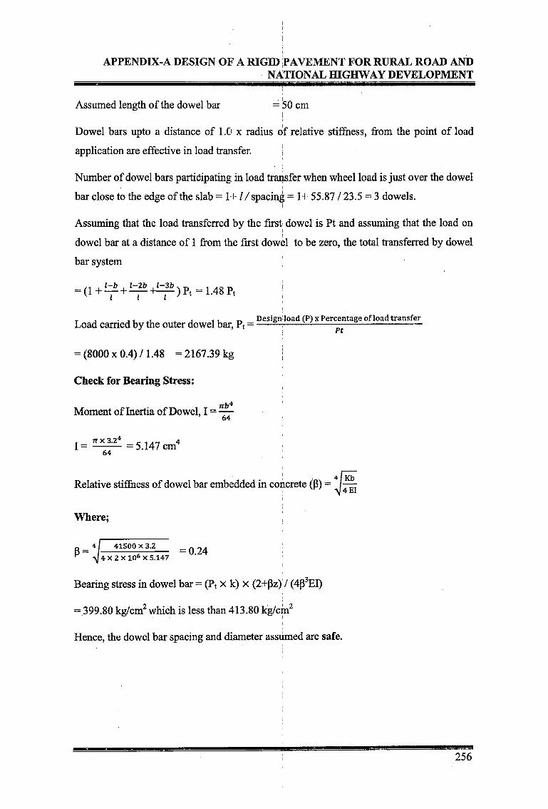
Assumed length of the dowel bar = 50 cm
Dowel bars upto a distance of 1.0 x radius of relative stiffness, from the point of load
application are effective in load transfer.
Number of dowel bars participating in load transfer when wheel load is just over the dowel
bar close to the edge of the slab =1+1/spacing = 1+ 55.87 / 23.5 = 3 dowels.I
Assuming that the load transferred by the first dowel is Pt and assuming that the load on
dowel bar at a distance of 1 from the first dowel to be zero, the total transferred by dowel
bar system [
= (1+^ + i=r+L7^)Pt = 1.48Pt ;
T , . ., x , .. Design load (P)x Percentage of load transferLoad earned by the outer dowel bar, Pt =------- ;---------------—----- ;-----------------
= (8000x0.4)/1.48 =2167.39 kg jCheck for Bearing Stress:
Ttb^Moment of Inertia of Dowel, I = —
T JT X 3.2* c-i.n 4I =-------- = 5.147 cm
64
Relative stiffness of dowel bar embedded in concrete (P):
Where:
P =41500 X 3.2 = 0.244 X 2 X 10s X 5.147
I
Bearing stress in dowel bar = (Pt x k) x (2+pz)'/ (4p3EI)
= 399.80 kg/cm2 which is less than 413.80 kg/cm2
Hence, the dowel bar spacing and diameter assumed are safe.
256

APPENDIX-A DESIGN OF A RIGID PAVEMENT FOR RURAL ROAD ANDNATIONAL HIGHWAY DEVELOPMENT
Design of Tie Bars:
Table AD-6
Design Parameters for Tie Bars
Slab thickness (h)i
= 19 cm
Lane width (b) = 3.5 m
Coefficient of friction (f) = 1.5
Density of concrete (W) ; = 2400 kg/mJ
Allowable tensile stress in plain bars (S), (As per IRC: 21-2000) = 1250 kg/m2
Allowable tensile stress in deformed bars (S), (As per IRC: 21-2000) = 2000 kg/m2
Allowable bond stress in plain tie bars (B) = 17.5 kg/m2
Allowable bond stress in deformed tie bars (B) = 24.6 kg/m2
Diameter of tie bar (d) = 12 mm
1. Spacing and length of the plain bar
Area of steel bar per metre width of joint to resist the frictional force at slab bottom
As = -y = 1.92 cm
Assuming a diameter of tie bar of 12 mm, the cross sectional arean dz i
Cross sectional area of tie bar (A) =
A=1.13 sq.cm.
Perimeter of tie bar (P) = n d = rc x 1.2 = 3.77 cm
Spacing of tie bars = A / As =59.02 cm
Provide at a spacing of 59 cm c/c
Length of tie bar (L) = ~~~~ jJti a r
Cross sectional area of tie bar (A) = 1.13 sq.cm.
Perimeter of Tie Bar (P) = 3.77 cm j
Length of tie bar (L) = = 42.86 cmJ3 b i
Increase length by 10 cm for loss of bond due to painting and another 5 cm for tolerance in
placement. Therefore, the length is 42.86 + 10 + 5 = 57.86 cm, Say 58 cm
257

APPENDIX-A DESIGN OF A RIGID PAVEMENT FOR RURAL ROAD ANDNATIONAL HIGHWAY DEVELOPMENT
2. Spacing and length of the deformed bar
Area of steel bar per metre width of joint to resist the frictional force at slab bottom. bfW . ... 2As = -^- = 1.20 cm i
Assuming a diameter of tie bar of 12 mm, the cross sectional area
Cross sectional area of tie bar (A) =
A=1.13 sq.cm.
Perimeter of Tie Bar (P) = it d = n x 1.2 = 3.77 cm
Spacing of tie bars = A / As =94.44 cm
Provide at a spacing of 94 cm c/c
Length of tie bar (L) = 2*^p-
Cross sectional area of tie bar (A) =1.13 sq.cm.
Perimeter of Tie Bar (P) = 3.77 cm
Length of tie bar (L) = ^^^ = 48.78 cmB X P
Increase length by 10 cm for loss of bond due to painting and another 5 cm for tolerance in
placement. Therefore, the length is 48.78 + 10 + 5 = 63.78 cm, Say 64 cm
258