aparamenta de interior m.t. 1 - iberapa.esiberapa.es/catalogos/productos/i_17_06_a.pdf ·...
TRANSCRIPT
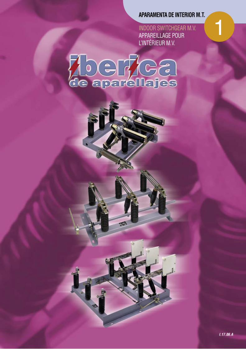
1APARAMENTA DE INTERIOR M.T.
I.17.06.A
INDOOR SWITCHGEAR M.V.APPAREILLAGE POUR L’INTÉRIEUR M.V.

PararrayosParafoudres / Arresters
Interruptores SF6 Interrupteurs SF6 / SF6 Switches
Celdas Cellules / Ring main units
Fusibles Fusibles / Fuses
Seccionadores Sectionneurs / Disconnectors

I-17-06.A IBERICA DE APARELLAJES www.iberapa.es Pág. 1 I-17-06.A IBERICA DE APARELLAJES www:iberapa.es Pág. 3
INDICE Pág.__________________________________________________________________________________________
1.- Características generales Caracteristiques generales General data............................................................................................................................................. 4
2.- Aisladores Isolateurs Insulators................................................................................................................................................. 6
3.- Pasamuros Passemurs entrées de poste Feed thoroughs (busing)
REF. IA -30, IA 36, …............................................................................................................................. 8
4.- Seccionadores Sectioneurs Disconnectors REF. IA –25, IA- 79, IA-27, IA-29,IA-340 ................................……………………………………………... 10
5.- Interruptor Interrupteur Switch REF. IA-200 SC/F/FR................................................................................................................................ 12
6.- Interruptor Interrupteur Switch REF. RI – RIF........................................................................................................................................... 16
7.- Mandos Commandes Operating mechanisme..........................................................................................................................… 25
9.- Relé RTE Relai RTE Relay RTE............................................................................................................................................... 30
NOTA IMPORTANTE:
Debido a las mejoras tecnológicas, las datos referenciados en el presente catálogo son susceptibles de variaciones, derecho que se reserva Ibérica de Aparellajes.
NOTE IMPORTANTE:
Etant doneé les ameliorations techniques, les valeurs auxquelles le present cataloque se réferè, sont sujettes à des variations dont Ibèrica se réserve le droit.
IMPORTANT NOTE:
Due to technological improvements, the data in this catalogue may be altered, Ibérica de Aparellajes reserving this right.
2
4
6
8
10
14
19
28
IA-27, IA-29
I-17-06.A IBERICA DE APARELLAJES www:iberapa.es Pág. 3
INDICE Pág.__________________________________________________________________________________________
1.- Características generales Caracteristiques generales General data............................................................................................................................................. 4
2.- Aisladores Isolateurs Insulators................................................................................................................................................. 6
3.- Pasamuros Passemurs entrées de poste Feed thoroughs (busing)
REF. IA -30, IA 36, …............................................................................................................................. 8
4.- Seccionadores Sectioneurs Disconnectors REF. IA –25, IA- 79, IA-27, IA-29,IA-340 ................................……………………………………………... 10
5.- Interruptor Interrupteur Switch REF. IA-200 SC/F/FR................................................................................................................................ 12
6.- Interruptor Interrupteur Switch REF. RI – RIF........................................................................................................................................... 16
7.- Mandos Commandes Operating mechanisme..........................................................................................................................… 25
9.- Relé RTE Relai RTE Relay RTE............................................................................................................................................... 30
NOTA IMPORTANTE:
Debido a las mejoras tecnológicas, las datos referenciados en el presente catálogo son susceptibles de variaciones, derecho que se reserva Ibérica de Aparellajes.
NOTE IMPORTANTE:
Etant doneé les ameliorations techniques, les valeurs auxquelles le present cataloque se réferè, sont sujettes à des variations dont Ibèrica se réserve le droit.
IMPORTANT NOTE:
Due to technological improvements, the data in this catalogue may be altered, Ibérica de Aparellajes reserving this right.
I-17-06.A IBERICA DE APARELLAJES www.iberapa.es Pág. 2 I-17-06.A IBERICA DE APARELLAJES www:iberapa.es Pág. 4
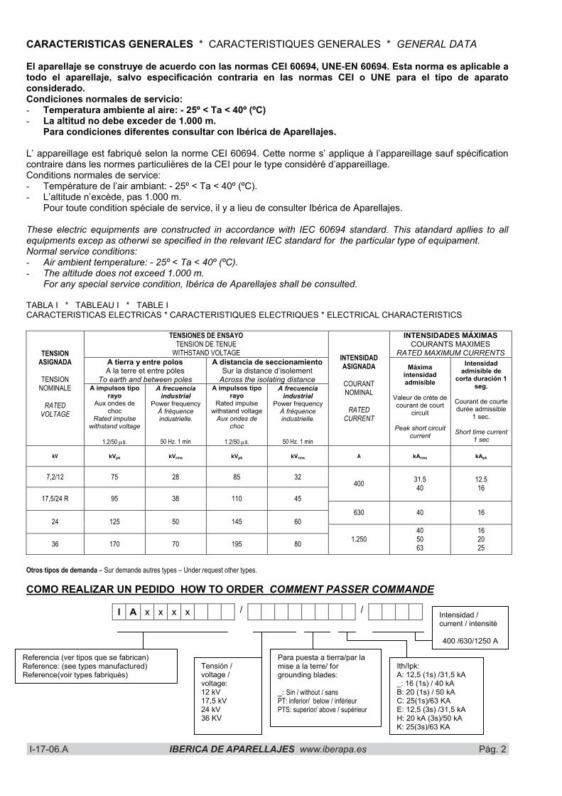
CARACTERISTICAS GENERALES * CARACTERISTIQUES GENERALES * GENERAL DATA
El aparellaje se construye de acuerdo con las normas CEI 60694, UNE-EN 60694. Esta norma es aplicable a todo el aparellaje, salvo especificación contraria en las normas CEI o UNE para el tipo de aparato considerado. Condiciones normales de servicio: - Temperatura ambiente al aire: - 25º < Ta < 40º (ºC) - La altitud no debe exceder de 1.000 m.
Para condiciones diferentes consultar con Ibérica de Aparellajes.
L’ appareillage est fabriqué selon la norme CEI 60694. Cette norme s’ applique à l’appareillage sauf spécification contraire dans les normes particulières de la CEI pour le type considéré d’appareillage. Conditions normales de service: - Température de l’air ambiant: - 25º < Ta < 40º (ºC). - L’altitude n’excède, pas 1.000 m.
Pour toute condition spéciale de service, il y a lieu de consulter Ibérica de Aparellajes.
These electric equipments are constructed in accordance with IEC 60694 standard. This atandard apllies to all equipments excep as otherwi se specified in the relevant IEC standard for the particular type of equipament. Normal service conditions: - Air ambient temperature: - 25º < Ta < 40º (ºC). - The altitude does not exceed 1.000 m.
For any special service condition, Ibérica de Aparellajes shall be consulted.
TABLA I * TABLEAU I * TABLE I CARACTERISTICAS ELECTRICAS * CARACTERISTIQUES ELECTRIQUES * ELECTRICAL CHARACTERISTICS
TENSIONES DE ENSAYO TENSION DE TENUE
WITHSTAND VOLTAGE
INTENSIDADES MÁXIMAS COURANTS MAXIMES
RATED MAXIMUM CURRENTS A tierra y entre polos A la terre et entre póles
To earth and between poles
A distancia de seccionamiento Sur la distance d’isolement
Across the isolating distance
TENSIONASIGNADA
TENSIONNOMINALE
RATEDVOLTAGE
A impulsos tipo rayo
Aux ondes de choc
Rated impulse withstand voltage
1.2/50 �s.
A frecuencia industrial
Power frequency À fréquence industrielle.
50 Hz. 1 min
A impulsos tipo rayo
Rated impulse withstand voltage
Aux ondes de choc
1.2/50 �s.
A frecuencia industrial
Power frequency À fréquence industrielle.
50 Hz. 1 min
INTENSIDADASIGNADA
COURANTNOMINAL
RATEDCURRENT
Máxima intensidad admisible
Valeur de créte de courant de court
circuit
Peak short circuit current
Intensidad admisible de
corta duración 1 seg.
Courant de courte durée admissible
1 sec.
Short time current 1 sec
kV kVpk kVrms kVpk kVrms A kArms kApk
7,2/12 75 28 85 32 400 31.5
4012.5 16
17,5/24 R 95 38 110 45
630 40 16 24 125 50 145 60
36 170 70 195 80 1.250 405063
162025
Otros tipos de demanda – Sur demande autres types – Under request other types.
COMO REALIZAR UN PEDIDO HOW TO ORDER COMMENT PASSER COMMANDE
I A x x x x / /
Tensión / voltage / voltage:12 kV 17,5 kV 24 kV 36 KV
Para puesta a tierra/par la mise a la terre/ for grounding blades:
_: Sin / without / sans PT: inferior/ below / inférieur PTS: superior/ above / supérieur
Ith/Ipk:A: 12,5 (1s) /31,5 kA _: 16 (1s) / 40 kA B: 20 (1s) / 50 kA C: 25(1s)/63 KA E: 12,5 (3s) /31,5 kA H: 20 kA (3s)/50 kA K: 25(3s)/63 KA
Referencia (ver tipos que se fabrican) Reference: (see types manufactured) Reference(voir types fabriqués)
Intensidad / current / intensité
400 /630/1250 A

I-17-06.A IBERICA DE APARELLAJES www.iberapa.es Pág. 3 I-17-06.A IBERICA DE APARELLAJES www:iberapa.es Pág. 5
CARACTERISTICAS FISICAS * CARACTERISTIQUES PHYSIQUES * PHYSICS CHARACTERISTICS
Constan de un bastidor de perfiles de acero indeformable, debidamente tratado contra la oxidación, sobre el cual se montan los aisladores y el eje. Este último sobresale por ambas partes del mismo, con el fin de que la manivela de accionamiento pueda colocarse indistintamente a ambas partes del aparato. El eje está dotado de un dispositivo que fija el recorrido de las cuchillas hasta sus posiciones de abierto y cerrado (trinquete). Los contactos fijos o bornes sirven al mismo tiempo para realizar la conexión del aparato en el circuito donde se instale. Las cuchillas son dobles por polo. De este modo se asegura una presión mayor sobre los contactos fijos en caso de cortocircuito,debido a los esfuerzos electrodinámicos. Están unidas al eje mediante bielas aislantes. Los aisladores son de porcelana de perfilcilíndrico rizado de color marrón. Los aparatos equipados con cuchillas de puesta a tierra, están provistos de un dispositivo de enclavamientomecánico que impide cerrar las cuchillas principales, cuando las de tierra están cerradas o viceversa. IIs comportent un châssis constituté de profils en acier indeformable,dûment traité contre l’oxydation, sur lequel sont montés les isolateurs et l’axe. L’axe depasse depart et d’autre du châssis afin que la poignée d’actionnement puisse s’accoupler indistinctement sur les deux extrémités de l’appareil. L’axe est équipé d’un dispositif de fixation de la course des couperets jusqu’a leurs position d’ouverture et de fermeture (cliquet). Les contacts fixes ou bornes de connexion servent en même temps pour réaliser la connexion l’appareil sur le circuit ou il va être installé. Les couperets sont doubles pour chaque pôle et assurent ainsi une plus forte pression sur les contacts fixes en cas de court-circuit provoqué par les efforts eléctrodynamiques. Ils sont solidarisés à l’axe à l’aide de bielles isolantes. Les isolateurs sont en porcelaine de couleur marron, à profil cylindrique bouclé. Les appareils équipés de couperets de mise à la masse sont munis d’un dispositif d’enclavement mecanique qui empêche la fermeture des couperets principaux quand les couperets de masse sont encore fermés, et viceversa. The framework es constructed from rigid steel sections, which have been submitted to anti-rust treatment,and on these are mounted the insulators and the shaft. The shaft projects from both extremities of the unit so that the activating lever may be located indistinctly at either end of mechanism. The shaft is equipped with a device to define the travel of the blades to their open and closed positions (ratchet). The fixed contacts or terminals serve to constitute the connection of the mechanism in the circuit where it is tu be installed.Double blades are provided per pole. In this way greater pressure is guaranteed on the fixed contacts in the event of a shortcircuit because of the electrodynamic forces. They are linked of the shaft through insulating rods. The insulators are made of brown porcelain with an undulating, cylindrical cross-section. The units fitted with grounding blades are equipped with a mechanical locking device to prevent closure of the main blades while the grounding ones are closed, and viceversa.
DETALLE BORNES PARA LA CONEXIÓN DE LOS TERMINALES DE LOS CONDUCTORES EXTERIORES DETAIL DES BORNES POUR LA CONEXIÓN DES PLOTS DETAIL OF CONNECTION TERMINALS
I-17-06.A IBERICA DE APARELLAJES www.iberapa.es Pág. 4 I-17-06.A IBERICA DE APARELLAJES www:iberapa.es Pág. 6
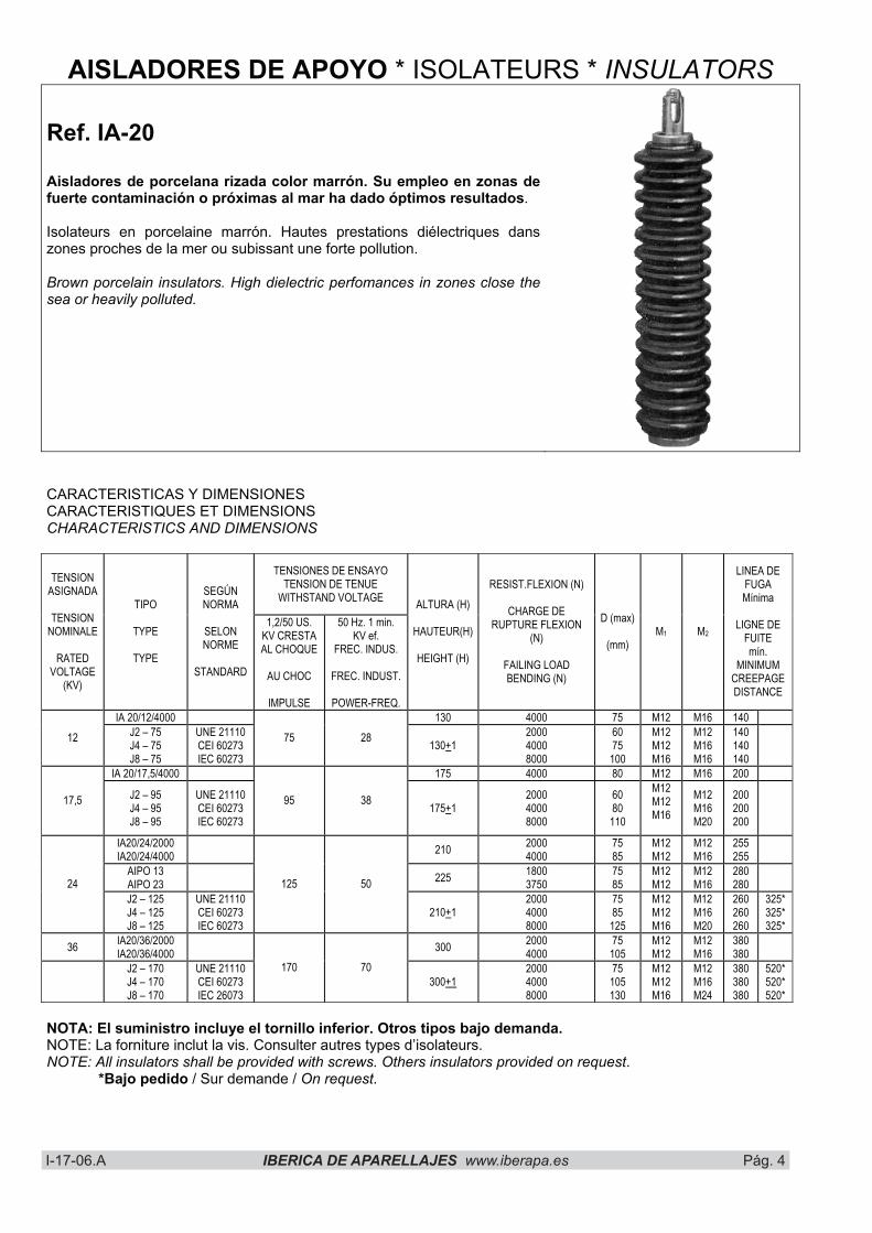
AISLADORES DE APOYO * ISOLATEURS * INSULATORS
Ref. IA-20
Aisladores de porcelana rizada color marrón. Su empleo en zonas de fuerte contaminación o próximas al mar ha dado óptimos resultados.
Isolateurs en porcelaine marrón. Hautes prestations diélectriques dans zones proches de la mer ou subissant une forte pollution.
Brown porcelain insulators. High dielectric perfomances in zones close the sea or heavily polluted.
CARACTERISTICAS Y DIMENSIONES CARACTERISTIQUES ET DIMENSIONS CHARACTERISTICS AND DIMENSIONS
TENSIONES DE ENSAYO TENSION DE TENUE
WITHSTAND VOLTAGE TENSION
ASIGNADA
TENSIONNOMINALE
RATEDVOLTAGE
(KV)
TIPO
TYPE
TYPE
SEGÚNNORMA
SELONNORME
STANDARD
1,2/50 US. KV CRESTA AL CHOQUE
AU CHOC
IMPULSE
50 Hz. 1 min. KV ef.
FREC. INDUS.
FREC. INDUST.
POWER-FREQ.
ALTURA (H)
HAUTEUR(H)
HEIGHT (H)
RESIST.FLEXION (N)
CHARGE DE RUPTURE FLEXION
(N)
FAILING LOAD BENDING (N)
D (max)
(mm)M1 M2
LINEA DE FUGAMínima
LIGNE DE FUITE mín.
MINIMUMCREEPAGEDISTANCE
IA 20/12/4000 130 4000 75 M12 M16 140 12 J2 – 75
J4 – 75 J8 – 75
UNE 21110 CEI 60273 IEC 60273
75 28 130+1200040008000
6075100
M12M12M16
M12M16M16
140140140
IA 20/17,5/4000 175 4000 80 M12 M16 200
17,5 J2 – 95 J4 – 95 J8 – 95
UNE 21110 CEI 60273 IEC 60273
95 38 175+1200040008000
6080110
M12M12M16
M12M16M20
200200200
IA20/24/2000 IA20/24/4000 210 2000
40007585
M12M12
M12M16
255255
AIPO 13 AIPO 23 225 1800
37507585
M12M12
M12M16
28028024
J2 – 125 J4 – 125 J8 – 125
UNE 21110 CEI 60273 IEC 60273
125 50
210+1200040008000
7585125
M12M12M16
M12M16M20
260260260
325* 325* 325*
36 IA20/36/2000 IA20/36/4000 300 2000
400075105
M12M12
M12M16
380380
J2 – 170 J4 – 170 J8 – 170
UNE 21110 CEI 60273 IEC 26073
170 70 300+1
200040008000
75105130
M12M12M16
M12M16M24
380380380
520* 520* 520*
NOTA: El suministro incluye el tornillo inferior. Otros tipos bajo demanda. NOTE: La forniture inclut la vis. Consulter autres types d’isolateurs. NOTE: All insulators shall be provided with screws. Others insulators provided on request.
*Bajo pedido / Sur demande / On request.
I-17-06.A IBERICA DE APARELLAJES www.iberapa.es Pág. 5 I-17-06.A IBERICA DE APARELLAJES www:iberapa.es Pág. 7
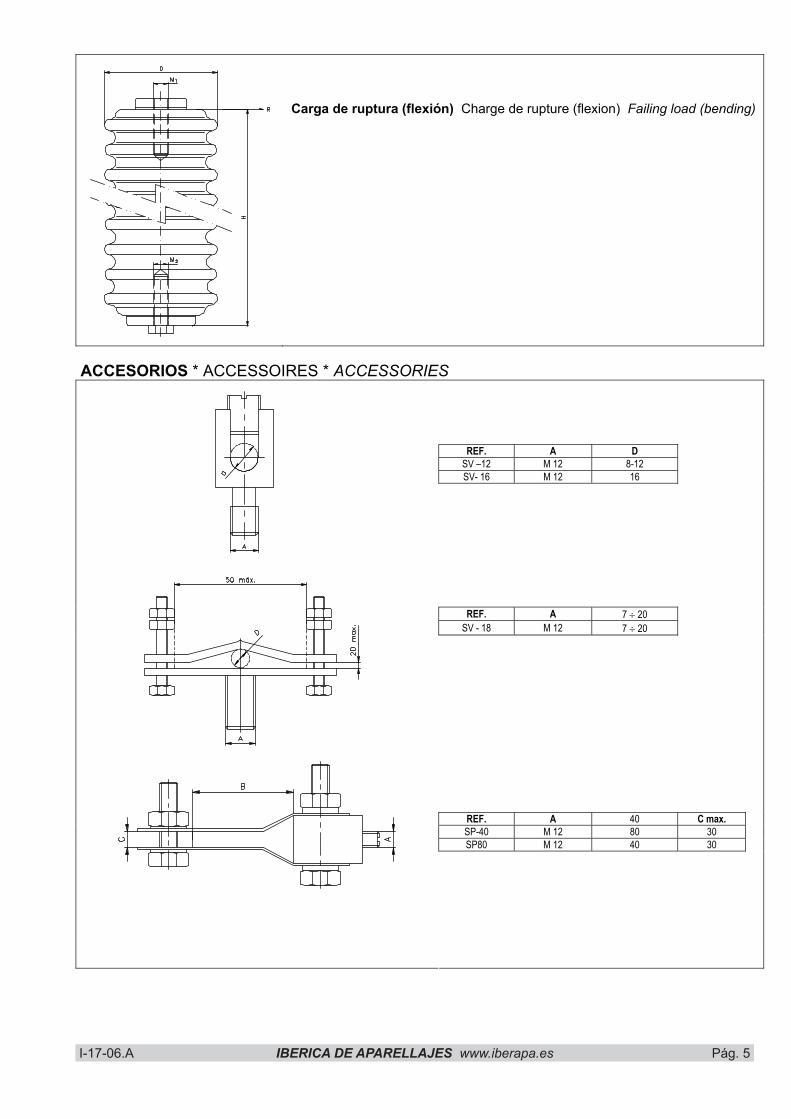
Carga de ruptura (flexión) Charge de rupture (flexion) Failing load (bending)
ACCESORIOS * ACCESSOIRES * ACCESSORIES
REF. A D SV –12 M 12 8-12 SV- 16 M 12 16
REF. A 7 � 20 SV - 18 M 12 7 � 20
REF. A 40 C max. SP-40 M 12 80 30 SP80 M 12 40 30
I-17-06.A IBERICA DE APARELLAJES www.iberapa.es Pág. 6 I-17-06.A IBERICA DE APARELLAJES www:iberapa.es Pág. 8
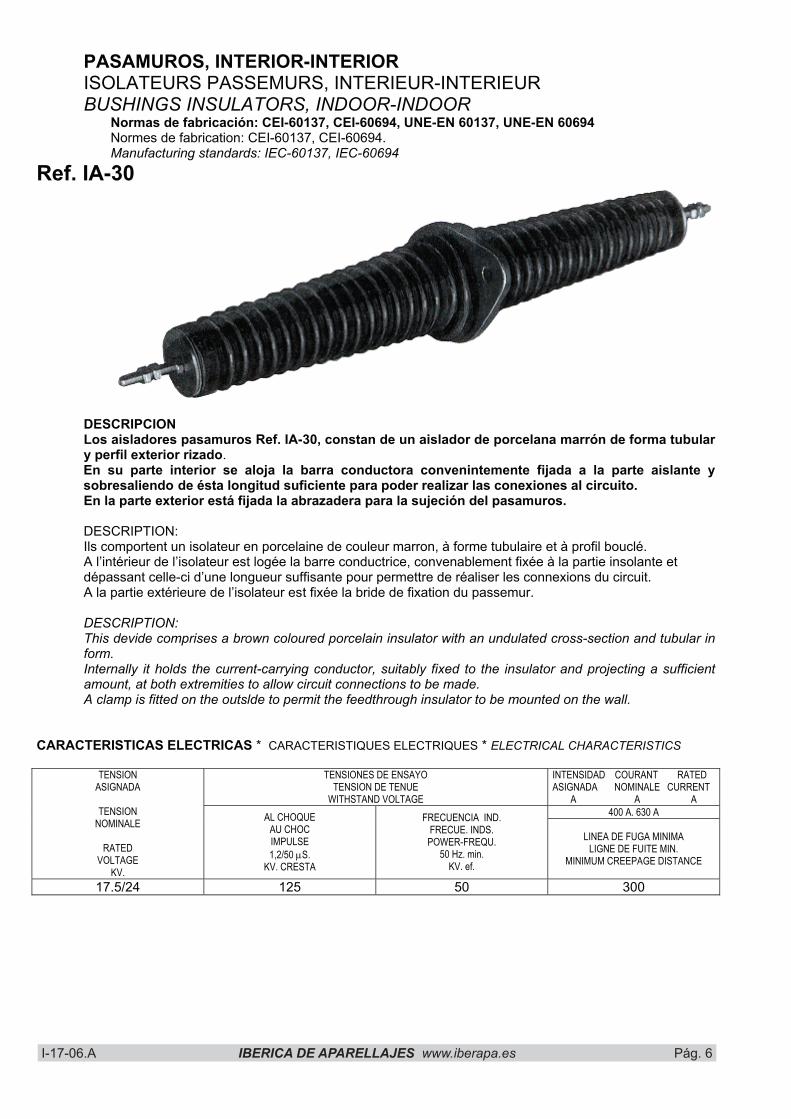
PASAMUROS, INTERIOR-INTERIOR ISOLATEURS PASSEMURS, INTERIEUR-INTERIEUR BUSHINGS INSULATORS, INDOOR-INDOOR
Normas de fabricación: CEI-60137, CEI-60694, UNE-EN 60137, UNE-EN 60694 Normes de fabrication: CEI-60137, CEI-60694. Manufacturing standards: IEC-60137, IEC-60694
Ref. IA-30
DESCRIPCIONLos aisladores pasamuros Ref. IA-30, constan de un aislador de porcelana marrón de forma tubular y perfil exterior rizado.En su parte interior se aloja la barra conductora convenintemente fijada a la parte aislante y sobresaliendo de ésta longitud suficiente para poder realizar las conexiones al circuito. En la parte exterior está fijada la abrazadera para la sujeción del pasamuros.
DESCRIPTION: Ils comportent un isolateur en porcelaine de couleur marron, à forme tubulaire et à profil bouclé. A l’intérieur de l’isolateur est logée la barre conductrice, convenablement fixée à la partie insolante et dépassant celle-ci d’une longueur suffisante pour permettre de réaliser les connexions du circuit. A la partie extérieure de l’isolateur est fixée la bride de fixation du passemur.
DESCRIPTION: This devide comprises a brown coloured porcelain insulator with an undulated cross-section and tubular in form. Internally it holds the current-carrying conductor, suitably fixed to the insulator and projecting a sufficient amount, at both extremities to allow circuit connections to be made. A clamp is fitted on the outslde to permit the feedthrough insulator to be mounted on the wall.
CARACTERISTICAS ELECTRICAS * CARACTERISTIQUES ELECTRIQUES * ELECTRICAL CHARACTERISTICS
TENSIONES DE ENSAYO TENSION DE TENUE
WITHSTAND VOLTAGE
INTENSIDAD COURANT RATED ASIGNADA NOMINALE CURRENT
A A A 400 A. 630 A
TENSIONASIGNADA
TENSIONNOMINALE
RATEDVOLTAGE
KV.
AL CHOQUE AU CHOC IMPULSE1,2/50 �S.
KV. CRESTA
FRECUENCIA IND. FRECUE. INDS. POWER-FREQU.
50 Hz. min. KV. ef.
LINEA DE FUGA MINIMA LIGNE DE FUITE MIN.
MINIMUM CREEPAGE DISTANCE
17.5/24 125 50 300
I-17-06.A IBERICA DE APARELLAJES www.iberapa.es Pág. 7 I-17-06.A IBERICA DE APARELLAJES www:iberapa.es Pág. 9
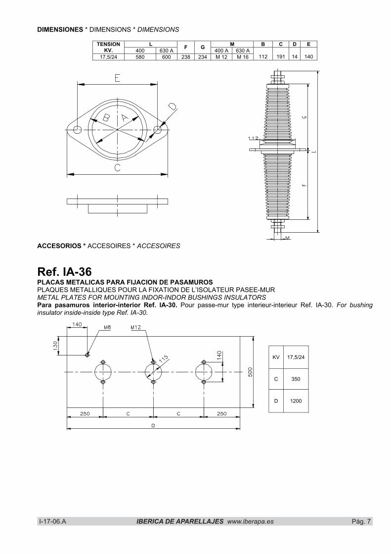
DIMENSIONES * DIMENSIONS * DIMENSIONS
L M B C D E TENSIONKV. 400 630 A F G 400 A 630 A
17,5/24 580 600 238 234 M 12 M 16 112 191 14 140
ACCESORIOS * ACCESOIRES * ACCESOIRES
Ref. IA-36 PLACAS METALICAS PARA FIJACION DE PASAMUROS PLAQUES METALLIQUES POUR LA FIXATION DE L’ISOLATEUR PASEE-MUR METAL PLATES FOR MOUNTING INDOR-INDOR BUSHINGS INSULATORS Para pasamuros interior-interior Ref. IA-30. Pour passe-mur type interieur-interieur Ref. IA-30. For bushing insulator inside-inside type Ref. IA-30.
KV 17,5/24
C 350
D 1200
I-17-06.A IBERICA DE APARELLAJES www.iberapa.es Pág. 8 I-17-06.A IBERICA DE APARELLAJES www:iberapa.es Pág. 10
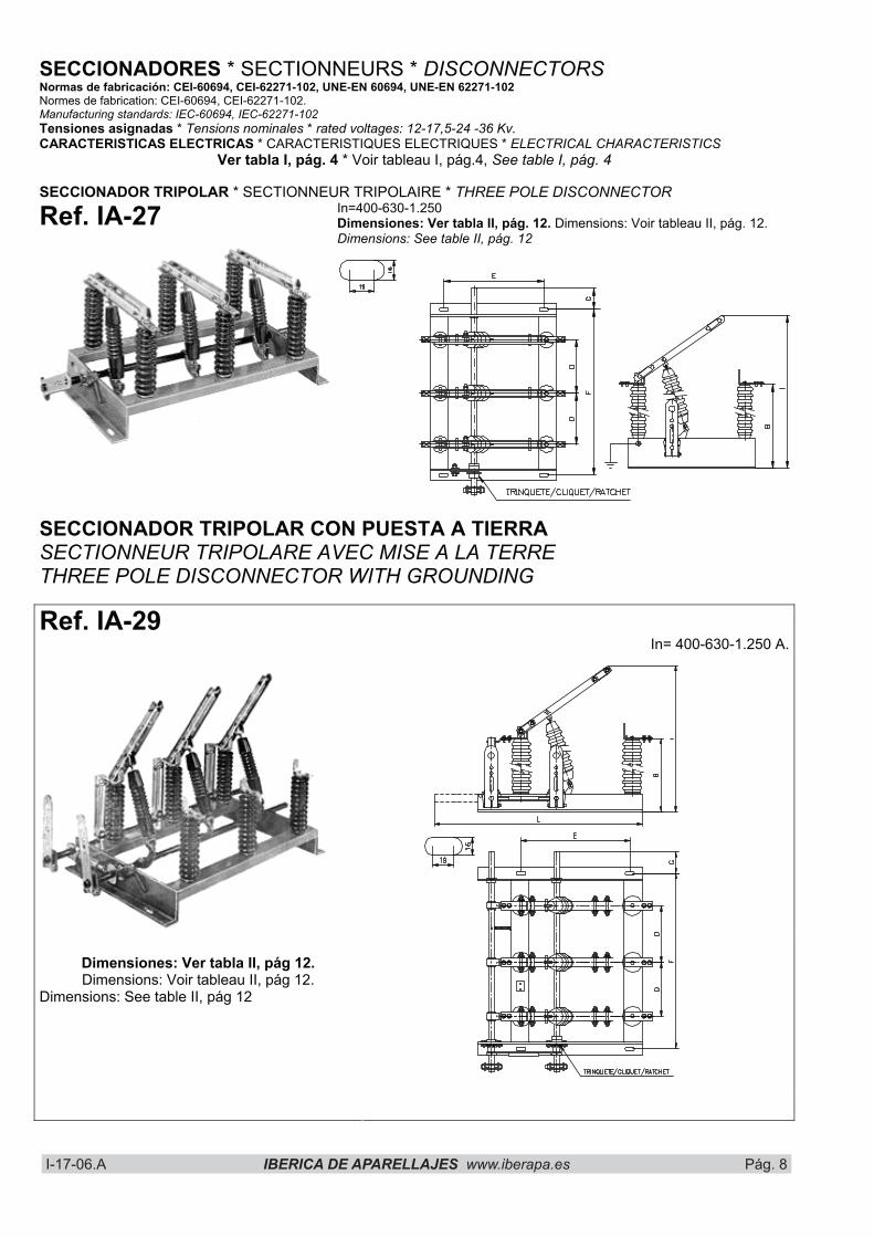
SECCIONADORES * SECTIONNEURS * DISCONNECTORS Normas de fabricación: CEI-60694, CEI-62271-102, UNE-EN 60694, UNE-EN 62271-102 Normes de fabrication: CEI-60694, CEI-62271-102. Manufacturing standards: IEC-60694, IEC-62271-102 Tensiones asignadas * Tensions nominales * rated voltages: 12-17,5-24 -36 Kv. CARACTERISTICAS ELECTRICAS * CARACTERISTIQUES ELECTRIQUES * ELECTRICAL CHARACTERISTICS
Ver tabla I, pág. 4 * Voir tableau I, pág.4, See table I, pág. 4
SECCIONADOR TRIPOLAR * SECTIONNEUR TRIPOLAIRE * THREE POLE DISCONNECTOR
Ref. IA-27 In=400-630-1.250 Dimensiones: Ver tabla II, pág. 12. Dimensions: Voir tableau II, pág. 12. Dimensions: See table II, pág. 12
SECCIONADOR TRIPOLAR CON PUESTA A TIERRA SECTIONNEUR TRIPOLARE AVEC MISE A LA TERRE THREE POLE DISCONNECTOR WITH GROUNDING
Ref. IA-29In= 400-630-1.250 A.
Dimensiones: Ver tabla II, pág 12. Dimensions: Voir tableau II, pág 12.
Dimensions: See table II, pág 12
I-17-06.A IBERICA DE APARELLAJES www.iberapa.es Pág. 9 I-17-06.A IBERICA DE APARELLAJES www:iberapa.es Pág. 11
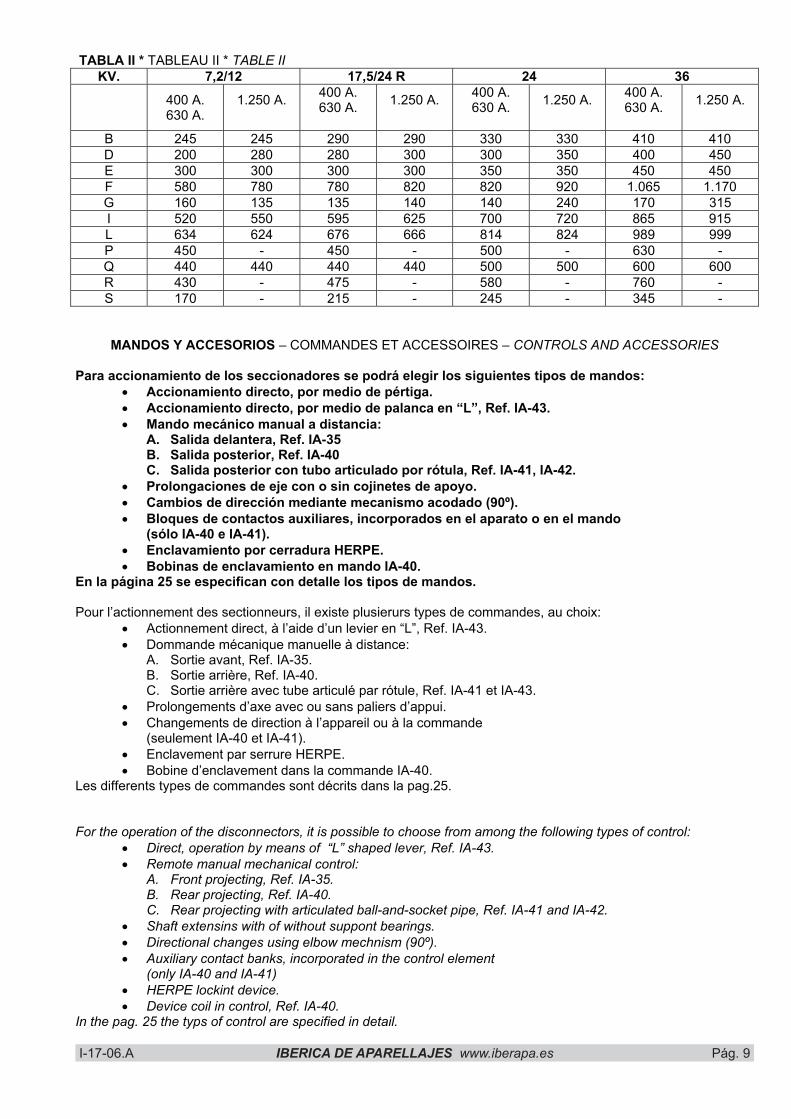
TABLA II * TABLEAU II * TABLE II KV. 7,2/12 17,5/24 R 24 36
400 A. 630 A.
1.250 A. 400 A. 630 A. 1.250 A. 400 A.
630 A. 1.250 A. 400 A. 630 A. 1.250 A.
B 245 245 290 290 330 330 410 410 D 200 280 280 300 300 350 400 450 E 300 300 300 300 350 350 450 450 F 580 780 780 820 820 920 1.065 1.170 G 160 135 135 140 140 240 170 315 I 520 550 595 625 700 720 865 915 L 634 624 676 666 814 824 989 999 P 450 - 450 - 500 - 630 - Q 440 440 440 440 500 500 600 600 R 430 - 475 - 580 - 760 - S 170 - 215 - 245 - 345 -
MANDOS Y ACCESORIOS – COMMANDES ET ACCESSOIRES – CONTROLS AND ACCESSORIES
Para accionamiento de los seccionadores se podrá elegir los siguientes tipos de mandos: � Accionamiento directo, por medio de pértiga. � Accionamiento directo, por medio de palanca en “L”, Ref. IA-43. � Mando mecánico manual a distancia:
A. Salida delantera, Ref. IA-35 B. Salida posterior, Ref. IA-40 C. Salida posterior con tubo articulado por rótula, Ref. IA-41, IA-42.
� Prolongaciones de eje con o sin cojinetes de apoyo. � Cambios de dirección mediante mecanismo acodado (90º). � Bloques de contactos auxiliares, incorporados en el aparato o en el mando
(sólo IA-40 e IA-41). � Enclavamiento por cerradura HERPE. � Bobinas de enclavamiento en mando IA-40.
En la página 25 se especifican con detalle los tipos de mandos.
Pour l’actionnement des sectionneurs, il existe plusierurs types de commandes, au choix: � Actionnement direct, à l’aide d’un levier en “L”, Ref. IA-43. � Dommande mécanique manuelle à distance:
A. Sortie avant, Ref. IA-35. B. Sortie arrière, Ref. IA-40. C. Sortie arrière avec tube articulé par rótule, Ref. IA-41 et IA-43.
� Prolongements d’axe avec ou sans paliers d’appui. � Changements de direction à l’appareil ou à la commande
(seulement IA-40 et IA-41). � Enclavement par serrure HERPE. � Bobine d’enclavement dans la commande IA-40.
Les differents types de commandes sont décrits dans la pag.25.
For the operation of the disconnectors, it is possible to choose from among the following types of control: � Direct, operation by means of “L” shaped lever, Ref. IA-43. � Remote manual mechanical control:
A. Front projecting, Ref. IA-35. B. Rear projecting, Ref. IA-40. C. Rear projecting with articulated ball-and-socket pipe, Ref. IA-41 and IA-42.
� Shaft extensins with of without suppont bearings. � Directional changes using elbow mechnism (90º). � Auxiliary contact banks, incorporated in the control element
(only IA-40 and IA-41) � HERPE lockint device. � Device coil in control, Ref. IA-40.
In the pag. 25 the typs of control are specified in detail.

I-17-06.A IBERICA DE APARELLAJES www.iberapa.es Pág. 10 I-17-06.A IBERICA DE APARELLAJES www:iberapa.es Pág. 12
Ref. IA-200 INTERRUPTOR-SECCIONADOR TRIPOLAR INTERRUPTEUR-SECTIONNEUR TRIPOLAIRE THREE POLE SWITCH-DISCONNECTOR Normas de fabricación: CEI-60694, CEI-62271-102, UNE-EN60694, UNE-EN-62271-102 Normes de fabrication: CEI-60694, CEI-62271-102. Manufacturing standards: IEC-60694, IEC-62271-102.
CARACTERISTICAS GENERALES * CARACTERISTIQUES PRINCIPALES * MAIN CHARACTERISTICS
Interruptor seccionador para protección de transformadores. Gran fiabilidad. Protección contra corrosiones en todas las partes férricas por galvanización y pintura epoxi. Aisladores de porcelana marrón de elevadas características mecánicas. Bobinas de disparo (opcional). Mecanismo por resortes con cierre y apertura bruscas independientes del operador.
Interrupteur-sectionneur pour transformateurs. Grande fiabilité: Protection intégrale contre la rouille de toutes les parties ferreuses par phosphatation et oeinture èpoxy. Isolateurs en porcelaine à caracteristiques mècaniques élèvees. Bobine de déclenchement (sur demande). Commande à ressort, à déclenchement brusque à overture et à fermeture indépendente de l’opérateur.
Transformer switch-disconnector. High reliability. All iron parts are completely protected against rust; they are subjected to aphosphatation treatment and then given an anchoring primer coat and finished with epoxy-resin varnish. Porcelain insulators with outstanding mechanical characteristics. Trip coils (optional). Quick-break quick-make operating mechanism, independent of the operator’s action, satisfies safety regulations.

I-17-06.A IBERICA DE APARELLAJES www.iberapa.es Pág. 11
I-17-06.A IBERICA DE APARELLAJES www:iberapa.es Pág. 13
TIPOS QUE SE FABRICAN * TYPES FABRIQUES * TYPES MANUFACTURED
1.– Aparatos de conexión y desconexión brusca, independiente del operador.1.- Appareils à branchement et débranchement brusque, indépendants de l’opèrateur.1.- Operator-independent, fast make/break devices.
IA-200 sc INTERRUPTOR-SECCIONADOR TRIPOLAR INTERRUPTEUR-SECTIONNEUR TRIPOLAIRE THREE POLE SEITCH-DISCONNECTOR
IA-200 sc F
INTERRUPTOR-SECCIONADOR TRIPOLAR CON DISPARO AUTOMATICO POR FUSION DE FUSIBLE (MEDIDAS DIN). INTERRUPTEUR-SECTIONNEUR TRIPOLAIRE A DECLENCHEMENT AUTOMATIQUE PAR GRILLAGE DU FUSIBLE (MESURES DIN)- THREE POLE SWITCH-DISCONNECTOR WITH AUTOMATIC FUSE TRIPPING (DIN MEASUREMENTS).
IA- 200 sc FR
INTERRUPTOR-SECTIONADOR TRIPOLAR CON DISPARO AUTOMATICO POR MEDIO DE RELES Y FUSIBLES (MEDIDAS DIN).PUEDE SUMINISTRARSE EQUIPADO CON DOS O TRES RELES TIPO RTE. INTERRUPTEUR-SECTIONNEUR TRIPOLAIRE A DECLENCHEMENT AUTOMATIQUE COMMANDE PAR RELAIS ET FUSIBLES (MESURES DIN). IL EST DISPONIBLE EQUIPE DE DEUX OU TROIS RELAIS TYPE RTE. THREE POLE SWITCH-DISCONNECTOR/WITH AUTOMATIC RELAY AND FUSE TRIPPING (DIN MEASUREMENTS). CAN BE SUPPLIED EQUIPPED WITH TWO OR THREE RELAYS TYPE RTE.
NOTA * NOTE * NOTE Bajo demanda, se suministran con cuchillas de puesta a tierra. Sur demande, ils sont livrés sur commande équipés de couperets de mise à la masse. On order, they can be supplied with grounding blades.
CARACTERISTICAS ELECTRICAS * CARACTERISTIQUES ELECTRIQUES * ELECTRICAL CHARACTERISTICSTENSIONES DE ENSAYO
TENSION DE TENUE WITHSTAND VOLTAGE
MASA Y ENTRE POLOS A LA TERRE ET ENTRE POLES
TO EARTH AND BETWEEN POLES
DISTANCIA SECCIONAMIENTO SUR LA DISTANCE DE
SECTIONNEMENT ACROS THE ISOLATING
DISTANCE
TENSIONASIGNADA
TENSIONNOMINALE
RATED VOLTAGE
KV
AL CHOQUE AU CHOC IMPULSE1.2/50 �s
KV CRESTA
FREC.INDUST.FRECUE.INDUS.
POWER-FREQU.
50 Hz. 1MIN. KV eff.
AL CHOQUE AU CHOC IMPULSE1.2/50 �s.
KV CRESTA
FREC.INDUST.FRECUE.INDUS.
POWER-FREQU.
50 Hz. 1 min. KV eff.
INTENSIDAD ASIGNADA
COURANT NOMINAL
RATED CURRENT
A
INTENSIDAD ADMISIBLE DE
C.C.
COURANT DE CRETE
PEAK CURRENT
KA CRESTA
INTENSIDAD ADMISIBLE
CORTA DURANCION
COURANT COURTE DUREE
SHORT TIME CURRENT
1 seg. KA eff.
12 75 28 85 32 400 17,5/24 R 95 38 110 45 400
24 125 50 145 60 400 36 170 70 195 80 400
2531,25
40
1012.516
PUESTAS A TIERRA * MISE A LA TERRE * EARTHIN BLADES
Ref. PAT IA 200 : - Tensión / Tension / Rated voltage- N: Sin poder de cierre / Sans pouvoir de fermeture / Without making capaciy- B: Con poder de cierre / Avec pouvoir de fermeture / With making capqcity (40 KA cr.)

I-17-06.A IBERICA DE APARELLAJES www.iberapa.es Pág. 12 I-17-06.A IBERICA DE APARELLAJES www:iberapa.es Pág. 14
CARACTERISTICAS DE CORTE PARA INTERRUPTORES CARACTERISTIQUES DE COUPE POUR INTERRUPTEURS BREAKING CHARACTERISTICS FOR SWITCH
TENSIONASIGNADA
KVTENSION
NOMINALE KV RATED
VOLTAGE KV
CARGAACTIVA
cos.� = 0,7 A. ef.
CHARGE ACTIVE cos. � =0,7
A. ef. ACTIVE LOAD
cos. � = 0,7 A rms.
TRANSFORMADORES EN VACIO
cos � < 0,15 A. ef.
TRANSFORMATEUS A VIDE cos � <0,15
A. ef. UNLOADED TRANSFORMES
cos. � <0,15 A rms.
LINEAS AEREAS Y CABLES EN
VACIO A. ef.
LIGNES AÉ-RIENNES ET CABLES A VIDE
A. ef. UNLOADED OVERHEAD
LINES AND CABLES A rms.
12 400 10 16 17,5/24 R 400 6,5 10
24 400 6,5 10 36 200 4 6,3
DIMENSIONES * DIMENSIONS * DIMENSIONS KV 12 17,5/24 R 24 36 B 240 290 330 425 D 240 290 330 420 E 350 350 350 450 F 680 790 860 1.065G 110 120 120 170 I 730 695 800 940 L 465 740 790 1.015
Ref. IA 200 sc
KV 12 17,5/24 R 24 36 B 240 290 330 425 C 325 470 470 570 D 240 290 330 420 E 300 400 400 590 F 700 800 880 1.065G 100 150 110 170 I 620 695 800 975 L 1.210 1.405 1.455 1.710
Ref. IA-200 sc F
Ref. IA-200 sc FR

I-17-06.A IBERICA DE APARELLAJES www.iberapa.es Pág. 13 I-17-06.A IBERICA DE APARELLAJES www:iberapa.es Pág. 15
MANDOS Y ACCESORIOS * COMANDES ET ACCESOIRES * CONTROLS AND ACCESSORIES
� Accionamiento directo por medio de palanca en “L”, Ref. IA-43� Mando mecánico manual a distancia:
A. Salida delantera Ref. IA-35 C (IA-200 sc) o IA-35/200 (IA-200 scF/FR). B. Salida posterior Ref. IA-40 C (IA-200 sc) o IA-40/200 (IA-200 sc F/FR).C. Salida posterior con tubo articulado por rótula Ref. IA-41 C (IA-200 sc) o IA-41/200 (IA/200 sc F/FR).D. Salida delantera con tubo articulado por rótula Ref. IA-42 C (IA-200 sc) o IA-42/200 (IA-200 sc F/FR).
� Prolongaciones de eje con o sin cojinetes de apoyo .� Bloques de contactos auxiliares incorporados en el aparato o en el mando (sólo IA-40 e IA-41).� Bobinas de disparo.� Enclavamientos por cerradura HERPE.En la pág. 25 se especifican con detalle los tipo de mandos.
� Actionnement direct, à l’aide d’un levier en “L”, Ref. IA-43� Commande mécanique manuelle à distance:
A) Sortie avant Ref. IA-35/200 (IA-200 sc F/FR) ou IA-35 C (IA-200 sc). B) Sortie arrière Ref. IA-40/200 (IA-200 sc F/FR) ou IA-40 C (IA-200 sc ). C) Sortie arrière avec tube articulé par rótule Ref. IA-41/200 (IA-200 sc FR) ou IA-41 C (IA-200 sc). D) Sortie avnat avec tube articulé par rotule Ref. IA-42 C (IA-200 sc) ou IA-42/200 (IA-200 sc F/FR).
� Prolongations d’axe avec au sans paliers d’appui � Blocs de contacts auxiliaires incorporés à l’appareil ou à la commande (seulement IA-40 et IA-41). � Bobines de déclenchement. � Enclavement par serrure HERPE. Les differents types de commandes sont décrits en dátail dans la pag.25.
� Direct operation by means of L-shaped, lever, Ref. IA-43. � Remote manual mechanical control:
A) Front projecting Ref. IA-35/200 (IA-200 sc F/FR) or IA-35 C (IA-200 sc). B) Rear projecting Ref. IA-40/200 (IA-200 sc FR) or IA-40 C (IA-200 sc). C) Rear projecting with ball and socket articulated pipe Ref. IA-41/200 or IA-41 C (IA-200 sc). D) Front projecting with ball and socket articulated pipe Ref. IA-42 C (IA.200 sc) or Ref. IA-42/200 (IA-200 sc F/FR).
� Shaft extenders with or without support bearings � Auxiliari contact banks incorporated in unit of control element (only IA-40 and IA-41). � Trip coils. � HERPE type locking device. The different kinds of control elements are described in the pag. 25.

I-17-06.A IBERICA DE APARELLAJES www.iberapa.es Pág. 14 I-17-06.A IBERICA DE APARELLAJES www:iberapa.es Pág. 16
INTERRUPTORES SECCIONADORES DE USO GENERAL INTERRUPTEUR-SECTIONNEUR D’USAGE GENERAL GENERAL PURPOSE SWITCHES Ref. RI/RIF Normas de fabricación: CEI-60694, CEI-62271-102, UNE-EN-60694, UNE-EN-62271-102 Normes de fabrication: CEI-60694, CEI-62271-102. Manufacturing standards: IEC-60694, IEC-62271-102.
RI RIF
GENERALIDADES Los interruptores-seccionadores tipo RI, responden al principio de autosoplado, consistente en generar el aire comprimido necesario para la extinción del arco, durante la carrera de apertura. Es un aparato típico de maniobra, adecuado para instalaciones de interior. Los interruptores autoneumáticos tipo RIF, de corte visible en aire, se derivan de los interruptores tipo RI. Están equipados de uno o dos mecanismos de retención del resorte y relés primarios térmicos del tipo RTE4. Disponen de cortacircuitos de alto poder de corte tipo DIN. Tanto los relés como los cortacircuitos van montados directamente sobre los polos del interruptor. La desconexión del interruptor se produce, en caso de sobrecargas, bajo la acción de los relés térmicos y, en caso de cortacircuito, por la fusión de cualquiera de los fusibles.
GÉNERALITES. Les interrupteurs – sectionneurs type RI, répondent au principe d’autosoufflage, consistant en la création de l’air comprimé nécessaire pour l’extinction de l’arc, pendant la course d’ouverture. C’est un appareil typique de manoeuvre, adéquat pour installations d’intérieur. Les interrupteurs auto-pneumatiques du type RIF, de coupe visible à l’air, dérivent des interrupteurs type RI. Ils sont équipés d’un ou de deux mécanismes de rétention du ressort et de relais primaires thermiques du type RTE4. Ils disposent de fusibles à haut pouvoir de coupure type DIN. Aussi bien les relais que les courts-circuits sont montés directement sur les pôles de l’interrupteur. La déconnexion de l’interrupteur se produit, en cas de surcharges, sous l’action des relais thermiques et, en cas de court-circuit, par la fusion de n’importe lequel des fusibles.
GENERAL INFORMATION The RI switch-disconnectors work on the principle of self-blasting, which consists of generating the compressed air necessary to extinguish the arc during the opening operation. It is a typical operating device which is suitable for interior installations. The RIF self-blasting switches, with visible air breaking, are derived from the RI switches. They are fitted with one or two spring retention mechanisms and RTE4 primary thermal relays. They have DIN type fuses with a high breaking capacity. The relays and short-circuits are directly assembled on the poles of the switch. In the case of an overload, the switch is deactivated by the action of the thermal relays, and in the case of a short-circuit, by any one of the fuses blowing.
I-17-06.A IBERICA DE APARELLAJES www.iberapa.es Pág. 15 I-17-06.A IBERICA DE APARELLAJES www:iberapa.es Pág. 17
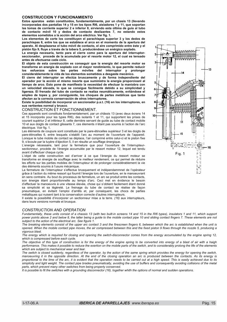
CONSTRUCCION Y FUNCIONAMIENTO Estos aparatos están constituidos, fundamentalmente, por un chasis 13 (llevando incorporadas dos pantallas 14 y 15 en los tipos RI6, aisladores 1 y 11, que soportan las tomas de corriente superior 2 e inferior 8, sirviendo esta última de guía al tubo de contacto móvil 10 y dedos de contacto deslizantes 7, no estando estos elementos sometidos a la acción del arco eléctrico. Ver fig. 1. Los elementos de corte los constituyen el parachispas superior 3 y los dedos de parachispas 6, entre los que se establece el arco en el momento de la apertura del aparato. Al desplazarse el tubo móvil de contacto, el aire comprimido entre éste y el pistón fijo 9, fluye a través de la tobera 5, produciéndose un enérgico soplado. La energía necesaria, tanto para el cierre como para la apertura del interruptor-seccionador, procede de la acumulada por el resorte motor 12, el cual es tensado antes de efectuarse cada ciclo. El objeto de esta construcción es conseguir que la energía del resorte motor se transforme en energía de soplado con el mayor rendimiento, lo que permite reducir los esfuerzos sobre las partes móviles del interruptor y prolongar considerablemente la vida de los elementos sometidos a desgaste mecánico. El cierre del interruptor se efectúa bruscamente y de forma independiente del operador por la acción el mismo resorte que suministra la energía proporcioanl al tiempo de arco. Esto pone de manifiesto la necesidad de efectuar la maniobra con un velocidad elevada, lo que se consigue fácilmente debido a su simplicidad y ligereza. El frenado del tubo de contacto se realiza neumáticamente, evitándose el empleo de topes y, por consiguiente, los choques de partes metálicas que tanto afectan aa la correcta conservación de otros interruptores. Existe la posibilidad de incorporar un seccionador p.a.t. (16) en los interruptores, en sus vertientes normal y brusco.CONSTRUCTION ET FONCTIONNEMENT. Ces appareils sont constitués fondamentalement, par un châssis 13 (avec deux écrans 14 et 15 incorporés pour les types RI6), des isolants 1 et 11, qui supportent les prises de courant supériur 2 et inférieur 8, cette dernière servant de guide au tube de contact mobile 10 et aux doigts de contact glissants 7, ces élements n’étant pas soumis à l’action de l’arc électrique. Voir fig. 1. Les éléments de coupure sont constitués par le pare-étincelles supérieur 3 et les doigts de pare-étincelles 6, entre lesquels s’etablit l’arc au moment de l’ouverture de l’appareil. Lorsque le tube mobile de contact se déplace, l’air comprimé entre celui-ci et le piston fixe 9, s’écoule par la tuyère d’éjection 5, il en résulte un soufflage énergique. L’energie nécessaire, tant pour la fermeture que pour l’ouverture de l’interrupteur-sectionneur, procède de l’énergie accumulée par le ressort moteur 12, lequel est tendu avant d’effectuer chaque cycle. L’objet de cette construction est d’arriver à ce que l’énergie du ressort moteur se transforme en énergie de soufflage avec le meilleur rendement, ce qui permet de réduire les efforts sur les parties mobiles de l’interrupteur et de prolonger considérablement la vie des éléments soumis à l’usure mécanique. La fermeture de l’interrupteur s’effectue brusquement et indépendammnet de l’opérateur grâce à l’action du même ressort qui fournit l’énergie lors de l’ouverture, en le manoeuvrant en sens contraire. Au bout du processus de fermeture, un arc se produit entre les contacts, son énergie étant proportionnelle au temps d’arc. Ceci met en évidence le besoin d’effectuer la manoeuvre à une vitesse élevée, chose qui s’obtient facilement étant donné sa simplicité et sa légèreté. Le freinage du tube de contact se réalise de façon pneumatique, en évitant l’emploi d’arrêts et, par conséquent, les chocs de parties métalliques qui nuisent tant à la conservation correcte d’autres interrupteurs. Il existe la possibilité d’incorporer un sectionneur mise a la terre. (16) aux interrupteurs, dans leurs versions normale et brusque.
CONSTRUCTION AND OPERATION Fundamentally, these units consist of a chassis 13 (with two built-in screens 14 and 15 in the RI6 types), insulators 1 and 11, which support power points above 2 and below 8, the latter being a guide to the mobile contact pipe 10 and sliding contact fingers 7. These elements are not subject to the action of the electrical arc. See figure 1. The breaking elements consist of the upper arc contact 3 and the firescreen fingers 6, between which the arc is established when the unit is opened. When the mobile contact pipe moves, the air compressed between this and the fixed piston 9 flows through the nozzle 5, producing a vigorous blast. The energy which is required for closing and opening the switch-disconnector comes from the energy accumulated by the engine spring 12, which is compressed before each cycle. The objective of this type of construction is for the energy of the engine spring to be converted into energy of a blast of air with a haigh performance. This makes it possible to reduce the exertion on the mobile parts of the switch, and to considerably prolong the life of the elements which are subject to mechanical wear and tear. The switch is closed suddenly, regardless of the operator, by the action of the same spring which provides the energy for opening the switch, manoeuvring it in the opposite direction. At the end of the closing operation an arc is produced between the contacts. As its energy is proportional to the time of the arc, it is evident that the operation needs to be carried out at a high speed. This is easily achieved due to its simplicity and light weight. The contact pipe brades pneumatically, avoiding the use of buffers and consequently avoiding collisions of the metal parts, which prevent many other switches from being properly conserved. It is possible to fit the switches with a grounding disconnector (16), together whith the options of normal and sudden operations.
I-17-06.A IBERICA DE APARELLAJES www.iberapa.es Pág. 16 I-17-06.A IBERICA DE APARELLAJES www:iberapa.es Pág. 18
CONSTRUCCION Y FUNCIONAMIENTO DE LOS RIF Durante la maniobra de conexión, el resorte motor es tensado manualmente por medio de una manivela hasta que pasa de cierto punto; en ese momento se descarga parcialmente provocando la conexión brusca del interruptor, independientemente del operador. La descarga del resorte es limitada por un mecanismo de retención, conservando energía suficiente para la maniobra de desconexión del aparato, la cual puede realizarse a pie de aparato por medio de una manivela o a distancia por un electroimán. CONSTRUCTION ET FONCTIONNEMENT DES RIF. Pendant la manoeuvre de raccordement, le ressort moteur est tendu manuellement au moyen d’une manivelle jusqu’au passage d’un certain point; à ce moment il se décharge partiellement provoquant la connexion brusque de l’interrupteur, indépendamment de l’opérateur. La décharge du ressort est limitée par un mécanisme de rétention, conservant de l’énergie suffisante pour la manoeuvre de déconnexion de l’appareil, laquelle peut être réalisée à côté de l’appareil au moyen d’une manivelle ou à distance par un électroaimant. CONTRUCTION AND OPERATION OF THE RIF During the activation operation, the engine spring is manually tautened beyond a certain point by means of a crank; at this moment it is partially released, resulting in the sudden activation of the switch, regardless of the operator. The release of the spring is limited by a retention mechanism, and conserves sufficient energy for the deactivation operation ofthe unit. This can be carried out from right beside the unit by means of a crank, or at a distance with an electromagnet.
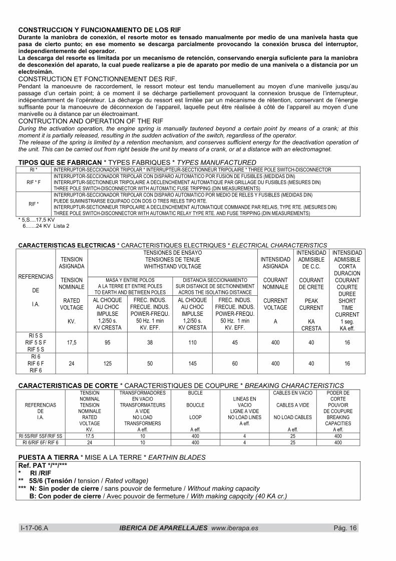
TIPOS QUE SE FABRICAN * TYPES FABRIQUES * TYPES MANUFACTUREDRI * INTERRUPTOR-SECCIONADOR TRIPOLAR * INTERRUPTEUR-SECCTIONNEUR TRIPOLAIRE * THREE POLE SWITCH-DISCONNECTOR
RIF * F INTERRUPTOR-SECCIONADOR TRIPOLAR CON DISPARO AUTOMATICO POR FUSION DE FUSIBLES (MEDIDAS DIN) INTERRUPTUR-SECTIONNEUR TRIPOLAIRE A DECLENCHEMENT AUTOMATIQUE PAR GRILLAGE DU FUSIBLES (MESURES DIN) THREE POLE SWITCH-DISCONNECTOR WITH AUTOMATIC FUSE TRIPPING (DIN MEASUREMENTS)
RIF * INTERRUPTOR-SECCIONADOR TRIPOLAR CON DISPARO AUTOMATICO POR MEDIO DE RELES Y FUSIBLES (MEDIDAS DIN) PUEDE SUMINISTRARSE EQUIPADO CON DOS O TRES RELES TIPO RTE. INTERRUPTUR-SECTIONNEUR TRIPOLAIRE A DECLENCHEMENT AUTOMATIQUE COMMANDE PAR RELAIS, TYPE RTE. (MESURES DIN) THREE POLE SWITCH-DISCONNECTOR WITH AUTOMATIC RELAY TYPE RTE. AND FUSE TRIPPING (DIN MEASUREMENTS)
* 5,S....17,5 KV 6.......24 KV Lista 2
CARACTERISTICAS ELECTRICAS * CARACTERISTIQUES ELECTRIQUES * ELECTRICAL CHARACTERISTICS TENSIONES DE ENSAYO TENSIONES DE TENUE WHITHSTAND VOLTAGE
MASA Y ENTRE POLOS A LA TERRE ET ENTRE POLES
TO EARTH AND BETWEEN POLES
DISTANCIA SECCIONAMIENTO SUR DISTANCE DE SECTIONNEMENT
ACROS THE ISOLATING DISTANCE
REFERENCIAS
DE
I.A.
TENSIONASIGNADA
TENSIONNOMINALE
RATEDVOLTAGE
KV.
AL CHOQUE AU CHOC IMPULSE1,2/50 s.
KV CRESTA
FREC. INDUS. FRECUE. INDUS. POWER-FREQU.
50 Hz. 1 min KV. EFF.
AL CHOQUE AU CHOC IMPULSE1,2/50 s.
KV CRESTA
FREC. INDUS. FRECUE. INDUS. POWER-FREQU.
50 Hz. 1 min KV. EFF.
INTENSIDADASIGNADA
COURANTNOMINALE
CURRENTVOLTAGE
A
INTENSIDADADMISIBLE
DE C.C.
COURANTDE CRETE
PEAKCURRENT
KACRESTA
INTENSIDADADMISIBLE
CORTADURACIONCOURANTCOURTEDUREESHORT
TIMECURRENT
1 seg. KA eff.
RI 5 S RIF 5 S F RIF 5 S
17,5 95 38 110 45 400 40 16
RI 6 RIF 6 F RIF 6
24 125 50 145 60 400 40 16
CARACTERISTICAS DE CORTE * CARACTERISTIQUES DE COUPURE * BREAKING CHARACTERISTICS
REFERENCIASDEI.A.
TENSIONNOMINALTENSION
NOMINALERATED
VOLTAGEKV.
TRANSFORMADORES EN VACIO
TRANSFORMATEURS A VIDE
NO LOAD TRANSFORMERS
A eff.
BUCLE
BOUCLE
LOOP
A eff.
LINEAS EN VACIO
LIGNE A VIDE NO LOAD LINES
A eff.
CABLES EN VACIO
CABLES A VIDE
NO LOAD CABLES
A eff.
PODER DE CORTE
POUVOIRDE COUPURE
BREAKINGCAPACITIES
A eff. RI 5S/RIF 5SF/RIF 5S 17.5 10 400 4 25 400
RI 6/RIF 6F/ RIF 6 24 10 400 4 25 400
PUESTA A TIERRA * MISE A LA TERRE * EARTHIN BLADES Ref. PAT */**/*** * RI /RIF ** 5S/6 (Tensión / tension / Rated voltage) *** N: Sin poder de cierre / sans pouvoir de fermeture / Without making capacity B: Con poder de cierre / Avec pouvoir de fermeture / With making capqcity (40 KA cr.)
I-17-06.A IBERICA DE APARELLAJES www.iberapa.es Pág. 17 I-17-06.A IBERICA DE APARELLAJES www:iberapa.es Pág. 19
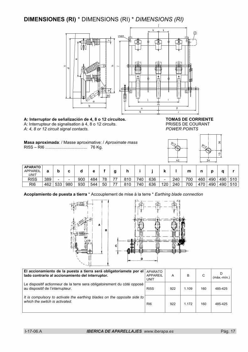
DIMENSIONES (RI) * DIMENSIONS (RI) * DIMENSIONS (RI)
A: Interruptor de señalización de 4, 8 o 12 circuitos. A: Interrupteur de signalisation à 4, 8 o 12 circuits. A: 4, 8 or 12 circuit signal contacts.
TOMAS DE CORRIENTE PRISES DE COURANT POWER POINTS
Masa aproximada: / Masse aproximative: / Aproximate massRI5S – RI6 .................................... 76 Kg.
APARATO APPAREIL
UNITa b c d e f g h i j k l m n p q r
RI5S 389 - - 900 484 78 77 810 740 636 - 240 700 460 490 490 510RI6 462 533 980 930 544 50 77 810 740 636 120 240 700 470 490 490 510
Acoplamiento de puesta a tierra * Accouplement de mise à la terre * Earthing blade connection
APARATO APPAREILUNIT
A B C D(máx.-mín.)
RI5S 922 1.109 160 485-425
El accionamiento de la puesta a tierra será obligatoriamete por el lado contrario al accionamiento del interruptor.
Le dispositif actionneur de la terre sera obligatoirement du còté opposé au dispositif de l’interrupteur.
It is compulsory to activate the earthing blades on the opposite side to which the switch is activated.
RI6 922 1.172 160 485-425

I-17-06.A IBERICA DE APARELLAJES www.iberapa.es Pág. 18 I-17-06.A IBERICA DE APARELLAJES www:iberapa.es Pág. 20
DIMENSIONES (RIF) * DIMENSIONS (RIF) * DIMENSIONS (RIF)
� Interruptor fin de curso. (Sólo para aparatos motorizados.)
� Contactos de señalización. (Sobre pedido)
� Tomas de corriente. � Motor reductor.
(Sobre pedido) � Relé RTE4. (Sólo en RIF.) � Fusible DIN 43625. � Pantalla aislante. � Bobina de disparo.
(Sobre pedido.) � Seccionador de p.a.t. (Sobre pedido.)
� Interrupteur d’arrêt. (Uniquement pour appareils motorisés).
� Contacts de signalisation. (sur commande)
� Prises de courant. � Moteur réducteur.
(sur commande) � Relais RTE4. (Seulement en RIF.) � Fusible DIN 43625. � Écran isolant. � Bobine d’allumage.
(Sur commande) � Sectionneur de m.a.t.
(Sur commande).
� End of course switch. (Only for motorised units)
� Signal contacts (On request)
� Power point. � Reduction motor.
(On demand) � RTE4 relay (Only in RIF) � DIN 43625 fuse. � Insulating screen. � Tripping reel.
(On demand) � Earthing swicth.
(On demand)
Tipo Type a b c d e f g h RIF5SFRIF5S - 80 458 467 580 - 1.060 -
RIF6FRIF6 305 50 483 520 622 650 1.226 85
Masa aproximada...... 150 Kg. Masse aproximative... 150 Kg. Approximate mass..... 150 Kg.
TOMAS DE CORRIENTE PRISES DE COURANT POWER POINTS
I-17-06.A IBERICA DE APARELLAJES www.iberapa.es Pág. 19 I-17-06.A IBERICA DE APARELLAJES www:iberapa.es Pág. 21
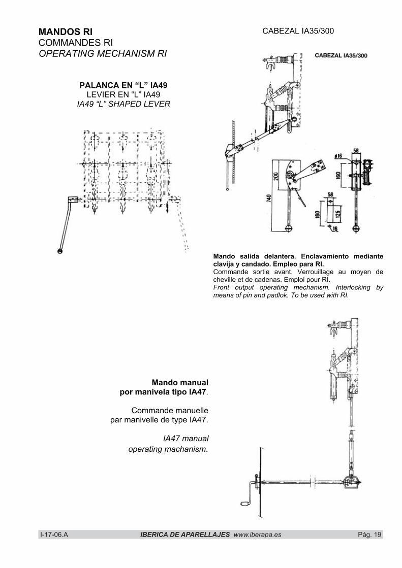
MANDOS RI COMMANDES RI OPERATING MECHANISM RI
PALANCA EN “L” IA49 LEVIER EN “L” IA49
IA49 “L” SHAPED LEVER
CABEZAL IA35/300
Mando salida delantera. Enclavamiento mediante clavija y candado. Empleo para RI. Commande sortie avant. Verrouillage au moyen de cheville et de cadenas. Emploi pour RI. Front output operating mechanism. Interlocking by means of pin and padlok. To be used with RI.
Mando manualpor manivela tipo IA47.
Commande manuellepar manivelle de type IA47.
IA47 manualoperating machanism.
I-17-06.A IBERICA DE APARELLAJES www.iberapa.es Pág. 20 I-17-06.A IBERICA DE APARELLAJES www:iberapa.es Pág. 22
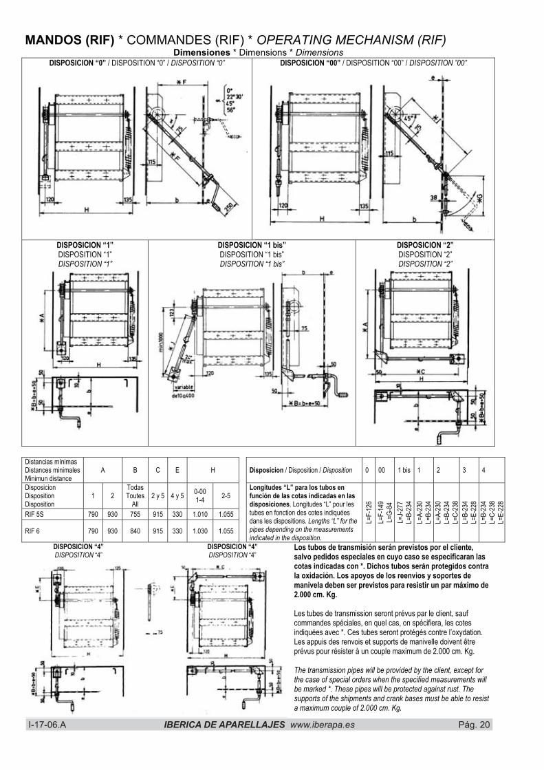
MANDOS (RIF) * COMMANDES (RIF) * OPERATING MECHANISM (RIF) Dimensiones * Dimensions * Dimensions
DISPOSICION “0” / DISPOSITION “0” / DISPOSITION “0” DISPOSICION “00” / DISPOSITION “00” / DISPOSITION ”00”
DISPOSICION “1” DISPOSITION “1” DISPOSITION “1”
DISPOSICION “1 bis” DISPOSITION “1 bis” DISPOSITION “1 bis”
DISPOSICION “2” DISPOSITION “2” DISPOSITION “2”
Distancias mínimas Distances minimales Minimun distance
A B C E H Disposicion / Disposition / Disposition 0 00 1 bis 1 2 3 4
DisposicionDisposition Disposition
1 2 TodasToutes
All2 y 5 4 y 5 0-00
1-4 2-5
RIF 5S 790 930 755 915 330 1.010 1.055
RIF 6 790 930 840 915 330 1.030 1.055
Longitudes “L” para los tubos en función de las cotas indicadas en las disposiciones. Longitudes “L” pour les tubes en fonction des cotes indiquées dans les dispositions. Lengths “L” for the pipes depending on the measurements indicated in the disposition.
L=F-
126
L=F-
149
L=G-
84L=
J-277
L=B-
234
L=A-
230
L=B-
234
L=A-
230
L=B-
234
L=C-
238
L=B-
234
L=E-
228
L=B-
234
L=C-
238
L=E-
228
DISPOSICION “4” DISPOSITION “4”
DISPOSICION “4” DISPOSITION “4”
Los tubos de transmisión serán previstos por el cliente, salvo pedidos especiales en cuyo caso se especificaran las cotas indicadas con *. Dichos tubos serán protegidos contra la oxidación. Los apoyos de los reenvios y soportes de manivela deben ser previstos para resistir un par máximo de 2.000 cm. Kg.
Les tubes de transmission seront prévus par le client, sauf commandes spéciales, en quel cas, on spécifiera, les cotes indiquées avec *. Ces tubes seront protégés contre l’oxydation. Les appuis des renvois et supports de manivelle doivent être prévus pour résister à un couple maximum de 2.000 cm. Kg.
The transmission pipes will be provided by the client, except for the case of special orders when the specified measurements will be marked *. These pipes will be protected against rust. The supports of the shipments and crank bases must be able to resist a maximum couple of 2.000 cm. Kg.
I-17-06.A IBERICA DE APARELLAJES www.iberapa.es Pág. 21 I-17-06.A IBERICA DE APARELLAJES www:iberapa.es Pág. 23
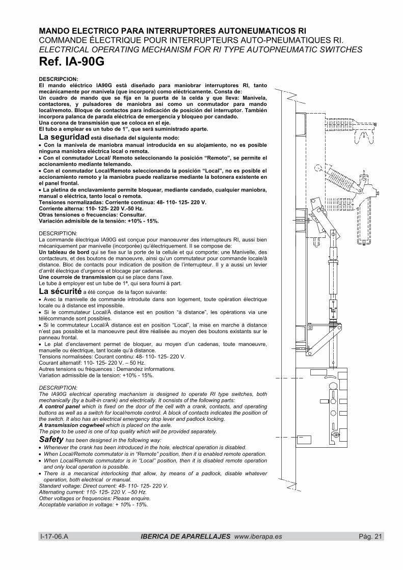
MANDO ELECTRICO PARA INTERRUPTORES AUTONEUMATICOS RI COMMANDE ÉLECTRIQUE POUR INTERRUPTEURS AUTO-PNEUMATIQUES RI. ELECTRICAL OPERATING MECHANISM FOR RI TYPE AUTOPNEUMATIC SWITCHES Ref. IA-90G DESCRIPCION: El mando eléctrico IA90G está diseñado para maniobrar interruptores RI, tanto mecánicamente por manivela (que incorpora) como eléctricamente. Consta de: Un cuadro de mando que se fija en la puerta de la celda y que lleva: Manivela, contactores, y pulsadores de maniobra así como un conmutador para mando local/remoto. Bloque de contactos para indicación de posición del interruptor. También incorpora palanca de parada eléctrica de emergencia y bloqueo por candado. Una corona de transmisión que se coloca en el eje. El tubo a emplear es un tubo de 1”, que será suministrado aparte. La seguridad está diseñada del siguiente modo: � Con la manivela de maniobra manual introducida en su alojamiento, no es posible ninguna maniobra eléctrica local o remota. � Con el conmutador Local/ Remoto seleccionando la posición “Remoto”, se permite el accionamiento mediante telemando. � Con el conmutador Local/Remoto seleccionando la posición “Local”, no es posible el accionamiento remoto y la maniobra puede realizarse mediante la botonera existente en el panel frontal. � La pletina de enclavamiento permite bloquear, mediante candado, cualquier maniobra, manual o eléctrica, tanto local o remota. Tensiones normalizadas: Corriente continua: 48- 110- 125- 220 V. Corriente alterna: 110- 125- 220 V.-50 Hz. Otras tensiones o frecuencias: Consultar. Variación admisible de la tensión: +10% - 15%.
DESCRIPTION: La commande électrique IA90G est conçue pour manoeuvrer des interrupteurs RI, aussi bien mécaniquement par manivelle (incorporée) qu’électriquement. II se compose de: Un tableau de bord qui se fixe sur la porte de la cellule et qui comporte: une Manivelle, des contacteurs, et des boutons de manoeuvre, ainsi qu’un commutateur pour commande locale/à distance. Bloc de contacts pour indication de position de l’interrupteur. II y a aussi un levier d’arrêt électrique d’urgence et blocage par cadenas. Une courroie de transmission qui se place dans l’axe. Le tube à employer est un tube de 1ª, qui sera fourni à part. La sécurité a été conçue de la façon suivante: � Avec la manivelle de commande introduite dans son logement, toute opération électrique locale ou à distance est impossible. � Si le commutateur Local/À distance est en position “à distance”, les opérations via une télécommande sont possibles. � Si le commutateur Local/À distance est en position “Local”, la mise en marche à distance n’est pas possible et la manoeuvre peut être réalisée au moyen des boutons existants sur le panneau frontal. � Le plat d’enclavement permet de bloquer, au moyen d’un cadenas, toute manoeuvre, manuelle ou électrique, tant locale qu’à distance. Tensions normalisées: Courant continu: 48- 110- 125- 220 V. Courant alternatif: 110- 125- 220 V. – 50 Hz. Autres tensions ou fréquences : Demandez informations. Variation admissible de la tension: +10% - 15%.
DESCRIPTION: The IA90G electrical operating machanism is designed to operate RI type switches, both mechanically (by a built-in crank) and electrically. It ocnsists of the following parts: A control panel which is fixed on the door of the cell with a crank, contacts, and operating buttons as well as a switch for local/remote control. A block of contacts indicates the position of the switch. It also has an electrical emergency stop lever and padlock locking. A transmission cogwheel which is placed on the axle. The pipe to be used is one of top quality which will be provided separately. Safety has been designed in the following way: � Whenever the crank has been introduced in the hole, electrical operation is disabled. � When Local/Remote commutator is in “Remote” position, then it is enabled remote operation. � When Local/Remote commutator is in “Local” position, then it is disabled remote operation
and only local operation is possible. � There is a mecanical interlocking that allow, by means of a padlock, disable whatever
operation, both electrical or manual. Standard voltage: Direct current: 48- 110- 125- 220 V. Alternating current: 110- 125- 220 V. –50 Hz. Other voltages or frequencies: Please enquire. Acceptable variation in voltage: + 10% - 15%.

I-17-06.A IBERICA DE APARELLAJES www.iberapa.es Pág. 22 I-17-06.A IBERICA DE APARELLAJES www:iberapa.es Pág. 24
MOTORIZACION DE INTERRUPTORES AUTONEUMATICOS TIPO RIF Y RID MOTORIZATION D’INTERRUPTEURS AUTO-PNEUMATIQUES TYPE RIF ET RID. MOTORISATION OF RIF AND RID TYPE AUTOPNEUMATIC SWITCHES
Los interruptores autoneumáticos tipo RIF (combinado interruptor fusible con o sin relés), pueden ser operados mediante mando eléctrico. El “kit” de motorización incluye las siguientes piezas que se indican en la figura: 1) Motor eléctrico. 2) Reductor. 3) Mecanismo de retención. 4) Contactos de señal fin de curso del
motor.5) Contactos de señal (salida cofre de
mando). 6) Cableado entre motor y contacto de
señal.
Les interrupteurs auto-pneumatiques type RIF (combiné interrupteur-fusible avec ou snas relais), peuvent être opérés au moyen d’une commande électrique. Le “kit” de motorisation comprend les pièces suivantes, voir aussi le schéma: 1) Moteur électrique 2) Réducteur 3) Mécanisme de rétention 4) Contacts de signal de fin de course du
moteur5) Contacts de signal (sortie boîte de
commande)6) Câblage entre moteur et contact de
signal.
The RIF type (combined switch-fuse with or without relays) autopneumatic switches, can be operated by means of an electrical operating mechanism. The motorisation kit includes the following parts, which are indicated in diagram: 1) Electrical motor 2) Reduction motor 3) Retention mechanism 4) Signal contacts of the end of the motor’s
course5) Signal contacts (output control box) 6) Wiring between engine and signal
contact
No están incluidos los pulsadores de accionamiento ni el cableado entre estos pulsadores y los contactos de señal. Este tipo de motorización no permite que el interruptor sea accionado manualmente mediante manivela.
Ne sont pas inclus les boutons de mise en marche ni le câblage entre ces boutons et les contacts de signal. Ce type de motorisation ne permet pas que l’interrupteur soit actionné manuellement par manivelle.
The activating buttons, wiring between these buttons, and signal contacts are not included. This type of motorisation does not allow the switch to be activated manually with a crank.
CARACTERISTICAS MANDO ELECTRICO / CARATERISTIQUES COMMANDE ELECTTRIQUE / CHARACTERISTICS OF ELECTRICAL OPERATING MECHANISM
Tensiones normales de alimentación (V). Tensions normales d’alimentation (V). Rated voltage (V).
c. continua / c. alterna c. continu / c. alternatif direct current / alternating current
48-110-220 110-220
Variación admisible de la tensión. Variation admisible de la tension. Acceptable variation in voltage.
+10%-15%
Potencia absorbida en el arranque / marcha normal. Puissance absorbée à la mise en marche / marche normale. Power absorbed during the starting operatin / normal work.
c. continua / c. alterna c. continu / c. alternatif direct current / alternating current
CONSULTAR CONSULTE
PLEASE ENQUIRE Tiempo para tensado del resorte con tensión nominal. Temps pour la tension du resort avec tension nominale. Time required to tauten spring with normal voltage.
6 a 15 s.

I-17-06.A IBERICA DE APARELLAJES www.iberapa.es Pág. 23 I-17-06.A IBERICA DE APARELLAJES www:iberapa.es Pág. 25
Ref. IA-35 Ref. IA-35/200 IA-35C
Ref. IA-35CABEZAL TETE HEADSTOCK
Seccionador interior accionado con mando Sectioneur intérieur actioné par commande Indoor disconnector operated by lever
MANDOS MECANICOS PARA SECCIONADORES E INTERRUPTORES DE INTERIOR COMMANDES MECANIQUES MANUELLES POUR DES SECTIONNEURS ET DES INTERRUPTEURS POUR L’INTERIEUR MANUALLY OPERATED CONTROL LEVERS FOR OPERATING DISCONNECTORS AND SWITCHES. INDOOR TYPES
Ref. IA-35: Mando salida anterior o delantera. Enclavamientos: Mediante clavija y candado. Empleo: Para accionamiento de seccionadores (IA-35) e interruptores de interior tipo IA-200 sc (IA-35 C) e interruptores IA-200 sc F/FR (IA-35/200). Para seccionadores 36KV 1250-2000 A usar el mando IA35/300 que emplea tubo 1” Ref. IA-35: Commande sortie antèrieur ou avant. Enclavements : Par goupille et cadenas. Emploi: Pour l’actionement de sectionneurs (IA-35) et d’interrupteurs d’interieur IA-200 sc (IA-35 C) et interrupteurs IA-200 sc F/FR (IA-35/200). Pour sectionneur 36KV 1250-1600 A il faut mettre IA35/300 avec tube 1” Ref. IA-35: Front-projecting of front-mounted lever. Locking device by pin and padlock. Use: For operating indoor disconnector (IA-35) and switches type IA-200 (IA-35 C) and for switches type IA-200 sc F/FR (IA-35/200). With disconnectors 36 KV 1250-200 A to use IA35/300 with tube 1”.
Ref. IA-40 Ref. IA-40/200 IA-40 C CABEZAL TETE HEADSTOCKRef. IA-40
Ref. IA-40: Mando salida posterior o traspanel. Enclavamientos: Mediante clavija y candado o cerradura tipo HERPE. Accesorios: Bloques de contactos auxiliares para circuitos de señalización. Empleo: Para accionamiento de seccionadores (IA-40) e interruptores de interior IA-200 sc (IA-40 C) y para interruptores IA-200 sc F/FR (IA-40/200). Para seccionadores de 36KV 1250-2000 A añadir a la referencia 1250 ( IA40/1250) y emplear tubo de 1”. Ref. IA-40: Commande sortie postérieure ou arrière-panneau. Enclavaments: Par goupille et cadenas ou serrure HERPE. Accessoires: Blocs de contacts auxiliaires pour circuits de signalisation. Emploi: Pour l’actionement de sectionneurs (IA-35) et d’interrupteurs d’intérieure IA-200 sc (IA-40 C) et interrupteurs IA-200 sc F/FR (IA-40/200). Pour sectionneurs 36 KV 1250-2000 A ajouter a la reference “1250” (L IA40/1250) et il faut metre tube 1”. Ref. IA-40: Rear-projection or through-panel lever. Locking devices: By pin and padlock of HERPE type Key. Acccessories: Auxiliary contact banks for singalling circuits. Use: For operating indoor disconnectors (IA-35) and switches IA-200 sc (IA-40 C) and switches IA-200 sc F/FR (IA-40/200). For disconnetctors 36 KV 1250-2000 A add in reference “1250” (IA-40/1250) ant to use tube 1”.
Seccionador interior accionado con mando Sectioneur intérieur actioné par commandeIndoor disconnector operated by lever
Abertura para

I-17-06.A IBERICA DE APARELLAJES www.iberapa.es Pág. 24 I-17-06.A IBERICA DE APARELLAJES www:iberapa.es Pág. 26
IA-40/200 Interruptor IA-200sc FR accionado con mando. IA-40/200 Interruptor IA-200sc FR actioné par commande. IA-40/200 Switch IA-200sc FR operated by operating mechanism.
Ref. IA-41 Ref. IA-41/200 IA-41C CABEZAL TETE HEADSTOCK Ref. IA-41
Cambio de dirección Changement de direction Change of direction
IA-40Interruptor IA-200 sc accionado con mando. IA-40Interruptor IA-200 sc actioné par commande. IA-40Switch IA-200 sc operated by operating mechanism.
Ref. IA-41: Mando salida posterior a traspanel. Enclavamientos: Mediante clavija y candado o cerradura tipo HERPE. Accesorios: Bloques de contactos auxiliares para circuitos de señalización. Empleo: Para accionamiento de seccionadores (IA-41) e interruptores de itnerior IA-200 sc (IA-41 C) o IA-200 sc F/FR (IA-41/200) con inclusión de rótula en la transmisión. Ref. IA-41: Commande sortie postérieure ou arrière panneau. Enclavements: Par goupille et cadenas ou serrure HERPE. Accessoires: Blocs de contacts auxiliaires pour circuits de signalisation. Emploi: Pour l’actionnement de sectionneurs et d’interrupteurs d’intèrieure, IA.200 sc (IA-41 C) ou IA-200 sc F/FR (IA-41/200), avec inclusion de rotule dans la transmission. Ref. IA-41: Rear-projection or throught-panel lever. Locking devices: By pin and padlock or HERPE tipe Key. Accessoires: Auxiliary contact banks for signalling circuits. Use: To operate indoor disconnectors (IA-41) and switches, IA-200 sc (IA-41 C) or IA-200 sc F/FR (IA-41/200), including ball and socket joints in transmission path.
Seccionador interior accionado con mando Sectionneur intèrieur actioné par commande Indoor disconnector operated by operating mechanism
I-17-06.A IBERICA DE APARELLAJES www.iberapa.es Pág. 25 I-17-06.A IBERICA DE APARELLAJES www:iberapa.es Pág. 27
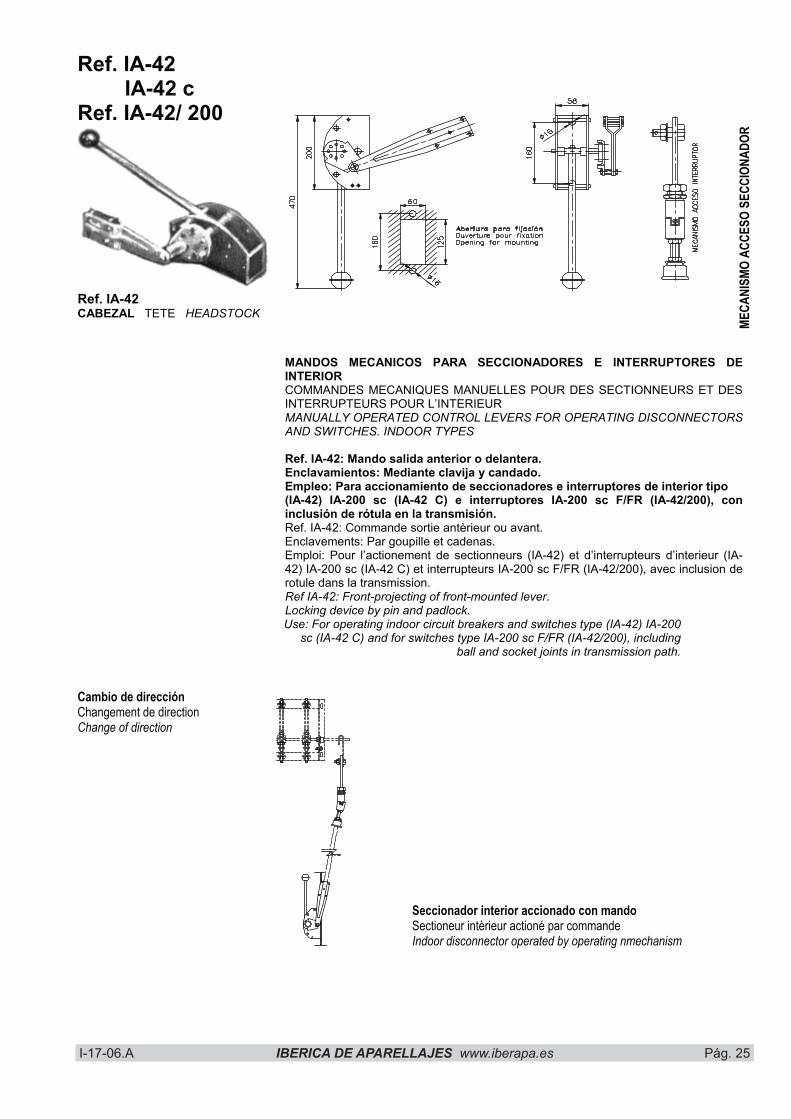
Ref. IA-42 IA-42 c Ref. IA-42/ 200
Ref. IA-42CABEZAL TETE HEADSTOCK
MECA
NISM
O AC
CESO
SEC
CION
ADOR
MANDOS MECANICOS PARA SECCIONADORES E INTERRUPTORES DE INTERIORCOMMANDES MECANIQUES MANUELLES POUR DES SECTIONNEURS ET DES INTERRUPTEURS POUR L’INTERIEUR MANUALLY OPERATED CONTROL LEVERS FOR OPERATING DISCONNECTORS AND SWITCHES. INDOOR TYPES
Ref. IA-42: Mando salida anterior o delantera. Enclavamientos: Mediante clavija y candado. Empleo: Para accionamiento de seccionadores e interruptores de interior tipo (IA-42) IA-200 sc (IA-42 C) e interruptores IA-200 sc F/FR (IA-42/200), con inclusión de rótula en la transmisión. Ref. IA-42: Commande sortie antèrieur ou avant. Enclavements: Par goupille et cadenas. Emploi: Pour l’actionement de sectionneurs (IA-42) et d’interrupteurs d’interieur (IA-42) IA-200 sc (IA-42 C) et interrupteurs IA-200 sc F/FR (IA-42/200), avec inclusion de rotule dans la transmission. Ref IA-42: Front-projecting of front-mounted lever. Locking device by pin and padlock. Use: For operating indoor circuit breakers and switches type (IA-42) IA-200
sc (IA-42 C) and for switches type IA-200 sc F/FR (IA-42/200), including ball and socket joints in transmission path.
Cambio de dirección Changement de direction Change of direction
Seccionador interior accionado con mando Sectioneur intèrieur actioné par commande Indoor disconnector operated by operating nmechanism

I-17-06.A IBERICA DE APARELLAJES www.iberapa.es Pág. 26 I-17-06.A IBERICA DE APARELLAJES www:iberapa.es Pág. 28
Ref. IA-43 PALANCA DE ACCIONAMIENTO EN “L”: Para accionamiento lateral de seccionadores e interruptores de interior.
LEVIER D’ACTIONNEMENT EN “L”: Pour l’actionnement latéral de sectionneurs et d’interrupteurs d’intérieur.
“L” SHAPED OPERATING LEVER: For lateral operation or indoor disconnectors and switches.
ACCESORIOS * ACCESSOIRES * ACCESSOIRES� Prolongaciones de eje. � Mecanismo acodado para cambio de dirección. � Tubo de transmisión. � Bloques de contacto para circuitos de señalización. � Cerraduras tipo HERPE, en IA-40 o IA-41; � Bobinas de enclavamiento en mando IA-40. � Prolongements d’axes. � Mecanisme coudé pour changement de direction. � Blocs de contacts pour circuits de signalisation. � Serrures type HERPE, dans la commande IA-40 ou IA-41.� Bobine d’enclavement dans la commande IA-40. � Shaft extenders. � Elbow element for change of direction. � Transmission pipe. � Contact banks signalling circuits. � HERPE type locksin IA-40 or IA-41. � Device coil in IA-40.
CABEZAL IA-40 EQUIPADO CON CERRADURAS HERPE TETE IA-40 EQUIPEE DE SERRURE TYPE HERPE HEADSTOCK IA-40 FITTED WITH HERPE TYPE LOCK
MECANISMO ACODADO (90º) MECANISME COUDE (90º) ELBOW MECHANISM (90º)
Seccion AB
I-17-06.A IBERICA DE APARELLAJES www.iberapa.es Pág. 27 I-17-06.A IBERICA DE APARELLAJES www:iberapa.es Pág. 29
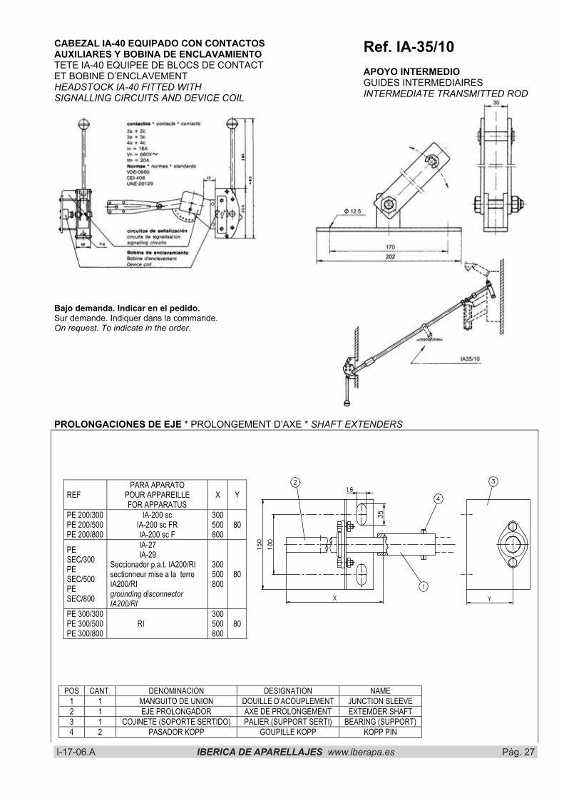
CABEZAL IA-40 EQUIPADO CON CONTACTOS AUXILIARES Y BOBINA DE ENCLAVAMIENTOTETE IA-40 EQUIPEE DE BLOCS DE CONTACT ET BOBINE D’ENCLAVEMENT HEADSTOCK IA-40 FITTED WITH SIGNALLING CIRCUITS AND DEVICE COIL
Bajo demanda. Indicar en el pedido. Sur demande. Indiquer dans la commande. On request. To indicate in the order.
Ref. IA-35/10 APOYO INTERMEDIO GUIDES INTERMEDIAIRES INTERMEDIATE TRANSMITTED ROD
PROLONGACIONES DE EJE * PROLONGEMENT D’AXE * SHAFT EXTENDERS
REFPARA APARATO
POUR APPAREILLE FOR APPARATUS
X Y
PE 200/300 PE 200/500 PE 200/800
IA-200 sc IA-200 sc FR IA-200 sc F
300500800
80
PESEC/300PESEC/500PESEC/800
IA-27 IA-29 Seccionador p.a.t. IA200/RI sectionneur mise a la terre IA200/RI grounding disconnector IA200/RI
300500800
80
PE 300/300 PE 300/500 PE 300/800
RI 300500800
80
POS CANT. DENOMINACION DESIGNATION NAME 1 1 MANGUITO DE UNION DOUILLE D’ACOUPLEMENT JUNCTION SLEEVE 2 1 EJE PROLONGADOR AXE DE PROLONGEMENT EXTEMDER SHAFT 3 1 COJINETE (SOPORTE SERTIDO) PALIER (SUPPORT SERTI) BEARING (SUPPORT) 4 2 PASADOR KOPP GOUPILLE KOPP KOPP PIN

I-17-06.A IBERICA DE APARELLAJES www.iberapa.es Pág. 28 I-17-06.A IBERICA DE APARELLAJES www:iberapa.es Pág. 30
Relés tipo RTE 4b Relais tipe RTE 4b Relays type RTE 4b
CARACTERISTICAS
ACCION DIFERIDA Intensidad de funcionamiento regulable ToleranciaLímites de retardo, seg.
1 a 1,6 In + 10% ver curvas
SOBREINTENSIDAD ADMISIBLE 0,2 segundos 1 segundo En permanencia
220 In 30 In 1,8 In
Tensión de aislamiento del borne superior Con relación a la masa de relé
2 kV
Consumo a In 5 VA. Peso Kg. 0,5 GAMA DE INTENSIDADES NOMINALES 0,4 – 0,64 – 1 – 1,6 – 2 – 3 – 4 – 5 – 7 – 10 – 15 20 – 25 – 30 – 40 – 50 – 60 – 80 – 100 – 125 A.
CARACTERISTIQUES
ACTION RETARDEE Intensité de fonctionnement regulable Tolerance Limite de retarde sec.
1 à 1,6 In + 10% voir courbes
SURINTENSITE ADMISSIBLE 0,2 sec. 1 seconde En permanence
220 In 30 In 1,8 In
Tension d’isolement de la borne superieur Par rappor â la masse du relais
2 Kv
Consommation â In 5 VA. Poidos Kg. 0,5 GAMME DES INTENSITES NOMINALES 0,4 – 0,64 – 1 – 1,6 – 2 – 3 – 4 – 5 – 7 – 10 – 15 20 – 25 – 30 – 40 – 50 – 60 – 80 – 100 – 125 A.
CHARACTERISTICS
DELAYED ACTION Regulable operating-current Tolerance Delay time limit sec.
1 to 1,6 In + 10%see curves
ADMISSIBLE OVERCURRENT 0,2 sec. 1 second Permanently
220 In 30 In 1,8 In
Insulation voltage of the top contact Related to the relays mass
2 KV
Consumption 5 VA Weight Kg. 0,5 RANGE OF RATED CURRENTS 0,4 – 0,64 – 1 – 1,6 – 2 – 3 – 3 – 4 – 5 – 7 – 10 – 15 – 20 – 25 – 30 – 40 – 50 – 60 – 80 – 100 – 125 A.
Los relés tipo RTE 4b son de ación diferida a tiempo inverso. Previstos para equipar los interruptores auto-neumáticos tipo RIF hasta 36 kV, están alimentados directamente por la corriente que atraviesa el interruptor, permitiendo realizar una protección económica y segura de trans-formadores, motores, líneas, etc. Provocan mecánicamente, la apertura del interruptor sobre el que van montados, por intermedio de una timonería aislante.
Les relais du type RTE 4b sont d’action retardée à temps inverse. Prévus pour équiper les interrupteurs à soufflage autopneumatique type RIF jusqu’à 36 kV, ils sont alimentés directement par la courant traversant l’interruteur en permettant de réaliser une protection economique el sûre des tranfor-mateurs, moteurs, lignes, etc. Ils provoquent mecaniquement au moyen d’une tringlerie isolante le declenchement de l’inte-rrupteur sus lequel ils sont installés.
The relays type RTE 4b are inverse-timed dela-yed-action relays. Conceived for fitting the autopneumatic switches Type RIF until 36 kV, they are directly fed by the current running through the switch, what allows a economic and safe protection of transformers, motors, lines, etc. They provoke mechanically by means of an insulating device the openning of the switch, they are mounted on.
I-17-06.A IBERICA DE APARELLAJES www.iberapa.es Pág. 29 I-17-06.A IBERICA DE APARELLAJES www:iberapa.es Pág. 31
Tiem
po d
e des
enga
nche
en se
gund
os
Temp
s de d
éclen
chem
ent e
n sec
onde
s Re
lease
– tim
e in
seco
nds
INTENSIDAD (Multiplos de In) – COURANT - CURRENT
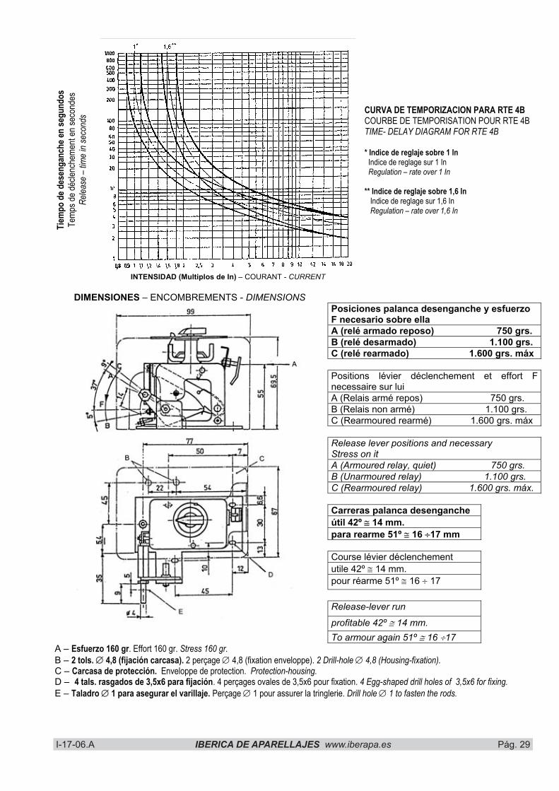
CURVA DE TEMPORIZACION PARA RTE 4B COURBE DE TEMPORISATION POUR RTE 4B TIME- DELAY DIAGRAM FOR RTE 4B
* Indice de reglaje sobre 1 In Indice de reglage sur 1 In Regulation – rate over 1 In
** Indice de reglaje sobre 1,6 In Indice de reglage sur 1,6 In
Regulation – rate over 1,6 In
DIMENSIONES – ENCOMBREMENTS - DIMENSIONSPosiciones palanca desenganche y esfuerzo F necesario sobre ella A (relé armado reposo) 750 grs. B (relé desarmado) 1.100 grs. C (relé rearmado) 1.600 grs. máx
Positions lévier déclenchement et effort F necessaire sur lui A (Relais armé repos) 750 grs. B (Relais non armé) 1.100 grs. C (Rearmoured rearmé) 1.600 grs. máx
Release lever positions and necessary Stress on itA (Armoured relay, quiet) 750 grs. B (Unarmoured relay) 1.100 grs. C (Rearmoured relay) 1.600 grs. máx.
Carreras palanca desenganche útil 42º � 14 mm. para rearme 51º � 16 �17 mm
Course lévier déclenchement utile 42º � 14 mm. pour réarme 51º � 16 � 17
Release-lever run
profitable 42º � 14 mm. To armour again 51º � 16 �17
A – Esfuerzo 160 gr. Effort 160 gr. Stress 160 gr.B – 2 tols. � 4,8 (fijación carcasa). 2 perçage � 4,8 (fixation enveloppe). 2 Drill-hole � 4,8 (Housing-fixation).C – Carcasa de protección. Enveloppe de protection. Protection-housing.D – 4 tals. rasgados de 3,5x6 para fijación. 4 perçages ovales de 3,5x6 pour fixation. 4 Egg-shaped drill holes of 3,5x6 for fixing.E – Taladro � 1 para asegurar el varillaje. Perçage � 1 pour assurer la tringlerie. Drill hole � 1 to fasten the rods.