ap1000 european 21. construction verification process ... p… · ap1000 european 21. construction...
TRANSCRIPT

AP1000 European 21. Construction Verification Process Design Control Document
EPS-GW-GL-700 21-323 Revision 1
2.5 Instrumentation and Control Systems
2.5.1 Diverse Actuation System
Design Description
The diverse actuation system (DAS) initiates reactor trip, actuates selected functions, and provides plant information to the operator.
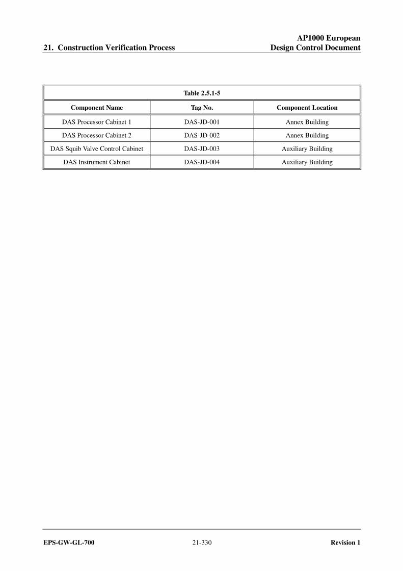
The component locations of the DAS are as shown in Table 2.5.1-5.
1. The functional arrangement of the DAS is as described in the Design Description of this Section 2.5.1.
2. The DAS provides the following nonsafety-related functions:
a) The DAS provides an automatic reactor trip on low wide-range steam generator water level or on low pressurizer water level separate from the PMS.
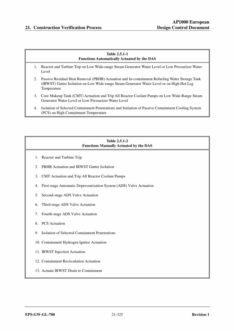
b) The DAS provides automatic actuation of selected functions, as identified in Table 2.5.1-1, separate from the PMS.
c) The DAS provides manual initiation of reactor trip and selected functions, as identified in Table 2.5.1-2, separate from the PMS. These manual initiation functions are implemented in a manner that bypasses the control room multiplexers, if any; the PMS cabinets; and the signal processing equipment of the DAS.
d) The DAS provides main control room (MCR) displays of selected plant parameters, as identified in Table 2.5.1-3, separate from the PMS.
3. The DAS has the following features:
a) The signal processing hardware of the DAS uses input modules, output modules, and microprocessor or special purpose logic processor boards that are different than those used in the PMS.
b) The display hardware of the DAS uses a different display device than that used in the PMS.
c) Any operating systems or programming languages used by DAS are different than those used in the PMS.
d) The DAS has electrical surge withstand capability (SWC), and can withstand the electromagnetic
interference (EMI), radio frequency (RFI), and electrostatic discharge (ESD) conditions that exist where the DAS equipment is located in the plant.
e) The sensors identified on Table 2.5.1-3 are used for DAS input and are separate from those being used by the PMS and plant control system.
f) The DAS is powered by non-Class 1E uninterruptible power supplies that are independent and
separate from the power supplies which power the PMS.

AP1000 European 21. Construction Verification Process Design Control Document
EPS-GW-GL-700 21-324 Revision 1
g) The DAS signal processing cabinets are provided with the capability for channel testing without actuating the controlled components.
h) The DAS equipment can withstand the room ambient temperature and humidity conditions that will exist at the plant locations in which the DAS equipment is installed at the times for which the DAS is designed to be operational.
4. The DAS hardware and any software are developed using a planned design process which provides for specific design documentation and reviews during the following life cycle stages:
a) Development phase for hardware and any software b) System test phase c) Installation phase
The planned design process also provides for the use of commercial off-the-shelf hardware and software.
Inspections, Tests, Analyses, and Acceptance Criteria
Table 2.5.1-4 specifies the inspections, tests, analyses, and associated acceptance criteria for the DAS.
AP1000 European 21. Construction Verification Process Design Control Document
EPS-GW-GL-700 21-325 Revision 1
Table 2.5.1-1 Functions Automatically Actuated by the DAS
1. Reactor and Turbine Trip on Low Wide-range Steam Generator Water Level or Low Pressurizer Water Level
2. Passive Residual Heat Removal (PRHR) Actuation and In-containment Refueling Water Storage Tank (IRWST) Gutter Isolation on Low Wide-range Steam Generator Water Level or on High Hot Leg Temperature
3. Core Makeup Tank (CMT) Actuation and Trip All Reactor Coolant Pumps on Low Wide-Range Steam Generator Water Level or Low Pressurizer Water Level
4. Isolation of Selected Containment Penetrations and Initiation of Passive Containment Cooling System (PCS) on High Containment Temperature
Table 2.5.1-2 Functions Manually Actuated by the DAS
1. Reactor and Turbine Trip
2. PRHR Actuation and IRWST Gutter Isolation
3. CMT Actuation and Trip All Reactor Coolant Pumps
4. First-stage Automatic Depressurization System (ADS) Valve Actuation
5. Second-stage ADS Valve Actuation
6. Third-stage ADS Valve Actuation
7. Fourth-stage ADS Valve Actuation
8. PCS Actuation
9. Isolation of Selected Containment Penetrations
10. Containment Hydrogen Ignitor Actuation
11. IRWST Injection Actuation
12. Containment Recirculation Actuation
13. Actuate IRWST Drain to Containment

AP1000 European 21. Construction Verification Process Design Control Document
EPS-GW-GL-700 21-326 Revision 1
Table 2.5.1-3 DAS Sensors and Displays
Equipment Name Tag Number
Reactor Coolant System (RCS) Hot Leg Temperature RCS-300A
RCS Hot Leg Temperature RCS-300B
Steam Generator 1 Wide-range Level SGS-044
Steam Generator 1 Wide-range Level SGS-045
Steam Generator 2 Wide-range Level SGS-046
Steam Generator 2 Wide-range Level SGS-047
Pressurizer Water Level RCS-305A
Pressurizer Water Level RCS-305B
Containment Temperature VCS-053A
Containment Temperature VCS-053B
Core Exit Temperature IIS-009
Core Exit Temperature IIS-013
Core Exit Temperature IIS-030
Core Exit Temperature IIS-034

AP1000 European 21. Construction Verification Process Design Control Document
EPS-GW-GL-700 21-327 Revision 1
Table 2.5.1-4 Inspections, Tests, Analyses, and Acceptance Criteria
Design Commitment Inspections, Tests, Analyses Acceptance Criteria
1. The functional arrangement of the DAS is as described in the Design Description of this Section 2.5.1.
Inspection of the as-built system will be performed.
The as-built DAS conforms with the functional arrangement as described in the Design Description of this Section 2.5.1.
2.a) The DAS provides an automatic reactor trip on low wide-range steam generator water level or on low pressurizer water level separate from the PMS.
Electrical power to the PMS equipment will be disconnected and an operational test of the as-built DAS will be performed using real or simulated test signals.
The field breakers of the control rod motor-generator sets open after the test signal reaches the specified limit.
2.b) The DAS provides automatic actuation of selected functions, as identified in Table 2.5.1-1, separate from the PMS.
Electrical power to the PMS equipment will be disconnected and an operational test of the as-built DAS will be performed using real or simulated test signals.
Appropriate DAS output signals are generated after the test signal reaches the specified limit.
2.c) The DAS provides manual initiation of reactor trip, and selected functions, as identified in Table 2.5.1-2, separate from the PMS. These manual initiation functions are implemented in a manner that bypasses the control room multiplexers, if any; the PMS cabinets; and the signal processing equipment of the DAS.
Electrical power to the control room multiplexers, if any, and PMS equipment will be disconnected and the outputs from the DAS signal processing equipment will be disabled. While in this configuration, an operational test of the as-built system will be performed using the DAS manual actuation controls.
i) The field breakers of the control rod motor-generator sets open after reactor and turbine trip manual initiation controls are actuated.
ii) DAS output signals are generated for the selected functions, as identified in Table 2.5.1-2, after manual initiation controls are actuated.
2.d) The DAS provides MCR displays of selected plant parameters, as identified in Table 2.5.1-3, separate from the PMS.
Electrical power to the PMS equipment will be disconnected and inspection will be performed for retrievability of the selected plant parameters in the MCR.
The selected plant parameters can be retrieved in the MCR.

AP1000 European 21. Construction Verification Process Design Control Document
EPS-GW-GL-700 21-328 Revision 1
Table 2.5.1-4 (cont.) Inspections, Tests, Analyses, and Acceptance Criteria
Design Commitment Inspections, Tests, Analyses Acceptance Criteria
3.a) The signal processing hardware of the DAS uses input modules, output modules, and microprocessor or special purpose logic processor boards that are different than those used in the PMS.
Inspection of the as-built DAS and PMS signal processing hardware will be performed.
The DAS signal processing equipment uses input modules, output modules, and micro-processor or special purpose logic processor boards that are different than those used in the PMS. The difference may be a different design, use of different component types, or different manufacturers.
3.b) The display hardware of the DAS uses a different display device than that used in the PMS.
Inspection of the as-built DAS and PMS display hardware will be performed.
The DAS display hardware is different than the display hardware used in the PMS. The difference may be a different design, use of different component types, or different manufacturers.
3.c) Any operating systems or programming languages used by DAS are different than those used in the PMS.
Inspection of the DAS and PMS design documentation will be performed.
Any DAS operating systems and programming languages are different than those used in the PMS.
3.d) The DAS has electrical surge withstand capability (SWC), and can withstand the electromagnetic interference (EMI), radio frequency (RFI), and electrostatic discharge (ESD) conditions that exist where the DAS equipment is located in the plant.
Type tests, analyses, or a combination of type tests and analyses will be performed on the equipment.
A report exists and concludes that the DAS equipment can withstand the SWC, EMI, RFI and ESD conditions that exist where the DAS equipment is located in the plant.
3.e) The sensors identified on Table 2.5.1-3 are used for DAS input and are separate from those being used by the PMS and plant control system.
Inspection of the as-built system will be performed.
The sensors identified on Table 2.5.1-3 are used by DAS and are separate from those being used by the PMS and plant control system.
3.f) The DAS is powered by non-Class 1E uninterruptible power supplies that are independent and separate from the power supplies which power the PMS.
Electrical power to the PMS equipment will be disconnected. While in this configuration, a test will be performed by providing simulated test signals in the non-Class 1E uninterruptible power supplies.
A simulated test signal exists at the DAS equipment when the assigned non-Class 1E uninterruptible power supply is provided the test signal.

AP1000 European 21. Construction Verification Process Design Control Document
EPS-GW-GL-700 21-329 Revision 1
Table 2.5.1-4 (cont.) Inspections, Tests, Analyses, and Acceptance Criteria
Design Commitment Inspections, Tests, Analyses Acceptance Criteria
3.g) The DAS signal processing cabinets are provided with the capability for channel testing without actuating the controlled components.
Channel tests will be performed on the as built system.
The capability exists for testing individual DAS channels without propagating an actuation signal to a DAS controlled component.
3.h) The DAS equipment can withstand the room ambient temperature and humidity conditions that will exist at the plant locations in which the DAS equipment is installed at the times for which the DAS is designed to be operational.
Type tests, analyses, or a combination of type tests and analyses will be performed on the equipment.
A report exists and concludes that the DAS equipment can withstand the room ambient temperature and humidity conditions that will exist at the plant locations in which the DAS equipment is installed at the times for which the DAS is designed to be operational.
4. The DAS hardware and any software are developed using a planned design process which provides for specific design documentation and reviews during the following life cycle stages:
a) Development phase for hardware and any software
b) System test phase
c) Installation phase
The planned design process also provides for the use of commercial off-the-shelf hardware and software.
Inspection will be performed of the process used to design the hardware and any software.
A report exists and concludes that the process defines the organizational responsibilities, activities, and configuration management controls for the following:
a) Documentation and review of hardware and any software.
b) Performance of tests and the documentation of test results during the system test phase.
c) Performance of tests and inspections during the installation phase.
The process also defines requirements for the use of commercial off-the-shelf hardware and software.
AP1000 European 21. Construction Verification Process Design Control Document
EPS-GW-GL-700 21-330 Revision 1
Table 2.5.1-5
Component Name Tag No. Component Location
DAS Processor Cabinet 1 DAS-JD-001 Annex Building
DAS Processor Cabinet 2 DAS-JD-002 Annex Building
DAS Squib Valve Control Cabinet DAS-JD-003 Auxiliary Building
DAS Instrument Cabinet DAS-JD-004 Auxiliary Building
AP1000 European 21. Construction Verification Process Design Control Document
EPS-GW-GL-700 21-331 Revision 1
2.5.2 Protection and Safety Monitoring System
Design Description
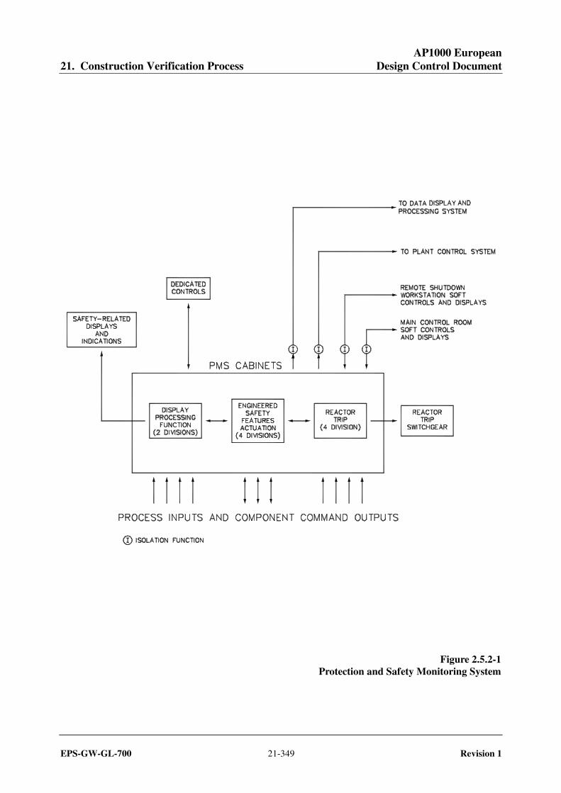
The protection and safety monitoring system (PMS) initiates reactor trip and actuation of engineered safety features in response to plant conditions monitored by process instrumentation and provides safety-related displays. The PMS has the equipment identified in Table 2.5.2-1. The PMS has four divisions of Reactor Trip and Engineered Safety Features Actuation, and two divisions of safety-related post-accident parameter displays. The functional arrangement of the PMS is depicted in Figure 2.5.2-1 and the component locations of the PMS are as shown in Table 2.5.2-9.
1. The functional arrangement of the PMS is as described in the Design Description of this Section 2.5.2.
2. The seismic Category I equipment, identified in Table 2.5.2-1, can withstand seismic design basis loads without loss of safety function.
3. The Class 1E equipment, identified in Table 2.5.2-1, has electrical surge withstand capability (SWC), and can withstand the electromagnetic interference (EMI), radio frequency interference (RFI), and electrostatic discharge (ESD) conditions that would exist before, during, and following a design basis accident without loss of safety function for the time required to perform the safety function.
4. The Class 1E equipment, identified in Table 2.5.2-1, can withstand the room ambient temperature, humidity, pressure, and mechanical vibration conditions that would exist before, during, and following a design basis accident without loss of safety function for the time required to perform the safety function.
5. a) The Class 1E equipment, identified in Table 2.5.2-1, is powered from its respective Class 1E division.
b) Separation is provided between PMS Class 1E divisions, and between Class 1E divisions and non-Class 1E cable.
6. The PMS provides the following safety-related functions:
a) The PMS initiates an automatic reactor trip, as identified in Table 2.5.2-2, when plant process signals reach specified limits.
b) The PMS initiates automatic actuation of engineered safety features, as identified in Table 2.5.2-3, when plant process signals reach specified limits.
c) The PMS provides manual initiation of reactor trip and selected engineered safety features as identified in Table 2.5.2-4.
7. The PMS provides the following nonsafety-related functions:
a) The PMS provides process signals to the plant control system (PLS) through isolation devices.

AP1000 European 21. Construction Verification Process Design Control Document
EPS-GW-GL-700 21-332 Revision 1
b) The PMS provides process signals to the data display and processing system (DDS) through isolation devices.
c) Data communication between safety and nonsafety systems does not inhibit the performance of the safety function.
d) The PMS ensures that the automatic safety function and the Class 1E manual controls both have priority over the non-Class 1E soft controls.
8. The PMS, in conjunction with the operator workstations, provides the following functions:
a) The PMS provides for the minimum inventory of displays, visual alerts, and fixed position controls, as identified in Table 2.5.2-5. The plant parameters listed with a "Yes" in the "Display" column and visual alerts listed with a "Yes" in the "Alert" column can be retrieved in the main control room (MCR). The fixed position controls listed with a "Yes" in the "Control" column are provided in the MCR.
b) The PMS provides for the transfer of control capability from the MCR to the remote shutdown workstation (RSW) using multiple transfer switches. Each individual transfer switch is associated with only a single safety-related group or with nonsafety-related control capability.
c) Displays of the open/closed status of the reactor trip breakers can be retrieved in the MCR.
9. a) The PMS automatically removes blocks of reactor trip and engineered safety features actuation when the plant approaches conditions for which the associated function is designed to provide protection. These blocks are identified in Table 2.5.2-6.
b) The PMS two-out-of-four initiation logic reverts to a two-out-of-three coincidence logic if one of the four channels is bypassed. All bypassed channels are alarmed in the MCR.
c) The PMS does not allow simultaneous bypass of two redundant channels.
d) The PMS provides the interlock functions identified in Table 2.5.2-7.
10. Setpoints are determined using a methodology which accounts for loop inaccuracies, response testing, and maintenance or replacement of instrumentation.
11. The PMS hardware and software is developed using a planned design process which provides for specific design documentation and reviews during the following life cycle stages: a) Hardware and software development phase, consisting of hardware and software design and
implementation
b) System integration and test phase
c) Installation phase
AP1000 European 21. Construction Verification Process Design Control Document
EPS-GW-GL-700 21-333 Revision 1
12. The PMS software is designed, tested, installed, and maintained using a process which incorporates a graded approach according to the relative importance of the software to safety and specifies requirements for:
a) Software management including documentation requirements, standards, review requirements, and procedures for problem reporting and corrective action.
b) Software configuration management including historical records of software and control of software changes.
c) Verification and validation including requirements for reviewer independence.
13. The use of commercial grade hardware and software items in the PMS is accomplished through a process that specifies requirements for:
a) Review of supplier design control, configuration management, problem reporting, and change control.
b) Review of product performance.
c) Receipt acceptance of the commercial grade item.
d) Final acceptance based on equipment qualification and software validation in the integrated system.
Inspections, Tests, Analyses, and Acceptance Criteria
Table 2.5.2-8 specifies the inspections, tests, analyses, and associated acceptance criteria for the PMS.

AP1000 European 21. Construction Verification Process Design Control Document
EPS-GW-GL-700 21-334 Revision 1
Table 2.5.2-1 PMS Equipment Name and Classification
Equipment Name Seismic Cat. I Class 1E Qual. for
Harsh Envir.
PMS Cabinets, Division A Yes Yes No
PMS Cabinets, Division B Yes Yes No
PMS Cabinets, Division C Yes Yes No
PMS Cabinets, Division D Yes Yes No
Reactor Trip Switchgear, Division A Yes Yes No
Reactor Trip Switchgear, Division B Yes Yes No
Reactor Trip Switchgear, Division C Yes Yes No
Reactor Trip Switchgear, Division D Yes Yes No
MCR/RSW Transfer Panels Yes Yes No
MCR Safety-related Display, Division B Yes Yes No
MCR Safety-related Display, Division C Yes Yes No
MCR Safety-related Controls Yes Yes No

AP1000 European 21. Construction Verification Process Design Control Document
EPS-GW-GL-700 21-335 Revision 1
Table 2.5.2-2 PMS Automatic Reactor Trips
Source Range High Neutron Flux Reactor Trip Intermediate Range High Neutron Flux Reactor Trip Power Range High Neutron Flux (Low Setpoint) Trip Power Range High Neutron Flux (High Setpoint) Trip Power Range High Positive Flux Rate Trip Reactor Coolant Pump High Bearing Water Temperature Trip Overtemperature Delta-T Trip Overpower Delta-T Trip Pressurizer Low Pressure Trip Pressurizer High Pressure Trip Pressurizer High Water Level Trip Low Reactor Coolant Flow Trip Low Reactor Coolant Pump Speed Trip Low Steam Generator Water Level Trip High-2 Steam Generator Water Level Trip Automatic or Manual Safeguards Actuation Trip Automatic or Manual Depressurization System Actuation Trip Automatic or Manual Core Makeup Tank (CMT) Injection Trip

AP1000 European 21. Construction Verification Process Design Control Document
EPS-GW-GL-700 21-336 Revision 1
Table 2.5.2-3 PMS Automatically Actuated Engineered Safety Features
Safeguards Actuation Containment Isolation Automatic Depressurization System (ADS) Actuation Main Feedwater Isolation Reactor Coolant Pump Trip CMT Injection Turbine Trip (Isolated signal to nonsafety equipment) Steam Line Isolation Steam Generator Relief Isolation Steam Generator Blowdown Isolation Passive Containment Cooling Actuation Startup Feedwater Isolation Passive Residual Heat Removal (PRHR) Heat Exchanger Alignment Block of Boron Dilution Chemical and Volume Control System (CVS) Makeup Line Isolation Steam Dump Block (Isolated signal to nonsafety equipment) MCR Isolation and Air Supply Initiation Auxiliary Spray and Letdown Purification Line Isolation Containment Air Filtration System Isolation Normal Residual Heat Removal Isolation Refueling Cavity Isolation In-Containment Refueling Water Storage Tank (IRWST) Injection IRWST Containment Recirculation CVS Letdown Isolation Pressurizer Heater Block (Isolated signal to nonsafety equipment)

AP1000 European 21. Construction Verification Process Design Control Document
EPS-GW-GL-700 21-337 Revision 1
Table 2.5.2-4 PMS Manually Actuated Functions
Reactor Trip Safeguards Actuation Containment Isolation Depressurization System Stages 1, 2, and 3 Actuation Depressurization System Stage 4 Actuation Feedwater Isolation Core Makeup Tank Injection Actuation Steam Line Isolation Passive Containment Cooling Actuation Passive Residual Heat Removal Heat Exchanger Alignment IRWST Injection Containment Recirculation Actuation Control Room Isolation and Air Supply Initiation Steam Generator Relief Isolation Chemical and Volume Control System Isolation Normal Residual Heat Removal System Isolation
AP1000 European 21. Construction Verification Process Design Control Document
EPS-GW-GL-700 21-338 Revision 1
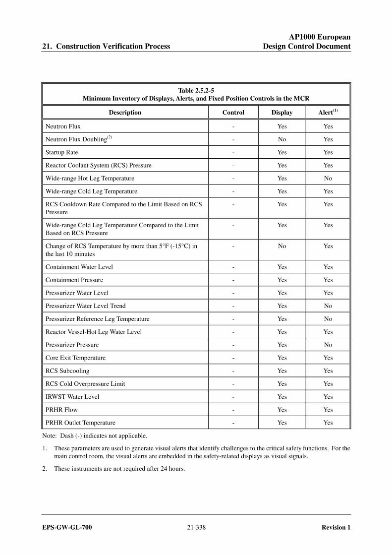
Table 2.5.2-5 Minimum Inventory of Displays, Alerts, and Fixed Position Controls in the MCR
Description Control Display Alert(1)
Neutron Flux - Yes Yes
Neutron Flux Doubling(2) - No Yes
Startup Rate - Yes Yes
Reactor Coolant System (RCS) Pressure - Yes Yes
Wide-range Hot Leg Temperature - Yes No
Wide-range Cold Leg Temperature - Yes Yes
RCS Cooldown Rate Compared to the Limit Based on RCS Pressure
- Yes Yes
Wide-range Cold Leg Temperature Compared to the Limit Based on RCS Pressure
- Yes Yes
Change of RCS Temperature by more than 5°F (-15°C) in the last 10 minutes
- No Yes
Containment Water Level - Yes Yes
Containment Pressure - Yes Yes
Pressurizer Water Level - Yes Yes
Pressurizer Water Level Trend - Yes No
Pressurizer Reference Leg Temperature - Yes No
Reactor Vessel-Hot Leg Water Level - Yes Yes
Pressurizer Pressure - Yes No
Core Exit Temperature - Yes Yes
RCS Subcooling - Yes Yes
RCS Cold Overpressure Limit - Yes Yes
IRWST Water Level - Yes Yes
PRHR Flow - Yes Yes
PRHR Outlet Temperature - Yes Yes
Note: Dash (-) indicates not applicable.
1. These parameters are used to generate visual alerts that identify challenges to the critical safety functions. For the main control room, the visual alerts are embedded in the safety-related displays as visual signals.
2. These instruments are not required after 24 hours.
AP1000 European 21. Construction Verification Process Design Control Document
EPS-GW-GL-700 21-339 Revision 1
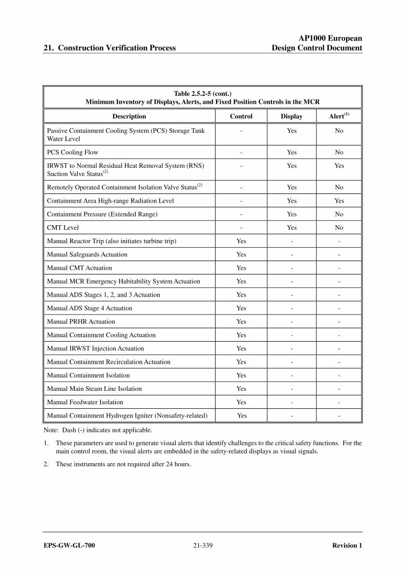
Table 2.5.2-5 (cont.) Minimum Inventory of Displays, Alerts, and Fixed Position Controls in the MCR
Description Control Display Alert(1)
Passive Containment Cooling System (PCS) Storage Tank Water Level
- Yes No
PCS Cooling Flow - Yes No
IRWST to Normal Residual Heat Removal System (RNS) Suction Valve Status(2)
- Yes Yes
Remotely Operated Containment Isolation Valve Status(2) - Yes No
Containment Area High-range Radiation Level - Yes Yes
Containment Pressure (Extended Range) - Yes No
CMT Level - Yes No
Manual Reactor Trip (also initiates turbine trip) Yes - -
Manual Safeguards Actuation Yes - -
Manual CMT Actuation Yes - -
Manual MCR Emergency Habitability System Actuation Yes - -
Manual ADS Stages 1, 2, and 3 Actuation Yes - -
Manual ADS Stage 4 Actuation Yes - -
Manual PRHR Actuation Yes - -
Manual Containment Cooling Actuation Yes - -
Manual IRWST Injection Actuation Yes - -
Manual Containment Recirculation Actuation Yes - -
Manual Containment Isolation Yes - -
Manual Main Steam Line Isolation Yes - -
Manual Feedwater Isolation Yes - -
Manual Containment Hydrogen Igniter (Nonsafety-related) Yes - -
Note: Dash (-) indicates not applicable.
1. These parameters are used to generate visual alerts that identify challenges to the critical safety functions. For the main control room, the visual alerts are embedded in the safety-related displays as visual signals.
2. These instruments are not required after 24 hours.
AP1000 European 21. Construction Verification Process Design Control Document
EPS-GW-GL-700 21-340 Revision 1
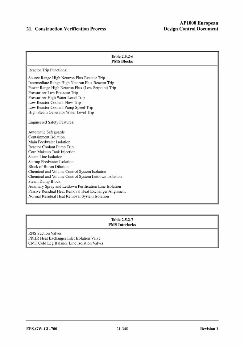
Table 2.5.2-6 PMS Blocks
Reactor Trip Functions:
Source Range High Neutron Flux Reactor Trip Intermediate Range High Neutron Flux Reactor Trip Power Range High Neutron Flux (Low Setpoint) Trip Pressurizer Low Pressure Trip Pressurizer High Water Level Trip Low Reactor Coolant Flow Trip Low Reactor Coolant Pump Speed Trip High Steam Generator Water Level Trip Engineered Safety Features: Automatic Safeguards Containment Isolation Main Feedwater Isolation Reactor Coolant Pump Trip Core Makeup Tank Injection Steam Line Isolation Startup Feedwater Isolation Block of Boron Dilution Chemical and Volume Control System Isolation Chemical and Volume Control System Letdown Isolation Steam Dump Block Auxiliary Spray and Letdown Purification Line Isolation Passive Residual Heat Removal Heat Exchanger Alignment Normal Residual Heat Removal System Isolation
Table 2.5.2-7 PMS Interlocks
RNS Suction Valves PRHR Heat Exchanger Inlet Isolation Valve CMT Cold Leg Balance Line Isolation Valves
AP1000 European 21. Construction Verification Process Design Control Document
EPS-GW-GL-700 21-341 Revision 1
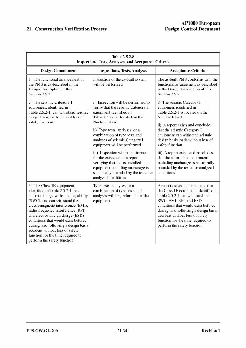
Table 2.5.2-8 Inspections, Tests, Analyses, and Acceptance Criteria
Design Commitment Inspections, Tests, Analyses Acceptance Criteria
1. The functional arrangement of the PMS is as described in the Design Description of this Section 2.5.2.
Inspection of the as-built system will be performed.
The as-built PMS conforms with the functional arrangement as described in the Design Description of this Section 2.5.2.
2. The seismic Category I equipment, identified in Table 2.5.2-1, can withstand seismic design basis loads without loss of safety function.
i) Inspection will be performed to verify that the seismic Category I equipment identified in Table 2.5.2-1 is located on the Nuclear Island.
ii) Type tests, analyses, or a combination of type tests and analyses of seismic Category I equipment will be performed.
iii) Inspection will be performed for the existence of a report verifying that the as-installed equipment including anchorage is seismically bounded by the tested or analyzed conditions.
i) The seismic Category I equipment identified in Table 2.5.2-1 is located on the Nuclear Island.
ii) A report exists and concludes that the seismic Category I equipment can withstand seismic design basis loads without loss of safety function.
iii) A report exists and concludes that the as-installed equipment including anchorage is seismically bounded by the tested or analyzed conditions.
3. The Class 1E equipment, identified in Table 2.5.2-1, has electrical surge withstand capability (SWC), and can withstand the electromagnetic interference (EMI), radio frequency interference (RFI), and electrostatic discharge (ESD) conditions that would exist before, during, and following a design basis accident without loss of safety function for the time required to perform the safety function.
Type tests, analyses, or a combination of type tests and analyses will be performed on the equipment.
A report exists and concludes that the Class 1E equipment identified in Table 2.5.2-1 can withstand the SWC, EMI, RFI, and ESD conditions that would exist before, during, and following a design basis accident without loss of safety function for the time required to perform the safety function.

AP1000 European 21. Construction Verification Process Design Control Document
EPS-GW-GL-700 21-342 Revision 1
Table 2.5.2-8 (cont.) Inspections, Tests, Analyses, and Acceptance Criteria
Design Commitment Inspections, Tests, Analyses Acceptance Criteria
4. The Class 1E equipment, identified in Table 2.5.2-1, can withstand the room ambient temperature, humidity, pressure, and mechanical vibration conditions that would exist before, during, and following a design basis accident without loss of safety function for the time required to perform the safety function.
Type tests, analyses, or a combination of type tests and analyses will be performed on the Class 1E equipment identified in Table 2.5.2-1.
A report exists and concludes that the Class 1E equipment identified in Table 2.5.2-1 can withstand the room ambient temperature, humidity, pressure, and mechanical vibration conditions that would exist before, during, and following a design basis accident without loss of safety function for the time required to perform the safety function.
5.a) The Class 1E equipment, identified in Table 2.5.2-1, is powered from its respective Class 1E division.
Tests will be performed by providing a simulated test signal in each Class 1E division.
A simulated test signal exists at the Class 1E equipment identified in Table 2.5.2-1 when the assigned Class 1E division is provided the test signal.
5.b) Separation is provided between PMS Class 1E divisions, and between Class 1E divisions and non-Class 1E cable.
See Table 3.3-6, items 7.d and 7.e. See Table 3.3-6, items 7.d and 7.e.
6.a) The PMS initiates an automatic reactor trip, as identified in Table 2.5.2-2, when plant process signals reach specified limits.
An operational test of the as-built PMS will be performed using real or simulated test signals.
i) The reactor trip switchgear opens after the test signal reaches the specified limit. This only needs to be verified for one automatic reactor trip function.
ii) PMS output signals to the reactor trip switchgear are generated after the test signal reaches the specified limit. This needs to be verified for each automatic reactor trip function.
6.b) The PMS initiates automatic actuation of engineered safety features, as identified in Table 2.5.2-3, when plant process signals reach specified limits.
An operational test of the as-built PMS will be performed using real or simulated test signals.
Appropriate PMS output signals are generated after the test signal reaches the specified limit. These output signals remain following removal of the test signal. Tests from the actuation signal to the actuated device(s) are performed as part of the system-related inspection, test, analysis, and acceptance criteria.
AP1000 European 21. Construction Verification Process Design Control Document
EPS-GW-GL-700 21-343 Revision 1
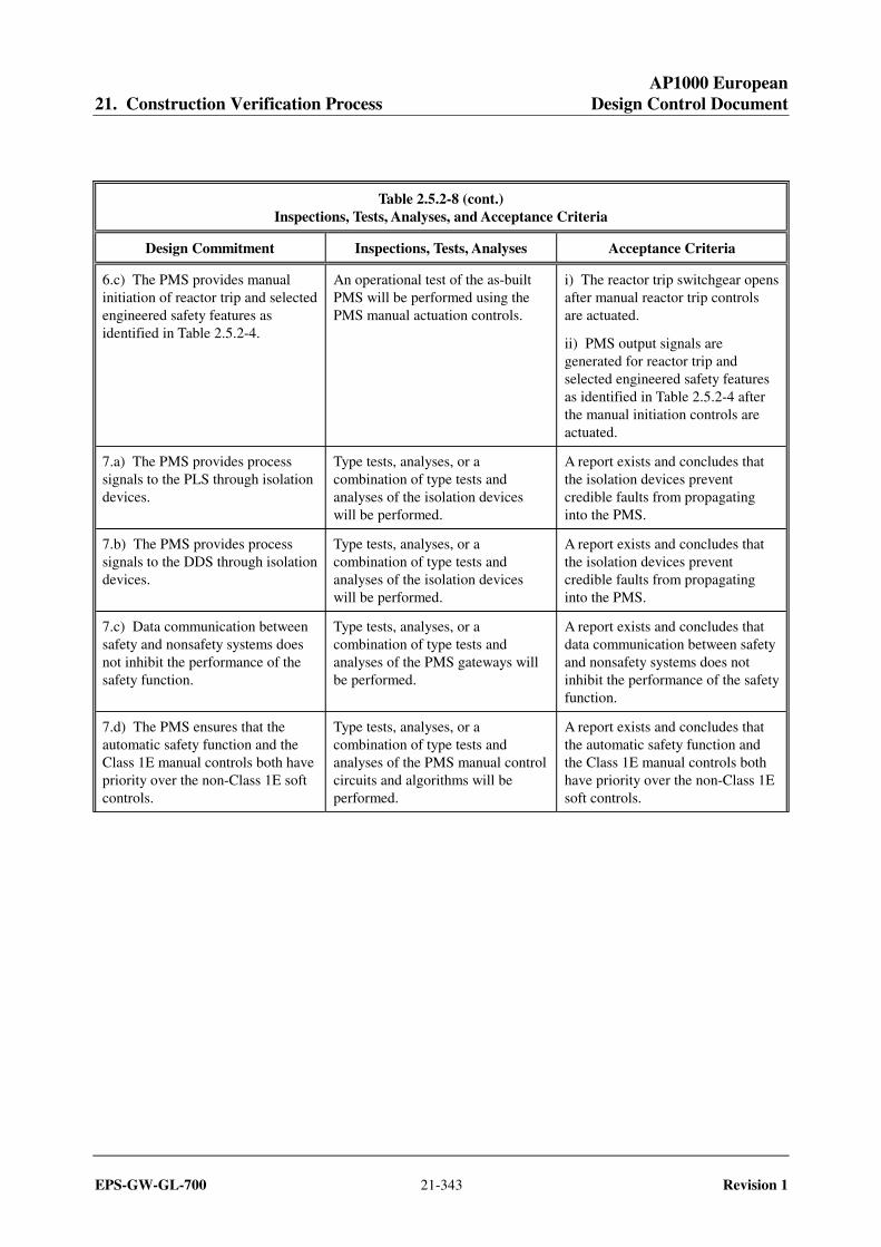
Table 2.5.2-8 (cont.) Inspections, Tests, Analyses, and Acceptance Criteria
Design Commitment Inspections, Tests, Analyses Acceptance Criteria
6.c) The PMS provides manual initiation of reactor trip and selected engineered safety features as identified in Table 2.5.2-4.
An operational test of the as-built PMS will be performed using the PMS manual actuation controls.
i) The reactor trip switchgear opens after manual reactor trip controls are actuated.
ii) PMS output signals are generated for reactor trip and selected engineered safety features as identified in Table 2.5.2-4 after the manual initiation controls are actuated.
7.a) The PMS provides process signals to the PLS through isolation devices.
Type tests, analyses, or a combination of type tests and analyses of the isolation devices will be performed.
A report exists and concludes that the isolation devices prevent credible faults from propagating into the PMS.
7.b) The PMS provides process signals to the DDS through isolation devices.
Type tests, analyses, or a combination of type tests and analyses of the isolation devices will be performed.
A report exists and concludes that the isolation devices prevent credible faults from propagating into the PMS.
7.c) Data communication between safety and nonsafety systems does not inhibit the performance of the safety function.
Type tests, analyses, or a combination of type tests and analyses of the PMS gateways will be performed.
A report exists and concludes that data communication between safety and nonsafety systems does not inhibit the performance of the safety function.
7.d) The PMS ensures that the automatic safety function and the Class 1E manual controls both have priority over the non-Class 1E soft controls.
Type tests, analyses, or a combination of type tests and analyses of the PMS manual control circuits and algorithms will be performed.
A report exists and concludes that the automatic safety function and the Class 1E manual controls both have priority over the non-Class 1E soft controls.

AP1000 European 21. Construction Verification Process Design Control Document
EPS-GW-GL-700 21-344 Revision 1
Table 2.5.2-8 (cont.) Inspections, Tests, Analyses, and Acceptance Criteria
Design Commitment Inspections, Tests, Analyses Acceptance Criteria
8.a) The PMS provides for the minimum inventory of displays, visual alerts, and fixed position controls, as identified in Table 2.5.2-5. The plant parameters listed with a "Yes" in the "Display" column and visual alerts listed with a "Yes" in the "Alert" column can be retrieved in the MCR. The fixed position controls listed with a "Yes" in the "Control" column are provided in the MCR.
i) An inspection will be performed for retrievability of plant parameters in the MCR.
ii) An inspection and test will be performed to verify that the plant parameters are used to generate visual alerts that identify challenges to critical safety functions.
iii) An operational test of the as-built system will be performed using each MCR fixed position control.
i) The plant parameters listed in Table 2.5.2-5 with a "Yes" in the "Display" column, can be retrieved in the MCR.
ii) The plant parameters listed in Table 2.5.2-5 with a "Yes" in the "Alert" column are used to generate visual alerts that identify challenges to critical safety functions. The visual alerts actuate in accordance with their correct logic and values.
iii) For each test of an as-built fixed position control listed in Table 2.5.2-5 with a "Yes" in the "Control" column, an actuation signal is generated. Tests from the actuation signal to the actuated device(s) are performed as part of the system-related inspection, test, analysis and acceptance criteria.
8.b) The PMS provides for the transfer of control capability from the MCR to the RSW using multiple transfer switches. Each individual transfer switch is associated with only a single safety-related group or with nonsafety-related control capability.
i) An inspection will be performed to verify that a transfer switch exists for each safety-related division and the nonsafety-related control capability.
ii) An operational test of the as-built system will be performed to demonstrate the transfer of control capability from the MCR to the RSW.
i) A transfer switch exists for each safety-related division and the nonsafety-related control capability.
ii) Actuation of each transfer switch results in an alarm in the MCR and RSW, the activation of operator control capability from the RSW, and the deactivation of operator control capability from the MCR for the associated safety-related division and nonsafety-related control capability.
8.c) Displays of the open/closed status of the reactor trip breakers can be retrieved in the MCR.
Inspection will be performed for retrievability of displays of the open/closed status of the reactor trip breakers in the MCR.
Displays of the open/closed status of the reactor trip breakers can be retrieved in the MCR.
AP1000 European 21. Construction Verification Process Design Control Document
EPS-GW-GL-700 21-345 Revision 1
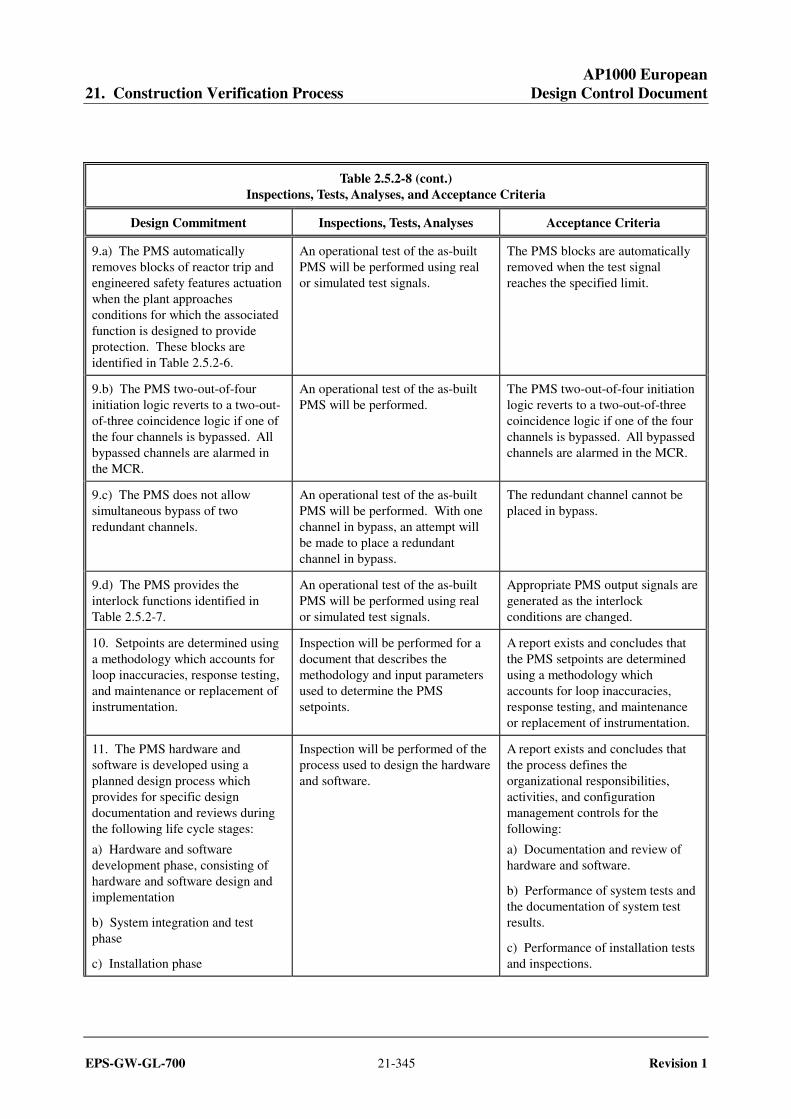
Table 2.5.2-8 (cont.) Inspections, Tests, Analyses, and Acceptance Criteria
Design Commitment Inspections, Tests, Analyses Acceptance Criteria
9.a) The PMS automatically removes blocks of reactor trip and engineered safety features actuation when the plant approaches conditions for which the associated function is designed to provide protection. These blocks are identified in Table 2.5.2-6.
An operational test of the as-built PMS will be performed using real or simulated test signals.
The PMS blocks are automatically removed when the test signal reaches the specified limit.
9.b) The PMS two-out-of-four initiation logic reverts to a two-out-of-three coincidence logic if one of the four channels is bypassed. All bypassed channels are alarmed in the MCR.
An operational test of the as-built PMS will be performed.
The PMS two-out-of-four initiation logic reverts to a two-out-of-three coincidence logic if one of the four channels is bypassed. All bypassed channels are alarmed in the MCR.
9.c) The PMS does not allow simultaneous bypass of two redundant channels.
An operational test of the as-built PMS will be performed. With one channel in bypass, an attempt will be made to place a redundant channel in bypass.
The redundant channel cannot be placed in bypass.
9.d) The PMS provides the interlock functions identified in Table 2.5.2-7.
An operational test of the as-built PMS will be performed using real or simulated test signals.
Appropriate PMS output signals are generated as the interlock conditions are changed.
10. Setpoints are determined using a methodology which accounts for loop inaccuracies, response testing, and maintenance or replacement of instrumentation.
Inspection will be performed for a document that describes the methodology and input parameters used to determine the PMS setpoints.
A report exists and concludes that the PMS setpoints are determined using a methodology which accounts for loop inaccuracies, response testing, and maintenance or replacement of instrumentation.
11. The PMS hardware and software is developed using a planned design process which provides for specific design documentation and reviews during the following life cycle stages:
a) Hardware and software development phase, consisting of hardware and software design and implementation
b) System integration and test phase
c) Installation phase
Inspection will be performed of the process used to design the hardware and software.
A report exists and concludes that the process defines the organizational responsibilities, activities, and configuration management controls for the following:
a) Documentation and review of hardware and software.
b) Performance of system tests and the documentation of system test results.
c) Performance of installation tests and inspections.

AP1000 European 21. Construction Verification Process Design Control Document
EPS-GW-GL-700 21-346 Revision 1
Table 2.5.2-8 (cont.) Inspections, Tests, Analyses, and Acceptance Criteria
Design Commitment Inspections, Tests, Analyses Acceptance Criteria
12. The PMS software is designed, tested, installed, and maintained using a process which incorporates a graded approach according to the relative importance of the software to safety and specifies requirements for:
a) Software management including documentation requirements, standards, review requirements, and procedures for problem reporting and corrective action.
b) Software configuration management including historical records of software and control of software changes.
c) Verification and validation including requirements for reviewer independence.
Inspection will be performed of the process used to design, test, install, and maintain the PMS software.
A report exists and concludes that the process establishes a method for classifying the PMS software elements according to their relative importance to safety and specifies requirements for software assigned to each safety classification. The report also concludes that requirements are provided for the following software development functions:
a) Software management including documentation requirements, standards, review requirements, and procedures for problem reporting and corrective action. Software management requirements may be documented in the software quality assurance plan, software management plan, software development plan, software safety plan, and software operation and maintenance plan; or these requirements may be combined into a single software management plan.
b) Software configuration management including historical records of software and control of software changes. Software configuration management requirements are provided in the software configuration management plan.
c) Verification and validation including requirements for reviewer independence. Verification and validation requirements are provided in the verification and validation plan.
AP1000 European 21. Construction Verification Process Design Control Document
EPS-GW-GL-700 21-347 Revision 1
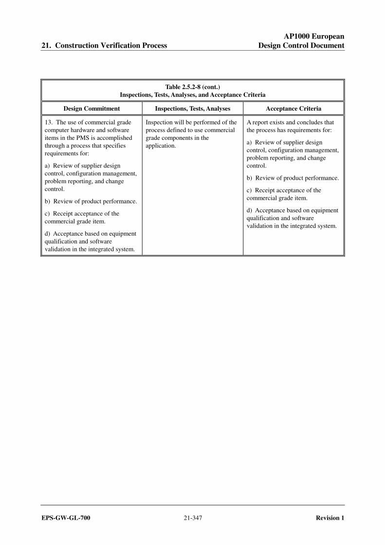
Table 2.5.2-8 (cont.) Inspections, Tests, Analyses, and Acceptance Criteria
Design Commitment Inspections, Tests, Analyses Acceptance Criteria
13. The use of commercial grade computer hardware and software items in the PMS is accomplished through a process that specifies requirements for:
a) Review of supplier design control, configuration management, problem reporting, and change control.
b) Review of product performance.
c) Receipt acceptance of the commercial grade item.
d) Acceptance based on equipment qualification and software validation in the integrated system.
Inspection will be performed of the process defined to use commercial grade components in the application.
A report exists and concludes that the process has requirements for:
a) Review of supplier design control, configuration management, problem reporting, and change control.
b) Review of product performance.
c) Receipt acceptance of the commercial grade item.
d) Acceptance based on equipment qualification and software validation in the integrated system.
AP1000 European 21. Construction Verification Process Design Control Document
EPS-GW-GL-700 21-348 Revision 1
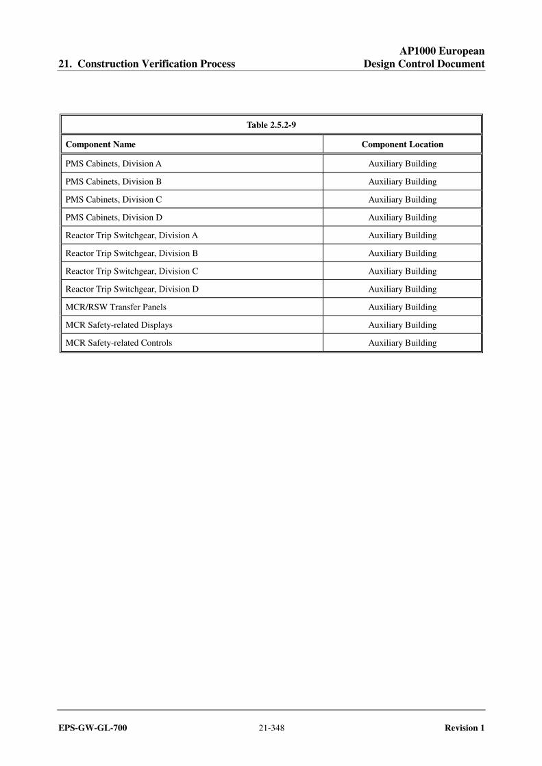
Table 2.5.2-9
Component Name Component Location
PMS Cabinets, Division A Auxiliary Building
PMS Cabinets, Division B Auxiliary Building
PMS Cabinets, Division C Auxiliary Building
PMS Cabinets, Division D Auxiliary Building
Reactor Trip Switchgear, Division A Auxiliary Building
Reactor Trip Switchgear, Division B Auxiliary Building
Reactor Trip Switchgear, Division C Auxiliary Building
Reactor Trip Switchgear, Division D Auxiliary Building
MCR/RSW Transfer Panels Auxiliary Building
MCR Safety-related Displays Auxiliary Building
MCR Safety-related Controls Auxiliary Building
AP1000 European 21. Construction Verification Process Design Control Document
EPS-GW-GL-700 21-349 Revision 1
Figure 2.5.2-1 Protection and Safety Monitoring System

AP1000 European 21. Construction Verification Process Design Control Document
EPS-GW-GL-700 21-350 Revision 1
2.5.3 Plant Control System
Design Description
The plant control system (PLS) provides for automatic and manual control of nonsafety-related plant components during normal and emergency plant operations. The PLS has distributed controllers and operator controls interconnected by computer data links or data highways.
1. The functional arrangement of the PLS is as described in the Design Description of this Section 2.5.3.
2. The PLS provides control interfaces for the control functions listed in Table 2.5.3-1.
Inspections, Tests, Analyses, and Acceptance Criteria
Table 2.5.3-2 specifies the inspections, tests, analyses, and associated acceptance criteria for the PLS.

AP1000 European 21. Construction Verification Process Design Control Document
EPS-GW-GL-700 21-351 Revision 1
Table 2.5.3-1 Control Functions Supported by the PLS
1. Reactor Power
2. Reactor Rod Position
3. Pressurizer Pressure
4. Pressurizer Water Level
5. Steam Generator Feedwater
6. Steam Dump
7. Rapid Power Reduction
Table 2.5.3-2 Inspections, Tests, Analyses, and Acceptance Criteria
Design Commitment Inspections, Tests, Analyses Acceptance Criteria
1. The functional arrangement of the PLS is as described in the Design Description of this Section 2.5.3.
Inspection of the as-built system will be performed.
The as-built PLS conforms with the functional arrangement as described in the Design Description of this Section 2.5.3.
2. The PLS provides control interfaces for the control functions listed in Table 2.5.3-1.
An operational test of the system will be performed using simulated input signals. System outputs or component operations will be monitored to determine the operability of the control functions.
The PLS provides control interfaces for the control functions listed in Table 2.5.3-1.
AP1000 European 21. Construction Verification Process Design Control Document
EPS-GW-GL-700 21-352 Revision 1
2.5.4 Data Display and Processing System
Design Description
The data display and processing system (DDS) provides nonsafety-related alarms and displays, analysis of plant data, plant data logging and historical storage and retrieval, and operational support for plant personnel. The DDS has distributed computer processors and video display units to support the data processing and display functions.
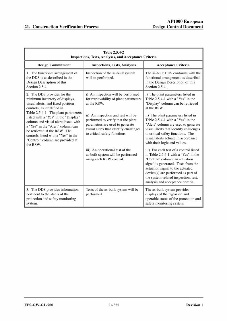
1. The functional arrangement of the DDS is as described in the Design Description of this Section 2.5.4.
2. The DDS, in conjunction with the operator workstations, provides the following function:
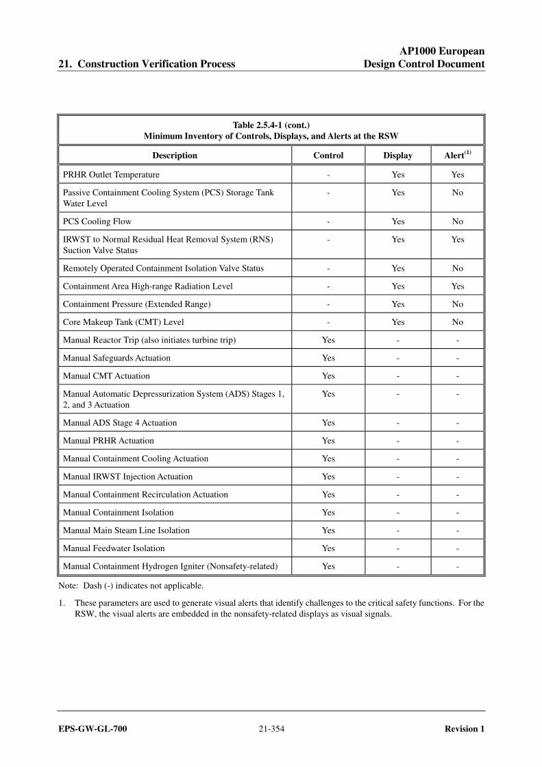
The DDS provides for the minimum inventory of displays, visual alerts, and fixed position controls, as identified in Table 2.5.4-1. The plant parameters listed with a "Yes" in the "Display" column and visual alerts listed with a "Yes" in the "Alert" column can be retrieved at the remote shutdown workstation (RSW). The controls listed with a "Yes" in the "Control" column are provided at the RSW.
3. The DDS provides information pertinent to the status of the protection and safety monitoring system. Inspections, Tests, Analyses, and Acceptance Criteria
Table 2.5.4-2 specifies the inspections, tests, analyses, and associated acceptance criteria for the DDS.

AP1000 European 21. Construction Verification Process Design Control Document
EPS-GW-GL-700 21-353 Revision 1
Table 2.5.4-1 Minimum Inventory of Controls, Displays, and Alerts at the RSW
Description Control Display Alert(1)
Neutron Flux - Yes Yes
Neutron Flux Doubling - No Yes
Startup Rate - Yes Yes
Reactor Coolant System (RCS) Pressure - Yes Yes
Wide-range Hot Leg Temperature - Yes No
Wide-range Cold Leg Temperature - Yes Yes
RCS Cooldown Rate Compared to the Limit Based on RCS Pressure
- Yes Yes
Wide-range Cold Leg Temperature Compared to the Limit Based on RCS Pressure
- Yes Yes
Change of RCS Temperature by more than 5°F in the last 10 minutes
- No Yes
Containment Water Level - Yes Yes
Containment Pressure - Yes Yes
Pressurizer Water Level - Yes Yes
Pressurizer Water Level Trend - Yes No
Pressurizer Reference Leg Temperature - Yes No
Reactor Vessel-Hot Leg Water Level - Yes Yes
Pressurizer Pressure - Yes No
Core Exit Temperature - Yes Yes
RCS Subcooling - Yes Yes
RCS Cold Overpressure Limit - Yes Yes
In-containment Refueling Water Storage Tank (IRWST) Water Level
- Yes Yes
Passive Residual Heat Removal (PRHR) Flow - Yes Yes
Note: Dash (-) indicates not applicable.
1. These parameters are used to generate visual alerts that identify challenges to the critical safety functions. For the RSW, the visual alerts are embedded in the nonsafety-related displays as visual signals.
AP1000 European 21. Construction Verification Process Design Control Document
EPS-GW-GL-700 21-354 Revision 1
Table 2.5.4-1 (cont.) Minimum Inventory of Controls, Displays, and Alerts at the RSW
Description Control Display Alert(1)
PRHR Outlet Temperature - Yes Yes
Passive Containment Cooling System (PCS) Storage Tank Water Level
- Yes No
PCS Cooling Flow - Yes No
IRWST to Normal Residual Heat Removal System (RNS) Suction Valve Status
- Yes Yes
Remotely Operated Containment Isolation Valve Status - Yes No
Containment Area High-range Radiation Level - Yes Yes
Containment Pressure (Extended Range) - Yes No
Core Makeup Tank (CMT) Level - Yes No
Manual Reactor Trip (also initiates turbine trip) Yes - -
Manual Safeguards Actuation Yes - -
Manual CMT Actuation Yes - -
Manual Automatic Depressurization System (ADS) Stages 1, 2, and 3 Actuation
Yes - -
Manual ADS Stage 4 Actuation Yes - -
Manual PRHR Actuation Yes - -
Manual Containment Cooling Actuation Yes - -
Manual IRWST Injection Actuation Yes - -
Manual Containment Recirculation Actuation Yes - -
Manual Containment Isolation Yes - -
Manual Main Steam Line Isolation Yes - -
Manual Feedwater Isolation Yes - -
Manual Containment Hydrogen Igniter (Nonsafety-related) Yes - -
Note: Dash (-) indicates not applicable.
1. These parameters are used to generate visual alerts that identify challenges to the critical safety functions. For the RSW, the visual alerts are embedded in the nonsafety-related displays as visual signals.
AP1000 European 21. Construction Verification Process Design Control Document
EPS-GW-GL-700 21-355 Revision 1
Table 2.5.4-2 Inspections, Tests, Analyses, and Acceptance Criteria
Design Commitment Inspections, Tests, Analyses Acceptance Criteria
1. The functional arrangement of the DDS is as described in the Design Description of this Section 2.5.4.
Inspection of the as-built system will be performed.
The as-built DDS conforms with the functional arrangement as described in the Design Description of this Section 2.5.4.
2. The DDS provides for the minimum inventory of displays, visual alerts, and fixed position controls, as identified in Table 2.5.4-1. The plant parameters listed with a "Yes" in the "Display" column and visual alerts listed with a "Yes" in the "Alert" column can be retrieved at the RSW. The controls listed with a "Yes" in the "Control" column are provided at the RSW.
i) An inspection will be performed for retrievability of plant parameters at the RSW.
ii) An inspection and test will be performed to verify that the plant parameters are used to generate visual alerts that identify challenges to critical safety functions.
iii) An operational test of the as-built system will be performed using each RSW control.
i) The plant parameters listed in Table 2.5.4-1 with a "Yes" in the "Display" column can be retrieved at the RSW.
ii) The plant parameters listed in Table 2.5.4-1 with a "Yes" in the "Alert" column are used to generate visual alerts that identify challenges to critical safety functions. The visual alerts actuate in accordance with their logic and values.
iii) For each test of a control listed in Table 2.5.4-1 with a "Yes" in the "Control" column, an actuation signal is generated. Tests from the actuation signal to the actuated device(s) are performed as part of the system-related inspection, test, analysis and acceptance criteria.
3. The DDS provides information pertinent to the status of the protection and safety monitoring system.
Tests of the as-built system will be performed.
The as-built system provides displays of the bypassed and operable status of the protection and safety monitoring system.

AP1000 European 21. Construction Verification Process Design Control Document
EPS-GW-GL-700 21-356 Revision 1
2.5.5 In-Core Instrumentation System
Design Description
The in-core instrumentation system (IIS) provides safety-related core exit thermocouple signals to the protection and safety monitoring system (PMS). The IIS also provides nonsafety-related core exit thermocouple signals to the diverse actuation system (DAS). The core exit thermocouples are housed in the core instrument assemblies. Multiple core instrument assemblies are used to provide radial coverage of the core. At least three core instrument assemblies are provided in each core quadrant.
1. The functional arrangement of the IIS is as described in the Design Description of this Section 2.5.5.
2. The seismic Category I equipment identified in Table 2.5.5-1 can withstand seismic design basis loads without loss of safety function.
3. a) The Class 1E equipment identified in Table 2.5.5-1 as being qualified for a harsh environment can withstand environmental conditions that would exist before, during, and following a design basis accident without loss of safety function, for the time required to perform the safety function.
b) The Class 1E cables between the Incore Thermocouple elements and the connector boxes located on the integrated head package have sheaths.
c) For cables other than those covered by 3.b, separation is provided between IIS Class 1E divisions, and between Class 1E divisions and non-Class 1E cable.
4. Safety-related displays of the parameters identified in Table 2.5.5-1 can be retrieved in the main control room (MCR).
Inspections, Tests, Analyses, and Acceptance Criteria
Table 2.5.5-2 specifies the inspections, tests, analyses, and associated acceptance criteria for the IIS.
AP1000 European 21. Construction Verification Process Design Control Document
EPS-GW-GL-700 21-357 Revision 1
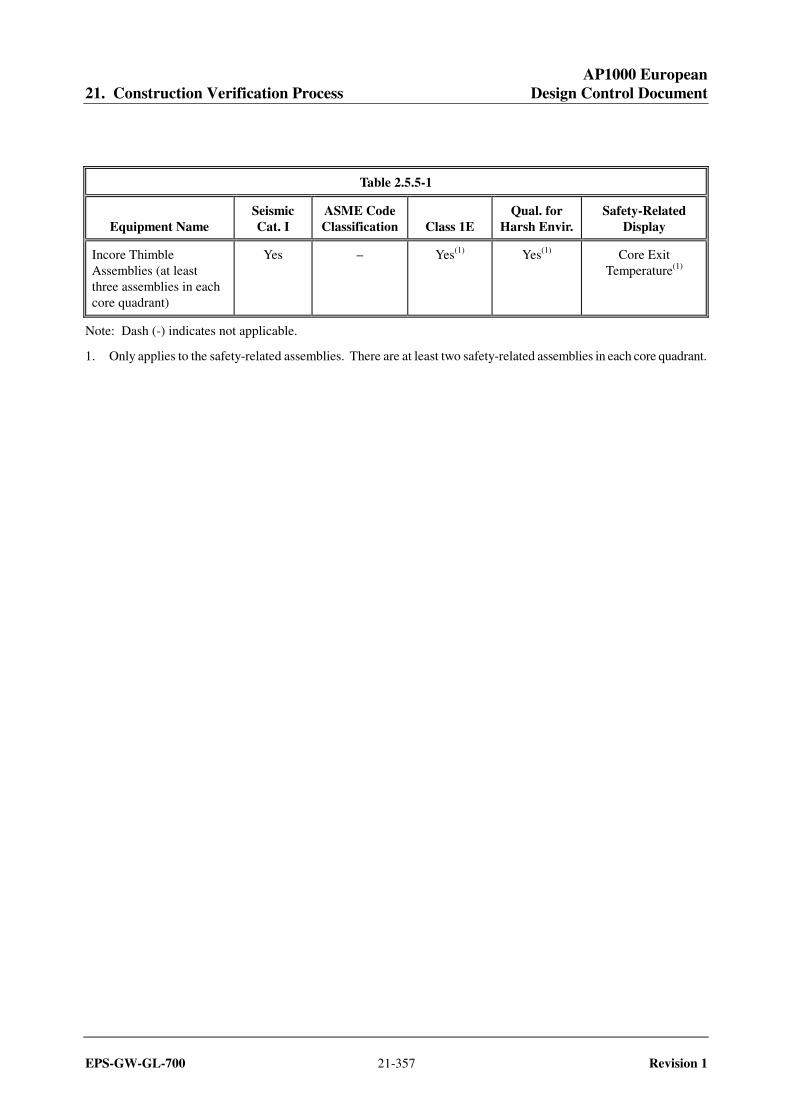
Table 2.5.5-1
Equipment Name Seismic Cat. I
ASME Code Classification Class 1E
Qual. for Harsh Envir.
Safety-Related Display
Incore Thimble Assemblies (at least three assemblies in each core quadrant)
Yes – Yes(1) Yes(1) Core Exit Temperature(1)
Note: Dash (-) indicates not applicable.
1. Only applies to the safety-related assemblies. There are at least two safety-related assemblies in each core quadrant.
AP1000 European 21. Construction Verification Process Design Control Document
EPS-GW-GL-700 21-358 Revision 1
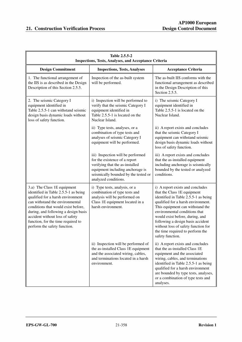
Table 2.5.5-2 Inspections, Tests, Analyses, and Acceptance Criteria
Design Commitment Inspections, Tests, Analyses Acceptance Criteria
1. The functional arrangement of the IIS is as described in the Design Description of this Section 2.5.5.
Inspection of the as-built system will be performed.
The as-built IIS conforms with the functional arrangement as described in the Design Description of this Section 2.5.5.
2. The seismic Category I equipment identified in Table 2.5.5-1 can withstand seismic design basis dynamic loads without loss of safety function.
i) Inspection will be performed to verify that the seismic Category I equipment identified in Table 2.5.5-1 is located on the Nuclear Island.
ii) Type tests, analyses, or a combination of type tests and analyses of seismic Category I equipment will be performed.
iii) Inspection will be performed for the existence of a report verifying that the as-installed equipment including anchorage is seismically bounded by the tested or analyzed conditions.
i) The seismic Category I equipment identified in Table 2.5.5-1 is located on the Nuclear Island.
ii) A report exists and concludes that the seismic Category I equipment can withstand seismic design basis dynamic loads without loss of safety function.
iii) A report exists and concludes that the as-installed equipment including anchorage is seismically bounded by the tested or analyzed conditions.
3.a) The Class 1E equipment identified in Table 2.5.5-1 as being qualified for a harsh environment can withstand the environmental conditions that would exist before, during, and following a design basis accident without loss of safety function, for the time required to perform the safety function.
i) Type tests, analysis, or a combination of type tests and analysis will be performed on Class 1E equipment located in a harsh environment.
ii) Inspection will be performed of the as-installed Class 1E equipment and the associated wiring, cables, and terminations located in a harsh environment.
i) A report exists and concludes that the Class 1E equipment identified in Table 2.5.5-1 as being qualified for a harsh environment. This equipment can withstand the environmental conditions that would exist before, during, and following a design basis accident without loss of safety function for the time required to perform the safety function.
ii) A report exists and concludes that the as-installed Class 1E equipment and the associated wiring, cables, and terminations identified in Table 2.5.5-1 as being qualified for a harsh environment are bounded by type tests, analyses, or a combination of type tests and analyses.
AP1000 European 21. Construction Verification Process Design Control Document
EPS-GW-GL-700 21-359 Revision 1
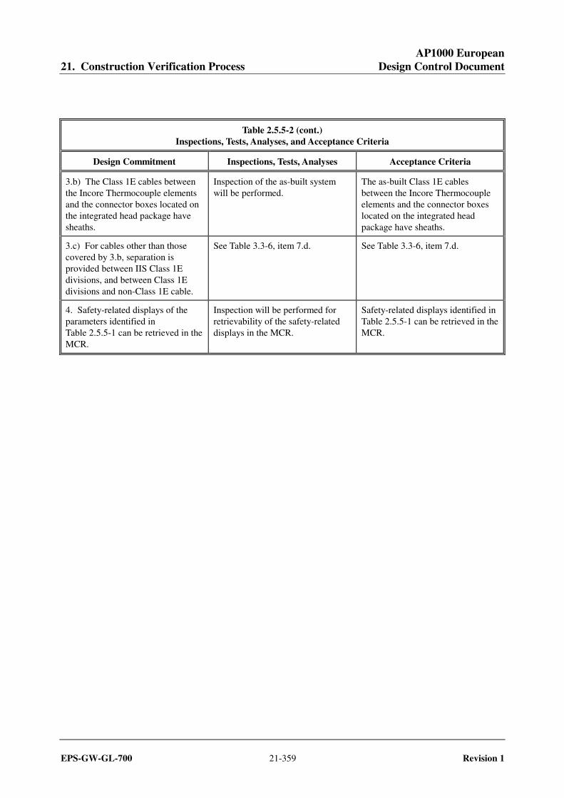
Table 2.5.5-2 (cont.) Inspections, Tests, Analyses, and Acceptance Criteria
Design Commitment Inspections, Tests, Analyses Acceptance Criteria
3.b) The Class 1E cables between the Incore Thermocouple elements and the connector boxes located on the integrated head package have sheaths.
Inspection of the as-built system will be performed.
The as-built Class 1E cables between the Incore Thermocouple elements and the connector boxes located on the integrated head package have sheaths.
3.c) For cables other than those covered by 3.b, separation is provided between IIS Class 1E divisions, and between Class 1E divisions and non-Class 1E cable.
See Table 3.3-6, item 7.d. See Table 3.3-6, item 7.d.
4. Safety-related displays of the parameters identified in Table 2.5.5-1 can be retrieved in the MCR.
Inspection will be performed for retrievability of the safety-related displays in the MCR.
Safety-related displays identified in Table 2.5.5-1 can be retrieved in the MCR.

AP1000 European 21. Construction Verification Process Design Control Document
EPS-GW-GL-700 21-360 Revision 1
2.5.6 Special Monitoring System
Design Description
The special monitoring system (SMS) monitors the reactor coolant system (RCS) for the occurrence of impacts characteristic of metallic loose parts. Metal impact monitoring sensors are provided to monitor the RCS at the upper and lower head region of the reactor pressure vessel, and at the reactor coolant inlet region of each steam generator.
1. The functional arrangement of the SMS is as described in the Design Description of this Section 2.5.6.
2. Data obtained from the metal impact monitoring sensors can be retrieved in the main control room (MCR).
Inspections, Tests, Analyses, and Acceptance Criteria
Table 2.5.6-1 specifies the inspections, tests, analyses, and associated acceptance criteria for the SMS.
Table 2.5.6-1 Inspections, Tests, Analyses, and Acceptance Criteria
Design Commitment Inspections, Tests, Analyses Acceptance Criteria
1. The functional arrangement of the SMS is as described in the Design Description of this Section 2.5.6.
Inspection of the as-built system will be performed.
The as-built SMS conforms with the functional arrangement as described in the Design Description of this Section 2.5.6.
2. Data obtained from the metal impact monitoring sensors can be retrieved in the MCR.
Inspection will be performed for retrievability of data from the metal impact monitoring sensors in the MCR.
Data obtained from the metal impact monitoring sensors can be retrieved in the MCR.
AP1000 European 21. Construction Verification Process Design Control Document
EPS-GW-GL-700 21-361 Revision 1
2.5.7 Operation and Control Centers System
Design Description
The operation and control centers system (OCS) is developed and implemented based upon a human factors engineering (HFE) program. The human system interface (HSI) scope includes the design of the OCS and each of the HSI resources. For the purposes of the HFE program, the OCS includes the main control room, remote shutdown workstation, the local control stations, and the associated workstations for each of these centers. Implementation of the HFE program involves the completion of the human factors engineering analyses and plans described in Section 3.2, Human Factors Engineering.
Inspections, Tests, Analyses, and Acceptance Criteria
The inspections, tests, analyses, and associated acceptance criteria for the OCS are provided in Table 3.2-1.
AP1000 European 21. Construction Verification Process Design Control Document
EPS-GW-GL-700 21-362 Revision 1
2.5.8 Radiation Monitoring System
No entry. Radiation monitoring function covered in Section 3.5, Radiation Monitoring.

AP1000 European 21. Construction Verification Process Design Control Document
EPS-GW-GL-700 21-363 Revision 1
2.5.9 Seismic Monitoring System
Design Description
The seismic monitoring system (SJS) provides for the collection of seismic data in digital format, analysis of seismic data, notification of the operator if the ground motion exceeds a threshold value, and notification of the operator (after analysis of data) that a predetermined cumulative absolute velocity (CAV) has been exceeded. The SJS has at least four triaxial acceleration sensor units and a time-history analyzer and recording system. The time-history analyzer and recording system are located in the auxiliary building.
1. The functional arrangement of the SJS is as described in the Design Description of this Section 2.5.9.
2. The SJS can compute CAV and the 5 percent of critical damping response spectrum for frequencies between 1 and 10 Hertz.
3. The SJS has a dynamic range of 0.001g to 1.0g and a frequency range of 0.2 to 50 Hertz.
Inspections, Tests, Analyses, and Acceptance Criteria
Table 2.5.9-1 specifies the inspections, tests, analyses, and associated acceptance criteria for SJS.
AP1000 European 21. Construction Verification Process Design Control Document
EPS-GW-GL-700 21-364 Revision 1
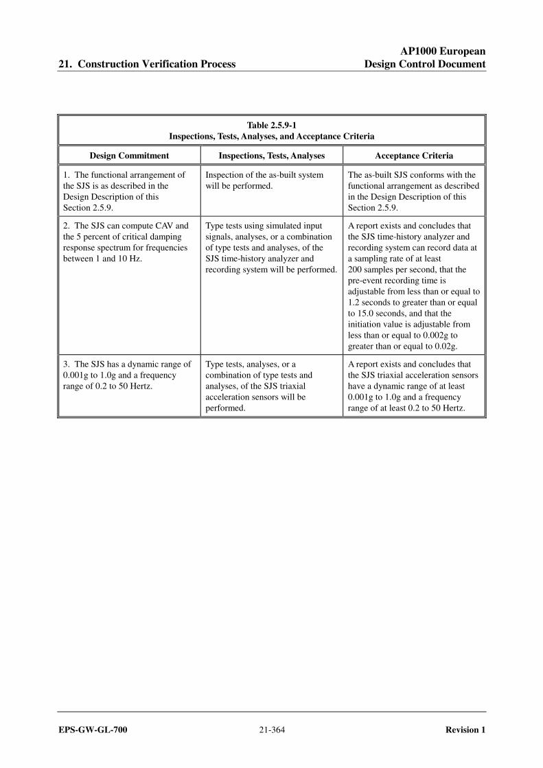
Table 2.5.9-1 Inspections, Tests, Analyses, and Acceptance Criteria
Design Commitment Inspections, Tests, Analyses Acceptance Criteria
1. The functional arrangement of the SJS is as described in the Design Description of this Section 2.5.9.
Inspection of the as-built system will be performed.
The as-built SJS conforms with the functional arrangement as described in the Design Description of this Section 2.5.9.
2. The SJS can compute CAV and the 5 percent of critical damping response spectrum for frequencies between 1 and 10 Hz.
Type tests using simulated input signals, analyses, or a combination of type tests and analyses, of the SJS time-history analyzer and recording system will be performed.
A report exists and concludes that the SJS time-history analyzer and recording system can record data at a sampling rate of at least 200 samples per second, that the pre-event recording time is adjustable from less than or equal to 1.2 seconds to greater than or equal to 15.0 seconds, and that the initiation value is adjustable from less than or equal to 0.002g to greater than or equal to 0.02g.
3. The SJS has a dynamic range of 0.001g to 1.0g and a frequency range of 0.2 to 50 Hertz.
Type tests, analyses, or a combination of type tests and analyses, of the SJS triaxial acceleration sensors will be performed.
A report exists and concludes that the SJS triaxial acceleration sensors have a dynamic range of at least 0.001g to 1.0g and a frequency range of at least 0.2 to 50 Hertz.

AP1000 European 21. Construction Verification Process Design Control Document
EPS-GW-GL-700 21-365 Revision 1
2.5.10 Main Turbine Control and Diagnostic System
No entry. Covered in Section 2.4.2, Main Turbine System.