ap-2000iq digital inverter generator ow ner’s...
TRANSCRIPT

AP-2000iQ Digital Inverter Generator
Ow ner’s Manual
W ARNING! To R educe R isk of Injury, User Must R ead and Understand Ow ner’ s Manual Prior to Use.
NOTE: Retain Original Sales Receipt as Proof of Purchase!
W ARNING! To R educe R isk of Injury,

2
Notes
____________________________________________________________________________________________________________________________________________________________________________________________________________________________________________________________________________________________________________________________________________________________________________________________________________________________________________________________________________________________________________________________________________________________________________________________________________________________________________________________________________________________________________________________________________________________________________________
3
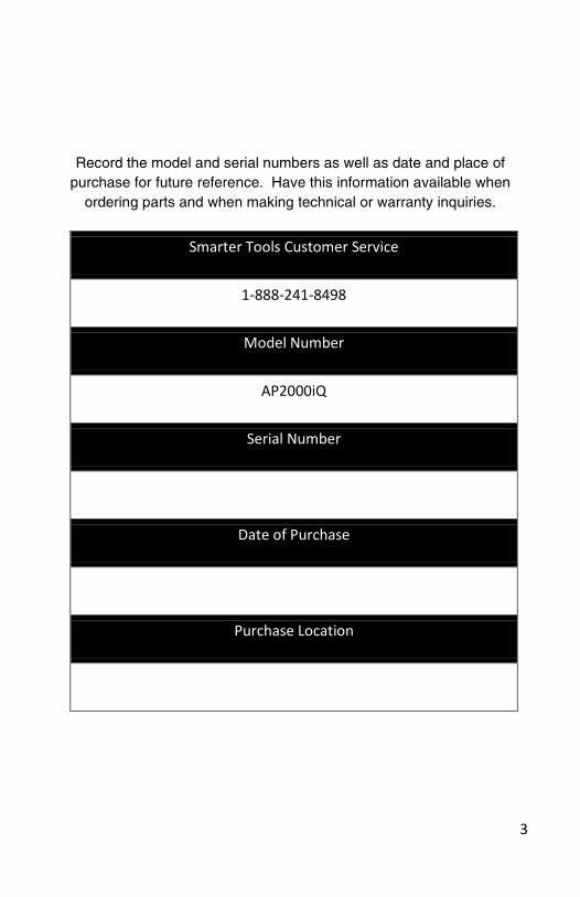
Record the model and serial numbers as well as date and place of purchase for future reference. Have this information available when
ordering parts and when making technical or warranty inquiries.
Smarter Tools Customer Service
1-888-241-8498
Model Number
AP2000iQ
Serial Number
Date of Purchase
Purchase Location
4
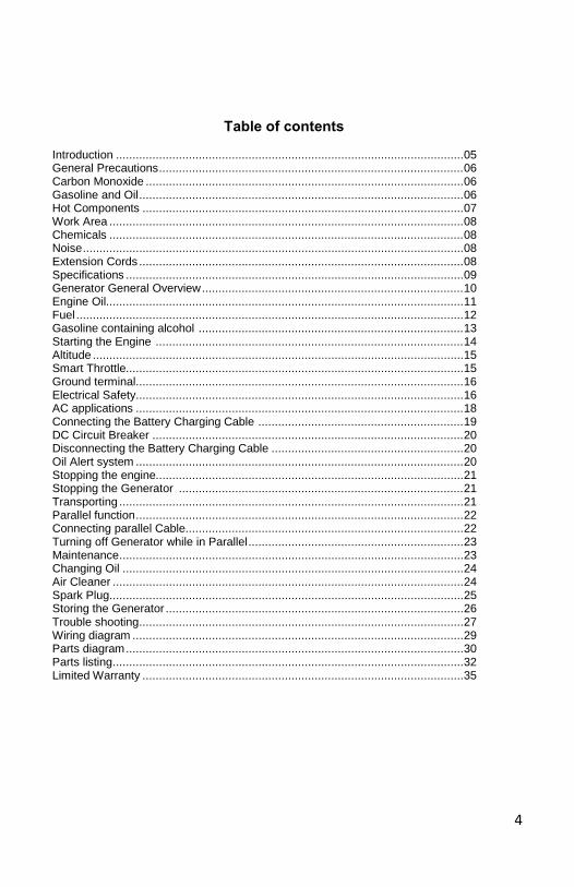
Table of contents
Introduction ......................................................................................................... 05 General Precautions ............................................................................................ 06 Carbon Monoxide ................................................................................................ 06 Gasoline and Oil .................................................................................................. 06 Hot Components ................................................................................................. 07 Work Area ........................................................................................................... 08 Chemicals ........................................................................................................... 08 Noise ................................................................................................................... 08 Extension Cords .................................................................................................. 08 Specifications ...................................................................................................... 09 Generator General Overview ............................................................................... 10 Engine Oil............................................................................................................ 11 Fuel ..................................................................................................................... 12 Gasoline containing alcohol ................................................................................ 13 Starting the Engine ............................................................................................. 14 Altitude ................................................................................................................ 15 Smart Throttle...................................................................................................... 15 Ground terminal ................................................................................................... 16 Electrical Safety ................................................................................................... 16 AC applications ................................................................................................... 18 Connecting the Battery Charging Cable .............................................................. 19 DC Circuit Breaker .............................................................................................. 20 Disconnecting the Battery Charging Cable .......................................................... 20 Oil Alert system ................................................................................................... 20 Stopping the engine............................................................................................. 21 Stopping the Generator ...................................................................................... 21 Transporting ........................................................................................................ 21 Parallel function ................................................................................................... 22 Connecting parallel Cable.................................................................................... 22 Turning off Generator while in Parallel ................................................................. 23 Maintenance ........................................................................................................ 23 Changing Oil ....................................................................................................... 24 Air Cleaner .......................................................................................................... 24 Spark Plug ........................................................................................................... 25 Storing the Generator .......................................................................................... 26 Trouble shooting .................................................................................................. 27 Wiring diagram .................................................................................................... 29 Parts diagram ...................................................................................................... 30 Parts listing .......................................................................................................... 32 Limited Warranty ................................................................................................. 35
5
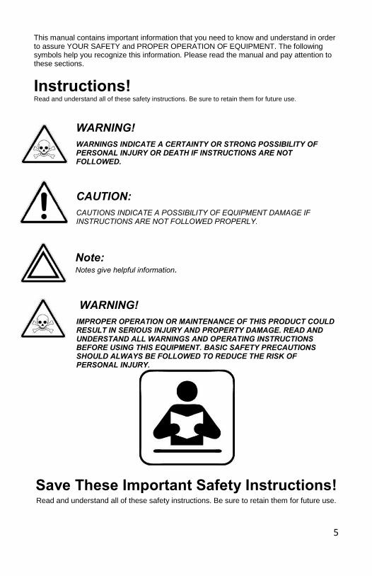
This manual contains important information that you need to know and understand in order to assure YOUR SAFETY and PROPER OPERATION OF EQUIPMENT. The following symbols help you recognize this information. Please read the manual and pay attention to these sections.
Instructions! Read and understand all of these safety instructions. Be sure to retain them for future use.
WARNING! WARNINGS INDICATE A CERTAINTY OR STRONG POSSIBILITY OF PERSONAL INJURY OR DEATH IF INSTRUCTIONS ARE NOT FOLLOWED.
CAUTION: CAUTIONS INDICATE A POSSIBILITY OF EQUIPMENT DAMAGE IF INSTRUCTIONS ARE NOT FOLLOWED PROPERLY.
Note: Notes give helpful information. WARNING! IMPROPER OPERATION OR MAINTENANCE OF THIS PRODUCT COULD RESULT IN SERIOUS INJURY AND PROPERTY DAMAGE. READ AND UNDERSTAND ALL WARNINGS AND OPERATING INSTRUCTIONS BEFORE USING THIS EQUIPMENT. BASIC SAFETY PRECAUTIONS SHOULD ALWAYS BE FOLLOWED TO REDUCE THE RISK OF PERSONAL INJURY.
Save These Important Safety Instructions! Read and understand all of these safety instructions. Be sure to retain them for future use.
6
General Safety Precautions
WARNING! FAILURE TO FOLLOW THESE INSTRUCTIONS CAN RESULT IN SEVERE INJURY OR DEATH.
CAUTION: FAILURE TO FOLLOW THESE INSTRUCTIONS CAN ALSO RESULT IN DAMAGE TO THE EQUIPMENT AND/OR THE ITEM YOU ARE WORKING ON OR WITH.
Carbon Monoxide
• Carbon Monoxide is an odorless and colorless gas. Breathing exhaust that contains this poisonous gas can cause unconsciousness and may lead to death.
• The engine exhaust from this product contains chemicals recognized by the state of California to cause cancer, birth defects, or other reproductive harm.
• When this tool is running, ensure that the area is well ventilated. Never run the engine in an enclosed area. Run the engine in an open area or with an exhaust evacuation system in an enclosed area.
• NEVER use a generator inside homes, garages, crawlspaces, or other partially enclosed areas. Deadly levels of carbon monoxide can build up in these areas. Using a fan or opening windows and doors does NOT supply enough fresh air.
• ONLY use a generator outdoors and far away from open windows, doors, and vents. These openings can pull in generator exhaust.
• Even when you use a generator correctly, CO may leak into the home. ALWAYS use a battery-powered or battery-backup CO alarm in the home.
• If you start to feel sick, dizzy, or weak after the generator has been running, move to fresh air RIGHT AWAY. See a doctor. You could have carbon monoxide poisoning.
WARNING! THE EXHAUST CONTAINS POISONOUS CARBON MONOXIDE GAS THAT CAN CAUSE LOSS OF CONSCIOUSNESS AND MAY LEAD TO DEATH.
Gasoline and Oil This product requires oil and fuel. THE ENGINE WILL NOT START WITHOUT OIL. Work in well ventilated area. Keep cigarettes, flames or sparks away from the work area or where gasoline is stored.
WARNING! GASOLINE IS EXTREMELY FLAMMABLE AND IS EXPLOSIVE UNDER CERTAIN CONDITIONS. KEEP OUT OF REACH OF CHILDREN.
7
General Safety Precautions (cont’d) Gasoline and Oil (cont’d)
• Gasoline fuel and fumes are flammable and potentially explosive. Use proper fuel storage and handling procedures. Always have multiple ABC class fire extinguishers nearby.
• Keep the generator and surrounding area clean at all times. Keep the generator at least 5 feet away from buildings and other equipment during operation.
• Fuel or oil spills must be cleaned up immediately. Dispose of fluids and cleaning materials as per any local, state, or federal codes and regulations. Store oily rags in a covered metal container.
• Never store fuel or other flammable materials near the generator. • Do not smoke, or allow sparks, flames or other sources of ignition around the
engine and fuel tank. Fuel vapors are explosive. • Keep grounded conductive objects, such as tools, away from exposed, live
electrical parts and connections to avoid sparking or arcing. These events could ignite fumes or vapors.
• Do not refill the fuel tank while the engine is running or while the engine is still hot. Do not operate the generator with known leaks in the fuel system.
• Excessive buildup of unburned fuel gases in the exhaust system can create a potentially explosive condition. This buildup can occur after repeated failed start attempts, valve testing, or hot engine shutdown. If this occurs, open exhaust system drain plugs, if equipped, and allow the gases to dissipate before attempting to restart the generator.
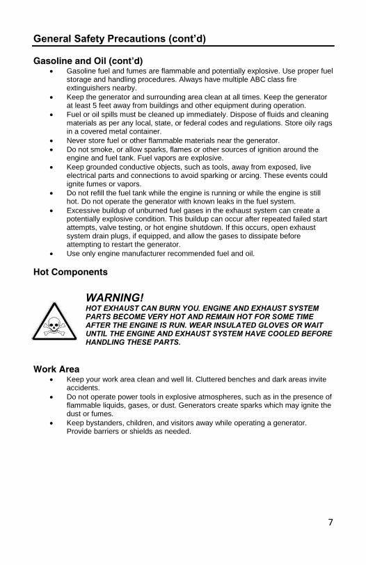
• Use only engine manufacturer recommended fuel and oil. Hot Components
WARNING! HOT EXHAUST CAN BURN YOU. ENGINE AND EXHAUST SYSTEM PARTS BECOME VERY HOT AND REMAIN HOT FOR SOME TIME AFTER THE ENGINE IS RUN. WEAR INSULATED GLOVES OR WAIT UNTIL THE ENGINE AND EXHAUST SYSTEM HAVE COOLED BEFORE HANDLING THESE PARTS.
Work Area
• Keep your work area clean and well lit. Cluttered benches and dark areas invite accidents.
• Do not operate power tools in explosive atmospheres, such as in the presence of flammable liquids, gases, or dust. Generators create sparks which may ignite the dust or fumes.
• Keep bystanders, children, and visitors away while operating a generator. Provide barriers or shields as needed.
8
Chemicals • Avoid contact with hot fuel, oil, exhaust fumes, and hot solid surfaces. • Avoid body contact with fuels, oils, and lubricants used in the generator. If
swallowed, seek medical treatment immediately. Do not induce vomiting if fuel is swallowed. For skin contact, immediately wash with soap and water. For eye contact, immediately flush eyes with clean water and seek medical attention.
Noise Prolonged exposure to noise levels above 85dBA is hazardous to hearing. Always wear ANSI approved ear protection when operating or working around the Generator when it is running.
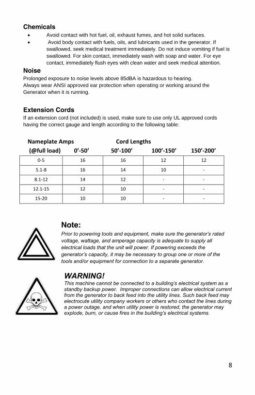
Extension Cords If an extension cord (not included) is used, make sure to use only UL approved cords having the correct gauge and length according to the following table: Nameplate Amps Cord Lengths (@full load) 0’-50’ 50’-100’ 100’-150’ 150’-200’
0-5 16 16 12 12
5.1-8 16 14 10 -
8.1-12 14 12 - -
12.1-15 12 10 - -
15-20 10 10 - -
Note: Prior to powering tools and equipment, make sure the generator’s rated voltage, wattage, and amperage capacity is adequate to supply all electrical loads that the unit will power. If powering exceeds the generator’s capacity, it may be necessary to group one or more of the tools and/or equipment for connection to a separate generator.
WARNING! This machine cannot be connected to a building’s electrical system as a standby backup power. Improper connections can allow electrical current from the generator to back feed into the utility lines. Such back feed may electrocute utility company workers or others who contact the lines during a power outage, and when utility power is restored, the generator may explode, burn, or cause fires in the building’s electrical systems.
9
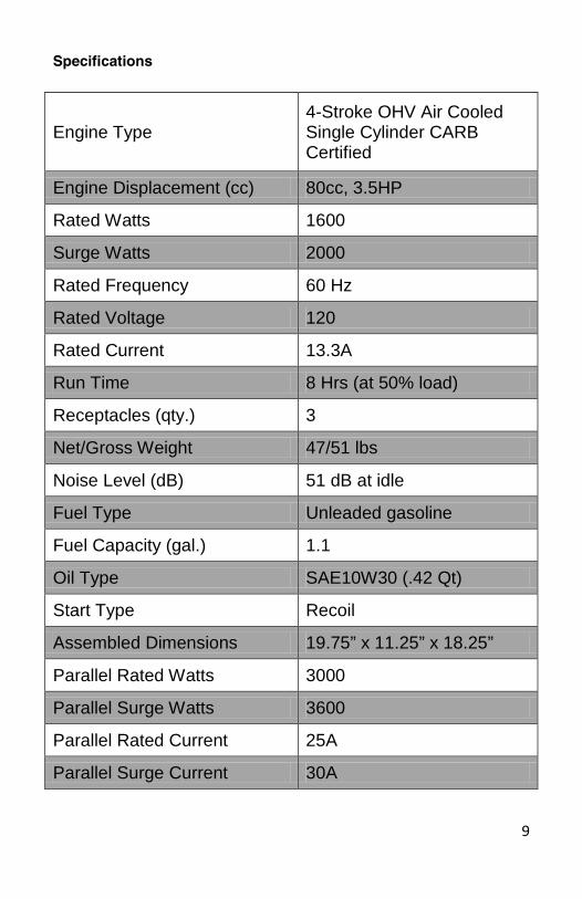
Specifications
Engine Type 4-Stroke OHV Air Cooled Single Cylinder CARB Certified
Engine Displacement (cc) 80cc, 3.5HP
Rated Watts 1600
Surge Watts 2000
Rated Frequency 60 Hz
Rated Voltage 120
Rated Current 13.3A
Run Time 8 Hrs (at 50% load)
Receptacles (qty.) 3
Net/Gross Weight 47/51 lbs
Noise Level (dB) 51 dB at idle
Fuel Type Unleaded gasoline
Fuel Capacity (gal.) 1.1
Oil Type SAE10W30 (.42 Qt)
Start Type Recoil
Assembled Dimensions 19.75” x 11.25” x 18.25”
Parallel Rated Watts 3000
Parallel Surge Watts 3600
Parallel Rated Current 25A
Parallel Surge Current 30A
10
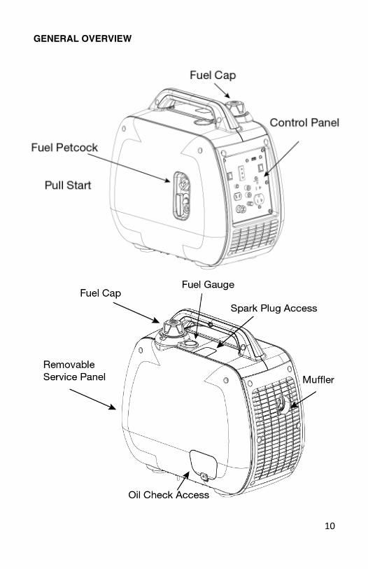
GENERAL OVERVIEW
11
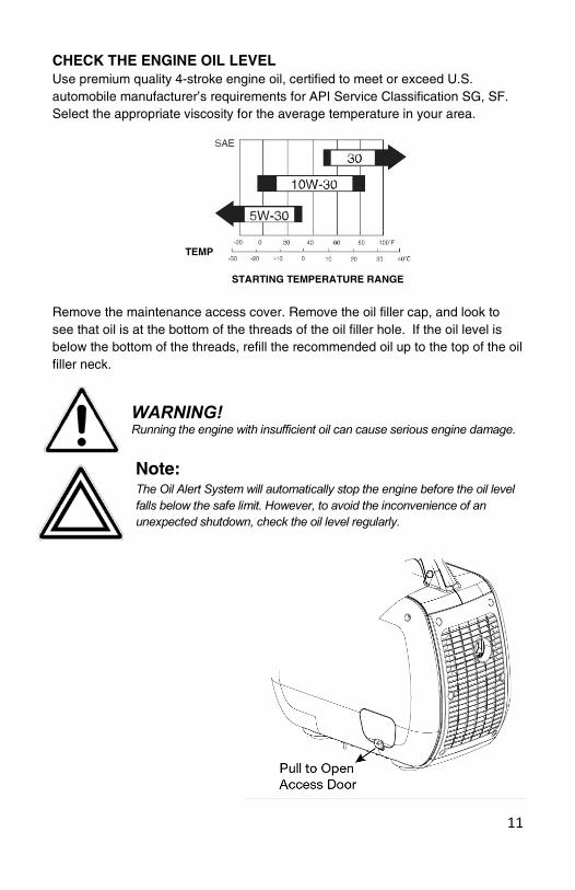
CHECK THE ENGINE OIL LEVEL Use premium quality 4-stroke engine oil, certified to meet or exceed U.S. automobile manufacturer’s requirements for API Service Classification SG, SF. Select the appropriate viscosity for the average temperature in your area.
TEMP STARTING TEMPERATURE RANGE
Remove the maintenance access cover. Remove the oil filler cap, and look to see that oil is at the bottom of the threads of the oil filler hole. If the oil level is below the bottom of the threads, refill the recommended oil up to the top of the oil filler neck.
WARNING!Running the engine with insufficient oil can cause serious engine damage.
Note: The Oil Alert System will automatically stop the engine before the oil level falls below the safe limit. However, to avoid the inconvenience of an unexpected shutdown, check the oil level regularly.
12
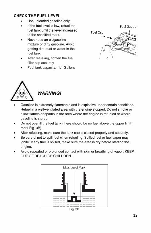
CHECK THE FUEL LEVEL • Use unleaded gasoline only. • If the fuel level is low, refuel the
fuel tank until the level increased to the specified mark.
• Never use an oil/gasoline mixture or dirty gasoline. Avoid getting dirt, dust or water in the fuel tank.
• After refueling, tighten the fuel filler cap securely
• Fuel tank capacity: 1.1 Gallons
WARNING!
• Gasoline is extremely flammable and is explosive under certain conditions. Refuel in a well-ventilated area with the engine stopped. Do not smoke or allow flames or sparks in the area where the engine is refueled or where gasoline is stored.
• Do not overfill the fuel tank (there should be no fuel above the upper limit mark Fig. 3B).
• After refueling, make sure the tank cap is closed properly and securely. • Be careful not to spill fuel when refueling. Spilled fuel or fuel vapor may
ignite. If any fuel is spilled, make sure the area is dry before starting the engine.
• Avoid repeated or prolonged contact with skin or breathing of vapor. KEEP OUT OF REACH OF CHILDREN.
13
GASOLINE CONTAINING ALCOHOL Do not use gasoline that contains more than 10% ethanol.
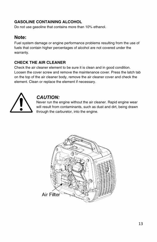
Note: Fuel system damage or engine performance problems resulting from the use of fuels that contain higher percentages of alcohol are not covered under the warranty. CHECK THE AIR CLEANER Check the air cleaner element to be sure it is clean and in good condition. Loosen the cover screw and remove the maintenance cover. Press the latch tab on the top of the air cleaner body, remove the air cleaner cover and check the element. Clean or replace the element if necessary.
CAUTION: Never run the engine without the air cleaner. Rapid engine wear will result from contaminants, such as dust and dirt, being drawn through the carburetor, into the engine.
14
WARNING! Never run the generator indoors or in a poorly ventilated area. Engine exhaust contains carbon monoxide, and odorless and deadly gas.
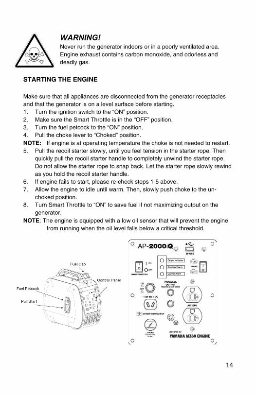
STARTING THE ENGINE Make sure that all appliances are disconnected from the generator receptacles and that the generator is on a level surface before starting. 1. Turn the ignition switch to the “ON” position. 2. Make sure the Smart Throttle is in the “OFF” position. 3. Turn the fuel petcock to the “ON” position. 4. Pull the choke lever to “Choked” position. NOTE: If engine is at operating temperature the choke is not needed to restart. 5. Pull the recoil starter slowly, until you feel tension in the starter rope. Then
quickly pull the recoil starter handle to completely unwind the starter rope. Do not allow the starter rope to snap back. Let the starter rope slowly rewind as you hold the recoil starter handle.
6. If engine fails to start, please re-check steps 1-5 above. 7. Allow the engine to idle until warm. Then, slowly push choke to the un-
choked position. 8. Turn Smart Throttle to “ON” to save fuel if not maximizing output on the
generator. NOTE: The engine is equipped with a low oil sensor that will prevent the engine
from running when the oil level falls below a critical threshold.
15
HIGH ALTITUDE OPERATION
At high altitude, the standard carburetor air-fuel mixture will be excessively rich. Performance will decrease, and fuel consumption will increase.
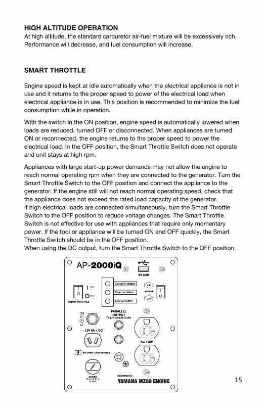
SMART THROTTLE
Engine speed is kept at idle automatically when the electrical appliance is not in use and it returns to the proper speed to power of the electrical load when electrical appliance is in use. This position is recommended to minimize the fuel consumption while in operation.
With the switch in the ON position, engine speed is automatically lowered when loads are reduced, turned OFF or disconnected. When appliances are turned ON or reconnected, the engine returns to the proper speed to power the electrical load. In the OFF position, the Smart Throttle Switch does not operate and unit stays at high rpm.
Appliances with large start-up power demands may not allow the engine to reach normal operating rpm when they are connected to the generator. Turn the Smart Throttle Switch to the OFF position and connect the appliance to the generator. If the engine still will not reach normal operating speed, check that the appliance does not exceed the rated load capacity of the generator. If high electrical loads are connected simultaneously, turn the Smart Throttle Switch to the OFF position to reduce voltage changes. The Smart Throttle Switch is not effective for use with appliances that require only momentary power. If the tool or appliance will be turned ON and OFF quickly, the Smart Throttle Switch should be in the OFF position. When using the DC output, turn the Smart Throttle Switch to the OFF position.
16
CAUTION:
If modifications are made to the carburetor for high altitude operation, at an altitude lower than the carburetor is jetted for may result in reduced performance, overheating, and serious engine damage caused by an excessively lean air/fuel mixture.
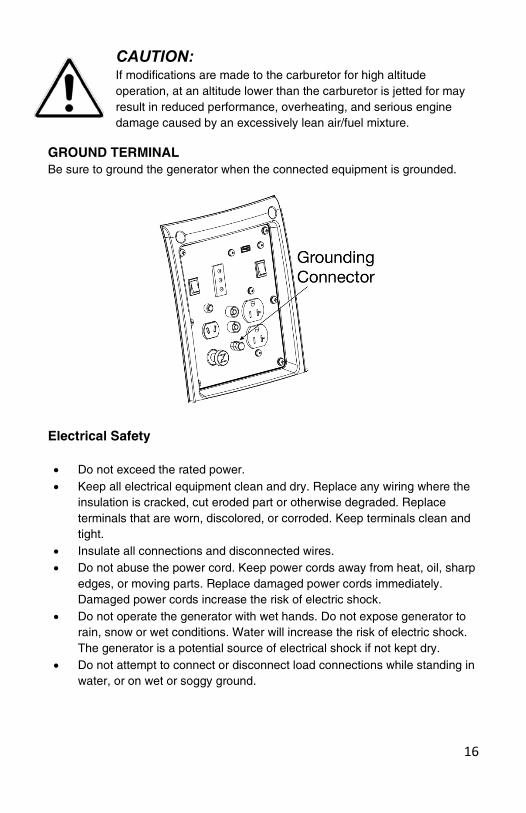
GROUND TERMINAL Be sure to ground the generator when the connected equipment is grounded.
Electrical Safety • Do not exceed the rated power. • Keep all electrical equipment clean and dry. Replace any wiring where the
insulation is cracked, cut eroded part or otherwise degraded. Replace terminals that are worn, discolored, or corroded. Keep terminals clean and tight.
• Insulate all connections and disconnected wires. • Do not abuse the power cord. Keep power cords away from heat, oil, sharp
edges, or moving parts. Replace damaged power cords immediately. Damaged power cords increase the risk of electric shock.
• Do not operate the generator with wet hands. Do not expose generator to rain, snow or wet conditions. Water will increase the risk of electric shock. The generator is a potential source of electrical shock if not kept dry.
• Do not attempt to connect or disconnect load connections while standing in water, or on wet or soggy ground.

17
Electrical Safety Continued • Do not touch electrically energized parts of the generator and
interconnecting cables or conductors with any part of the body, or with any non-insulated conductive object.
• Avoid body contact with grounded surfaces such as pipes, radiators, ranges, and refrigerators. There is an increased risk of electric shock if your body is grounded.
• When operating a power tool outside, use an outdoor extension cord marked “W-A” or “W”. These extension cords are rated for outdoor use, and reduce the risk of electric shock.
• Grounded tools must be plugged into an outlet properly installed and grounded in accordance with all codes and ordinances. Never remove the grounding prong or modify the plug in any way. Do not use any adapter plugs.
• Double insulated tools are equipped with a polarized plug where one blade is wider than the other. This plug fits in a polarized outlet only one way. If the plug does not fit fully in the outlet, reverse the plug. If it still does not fit, contact a qualified electrician to install a polarized outlet. Do not change the plug in any way. Double insulation eliminates the need for the three-wire grounded power cord and grounded power supply system.
• Before servicing equipment powered by the generator, disconnect the equipment from its power input.
• The generator must be earth-grounded for fixed installations in accordance with all relevant electrical codes and standards before operation.
• Grounding provides a low-resistance path to carry electricity away from the user in the event of an electrical malfunction.
• All connections and conduits from the generator to the load must only be installed by trained and licensed electricians and in compliance with all relevant local, state, and federal electrical codes and standards, and other regulations where applicable.
• Connect the generator only to a load or electrical system (110/120 volt) that is compatible with the electrical characteristics and rated capacities of the generator.
• NEVER try to power building or home wiring by plugging the generator into a wall outlet, a practice known as “backfeeding.” This is extremely dangerous and presents an electrocution risk to utility workers and neighbors served by the same utility transformer. It also bypasses some of the built-in household circuit protection devices.

18
AC APPLICATIONS 1. Start the engine and make sure the output indicator LED (green) flashes. 2. Confirm that the appliance to be used is switched off, and plug in the
appliance. 3. In order to acquire both the best effect and the maximum service life of the
generator, operate the generator for 20 hours under 50% load, so that the generator may reach the best performance.
NOTE: The DC receptacle can be used while the AC power is in use. If you use both at the same time, be sure not to exceed the total power for AC and DC.
Output and Overload Indicators The output indicator LED (green) will flash during normal operating conditions. If the generator is overloaded, or if there is a short in the connected appliance, the output indicate LED (green) will go OFF, the overload indicator LED (red) will go ON and current to the connected appliance will be shut off. Stop the engine if the overload indicator LED (red) comes ON and investigate the overload source
Note: Substantial overloading that continuously lights the overload indicator LED (red) may damage the generator. Marginal overloading that temporarily lights the overload indicator LED (red) may shorten the service life of the generator.
Before connecting an appliance to the generator, check that it is in good order, and that its electrical rating does not exceed that of the generator. Then start the engine, and connect the power cord of the appliance When an electric motor is started, both the overload indicator LED (red) and the output indicator LED (green) may go on simultaneously. This is normal if the overload indicator LED (red) goes off after about four (4) seconds. If the overload indicator LED (red) stays on, please contact Smarter Tools.

19
CONNECTING THE BATTERY CHARGING CABLE 1. Before connecting the battery charging cable to a battery that is installed in a
vehicle, disconnect the vehicle battery ground cable from the negative (-) battery terminal.
2. Connect the charging cables to the DC outlet of the generator and then to the battery terminals.
3. Connect the red lead of the battery charging cable to the positive (+) battery terminal and the black lead to the negative (-) battery terminal.
CAUTION: Do not attempt to start an automobile engine with the generator still connected to the battery. The generator may be damaged.
WARNING! To prevent the possibility of creating a spark near the battery, connect charging cable first to the genera- tor, then to the battery. Disconnect cable first at the battery. Before connecting charging cables to a battery that is installed in a vehicle, disconnect the vehicles grounded battery cable. Reconnect the vehicle’s grounded battery cable after the charging cables are removed. This procedure will prevent the possibility of a short circuit and sparks if you make accidental contact between a battery terminal and the vehicle’s frame or body.
CAUTION: Connect the positive battery terminal to the positive charging cord.
Do not reverse the charging cables, or serious damage to the generator and/or battery may occur

20
DC CIRCUIT BREAKER The DC circuit breaker automatically shuts off the DC battery charging circuit when the DC charging circuit is overloaded, when there is a problem with the battery, or when the connections between the battery and the generator are improper. Check before resetting the circuit breaker. NOTE: Check the cause reason after DC circuit breaker automatically shuts off. NOTE: Fix the problem before manual resetting the DC circuit breaker ON.
DISCONNECTING THE BATTERY CHARGING CABLE 1. Stop the engine. 2. Disconnect the black lead of the battery charging cable from the negative (-)
battery terminal. 3. Disconnect the red lead of the battery charging cable from the positive (+)
battery terminal. 4. Disconnect the battery charging cable from the DC receptacle of the
generator.
OIL ALERT SYSTEM The oil alert system is designed to prevent engine dam- age caused by an insufficient amount of oil in the crank- case. Before the oil level in the crankcase falls below a safe limit, the oil alert system will automatically shut down the engine (the fuel switch will remain in the ON position). If the oil alert system shuts down the engine, the oil alert indicator LED (yellow) will come on when you operate the starter, and the engine will not run. If this occurs, add engine oil.

21
Stopping the Engine To stop the engine in an emergency, turn the fuel switch and the Ignition switch to the OFF position. Stopping the Generator 1. Unplug cables. 2. Turn the fuel petcock to the OFF position. (Fig. 12A) 3. Turn the ignition switch to the OFF position. (Fig.12B)
Fig. 12A Fig. 12B
TRANSPORTING • Take care not to drop or strike the generator when transporting. Do not
place heavy objects on the generator. • To prevent a fuel spill when transporting, ensure that the fuel cap is on
and tight. The generator should be secured upright in its normal operating position with the fuel petcock OFF.
• If the generator has been used, allow it cool for at least 15 minutes before loading the generator on the transport vehicle. A hot engine and exhaust system can burn you and can ignite some material.
• Do not lay the generator on its side when moving, storing, or operating it. Oil and fuel may leak and damage the engine or your property.
OFF ON
22
Parallel Function
WARNING! Do not pair more than 2 generators. It is recommended to only use the Smarter Tools™ parallel output cable for parallel operation.
CAUTION: While operating in parallel, only use the parallel cable outlet. DO NOT use the outlet on the control panel of the generator while operating in parallel. It may cause an unbalanced output to the parallel connection which may result in damage to the generator(s).
CAUTION: DO NOT disconnect the parallel connection cable from the control panel while the generators are running. Turn off both generators before disconnecting parallel cables.
Before connecting an appliance to a generator, make sure that the appliance is in good working order and that its electrical rating does not exceed that of the outlet. Most appliances require more than their electrical rating for startup.
Connecting the Parallel Cable
1. Have both generators ready to operate. 2. Make sure all three Parallel connections on both control panels are
secure. (follow instructions with cable kit)
WARNING! If parallel cables are not properly connected to the generators, either or both generators can be damaged and could explode.
3. Start each generator and allow it to normalize running. 4. Connect only to the parallel outlet.
Note: The required power of the electrical appliance connected to the parallel outlet cannot exceed the rated output of paralleled generators. See specifications page in owner’s manual.
23
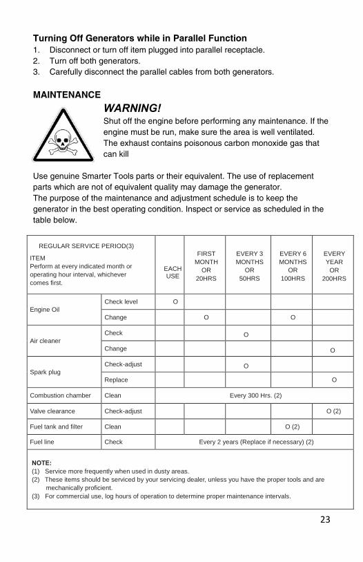
REGULAR SERVICE PERIOD(3) ITEM Perform at every indicated month or operating hour interval, whichever comes first.
EACH USE
FIRST MONTH
OR 20HRS
EVERY 3 MONTHS
OR 50HRS
EVERY 6 MONTHS
OR 100HRS
EVERY YEAR
OR 200HRS
Engine Oil
Check level O Change O
O Air cleaner
Check O Change O
Spark plug
Check-adjust O Replace O
Combustion chamber Clean Every 300 Hrs. (2)
Valve clearance Check-adjust O (2)
Fuel tank and filter Clean O (2) Fuel line Check Every 2 years (Replace if necessary) (2)
NOTE: (1) Service more frequently when used in dusty areas. (2) These items should be serviced by your servicing dealer, unless you have the proper tools and are
mechanically proficient. (3) For commercial use, log hours of operation to determine proper maintenance intervals.
Turning Off Generators while in Parallel Function 1. Disconnect or turn off item plugged into parallel receptacle. 2. Turn off both generators. 3. Carefully disconnect the parallel cables from both generators.
MAINTENANCE
WARNING! Shut off the engine before performing any maintenance. If the engine must be run, make sure the area is well ventilated. The exhaust contains poisonous carbon monoxide gas that can kill
Use genuine Smarter Tools parts or their equivalent. The use of replacement parts which are not of equivalent quality may damage the generator. The purpose of the maintenance and adjustment schedule is to keep the generator in the best operating condition. Inspect or service as scheduled in the table below.
24
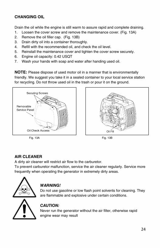
CHANGING OIL Drain the oil while the engine is still warm to assure rapid and complete draining. 1. Loosen the cover screw and remove the maintenance cover. (Fig. 13A) 2. Remove the oil filler cap. (Fig. 13B) 3. Drain dirty oil into a container thoroughly. 4. Refill with the recommended oil, and check the oil level. 5. Reinstall the maintenance cover and tighten the cover screw securely. 6. Engine oil capacity: 0.42 USQT 7. Wash your hands with soap and water after handing used oil.
NOTE: Please dispose of used motor oil in a manner that is environmentally friendly. We suggest you take it in a sealed container to your local service station for recycling. Do not throw used oil in the trash or pour it on the ground.
Fig. 13A Fig. 13B
AIR CLEANER A dirty air cleaner will restrict air flow to the carburetor. To prevent carburetor malfunction, service the air cleaner regularly. Service more frequently when operating the generator in extremely dirty areas.
WARNING! Do not use gasoline or low flash point solvents for cleaning. They are flammable and explosive under certain conditions.
CAUTION: Never run the generator without the air filter, otherwise rapid engine wear may result
25
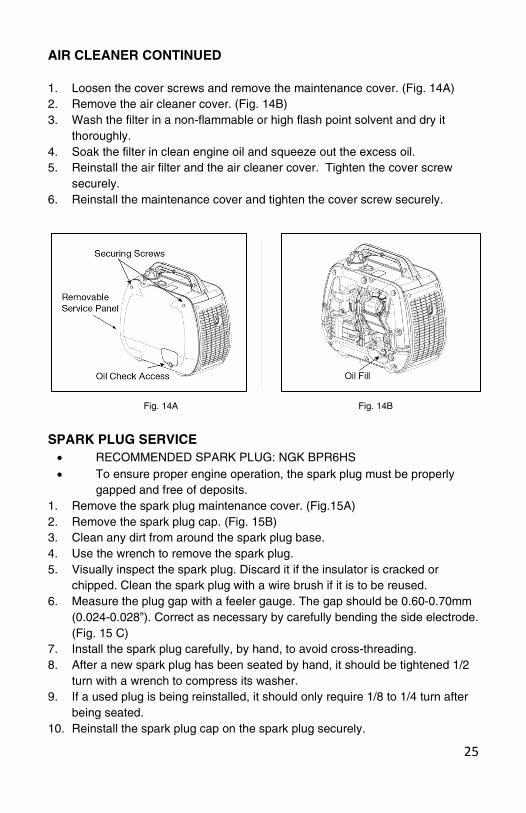
AIR CLEANER CONTINUED 1. Loosen the cover screws and remove the maintenance cover. (Fig. 14A) 2. Remove the air cleaner cover. (Fig. 14B) 3. Wash the filter in a non-flammable or high flash point solvent and dry it
thoroughly. 4. Soak the filter in clean engine oil and squeeze out the excess oil. 5. Reinstall the air filter and the air cleaner cover. Tighten the cover screw
securely. 6. Reinstall the maintenance cover and tighten the cover screw securely.
Fig. 14A Fig. 14B
SPARK PLUG SERVICE
• RECOMMENDED SPARK PLUG: NGK BPR6HS • To ensure proper engine operation, the spark plug must be properly
gapped and free of deposits. 1. Remove the spark plug maintenance cover. (Fig.15A) 2. Remove the spark plug cap. (Fig. 15B) 3. Clean any dirt from around the spark plug base. 4. Use the wrench to remove the spark plug. 5. Visually inspect the spark plug. Discard it if the insulator is cracked or
chipped. Clean the spark plug with a wire brush if it is to be reused. 6. Measure the plug gap with a feeler gauge. The gap should be 0.60-0.70mm
(0.024-0.028”). Correct as necessary by carefully bending the side electrode. (Fig. 15 C)
7. Install the spark plug carefully, by hand, to avoid cross-threading. 8. After a new spark plug has been seated by hand, it should be tightened 1/2
turn with a wrench to compress its washer. 9. If a used plug is being reinstalled, it should only require 1/8 to 1/4 turn after
being seated. 10. Reinstall the spark plug cap on the spark plug securely.

26
SPARK PLUG SERVICE CONTINUED
CAUTION: Make sure engine is cool before servicing or removing spark plug.
Fig. 15A Fig 15B
Fig 15C
Storing the Generator To prevent fuel spill when transporting or during temporary storage, the generator should be secured upright in its normal operating position, with the engine switch OFF.
Storing the unit 1. Be sure the storage area is free of excessive humidity and dust.
a. Keep heat, sparks, and flame away. b. Handle fuel only outdoors. c. Wipe up spills immediately. d. Keep out of reach of children and pets.

27
Storing the unit Continued
2. Drain the fuel. a. Drain all gasoline from the fuel tank into an approved gasoline container. b. Turn the petcock to ON, and loosen the carburetor drain screw and drain the gasoline from the carburetor into a suitable container.
c. When all the fuel is drained, turn the petcock to the OFF position, and tighten the drain screw securely.
3. Change the engine oil. 4. Remove the spark plug and pour about a table- spoon of clean engine
oil into the cylinder. Crank the engine several revolutions to distribute the oil, the reinstall the spark plug.
5. Reinstall the spark plug cap on the spark plug securely. 6. Reinstall the spark plug maintenance cover. 7. Reinstall the maintenance cover and tighten the cover screw securely. 8. Pull the starter grip slowly until resistance is felt, then return the starter
grip gently. This closes the values so moisture cannot enter.
Troubleshooting Engine will not Start: No Refuel the tank Is there fuel in the tank? Yes Is the fuel Petcock and No Turn the Petcock and engine ignition switched on? ignition switch ‘ON’ Yes Is there enough oil in No Add the recommended oil to the engine? proper level Yes Is there a spark from No Replace Still No Contact the spark plug? spark plug Spark for Service

28
WARNING! Be sure that is no spilled fuel around the spark plug. Spilled fuel may ignite.
To check:
1. Remove the spark plug cap and clean any dirt from around the spark plug
2. Remove the spark plug and install the spark plug in the plug cap. 3. Set the plug electrode on the cylinder head. 4. Pull the recoil starter; sparks should jump across the gap. 5. If the engine still does not start, contact Smarter Tools.
29

30
Parts diagram
31
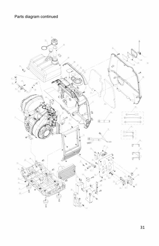
Parts diagram continued
32
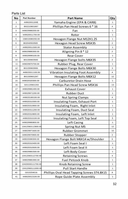
Parts List
No Part Number Part Name Qty1 44902001100E Yamaha Engine (EPA & CARB) 1
2 B02210601667 Phillips Pan Head Screws 6 * 16 4
3 449029980200.00 Fan 1
4 449020011700.00 Rotor 1
5 158010080200.00 Hexagon Flange Nut M12X1.25 1
6 B02040503565 Hexagon Head Screw M5X35 2
7 449020011500.00 Stator Assembly 1
8 449029880300.00 Aligning Pin 8 * 12 2
9 449029990100.00 Rear Cover 1
10 B01330603565 Hexagon Flange bolts M6X35 2
11 449029970700.00 Rubber Plug, Rear Cover 1
12 B01330603065 Hexagon Flange Bolts M6X30 3
13 449020011100.00 Vibration Insulating Foot Assembly 4
14 B01330601267 Hexagon Flange Bolts M6X12 12
15 449020320300.00 Carburetor Drain Hose 1
16 G01120501203 Phillips Pan Head Screw M5X16 13
17 449029981400.00 Exhaust Cover 1
18 449029971200.00 Rubber Duct 1
19 449020180100.00 Nut Spring Clamps 4
20 449020310300.00 Insulating Foam, Exhaust Port 1
21 449020310900.00 Insulating Foam, Right Inlet 1
22 449020311200.00 Insulating Foam, Duct Seal 1
23 449020310800.00 Insulating Foam, Left Inlet 1
24 449020310100.00 Insulating Foam, Left Top Seal 1
25 449029980800.00 Left Casing 1
26 10412060112800.00 Spring Nut M5 12
27 449029971600.00 Rubber Grommet 10
28 449029970900.00 Rubber Stopper 2
29 449020080300.00 Hexagon Flange Bolt M6X14 w/Shoulder 6
30 449020310400.00 Left Foam Seal I 1
31 449020310500.00 Left Foam Seal II 1
35 449029981500.00 Left Body Cover 1
36 10412060112700.00 Retaining Screws 4
37 449029981900.00 Fuel Petcock Knob 1
38 10420030111700.00 Knob Retaining Screw 1
39 10412060111000.00 Pull Start Handle 1
40 G010204016 Phillips Oval Head Tapping Screws ST4.8X15 8
41 449020013100.00 Rope Guide Plate Assembly 1
33
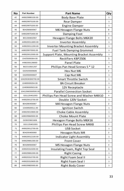
No Part Number Part Name Qty42 449029980100.00 Body Base Plate 1
43 449029970100.00 Rear Damper 1
44 449029970200.00 Engine Damper 1
45 B04280600067 M6 Hexagon Flange Nuts 8
47 449029970400.00 Damping Foot 4
48 B01330602067 Hexagon Flange Bolts M6X20 4
49 449020011800.00 Inverter Assembly 1
50 449020011200.00 Inverter Mounting Bracket Assembly 1
51 449029970500.00 Fuel Tank Damping Grommet 1
52 449020012000.00 Support Plate, Mounting Bracket Assembly 1
53 10425000304.00 Rectifiers KBP2506 1
55 449020012800D Panel Plate 1
56 B02210501267 Phillips Pan Head Screws 5 * 12 4
57 G02020000606 Hex Nut M6 2
58 G02050000607 Cap Nut M6 1
59 10420030300700.00 Smart Throttle Switch 1
60 10465000204.00 8A Circuit Breaker 1
61 10409000503.00 12V Receptacle 1
62 10412060300500.00 Parallel Connection Socket 2
63 G01120401003 Phillips Pan Head Screw and Washer M4X10 4
64 449020013700.00 Double 120V Socket 1
65 B04280400067 M4 Hexagon Flange Nuts 2
66 10409500511.00 Ignition Switch 1
67 449020010900.00 Choke Cable Assembly 1
68 449029960500.00 Choke Mount Plate 1
69 G03020601606 Hexagon Flange Bolts M6X16 1
70 G01120401003 Phillips Pan Head Screw M4X8 2
71 449020012700.00 USB Socket 1
72 B04200400060 Hexagon Nuts M4 2
73 449020012100.00 Indicator Light Assembly 1
74 449029981300.00 Front Cover 1
75 B04280500067 M5 Hexagon Flange Nuts 4
76 449020310200.00 Insulating Foam, Right Top Seal 1
77 449029981000.00 Right Casing 1
78 449020310700.00 Right Foam Seal II 1
79 449020310600.00 Right Foam Seal I 1
80 449029982000.00 Right Body Cover 1
34
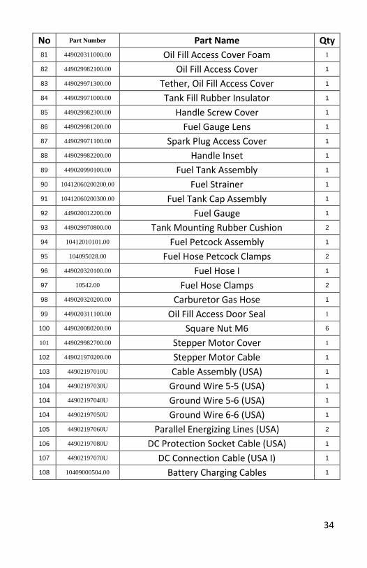
No Part Number Part Name Qty 81 449020311000.00 Oil Fill Access Cover Foam 1
82 449029982100.00 Oil Fill Access Cover 1
83 449029971300.00 Tether, Oil Fill Access Cover 1
84 449029971000.00 Tank Fill Rubber Insulator 1
85 449029982300.00 Handle Screw Cover 1
86 449029981200.00 Fuel Gauge Lens 1
87 449029971100.00 Spark Plug Access Cover 1
88 449029982200.00 Handle Inset 1
89 449020990100.00 Fuel Tank Assembly 1
90 10412060200200.00 Fuel Strainer 1
91 10412060200300.00 Fuel Tank Cap Assembly 1
92 449020012200.00 Fuel Gauge 1
93 449029970800.00 Tank Mounting Rubber Cushion 2
94 10412010101.00 Fuel Petcock Assembly 1
95 104095028.00 Fuel Hose Petcock Clamps 2
96 449020320100.00 Fuel Hose I 1
97 10542.00 Fuel Hose Clamps 2
98 449020320200.00 Carburetor Gas Hose 1
99 449020311100.00 Oil Fill Access Door Seal 1
100 449020080200.00 Square Nut M6 6
101 449029982700.00 Stepper Motor Cover 1
102 449021970200.00 Stepper Motor Cable 1
103 44902197010U Cable Assembly (USA) 1
104 44902197030U Ground Wire 5-5 (USA) 1
104 44902197040U Ground Wire 5-6 (USA) 1
104 44902197050U Ground Wire 6-6 (USA) 1
105 44902197060U Parallel Energizing Lines (USA) 2
106 44902197080U DC Protection Socket Cable (USA) 1
107 44902197070U DC Connection Cable (USA I) 1
108 10409000504.00 Battery Charging Cables 1

35
LIMITED WARRANTY __________________________________________________________ Effective September 1, 2013. Replaces all undated warranties and all warranties dated before September 1, 2013 Warranty Qualifications Smarter Tools will register this warranty upon receipt of your Warranty Registration Card and a copy of your sales receipt from one of Smarter Tools' retail locations as proof of purchase. Please submit your warranty registration and your proof of purchase within fourteen (14) days of the date of purchase. Repair/Replacement Warranty Smarter Tools warrants to the original purchaser that the mechanical and electrical components will be free of defects in material and workmanship for a period of three (3) years from the original date of purchase (90 days for commercial & industrial use). Transportation charges on product submitted for repair or replacement under this warranty are the sole responsibility of the purchaser. This workmanship for a period of warranty only applies to the original purchaser and is not transferable. Do not return the unit to the place of purchase Contact Smarter Tools’ Customer Service and Smarter Tools will troubleshoot any issue via phone or e-mail. If the problem is not corrected by this method, Smarter Tools will, at its option, authorize evaluation, repair or replacement of the defective part or component at a Smarter Tools Service Center. Smarter Tools will provide you with a case number for warranty service. Please keep it for future reference. Repairs or replacements without prior authorization, or at an unauthorized repair facility, will not be covered. Warranty Exclusions This warranty does not cover the following repairs and equipment: Normal Wear Generators need periodic parts and service to perform well. This warranty does not cover repair when normal use has exhausted the life of a part or the equipment as a whole. Installation, Use and Maintenance This warranty will not apply to parts and/or labor if this generator is deemed to have been misused, neglected, involved in an accident, abused, loaded beyond the generator's limits, modified, installed improperly or connected incorrectly to any electrical component. Normal maintenance such as spark plugs, air filters, adjustments, fuel system cleaning and obstruction due to buildup is not covered by this warranty.

36
LIMITED Warranty (continued) __________________________________________________________ Other Exclusions This warranty excludes:
• Merchandise sold as reconditioned, used as rental equipment, or floor/display models sold without packaging and/or missing parts or components.
• Repair and transportation costs of merchandise determined not to be defective.
• Cosmetic defects such as paint, decals, etc.
• Wear items such as filter elements, o-rings, etc.
• Accessory parts such as starting batteries, and storage covers.
• Failures due to acts of God and other forces of nature beyond the manufacturer's control.
• Problems caused by parts that are not original Smarter Tools parts.
This warranty does not apply to generators used for prime power in place of a utility. Limits of Implied Warranty and Consequential Damage Smarter Tools disclaims any obligation to cover any loss of time, use of this product, freight, or any incidental or consequential claim by anyone from using this generator. THIS WARRANTY IS IN LIEU OF ALL OTHER WARRANTIES, EXPRESS OR IMPLIED, INCLUDING WARRANTIES OF MERCHANTABILITY OR FITNESS FOR A PARTICULAR PURPOSE. A unit provided as an exchange will be subject to the warranty of the original unit. The length of the warranty governing the exchanged unit will remain calculated by reference to the purchase date of the original unit. This warranty gives you certain legal rights which may change from state to state. Your state may also have other rights you may be entitled to that are not listed within this warranty. Some states do not allow the exclusion, so it may not apply to you. Contact us at: Smarter Tools Customer Service 12195 Harley Club Drive Ashland, VA 23005 (888)241-8498 [email protected]
37
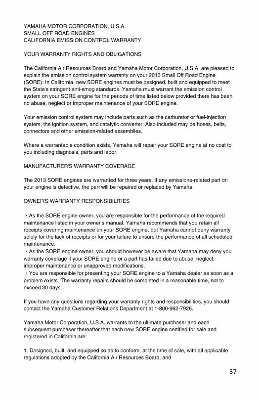
YAMAHA MOTOR CORPORATION, U.S.A. SMALL OFF ROAD ENGINES CALIFORNIA EMISSION CONTROL WARRANTY YOUR WARRANTY RIGHTS AND OBLIGATIONS The California Air Resources Board and Yamaha Motor Corporation, U.S.A. are pleased to explain the emission control system warranty on your 2013 Small Off Road Engine (SORE). In California, new SORE engines must be designed, built and equipped to meet the State's stringent anti-smog standards. Yamaha must warrant the emission control system on your SORE engine for the periods of time listed below provided there has been no abuse, neglect or improper maintenance of your SORE engine. Your emission control system may include parts such as the carburetor or fuel-injection system, the ignition system, and catalytic converter. Also included may be hoses, belts, connectors and other emission-related assemblies. Where a warrantable condition exists, Yamaha will repair your SORE engine at no cost to you including diagnosis, parts and labor. MANUFACTURER'S WARRANTY COVERAGE The 2013 SORE engines are warranted for three years. If any emissions-related part on your engine is defective, the part will be repaired or replaced by Yamaha. OWNER'S WARRANTY RESPONSIBILITIES ・As the SORE engine owner, you are responsible for the performance of the required maintenance listed in your owner's manual. Yamaha recommends that you retain all receipts covering maintenance on your SORE engine, but Yamaha cannot deny warranty solely for the lack of receipts or for your failure to ensure the performance of all scheduled maintenance. ・As the SORE engine owner, you should however be aware that Yamaha may deny you warranty coverage if your SORE engine or a part has failed due to abuse, neglect, improper maintenance or unapproved modifications. ・You are responsible for presenting your SORE engine to a Yamaha dealer as soon as a problem exists. The warranty repairs should be completed in a reasonable time, not to exceed 30 days. If you have any questions regarding your warranty rights and responsibilities, you should contact the Yamaha Customer Relations Department at 1-800-962-7926. Yamaha Motor Corporation, U.S.A. warrants to the ultimate purchaser and each subsequent purchaser thereafter that each new SORE engine certified for sale and registered in California are: 1. Designed, built, and equipped so as to conform, at the time of sale, with all applicable regulations adopted by the California Air Resources Board, and
38
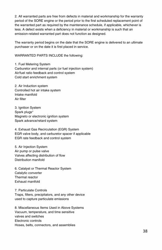
2. All warranted parts are free from defects in material and workmanship for the warranty period of the SORE engine or the period prior to the first scheduled replacement point of the warranted part as required by the maintenance schedule, if applicable, whichever is less. A defect exists when a deficiency in material or workmanship is such that an emission-related warranted part does not function as designed. The warranty period begins on the date that the SORE engine is delivered to an ultimate purchaser or on the date it is first placed in service. WARRANTED PARTS INCLUDE the following: 1. Fuel Metering System Carburetor and internal parts (or fuel injection system) Air/fuel ratio feedback and control system Cold start enrichment system 2. Air Induction system Controlled hot air intake system Intake manifold Air filter 3. Ignition System Spark plugs* Magneto or electronic ignition system Spark advance/retard system 4. Exhaust Gas Recirculation (EGR) System EGR valve body, and carburetor spacer if applicable EGR rate feedback and control system 5. Air Injection System Air pump or pulse valve Valves affecting distribution of flow Distribution manifold 6. Catalyst or Thermal Reactor System Catalytic converter Thermal reactor Exhaust manifold 7. Particulate Controls Traps, filters, precipitators, and any other device used to capture particulate emissions 8. Miscellaneous Items Used in Above Systems Vacuum, temperature, and time sensitive valves and switches Electronic controls Hoses, belts, connectors, and assemblies

39
9. Engine components damaged due to a failure under warranty or a warranted part *The original spark plug(s) are warranted for the period of replacement indicated in the Owner's Manual and not the useful life of the SORE engine (see your Owner's Manual). DURING THE PERIOD OF THIS WARRANTY Yamaha Motor Corporation, U.S.A. will repair or replace any warranted part deemed defective by Yamaha during the scope of the warranty without charge to the owner, including parts, labor, and diagnosis. This work must be done at an authorized Yamaha dealer. Give notice to an authorized Yamaha dealer of any apparent defects(s) within a reasonable period of time after discovery. The SORE engine must be made available for inspection by an authorized Yamaha dealer. OWNER'S RESPONSIBILITY: The owner of the SORE engine is responsible for the performance of required maintenance (see your Owner's Manual). Receipts and maintenance records covering the performance of regular maintenance should be retained in the event questions arise concerning maintenance. The receipts should be transferred to each subsequent owner of this SORE engine. The emission control systems of your Yamaha SORE engine were designed, built, tested, and certified as being in conformity with California emission control regulations using genuine Yamaha parts. Accordingly, it is recommended that any replacement part(s) used for maintenance, replacement, or repair of emission control systems be Yamaha parts. The owner may elect to have maintenance, replacement, or repair of the emission control devices and systems performed by any repair establishment or individual, and may elect to use parts other than Yamaha parts for such maintenance, replacement, or repair without invalidating this warranty. However, the cost of such service or parts will not be covered under the warranty. EXCLUSIONS: No warranty coverage will be allowed if the part(s) failure was caused by owner/operator abuse, neglect, tampering, improper adjustment unless performed by a dealer during warranty repair work, modification, misuse, alteration, or improper maintenance (see your Owner's Manual). Use of parts which are not qualitatively equivalent to genuine Yamaha parts, improper service, or lack of required maintenance which causes failure of a warranted part may constitute abuse and/or improper service, thereby invalidating warranty liability hereunder. This warranty does not cover damage resulting from accidents, acts of nature, or other events or occurrences beyond the control of Yamaha. Yamaha Motor Corporation, U.S.A. expressly disclaims responsibility for any and all consequential damages, such as loss of time, inconvenience, loss or use of the SORE engine, or commercial loss. YAMAHA MOTOR CORPORATION, U.S.A. Post Office Box 6555 Cypress, California 90630

40
CALIFORNIA EMISSIONS CONTROL WARRANTY STATEMENT YOUR WARRANTY RIGHTS AND OBLIGATIONS The California Air Resources Board and Smarter Tools, Inc. are pleased to explain the emissions control system warranty on your 2013 small off-road equipment (EQUIPMENT). In California, new EQUIPMENT must be designed, built and equipped to meet the State's stringent anti-smog standards. Smarter Tools, Inc. must warrant the emissions control system on your EQUIPMENT for the periods of time listed below provided there has been no abuse, neglect or improper maintenance of your EQUIPMENT. Your evaporative emission control system may include parts such as: carburetors, fuel tanks, fuel lines, fuel caps, valves, canisters, filters, vapor hoses, clamps, connectors, and other associated components. For engines less than or equal to 80cc, only the fuel tank is subject to the evaporative emission control warranty requirements of this section (California only). Where a warrantable condition exists, Smarter Tools, Inc. will repair your small off-road equipment (EQUIPMENT) at no cost to you including diagnosis, parts and labor. MANUFACTURER'S WARRANTY COVERAGE: The emissions control system is warranted for two years. If any emissions-related part on your EQUIPMENT is defective, the part will be repaired or replaced by Smarter Tools, Inc. OWNER'S WARRANTY RESPONSIBILITIES:
-As the EQUIPMENT owner, you are responsible for the performance of the required maintenance listed in your owner's manual. Smarter Tools, Inc. recommends that you retain all receipts covering maintenance on your EQUIPMENT, but Smarter Tools, Inc. can not deny warranty solely for the lack of receipts or for your failure to ensure the performance of all scheduled maintenance. -As the EQUIPMENT owner, you should however be aware that Smarter Tools, Inc. may deny your warranty coverage if your EQUIPMENT or a part has failed due to abuse, neglect, improper maintenance or unapproved modifications. -You are responsible for presenting your EQUIPMENT to distribution center or service center authorized by Smarter Tools, Inc. as soon as the problem exists. The warranty repairs should be completed in a reasonable amount of time, not to exceed 30 days.
If you have any questions regarding your warranty coverage, you should contact Smarter Tools, Inc. customer service representative at 1-888-241-8498 or [email protected].
41
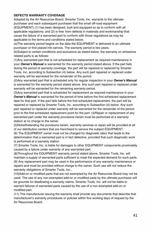
DEFECTS WARRANTY COVERAGE Adopted by the Air Resources Board, Smarter Tools, Inc. warrants to the ultimate purchaser and each subsequent purchaser that the small off-road equipment (EQUIPMENT) (1) has been designed, built and equipped so as to conform with all applicable regulations; and (2) is free from defects in materials and workmanship that cause the failure of a warranted part to conform with those regulations as may be applicable to the terms and conditions stated below. (a)The warranty period begins on the date the EQUIPMENT is delivered to an ultimate purchaser or first placed into service. The warranty period is two years. (b)Subject to certain conditions and exclusions as stated below, the warranty on emissions related parts is as follows: (1)Any warranted part that is not scheduled for replacement as required maintenance in your Owner’s Manual is warranted for the warranty period stated above. If the part fails during the period of warranty coverage, the part will be repaired or replaced by Smarter Tools, Inc. according to Subsection (4) below. Any such part repaired or replaced under warranty will be warranted for the remainder of the period. (2)Any warranted part that is scheduled only for regular inspection in your Owner’s Manual is warranted for the warranty period stated above. Any such part repaired or replaced under warranty will be warranted for the remaining warranty period. (3)Any warranted part that is scheduled for replacement as required maintenance in your Owner’s Manual is warranted for the period of time before the first scheduled replacement date for that part. If the part fails before the first scheduled replacement, the part will be repaired or replaced by Smarter Tools, Inc. according to Subsection (4) below. Any such part repaired or replaced under warranty will be warranted for the remainder of the period prior to the first scheduled replacement point for the part. (4)Repair or replacement of any warranted part under the warranty provisions herein must be performed at a warranty station at no charge to the owner. (5)Notwithstanding the provisions herein, warranty services or repair will be provided at all of our distribution centers that are franchised to service the subject EQUIPMENT. (6) The EQUIPMENT owner must not be charged for diagnostic labor that leads to the determination that a warranted part is in fact defective, provided that such diagnostic work is performed at a warranty station. (7) Smarter Tools, Inc. is liable for damages to other EQUIPMENT components proximately caused by a failure under warranty of any warranted part. (8)Throughout the EQUIPMENT warranty period stated above, Smarter Tools, Inc. will maintain a supply of warranted parts sufficient to meet the expected demand for such parts. (9) Any replacement part may be used in the performance of any warranty maintenance or repairs and must be provided without charge to the owner. Such use will not reduce the warranty obligations of Smarter Tools, Inc.. (10)Add-on or modified parts that are not exempted by the Air Resources Board may not be used. The use of any non-exempted add-on or modified parts by the ultimate purchaser will be grounds for disallowing a warranty claims. Smarter Tools, Inc. will not be liable to warrant failures of warranted parts caused by the use of a non-exempted add-on or modified part. (11) The manufacturer issuing the warranty shall provide any documents that describe that manufacturer's warranty procedures or policies within five working days of request by the Air Resources Board.

42
EMISSION WARRANTY PARTS LIST The repair or replacement of any warranted part otherwise eligible for warranty coverage may be excluded from such warranty coverage if Smarter Tools, Inc. demonstrates that the EQUIPMENT has been abused, neglected, or improperly maintained, and that such abuse, neglect, or improper maintenance was the direct cause of the need for repair or replacement of the part. That notwithstanding, any adjustment of a component that has a factory installed, and properly operating, adjustment limiting device is still eligible for warranty coverage. The following emissions warranty parts for each engine family list is covered. Evaporative families less than or equal to 80cc (1) Fuel tank evaporative emissions control system including: (a) Fuel Cap (b) Fuel Tank

41
English

31
Español
30
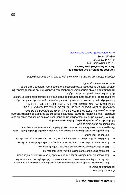
GARANTÍA LIMITADA (seguido) ________________________________________________________________________ Otras exclusiones Esta garantía excluye:
• La mercadería vendida como reacondicionados, usados como alquiler de equipos, o de piso / display modelos vendidos sin envase y / o falta de piezas o componentes.
• Los costos de reparación y transporte de mercadería determinada no defectuosa.
• Defectos cosméticos tales como pintura, calcomanías, etc.
• Utilice elementos como elementos filtrantes, juntas tóricas, etc.
• Los accesorios tales como baterías de arranque y cubiertas de almacenamiento.
• Los fallos debidos a hechos fortuitos ya otras fuerzas de la naturaleza más allá del control del fabricante.
• Los problemas causados por las piezas que no sean originales Smarter Tools Piezas. Esta garantía no se aplica a los generadores utilizados para suministrar energía en sustitución de un servicio público. Límites de la garantía implícita y daños consecuentes Smarter Tools se exime de toda obligación de cubrir toda pérdida de tiempo, el uso de este producto, flete, o cualquier reclamo incidental o consecuente por parte de cualquier usuario de este generador. ESTA GARANTÍA ES EN LUGAR DE TODAS LAS OTRAS GARANTÍAS, EXPRESAS O IMPLÍCITAS, INCLUYENDO LAS GARANTÍAS DE COMERCIALIZACIÓN O IDONEIDAD PARA UN PROPÓSITO PARTICULAR. La unidad proporcionada en intercambio quedará sujeto a la garantía de la unidad original. La duración de la garantía para la unidad de intercambio se seguirá calculando en función de la fecha de compra de la unidad original. Esta garantía le otorga ciertos derechos legales que pueden variar de estado a estado. Su estado también puede tener otros derechos que puedan tener derecho a que no se mencionan en esta garantía. Algunos estados no permiten la exclusión, por lo que no se apliquen a usted. Póngase en contacto con nosotros en: Smarter Tools Customer Service 12195 Harley Club Drive Ashland, VA 23005 (888)241-8498 [email protected]

29
GARANTÍA LIMITADA __________________________________________________________ 1 ° de septiembre de 2013. Sustituye a todas las garantías sin fecha ya las de fecha anterior garantías 01 de septiembre 2013 Requisitos de garantía Smarter Tools registrará esta garantía una vez que reciba su tarjeta de inscripción de garantía y una copia de su recibo de compra de una de las más elegantes tiendas minoristas Herramientas 'como prueba de compra. Envíe su registro de garantía y el comprobante de compra dentro de los catorce (14) días de la fecha de compra. Reparación / reemplazo Smarter Tools garantiza al comprador original que los componentes mecánicos y eléctricos estén libres de defectos en materiales y mano de obra por un período de tres (3) años a partir de la fecha original de compra (90 días para uso comercial e industrial). Los gastos de transporte de las producto enviadas para su reparación o reemplazo bajo esta garantía son responsabilidad del comprador. Esta mano de obra durante un período de garantía sólo se aplica al comprador original y no es transferible. No devuelva la unidad al lugar de compra Contacte con Smarter Tools "Servicio al cliente y más inteligente Tools solucionar cualquier problema por teléfono o e-mail. Si el problema no se corrige mediante este método, Smarter Tools, a su criterio, autorizará la evaluación, reparación o reemplazo de la parte o componente defectuoso en un centro de servicio más inteligente Herramientas. Smarter Tools le proporcionará un número de caso para el servicio de garantía. Por favor consérvelo para consultarlo en el futuro. Las reparaciones o reemplazos no autorizados, o en una instalación de reparación autorizada, no será cubierto. Exclusiones de la garantía Esta garantía no cubre las reparaciones y equipos siguientes: Desgaste normal Los generadores necesitan piezas y mantenimiento periódicos para funcionar bien. Esta garantía no cubre las reparaciones cuando el uso normal haya agotado la vida útil de una parte o del equipo en su conjunto. Instalación, uso y mantenimiento Esta garantía no se aplicará a las partes y / o mano de obra si este generador se considera que ha sido utilizado incorrectamente, maltratado, involucrado en un accidente, abuso, cargado más allá del generador, modificados o instalados, o conectado incorrectamente a algún componente eléctrico. El mantenimiento normal tales como cambio de bujías, filtros de aire, ajustes, limpieza del sistema de combustible y obstrucción debido a la acumulación no está cubierto por esta garantía.

28
Advertencia: Asegúrese de que no hay combustible derramado alrededor de la bujía. El combustible derramado puede encenderse.
Para comprobar:
1. Retire la tapa de la bujía y limpiar la suciedad alrededor de la bujía 2. Retire la bujía y montar la bujía en el capuchón de bujía. 3. Ajuste el electrodo enchufe en la culata. 4. Tire del arrancador de retroceso, chispas deben saltar a través de la brecha. 5. Si el motor sigue sin arrancar, póngase en contacto con Smarter Tools.
27
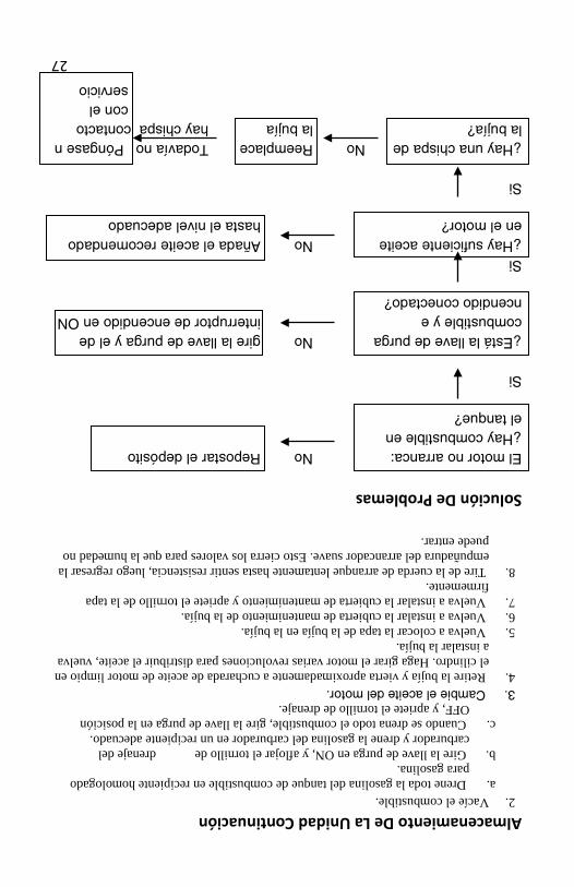
Almacenamiento De La Unidad Continuación 2. Vacíe el combustible.
a. Drene toda la gasolina del tanque de combustible en recipiente homologado para gasolina.
b. Gire la llave de purga en ON, y aflojar el tornillo de drenaje del carburador y drene la gasolina del carburador en un recipiente adecuado.
c. Cuando se drena todo el combustible, gire la llave de purga en la posición OFF, y apriete el tornillo de drenaje.
3. Cambie el aceite del motor. 4. Retire la bujía y vierta aproximadamente a cucharada de aceite de motor limpio en
el cilindro. Haga girar el motor varias revoluciones para distribuir el aceite, vuelva a instalar la bujía.
5. Vuelva a colocar la tapa de la bujía en la bujía. 6. Vuelva a instalar la cubierta de mantenimiento de la bujía. 7. Vuelva a instalar la cubierta de mantenimiento y apriete el tornillo de la tapa
firmemente. 8. Tire de la cuerda de arranque lentamente hasta sentir resistencia, luego regresar la
empuñadura del arrancador suave. Esto cierra los valores para que la humedad no puede entrar.
Solución De Problemas El motor no arranca: No Repostar el depósito ¿Hay combustible en el tanque? Si ¿Está la llave de purga No gire la llave de purga y el de combustible y e interruptor de encendido en ON ncendido conectado? Si ¿Hay suficiente aceite No Añada el aceite recomendado en el motor? hasta el nivel adecuado Si ¿Hay una chispa de No Reemplace Todavía no Póngase n la bujía? la bujía hay chispa contacto con el servicio
26
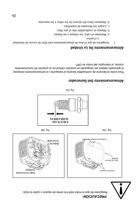
PRECAUCIÓN: Asegúrese de que el motor esté frío antes de reparar o quitar la bujía.
Fig. 15A Fig 15B
Fig 15C
Almacenamiento Del Generador Para evitar el derrame de combustible durante el transporte o el almacenamiento temporal, el generador deberá ser asegurado en posición vertical en su posición de funcionamiento normal, el interruptor del motor en OFF.
Almacenamiento De La Unidad 1. Asegúrese de que el área de almacenamiento esté libre de exceso de humedad
y el polvo. a. Mantener el calor, las chispas y las llamas. b. Maneje el combustible sólo al aire libre. c. Limpie los derrames de inmediato. d. Mantener fuera del alcance de los niños y las mascotas.

25
Filtro De Aire Continúa 1. Afloje los tornillos de la cubierta y retire la cubierta de mantenimiento. (Fig.14A)
2. Retire la tapa del filtro de aire. (Fig. 14B) 3. Lave el filtro con un punto de inflamación no inflamable o de alto solvente y
séquela bien. 4. Remoje el filtro en aceite de motor limpio y exprima el exceso de aceite.
5. Vuelva a instalar el filtro de aire y la cubierta del filtro de aire. Apriete el tornillo de la tapa firmemente.
6. Vuelva a instalar la cubierta de mantenimiento y apriete el tornillo de la tapa firmemente.
Fig. 14A Fig. 14B
Spark Servicio Enchufe • RECOMENDADOS Bujía: NGK BPR6HS • Para garantizar el funcionamiento adecuado del motor , la bujía debe tener la luz
correcta y libre de depósitos. 1. Quite la cubierta de mantenimiento de la bujía. ( Figura 15A ) 2. Retire el capuchón de la bujía . (Figura 15B ) 3. Limpie la suciedad alrededor de la base de la bujía . 4. Utilice la llave para quitar la bujía. 5. Inspeccione visualmente la bujía. Desechar si el aislante está agrietado o
astillado . Limpie la bujía con un cepillo de alambre si se va a reutilizar . 6. Mida la distancia entre electrodos con una galga de espesores . La distancia
debe ser de 0.60 - 0.70 mm ( 0,024-0,028 "). Corrija según sea necesario , doblando con cuidado el electrodo lateral. (Fig. 15 C)
7. Instale con cuidado la bujía , con la mano, para evitar que la rosca . 8. Después de una bujía nueva se ha sentado al lado, debe apretarse 1/2 vuelta
con una llave para comprimir la arandela. Si se vuelve a instalar un tapón utilizado, sólo debería requerir de 1/8 a 1/ 4 de vuelta después de estar sentados.
9. Vuelva a colocar la tapa de la bujía en la bujía.
24
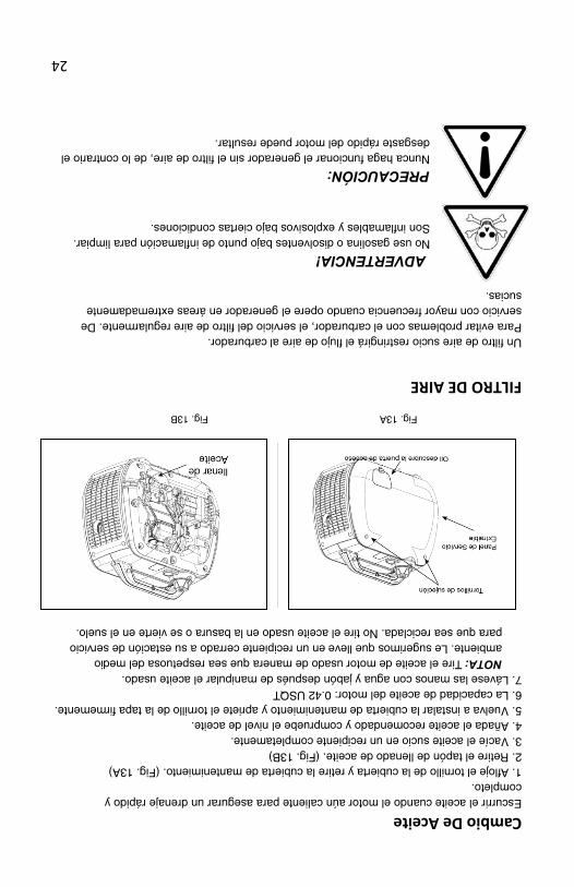
Cambio De Aceite Escurrir el aceite cuando el motor aún caliente para asegurar un drenaje rápido y completo. 1. Afloje el tornillo de la cubierta y retire la cubierta de mantenimiento. (Fig. 13A) 2. Retire el tapón de llenado de aceite. (Fig. 13B) 3. Vacíe el aceite sucio en un recipiente completamente. 4. Añada el aceite recomendado y compruebe el nivel de aceite. 5. Vuelva a instalar la cubierta de mantenimiento y apriete el tornillo de la tapa firmemente. 6. La capacidad de aceite del motor: 0.42 USQT 7. Lávese las manos con agua y jabón después de manipular el aceite usado.
NOTA: Tire el aceite de motor usado de manera que sea respetuosa del medio ambiente. Le sugerimos que lleve en un recipiente cerrado a su estación de servicio para que sea reciclada. No tire el aceite usado en la basura o se vierte en el suelo.
Fig. 13A Fig. 13B
FILTRO DE AIRE Un filtro de aire sucio restringirá el flujo de aire al carburador. Para evitar problemas con el carburador, el servicio del filtro de aire regularmente. De servicio con mayor frecuencia cuando opere el generador en áreas extremadamente sucias.
ADVERTENCIA! No use gasolina o disolventes bajo punto de inflamación para limpiar. Son inflamables y explosivos bajo ciertas condiciones.
PRECAUCIÓN: Nunca haga funcionar el generador sin el filtro de aire, de lo contrario el desgaste rápido del motor puede resultar.
23
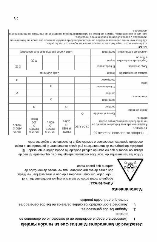
PERÍODO DE SERVICIO REGULAR (3) ARTÍCULO Realizar en cada mes indicado o intervalo de horas de funcionamiento, lo que ocurra primero.
CADA USO
PRIMER MES
O 20hrs
CADA 3 MESES
O 50hrs
CADA 6 MESES
O 100
horas
CADA AÑO O 200hrs
aceite del motor
Revise el nivel de
O cambiar O O
filtro de aire
comprobar O cambiar
O bujía
Entrada ajustar
O reemplazar O
cámara de combustión
limpiar
Cada 300 horas
Juego de válvulas
Entrada ajustar
O (2)
Depósito de combustible y filtro de
limpiar
O (2)
La línea de combustible
comprobar
Cada 2 años (Reemplazar si es necesario)
NOTA: (1) de servicio con mayor frecuencia cuando se usa en lugares con mucho polvo. (2) Estos elementos deben ser revisados por el concesionario de servicio, a menos que tenga las herramientas adecuadas y posea suficientes conocimientos mecánicos. (3) Para el uso comercial, registre las horas de funcionamiento para determinar los intervalos de mantenimiento adecuados.
Desactivación Generadores Mientras Que En Función Paralela 1. Desconecte o apague enchufado en el receptáculo de elementos en
paralelo. 2. Apague los dos generadores. 3. Desconecte con cuidado los cables paralelos de los dos generadores.
entras que en función paralela.
Mantenimiento Advertencia: Apague el motor antes de realizar cualquier mantenimiento. Si el motor debe funcionar, asegúrese de que el área esté bien ventilada. Los gases de escape contienen gas venenoso de monóxido de carbono que puede matar
Utilice las herramientas de recambios originales, inteligentes o su equivalente. El uso de piezas de repuesto que no sean de calidad equivalente podría dañar el generador. El propósito del programa de mantenimiento y el ajuste es mantener el generador en la mejor condición operativa. Inspeccione o servicio según lo previsto en la siguiente tabla.
22
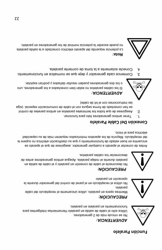
Función Paralelo ADVERTENCIA: No se vincule más de 2 generadores. Utilice sólo el cable de salida en paralelo Herramientas inteligentes para funcionamiento en paralelo en paralelo.
PRECAUCIÓN: Mientras opera en paralelo, utilice únicamente el receptáculo del cable paralelo. No utilice el receptáculo en el panel de control del generador durante la operación en paralelo
PRECAUCIÓN: No desconecte el cable de conexión en paralelo y el cable de salida en paralelo durante el rodaje paralela. Apague ambos generadores antes de
desconectar los cables paralelos.
Antes de conectar el aparato a cualquier generador, asegúrese de que el aparato se encuentra en buen estado de funcionamiento y que su clasificación eléctrica no supere la del receptáculo. Mayoría de los aparatos motorizados requieren más de su capacidad eléctrica para el inicio.
Conexión Del Cable Paralelo 1. Tener ambos generadores listo para funcionar. 2. Asegúrese de que todos los terminales paralelos en ambos paneles de control
se han conectado de forma segura con el cable de comunicación especial. (siga las instrucciones con el kit de cable)
ADVERTENCIA: Si los cables paralelos no están bien conectados a los generadores, uno
o los dos generadores pueden resultar dañados y podrían explotar.
3. Comience cada generador y deje que se normalice en funcionamiento. 4. Conecte solamente a la toma de corriente paralela.
Nota: La potencia requerida del aparato eléctrico conectado a la salida paralela no puede exceder la potencia nominal de los generadores en paralelo.
21
Parada Del Motor Para parar el motor en caso de emergencia, apague el interruptor de combustible y el
interruptor de encendido a la posición OFF.
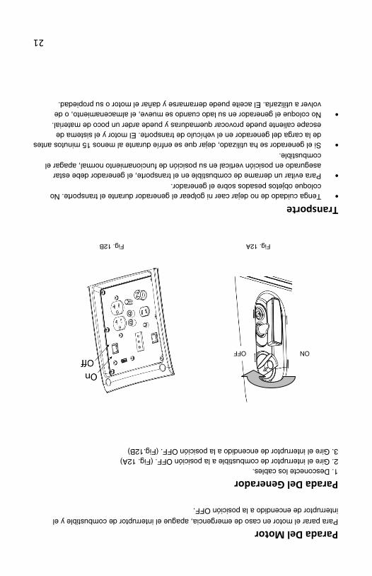
Parada Del Generador 1. Desconecte los cables. 2. Gire el interruptor de combustible a la posición OFF. (Fig. 12A) 3. Gire el interruptor de encendido a la posición OFF. (Fig.12B)
Fig. 12A Fig. 12B
Transporte • Tenga cuidado de no dejar caer ni golpear el generador durante el transporte. No
coloque objetos pesados sobre el generador. • Para evitar un derrame de combustible en el transporte, el generador debe estar
asegurado en posición vertical en su posición de funcionamiento normal, apagar el combustible.
• Si el generador se ha utilizado, dejar que se enfríe durante al menos 15 minutos antes de la carga del generador en el vehículo de transporte. El motor y el sistema de escape caliente puede provocar quemaduras y puede arder un poco de material.
• No coloque el generador en su lado cuando se mueve, el almacenamiento, o de volver a utilizarla. El aceite puede derramarse y dañar el motor o su propiedad.
OFF ON

20
DC Interruptor El circuito de potencia de CC se apaga automáticamente el circuito de carga de la batería de CC cuando se sobrecarga el circuito de carga CC, cuando hay un problema con la batería, o cuando las conexiones entre la batería y el generador son inadecuadas. Compruebe antes de restablecer el disyuntor.
NOTA: Compruebe la causa motivo después de DC del interruptor se apaga automáticamente. NOTA: Solucionar el problema antes de rearme manual del disyuntor DC EN
Desconexión De La Carga De La Batería Cable 1. Pare el motor. 2. Desconecte el cable negro del cable de carga de la batería del terminal negativo (-)
de la batería. 3. Desconecte el cable rojo del cable de carga de la batería del terminal positivo de la
batería (+). 4. Desconecte el cable de la batería de carga de la toma de corriente continua del
generador.
ACEITE SISTEMA DE ALERTA El sistema de alerta de aceite está diseñado para evitar que se averíe el motor causados por una cantidad insuficiente de aceite en el cárter. Antes de que el nivel de aceite en el cárter del motor cae por debajo de un límite de seguridad, el sistema de alerta de aceite se apaga automáticamente el motor (el interruptor de combustible se mantendrá en la posición ON). Si el sistema de alerta de aceite se apaga el motor, el indicador LED de alerta de aceite (amarillo) se enciende al accionar el motor de arranque y el motor no funcionará. Si esto ocurre, agregue aceite del motor.
19
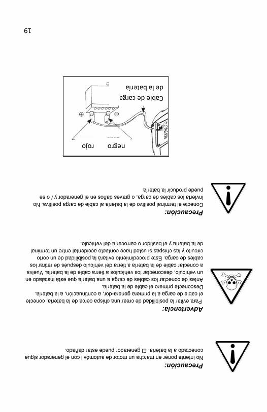
Precaución:
No intente poner en marcha un motor de automóvil con el generador sigue conectado a la batería. El generador puede estar dañado.
Advertencia: Para evitar la posibilidad de crear una chispa cerca de la batería, conecte el cable de carga a la primera genera-dor, a continuación, a la batería. Desconecte primero el cable de la batería. Antes de conectar los cables de carga a una batería que está instalado en un vehículo, desconectar los vehículos a tierra cable de la batería. Vuelva a conectar cable de la batería a tierra del vehículo después de retirar los cables de carga. Este procedimiento evitará la posibilidad de un corto circuito y las chispas si usted hace contacto accidental entre un terminal de la batería y el bastidor o carrocería del vehículo.
Precaución: Conecte el terminal positivo de la batería al cable de carga positiva. No invierta los cables de carga, o graves daños en el generador y / o se puede producir la batería
Cable de carga de la batería
negro rojo

18
Indicadores De Salida Y De Sobrecarga El indicador LED de salida (verde) parpadeará durante condiciones normales de funcionamiento. Si se sobrecarga el generador, o si hay un cortocircuito en el aparato conectado, la salida indica el LED (verde) se apaga, el LED indicador de sobrecarga (rojo) se encenderá y corriente al aparato conectado se apagará. Pare el motor si el indicador LED de sobrecarga (rojo) se enciende e investigar la fuente de sobrecarga
Nota: Sobrecarga sustancial que se ilumina continuamente el LED indicador de sobrecarga (rojo) puede dañar el generador. Sobrecarga marginal que se ilumina temporalmente el indicador LED de sobrecarga (rojo) puede acortar la vida útil del generador.
Antes de conectar un aparato al generador, compruebe que esté en buen estado, y que su clasificación eléctrica no supere la del generador. A continuación, arranque el motor y conecte el cable de alimentación del aparato Cuando se arranca un motor eléctrico, tanto el indicador LED de sobrecarga (rojo) y el indicador LED de salida (verde) se enciende al mismo tiempo. Esto es normal si el indicador LED de sobrecarga (rojo) se apaga después de aproximadamente cuatro (4) segundos. Si el indicador LED de sobrecarga (rojo) permanece encendido, póngase en contacto con Smarter Tools.
Conexión De La Carga De La Batería Cable
1. Antes de conectar el cable de carga de la batería a una batería que se instala en un vehículo, desconecte el cable de tierra de la batería del vehículo a partir del negativo (-) de la batería.
2. Conecte los cables de carga a la salida de CC del generador y luego a los terminales de la batería.
3. Conecte el cable rojo del cable de carga de la batería al terminal positivo de la batería (+) y el cable negro a la terminal negativa (-) de la batería.
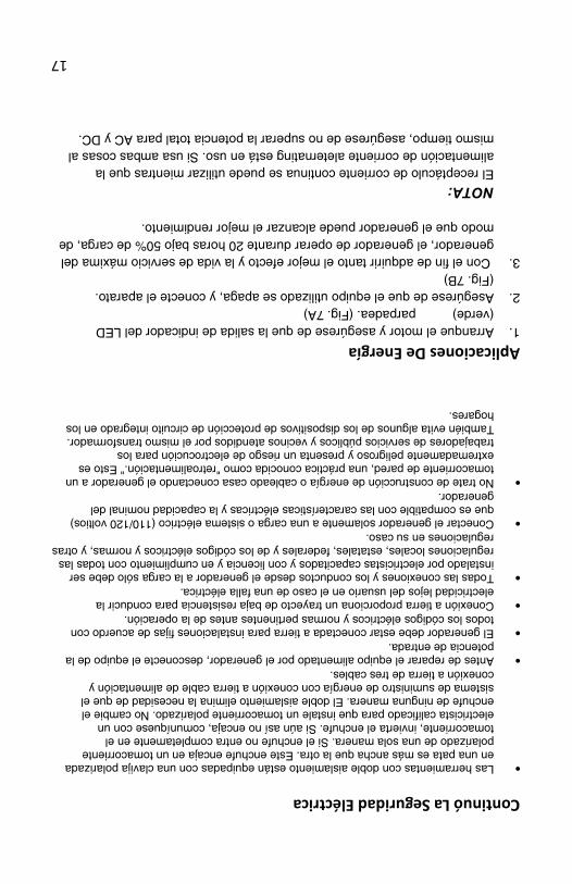
17
Continuó La Seguridad Eléctrica
• Las herramientas con doble aislamiento están equipadas con una clavija polarizada en una pata es más ancha que la otra. Este enchufe encaja en un tomacorriente polarizado de una sola manera. Si el enchufe no entra completamente en el tomacorriente, invierta el enchufe. Si aún así no encaja, comuníquese con un electricista calificado para que instale un tomacorriente polarizado. No cambie el enchufe de ninguna manera. El doble aislamiento elimina la necesidad de que el sistema de suministro de energía con conexión a tierra cable de alimentación y conexión a tierra de tres cables.
• Antes de reparar el equipo alimentado por el generador, desconecte el equipo de la potencia de entrada.
• El generador debe estar conectada a tierra para instalaciones fijas de acuerdo con todos los códigos eléctricos y normas pertinentes antes de la operación.
• Conexión a tierra proporciona un trayecto de baja resistencia para conducir la electricidad lejos del usuario en el caso de una falla eléctrica.
• Todas las conexiones y los conductos desde el generador a la carga sólo debe ser instalado por electricistas capacitados y con licencia y en cumplimiento con todas las regulaciones locales, estatales, federales y de los códigos eléctricos y normas, y otras regulaciones en su caso.
• Conectar el generador solamente a una carga o sistema eléctrico (110/120 voltios) que es compatible con las características eléctricas y la capacidad nominal del generador.
• No trate de construcción de energía o cableado casa conectando el generador a un tomacorriente de pared, una práctica conocida como "retroalimentación." Esto es extremadamente peligroso y presenta un riesgo de electrocución para los trabajadores de servicios públicos y vecinos atendidos por el mismo transformador. También evita algunos de los dispositivos de protección de circuito integrado en los hogares.
Aplicaciones De Energía 1. Arranque el motor y asegúrese de que la salida de indicador del LED
(verde) parpadea. (Fig. 7A) 2. Asegúrese de que el equipo utilizado se apaga, y conecte el aparato.
(Fig. 7B) 3. Con el fin de adquirir tanto el mejor efecto y la vida de servicio máxima del
generador, el generador de operar durante 20 horas bajo 50% de carga, de modo que el generador puede alcanzar el mejor rendimiento. NOTA: El receptáculo de corriente continua se puede utilizar mientras que la alimentación de corriente aleternating está en uso. Si usa ambas cosas al mismo tiempo, asegúrese de no superar la potencia total para AC y DC.
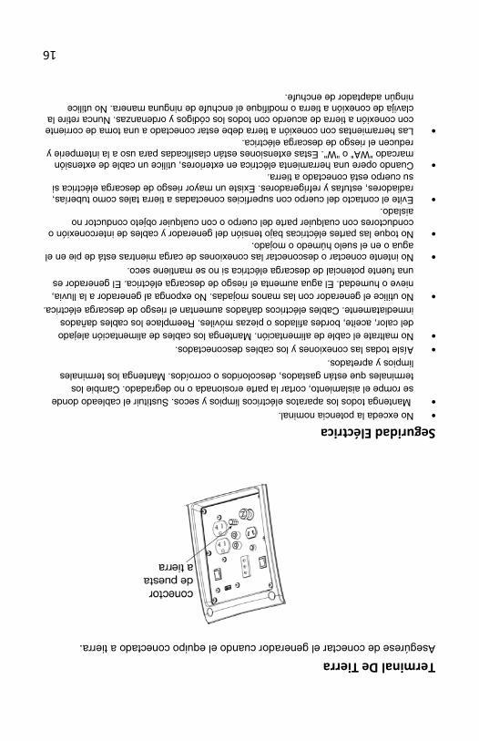
16
Terminal De Tierra Asegúrese de conectar el generador cuando el equipo conectado a tierra.
Seguridad Eléctrica • No exceda la potencia nominal. • Mantenga todos los aparatos eléctricos limpios y secos. Sustituir el cableado donde
se rompe el aislamiento, cortar la parte erosionada o no degradado. Cambie los terminales que están gastados, descoloridos o corroídos. Mantenga los terminales limpios y apretados.
• Aísle todas las conexiones y los cables desconectados. • No maltrate el cable de alimentación. Mantenga los cables de alimentación alejado
del calor, aceite, bordes afilados o piezas móviles. Reemplace los cables dañados inmediatamente. Cables eléctricos dañados aumentan el riesgo de descarga eléctrica.
• No utilice el generador con las manos mojadas. No exponga al generador a la lluvia, nieve o humedad. El agua aumenta el riesgo de descarga eléctrica. El generador es una fuente potencial de descarga eléctrica si no se mantiene seco.
• No intente conectar o desconectar las conexiones de carga mientras está de pie en el agua o en el suelo húmedo o mojado.
• No toque las partes eléctricas bajo tensión del generador y cables de interconexión o conductores con cualquier parte del cuerpo o con cualquier objeto conductor no aislado.
• Evite el contacto del cuerpo con superficies conectadas a tierra tales como tuberías, radiadores, estufas y refrigeradores. Existe un mayor riesgo de descarga eléctrica si su cuerpo está conectado a tierra.
• Cuando opere una herramienta eléctrica en exteriores, utilice un cable de extensión marcado "WA" o "W". Estas extensiones están clasificadas para uso a la intemperie y reducen el riesgo de descarga eléctrica.
• Las herramientas con conexión a tierra debe estar conectado a una toma de corriente con conexión a tierra de acuerdo con todos los códigos y ordenanzas. Nunca retire la clavija de conexión a tierra o modifique el enchufe de ninguna manera. No utilice ningún adaptador de enchufe.
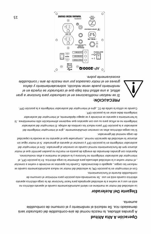
15
Operación A Alta Altitud A grandes altitudes, la mezcla normal de aire-combustible del carburador será demasiado rica. Se reducirá el rendimiento y el consumo de combustible aumenta.
Elegante Del Acelerador La velocidad del motor se mantiene en ralentí automáticamente cuando el aparato eléctrico no está en uso y se vuelve a la velocidad apropiada para hacer funcionar de la carga eléctrica aparato eléctrico cuando está en uso . Se recomienda esta posición para minimizar el consumo de combustible durante el funcionamiento. Con el interruptor en la posición ON, la velocidad del motor se reduce automáticamente cuando se reducen las cargas , apagado o desconectado. Cuando los aparatos se enciende o vuelve a conectar , el motor vuelve a la velocidad adecuada para alimentar la carga eléctrica. En la posición OFF, el interruptor del acelerador inteligente no funciona y la unidad se mantiene a altas revoluciones. Aparatos con grandes demandas de energía de puesta en marcha no pueden permitir que el motor alcance rpm de funcionamiento normal cuando se conectan al generador. Gire el interruptor del acelerador inteligente en la posición OFF y conectar el aparato al generador. Si el motor sigue sin alcanzar la velocidad de operación normal , compruebe que el aparato no se exceda la capacidad de carga nominal del generador. Si las cargas eléctricas altas se conectan simultáneamente , gire el interruptor inteligente del acelerador a la posición OFF para reducir los cambios de voltaje. El interruptor del acelerador inteligente no es eficaz para su uso con aparatos que requieren alimentación sólo momentánea . Si la herramienta o aparato se enciende y se apaga rápidamente, el interruptor del acelerador inteligente debe estar en la posición OFF. Cuando se utiliza la salida de CC , gire el interruptor del acelerador inteligente a la posición OFF.
PRECAUCIÓN: Si se realizan modificaciones en el carburador para funcionar a gran altitud, a una altitud más baja que el carburador se inyecta en el rendimiento puede verse reducido, sobrecalentamiento y daños graves en el motor causados por una mezcla de aire / combustible excesivamente pobre.
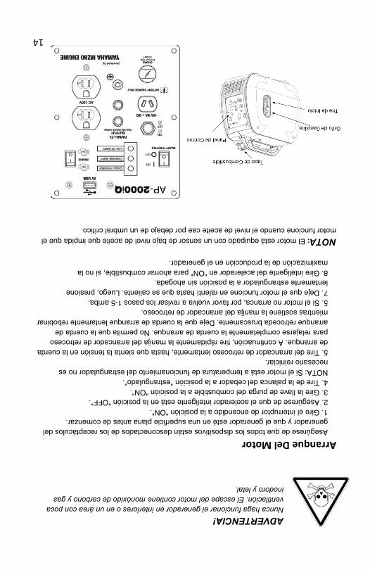
14
ADVERTENCIA! Nunca haga funcionar el generador en interiores o en un área con poca ventilación. El escape del motor contiene monóxido de carbono y gas inodoro y letal.
Arranque Del Motor
Asegúrese de que todos los dispositivos están desconectados de los receptáculos del generador y que el generador esté en una superficie plana antes de comenzar. 1. Gire el interruptor de encendido a la posición "ON". 2. Asegúrese de que el acelerador inteligente está en la posición "OFF". 3. Gire la llave de purga del combustible a la posición "ON". 4. Tire de la palanca del cebador a la posición "estrangulado". NOTA: Si el motor está a temperatura de funcionamiento del estrangulador no es necesario reiniciar. 5. Tire del arrancador de retroceso lentamente, hasta que sienta la tensión en la cuerda de arranque. A continuación, tire rápidamente la manija del arrancador de retroceso para relajarse completamente la cuerda de arranque. No permita que la cuerda de arranque retroceda bruscamente. Deje que la cuerda de arranque lentamente rebobinar mientras sostiene la manija del arrancador de retroceso. 5. Si el motor no arranca, por favor vuelva a revisar los pasos 1-5 arriba. 7. Deje que el motor funcione en ralentí hasta que se caliente. Luego, presione lentamente estrangulador a la posición sin ahogada. 8. Gire inteligente del acelerador en "ON" para ahorrar combustible, si no la maximización de la producción en el generador.
NOTA: El motor está equipado con un sensor de bajo nivel de aceite que impida que el motor funcione cuando el nivel de aceite cae por debajo de un umbral crítico.
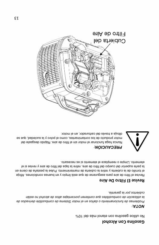
13
Gasolina Con Alcohol No utilice gasolina con etanol más del 10%
NOTA: Problemas de funcionamiento o daños en el motor Sistema de combustible derivados de la utilización de combustibles que contienen porcentajes altos de alcohol no están cubiertos por la garantía.
Revise El Filtro De Aire Revise el filtro de aire para asegurarse de que está limpio y en buenas condiciones. Afloje el tornillo de la cubierta y retire la cubierta de mantenimiento. Pulse la pestaña de cierre en la parte superior del cuerpo del filtro de aire, retire la tapa del filtro de aire y revise si el elemento. Limpie o reemplace el elemento si es necesario.
PRECAUCIÓN: Nunca haga funcionar el motor sin el filtro de aire. Rápido desgaste del motor producto de los contaminantes, como el polvo y la suciedad, que se dibuja a través del carburador, en el motor.
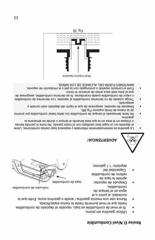
12
Revise El Nivel Combustible
• Utilizar gasolina sin plomo. • Si el nivel de combustible es bajo, repostar el depósito de combustible
hasta que el nivel aumenta hasta la marca especificada. • Nunca use una mezcla gasolina / aceite o gasolina sucia. Evite que la
suciedad, el polvo o el agua en el tanque de combustible.
• Después de repostar, apriete la tapa de relleno de combustible
• Capacidad del depósito: 1,1 galones
ADVERTENCIA!
• La gasolina es extremadamente inflamable y explosiva bajo ciertas condiciones. Llene
el depósito en un lugar bien ventilado con el motor parado. No fume ni permita llamas o chispas en el área en la que está llenando el tanque o donde se almacena la gasolina.
• No llene demasiado el tanque de combustible (no debe haber combustible por encima de la marca de límite superior Fig.3B).
• Después de repostar, asegúrese de que el tapón del depósito está cerrado y asegurado.
• Tenga cuidado de no derramar combustible al repostar. Los derrames de combustible o vapor de combustible puede incendiarse. Si se derrama combustible, asegúrese de que el área esté seca antes de arrancar el motor.
• Evite el contacto repetido o prolongado con la piel o la inhalación de vapores. MANTENER FUERA DEL ALCANCE DE LOS NIÑOS.
Nivel máximo Gasolina
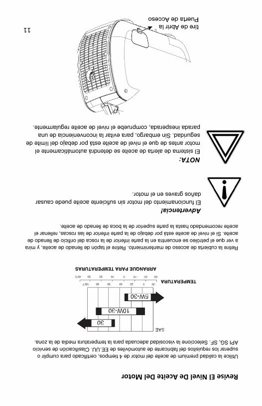
11
Revise El Nivel De Aceite Del Motor Utilice la calidad premium de aceite del motor de 4 tiempos, certificado para cumplir o superar los requisitos del fabricante de automóviles de EE.UU. Clasificación de servicio API SG, SF. Seleccione la viscosidad adecuada para la temperatura media de la zona.
TEMPERATURA ARRANQUE PARA TEMPERATURAS
Retire la cubierta de acceso de mantenimiento. Retire el tapón de llenado de aceite, y mira a ver que el petróleo se encuentra en la parte inferior de la rosca del orificio de llenado de aceite. Si el nivel de aceite está por debajo de la parte inferior de las roscas, rellenar el aceite recomendado hasta la parte superior de la boca de llenado de aceite.
Advertencia! El funcionamiento del motor sin suficiente aceite puede causar daños graves en el motor.
NOTA:El sistema de alerta de aceite se detendrá automáticamente el motor antes de que el nivel de aceite está por debajo del límite de seguridad. Sin embargo, para evitar la inconveniencia de una parada inesperada, compruebe el nivel de aceite regularmente.
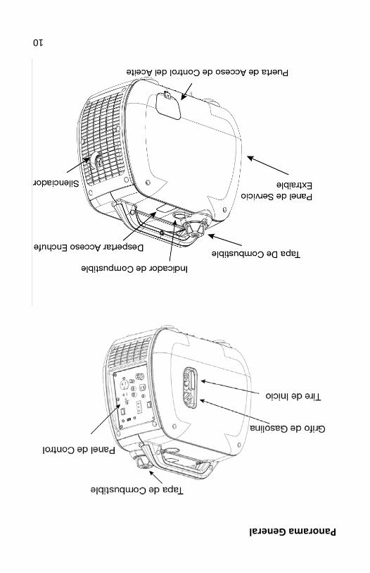
10
Panorama General
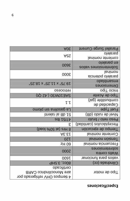
9
Especificaciones
Tipo de motor 4 tiempos OHV refrigerado por aire Monocilíndrico CARB certificado
Cilindrada (cc) 80cc, 3.5HP vatios para funcionar 1600 Watts contra sobretensiones 2000
Frecuencia nominal 60 Hz Tensión nominal 120 Corriente nominal 13.3A Tiempo de ejecución 8 Hrs (at 50% load) Receptáculos (cantidad) 3 Peso neto / bruto 47/51 lbs Nivel de ruido (dB) 51 dB al ralentí Fuel Type La gasolina sin plomo Capacidad de combustible (gal) 1.1
Tipo de Aceite SAE10W30 (.42 Qt) Inicio Tipo retroceso Dimensiones ensamblado 19.75” x 11.25” x 18.25”
paralelo potencia nominal 3000
Sobretensiones vatios en paralelo 3600
corriente nominal paralelo 25A
Parallel Surge Current 30A
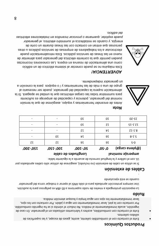
8
Productos Químicos
• Evite el contacto con el combustible caliente, aceite, gases de escape, y las superficies de sólidos calientes.
• Evite el contacto con combustibles, aceites y lubricantes utilizados en el generador. En caso de ingestión, acuda inmediatamente al médico. No inducir el vómito si se ha ingerido combustible. Por contacto con la piel, lavar inmediatamente con agua y jabón. Por contacto con los ojos, lavar inmediatamente los ojos con agua limpia y busque atención médica.
Ruido La exposición prolongada a niveles de ruido superiores a 85 dBA es peligroso para la audición. Use siempre protección aprobada para el oído ANSI al operar o trabajar cerca del generador cuando se está ejecutando .
Cables de extensión Si se utiliza un cable de extensión (no incluido), asegúrese de utilizar sólo cables aprobados por UL con el calibre y la longitud correcta de acuerdo a la siguiente tabla:
amperaje nominal Longitudes de cable (@plena carga) 0’-50’ 50’-100’ 100’-150’ 150’-200’
0-5 16 16 12 12
5.1-8 16 14 10 -
8.1-12 14 12 - -
12.1-15 12 10 - -
15-20 10 10 - -
Nota: Antes de encender herramientas y equipo, asegúrese de que la tensión nominal del generador, potencia y capacidad de amperaje es suficiente para suministrar todas las cargas eléctricas que la unidad se apagará. Si la alimentación supera la capacidad del generador, puede ser necesario al grupo de una o más de las herramientas y / o equipos para la conexión a un generador independiente. ADVERTENCIA! Esta máquina no se puede conectar al sistema eléctrico de un edificio como una alimentación de reserva en espera. Las conexiones incorrectas pueden permitir que la corriente eléctrica del generador para alimentar de nuevo en las líneas de servicios públicos. Esta retroalimentación puede electrocutar a los trabajadores de empresas de servicios públicos u otras personas que entran en contacto con las líneas durante un corte de energía, y cuando se restablezca el suministro eléctrico, el generador puede explotar, quemarse o provocar incendios en instalaciones eléctricas del edificio.
7
Precauciones Generales De Seguridad (Continuación) Gasolina y aceite (continuación)
• Combustible La gasolina y los vapores son inflamables y potencialmente explosivo. Utilice el almacenamiento de combustible adecuado y los procedimientos de manejo. Siempre tener varios extintores de incendios de clase ABC cercano.
• Mantenga el generador y los alrededores limpios en todo momento. Mantenga el generador por lo menos 5 metros de distancia de edificios y de otros equipos durante la operación.
• derrames de combustible o aceite deben limpiarse inmediatamente. Deshágase de los líquidos y materiales de limpieza como por los códigos y reglamentos locales, estatales o federales. Guarde trapos con aceite en un recipiente de metal cubierta.
• No guarde el combustible u otros materiales inflamables cerca del generador.
• No fume, mantenga las chispas, llamas u otras fuentes de ignición en todo el motor y el depósito de combustible. Los vapores del combustible son explosivos.
• Mantenga los objetos conductores de puesta a tierra, tales como herramientas, fuera de vista, las partes eléctricas y las conexiones para evitar chispas o arcos eléctricos. Estos eventos podrían encender los gases o vapores.
• No llene el tanque de combustible mientras el motor esté en marcha o mientras el motor está caliente. No utilice el generador con fugas conocidas en el sistema de combustible.
• La acumulación excesiva de los gases de combustible sin quemar en el sistema de escape puede crear una condición potencialmente explosivo. Esta acumulación puede producirse después de repetidos intentos fallidos de inicio, la prueba de la válvula, o parada del motor caliente. Si esto ocurre, se conecta abierto de drenaje del sistema de escape, si lo tiene, y permitir que los gases se disipen antes de intentar reiniciar el generador.
• Utilice único fabricante de motores de combustible y el aceite recomendado.
Los componentes calientes ADVERTENCIA! ESCAPE CALIENTE PUEDE QUEMAR. MOTOR CON PIEZAS DEL SISTEMA DE ESCAPE SE CALIENTAN MUCHO Y PERMANECEN CALIENTES DURANTE UN TIEMPO TRAS EL MOTOR ESTÁ OPERANDO. USE GUANTES AISLANTES O ESPERAR HASTA QUE EL MOTOR Y SISTEMA DE ESCAPE SE HAYAN ENFRIADO ANTES DE MANIPULAR LAS PARTES. Área de trabajo
• Mantenga su área de trabajo limpia y bien iluminada. Bancos de trabajo desordenados y las zonas oscuras pueden provocar accidentes.
• No opere herramientas eléctricas en atmósferas explosivas, como en presencia de líquidos inflamables, gases o polvo. Generadores generan chispas que pueden encender el polvo o los gases.
• Mantenga a los espectadores, niños y visitantes alejados mientras utiliza un generador. Proveer barreras o pantallas, según sea necesario.
6
Precauciones Generales De Seguridad
ADVERTENCIA! EL INCUMPLIMIENTO DE ESTAS INSTRUCCIONES PUEDE CAUSAR LESIONES GRAVES O LA MUERTE. PRECAUCIÓN: EL INCUMPLIMIENTO DE ESTAS INSTRUCCIONES PUEDE TAMBIÉN PROVOCAR DAÑOS AL EQUIPO Y / O EL ELEMENTO QUE ESTÁ TRABAJANDO EN O CON.
Monóxido de carbón
• El monóxido de carbono es un gas inodoro e incoloro. Respirar de escape que contiene este gas tóxico puede causar pérdida del conocimiento y puede llevar a la muerte.
• El escape del motor de este producto contiene sustancias químicas reconocidas por el estado de California como causante de cáncer, defectos de nacimiento u otros daños reproductivos.
• Cuando se ejecuta esta herramienta, asegúrese de que el área esté bien ventilada. Nunca haga funcionar el motor en un área cerrada. Hacer funcionar el motor en un área abierta o con un sistema de evacuación de gases de escape en un área cerrada.
• NUNCA use un generador dentro de las casas, garajes, sótanos u otras áreas parcialmente cerradas. Niveles mortales de monóxido de carbono pueden acumularse en estas áreas. El uso de un ventilador o abrir las ventanas y las puertas no proporciona suficiente aire fresco.
• Utilice únicamente un generador al aire libre y lejos de ventanas, puertas y conductos de ventilación. Estas aberturas pueden atraer el escape del generador.
• Incluso cuando se utiliza un generador correctamente, el CO puede filtrarse en el hogar. SIEMPRE utilice una alarma de CO de pilas o baterías de respaldo en el hogar.
• Si comienza a sentirse enfermo, mareado, o débil después de que el generador ha estado funcionando, mueva al aire fresco DE INMEDIATO. Consulte a un médico. Usted podría tener envenenamiento por monóxido de carbono.
ADVERTENCIA! EL ESCAPE CONTIENE VENENOSO MONÓXIDO GAS QUE PUEDE CAUSAR LA PÉRDIDA DE LA CONCIENCIA Y PUEDE CAUSAR LA MUERTE.
La gasolina y el aceite Este producto requiere de aceite y combustible. EL MOTOR NO ARRANCA SIN ACEITE. Trabaje en un área bien ventilada. Mantenga los cigarrillos, llamas o chispas lejos del área de trabajo o se almacena la gasolina.
ADVERTENCIA! LA GASOLINA ES EXTREMADAMENTE INFLAMABLE Y EXPLOSIVA BAJO CIERTAS CONDICIONES. MANTENER FUERA DEL ALCANCE DE LOS NIÑOS.
5
Este manual contiene información importante que usted necesita conocer y comprender a fin de garantizar su seguridad y correcto del equipo. Los símbolos ayudan a reconocer esta información. Lea el manual y preste atención a estas secciones.
Guarde estas instrucciones de seguridad importantes! Lea y comprenda todas las instrucciones de seguridad. Asegúrese de guardar para uso futuro.
ADVERTENCIA! ADVERTENCIAS INDICAN UNA CERTEZA O POSIBILIDAD FUERTE DE LESIONES O MUERTE SI NO SE SIGUEN LAS INSTRUCCIONES. PRECAUCIÓN: PRECAUCIONES PARA INDICAR LA POSIBILIDAD DE DAÑOS EN EL EQUIPO SI INSTRUCCIONES NO SE SIGUEN CORRECTAMENTE.
Nota: Notas proporcionan información útil.
ADVERTENCIA! FUNCIONAMIENTO INADECUADO O MANTENIMIENTO DE ESTE PRODUCTO PUEDE CAUSAR LESIONES GRAVES Y DAÑOS MATERIALES. LEER Y ENTENDER TODAS LAS ADVERTENCIAS E INSTRUCCIONES DE OPERACIÓN ANTES DE USAR ESTE EQUIPO. PRECAUCIONES BÁSICAS DE SEGURIDAD SE DEBEN CUMPLIR PARA REDUCIR EL RIESGO DE LESIONES PERSONALES.
Guarde estas instrucciones de seguridad importantes! Lea y comprenda todas las instrucciones de seguridad. Asegúrese de guardar para uso
futuro.

4
Tabla de contenidos
Introducción ............................................................................................. 05 Precauciones generales ........................................................................... 06 El monóxido de carbono . ......................................................................... 06 La gasolina y el aceite .............................................................................. 06 Los componentes calientes ...................................................................... 07 Área de trabajo ........................................................................................ 07 Químicos ................................................................................................. 08 Ruido ....................................................................................................... 08 Cables de extensión ................................................................................ 08 Especificaciones ..................................................................................... 09 Generador Información Funcionamiento ................................................. 10 Aceite del motor ...................................................................................... 11 Combustible ............................................................................................ 12 La gasolina que contiene alcohol ............................................................ 13 Arranque del motor .................................................................................. 14 Altitud ...................................................................................................... 15 Elegante Del Acelerador .......................................................................... 15 Terminal de tierra .................................................................................... 16 Seguridad eléctrica .................................................................................. 16 Aplicaciones de CA ................................................................................. 18 Conexión del cable de carga de la batería .............................................. 19 DC Interruptor .......................................................................................... 20 Desconectar el cable de carga de la batería ........................................... 20 Sistema de alerta de aceite ..................................................................... 20 Parada del motor ..................................................................................... 21 Parada del generador .............................................................................. 21 Transporte ............................................................................................... 21 Función Paralelo ..................................................................................... 22 Conexión del cable paralelo .................................................................... 22 Desactivación del generador, mientras que en paralelo .................................... 23 Mantenimiento ......................................................................................... 23 Cambio de aceite .................................................................................... 24 Filtro De Aire ............................................................................................ 24 Bujía ........................................................................................................ 25 Almacenamiento del generador .............................................................. 26 Solución de problemas ............................................................................ 27 Garantía Limitada ................................................................................... 29
lado Inglés Esquema de conexión ............................................................................. 29 Regiones diagrama .................................................................................. 30 Listado de piezas .................................................................................... 32
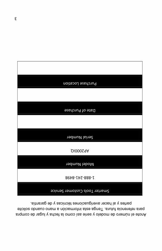
3
Anote el número de modelo y serie así como la fecha y lugar de compra para referencia futura. Tenga esta información a mano cuando solicite
partes y al hacer averiguaciones técnicas y de garantía.
Smarter Tools Customer Service
1-888-241-8498
Model Number
AP2000iQ
Serial Number
Date of Purchase
Purchase Location

2
Notas
________________________________________________________________________________________________________________________________________________________________________________________________________________________________________________________________________________________________________________________________________________________________________________________________________________________________________________________________________________________________________________________________________________________________________________________________________________________________________________________________________________________________________________________________________________________________________________________________________________________
AP-2000iQ Digital generador del inversor
Manual de instrucciones
ADVERTENCIA! Para reducir el riesgo de lesiones, el usuario debe leer y comprender el manual del propietario antes de usar.
NOTA: Conserve el recibo original de compra para demostrar la compra!
ADVERTENCIA!Para reducir el riesgo de