aowa:basic installer course1. 420-3-1-.04(y) conventional oss (onsite sewage disposal system)` a...
TRANSCRIPT

AOWA:Basic Installer Course 1

420-3-1-.04(y) Conventional OSS (Onsite Sewage Disposal System)`
a system for treating sewage that involves the use of a septic tank followed by a non-pressurized dispersion of effluent in an EDF such that the trench bottom and sidewalls are located completely in an unaltered natural soil and at a depth not greater than 60 inches below the unaltered natural ground surface. A shallow placement system is a conventional OSS that requires some amount of fill material above the EDF in order to provide a minimum soil cover of 12 inches
AOWA:Basic Installer Course 2

AOWA:Basic Installer Course 3
Topographic Profile
AOWA:Basic Installer Course 4
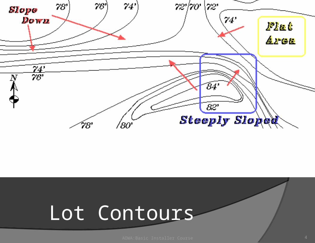
Lot Contours

AOWA:Basic Installer Course 5
Summer Water Table

AOWA:Basic Installer Course 6
Fall Water Table

AOWA:Basic Installer Course 7
Winter Water Table

AOWA:Basic Installer Course 8
Spring Water Table

AOWA:Basic Installer Course 9
Typical Lot

AOWA:Basic Installer Course 10
Setbacks (Page 36)
420-3-1-.45 Setback/Separation Distances
(1) The minimum setback/separation distances between EDFs, septic tanks, pump chambers, aerobic pre-treatment devices (including sand filters, biofilters, and ATUs), header lines, and similar devices, and various structures and topographic features, are contained in Table 5.
(2) No underground utility service or main , such as a water, electrical, phone, TV, or gas lines may cross over or under an EDF pipe.
(3) An OSS, the EDF, or the EDF replacement area shall not be located in an underground utility easement.
(4) Separation distances from a natural or man-made drainage system, embankment or cut may be reduced if sufficient information is submitted with the application to show that the drainage feature will not adversely affect the functioning of the EDF, and that effluent will not reach the feature, embankment or cut.
(5) See Rule 420-3-1-.89, Repair, Replacement and Inspection of an Existing OSS, for certain exceptions to separation distances for OSS repairs and replacements.
420-3-1-.46 Additional Setback/Separation for a Large System (See page 55)

AOWA:Basic Installer Course 11
Table 5
Minimum Setback/Separation distance for Components of Onsite System
Mimimum Horizontal Distance (ft)
To Tank, Treatment Device, Pump Other Components
Structure or Topographic Feature To EDF PumpChamber, Receptacles & D-Box of OSS
Another EDF 10 10 10
Basement 15 5 5
w/ drrain 25 5 5
Building foudation 5 5 5
Drainage way-Natural or Man-made 25 10 N/A
Embankment or Cut* 25 5 N/A
Hydric Soils & non-ponded wetlands 25 25 N/A
Interceptor drain and stormwater diversion
(feature located up-slope) 10 5 N/A
(feature located side-slope) 15 5 N/A
(feature located down-slope) 25 5 N/A
Potable (drinkable) water line** 5 5 5
Property line 5 5 N/A
Sinkholes and Caves*** 300 300 300

AOWA:Basic Installer Course 12
Table 5
Minimum Setback/Separation Distance for Components of Onsite Systems Mimimum Horizontal Distance (ft)
To Tank, Treatment Device, Pump Other Component
Structure or Topographic Feature To EDF Chamber, Receptacles & D-Box of OSS
Surface Water 50 25 10
Swimming Pool (in-ground) 10 5 N/A
Wells and Potable Springs 100 50 5
* Engineer may design system and reduce setback distance to a specified distance with acceptable justification, such as use of an ATU or use of solid or culvert pipe.
** May be less than 5 feet provided encapsulation of solid effluent line (pressurized or non-pressurized) for five feet from water line/well/spring.
***: Geologist may reduce setback distance with written documentation of geological investigation and specific setback distances set.
# The minimum setback distance for an EDF to wells or springs for subdivision lots recorded prior to October 18, 1978, shall be 50 feet with every effort made to exceed that distance.
This Table applies to small systems only see Table 6 and Table 7 for separations requirement for large systems

AOWA:Basic Installer Course 13
Vertical Setback420-3-1-.76 Soil Depth and Vertical Separation
(1) A minimum separation between the deepest trench bottoms and the average seasonal high extended saturation (ASHES) shall be required (See Table 15 for specific depth requirements).
(2) The depth to the ASHES is approximated by the highest occurrence of 2% or more contemporary redoximorphic features. (See Table 15 note 3). The minimum vertical separation (MVS) is based on chroma 2 or less (Munsell or equivalent) colors (more than 2% by volume). However, because saturation often occurs above these gray colors for shorter durations, the trench bottoms shall be at least the same elevation or higher than the top of this zone. (If there is sufficient evidence to suspect saturation occurs even higher than any obvious redox features for a significant period, groundwater monitoring may be required for a minimum of one normal wet season).
(3) When the soil evaluator encounters difficulty in determining the depth of the ASHES, he or she should consult with the LHD or a soil classifier.
(4) When actual monitoring is required to make a determination of the ASHES, a proposed plan shall be submitted to the LHD and the Board for review and approval.

Vertical Separation
14AOWA:Basic Installer Course
(5) The Board reserves the right to make the final decisions concerning ASHES and useable soil depth.
(6) Disposal trenches shall not be installed below the elevation of contemporary ASHES indicators without an approved drainage plan prepared jointly by an engineer and a soil classifier. The site is required to have a suitable outlet accessible by gravity.
(7) Other soil features that may occur in or below the soil and restrict the downward movement of water or hinder acceptable treatment and renovation of effluent shall be considered a restrictive layer. These features may include, but are not limited to, the following:
(a) Bedrock, hard and soft. (When restrictive rock layers are discontinuous or tilted such that the critical depths are highly variable, use the 50% rule. Any horizon with greater than 50% bedrock is unsuitable.)
(b) Some parent material layers with poor or massive structure and without adequate conducting pores (slowly or very slowly permeable).
(c) Fragipans, plinthic horizons that have 15% or more by volume plinthite, or similar features with inherent dense or brittle qualities.

AOWA:Basic Installer Course 15
LIMITATION SLIGHT MODERATE SEVERE EXTREME
SYSTEM Conv. Conventional Conv/Eng* (c/e) ENGINEERED
A/T Required
1.Percolation 1/ (Min/In)
5-30 31-60 61-90 91-120 *1-<5 121-240 >240 <1
2a. MVS 2/ from redox 3/ 6/
24” 18”
36” (c)*24” (e)
w/AT
18” 12”
24” w/AT2b. MVS from Hard Rock 6/
18” 18” 12”
2c. MVS from other RL 4/
12” 12” 6”
3.Min depth from NGS to ASHES or RL 5/
1. 24” trench depth +12”(24”) MVS = 36” (48”)2. 12” trench depth +12”(24”) MVS = 24” (36”)
(with 12” additional cover for # 2)
Same separation except for breaks allowed as specified in other parts of these rules
(Not necessarily from NGS)
4. Slope (%) 0-15 16-25 *26-40 (e) >40(OSS not allowed)
5.Flooding FrequencyChance/Year
NoneRare
< 5% Occasional
5-50 % Frequent
> 50% (OSS not allowed)
6. Landforms(Slope Positions)
SummitShoulderBack & Other Linear or Convex
Lower BackFoot
& Other Slightly Concave
Toe Head
Depressions & Other Concave
Swamp, Wetland, FloodplainHydric Soil Area
(OSS generally not allowed in these areas)
Table 15

AOWA:Basic Installer Course 16
Lot Line Set Backs5 ft.

AOWA:Basic Installer Course 17
Utility Line Set BackNot across or through

AOWA:Basic Installer Course 18
In-ground Pool Set Back –10 ft.Not under paved areas

AOWA:Basic Installer Course 19
Surface Water Set Back50 ft.

AOWA:Basic Installer Course 20
Well Set Back:100 ft. from EDF50 ft. from tank

AOWA:Basic Installer Course 21
Typical Lot

420-3-1-.42420-3-1-.42Gravel Field Standard Gravel Field Standard
Construction SpecificationsConstruction Specifications
AOWA:Basic Installer Course 22
(2)(a) Level Header (Appendix B-Figure 1)(2)(a) Level Header (Appendix B-Figure 1)
(2)(b) Serial Distribution (Appendix B-Figures 2 &3)(2)(b) Serial Distribution (Appendix B-Figures 2 &3)

AOWA:Basic Installer Course 23
Level Header System

AOWA:Basic Installer Course 24
Serial Distribution - On Contour

AOWA:Basic Installer Course 25
EDF Line With Contour

Parts of an Effluent Disposal Field
AOWA:Basic Installer Course 26
Crossover – Non-perforated pipe (rigid or flexible) which connects one effluent distribution
line to another in a serial distribution system
Effluent Disposal Field (EDF)– area into which sewage treated to at least primary standards is disposed into the
soil, typically via a network of rigid or flexible perforated EDF pipe
EDF Pipe– perforated pipe or its Board-approved equivalent palced in the EDF for the
purpose of distributing effluent Effluent Line
– a watertight pipe in an OSS which conveys wastewater from one component, such as a septic tank or treatment unit, to another such as an EDF d-box or header line
Header Line – rigid or flexible perforated pipe which receives effluent from an effluent line and
distributes the effluent to the EDF

AOWA:Basic Installer Course 27
Appendix B-Figure1

AOWA:Basic Installer Course 28
Level Header System

Level Header System.42 (2)(a)
AOWA:Basic Installer Course 29
Installed on relatively flat terrain
all trench bottoms installed on the same level
invert of header at least 4” below invert of septic tank
header is installed at the same elevation as the effluent distribution line
maximum length of an effluent distribution line is 100 feet.

Header Lines & Distribution Boxes
.42(2)(a)
AOWA:Basic Installer Course 30
Header lines are used in level header systems and are counted as part of the effluent disposal field UNLESS header line is non-perforated
Invert of header shall be at least 4” below the invert of the septic tank outlet
The header line shall be level.
Non-perforated header line shall not be counted as part of the required effluent disposal field

AOWA:Basic Installer Course 31
Level Header - Configurations

AOWA:Basic Installer Course 32
Level Header - Other

AOWA:Basic Installer Course 33
Level Header System

AOWA:Basic Installer Course 34
All Lines Level – Both Planes

AOWA:Basic Installer Course 35
Level Header Level Header DetailDetail
Invert of Header shall be Invert of Header shall be at leastat least
4” Below4” Below
invert of septic tank outletinvert of septic tank outlet

Serial Distribution System .42 (2)(b)
AOWA:Basic Installer Course 36
used when level header system cannot be usedused when level header system cannot be used
follows land contoursfollows land contours
trenches are level but at different elevationstrenches are level but at different elevations
effluent enters from watertight effluent line into a tee laid effluent enters from watertight effluent line into a tee laid levellevel
trenches connected by means of crossover linestrenches connected by means of crossover lines
trench maximum length 100' in each direction when trench maximum length 100' in each direction when measured from crossovermeasured from crossover

AOWA:Basic Installer Course 37
Serial DistributionSerial Distribution

AOWA:Basic Installer Course 38
Serial DistributionSerial Distribution

AOWA:Basic Installer Course 39
Calculating SlopeCalculating Slope% Slope = amount of % Slope = amount of riserise
over amount of over amount of runrun
6 feet runrun
2/6 = 1/3 = .33 x 100 = 33% slope
1
1
2
2 3 4 5 6
2
FT
RiseRise

AOWA:Basic Installer Course 40
Calculating Slope% Slope = amount of rise over amount of run
feet rise
feet run
1
1
2
2 3 4 5 6
2/6 = 1/3 = .33 x 100 = 33% slope
2/5 =.40 x 100 = 40% slope
7
2/7 = .28 x 100 = 28% slope
1/4 = .25 x 100 = 25%

AOWA:Basic Installer Course 41
Calculating Slope% Slope = amount of rise over amount of run
6 feet run
.5/5 = .10 x 100 = 10% slope
6”
1’ 2’ 3’ 4’ 5’ 6’

AOWA:Basic Installer Course 42
Calculating Slope% Slope = amount of rise over amount of run
.5/5 = .1 x 100 = 10% slope
6”
1’ 2’ 3’ 4’ 5’
6’
Restrictive layerRestrictive layer
Required 12-24” Separation From Limiting Zone
SpecificTrenchDepth

AOWA:Basic Installer Course 43
Serial Distribution SystemSerial Distribution System
Slope

AOWA:Basic Installer Course 44
Serial Trench Serial Trench DetailDetail

Crossovers .29(b)1 - 5Crossovers .29(b)1 - 5
AOWA:Basic Installer Course 45
invert of uppermost EDF pipe shall be at least 8” lower invert of uppermost EDF pipe shall be at least 8” lower than invert of septic tank outletthan invert of septic tank outlet
invert of a cross-over line at least 4" lower than invert of invert of a cross-over line at least 4" lower than invert of septic tank outletseptic tank outlet
crossover trench shall be no deeper than top of gravel in crossover trench shall be no deeper than top of gravel in preceding trench at the point it leaves the preceding preceding trench at the point it leaves the preceding trenchtrench
crossovers are laid on undisturbed earthcrossovers are laid on undisturbed earth
minimum of one crossover required for trenches < 100'minimum of one crossover required for trenches < 100'at least two crossovers required for trenches > 100'at least two crossovers required for trenches > 100'

AOWA:Basic Installer Course 46
Invert of Uppermost Line
MUST BE
AT LEAST 8” LOWER THAN THE
INVERT OF THE TANK OUTLET
8”Undisturbed
Earth

AOWA:Basic Installer Course 47
Level Header Detail
Invert of Header shall be at least
4” Below
invert of septic tank outlet

Header Lines & Distribution Boxes.42(3)(a-e)
AOWA:Basic Installer Course 48
(3) A distribution box may be used as follows:
(a) In lieu of a header line, to connect the effluent line to EDF pipes on the same elevation.
(b) To evenly distribute effluent to separate EDF field sections of an OSS.
(c) In lieu of serial distribution, to connect EDF pipes on different elevations.
(d) The distribution box shall be set on level grade. Non-perforated rigid pipe shall exit the distribution box for a minimum of 5 feet on level grade or equal grade before the EDF pipe (perforations) begins, as shown in Figure 5. Watertight effluent lines shall then convey effluent to the EDF pipe.
(e) Where EDF trenches are not placed in natural soil, such as in some controlled fill systems, a distribution box shall be used in lieu of cross-over lines and serial distribution.

AOWA:Basic Installer Course 49
Distribution Box

AOWA:Basic Installer Course 50
D-Box System

AOWA:Basic Installer Course 51
Serial D-Box System
Slope

Effluent Distribution Trenches 420-3-1-.42(3)
AOWA:Basic Installer Course 52
Width 18"-36" Depth
– Minimum 12" – Maximum 60"
Minimum soil backfill over line is 12" Minimum distance 5' from closest trench side wall of
adjacent trench Bottoms are LEVEL Maximum length 100' (except for serial distribution)

AOWA:Basic Installer Course 53
Trench Widths
18”
MIN.
24” 36”
MAX

AOWA:Basic Installer Course 54
Wider Trench Widths
? >36”Wider trenches may be approved by the local health department under special circumstances.

AOWA:Basic Installer Course 55
Trench DepthsConventional
12” Minimum
60” Maximum

AOWA:Basic Installer Course 56
Trench SpacingConventional
5 Feet Minimum

AOWA:Basic Installer Course 57
Slopes > 25% See: Appendix A, Table 4
Shall be designed by an engineer
Require:
1. Increased distances between trenches
2. Increased minimum depths

AOWA:Basic Installer Course 58
Trenches on 30% Slope

Effluent Distribution Lines 420-3-1-.29(4)
AOWA:Basic Installer Course 59
All pipe elevations in any 100-foot run of EDF pipe shall be within a 2-inch tolerance.
Minimum inside diameter 4" Pipe shall conform to applicable ASTM standards
– rigid or Simi-rigid and perforated– 2.2 sq in exfiltration area per ft - uniform on 1/2 circum. – perforations turned down (stripe is up)– pipes with slits are NOT approved (agriculture drain pipe)
Standard manufactured fittings compatible with the pipe shall be used to make all connections.

Effluent Distribution Line shall be installed in Board-approved aggregate
.42(6)
AOWA:Basic Installer Course 60
free of fines, dust, sand, or clay 1/4 to 2 1/2 inches in size gravel shall extend at least 8" below lowest point of line gravel shall extend to at least level with top of line Gravel shall be covered
– untreated building paper, heavy kraft paper, geotechnical fabric– impervious materials NOT APPROVED (plastic sheeting, polyethylene,
etc.

AOWA:Basic Installer Course 61
Conventional Trench Construction
12” Minimum
8” Min.
4” Pipe
12” Backfill
Barrier or Aggregate
Cover

Some Gravel-less seepage systems may be used
AOWA:Basic Installer Course 62
•Chambers
•Polystyrene Foam
•“Sock” Pipe

AOWA:Basic Installer Course 63
420-3-1-.43 EDF Dosing Requirements
(1) EDF's requiring more than 1,400 linear feet of EDF pipe, as determined by the Gravel Field Standard, shall be divided into separate and equal EDF's containing not more than 1,000 linear feet of EDF trench in each field and shall comply with the following:
(a) Each EDF shall be dosed not more than six times a day, unless the effluent is treated to secondary standards or better; then dosing requirements may be modified by an engineer, with Health Department approval. This dosing requirement does not apply to drip irrigation or controlled fill with LPP.
(b) Each dose shall not be greater than 70 percent of the volume of the perforated pipe or other disposal product in the section or sections of the EDF into which the pumping tank is to discharge, unless the effluent is treated to secondary standards or better then dosing requirements may be modified by an engineer, with Health Department approval.
(c) Dosing shall be accomplished through the use of effluent pumps from a properly sized and designed dosing tank (this does not apply to drip irrigation). The dosing tank shall meet the structural tank requirements in
Rule 420-3-1-.47, Septic Tank, Grease Trap and Holding Tank Standards and Specifications.
(d) Effluent pumps shall meet the requirements of Rule 420‑3‑1-.65, OSS Requiring Pumping of Effluent.
(e) The use of dosing siphons such as Miller siphons, may be considered by the Board.
(f) The use of low-pressure EDF pipe, placed within 4-inch diameter EDF pipe and placed in minimum 18-inch-wide trenches with a minimum of 8 inches of aggregate under the pipe, may be used as a means of equalizing the distribution of effluent over the EDF. The use of low-pressure EDF pipe shall require engineer design, using a recognized method.
***TYPICALLY WILL REQUIRE AN ENGINEER (and ADVANCED INSTALLER)

Shallow placement 420-3-1.68(1) (Appendix B-Figure 2)
AOWA:Basic Installer Course 64
420-3-1-.68 Shallow Systems
(1) The following are modifications to OSS or sites that may be used singly or in combination to overcome selected soil and site limitations. Except as required in this Rule, the provisions for design and installation of shallow OSS shall be the same as for other OSS.
(a) Sites classified Severe as to soil depth, soil wetness or other applicable limiting factor may be reclassified as Moderate with respect to that condition by utilizing shallow placement of effluent disposal trenches within the naturally occurring soil. Shallow trenches may be used where:
1. The trench depth, plus the required minimum separation distance below the trench bottom of the naturally-occurring soils that are present, is above the most limiting factor applicable to the site.
2. The trench design and construction is such that the trench bottom will meet the vertical and horizontal separation requirements in Rules 420-3-1-.45,Setback/Separation Distances, 420-3-1-.46, Additional Setback/Separation for a Large System, and 420-3-1-.76, Soil Depth and Vertical Separation.
3. The long-term acceptance rate is based on the hydraulically limiting naturally occurring soil horizon within 24 inches of the ground surface, or to a depth of 18 inches below the trench bottom, whichever is deeper.
4. The aggregate sidewalls or top of the EDF product are below original grade, and
5. Soil cover above the original grade is placed prior to installation at a uniform depth over the entire EDF, and extends laterally five feet beyond any outermost effluent disposal trench side or end wall before the 4:1 (25%) side slope begins. The soil cover shall be a minimum 12 inch depth over the aggregate or EDF product.

AOWA:Basic Installer Course 65
Shallow Placement
Conventional Zone
12” 4:1 Slope
Fill
Shallow Placement Zone
24”
12”
PE Design Required

AOWA:Basic Installer Course 66
Shallow Placement
12”
24”Conventional Zone
Shallow Placement Zone
4:1 Slope
12-24” Separation from
Restrictive layer

AOWA:Basic Installer Course 67
Shallow Placement System
Maintain MVS

AOWA:Basic Installer Course 68
If trench bottom is located at 18” below the surface of the ground, how much fill has to be added?
You know that the trench profile is 24”
8” of gravel + 4” pipe + 12” cover
Therefore:
24-18 = 6” fill or cover