“genteel” introduction to mri physics - ii: k-space ... · “genteel” introduction to mri...
TRANSCRIPT

“Genteel” Introduction to MRI Physics - II: k-space, timing, and
contrasts
Rudolph Pienaar, M.Eng, D.EngAssistant in Medical Imaging
Dept of Radiology Massachusetts General Hospital
Boston MA, USA
Magnetic Resonance Imaging:Deconstructing Timing Diagrams
Andrew J. M. Kiruluta, Ph.D.Dept of Radiology, MGH,
Dept of Physics, Harvard UniversityBoston MA, USA
“Throw physic to the dogs; I’ll none of it.”Shakespeare, Macbeth

Organization
• Quick recap• More on k-space• MR Sequence Timing diagrams• Imaging practicalities: echoes
– Spin – Gradient
• Image Contrasts– Relaxation effects– T1, T2, and proton density

05/19/09 Andrew J. M. Kiruluta 4
Magnetic Resonance• Protons and Neutrons have intrinsic angular momentum.• Atoms with an odd number of proton and/or odd number of
neutrons have a net magnetic moment=> MR active• For example, 1H exhibit nuclear magnetic resonance.
-
-
-
-
--
- -
--
-+
+
+
+ ++
+ +
+
Neutrons + protons
1H
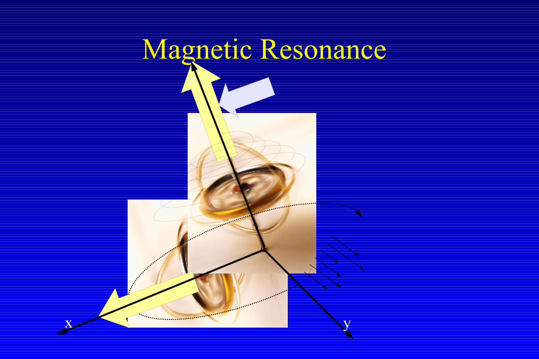
Magnetic Resonance
yx
z

Imaging
xy
z

Imaging
xy
z
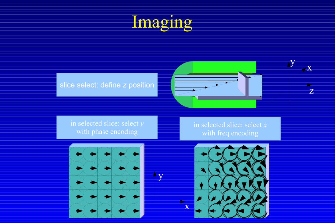
in selected slice: select ywith phase encoding
x
y
Imaging
xy
zslice select: define z position
in selected slice: select xwith freq encoding

xy
z
x
y
2D Imaging – x (freq) encoding

• Some of the following images are copyright: DM Higgins
• http://www.revisemri.com/tutorials/what_is_k_space/
k-space
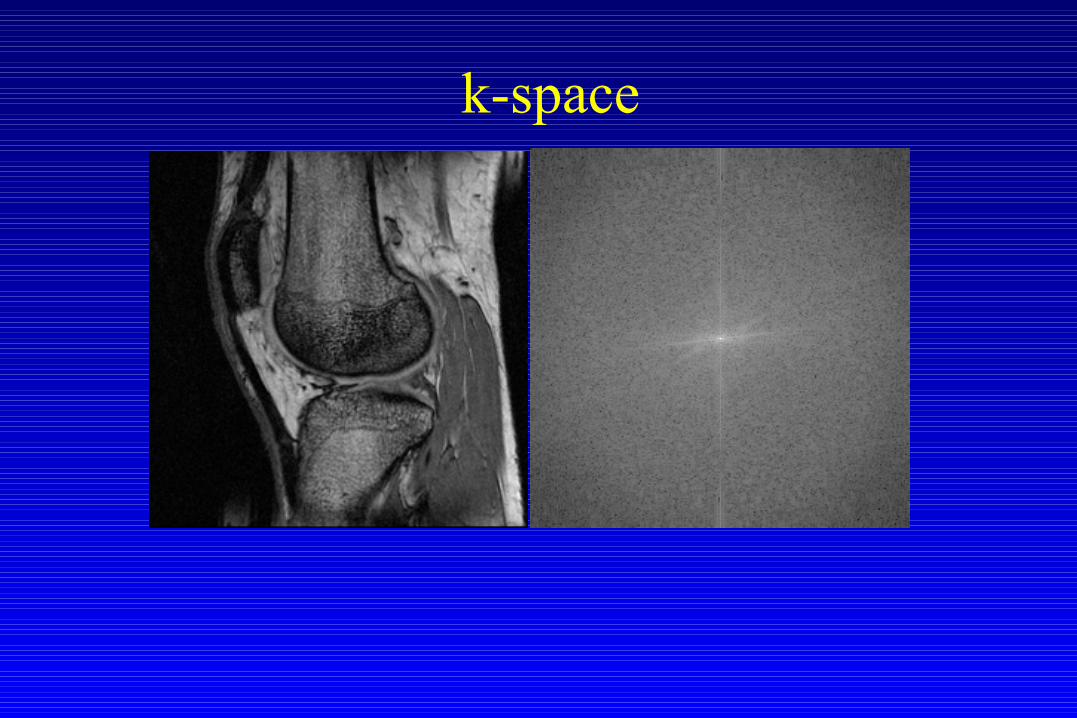
k-space
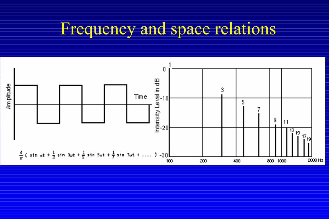
Frequency and space relations
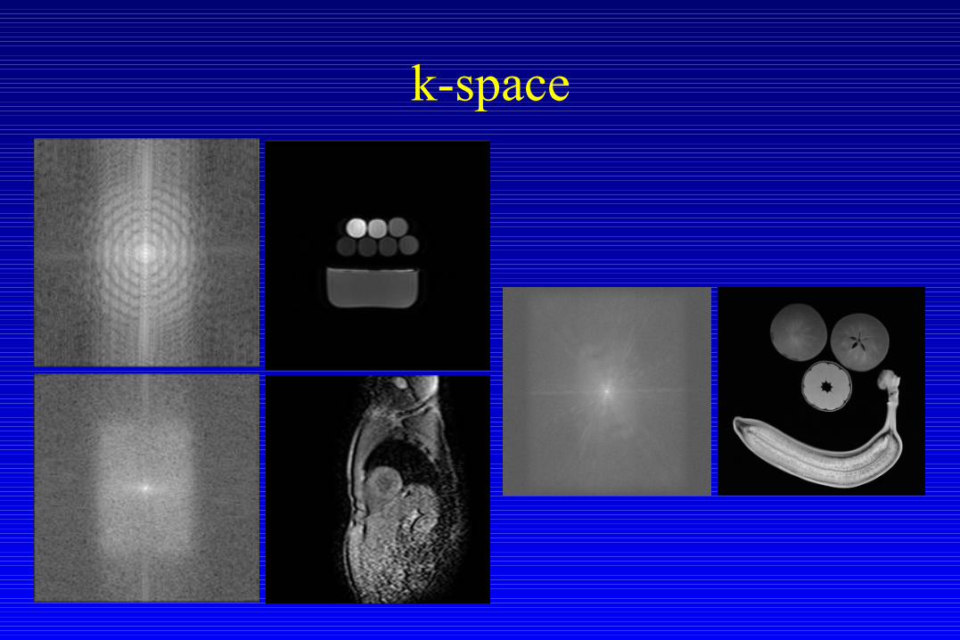
k-space

k-space

k-space

05/19/09 Andrew J. M. Kiruluta 16
kx
ky
kx
ky
kx
ky
k-space

Imaging
xy
zslice select: define z position
in selected slice: select xwith freq encoding
in selected slice: select ywith phase encoding
x
y

Gradients
f(x)G(x)
slope = m
mm
df/dt
05/19/09 Andrew J. M. Kiruluta 19
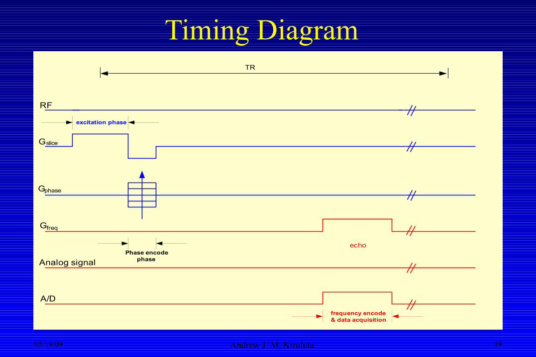
Timing Diagram
RF
G
G
G
A/D
slice
freq
phase
echo
TR
excitation phase
Phase encodephase
frequency encode& data acquisition
Analog signal

05/19/09 Andrew J. M. Kiruluta 20
Excitation Phase
RF
Gslice
TR
excitation phase
05/19/09 Andrew J. M. Kiruluta 21
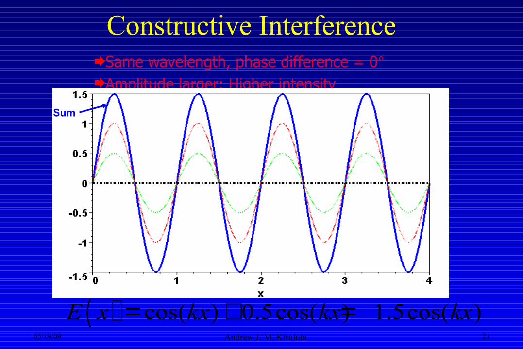
Constructive InterferenceSame wavelength, phase difference = 0°Amplitude larger: Higher intensity
Sum
( ) cos( ) 0.5cos( ) 1.5cos( )E x kx kx kx= + =
05/19/09 Andrew J. M. Kiruluta 22
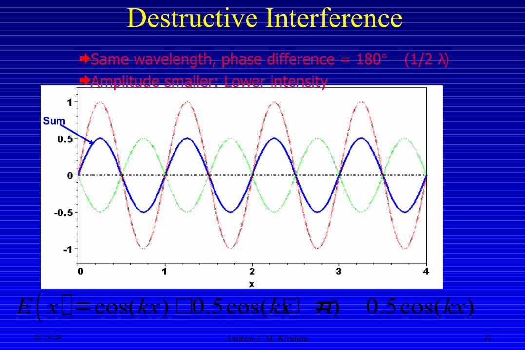
Destructive InterferenceSame wavelength, phase difference = 180° (1/2 λ)Amplitude smaller: Lower intensity
Sum
( ) cos( ) 0.5cos( ) 0.5cos( )E x kx kx kxπ= + + =

05/19/09 Andrew J. M. Kiruluta 23
Selective Excitation
Frequency
Mag
nitu
de
Time
RF
Am
plitu
de
(a)(b)
Pos
ition
(d)(c)
Slope = 1γ G
Frequency
)(
ˆ)(
0
0
zGB
zzGBB
z
z
+=⇒+=
γω
• Slice Encoding Gradient field
• Slice Location & Width:– Gradient strength – Center frequency – Bandwidth (BW) of RF
pulse

05/19/09 Andrew J. M. Kiruluta 24
Phase Encoding Step
RF
G
G
slice
phase
TR
phase encodingstep
kx
ky
phase encodingdirecion
0.5c
m1.
13cm
1.5c
m

05/19/09 Andrew J. M. Kiruluta 25
Frequency Encoding and Data AcquisitionGE
RF
G
G
G
A/D
slice
freq
phase
echo
TR
excitation phase
Phase encodephase
frequency encode& data acquisition
Analog signal
kx
ky
phase encodingdirecion
8.13cm

05/19/09 Andrew J. M. Kiruluta 26
Mechanisms of Spin Resynchronization
05/19/09 Andrew J. M. Kiruluta 27
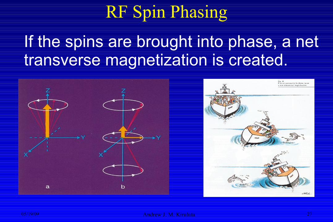
If the spins are brought into phase, a net transverse magnetization is created.
RF Spin Phasing

05/19/09 Andrew J. M. Kiruluta 28
Measuring the MR Signal
RF signals from precessing protons
RF antenna/Rx coil
B0
Starts off large when all phases are about equal
High frequency curve is at the average frequency
Decays away as different
components get different phases
05/19/09 Andrew J. M. Kiruluta 29
More about Echoes
“A fight against time…and signal decay”

The pros and cons of gradients
in selected slice: select xwith freq encoding
in selected slice: select ywith phase encoding
x
y
• Gradients, though useful in manipulating frequencies, also add dephasing, resulting in signal loss.
As we perform readout, wealso dephase (disturb the phaserelationship) along the readout

The pros and cons of gradients
• The most important k-space signal is at the center of k-space
• By adding additional gradients (and possibly another RF pulse), we can mitigate against gradient induced phase (and signal loss) and refocus our signal close to the center of k-space

05/19/09 Andrew J. M. Kiruluta 32
Spin Echo versus Gradient Echo
Gradient Echo
F I D gradient recalledecho
αR F p u l s e
rephase
dephase
signal
gradient
Spin Echo
FID spinecho
9 0 RF pulse
readoutfrequency encode
signal
gradient
18 00 RF pulse

05/19/09 Andrew J. M. Kiruluta 33
Spin & Gradient Echoes
Ref. Schering
• RF (spin) echo: flip the track (direction) so that they come back to the starting point.• Gradient echo: flip speeds (i.e. frequencies) so that the rabbit is slower than the turtle.
t < T2

05/19/09 Andrew J. M. Kiruluta 34
Spin Echo Timing Sequence
12
3 4
ky
kx
phase encoding direcion
K-space trajectory
RF
G
G
G
A/D
slice
freq
phase
echo
TR
excitation phase
Phase encodephase
frequency encode& data acquisition
Analog signal
TE/2 TE/2
1 2 3 4
Only 1 line of k-spaceis read per TR!
TR = 1s / 256 samples= 256s for whole slice= 4.2 minutes / slice

05/19/09 Andrew J. M. Kiruluta 35
A word about Contrast and Relaxation Effects
• ρ – Spin (Hydrogen/proton) density results in contrast between tissues
“water/fat content in tissue”
• T1 – due to energy exchange between spins and “lattice” ”time for sample to magnetize”
• T2 – dephasing time due to spin-spin energy exchange”time to loss of phase coherence”
• T2* - dephasing due to B0 inhomogenitiesgradients and inhomogeneous field increase
phase accumulation and reduce T2
10
05/19/09 Andrew J. M. Kiruluta 36
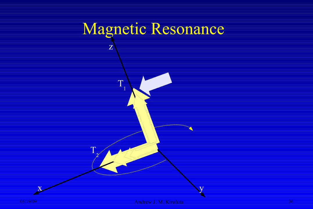
Magnetic Resonance
yx
z
T2
T1

05/19/09 Andrew J. M. Kiruluta 37
More about T1 and T2
19/05/09
38
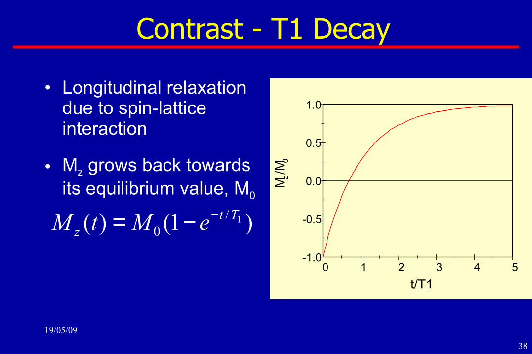
Contrast - T1 Decay
• Longitudinal relaxation due to spin-lattice interaction
• Mz grows back towards its equilibrium value, M0
)1()( 1/0
Ttz eMtM −−=
0 1 2 3 4 5-1.0
-0.5
0.0
0.5
1.0
t/T1M
z/M
0

19/05/09
39
Some sample tissue time constants - T1
Image, caption: Nishimura, Fig. 4.2
fat
liver
kidney
Approximate T1 values as a function of Bo
white matter
gray matter muscle

19/05/09
40
Contrast - T2 Decay• Transverse relaxation
due to spin dephasing
• T2 irreversible dephasing
• T2/ reversible dephasing
• Combined effect:
*2/
/22
*2
)0()(
111
TteMtM
TTT−
⊥⊥ =
+=0 1 2 3 4 5
0.0
0.2
0.4
0.6
0.8
1.0
t/T2*
Mx(
t)/M
x(0)

19/05/09
41
Some sample tissue time constants: T2
Table: Nishimura, Table 4.2
T2 of some normal tissue types
47muscle
92white matter
100gray matter
43liver
58kidney
85fat
T2 (ms)Tissue
19/05/09
42
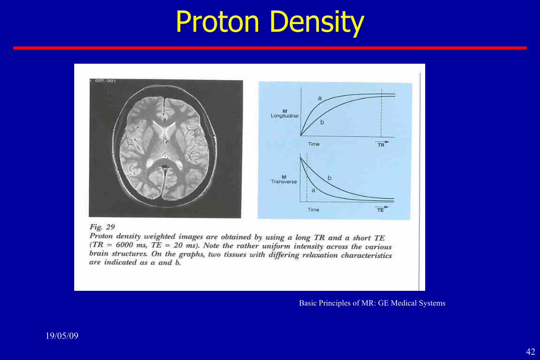
Proton Density
Basic Principles of MR: GE Medical Systems

19/05/09
43
T2 Contrast
CSF
White/Gray Matter
Sig
nal
Time
Long Echo-TimeShort Echo-Time

19/05/09
44
T1 Contrast
Sig
nal
Time
Sig
nal
Time
Short Repetition Long Repetition
CSF
White/Gray Matter
19/05/09
45
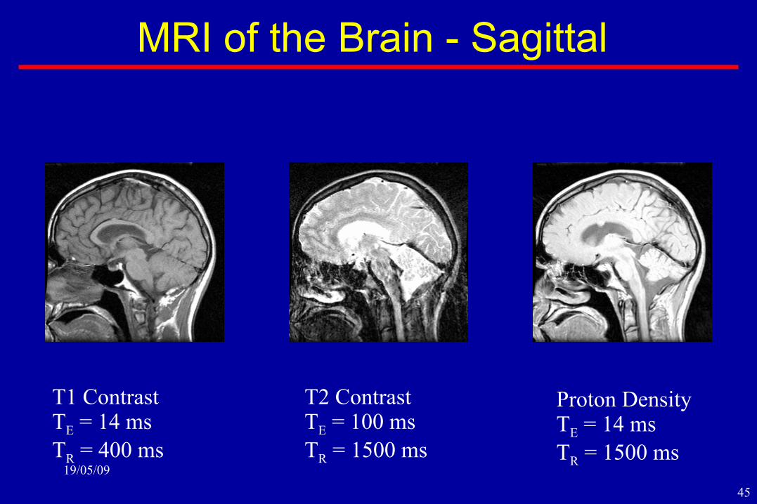
MRI of the Brain - Sagittal
T1 ContrastTE = 14 msTR = 400 ms
T2 ContrastTE = 100 msTR = 1500 ms
Proton DensityTE = 14 msTR = 1500 ms

19/05/09
46
What Physicians would do without images…
19/05/09
47
Useful links...
• MR Technology Information Portal Database:
• http://www.mr-tip.comhttp://www.mr-tip.com/serv1.php?type=db
• Basics of MRI (online book):
• http://www.cis.rit.edu/htbooks/mri/
• Revise MRI:
• http://www.revisemri.com/