anymedia access system: system release description … · lucent 363-211-200, issue 2 anymedia...
TRANSCRIPT
LUCENT 363-211-200, Issue 2AnyMedia Access System: System Release Description, R1.13.0.3October 2001
1 of 54
LUCENT TECHNOLOGIES — PROPRIETARYThis document contains proprietary information and is not
to be disclosed or used except in accordance with applicable agreements.
Contents
1. Overview 2<>
2. Features 4<>
3. CD ROM(s) Deliverables 9<>
4. System Compatibility 10<>
5. Operating Issues 14<>
6. Modem (CPE) Operating Issues 22<>
7. Turn-Up Procedures 24<>
8. Operational and Maintenance Procedures 39<>
9. Software Upgrade Procedures 45<>
10. Glossary 48<>
11. Appendix - QoS/Connection Admission Control 50<>
12. Appendix - GSI PPP Activation 52<>
AnyMedia® Access System:System Release Description forRelease 1.13.0.3 GA

2 of 54
LUCENT TECHNOLOGIES— PROPRIETARYThis document contains proprietary information and is not
to be disclosed or used except in accordance with applicable agreements.
LUCENT 363-211-200, Issue 2AnyMedia Access System: System Release Description, R1.13.0.3October 2001 1. Overview
1. Overview
The purpose of this software release description is to provide information about the AnyMediaAccess System Operations Software for Broadband Services (AOS-BB) and the related hardware.The CDROM with the AOS-BB software is labeled Release 1.13.0.3. The software version is identi-fied as R1.13.0.3-060nb when retrieved from the system.
The compatible AnyMedia Access System Graphical System Interface for the International Market (INTL) is the GSI Version 02.05.03-096 together with the narrowband Release 1.6 GA Update 3. For the North American Region (NAR) the compatible AnyMedia Access System Graphical System Inter-face is the GSI Version 02.02.01-162 together with the narrowband Releases R1.7.2.1 GA and R1.9.1 FSA.
The compatible AnyMedia Element Manager (AEM) Release is 1.13. For operation with the Element Manager please refer to the applicable documentation.
This document covers operations with the LPA901, LPA911, LPA941, LPA942 or LPA920 AFM in the NAR FAST shelf and the International AnyMedia Access System Mainshelf. The LPA900 and LPA910 AFM are not supported with this Release. For operations with the BAIU Shelf, refer to appli-cable documentation.
The examples and procedures in this document assume support via the GSI, not via the AnyMediaElement Manager (AEM). The GSI is designed for turn-up and local provisioning of a single AnyMe-dia shelf. In-service maintenance of AnyMedia systems should be done via the AEM.
For more detailed information on the AnyMedia Access System, see the AnyMedia Access SystemApplication, Planning and Ordering Guide; the AnyMedia Access System Installation Manual; and the AnyMedia Access System Commands and Procedures CD-ROM. These documents may be pur-chased by calling 888-LUCENT8.
This document contains the following parts:
• Features of the AOS-BB Software Release 1.13.0.3.• CD ROM(s) Deliverables - Deliverable files (Loadset) for AnyMedia Access System Release
1.13.0.3• System Compatibility - Identifies the compatible System Hardware, Firmware and Software for
Release 1.13.0.3.• Operating Issues - Operating Issues that have been identified in Release 1.13.0.3.• Modem (CPE) Operating Issues - Identifies operating Issues with customer premise equipment
(CPE) / Modem in Release 1.13.0.3.• Turn-Up Procedures - This section lists the recommended steps to turn-up the AnyMedia Access
System.

3 of 54
LUCENT 363-211-200, Issue 2AnyMedia Access System: System Release Description,R1.13.0.3
1. Overview October 2001
LUCENT TECHNOLOGIES — PROPRIETARYThis document contains proprietary information and is not
to be disclosed or used except in accordance with applicable agreements.
• Operational and Maintenance Procedures - This section provides procedures that will be useful during the operation and maintenance of Release 1.13.0.3.
• Software Upgrade Procedures - This section provides procedures to upgrade to Release1.13.0.3.
• Glossary• Appendix - QoS/Connection Admission Control• Appendix - GSI PPP Activation

4 of 54
LUCENT TECHNOLOGIES— PROPRIETARYThis document contains proprietary information and is not
to be disclosed or used except in accordance with applicable agreements.
LUCENT 363-211-200, Issue 2AnyMedia Access System: System Release Description, R1.13.0.3October 2001 2. Features
2. Features
The following AOS-BB features are supported in Release Release 1.13.0.3.
The feature set for the corresponding Narrowband Releases is described in detail in the System Release Descriptions.
• Release 1.6 GA Update 3 (International)SRD LUCENT 363-211-154
• Release 1.7.2.1 (North America Region)SRD LUCENT 363-211-177
• Release 1.9.1 (North America Region
The feature set for the corresponding AnyMedia Access System Element Manager will be described in detail in the System Release Descriptions.
2.1. Services
2.1.1. Broadband Services supported with Release 1.13.0.3
• ADSL over POTS via LPA400, LPA400B, LPA400C, LPA408, LPA416, LPA419• ADSL over ISDN via LPA414, LPA417• POTS and ADSL services provided by LPA404; combined POTS and ADSL card (NAR only)• POTS and ADSL services provided by LPA810; combined POTS and ADSL card (NAR only)• SDSL via LPS716 • ADSL modem supporting IP over ATM between modem and AP• ADSL modem supporting PPP for ATM• ADSL modem supporting 10BaseT Ethernet between modem and PC• SDSL modem supporting IP over ATM between modem and ADSL AP• SDSL modem supporting 10BaseT Ethernet between modem and PC• PCI slot resident internal ADSL modem• Internet Access via ADSL or SDSL• Remote LAN Access via ADSL or SDSL• AFM multiplexing of ADSL/SDSL access over DS3/E3 interface to ATM network• AFM multiplexing of ADSL/SDSL access over STM-1/OC-3c interface to ATM• Four-level QoS for applications using the LPA404, LPA408, LPA414, LPA416, LPA417, LPA419
and LPA810 ADSL application packs

5 of 54
LUCENT 363-211-200, Issue 2AnyMedia Access System: System Release Description,R1.13.0.3
2. Features October 2001
LUCENT TECHNOLOGIES — PROPRIETARYThis document contains proprietary information and is not
to be disclosed or used except in accordance with applicable agreements.
• Four-level (two simultaneous - CBR with nrtVBR or UBR / rtVBR with nrtVBR or UBR) QoS for applications using the LPS716 SDSL application pack
• 50:1 overbooking on nrtVBR• 10:1 overbooking on CBR and rtVBR• Network Timing Reference to the CPE when using the LPA416, LPA417, LPA419• Autosensing (ADSL FULL / LITE)• Dying Gasp event on xDSL link failure (Modem dependent)
2.2. System Capacity
2.2.1. Broadband System Capacity supported with Release 1.13.0.3
• Up to 15 ADSL AP packs per FAST or V5 shelf• Up to 15 combined POTS and ADSL AP packs per FAST shelf• Up to 15 SDSL AP packs per FAST or V5 shelf• Up to 16 ports per ADSL AP• Up to 8 combined POTS and ADSL ports per AP• Up to 16 ports per SDSL AP• Up to 7 ONUs per V5 shelf• Up to 240 simultaneous lines per FAST shelf• Up to 912 simultaneous lines per V5 shelf• DS3 capacity of 45 Mbps• E3 capacity of 34 Mbps• E1 IMA capacity of 8 E1 feeders (total 16 Mbps)• DSI IMA capacity of 8 DS1 feeders (total 18 Mbps)• Up to 4000 cross-connects (total of VC + VP-only cross-connects)• Up to 2000 cross-connects per shelf VP
2.3. Network Interfaces
2.3.1. Broadband Network Interfaces supported with Release 1.13.0.3
• Physical interface Access Network (AN) to Transport Network
— 2.048 Mbit/s electrical interface (E1) according to ITU G.703
— 34.368 Mbit/s electrical interface (E3) according to ITU G.703
— 44.736 Mbit/s electrical interface (DS3) according to Telcordia GR-499 (ITU G.703)

6 of 54
LUCENT TECHNOLOGIES— PROPRIETARYThis document contains proprietary information and is not
to be disclosed or used except in accordance with applicable agreements.
LUCENT 363-211-200, Issue 2AnyMedia Access System: System Release Description, R1.13.0.3October 2001 2. Features
— 155.52 Mbit/s optical interface (STM-1) according to ITU G.957 and G.707
— 155.52 Mbit/s optical interface (OC-3c) according to Telcordia GR-253
• Operational Interface
— DS3 ATM Data interface via LPA901 AFM
— E3 ATM Data interface via LPA911 AFM
— 10BaseT interface on AFM for local management operations
— VPI supported for In-Band Management Channel (ATM PVC)
— Up to 4 Shelf VPIs supported
— E1 IMA Data interface via LPA941 AFM
— DS1 IMA Data interface via LPA942 AFM
— Optical OC3/STM1 AFM feeder interface
— OC3/STM1 ATM Data interface via LPA920 AFM
2.4. Subscriber Interfaces
2.4.1. Asymmetric Digital Subscriber Line (ADSL)
• DMT• Rate adaptive and explicit rate ADSL-FULL and ADSL-LITE• Compatible with ANSI T1.413 issue 2, ADSL Metallic Interface and ITU G.992.1• ADSL-LITE compatible with ITU G.992.2 • ADSL over ISDN-BRA compatible with ETSI TS 101 388• On board splitter• 32 Kbit/s1 to 13.120 Mbit/s downstream• 32 Kbit/s to 1440 Kbit/s upstream
2.4.2. Symmetric Digital Subscriber Line (SDSL)
• ATM cell transport over 2B1Q-SDSL baseband coding with direct cell mapping• Flexible Symmetric Upstream/Downstream rates from 144 Kbit/s to 2.3 Mbit/s (8 steps)• Tip Ring pairs 1 - 16• Interoperability with Conexant chipset-based modems
1. Kbit/s = Kbps
7 of 54
LUCENT 363-211-200, Issue 2AnyMedia Access System: System Release Description,R1.13.0.3
2. Features October 2001
LUCENT TECHNOLOGIES — PROPRIETARYThis document contains proprietary information and is not
to be disclosed or used except in accordance with applicable agreements.
2.5. Operations Interfaces
• Integrated Graphical Systems Interface (GSI)
— Local operations via 10BaseT interface connection
— Local operation via PPP over Serial Console Port
— Windows 95/98 PC and Windows 2000 connection via PC LAN (requires crossover cable for direct connection).
— Windows NT connection via PC LAN (requires crossover cable for direct connection) with NAR GSI 2.2.1 only.
— Remote operation over ATM Operations Channel (ATM PVC)
• Alarm interface / LEDs
— CP Fault Faceplate LEDs on AFM and ADSL/SDSL APs
— Summary Alarm LEDs on AFM
— Summery LED on Fuse Control Module (FCM) (NAR only).
— CP Fault & Busy LEDs on combined POTS/ADSL AP (LPS404).
• Inventory and LED test interoperability with Graphical System Interface Software. This includes provisioned and unprovisioned AP packs.
• AnyMedia Element Manager (AEM) (Release 1.13 of AEM will support the R1.13.0.3)
2.6. OAM&P Capabilities
• AFM Simplex Operation• AFM Duplex Operation• Fault Management
— Loopbacks
— BER Monitoring
— LED Test
— Fault and status indication via LEDs and reports on the management interface
• Alarms
— Available via GSI
— Summary LEDs on AFM
— Shelf/slot/port information provided in trap messages
— Provisionable Alarm Severity
• Configuration Management
— Flexible rate adaptation, choice of min/max. range of ADSL rates
— Explicit rate adaptation, choice of four possible ADSL rates

8 of 54
LUCENT TECHNOLOGIES— PROPRIETARYThis document contains proprietary information and is not
to be disclosed or used except in accordance with applicable agreements.
LUCENT 363-211-200, Issue 2AnyMedia Access System: System Release Description, R1.13.0.3October 2001 2. Features
— Flexible rate adaptation for SDSL, (steps of eight symmetric rates for Upstream/Downstream transmission).
— Provisioning database backups and restores via GSI
— Software download/activation to AFM via GSI
— Provisioning via GSI
— Circuit pack inventory reporting
— Provisionable user password for GSI
• Maintenance
— Boot time self diagnostics for ADSL AP, SDSL AP, and AFM
— Performance monitoring for Feeders
— Performance monitoring for ADSL and SDSL AP transmission
— LED Test via GSI or at CTU or CIU pack in shelf
— On-demand ADSL or SDSL port test via GSI
— On-demand Corrupt CRC test via GSI (ADSL-FULL only)
— ATM Traffic Statistics by connection (max. 128 lines reporting Traffic Data)
— Support of in-service software upgrade for future releases
— Support of in-service AFM reboot
• Provisioning
— ATM Traffic Profiles supporting 4 levels of QoS
— Mismatch of Equipment (MEA) state if equipment doesn’t support requested service
— Connection Admission Control (CAC) verifies system can provide requested service
— User-set field for identifying ADSL/SDSL transmission profiles
— User-set field for cross-connect description
— Up to 4 Shelf VPIs allowed
— AP Port deletion
— Choice of Physical Port Mode (Default) or Logical Port Mode for provisioning and maintenance of xDSL interfaces.
— RS-232/PPP Console Port for local operations access
— Provisionable line (loop) timing mode for Feeder on LPA901, LPA911
— Alarm Severity
— Provisioning for QoS
— ATM Traffic Statistics by connection (max. 128 lines reporting Traffic Data)
— Up to 4 Shelf VPIs
— AP Port deletion
— Choice of Physical Port Mode or Logical Port Mode.

9 of 54
LUCENT 363-211-200, Issue 2AnyMedia Access System: System Release Description,R1.13.0.3
3. CD ROM(s) Deliverables October 2001
LUCENT TECHNOLOGIES — PROPRIETARYThis document contains proprietary information and is not
to be disclosed or used except in accordance with applicable agreements.
3. CD ROM(s) Deliverables
The AnyMedia Access System Operations Software for Broadband (AOS-BB) for Release 1.13.0.3 is delivered by Lucent on CD-ROM. The software version number is identified as R1.13.0.3-060nbwhen retrieved from the system.
AnyMedia Access System Graphical System Interface Software (GSI) Versions are delivered by Lucent on CD-ROM or SW download. The appropriate GSI Software Version shall be chosen accord-ing to chapter Section 4.3 on page 12. This SW Version is supposed to control Broadband and Nar-rowband operation.
Software deliverables for the corresponding Narrowband Service Releases are described in Section4.3 on page 12.

10 of 54
LUCENT TECHNOLOGIES— PROPRIETARYThis document contains proprietary information and is not
to be disclosed or used except in accordance with applicable agreements.
LUCENT 363-211-200, Issue 2AnyMedia Access System: System Release Description, R1.13.0.3October 2001 4. System Compatibility
4. System Compatibility
4.1. Release 1.13.0.3; Hardware and Firmware Compatibility
The following table lists the version of AnyMedia equipment that is compatible with Release 1.13.0.3.
Type Model Series/Version Description
AFMDS3 LPA901 1:41, 1:31, 1:2 DS3 Asynchronous Transfer Mode Feeder Multiplexer
AFME3 LPA911 1:31, 1:2 E3 Asynchronous Transfer Mode Feeder Multiplexer
AFMO LPA920 1:21, 1:1 Optical STM-1/OC-3c Asynchronous Transfer Mode Feeder Multiplexer
E1 IMA AFM LPA941 1:2 E1 Inverse Multiplexing over ATM AFM
DS1 IMA AFM LPA942 1:? DS1 Inverse Multiplexing over ATM AFM
ADSL4 AP LPA400 2:2, 2:3, 2:42 Asymmetric Digital Subscriber Line Application Pack
ADSL4 AP LPA400B 1:1 Asymmetric Digital Subscriber Line Application Pack
ADSL4 AP LPA400C 1:1-1:3 Asymmetric Digital Subscriber Line Application Pack
POTS/ADSL AP LPA404B 1:1 Asymmetric DIgital Subscriber Line / POTS Application Pack (4-line)
ADSL8p AP LPA408 2:2-2:6 Asymmetric Digital Subscriber Line Application Pack(8-line)
ADSL4i AP LPA414 3:4, 3:3 Asymmetric Digital Subscriber Line over ISDN Application Pack (4-line)
ADSL16p AP LPA416 4:4 Asymmetric Digital Subscriber Line Application Pack (16-line) Supports Network Timing Reference to the CPE
ADSL16i AP LPA417 1:1 Asymmetric Digital Subscriber Line over ISDN Application Pack (16-line) Supports Network Timing Reference to the CPE

11 of 54
LUCENT 363-211-200, Issue 2AnyMedia Access System: System Release Description,R1.13.0.3
4. System Compatibility October 2001
LUCENT TECHNOLOGIES — PROPRIETARYThis document contains proprietary information and is not
to be disclosed or used except in accordance with applicable agreements.
4.2. Release 1.13.0.3; Software Compatibility
The following table identifies the software versions which are compatible with Release 1.13.0.3. This table lists appropriate software elements (e.g. AFM, GSI, etc.) and associated version code(s).
ADSL16p AP LPA4193 S1:1 Asymmetric Digital Subscriber Line Application Pack (16-line) Supports Network Timing Reference to the CPE
POTS/ADSL AP LPA810 S1:1 Asymmetric DIgital Subscriber Line / POTS Application Pack (8-line ADSL / 32-line POTS)
SDSL16 LPS716 S1:1 Symmetric Digital Subscriber Line Application Pack(16-line)
1. Improved processing performance2. LPA400 does not support Alcatel inter-operability and ADSL-LITE compatibility with G.992.23. LPA419 has same functionality as LPA416 but low impedance path in local loop test circuit
AnyMedia Shelf Software Element SW Version Code
FAST (NAR)V5 (INTL)
AOS-BB R1.13.0.3-060nb
FAST (NAR) AOS-GSI AOS-GSI 02.02.01-162(Build - 162)
V5 (International) AOS-GSI AOS-GSI 02.05.03-096(Build - 096
Type Model Series/Version Description

12 of 54
LUCENT TECHNOLOGIES— PROPRIETARYThis document contains proprietary information and is not
to be disclosed or used except in accordance with applicable agreements.
LUCENT 363-211-200, Issue 2AnyMedia Access System: System Release Description, R1.13.0.3October 2001 4. System Compatibility
4.3. Release 1.13.0.3; Corresponding Narrowband Release Software
The following table lists the versions of COMDAC and GSI compatible with AnyMedia Access Sys-tem Release 1.13.0.3
4.4. Release 1.13.0.3; Corresponding Element Manager
Release Software
The following table lists the versions of the Element Manger compatible with AnyMedia Access Sys-tem Release 1.13.0.3 and corresponding narrowband releases.
4.5. Customer Premise Equipment (CPE) compatibility; Broadband
Refer to your Local Customer team or to LUCENT Customer Technical Support for the latest informa-tion on ATM xDSL CPE modems that are currently supported.
AnyMedia ShelfCOMDAC SW
ReleaseGSI
V5 (INTL) Release 1.6 GA Update 3AOS-NB 01.06.20
AOS-GSI 02.05.03-096
FAST (NAR) ReleasesR1.7.2.1 GA and R1.9.1 FSA
AOS-GSI 02.02.01-162
AnyMedia Shelf Narrowband Release AEM
V5 (INTL) Release 1.6 GA Update 3 Release1.13
FAST (NAR) Release 1.7.2.1 Release 1.13

13 of 54
LUCENT 363-211-200, Issue 2AnyMedia Access System: System Release Description,R1.13.0.3
4. System Compatibility October 2001
LUCENT TECHNOLOGIES — PROPRIETARYThis document contains proprietary information and is not
to be disclosed or used except in accordance with applicable agreements.
4.6. Customer Documentation
The following table identifies the Customer Documentation version applicable to Release 1.13.0.3. The table lists the appropriate customer documentation identification and associated issue code(s).
4.6.1. International Releases
The customer Documentation for Release 1.6 (NB) and R1.13 (BB) is also available on CD-ROM (LUCENT 363-211-114).
4.6.2. North American Region Releases
Document Identification Issue Code
Applications, Planning Guide (APOG) 363-211-110 8
Ordering Guide 363-211-144 1
Command and Procedures (C&P)
for ATM and xDSL
363-211-133 3
Installation Manual for AC-Racks 363-211-206 5
Installation Manual for DC-Racks and Single Shelf 363-211-207 5
Installation Manual for In-house ONU( ONU-IMI) 363-211-155 3
Installation Manual for Outdoor ONU (ONU- IMO) 363-211-116 2
Document Identification Issue Code
Applications, Planning Guide (APOG) 363-211-101 9
Ordering Guide 363-211-125 9
Command and Procedures (C&P)
for ATM and xDSL
363-211-100 9
Installation Manual 363-211-102 9
Engineering Guidelines 363-211-178 1

14 of 54
LUCENT TECHNOLOGIES— PROPRIETARYThis document contains proprietary information and is not
to be disclosed or used except in accordance with applicable agreements.
LUCENT 363-211-200, Issue 2AnyMedia Access System: System Release Description, R1.13.0.3October 2001 5. Operating Issues
5. Operating Issues
This section lists all operating issues associated with Release 1.13.0.3.
Operating issues of the corresponding Narrowband Releases and Element Manager Releases aredescribed in detail in the associated System Release Descriptions.
5.1. Release 1.13.0.3 Operating Issues
The following bullet list identifies operating issue(s) associated with Release 1.13.0.3. This list con-tains the operating issue(s) and its associated suggested workaround.
1. ISSUE: TURNUP
a. Soft reset of the AFM may result in interruption of data on some older-vintage LPA400 packs in Subshelf.
Work Around: Use Series 2:2 LPA400 APs in Subshelf.
b. System allows provisioning cross-connects on SDSL ports with Default ATM traffic profiles labelled ADSL.
Work Around: Select SDSL Default ATM traffic profiles for SDSL ports.
c. Changing the port numbering mode from physical to logical may cause all cross connects to be deleted or to be displayed incorrectly.
Work Around: Change port numbering mode from physical to logical prior to creating cross connects.
d. Software download to an AFM may fail.
Work Around. If software download fails, repeat the software download.
e. Download of software to APs occasionally may FAIL. Alarms may be reported for download failure, or download in-progress not completed (e.g., blinking LED on AP) after 15 minutes.
Work Around: Reset APs via GSI Pack Provisioning screen. If download failure is reported again, the APs failing download must be removed and then re-inserted one-by-one.
f. If an AP is removed and re-inserted during software download, the AP and ports may not recover until download is completed.
Work Around: Do not remove or insert packs during software download. R&R AP to recover.
g. Provisioning may become very slow after enabling Feeder Port-2 (Daisy-chain configuration).
Work Around: After provisioning Feeder Port-2, wait 15 minutes before additional provision-ing.

15 of 54
LUCENT 363-211-200, Issue 2AnyMedia Access System: System Release Description,R1.13.0.3
5. Operating Issues October 2001
LUCENT TECHNOLOGIES — PROPRIETARYThis document contains proprietary information and is not
to be disclosed or used except in accordance with applicable agreements.
h. Provisioning of a port or a cross connect via the GSI may fail due to empty fields even if all the fields in the screen have been filled in.
Work Around: Click OK on the message and re-input information.
i. The system does not distinguish between profiles of the same type (xDSL, ATM or PM) with the same name. The GSI chooses the first profile with that name when making a connection.
Work Around: Always create profiles with unique names.
j. The operational state of a cross connect may not be correct after a database restore or a reboot.
Work Around: Retrieve the Data Status of the port for all suspect cross connects to deter-mine the operational state of the cross connect.
K. Slot states for APs in the subshelf (ONU) may not be reported correctly, especially if the equi-page changed while the fiber between the OAP and the ONU was disconnected. The shelf view may also display removed Aps and may not display inserted APs.
Work Around: Rely on the Operational state to determine if a provisioned slot is equipped.
L. If an LPA400 or LPA400B is provisioned while it is inserted in a subshelf, the AP may never complete initialization.
Work Around: Always provision the AP slot prior to inserting the AP.
m. If an AP is inserted or provisioned while the AFM is undergoing software download, the AFM is undergoing the reset after the software download or the existing APs are being downloaded, the new AP may fail software download.
Work Around: Wait until the reboot after the software download has completed and all of the inserted and provisioned APs have completed their software download before inserting or pro-visioning any new APs.
n. Setting a shelf VP to the VP of a deleted VP-only cross connect may fail.
Work Around: Verify that the AFM in slot 16 is Active. Set the system to Simplex and then do a soft reboot of the AFM. After the AFM has completed its reboot, set the system back to Duplex. Add the shelf VP.
o. Setting an rt-VBR shelf VP to the VP of the OAMvp may fail.
Work Around: Set the rt-VBR shelf VP first and the set the OAMvp.
p. Setting the Timing of a feeder after the AFM clock has been set may fail.
Work Around: Verify that the AFM in slot 16 is Active. Set the system to Simplex and then do a soft reboot of the AFM. After the AFM has completed its reboot, set the system back to Duplex. Set the feeder timing reference. Now set the clock.
q. After completion of software Activation, the software loads listed in the Activation screen may not be correct.
Work Around: Close the Activation screen and then re-open it to determine if the activation has completed properly.

16 of 54
LUCENT TECHNOLOGIES— PROPRIETARYThis document contains proprietary information and is not
to be disclosed or used except in accordance with applicable agreements.
LUCENT 363-211-200, Issue 2AnyMedia Access System: System Release Description, R1.13.0.3October 2001 5. Operating Issues
2. ISSUE: GSI
a. AFM LEDs/alarms display at GSI may be incorrect after upgrade or AFM protection switch.
Work Around: Refresh Shelf View at GSI.
b. After AFM protection switch, GSI may disconnect, may not be able to reconnect to shelf.
Work Around: Provision the AFM pinging parameters as follows:
From Menu => View => Options, select SNMP. Change the “No. Retries” to 16. The GSI dis-connect time (seconds) is equal to the (No. Retries) x (Interval) + (Timeout).
c. No traps will be reported to a new GSI host if the Autonomous Message Destination (also known as NMS) table is full. No warning message is displayed when GSI connects.
Work Around: Delete at least 1 of the addresses in the NMS Address list at Communications screen of GSI, then disconnect and reconnect GSI.
d. In the inventory screen, the circuit pack type is not correct. A generic circuit pack type of ADSL F+L is reported for ADSL APs and a circuit pack type of SDSL is reported for SDSL APs.
Work Around: Log out of the AFM and log into the Comdac. Retrieve the inventory to obtain the correct circuit pack type.
e. Cannot install 02.05.03-096 GSI on Windows NT or Windows 2000 machines.
Work Around: Must use Windows 95/98 with this GSI.
f. When a customer adds the 02.02.01-162 GSI to a computer with the Windows NT or Windows 2000 operating system, the GSI may not install or work properly. Run-time error 713 and/or 429 may be returned from provisioning screens.
Work Around: After installing GSI on NT machine, MUST do both of the following actions:
From the Start menu select Run and type: regsvr32.exe msstdfmt.dll
From the Start menu select Run and type: regsvr32.exe scrrun.dll
g. PC running GSI returns Run-time error ‘91’ message or VBAJET32.dll Error message: “The Jet VBA file (VBAJET.dll for 16-bit versions or VBAJET32.dll for 32-bit versions) cannot be found or registry entry is missing try reinstalling the application that returned the error.”
Workaround: According to Microsoft, solution is to download and run the following files: dcom95.exe (Distributed Component Object Model for Windows 95)
or
dcom98.exe (Distributed Component Object Model for Windows 98)

17 of 54
LUCENT 363-211-200, Issue 2AnyMedia Access System: System Release Description,R1.13.0.3
5. Operating Issues October 2001
LUCENT TECHNOLOGIES — PROPRIETARYThis document contains proprietary information and is not
to be disclosed or used except in accordance with applicable agreements.
and
mdac_typ.exe (Microsoft Data Access Components)
Files available at http://www.microsoft.com/data/download.htm
Attention Windows 95 Users: DCOM for Windows 95 must be installed before installing MDAC 2.0x or 2.1x. DCOM for Windows 95 is available for download at
http://www.microsoft.com/com/dcom.asp
After completing the above steps please try to run the GSI again.
h. May not be able to connect to AFM via Console port.
Work Around: Check that maximum 15-foot (4.5 m) serial cable is connected. If repeated attempts to connect fail, try power cycle the PC used. If still no connection, the AFM should be reset.
3. ISSUE: ALARMS and CONDITIONS
a. Feeder RAI alarm may be reported on Feeder Port-1 on Active and Standby AFMs after AFM protection switch.
Work Around: Recover by break/restore Feeder in Receive direction.
b. Link Down Event message sent for broken xDSL link may report HBER instead of LOS for loops longer than 10 Kft of 26 AWG (3000m with 0.4 mm wire diameter).
Workaround: Ignore the reason code reported for Link Down.
c. Loss of Frame (LOF) alarm may be reported on LPA901, LPA911 if Feeder Port 2 (daisy-chain) is enabled with no signal or bad signal received.
Workaround: Assume Loss of Signal (LOS) present and check feeder cable or provisioning downstream.
d. Feeder alarm for LOF may not be reported for DS3/E3 or IMA Feeder after restoring Feeder from LOS condition. Data service will not be supported until the mis-framed feeder is fixed.
Work Around: If data service is not recovered after Feeder LOS alarm clears, check for proper framing using a feeder test set. Correct framing format.
e. After AFM reset, existing Broadband Network Timing Reference alarms may no longer be reported. However, any new Network Timing Reference alarm is reported.
Work Around: Clear any Broadband Network Timing Reference alarms prior to rebooting the AFM.
f. Feeder RAI alarm is not reported if it is present when the AFM is rebooted.
Work Around. Check the other end of the feeder for alarms.
4. ISSUE: MAINTENANCE

18 of 54
LUCENT TECHNOLOGIES— PROPRIETARYThis document contains proprietary information and is not
to be disclosed or used except in accordance with applicable agreements.
LUCENT 363-211-200, Issue 2AnyMedia Access System: System Release Description, R1.13.0.3October 2001 5. Operating Issues
a. F4 loopback does not fully meet the ATM UNI spec due to not decrementing a counter. The UNI 3.1 section 3.5.3.2 requires that endpoints receiving OAM cells with a loopback indication value of (00000001) and Function Type = 1000 shall decrement the loopback indication value and then loopback the cell within 1 second. Note, this also requires that endpoints loopback cells with a loopback indication value other than (00000001) shall be discarded. This mecha-nism is used to prevent F4/F5 loopback cells from looping forever.
Work Around: None.
b. Attempt to initialize xDSL PM data on all ports by hitting “Reset ALL Counts” button in GSI only initializes Port-1 PM data.
Work Around: Must Reset Port Counts for individual ports.
c. Port Test or Corrupt CRC test from GSI may not run. No response displayed at GSI screen.
Work Around: None. GSI session must be closed (CTRL+ALT+DEL), then GSI started again.
d. Packs may not recover from quick R&R in Subshelf.
Work Around: Wait at least 10 seconds before replacing a removed pack.
5. ISSUE: IMA
NOTE:The current system behavior in IMA mode is as follows:Alarming, IMA/ATM traffic, Performance Management are disabled and the feeder output is benign if the feeder administrative state is set to OOS (Out Of Service) or if the feeder is not assigned to an IMA group. Enabling of the above mentioned items is only possible together with the assignment of a feeder to an IMA group.
NOTE:Release 1.13.0.3 supports IMA CTC (Common Transmit Clock) mode only. ITC (Independent Transmit Clock) mode is not implemented.
— IMA System
a. Soft Reboot on the LPA941/LPA942 results in a hard reboot and a temporary loss of service.
Work Around: After the completion of the reboot, service is restored automatically.
b. After an AFM reset, timing mismatch alarm is no longer reported.
Work Around: Since ITC is not supported in this release, CTC mode should be provisioned at both the AFM and the network.
c. GSI may not display IMA provisioning.
Work Around: Close GSI and reopen a new session.

19 of 54
LUCENT 363-211-200, Issue 2AnyMedia Access System: System Release Description,R1.13.0.3
5. Operating Issues October 2001
LUCENT TECHNOLOGIES — PROPRIETARYThis document contains proprietary information and is not
to be disclosed or used except in accordance with applicable agreements.
— IMA Operations
d. A small number ATM cells (< 0.2%) are lost in the upstream direction when links are added to an IMA Group that is running data.
Work Around: None.
e. IMA Group Timing mismatch alarm is not alarmed. An event message, “IMA group timing sync” appears instead.
Work Around: Monitor the event screen for IMA Group Timing mismatch events.
f. Issue: Asymmetric Operation of IMA Group is not supported.
Work Around: Use only symmetrical IMA Group operation.
— IMA Performance Monitoring
g. E1/DS1 Performance Monitoring is not enabled.
Work Around: None.
— Data Test Management
h. LED test, Corrupt CRC test and xDSL Port Test do not work.
Work Around: None.
6. IISSUE: QoS
! WARNING:Changes have been made to the Bit Rate to Cell Rate conversion factor. When upgrading from a release prior to R1.11.1.1.5, ADSL profiles may need to be modified to work with the new inputs to the Connection Admission Control Algorithm
NOTE:F5 AIS is not fully supported with R1.13.0.3; do not enable AIS to avoid wrong error reports.
a. Traffic Statistics on a VPC will be incorrect after AFM protection-switch or reset.
Work Around: Disable Traffic Statistics on the VPC then re-enable.
b. Dropped cell counts may not be reported in Traffic Statistics if frame bandwidth is exceeded.
Work Around: None.
c. Cross connects using the default QoS ADSL profiles and the default rt-VBR and nrt-VBR ATM Traffic profiles will be denied.
Work Around: Create new ADSL and ATM traffic profiles with appropriate values and use them to provision rt-VBR and nrt-VBR traffic.
d. For VBR.3, the sum of the CLP0 dropped and tagged cells is shown under the cells tagged column in the ATM Traffic Statistics screen. The cells dropped is always shown as 0. This does not affect the operation of the system. These cells are handled correctly.
20 of 54
LUCENT TECHNOLOGIES— PROPRIETARYThis document contains proprietary information and is not
to be disclosed or used except in accordance with applicable agreements.
LUCENT 363-211-200, Issue 2AnyMedia Access System: System Release Description, R1.13.0.3October 2001 5. Operating Issues
Work Around: None.
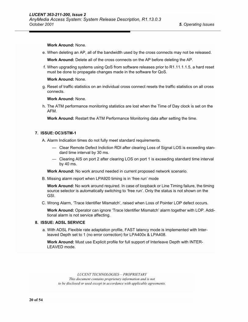
e. When deleting an AP, all of the bandwidth used by the cross connects may not be released.
Work Around: Delete all of the cross connects on the AP before deleting the AP.
f. When upgrading systems using QoS from software releases prior to R1.11.1.1.5, a hard reset must be done to propagate changes made in the software for QoS.
Work Around: None.
g. Reset of traffic statistics on an individual cross connect resets the traffic statistics on all cross connects.
Work Around: None.
h. The ATM performance monitoring statistics are lost when the Time of Day clock is set on the AFM.
Work Around: Restart the ATM Performance Monitoring data after setting the time.
7. ISSUE: OC3/STM-1
A. Alarm Indication times do not fully meet standard requirements.
— Clear Remote Defect Indiction RDI after clearing Loss of Signal LOS is exceeding stan-dard time interval by 30 ms.
— Clearing AIS on port 2 after clearing LOS on port 1 is exceeding standard time interval by 40 ms.
Work Around: No work around needed in current proposed network scenario.
B. Missing alarm report when LPA920 timing is in ‘free run’ mode
Work Around: No work around required. In case of loopback or Line Timing failure, the timing source selector is automatically switching to ‘free run’. Only the status is not shown on the GSI.
C. Wrong Alarm, ‘Trace Identifier Mismatch’, raised when Loss of Pointer LOP defect occurs.
Work Around: Operator can ignore ‘Trace Identifier Mismatch’ alarm together with LOP. Addi-tional alarm is not service affecting.
8. ISSUE: ADSL SERVICE
a. With ADSL Flexible rate adaptation profile, FAST latency mode is implemented with Inter-leaved Depth set to 1 (no error correction) for LPA400x & LPA408.
Work Around: Must use Explicit profile for full support of Interleave Depth with INTER-LEAVED mode.

21 of 54
LUCENT 363-211-200, Issue 2AnyMedia Access System: System Release Description,R1.13.0.3
5. Operating Issues October 2001
LUCENT TECHNOLOGIES — PROPRIETARYThis document contains proprietary information and is not
to be disclosed or used except in accordance with applicable agreements.
9. ISSUE: SDSL
NOTE:With 16 ports provisioned on an LPS716 AP, trainup of SDSL modem may take up to 10 min-utes.
a. LPS716 AP Tip/Ring outputs are UL qualified for intra-building exposure only.
Work Around: If the LPS-716 is to be used with lines that exit the building premises, they must be protected by a Nationally Recognized Testing Laboratory (NRTL) listed telecommuni-cations protection device that provides both primary and secondary protection.
b. Port Test on provisioned LPS716 AP port with no modem will fail with message “Port is busy”.
Work Around: If Port Test is needed, must delete the provisioning for the port (Set port to OOS, click Apply, then click Delete Port in Port Provisioning screen).
c. SDSL PM Threshold Crossing Alert (TCA) is reported with PM data count below threshold value in PM profile assigned to SDSL port.
Work Around: Do not use SDSL PM profile with TCAs enabled.
d. Inventory on SDSL AP’s may not be correct after a system upgrade.
Work Around: Reset the AP to restore inventory information.
10. ISSUE: Telephony/Broadband Interactions
a. ADSL Performance Monitoring reports Errored Seconds and Threshold Crossing Alerts (TCAs) during POTS call processing on LPA404/405 AP
Work Around: TCAs may be avoided by increasing the PM thresholds in the xDSL PM profile.

22 of 54
LUCENT TECHNOLOGIES— PROPRIETARYThis document contains proprietary information and is not
to be disclosed or used except in accordance with applicable agreements.
LUCENT 363-211-200, Issue 2AnyMedia Access System: System Release Description, R1.13.0.3October 2001 6. Modem (CPE) Operating Issues
6. Modem (CPE) Operating Issues
This section contains issues related to specific modems when used to provide ADSL service with the AnyMedia system:
a. ENI 4060 and 5660 modems may lock up when loop is changed. No data service supported.
Work Around: Must disconnect/reconnect cable to modem or power-cycle modem to recover.
b. The ENI 5621 and 3COM Home Connect modems fail the ADSL CRC test in the downstream direction.
Work Around: Run Corrupt CRC test for maximum of 5 seconds. External test equipment may be used to test the integrity of the ADSL link in the downstream direction.
c. Low throughput on ENI 5621 with Default Flexible Profile at loops < 10Kft (3050 m)
Work Around: Create ADSL profile with lower maximum rates for this modem
d. ADSL PM ES hits reported from 5621, 5660, 3COM 918 modems with Default Explicit profile
Work Around: Use Explicit profile with lower maximum rates
e. Downstream SNR and Attenuation reported = 0 with Default Explicit profile on Alcatel-based modem.
Work Around: Use Explicit profile with maximum downstream rate 7424 Kbit/s.
f. ADSL Performance Monitoring reports high Upstream Errored Seconds (ES) with ADSL-LITE profiles on ENI 5621 or 3COM HomeConnect modem.
Work Around: Use Aztech DSL800 or COMTREND CT-500 modem for ADSL-LITE.
g. ADSL Performance Monitoring reports high Upstream ES at 4Kft 26 AWG (1200 m and 0.4 mm wire diameter) on Alcatel SpeedTouch modem with LPA404B AP (NAR).
Work Around: None.
h. Downstream Attenuation reported from Xavi ISDN modem is incorrect.
Work Around: To get correct Attenuation, divide the reported value by 2.
i. ADSL PM reports high Errored Seconds on Xavi ISDN modem with short loops (< 500 feet / 150 m).
Work Around: For short loops, use ADSL transmission profile with 48 in PSDM field.
j. ADSL Performance Monitoring reports high Downstream ES at 8 - 9 Kft (2440 m - 2750 m) onXavi ISDN modem.
Work Around: None.
k. Xavi ISDN modem does not work with Full Explicit Profile.
Work Around: Use Flexible Profile.

23 of 54
LUCENT 363-211-200, Issue 2AnyMedia Access System: System Release Description,R1.13.0.3
6. Modem (CPE) Operating Issues October 2001
LUCENT TECHNOLOGIES — PROPRIETARYThis document contains proprietary information and is not
to be disclosed or used except in accordance with applicable agreements.
l. Xavi ISDN modem has non-conforming cells in QoS feature. Xavi is currently working to resolve this problem. Fix will be delivered as soon as available from Xavi.
Work Around: None.
m. SDSL data may not recover from short (<2 seconds) cable glitch with CellPipe 50S modem.
Work Around: Data recovered by toggling port OOS/in-service, or turning modem on/off.
n. LPA416 link stability (i.e. error performance) may not be optimized with data profile interleave depth set to “1” when using non-Globespan chipset ADSL modems.
Work Around: Increase data profile interleave depth up to a maximum of 64 for non-Globe-span chipset ADSL modems to improve error performance, thereby, reducing probability of link retain.
o. When retrieving data status for ADSL modems with ADI-918 chipsets connected to a LPA416, the downstream attenuation value will be incorrectly displayed as “0”.
Work Around: None.

24 of 54
LUCENT TECHNOLOGIES— PROPRIETARYThis document contains proprietary information and is not
to be disclosed or used except in accordance with applicable agreements.
LUCENT 363-211-200, Issue 2AnyMedia Access System: System Release Description, R1.13.0.3October 2001 7. Turn-Up Procedures
7. Turn-Up Procedures
This section describes the recommended steps to turn-up a new DS3 or E3 system. For the “official” procedure, refer to the Command and Procedures manual (363-211-103). For procedures to turn-up a SONET/SDH system, an E1/DS1 IMA system, Daisy-chained system, ONU subshelf, or for detailed information on QoS provisioning, refer to the Command and Procedures manual.
! WARNING:When removing or inserting a pack always wait 15 seconds before removing or inserting the same or another pack.
NOTE:The procedure described below assumes that initially, no packs have been inserted into the shelf, no cables have been attached to the packs and that the AFM contains software load R1.13.0.3-060nb. If existing AFMs LPA901 or LPA911 are being upgraded to R1.13.0.3, refer to procedures in Section 8 on page 39.
NOTE:The IP address used in this section is assumed to be the LAN (10BaseT) address. For set up of the ATM Operations Channel, refer to Section 8 on page 39.
NOTE:The pull-down menu sequence Provisioning ==> System Turnup ==> Data assumes the 2.2.1 GSI. With the 02.05.03-096 GSI, sequence is Provisioning ==> System Turnup ==> Main Shelf ==> Data
1. Installation of AFM
A. Obtain the default IP address from the AFM. If the IP address is already available, skip to Step B.
— Open a HyperTerminal window on your PC. Under the File-->Properties menu, configure the settings. Set the baudrate of the terminal for 57,600 Bps, Stop Bit to 1, Data to 8 bits, Parity to None, and the Flow Control to none.
— Prior to inserting the AFM into the system, connect the PC running Hyper Terminal (or a dumb terminal) to the console port on the AFM. This requires a straight-through DB9 cable from the COM1 port on the PC to the AFM. While the AFM is initializing, the IP address will appear in the Hyper Terminal window.
— After the IP address appears, remove the cable between the AFM and Hyper Terminal.
B. Plug-in AFM pack into slot marked AP-16/AFM.
— Wait at least 15 minutes for the AFM to complete it initialization. During this time:

25 of 54
LUCENT 363-211-200, Issue 2AnyMedia Access System: System Release Description,R1.13.0.3
7. Turn-Up Procedures October 2001
LUCENT TECHNOLOGIES — PROPRIETARYThis document contains proprietary information and is not
to be disclosed or used except in accordance with applicable agreements.
— If a PC is connected to the console port, the current IP address (e.g., 192.168.160.160)will appear on the terminal connected to the console port in approximately 3 minutes. Once the IP address has been obtained, the connection to the console port may be bro-ken.
— All lights initially are lit on the AFM, then FAULT LED blinks at a 1 per second rate dur-ing initialization. This flashing will last about 5 minutes. FAULT LED may remain on or off for a few minutes during the initialization.
— When initialization has completed the ACTIVE, CR-MJ, and CLF1 LEDs will remain on.
C. Connect the feeder TX output from the Broadband Network (e.g., switch or router) to the RX-1 jack on the AFM pack.
D. Connect the feeder RX output from the Broadband Network (e.g., switch or router) to the TX-1 jack on the AFM pack.
— If the Broadband Network (e.g., switch or router) has been configured correctly, the CR-MJ and CLF-1 LEDs will turn off indicating an active DS3/E3 connection to the switch. This may take up to 3 minutes. If the LEDs do not clear, check the Broadband Network feeder configura-tion.
E. To test the connection to the ATM network (optional):
— Remove RX-1 connection: CLF-1 turns on indicating received loss of signal. After about 10 seconds, CR-MJ LED is lit. Restore RX-1 connection. Observe CR-MJ and CLF-1 LEDs turn off
2. Connecting GSI to System
(assuming latest GSI software is already loaded onto PC - see procedure in Section 9 on page 45)
NOTE:In most GSI screens, there are 3 buttons at bottom. The Apply button sets the provisioning data on the screen, and returns to same screen. The OK button also sets the provisioning data on the screen, but then exits the window. The CANCEL button exits the window. In some screens a CLOSE button appears. This CLOSE button is the same as the CANCEL button.
If Connecting to 10BaseT:
A. Turn on PC.
B. Connect an Ethernet crossover cable with a module RJ45 cable between the GSI PC Ethernet output port to the AFM 10BaseT port. This connection can also be made through a hub. In this case, your PC must be configured with the proper IP address (e.g., If the system IP=192.168.160.160, set the PC IP=192.168.160.X where X is not 160) and subnet mask (e.g., Subnet mask=255.255.255.0).
C. Start-up GSI software by clicking on the GSI Icon.
D. In the Menu bar, click the Connect icon at left. The Connect to Shelf window opens. Select AFM.
— In the Select Link window, select the LAN specified in the work order.

26 of 54
LUCENT TECHNOLOGIES— PROPRIETARYThis document contains proprietary information and is not
to be disclosed or used except in accordance with applicable agreements.
LUCENT 363-211-200, Issue 2AnyMedia Access System: System Release Description, R1.13.0.3October 2001 7. Turn-Up Procedures
— In the Host Address entity enter the default current IP address (obtained in Step 1a, e.g. 192.168.160.160, or as provisioned)
— In the SECURITY ID window enter the security ID: public (or as provisioned)
— Click Connect.
— The AnyMedia AFM ADSL: Graphical System Interface Version 2.2.1, 1.4.17 or 02.03.01 (Shelf View) comes up. Note, the bottom of the GSI states that you are connected to the IP Address of the AFM plug-in. The GSI/AFM are ready for command inputs.
If Connecting to Console:
A. Turn on PC.
B. Connect an RS-232 cable (maximum length 15-feet / 4.5 m) between the GSI PC serial port to the AFM Console port.
C. Start-up GSI software by clicking on the GSI Icon.
D. In the Menu bar, click the Connect icon at left. The Connect to Shelf window opens. Select AFM.
— In the Select Link window, select the COMx specified in the work order.
— In the SECURITY ID window enter the security ID: public (or as provisioned)
— Click Connect.
— The AnyMedia AFM ADSL: Graphical System Interface Version 02.05.03-096, or 02.02.01-162 (Shelf View) comes up. The GSI/AFM are ready for command inputs.
3. Initializing System to Default State (Clearing data memory)
! WARNING:If the AFM is running 1.13.0.3 or later, the Default Router will not change. If the AFM is run-ning an earlier load, after INIT-SYS, the Default Router will be set to 0.0.0.0. If Default Router is needed for remote access, connect GSI via cross-over cable or via console port to AFM and re-provision Default Router. If the AFM is running 1.13.0.3 or later, the Default Router will not change.
A. Execute INITIALIZE SYSTEM DATABASE command:
— From menu bar select NE Operations ==> Initialize System
— In the Initialize System window, check the warning box and hit OK.
— Series of confirmation windows open. Click Yes or OK to confirm command. An hourglass will appear indicating the system is busy. This hourglass will remain until the system initialization is complete. The entire process may take up to 15 minutes.
— In about 2 minutes after start of the initialization, all the AFM LEDs come on for about 20 seconds.
— During the next 5 minutes of initialization, the AFM Fault LED will blink at a 1 per sec-ond rate.

27 of 54
LUCENT 363-211-200, Issue 2AnyMedia Access System: System Release Description,R1.13.0.3
7. Turn-Up Procedures October 2001
LUCENT TECHNOLOGIES — PROPRIETARYThis document contains proprietary information and is not
to be disclosed or used except in accordance with applicable agreements.
— The AFM ACTV light comes up in about 5 minutes. If the ACTV LED is not lit after 20 minutes, remove the AFM and re-insert, then wait another 15 minutes for the ACTV LED to come up.
— Approximately 2 minutes after the AFM ACTV light comes up, the hourglass disappears and the Connect to Shelf window appears at the GSI. When the login is complete, the GSI will show the AFM pack in slot 16.
NOTE:If you cannot connect to the shelf, and the connect command times out, restart the GSI bycompleting Steps 2C and 2D above after closing the GSI window. Return here after you have logged into the system.
4. Verifying Active Software
Verify that the current Active Software is R1.13.0.3-060nb
— From the menu bar select NE Operations ==> Software (or SW Download) ==> Activate
— Verify that the Version Now Running is R1.13.0.3-060nb and that the Version Active After Next Reboot is also R1.13.0.3-060nb If the versions are correct, hit CLOSE.
— If the Version Now Running and the Version Active After Next Reboot is not R1.13.0.3-060nb,check the Version available for Activation.
— If the Version available for Activation is R1.13.0.3-060nb, follow the procedure for Activating Software in Section 8 - Item 6
— If the Version available for Activation is not R1.13.0.3-060nb, follow the procedure in Section 8 - Item 5 to download the correct version of software to the system.
— Hit Cancel to close the window.
5. Setting System Information: Site ID (SID), Contact, and Location
NOTE:The SID, Contact and Location are optional.
To set the System Information:
— From menu bar select Provisioning ==> System Turnup ==> Data ==> Main Shelf
— In the Site ID box enter the site id specified in the work order. (e.g. AnyMedia AFMADSL)
— Leave Contact box blank unless otherwise specified
— In the Location box enter the location specified in the work order. (e.g. LUCENT Technolo-gies)
— Click Apply. A command completed successfully message appears in the AFM Response Monitor.

28 of 54
LUCENT TECHNOLOGIES— PROPRIETARYThis document contains proprietary information and is not
to be disclosed or used except in accordance with applicable agreements.
LUCENT 363-211-200, Issue 2AnyMedia Access System: System Release Description, R1.13.0.3October 2001 7. Turn-Up Procedures
6. Setting Port Numbering Mode
— Enter the Port Numbering Mode as specified in the work order. Note that the AFM will reboot if the Port Numbering Mode is changed.
— Click Apply. A warning message will appear. Click OK.
— The AFM will reboot.
7. Setting Shelf VPIs and Global ATM parameters
To set Shelf VPIs (maximum of 4 supported):
— From menu bar select Provisioning ==> System Turnup ==> Data ==> (tab)Main Shelf
— In the Shelf VP box, click on the default VPI (255). If work order specifies different Shelf VPI(s), enter the VPI specified (e.g., VPI:5). NOTE: this has to match the ATM switch VPI for the DS3/E3 feeder. Select the Service Category (use “UBR” unless specified otherwise).
— Click Add.
— If the default VPI 255 is not specified in work order, it should be deleted.
— Select 255 in the Shelf VP box.
— Click Delete. Enter yes to deletion confirmation message. A command completed successfully message appears in the AFM Response Monitor.
— Repeat Add procedure for all additional Shelf VPIs specified (maximum of 4 supported)
— If ATM Operations Channel is to be used, refer to procedure in Section 7 - Item 9 to set the ATM Operations Channel VPI
— List of Shelf VPIs can be retrieved from menu bar View ==> Data VP Entry Report
To set Global ATM parameters (for details on these parameters, refer to Customer Documentation):
— From menu bar select Provisioning ==> System Turnup ==> Data ==> Main Shelf
— Click Global ATM Parameters
— Review parameters displayed. If service order specifies different parameters for Shelf PCR (Upstream/Downstream) enter those parameters. If service order specifies different parame-ters for Shelf Overbooking Factor/Cell Transfer Delay/Cell Delay Variation/Cell Loss Ratio by Service Category, enter those values.
— Click Apply. A command completed successfully message appears in the AFM Response Monitor.
8. Setting System Security ID (Optional)
! WARNING:AFM must be reset if Security ID is changed.
To set the Security ID:
— From menu bar select Provisioning ==> System Turnup ==> Data ==> Communications

29 of 54
LUCENT 363-211-200, Issue 2AnyMedia Access System: System Release Description,R1.13.0.3
7. Turn-Up Procedures October 2001
LUCENT TECHNOLOGIES — PROPRIETARYThis document contains proprietary information and is not
to be disclosed or used except in accordance with applicable agreements.
— In the Security ID box, enter the Security ID specified in the work order.
— Click Apply.
9. Setting Autonomous Message Destination
(Optional, Used with Element Manager, etc.)
To set the Autonomous Message Destination:
— From the menu bar select Provisioning ==> System Turnup ==> Data ==> Communications
— In the Autonomous Message Destination Text box, type the IP address of the Autonomous Message Destination in the Selected Address box
— Click on Add to add the IP address
— Click on Apply at the bottom to apply changes
10. Setting IP Configuration
(optional operation on new AFM pack - the IP could be the same as the one used to login to the sys-tem). If ATM Operations Channel is to be used, refer to procedure in Section 8 - Item 8.
To set the IP configuration for the LAN:
— From the menu bar select Provisioning ==>System Turnup ==> Data ==> Communications
— In the IP configuration text box enter the 10Base-T IP address specified in the work order (e.g., 135.17.78.37) and note it for reference.
— In the DEFAULT ROUTER text box enter the LAN (10base-T) router address specified in the work order.
— In the SUBNET MASK text box enter the LAN subnet mask address specified in the work order
— Click Apply at bottom to apply changes. A command completed successfully message will appear in the AFM Response Monitor.
— If the 10BaseT IP address is changed, a Disconnect Message will appear. Click OK. The GSI will disconnect automatically. Reconnect to the AFM using the new IP address.
To set the IP configuration for the Console Port:
— From the menu bar select Provisioning ==>System Turnup ==> Data ==>Communications
— In the IP configuration text box enter the Console Port IP address specified in the work order (e.g., 135.17.78.37) and note it for reference.
— In the SUBNET MASK text box enter the subnet mask address specified in the work order
— Click Apply at bottom to apply changes. A command completed successfully message appears in the AFM Response Monitor.

30 of 54
LUCENT TECHNOLOGIES— PROPRIETARYThis document contains proprietary information and is not
to be disclosed or used except in accordance with applicable agreements.
LUCENT 363-211-200, Issue 2AnyMedia Access System: System Release Description, R1.13.0.3October 2001 7. Turn-Up Procedures
11. Setting system date and time
NOTE:After any AFM reboot or shelf power-up, the system date is set back to default of 01/01/70
To set the system date and time:
— AOS-GSI 02.02.01-162: From menu bar select Provisioning ==> Equipment ==> Data ==> Date/Time
— AOS-GSI 02.05.03-096: From menu bar select Provisioning ==> Equipment ==> Date/Time
— The Get Current box shows current AFM date/time. Hit Cancel if date/time not to be changed
— In the Set New box, select “Set to PC date and time” to use date/time from PC, or de-select “Set to PC date and time” and enter date/time you want. Click OK to set date/time and close window
12. Setting the System For Duplex Operation
! WARNING:The AFM in slot 15 must be running 1.13 for it to complete initialization.
A. Install Standby AFM
— Plug-in AFM pack into slot marked AP-15/AFM. All lights initially are lit on the AFMDS3 or AFME3, then FAULT LED blinks at a 1 per second rate until the Duplex provisioning is com-plete and the AFM has completed initialization and the database has been synchronized to the Active AFM.
— Connect the feeder TX output from the splitter to the RX-1 jack on the AFM pack.
— Connect the feeder RX output from the splitter to the TX-1 jack on the AFM pack.
B. Provision the system for Duplex Operation.
— From the menu bar select Provisioning ==> System Turnup ==> Data ==> Main Shelf ==> System Information.
— In the Network Information, Protection Mode Box, select Duplex.
— Click Apply. A warning message will appear. Click Yes. A command completed successfully message will appear in the AFM Response Monitor.
— Within 5 minutes, an AP-1-15 BB-Pack is inserted event message followed by an AP-1-15 BB-Pack is initializing event message will appear.
— Within 5 minutes, an AP-1-15 BB-Pack has initialization has completed event message will appear. If a Minor AFM software version mismatch alarm appears, follow the procedures in Section 8 - Item 6 to activate the current load on the Active AFM.
13. Provisioning the system for service (method defined in work order)
A. Growth of AP Packs: If the work order specifies growth of ADSL or SDSL AP packs, perform the fol-lowing steps:

31 of 54
LUCENT 363-211-200, Issue 2AnyMedia Access System: System Release Description,R1.13.0.3
7. Turn-Up Procedures October 2001
LUCENT TECHNOLOGIES — PROPRIETARYThis document contains proprietary information and is not
to be disclosed or used except in accordance with applicable agreements.
— From menu bar select Provisioning ==> System Turnup ==> Data ==> Pack.
— In the Pack window select the parameters specified in the work order.
— For Pack parameters are:
— Slot Number: AP1 - AP15 (e.g., AP1)
— Pack Type: ADSL or SDSL
— Configured State: In-Service
— Click Add. A Pack Added Successfully message appears in the AFM Response Monitor.
— Repeat steps for each AP to be grown in.
B. Creation of ADSL and SDSL Transmission Profiles
— From menu bar select Provisioning ==> Profiles ==> xDSL Transmission
— There are 8 default ADSL Transmission Profiles. The first 4 Default profiles may be used for non-QoS lines. The other 4 Default profiles in the list are for use with QoS.
— There are also 3 default SDSL Transmission Profiles
— View the parameters for each of the default transmission profiles by selecting in the Profile box. If one of the default profiles is specified in the work order or if one of them contains the values listed in the work order, select the CANCEL button at the bottom of the screen to exit this window. If none of the default profiles will meet the parameters listed in the work order, a new profile must be created. To create a new profile, use the following procedure:
— Select the Default profile with Rate Adaptation matching the work order. For example, if ADSL profile with Explicit Rate Adaptation is needed, select Default 4. Click New at the bottom of the window. New xDSL Transmission Profile screen is displayed.
— Fill in the windows according to your work order.
— Click the Create Profile button
— The new profile will be displayed in the Transmission Profiles screen.
— Note the number (and name/label if entered) of new xDSL Transmission profile (e.g., 5).
— If any other profiles are needed, repeat last 5 steps. If no new profiles are needed, hit Cancel to close the window.
C. Performance Monitoring (PM) Profile: There are 4 default profiles, labeled “1-Default1: All TCAs Dis-abled”, “2-Default2: TCAs Enabled”, “127-Default2: SDSL TCAs Enabled” and “128-Default1: All SDSL TCAs Disabled”. Profiles 1 and 2 are for ADSL AP packs. Profiles 127 and 128 are for SDSL AP packs. The profile “Default1” collects PM data, but will not send Threshold Crossing Alerts (TCAs). If the work order specifies setting PM parameters, perform the following steps:
— From menu bar select Provisioning ==> Profiles ==> xDSL Performance Monitoring
— In the “PM Profile” box select “Default2” for ADSL or SDSL as appropriate.

32 of 54
LUCENT TECHNOLOGIES— PROPRIETARYThis document contains proprietary information and is not
to be disclosed or used except in accordance with applicable agreements.
LUCENT 363-211-200, Issue 2AnyMedia Access System: System Release Description, R1.13.0.3October 2001 7. Turn-Up Procedures
— Compare the values displayed with the work order. If the values listed match those dis-played with the work order, close this window. If any values need to be changed, use the following procedure to create a new PM profile.
— Click New at the bottom of the window. New PM Profile screen opens.
— Enter new upstream/downstream values from the work order.
— Click Create Profile.
— The new profile will be displayed.
— Note the name and number of new PM profile (e.g., 3).
— Click Cancel to close window (or repeat steps if more PM profiles needed).
D. Creation of ATM Traffic Profiles (for Cross-Connect Provisioning)
— From menu bar select Provisioning ==> Profiles ==> ATM Traffic
— There are 8 default ATM Traffic profiles. The first 4 Default profiles are to be used for each of the 4 classes of service on ADSL lines. The last 4 Default profiles in list are for SDSL lines.
— View the parameters for each of the default transmission profiles by selecting in the Profile Name box. If one of the default profiles is specified in the work order or if one of them contains the values listed in the work order, select the CANCEL button at the bot-tom of the screen to exit this window. If none of the default profiles will meet the param-eters listed in the work order, a new profile must be created. To create a new profile, use the following procedure:
— Select the Default profile with Service Category matching the work order. For example, if ATM Traffic profile for ADSL with CBR is needed, select Default 2. Click New at the bottom of the window. New ATM Traffic Profile screen is dis-played.
— Fill in the windows according to your work order. Include a Profile Name.
— Click the Create Profile button
— A Successfully Setting up ATM Profile message appears in the AFM Response Monitor.
— If any other profiles are needed, repeat last 4 steps. If no new profiles are needed, hit Cancel to close the window.
E. Feeder Provisioning (DS3/E3): If the work order specifies to set feeder port, and feeder port parame-ters, perform the following steps:
— From menu bar select Provisioning ==>System Turnup ==> Data ==> (Tab) Feeder
— In the Feeder Port box, select Port 1 and verify the parameters displayed. If only one Feeder Port is to be used, it should be Feeder Port 1. Feeder Port 2 is configured in Daisy Chain applications.
— In the Feeder Port Parameters list boxes, start with the default parameters provided and change only those parameters specified in the work order.

33 of 54
LUCENT 363-211-200, Issue 2AnyMedia Access System: System Release Description,R1.13.0.3
7. Turn-Up Procedures October 2001
LUCENT TECHNOLOGIES — PROPRIETARYThis document contains proprietary information and is not
to be disclosed or used except in accordance with applicable agreements.
! WARNING:Parameters MUST match router or switch configuration! In particular, verify cell scrambling setting in DS3 or E3, and Frame Format in DS3.
— SET FEEDER PORT PARAMETERS: DS3 version
— Configuration Status: In-Service (provisionable only for Port 2)
— Timing Source: Free Running or Line Timed. If the timing source is Line Timed, the Network Timing Reference to those AP’s supporting Network Timing Refer-ence is from the AFM. If the Timing Source is Free Running, the Network Timing Source is from the COMDAC.
— Cell Scrambling: Enabled or Disabled
— Line Type: C Bit Parity
— Single Bit Error Correction: Enabled or Disabled
— Frame Format: PLCP or HEC
— Line Length: 0-224 or 225-450
— Provision Timing Source: Free Running or Line Time
— Performance Monitor Threshold - If Feeder PM is desired, click PM Enable box then select Performance Monitoring Thresholds box and fill in the parameters according to the work order. Otherwise, leave blank.
— If changes made, click Apply. A series of messages appear in the AFM Response Monitor.
NOTE:Cannot set Timing Source for Port 2
— If Feeder Port 2 is enabled, connect feeder cables from RX-2/TX-2 jacks on the AFM to corre-sponding TX-1/RX-1 jack on the downstream (daisy-chained) AnyMedia AFM.
— SET FEEDER PORT PARAMETERS: E3 version
— Configuration Status: Enabled (provisionable only for Port 2)
— Timing Source: Free Running or Line Timed.
— Cell Scrambling: Enabled or Disabled
— Single Bit Error Correction: Enabled or Disabled
— Frame Format: HEC (not provisionable)
— Provision Timing Source: Free Running or Line Time
— Trailtrace Alarm Enable: true or false
— Performance Monitor Threshold - If Feeder PM is desired, click PM Enable box then select Performance Monitoring Thresholds box and fill in the parameters according to the work order. Otherwise, leave blank.

34 of 54
LUCENT TECHNOLOGIES— PROPRIETARYThis document contains proprietary information and is not
to be disclosed or used except in accordance with applicable agreements.
LUCENT 363-211-200, Issue 2AnyMedia Access System: System Release Description, R1.13.0.3October 2001 7. Turn-Up Procedures
— If changes made, click Apply. A series of messages appear in the AFM Response Monitor.
— Repeat for Port 2 (Daisy Chain configuration) if specified in the work order.
— If Feeder Port 2 is enabled, connect feeder cables from RX-2/TX-2 jacks on the AFM to corresponding TX-1/RX-1 jacks on the downstream (daisy-chained) Any-Media AFM.
NOTE:Cannot set Timing Source for Port 2
— If Feeder Port 2 is enabled, connect feeder cables from RX-2/TX-2 jacks on the AFM to corre-sponding TX-1/RX-1 jack on the downstream (daisy-chained) AnyMedia AFM.
F. Provision IMA Services (LPA941/LPA942 AFM)
• Set IMA Timing Source:
— Select the Provision->Equipment->Feeder Menu from the GSI toolbar
— Click on the Timing Source sub-tab
— Select the E1/DS1 feeders for Primary and Secondary timing source if values other than the defaults are desired (Primary = E1/DS1 Feeder 1, Secondary = E1/DS1 Feeder 2)
— Click on the Apply button. Wait for the process to complete
• Set E1 Feeders to In-Service:
— Select the Main Shelf Turnup – System provisioning screen
— Click on the Feeder Port sub-tab
— For each feeder port to be provisioned, select the port number and change the Administrative Port State to IS
— Click on the Apply button and wait for the process to complete. Do not check the PM Enable box during this step. PM should not be enabled until all IMA provi-sioning is completed
— Note - a feeder port must be provisioned to IS before it can be added to the IMA Group
• Provision IMA Group:
— Select the main IMA tab, then select the IMA Group sub-tab
— Select the desired values for the IMA Group Configuration values. Note - Timingmode must be set to CTC
— Click on the Create Group button. Wait for the process to complete
• Add IMA links:
— Select the IMA Link sub-tab from the same screen
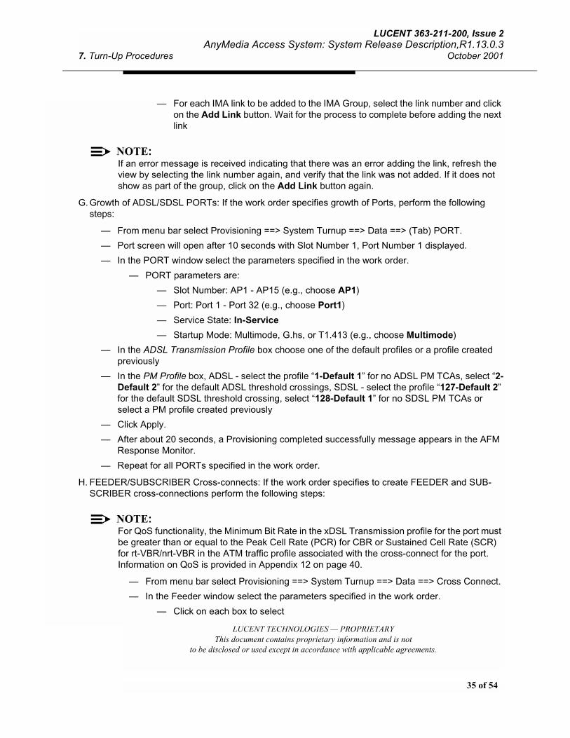
35 of 54
LUCENT 363-211-200, Issue 2AnyMedia Access System: System Release Description,R1.13.0.3
7. Turn-Up Procedures October 2001
LUCENT TECHNOLOGIES — PROPRIETARYThis document contains proprietary information and is not
to be disclosed or used except in accordance with applicable agreements.
— For each IMA link to be added to the IMA Group, select the link number and click on the Add Link button. Wait for the process to complete before adding the next link
NOTE:If an error message is received indicating that there was an error adding the link, refresh the view by selecting the link number again, and verify that the link was not added. If it does not show as part of the group, click on the Add Link button again.
G. Growth of ADSL/SDSL PORTs: If the work order specifies growth of Ports, perform the following steps:
— From menu bar select Provisioning ==> System Turnup ==> Data ==> (Tab) PORT.
— Port screen will open after 10 seconds with Slot Number 1, Port Number 1 displayed.
— In the PORT window select the parameters specified in the work order.
— PORT parameters are:
— Slot Number: AP1 - AP15 (e.g., choose AP1)
— Port: Port 1 - Port 32 (e.g., choose Port1)
— Service State: In-Service
— Startup Mode: Multimode, G.hs, or T1.413 (e.g., choose Multimode)
— In the ADSL Transmission Profile box choose one of the default profiles or a profile created previously
— In the PM Profile box, ADSL - select the profile “1-Default 1” for no ADSL PM TCAs, select “2-Default 2” for the default ADSL threshold crossings, SDSL - select the profile “127-Default 2”for the default SDSL threshold crossing, select “128-Default 1” for no SDSL PM TCAs or select a PM profile created previously
— Click Apply.
— After about 20 seconds, a Provisioning completed successfully message appears in the AFM Response Monitor.
— Repeat for all PORTs specified in the work order.
H. FEEDER/SUBSCRIBER Cross-connects: If the work order specifies to create FEEDER and SUB-SCRIBER cross-connections perform the following steps:
NOTE:For QoS functionality, the Minimum Bit Rate in the xDSL Transmission profile for the port must be greater than or equal to the Peak Cell Rate (PCR) for CBR or Sustained Cell Rate (SCR) for rt-VBR/nrt-VBR in the ATM traffic profile associated with the cross-connect for the port. Information on QoS is provided in Appendix 12 on page 40.
— From menu bar select Provisioning ==> System Turnup ==> Data ==> Cross Connect.
— In the Feeder window select the parameters specified in the work order.
— Click on each box to select

36 of 54
LUCENT TECHNOLOGIES— PROPRIETARYThis document contains proprietary information and is not
to be disclosed or used except in accordance with applicable agreements.
LUCENT 363-211-200, Issue 2AnyMedia Access System: System Release Description, R1.13.0.3October 2001 7. Turn-Up Procedures
— For FEEDER parameters (set according to DS3/E3 switch):
- VPI: (e.g., 5) - if VP-only cross-connect, this not one of the Shelf VPs
- VCI: (e.g., 33) - valid range = 33 - 1999 (max. 1023 with 900/910 AFM) - if VP-only cross-connect, VCI blank
— For SUBSCRIBER parameters (set according to mode/type of modem):
- Slot Number:AP1 - AP15 (e.g., choose AP1)
- Port:PORT1 - PORT32 (e.g., choose Port1)
- VPI: (Provided in the work order, e.g. use 0 for bridged mode with 3COM modem)
- VCI: (Provided in the work order, e.g. use 33 for bridged mode with 3COM modem)
— For ATM Traffic Profile, select from the list in the Profile box.
— If work order specifies identifier for the cross-connect, enter text in the optional Circuit ID box
— Click Connect. A Cross Connect completed successfully message appears in the AFM Response Monitor.
— Repeat for all cross-connects specified in work order.
— When all the cross-connects have been created, verify that they are correct by clicking “View All Cross Connects” and reviewing the information.
— When done reviewing cross-connects, hit Cancel to close screen
14. Installation of ADSL or SDSL AP packs
NOTE:Software Download Status indication (LED) When an ADSL AP is software downloaded, the software download complete event appears before the ADSL AP Fault LED stops blinking.
A. Locate the AP slot specified in work order.
B. Remove the tip/ring cable from cable holder panel and remove the cable holder panel.
C. Plug-in the AP pack into the AP slot.
— Verify on pack insertion that the LED blinks for 5 - 30 seconds (LED is lit steady for 10 sec-onds on LPS716 AP) on a pack with software on it (about 5 minutes for one with no software), then the light goes out. If the Fault LED remains lit, there could be a non-service affecting fail-ure. Remove and reinsert the AP. Wait until the LED has stopped blinking. If the LED still is lit, consult the Alarms section of the AnyMedia Access System Commands and Procedures for Data Services Manual.
D. There will be a Major (MJ) alarm displayed on the AFM pack.
E. Connect tip/ring cable to the AP pack. Major alarm clears.

37 of 54
LUCENT 363-211-200, Issue 2AnyMedia Access System: System Release Description,R1.13.0.3
7. Turn-Up Procedures October 2001
LUCENT TECHNOLOGIES — PROPRIETARYThis document contains proprietary information and is not
to be disclosed or used except in accordance with applicable agreements.
F. To verify Pack status at GSI, go to View ==> Data Status
G. Select Pack (e.g., AP-1). Slot Operational Status should be Equipped, Pack Operational Status should be In Service. If not, wait 5 minutes and repeat.
H. If AP not reported In Service, remove pack then re-insert. Wait 5 more minutes, then check Pack/Port status as above.
15. Modem Connection
A. Connect modems to provisioned ports on AP. Wait few minutes for modem train-up. Note, SDSL ports may take up to 30 minutes to go in-service.
B. To verify Port status at GSI, go to View ==> Data Status
C. Select Pack (e.g., AP-1) and Port (e.g., Port1).
— Port status and Transmission Conditions will be reported within 1 minute
! WARNING:If SDSL modem fails to train-up, check for correct polarity on Tip/Ring cable.
D. If the AP is reported In Service but the Port Operational Status is Out of Service, verify that the con-nection to the modem is correct. If it is correct, attempt to bring the port into service by toggling the port. This is done by the following procedure:
— From menu bar select Provisioning ==> System Turnup ==> Data ==> (Tab) PORT.
— In the PORT window select the parameters specified in the work order.
— For PORT parameters:
- Slot Number: AP1 - AP15, Select the affected pack
- Port: Port 1 - Port 16, Select the affected port
- Service State: Out of Service
— Click Apply.
— Repeat Port provisioning setting port In Service as follows:
— For PORT parameters:
- Slot Number: AP1 - AP15, Select the affected pack
- Port: Port 1 - Port 32, Select the affected port
- Service State: In Service
— Click Apply.
— Wait 5 minutes. Retrieve PACK/PORT status as described above. If the PORT status is still Out of Service, Power Cycle the modem. Wait 5 minutes. Retrieve PACK/PORT status. The PORT status should now be In Service
— Repeat for all modems on pack

38 of 54
LUCENT TECHNOLOGIES— PROPRIETARYThis document contains proprietary information and is not
to be disclosed or used except in accordance with applicable agreements.
LUCENT 363-211-200, Issue 2AnyMedia Access System: System Release Description, R1.13.0.3October 2001 7. Turn-Up Procedures
16. Checking system is free of alarms
A. If Active Alarms screen is open, check for alarms. If not, hit Retrieve/Show Alarms icon on Menu bar or select Fault ==> Alarms. There should be no active alarms displayed. If any alarms appear, con-sult the Alarms section of the AnyMedia Access System Commands and Procedures for Data Ser-vices Manual for information on clearing the alarms.

39 of 54
LUCENT 363-211-200, Issue 2AnyMedia Access System: System Release Description,R1.13.0.3
8. Operational and Maintenance Procedures October 2001
LUCENT TECHNOLOGIES — PROPRIETARYThis document contains proprietary information and is not
to be disclosed or used except in accordance with applicable agreements.
8. Operational and Maintenance Procedures
This section contains procedures to perform normal operational or maintenance actions.
! WARNING:When removing or inserting a pack, always wait 15 seconds before removing or inserting the same or another pack.
1. Growth of an ADSL or SDSL AP pack
A. Provision the AP slot/ports as per above procedures.
B. Locate the AP slot specified in work order.
C. Remove the tip/ring cable from cable holder panel and remove the cable holder panel.
D. Plug-in the appropriate AP pack type into the AP slot.
— Verify on pack insertion the FAULT LED lights momentarily
— Wait at least 5 minutes and verify that all pack LEDs are OFF
E. Connect tip/ring cable to the AP pack. Alarm for Tip/Ring Cable disconnect will clear.
2. Degrowth of an ADSL or SDSL AP pack
A. From menu bar select Provisioning ==> System Turnup ==> Data ==> (tab) PACK
— In the Pack window select the parameters specified in the work order.
— Pack parameters are:
— Slot Number: AP1 - AP15 (e.g., AP1)
— Pack Type: ADSL or SDSL
— Configured State: Out of Service
— Click Apply
— After about 40 seconds, a provisioning completed successfully message appears in the AFM Response Monitor.
— In the Pack window, delete the Out of Service pack by hitting Delete
— A confirmation message appears. Click Yes in confirmation box. After about 40 seconds, a pack deleted successfully message appears at the AFM Response Monitor.
B. Disconnect tip/ring cable from AP specified in work order
C. Remove AP pack specified in work order
D. Insert cable holder panel into AP slot and insert tip/ring cable into panel
E. Major (MJ) alarm will be reported for AP Pack Removal. This alarm may be cleared by selecting the alarm in the GSI Alarm screen (click on “mj” at left), then hit “Clear BB Alarm”.

40 of 54
LUCENT TECHNOLOGIES— PROPRIETARYThis document contains proprietary information and is not
to be disclosed or used except in accordance with applicable agreements.
LUCENT 363-211-200, Issue 2AnyMedia Access System: System Release Description, R1.13.0.3October 2001 8. Operational and Maintenance Procedures
F. If system is equipped with a COMDAC, clear pack missing alarm at COMDAC using ED-CONFIG command:
— From menu bar select TL1 COMMANDS ==> ALL COMMANDS ==> ED ==> CONFIG
— In the ED-CONFIG window select: AP-1-{slot # pack removed from} and NR (not required)
— Hit YES when ask to confirm command.
3. Migration of AP packs
To change a slot equipped an AP to one equipped with an AP supporting a greater number of ports (e.g. LPA408 to and LPA416):
A. Remove the existing AP and insert the new AP. Ports previously provisioned will recover.
B. If specified in the service order, provision the additional ports. Use procedures from Section 7.
To change a slot equipped with an AP to a slot equipped with an AP supporting a fewer number of ports (e.g. LPA416 to LPA408), the additional ports must be deleted (if provisioned)
C. From menu bar select Provisioning ==> System Turnup ==> Data ==> (Tab) PORT.
D. Port screen will open after 10 seconds with Slot Number 1, Port Number 1 displayed.
E. In the PORT window select the parameters for port being deleted
— PORT parameters are:
— Slot Number: AP1 - AP15 (e.g., choose AP1)
— Port: Port 1 - Port 32 (e.g., choose Port5)
— Service State: Out of Service
F. Click Apply. A provisioning completed successfully message will appear in the AFM Response Moni-tor.
G. To delete the OOS port, hit Delete Port. Click Yes at Confirmation. a port deleted successfully mes-sage will appear at the AFM Response Monitor.
H. Repeat for other ports requiring deletion
I. Remove the existing AP and insert the new AP. Ports provisioned for service will recover.
4. Determining operational status of ADSL or SDSL AP pack and ports
A. From the menu bar select View ==> Data Status
B. Enter AP slot number in Pack field
C. Verify pack operational status of the added AP pack is In Service
D. Enter Port number in Port field
E. Verify port operational status of the added port is In Service
F. Observe SNR Margin, Attenuation, and Transmit Rate is reported in Upstream and Downstream directions.

41 of 54
LUCENT 363-211-200, Issue 2AnyMedia Access System: System Release Description,R1.13.0.3
8. Operational and Maintenance Procedures October 2001
LUCENT TECHNOLOGIES — PROPRIETARYThis document contains proprietary information and is not
to be disclosed or used except in accordance with applicable agreements.
G. Repeat for each port/pack
5. Downloading AFM Software
! WARNING:During software download, the AFM does not respond/responds slowly to commands (e.g., blank screen is displayed after GSI logon from another PC).
! WARNING:You must use 02.05.03-096 or 02.02.01-162GSI to download any R1.13.0.3 software
A. Check that you are running GSI 02.05.03-096, or 02.02.01-162 from the about GSI tab. Update the GSI if you are running an earlier version. Note: Remove the old GSI before installation of the new one - refer to procedures in Section 9.
B. Obtain a CD-ROM with the correct AFM software, R1.13.0.3-060nb.
C. Follow directions with the CD-ROM to download the software into a directory on the PC.
D. From the menu bar, select NE Operations ==> Software (or SW Download) ==> Download
E. In the “Download Software From” box, browse to the directory with the software load.
F. Double-click on the “version.txt” file. Verify that the software version is correct in the Selected SW Version box. The second line should say LPA901/LPA911 R1.13.0.3-060nb.
G. Click on the Download Only button and click OK to begin the Software Download. The software download will take approximately 45 minutes.
H. At the GSI, an FTP window will appear with a progress bar. When the progress bar is completed, the software download is complete. Close the software download window.
6. Activate AFM Software
Simplex
A. From the menu bar, select NE Operations ==> Software (or SW Download) ==> Activate
B. Verify that the software load listed in the box labeled Version Available for Activation is the software desired.
C. Click on the Activate Software button. Progress bar opens at bottom of display. Activation should take about 5 minutes. When the Activation is complete, “Software Activation Complete” message reported at bottom of display. If the AFM is currently running 1.13 software, the activate procedure automatically reboots the AFM. In this case, the GSI will disconnect. When the connect window appears, reconnect to the AFM.
D. From the menu bar, select NE Operations ==> Software (or SW Download) ==> Activate
E. Verify the new software load is reported in the Version Active After Next Reboot box. If the new soft-ware is also reported in the Version currently active box, the software upgrade is complete. There is no need to reboot the system. Hit Cancel. If the new software is not also reported in the Version cur-rently active box, a reboot is required for the system to be running the new software.
42 of 54
LUCENT TECHNOLOGIES— PROPRIETARYThis document contains proprietary information and is not
to be disclosed or used except in accordance with applicable agreements.
LUCENT 363-211-200, Issue 2AnyMedia Access System: System Release Description, R1.13.0.3October 2001 8. Operational and Maintenance Procedures
Duplex
A. From the menu bar, select NE Operations ==> Software (or SW Download) ==> Activate
B. Verify that the software load is listed in one of the boxes on either the Active or Standby AFM.
C. Verify that the service state of the non-Active AFM is Standby.
D. Click on the button to the left of the software version to be activated.
E. Click on the Activate button at the bottom of the window.
F. Click Apply. A confirmation window will appear. Click Yes. A series of messages will appear at the bottom of the Activation window indicating the progress of the activation. A series of status conditions will also appear in the Alarms window indicating the status of the activation process.
G. When the activation is complete, the standby AFM will reboot. After completion the reboot, the sys-tem will do a protection switch. At this point, the system is operating on the new load. After the pro-tection switch, the newly standby AFM will reboot.
7. To reboot the system:
02.02.01-162 GSI: From the menu bar select NE Operations ==> AFM Reboot
02.05.03-096 GSI: From the menu bar select NE Operations ==> SW Download ==> AFM Reboot
— If hard reset is required (service-affecting), click the Hard Reset box.
— In a Duplex system, select whether the active or standby AFM is to be rebooted. If the active AFM is selected, the system will perform a protection switch when the active AFM is rebooted.
— In the Reboot window, click Reboot Now.
— All LEDs on the AFM pack come on for a few seconds. During initialization, the AFM FAULT LED blinks at a 1 per second rate.
— When initialization has completed, the AFM ACTV LED will remain on. Initialization takes approximately 5 minutes.
— After about 2 minutes, the Connect Window will appear (Simplex only). Put the Security ID “public” (or as provisioned) in the Connect To Shelf window and click connect.
8. Setting up an ATM Operations Channel
! WARNING:RFC1483 routed encapsulation LLC snap is required on the network side in order to commu-nicate with the in-band management channel on the AFM. Neither a Bridge Router nor a Pro-tocol Converter such as the AC-60 or SA-600 can be used.
! WARNING:The ATM Operations Channel has a Service Class of rtVbr. The network side MUST be set up with same Service Class for the ATM Operations Channel to function. Note, the Service Class for the ATM Operations Channel is reported in the System VP Entries report (Select Provi-sioning ==> Equipment ==> System VP Entries).

43 of 54
LUCENT 363-211-200, Issue 2AnyMedia Access System: System Release Description,R1.13.0.3
8. Operational and Maintenance Procedures October 2001
LUCENT TECHNOLOGIES — PROPRIETARYThis document contains proprietary information and is not
to be disclosed or used except in accordance with applicable agreements.
A. Create the Network Module and configure the Network Management System at network side.
B. To set the Operations Channel VPI/VCI:
— From menu bar select Provisioning ==>System Turnup ==> Data ==> Main Shelf ==> (Tab) Main Shelf
— Click Global ATM Parameters tab
— Enter the ATM Operations Channel VPI and VCI specified in the Work Order. Note, the Oper-ations Channel VPI does not have to be the same as the Shelf VPI.
— Click Apply.
C. Determine an IP address for the AFM ATM Operations Channel (and COMDAC if the In-Band Man-agement Channel will be used for access to the COMDAC. The AFM and COMDAC 10Base-T port addresses should be in the same subnet).
D. Using local access, log into the AFM and provision the AFM communication parameters.
— From the menu bar select Provisioning ==> System Turnup ==> Data ==> Main Shelf ==> (Tab) Communications
— In the IP configuration text box enter the ATM IP address previously determined and note it for reference. Select ATM. A dot appears next to ATM and the Default Router should be grayed out.
— At the bottom of the screen, click on OK. This runs for about 90 seconds.
E. If the In-Band Management Channel is to be used for the COMDAC, log into the COMDAC using local access and provision the IP address.
— Use SET-IP command to set IP address and Default Router. The IP address should be on same subnet as the AFM. The default Router must be the AFM 10BaseT IP address.
F. Connect a crossover 9-pin, 10Base-T cable from the AFM to the LAN port of the system.
! WARNING:Clear all interface alarms before attempting to access the AFM or COMDAC.
G. Both the AFM and the COMDAC can now be accessed through the In-Band Channel.
9. Changing ADSL/SDSL Transmission Profile on a Port
! WARNING:To be compliant with ATM Traffic Management 4.0, when changing ADSL transmission profile for a port, the cross-connect must be deleted and a new cross-connect created. This is accomplished automatically when the port is deleted.
To change the profile assigned to a port, first retrieve the cross-connect information for the port, set the port to OOS, delete the port, set the port in-service with a new profile number, then provision the cross-connect(s).
44 of 54
LUCENT TECHNOLOGIES— PROPRIETARYThis document contains proprietary information and is not
to be disclosed or used except in accordance with applicable agreements.
LUCENT 363-211-200, Issue 2AnyMedia Access System: System Release Description, R1.13.0.3October 2001 8. Operational and Maintenance Procedures
A. Retrieve the cross-connect for the port
— From the menu bar, select Provisioning ==> System Turnup ==> Data ==> (tab) Cross Connect
— Hit View All Cross Connects to get the parameters
— Note which cross connects are assigned to the port
B. Change port to OOS
— From menu bar select Provisioning ==> System Turnup ==> Data ==> (Tab) PORT
— Select Slot Number and Port
— Set Service State to Out of Service.
— Click Apply. A provisioning completed successfully message appears in the AFM Response Monitor.
— To delete the port, click Delete port. A Confirmation message appears. Click Yes. A port deleted successfully appears in the AFM Response Monitor.
C. Change Transmission Profile number, then set port in-service
— In Port screen, select new Transmission Profile number from pull-down list (if a new profile is needed, use procedure from Section 7 - Item 13 to create profiles)
— Set Service State for Port to In-Service
— Click Apply. A provisioning completed successfully message appears in the AFM Response Monitor.
D. Re-enter the cross-connect(s) for the port
— From menu bar select Provisioning ==> System Turnup ==> Data ==> (tab) Cross Connect
— Enter Feeder and Subscriber parameters for the port
— Hit Connect. A provisioning completed successfully message appears in the AFM Response Monitor.

45 of 54
LUCENT 363-211-200, Issue 2AnyMedia Access System: System Release Description,R1.13.0.3
9. Software Upgrade Procedures October 2001
LUCENT TECHNOLOGIES — PROPRIETARYThis document contains proprietary information and is not
to be disclosed or used except in accordance with applicable agreements.
9. Software Upgrade Procedures
This section describes the recommended steps to convert a system running any previous release to Release 1.13.0.3. Before download of new software, the GSI must be upgraded.
! WARNING:The GSI must be upgraded to version 02.05.03-096 or 02.02.01-162 before downloading R1.13.0.3-060nb software. This GSI MUST be used only for Download/Activate/Reboot until software upgrade has been completed.
! WARNING:Software Download may occasionally fail. If Download failure observed as indicated by FTP failure message or no load displayed in Version Available for Activation field in Activate screen, rerun the Software Download.
1. To upgrade the GSI:
— Always uninstall old GSI first. After downloading the GSI, create shortcut to the executable:
02.02.01-162 (Build - 162) GSI = C:\ProgramFiles\AnyMedia\GSI\gsi.exe
02.05.03-096 (Build - 096 GSI = C:\ProgramFiles\AnyMedia\GSI\gsi.exe
2. Downloading AFM Software
! WARNING:During software download, the AFM does not respond/responds slowly to commands (e.g., blank screen is displayed after GSI logon from another PC).
! WARNING:You must use 02.05.03-096 or 02.02.01-162GSI to download any R1.13.0.3 software
A. Check that you are running GSI 02.05.03-096, or 02.02.01-162 from the about GSI tab. Update the GSI if you are running an earlier version. Note: Remove the old GSI before installation of the new one - refer to procedures in Section 9.
B. Obtain a CD-ROM with the correct AFM software, R1.13.0.3-060nb.
C. Follow directions with the CD-ROM to download the software into a directory on the PC.
D. From the menu bar, select NE Operations ==> Software (or SW Download) ==> Download
E. In the “Download Software From” box, browse to the directory with the software load.
F. Double-click on the “version.txt” file. Verify that the software version is correct in the Selected SW Version box. The second line should say LPA901/LPA911 R1.13.0.3-060nb.
G. Click on the Download Only button and click OK to begin the Software Download. The software download will take approximately 15 minutes.
46 of 54
LUCENT TECHNOLOGIES— PROPRIETARYThis document contains proprietary information and is not
to be disclosed or used except in accordance with applicable agreements.
LUCENT 363-211-200, Issue 2AnyMedia Access System: System Release Description, R1.13.0.3October 2001 9. Software Upgrade Procedures
H. At the GSI, an FTP window will appear with a progress bar. When the progress bar is completed, the software download is complete.
3. Activate AFM Software
Simplex
A. From the menu bar, select NE Operations ==> Software (or SW Download) ==> Activate
B. Verify that the software load listed in the box labeled Version Available for Activation is the software desired.
C. Click on the Activate Software button. Progress bar opens at bottom of display. Activation should take about 5 minutes. When the Activation is complete, “Software Activation Complete” message reported at bottom of display. If the AFM is currently running 1.13 software, the activate procedure automatically reboots the AFM. In this case, the GSI will disconnect. When the connect window appears, reconnect to the AFM.
D. From the menu bar, select NE Operations ==> Software (or SW Download) ==> Activate
E. Verify the new software load is reported in the Version Active After Next Reboot box. If the new soft-ware is also reported in the Version currently active box, the software upgrade is complete and there is no need to reboot the system. If the new software is not reported in the Version currently active box, the AFM must be rebooted (step 4). Hit Cancel.
Duplex
A. From the menu bar, select NE Operations ==> Software (or SW Download) ==> Activate
B. Verify that the software load is listed in one of the boxes on either the Active or Standby AFM.
C. Verify that the service state of the non-Active AFM is Standby or Mismatch of Equipment.
D. Click on the button to the left or right of the software version to be activated.
E. Click on the Activate button at the bottom of the window.
F. Click Apply. A confirmation window will appear. Click Yes. A series of messages will appear at the bottom of the Activation window indicating the progress of the activation. A series of status conditions will also appear in the Alarms window indicating the status of the activation process.
G. When the activation is complete, the standby AFM will reboot. After completion the reboot, the sys-tem will do a protection switch. At this point, the system is operating on the new load. After the pro-tection switch, the newly standby AFM will reboot.
4. To reboot the system (needed only when upgrading from releases prior to 1.13):
02.02.01-162 GSI: From the menu bar select NE Operations ==> AFM Reboot
02.05.03-096 GSI: From the menu bar select NE Operations ==> SW Download ==> AFM Reboot
— If hard reset is required (service-affecting), click the Hard Reset box.
— In the Reboot window, click Reboot Now.
47 of 54
LUCENT 363-211-200, Issue 2AnyMedia Access System: System Release Description,R1.13.0.3
9. Software Upgrade Procedures October 2001
LUCENT TECHNOLOGIES — PROPRIETARYThis document contains proprietary information and is not
to be disclosed or used except in accordance with applicable agreements.
— All LEDs on the AFM pack come on for a few seconds. During initialization, the AFM FAULT LED blinks at a 1 per second rate.
— When initialization has completed, the AFM ACTV LED will remain on. Initialization takes approximately 5 minutes.
— After about 2 minutes, the Connect Window will appear. Put the Security ID “public” (or as provisioned) in the Connect To Shelf window and click connect.
5. Upgrade of AP software:
When system is running with the new load, the APs may start AP software download. This is indi-cated by the appearance of BB-AP software download in progress events. At the completion of the AP software downloads, BB-AP software download completed event messages will be reported, fol-lowed by AP pack initialization event messages.

48 of 54
LUCENT TECHNOLOGIES— PROPRIETARYThis document contains proprietary information and is not
to be disclosed or used except in accordance with applicable agreements.
LUCENT 363-211-200, Issue 2AnyMedia Access System: System Release Description, R1.13.0.3October 2001 10. Glossary
10. Glossary
ADSL Asymmetric Digital Subscriber Line
AEM AnyMedia Element Manager
AFM ATM Feeder Multiplexer
AOS-BB AnyMedia Access System Operations Software for Broadband Services
AOS-GSI AnyMedia Access System Operations Software for Graphical System Interface
AOS-NB AnyMedia Access System Operating Software for Narrowband Services
AP Application Pack
ATM Asynchronous Transfer Mode
BAIU Broadband Access Interface Unit
BER Bit Error Rate
BIST Built-In Self test
CAC Connection Admission Control
CBR Constant Bit Rate
COMDAC Common Data And Control Pack
CP Circuit Pack
CPE Customer Premises Equipment
DMT Discrete Multi-Tone
DS3 Digital Signal Level Three
E3 European Digital Signal Level Three
FAST Flexible Access Subscriber Terminal
FCM Fuse Control Module
FTP File Transfer Protocol
GA General Availability
GSI Graphical System Interface
HBER High Bit Error Rate
IMA Inverse Multiplexing over ATM
ISDN Integrated Services Digital Network
LAN Local Area Network
LOF Loss of Frame

49 of 54
LUCENT 363-211-200, Issue 2AnyMedia Access System: System Release Description,R1.13.0.3
10. Glossary October 2001
LUCENT TECHNOLOGIES — PROPRIETARYThis document contains proprietary information and is not
to be disclosed or used except in accordance with applicable agreements.
LOS Loss Of Signal
MEA Mismatch of Equipment and Attributes
MLT Mechanized Loop Testing
NVDS Non-Volatile Data Storage
OAP Optical Application Pack
OCP Optical Controller Pack
PCR Peak Cell Rate
POTS Plain Old Telephone Service
PPP Point-to-Point Protocol
QoS Quality of Service
R&R Remove and Reset
SDSL Symmetric Digital Subscriber Line
SNR Signal-to-Noise Ratio
STM-1 Synchronous Transport Module Level 1
TCA Threshold Crossing Alert
UBR Unspecified Bit Rate
VCI Virtual Channel Identifier
VPI Virtual Path Identifier
xDSL Digital Subscriber Line (ADSL, SDSL, e.g.)

50 of 54
LUCENT TECHNOLOGIES— PROPRIETARYThis document contains proprietary information and is not
to be disclosed or used except in accordance with applicable agreements.
LUCENT 363-211-200, Issue 2AnyMedia Access System: System Release Description, R1.13.0.3October 2001 11. Appendix - QoS/Connection Admission Control
11. Appendix - QoS/Connection Admission Control
Connection Admission Control (CAC) determines if a requested connection can be provisioned with assurance that the service can be provided. UBR connections are always accepted by the CAC.
Three parameters determine the shelf capacity used in the CAC algorithm: Shelf PCR, the Minimum Bit Rate of the subscriber interface, and the Shelf Overbooking Factors.
The Shelf Peak Cell Rate (PCR) is the maximum bandwidth in cells per second a shelf can guaran-tee. In a single shelf system, this value can be the default, which is also the maximum, i.e., the full bandwidth of the feeder interface to the ATM network. When the Shelf PCR is lower than the feeder bandwidth, the remaining bandwidth can still be used by Unspecified Bit Rate (UBR) traffic. (In fact, UBR traffic can use any bandwidth not currently in use by other connections with more stringent QoS.) One value specifies the upstream rate and one value specifies the downstream rate.
The Minimum Bit Rate (upstream and downstream) specified in the transmission profile is the mini-mum rate at which the link (ADSL or SDSL) will train. The customer loop qualification tests should give a good indication of this value.
This Minimum Bit Rate is used in determining whether a new connection can be admitted to the shelf.For a CBR, VBR or nrt-VBR connection, the Minimum Bit Rate must be able to support the PCR of the connection as well as any existing connections.
An approximate conversion factor that can be used in this calculation is:
2.5 Minimum Bit Rate in kilobit per sec. (Kbit/s) ( ( PCR/Shelf Overbooking Factor (cells per sec.)
A transmission profile is applied to a port during port provisioning. Note that the creation of the profile and the port provisioning may be accepted, but a connection using the profile may be rejected. The parameters must be chosen to be compatible with the planned service and the modem to be used.
The Shelf Overbooking Factor is a measure of the level of statistical multiplexing in the system. This factor multiplies the Shelf PCR and the Minimum Bit Rate when the CAC determines if a new connec-tion can be admitted to the shelf. Separate factors apply to the four service classes: Constant Bit Rate (CBR), real time Variable Bit Rate (rt-VBR), non-real time VBR (nrt-VBR) and UBR. An exam-ple of how this parameter functions is as follows:
When the overbooking factor for CBR, nrt-VBR and rt-VBR is 2, connections will be accepted until one of these conditions fails:
1. The total bandwidth required [sum of all PCRs (for CBR connections) and all SCRs (for VBR con-nections)] by these connections does not exceed twice the shelf PCR and

51 of 54
LUCENT 363-211-200, Issue 2AnyMedia Access System: System Release Description,R1.13.0.3
11. Appendix - QoS/Connection Admission Control October 2001
LUCENT TECHNOLOGIES — PROPRIETARYThis document contains proprietary information and is not
to be disclosed or used except in accordance with applicable agreements.
2. The total bandwidth required [sum of all PCRs (for CBR connections) and all SCRs (for VBR con-nections)] by all connections on a subscriber line does not exceed twice the Minimum Bit Rate of the port.
The larger the Shelf Overbooking Factor, the better the network is utilized but the greater the risk for congestion, which may result in cells to be dropped. The values selected for the overbooking factor may need to be tuned after monitoring the ATM Traffic statistics. If congestion is being encountered too frequently, provisioning needs to be adjusted to relieve it.
If congestion is localized to a port, increasing the Minimum Bit Rate of the port can provide more bandwidth for those connections. All cross connects on a port must be deleted before changing any parameters in the port profile. It is recommended that a new port profile be created with the new parameters, since the profile may be in use on other ports. Once the port is provisioned with the new profile, the cross connects can be re-created.
If congestion is general to the shelf, it may be desirable to reduce the Shelf Overbooking Factors. Reduction of an overbooking factor will be rejected if it is reduced below the level needed to accom-modate existing connections. In this case, connections may need to be moved to a new line, possi-bly a new shelf before the overbooking factor can be reduced.

52 of 54
LUCENT TECHNOLOGIES— PROPRIETARYThis document contains proprietary information and is not
to be disclosed or used except in accordance with applicable agreements.
LUCENT 363-211-200, Issue 2AnyMedia Access System: System Release Description, R1.13.0.3October 2001 12. Appendix - GSI PPP Activation
12. Appendix - GSI PPP Activation
1. Requirements for GSI PPP services:
A. NT 4.0 platform
• NT 4.0 Service Pack 4 or later
• Download the latest NT service packs from:
http://www.microsoft.com/ntserver/nts/downloads/default.asp
B. For WIN 95:
• Install Microsoft Dialup Networking 1.3 or later
• DUN13.exe can be found in the GSI directory and is distributed with the GSI
C. For WIN 98 and 2000, and the above platforms
• Install the GSI 02.02.01-162 or 02.05.03-096
2. Service Activation on the PC:
To activate the PPP support for the GSI requires the following to be installed the first time on your system:
NOTE:Windows NT4.0 Security does not allow the automatic/programmatic installation of these com-ponents without the involvement of User/Administrator of the system. This is the reason the GSI installation program does not complete these steps automatically.
1. Install a modem-like device which will support the serial connection between the GSI and the COMDAC/AFM. This device file has been copied to your system by the GSI installation.
• At PC, from Control Panel, click on Modems.
• Click “Add”, then select “Don’t detect my modem” and click “Next”
• Select “AnyMedia GSI” and “PPP Connection”
• Select COM1 and click “Next”, then click ‘Finish”
• On Modem window, select “Properties”.
• Select Maximum speed: 19200, then click Connection tab
• Verify settings “8, None, 1” then click Advanced
• Verify “Use flow control” should be off, click on “Record a log file”, click OK
2. For NT 4.0 and WIN 2000, must Install/Activate the Remote Access Service if not already installed in your system
• At PC, from Control Panel, click on Network
• If Remote Access Service does not appear in the list, click “Add”

53 of 54
LUCENT 363-211-200, Issue 2AnyMedia Access System: System Release Description,R1.13.0.3
12. Appendix - GSI PPP Activation October 2001
LUCENT TECHNOLOGIES — PROPRIETARYThis document contains proprietary information and is not
to be disclosed or used except in accordance with applicable agreements.
— Select “Remote Access Service” and click OK. Restart system if prompted
• If Remote Access Service appears in list, select it and click “Properties”
• If “PPP Connection” appears in list, click Cancel because the Connection exists. Otherwise, click “Add”
• If the “PPP Device” is already installed, it will appear in list of “RAS Capable Devices”. Select it and click OK. Otherwise, click “Install Modem” and run procedure in step 1 above.

54 of 54
LUCENT TECHNOLOGIES— PROPRIETARYThis document contains proprietary information and is not
to be disclosed or used except in accordance with applicable agreements.
LUCENT 363-211-200, Issue 2AnyMedia Access System: System Release Description, R1.13.0.3October 2001 12. Appendix - GSI PPP Activation