anthony liftgates, inc. installation · anthony liftgates, inc. ... for magnum tuckunder tm...
TRANSCRIPT
Anthony Liftgates, Inc.
1037 W. Howard Street • P.O. Box 615 • Pontiac, IL 61764-0615
Ph: 815.842.3383 • Fax: 815.844.3612 • Toll Free: 800.482.0003
www.anthonyliftgates.comL-401
Revision 09/15
A N T H O N Y L I F T G A T E S , I N C .
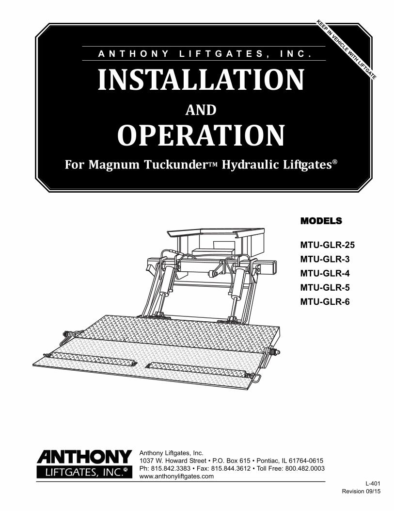
INSTALLATIONAND
OPERATIONFor Magnum TuckunderTM Hydraulic Liftgates®
KEEP
IN V
EHIC
LE W
ITH LIFTG
ATE
MMOODDEELLSS
MTU-GLR-25
MTU-GLR-3
MTU-GLR-4
MTU-GLR-5
MTU-GLR-6

General Information Section
Introduction . . . . . . . . . . . . . . . . . . . . . . . . . . . . . . . . 3
Nomenclature . . . . . . . . . . . . . . . . . . . . . . . . . . . . . . 5
General Information . . . . . . . . . . . . . . . . . . . . . . . . . 6
Installation Section
General Installation Information . . . . . . . . . . . . . . . 8
Installation Procedure . . . . . . . . . . . . . . . . . . . . . . 10
Final Inspection Checklist . . . . . . . . . . . . . . . . . . . 27
Decals. . . . . . . . . . . . . . . . . . . . . . . . . . . . . . . . . . . . 28
Operation Section
General Safety Operating Instructions . . . . . . . . . 33
Operating Instructions . . . . . . . . . . . . . . . . . . . . . . 35
Maintenance Section
Quick Check Maintenance Guide . . . . . . . . . . . . . 36
Maintenance Procedures . . . . . . . . . . . . . . . . . . . . 37
Safety Section
Safety . . . . . . . . . . . . . . . . . . . . . . . . . . . . . . . . . . . . 41
Troubleshooting Section
Troubleshooting Guide. . . . . . . . . . . . . . . . . . . . . . 45
815-842-3383 1 Anthony Liftgates, Inc.
Contents
Attention!
The success or failure of this equipment could very well depend on the proper installationof the liftgate. Read and understand the contents of these instructions before proceeding!
Important
When installed, this liftgate must not alter or prevent vehicle compliance to any existingstate or federal standards and especially FMVSS 108. Each chassis manufacturers rec-ommendations should be consulted for compliance.
Note to Installers!
Read the operating instructions and maintenance guide before installing the unit to famil-iarize yourself with its operation.
Important Operation Notes
A restraining system may be needed to retain certain types of cargo on the liftgate platform,depending upon the specific application, such as a cart stop, retention ramp, fencing,straps, etc. This should be considered by the purchaser for their particular application soas to prevent the possibility of severe personal injury or death due to cargo shifting and/orfalling from the liftgate platform.
All users of this liftgate must be 21 years of age and have read and understood all opera-tion instruction booklets and decals before use.
Anthony Liftgates, Inc. 2 815-842-3383
Congratulations on selecting an AnthonyLiftgates Magnum Tuckunder liftgate.Anthony liftgates are among the finest lift-gates available on the market today. Toensure your liftgate will perform to yourexpectations we have provided the follow-ing manuals, designed to provide you withthe necessary instructions and safety pre-cautions to install and operate theTuckunder models of Anthony liftgates.
1. Installation, Operation, Troubleshooting,and Maintenance manual forMTU-GLR Model Tuckunder Liftgates(MTU-GLR-IO).
2. Parts manual for MTU-GLR ModelTuckunder Liftgates (MTU-GLR-P).
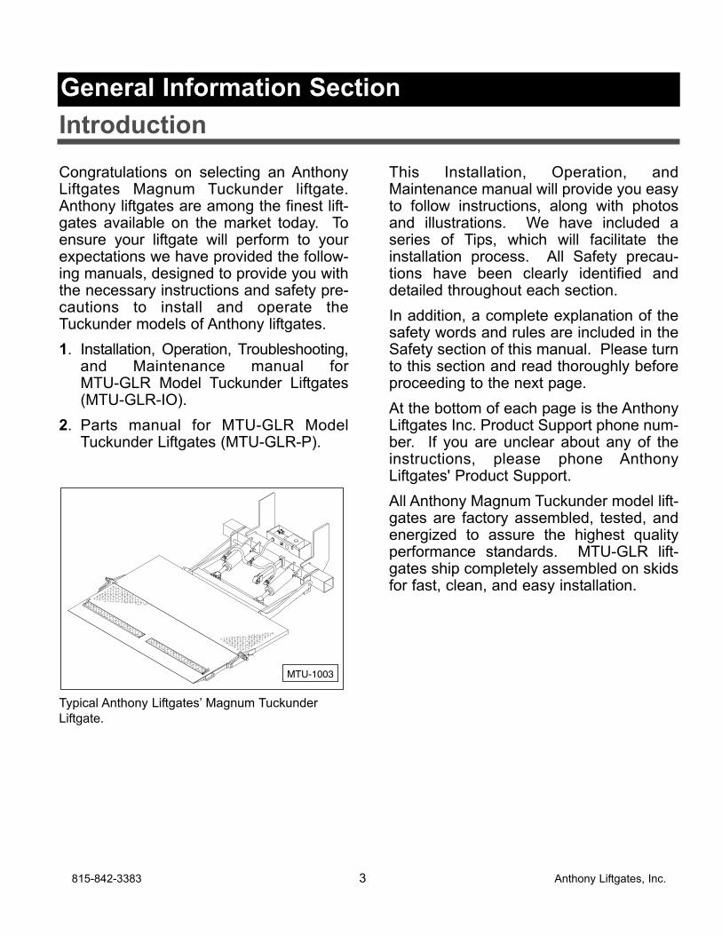
Typical Anthony Liftgates’ Magnum Tuckunder
Liftgate.
This Installation, Operation, andMaintenance manual will provide you easyto follow instructions, along with photosand illustrations. We have included aseries of Tips, which will facilitate theinstallation process. All Safety precau-tions have been clearly identified anddetailed throughout each section.
In addition, a complete explanation of thesafety words and rules are included in theSafety section of this manual. Please turnto this section and read thoroughly beforeproceeding to the next page.
At the bottom of each page is the AnthonyLiftgates Inc. Product Support phone num-ber. If you are unclear about any of theinstructions, please phone AnthonyLiftgates' Product Support.
All Anthony Magnum Tuckunder model lift-gates are factory assembled, tested, andenergized to assure the highest qualityperformance standards. MTU-GLR lift-gates ship completely assembled on skidsfor fast, clean, and easy installation.
MTU-1003
815-842-3383 3 Anthony Liftgates, Inc.
Introduction
General Information Section
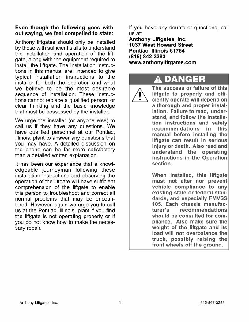
Even though the following goes with-out saying, we feel compelled to state:
Anthony liftgates should only be installedby those with sufficient skills to understandthe installation and operation of the lift-gate, along with the equipment required toinstall the liftgate. The installation instruc-tions in this manual are intended to givetypical installation instructions to theinstaller for both the operation and whatwe believe to be the most desirablesequence of installation. These instruc-tions cannot replace a qualified person, orclear thinking and the basic knowledgethat must be possessed by the installer.
We urge the installer (or anyone else) tocall us if they have any questions. Wehave qualified personnel at our Pontiac,Illinois, plant to answer any questions thatyou may have. A detailed discussion onthe phone can be far more satisfactorythan a detailed written explanation.
It has been our experience that a knowl-edgeable journeyman following theseinstallation instructions and observing theoperation of the liftgate will have sufficientcomprehension of the liftgate to enablethis person to troubleshoot and correct allnormal problems that may be encoun-tered. However, again we urge you to callus at the Pontiac, Illinois, plant if you findthe liftgate is not operating properly or ifyou do not know how to make the neces-sary repair.
If you have any doubts or questions, callus at:Anthony Liftgates, Inc.1037 West Howard StreetPontiac, Illinois 61764(815) 842-3383www.anthonyliftgates.com
Anthony Liftgates, Inc. 4 815-842-3383
The success or failure of thisliftgate to properly and effi-ciently operate will depend ona thorough and proper instal-lation. Failure to read, under-stand, and follow the installa-tion instructions and safetyrecommendations in thismanual before installing theliftgate can result in seriousinjury or death. Also read andunderstand the operatinginstructions in the Operationsection.
When installed, this liftgatemust not alter nor preventvehicle compliance to anyexisting state or federal stan-dards, and especially FMVSS105. Each chassis manufac-turer’s recommendationsshould be consulted for com-pliance. Also make sure theweight of the liftgate and itsload will not overbalance thetruck, possibly raising thefront wheels off the ground.
DANGER
815-842-3383 5 Anthony Liftgates, Inc.
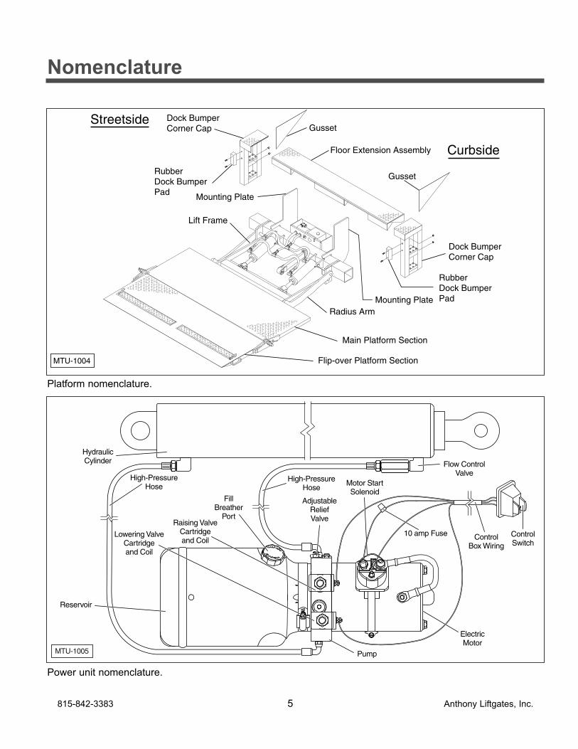
Mounting Plate
Main Platform Section
GussetRubber Dock BumperPad
Gusset
Rubber Dock BumperPad
Floor Extension Assembly
Dock Bumper Corner Cap
Dock Bumper Corner Cap
Mounting Plate
Curbside
Streetside
Flip-over Platform Section
Lift Frame
Radius Arm
MTU-1004
Platform nomenclature.
Nomenclature
MTU-1005
High-PressureHose
High-PressureHose
Flow ControlValve
ControlBox Wiring
Pump
AdjustableReliefValve
10 amp Fuse
Motor StartSolenoid
Lowering ValveCartridgeand Coil
Raising ValveCartridgeand Coil
HydraulicCylinder
FillBreather
Port
Reservoir
ControlSwitch
ElectricMotor
Power unit nomenclature.
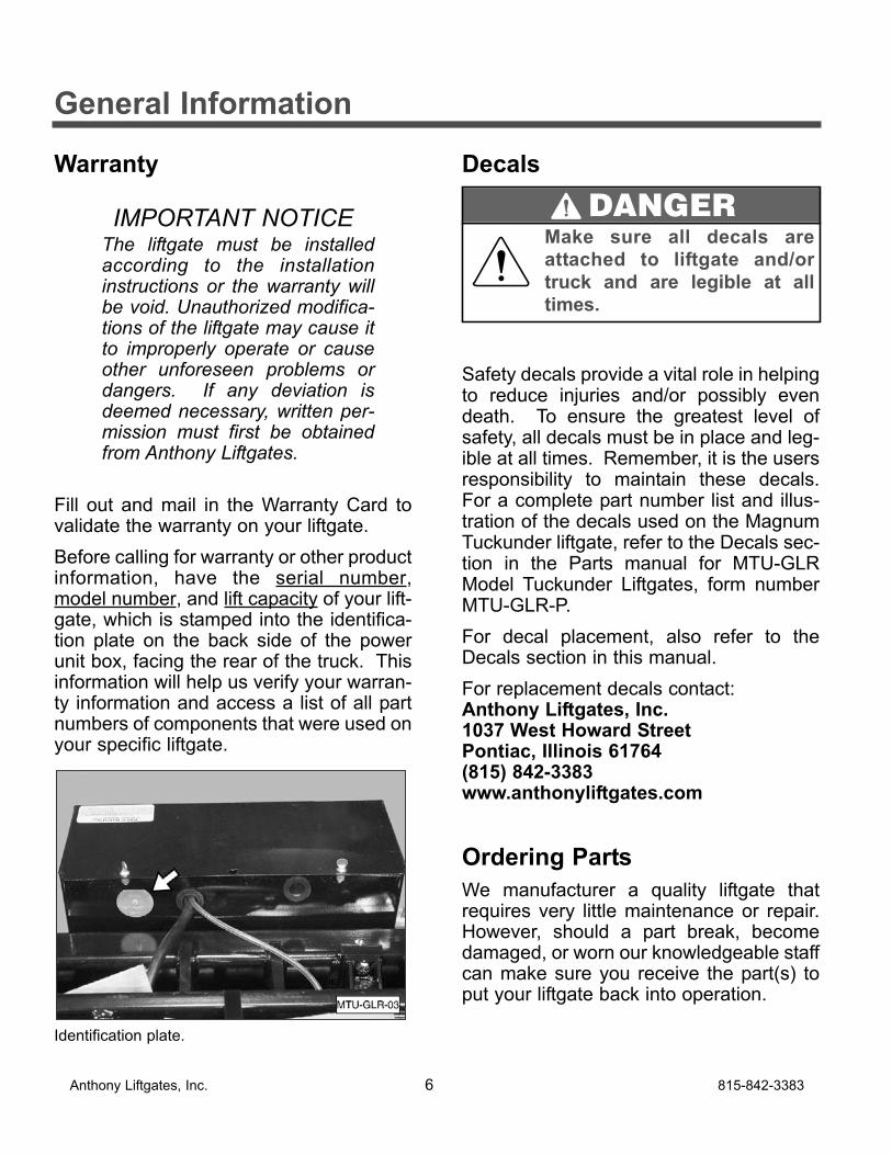
Warranty
IMPORTANT NOTICEThe liftgate must be installedaccording to the installationinstructions or the warranty willbe void. Unauthorized modifica-tions of the liftgate may cause itto improperly operate or causeother unforeseen problems ordangers. If any deviation isdeemed necessary, written per-mission must first be obtainedfrom Anthony Liftgates.
Fill out and mail in the Warranty Card tovalidate the warranty on your liftgate.
Before calling for warranty or other productinformation, have the serial number,model number, and lift capacity of your lift-gate, which is stamped into the identifica-tion plate on the back side of the powerunit box, facing the rear of the truck. Thisinformation will help us verify your warran-ty information and access a list of all partnumbers of components that were used onyour specific liftgate.
Identification plate.
Decals
Safety decals provide a vital role in helpingto reduce injuries and/or possibly evendeath. To ensure the greatest level ofsafety, all decals must be in place and leg-ible at all times. Remember, it is the usersresponsibility to maintain these decals.For a complete part number list and illus-tration of the decals used on the MagnumTuckunder liftgate, refer to the Decals sec-tion in the Parts manual for MTU-GLRModel Tuckunder Liftgates, form numberMTU-GLR-P.
For decal placement, also refer to theDecals section in this manual.
For replacement decals contact:Anthony Liftgates, Inc.1037 West Howard StreetPontiac, Illinois 61764(815) 842-3383www.anthonyliftgates.com
Ordering Parts
We manufacturer a quality liftgate thatrequires very little maintenance or repair.However, should a part break, becomedamaged, or worn our knowledgeable staffcan make sure you receive the part(s) toput your liftgate back into operation.
Anthony Liftgates, Inc. 6 815-842-3383
General Information
Make sure all decals are
attached to liftgate and/or
truck and are legible at all
times.
DANGER
For questions or to order parts, contact:Anthony Liftgates, Inc.1037 West Howard StreetPontiac, Illinois 61764(815) 842-3383www.anthonyliftgates.com
Tooling Required
The following is a list of suggested toolsthat should be used to install the MagnumTuckunder liftgate.
• Overhead Crane or Forklift
• Mig or Stick Welder
• Heavy-Duty C-Clamps
• Tape Measure
• Level (small, magnetic)
• Cutting Torch (in some applications)
815-842-3383 7 Anthony Liftgates, Inc.
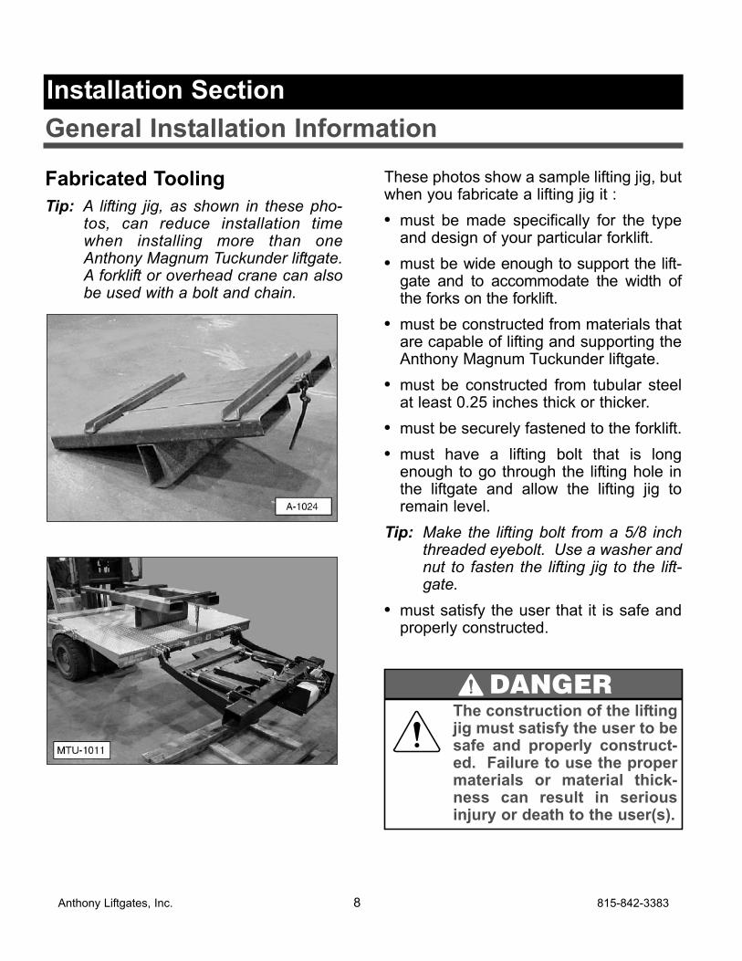
Fabricated Tooling
Tip: A lifting jig, as shown in these pho-tos, can reduce installation timewhen installing more than oneAnthony Magnum Tuckunder liftgate.A forklift or overhead crane can alsobe used with a bolt and chain.
These photos show a sample lifting jig, butwhen you fabricate a lifting jig it :
• must be made specifically for the typeand design of your particular forklift.
• must be wide enough to support the lift-gate and to accommodate the width ofthe forks on the forklift.
• must be constructed from materials thatare capable of lifting and supporting theAnthony Magnum Tuckunder liftgate.
• must be constructed from tubular steelat least 0.25 inches thick or thicker.
• must be securely fastened to the forklift.
• must have a lifting bolt that is longenough to go through the lifting hole inthe liftgate and allow the lifting jig toremain level.
Tip: Make the lifting bolt from a 5/8 inchthreaded eyebolt. Use a washer andnut to fasten the lifting jig to the lift-gate.
• must satisfy the user that it is safe andproperly constructed.
Anthony Liftgates, Inc. 8 815-842-3383
General Installation Information
Installation Section
The construction of the liftingjig must satisfy the user to besafe and properly construct-ed. Failure to use the propermaterials or material thick-ness can result in seriousinjury or death to the user(s).
DANGER
Prior To Installation1. Place the truck on a flat, level surface.
Block the wheels to prevent the truckfrom moving while installing a liftgate.
2. The dimensions on the following chartare to only be used as a guide for whatcan be expected for clearances need-ed. They DO NOT have to be exact,unless you are near the extreme highor low-end of the bed height mountingrange. The most important dimensionto aim for is the "B" dimension. Theothers can vary and should not alterthe functionality of the liftgate.
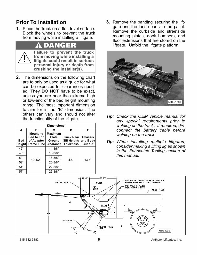
3. Remove the banding securing the lift-gate and the loose parts to the pallet.Remove the curbside and streetsidemounting plates, dock bumpers, andfloor extensions that are stored on theliftgate. Unfold the liftgate platform.
Tip: Check the OEM vehicle manual forany special requirements prior towelding on the truck. If required, dis-connect the battery cable beforewelding on the truck.
Tip: When installing multiple liftgates,consider making a lifting jig as shownin the Fabricated Tooling section ofthis manual.
815-842-3383 9 Anthony Liftgates, Inc.
Dimensions
A B C D EMounting Maximum
Bed to Top Plate Truck Rear ChassisBed of Adapter Ground Sill Height/ and Body
Height Frame Tube Clearance Thickness Cut out
46” 14-3/8”
48” 16-3/8”
50” 18-3/8”
52” 20-3/8”
54” 22-3/8”
57” 25-3/8”
MTU-1036
Failure to prevent the truckfrom moving while installing aliftgate could result in seriouspersonal injury or death fromcrushing the installer(s).
DANGER
19-1/2” 4.5” 13.5”
Step 1Remove the cover from the power unitbox. Remove all the parts and installationinstructions from inside the box. Someunits are shipped from the factory with ashipping plug in the power unit reservoir. Ifnecessary, replace the shipping plug witha vent plug.
Tip: The power unit box should containplastic tie wraps for battery cable,two stop brackets, one latch plate,one 150 Amp circuit breaker, andone package containing decals,shims, and manuals.
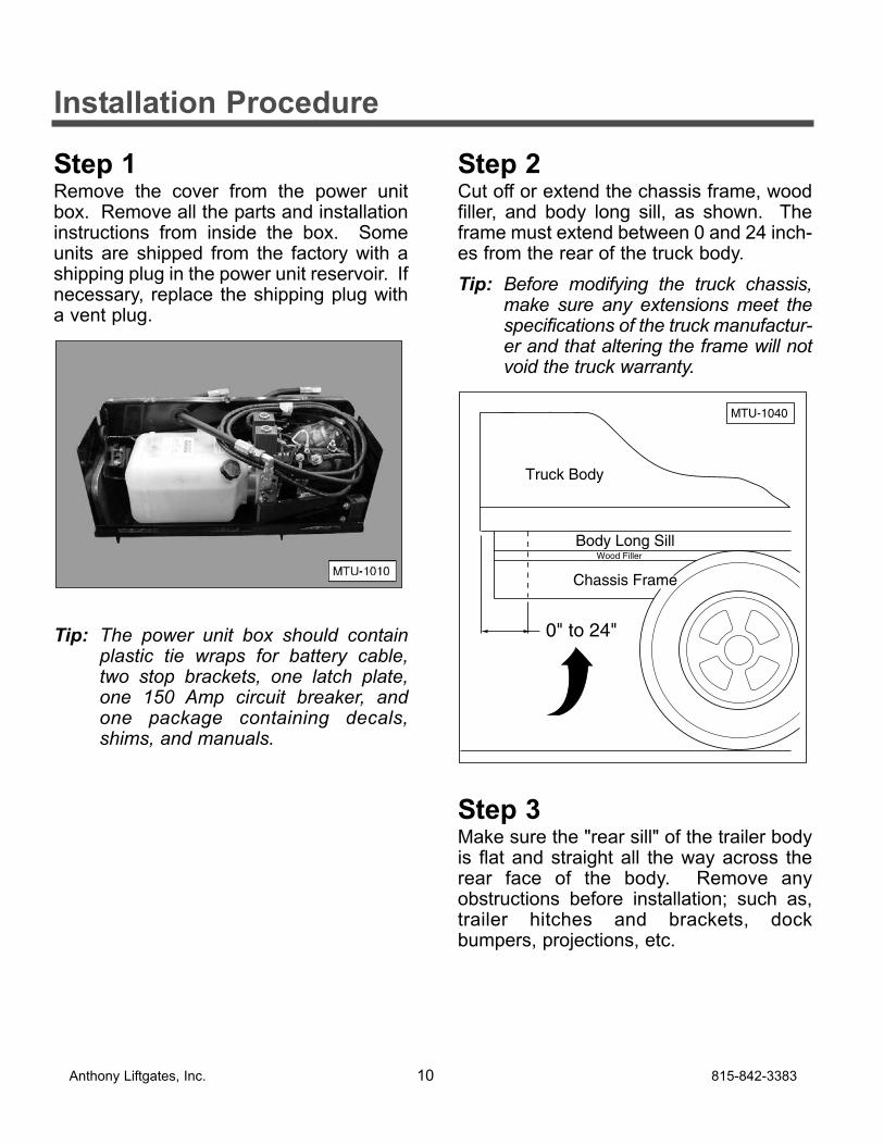
Step 2Cut off or extend the chassis frame, woodfiller, and body long sill, as shown. Theframe must extend between 0 and 24 inch-es from the rear of the truck body.
Tip: Before modifying the truck chassis,make sure any extensions meet thespecifications of the truck manufactur-er and that altering the frame will notvoid the truck warranty.
Step 3Make sure the "rear sill" of the trailer bodyis flat and straight all the way across therear face of the body. Remove anyobstructions before installation; such as,trailer hitches and brackets, dockbumpers, projections, etc.
0" to 24"
Body Long SillWood Filler
Chassis Frame
MTU-1040
Truck Body
Anthony Liftgates, Inc. 10 815-842-3383
Installation Procedure
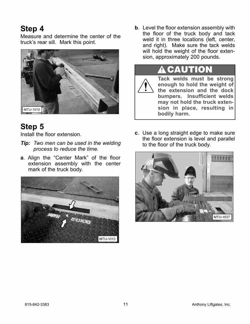
Step 4Measure and determine the center of thetruck’s rear sill. Mark this point.
Step 5Install the floor extension.
Tip: Two men can be used in the weldingprocess to reduce the time.
a. Align the “Center Mark” of the floorextension assembly with the centermark of the truck body.
b. Level the floor extension assembly withthe floor of the truck body and tackweld it in three locations (left, center,and right). Make sure the tack weldswill hold the weight of the floor exten-sion, approximately 200 pounds.
c. Use a long straight edge to make surethe floor extension is level and parallelto the floor of the truck body.
815-842-3383 11 Anthony Liftgates, Inc.
Tack welds must be strongenough to hold the weight ofthe extension and the dockbumpers. Insufficient weldsmay not hold the truck exten-sion in place, resulting inbodily harm.
CAUTION
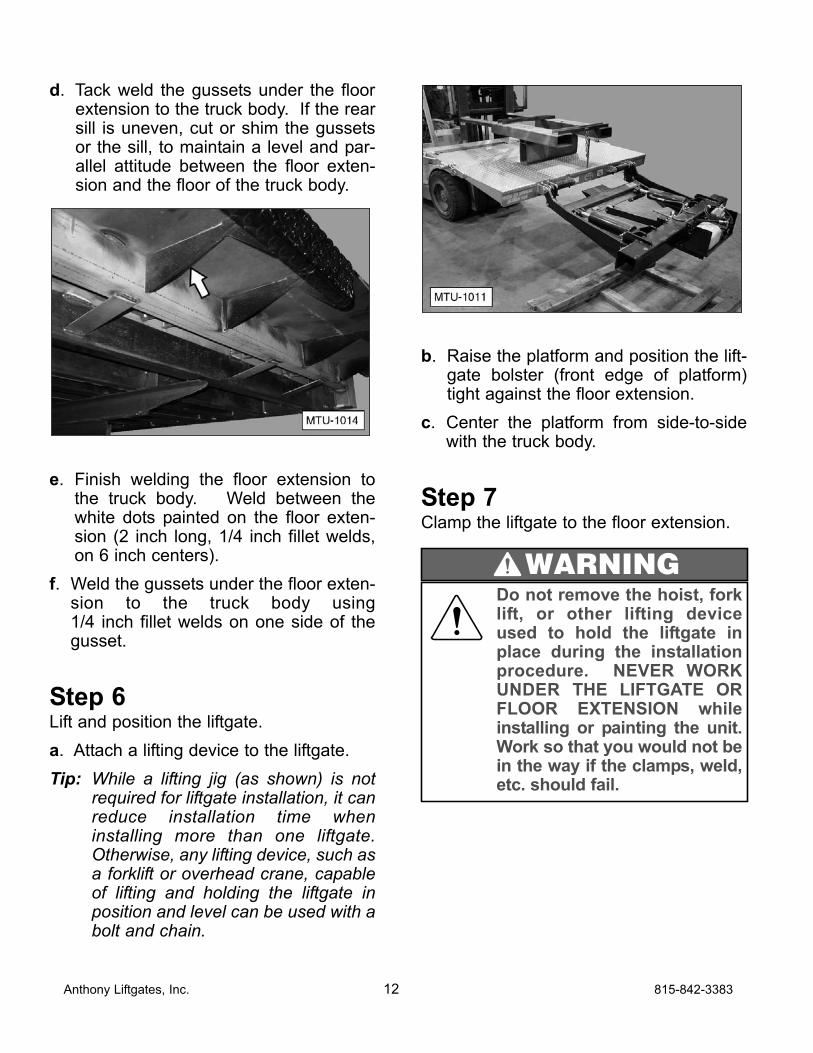
d. Tack weld the gussets under the floorextension to the truck body. If the rearsill is uneven, cut or shim the gussetsor the sill, to maintain a level and par-allel attitude between the floor exten-sion and the floor of the truck body.
e. Finish welding the floor extension tothe truck body. Weld between thewhite dots painted on the floor exten-sion (2 inch long, 1/4 inch fillet welds,on 6 inch centers).
f. Weld the gussets under the floor exten-sion to the truck body using 1/4 inch fillet welds on one side of thegusset.
Step 6Lift and position the liftgate.
a. Attach a lifting device to the liftgate.
Tip: While a lifting jig (as shown) is notrequired for liftgate installation, it canreduce installation time wheninstalling more than one liftgate.Otherwise, any lifting device, such asa forklift or overhead crane, capableof lifting and holding the liftgate inposition and level can be used with abolt and chain.
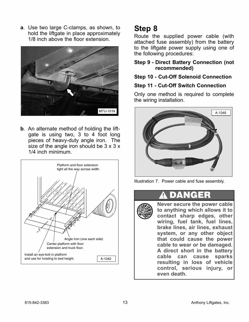
b. Raise the platform and position the lift-gate bolster (front edge of platform)tight against the floor extension.
c. Center the platform from side-to-sidewith the truck body.
Step 7Clamp the liftgate to the floor extension.
Anthony Liftgates, Inc. 12 815-842-3383
Do not remove the hoist, forklift, or other lifting deviceused to hold the liftgate inplace during the installationprocedure. NEVER WORKUNDER THE LIFTGATE ORFLOOR EXTENSION whileinstalling or painting the unit.Work so that you would not bein the way if the clamps, weld,etc. should fail.
WARNING
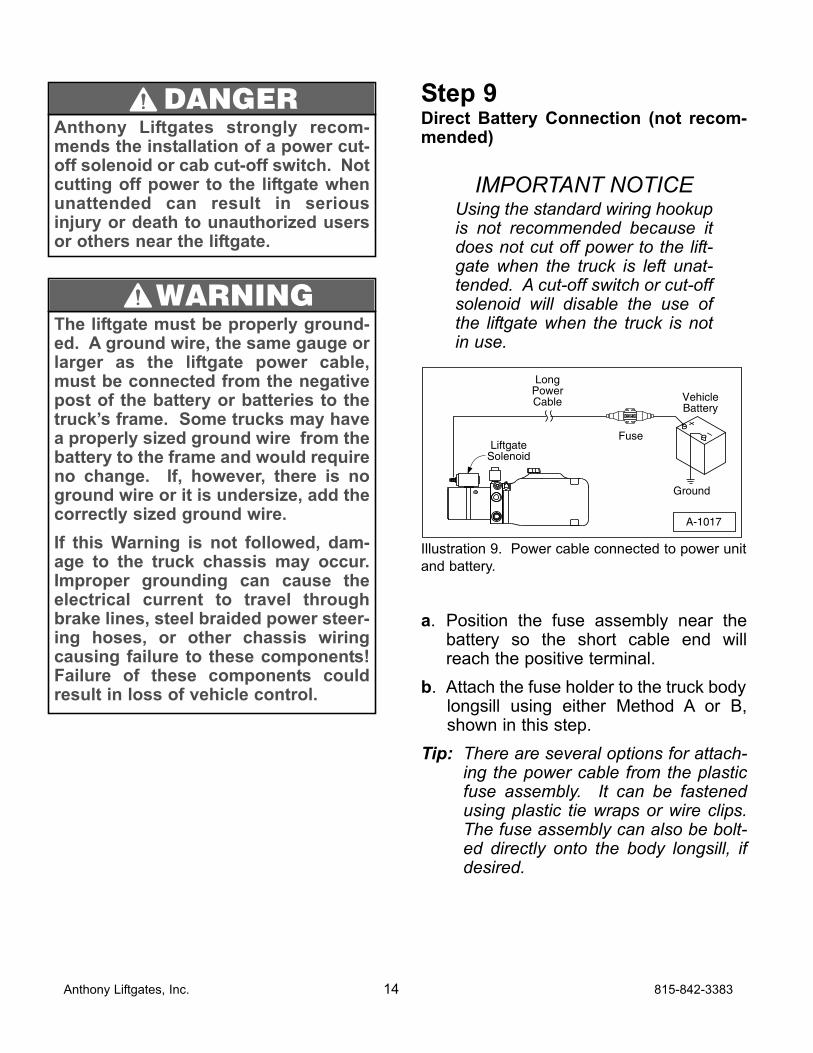
a. Use two large C-clamps, as shown, tohold the liftgate in place approximately1/8 inch above the floor extension.
b. An alternate method of holding the lift-gate is using two, 3 to 4 foot longpieces of heavy-duty angle iron. Thesize of the angle iron should be 3 x 3 x1/4 inch minimum.
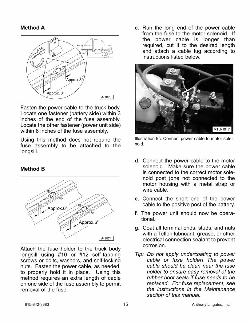
Step 8Route the supplied power cable (withattached fuse assembly) from the batteryto the liftgate power supply using one ofthe following procedures:
Step 9 - Direct Battery Connection (notrecommended)
Step 10 - Cut-Off Solenoid Connection
Step 11 - Cut-Off Switch Connection
Only one method is required to completethe wiring installation.
Illustration 7. Power cable and fuse assembly.
CL
A-1042
Platform and floor extensiontight all the way across width.
Angle Iron (one each side)
Center platform with floorextension and truck floor.
Install an eye-bolt in platformand use for hoisting to bed height.
815-842-3383 13 Anthony Liftgates, Inc.
Never secure the power cableto anything which allows it tocontact sharp edges, otherwiring, fuel tank, fuel lines,brake lines, air lines, exhaustsystem, or any other objectthat could cause the powercable to wear or be damaged.A direct short in the batterycable can cause sparksresulting in loss of vehiclecontrol, serious injury, oreven death.
DANGER
Step 9Direct Battery Connection (not recom-mended)
IMPORTANT NOTICEUsing the standard wiring hookupis not recommended because itdoes not cut off power to the lift-gate when the truck is left unat-tended. A cut-off switch or cut-offsolenoid will disable the use ofthe liftgate when the truck is notin use.
Illustration 9. Power cable connected to power unit
and battery.
a. Position the fuse assembly near thebattery so the short cable end willreach the positive terminal.
b. Attach the fuse holder to the truck bodylongsill using either Method A or B,shown in this step.
Tip: There are several options for attach-ing the power cable from the plasticfuse assembly. It can be fastenedusing plastic tie wraps or wire clips.The fuse assembly can also be bolt-ed directly onto the body longsill, ifdesired.
+–
LongPowerCable
Fuse
Ground
VehicleBattery
A-1017
LiftgateSolenoid
Anthony Liftgates, Inc. 14 815-842-3383
Anthony Liftgates strongly recom-mends the installation of a power cut-off solenoid or cab cut-off switch. Notcutting off power to the liftgate whenunattended can result in seriousinjury or death to unauthorized usersor others near the liftgate.
DANGER
The liftgate must be properly ground-ed. A ground wire, the same gauge orlarger as the liftgate power cable,must be connected from the negativepost of the battery or batteries to thetruck’s frame. Some trucks may havea properly sized ground wire from thebattery to the frame and would requireno change. If, however, there is noground wire or it is undersize, add thecorrectly sized ground wire.
If this Warning is not followed, dam-age to the truck chassis may occur.Improper grounding can cause theelectrical current to travel throughbrake lines, steel braided power steer-ing hoses, or other chassis wiringcausing failure to these components!Failure of these components couldresult in loss of vehicle control.
WARNING
Method A
Fasten the power cable to the truck body.Locate one fastener (battery side) within 3inches of the end of the fuse assembly.Locate the other fastener (power unit side)within 8 inches of the fuse assembly.
Using this method does not require thefuse assembly to be attached to thelongsill.
Method B
Attach the fuse holder to the truck bodylongsill using #10 or #12 self-tappingscrews or bolts, washers, and self-lockingnuts. Fasten the power cable, as needed,to properly hold it in place. Using thismethod requires an extra length of cableon one side of the fuse assembly to permitremoval of the fuse.
c. Run the long end of the power cablefrom the fuse to the motor solenoid. Ifthe power cable is longer thanrequired, cut it to the desired lengthand attach a cable lug according toinstructions listed below.
Illustration 9c. Connect power cable to motor sole-
noid.
d. Connect the power cable to the motorsolenoid. Make sure the power cableis connected to the correct motor sole-noid post (one not connected to themotor housing with a metal strap orwire cable.
e. Connect the short end of the powercable to the positive post of the battery.
f. The power unit should now be opera-tional.
g. Coat all terminal ends, studs, and nutswith a Teflon lubricant, grease, or otherelectrical connection sealant to preventcorrosion.
Tip: Do not apply undercoating to powercable or fuse holder! The powercable should be clean near the fuseholder to ensure easy removal of therubber boot seals if fuse needs to bereplaced. For fuse replacement, seethe instructions in the Maintenancesection of this manual.
A-1074
Approx.6"
Approx.6"
A-1073
TO LIFTGATE
Approx. 8"
Approx.3"
815-842-3383 15 Anthony Liftgates, Inc.
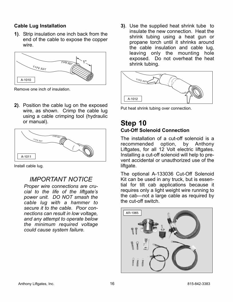
Cable Lug Installation
1). Strip insulation one inch back from theend of the cable to expose the copperwire.
Remove one inch of insulation.
2). Position the cable lug on the exposedwire, as shown. Crimp the cable lugusing a cable crimping tool (hydraulicor manual).
Install cable lug.
IMPORTANT NOTICEProper wire connections are cru-cial to the life of the liftgate’spower unit. DO NOT smash thecable lug with a hammer tosecure it to the cable. Poor con-nections can result in low voltage,and any attempt to operate belowthe minimum required voltagecould cause system failure.
3). Use the supplied heat shrink tube toinsulate the new connection. Heat theshrink tubing using a heat gun orpropane torch until it shrinks aroundthe cable insulation and cable lug,leaving only the mounting holeexposed. Do not overheat the heatshrink tubing.
Put heat shrink tubing over connection.
Step 10Cut-Off Solenoid Connection
The installation of a cut-off solenoid is arecommended option, by AnthonyLiftgates, for all 12 Volt electric liftgates.Installing a cut-off solenoid will help to pre-vent accidental or unauthorized use of theliftgate.
The optional A-133036 Cut-Off SolenoidKit can be used in any truck, but is essen-tial for tilt cab applications because itrequires only a light weight wire running tothe cab—not a large cable as required bythe cut-off switch.
A-1012
TYPE SGT
TYPE SGT
A-1011
TYPE SGT
TYPE SGT
TYPE SGT
TYPE SGT
A-1010
1"
Anthony Liftgates, Inc. 16 815-842-3383
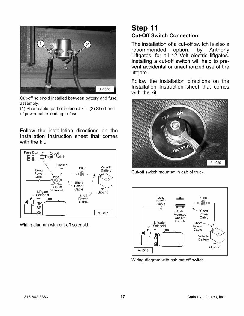
Cut-off solenoid installed between battery and fuse
assembly.
(1) Short cable, part of solenoid kit. (2) Short end
of power cable leading to fuse.
Follow the installation directions on theInstallation Instruction sheet that comeswith the kit.
Wiring diagram with cut-off solenoid.
Step 11Cut-Off Switch Connection
The installation of a cut-off switch is also arecommended option, by AnthonyLiftgates, for all 12 Volt electric liftgates.Installing a cut-off switch will help to pre-vent accidental or unauthorized use of theliftgate.
Follow the installation directions on theInstallation Instruction sheet that comeswith the kit.
Cut-off switch mounted in cab of truck.
Wiring diagram with cab cut-off switch.
A-1019
+–
LongPowerCable
Fuse
Ground
VehicleBattery
CabMountedCut-OffSwitch
ShortPowerCable
ShortPowerCable
LiftgateSolenoid
+–
Ground
A-1018
LongPowerCable
ShortPowerCable
ShortPower Cable
Fuse VehicleBattery
Ground
Cut-OffSolenoid
Fuse Box On/OffToggle Switch
LiftgateSolenoid
815-842-3383 17 Anthony Liftgates, Inc.
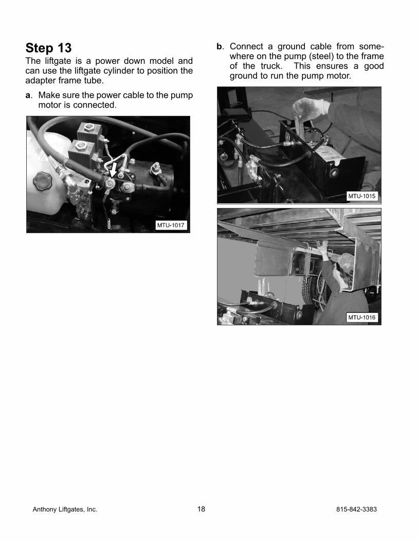
Step 13The liftgate is a power down model andcan use the liftgate cylinder to position theadapter frame tube.
a. Make sure the power cable to the pumpmotor is connected.
b. Connect a ground cable from some-where on the pump (steel) to the frameof the truck. This ensures a goodground to run the pump motor.
Anthony Liftgates, Inc. 18 815-842-3383
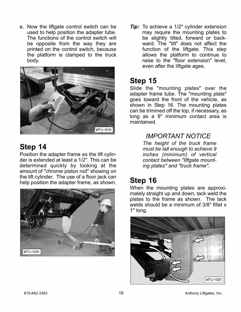
c. Now the liftgate control switch can beused to help position the adapter tube.The functions of the control switch willbe opposite from the way they areprinted on the control switch, becausethe platform is clamped to the truckbody.
Step 14Position the adapter frame so the lift cylin-der is extended at least a 1/2". This can bedetermined quickly by looking at theamount of "chrome piston rod" showing onthe lift cylinder. The use of a floor jack canhelp position the adapter frame, as shown.
Tip: To achieve a 1/2" cylinder extensionmay require the mounting plates tobe slightly tilted, forward or back-ward. The "tilt" does not affect thefunction of the liftgate. This stepallows the platform to continue toraise to the "floor extension" level,even after the liftgate ages.
Step 15Slide the "mounting plates" over theadapter frame tube. The "mounting plate"goes toward the front of the vehicle, asshown in Step 16. The mounting platescan be trimmed off the top, if necessary, aslong as a 9" minimum contact area ismaintained.
IMPORTANT NOTICEThe height of the truck framemust be tall enough to achieve 9inches (minimum) of verticalcontact between "liftgate mount-ing plates" and "truck frame".
Step 16When the mounting plates are approxi-mately straight up and down, tack weld theplates to the frame as shown. The tackwelds should be a minimum of 3/8" fillet x1" long.
815-842-3383 19 Anthony Liftgates, Inc.
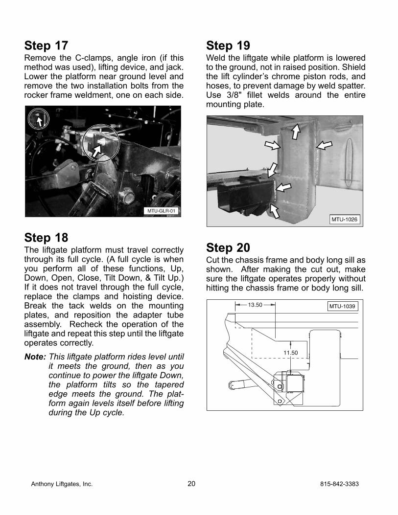
Step 17Remove the C-clamps, angle iron (if thismethod was used), lifting device, and jack.Lower the platform near ground level andremove the two installation bolts from therocker frame weldment, one on each side.
Step 18The liftgate platform must travel correctlythrough its full cycle. (A full cycle is whenyou perform all of these functions, Up,Down, Open, Close, Tilt Down, & Tilt Up.)If it does not travel through the full cycle,replace the clamps and hoisting device.Break the tack welds on the mountingplates, and reposition the adapter tubeassembly. Recheck the operation of theliftgate and repeat this step until the liftgateoperates correctly.
Note: This liftgate platform rides level untilit meets the ground, then as youcontinue to power the liftgate Down,the platform tilts so the taperededge meets the ground. The plat-form again levels itself before liftingduring the Up cycle.
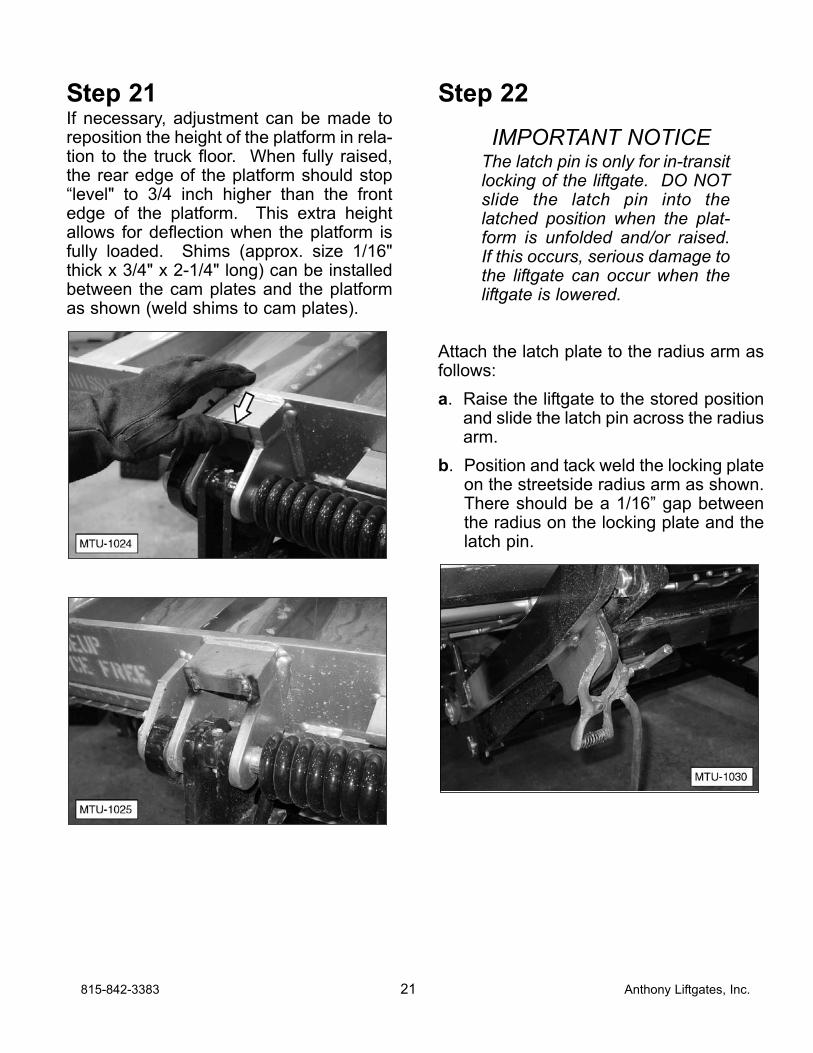
Step 19Weld the liftgate while platform is loweredto the ground, not in raised position. Shieldthe lift cylinder’s chrome piston rods, andhoses, to prevent damage by weld spatter.Use 3/8" fillet welds around the entiremounting plate.
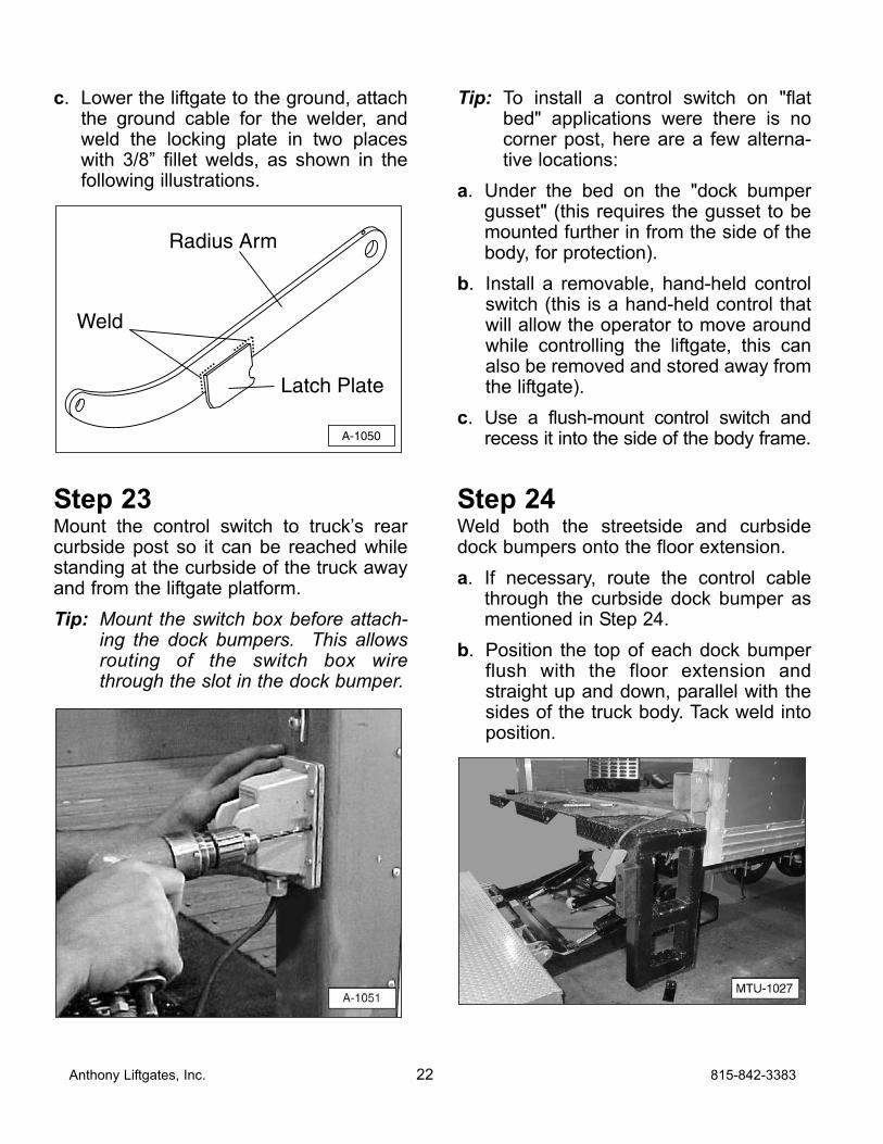
Step 20Cut the chassis frame and body long sill asshown. After making the cut out, makesure the liftgate operates properly withouthitting the chassis frame or body long sill.
MTU-103913.50
11.50
Anthony Liftgates, Inc. 20 815-842-3383
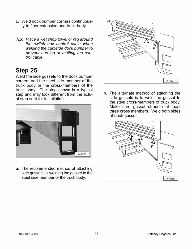
Step 21If necessary, adjustment can be made toreposition the height of the platform in rela-tion to the truck floor. When fully raised,the rear edge of the platform should stop“level" to 3/4 inch higher than the frontedge of the platform. This extra heightallows for deflection when the platform isfully loaded. Shims (approx. size 1/16"thick x 3/4" x 2-1/4" long) can be installedbetween the cam plates and the platformas shown (weld shims to cam plates).
Step 22
IMPORTANT NOTICEThe latch pin is only for in-transitlocking of the liftgate. DO NOTslide the latch pin into thelatched position when the plat-form is unfolded and/or raised.If this occurs, serious damage tothe liftgate can occur when theliftgate is lowered.
Attach the latch plate to the radius arm asfollows:
a. Raise the liftgate to the stored positionand slide the latch pin across the radiusarm.
b. Position and tack weld the locking plateon the streetside radius arm as shown.There should be a 1/16” gap betweenthe radius on the locking plate and thelatch pin.
815-842-3383 21 Anthony Liftgates, Inc.
c. Lower the liftgate to the ground, attachthe ground cable for the welder, andweld the locking plate in two placeswith 3/8” fillet welds, as shown in thefollowing illustrations.
Step 23Mount the control switch to truck’s rearcurbside post so it can be reached whilestanding at the curbside of the truck awayand from the liftgate platform.
Tip: Mount the switch box before attach-ing the dock bumpers. This allowsrouting of the switch box wirethrough the slot in the dock bumper.
Tip: To install a control switch on "flatbed" applications were there is nocorner post, here are a few alterna-tive locations:
a. Under the bed on the "dock bumpergusset" (this requires the gusset to bemounted further in from the side of thebody, for protection).
b. Install a removable, hand-held controlswitch (this is a hand-held control thatwill allow the operator to move aroundwhile controlling the liftgate, this canalso be removed and stored away fromthe liftgate).
c. Use a flush-mount control switch andrecess it into the side of the body frame.
Step 24Weld both the streetside and curbsidedock bumpers onto the floor extension.
a. If necessary, route the control cablethrough the curbside dock bumper asmentioned in Step 24.
b. Position the top of each dock bumperflush with the floor extension andstraight up and down, parallel with thesides of the truck body. Tack weld intoposition.
A-1050
Weld
Radius Arm
Latch Plate
Anthony Liftgates, Inc. 22 815-842-3383
c. Weld dock bumper corners continuous-ly to floor extension and truck body.
Tip: Place a wet shop towel or rag aroundthe switch box control cable whenwelding the curbside dock bumper toprevent burning or melting the con-trol cable.
Step 25Weld the side gussets to the dock bumpercorners and the steel side member of thetruck body or the cross-members of thetruck body. The step shown is a typicalstep and may look different from the actu-al step sent for installation.
a. The recommended method of attachingside gussets, is welding the gusset to thesteel side member of the truck body.
b. The alternate method of attaching theside gussets is to weld the gusset tothe steel cross-members of truck body.Make sure gusset straddle at leastthree cross members. Weld both sidesof each gusset.
A-1038
A-1037
815-842-3383 23 Anthony Liftgates, Inc.
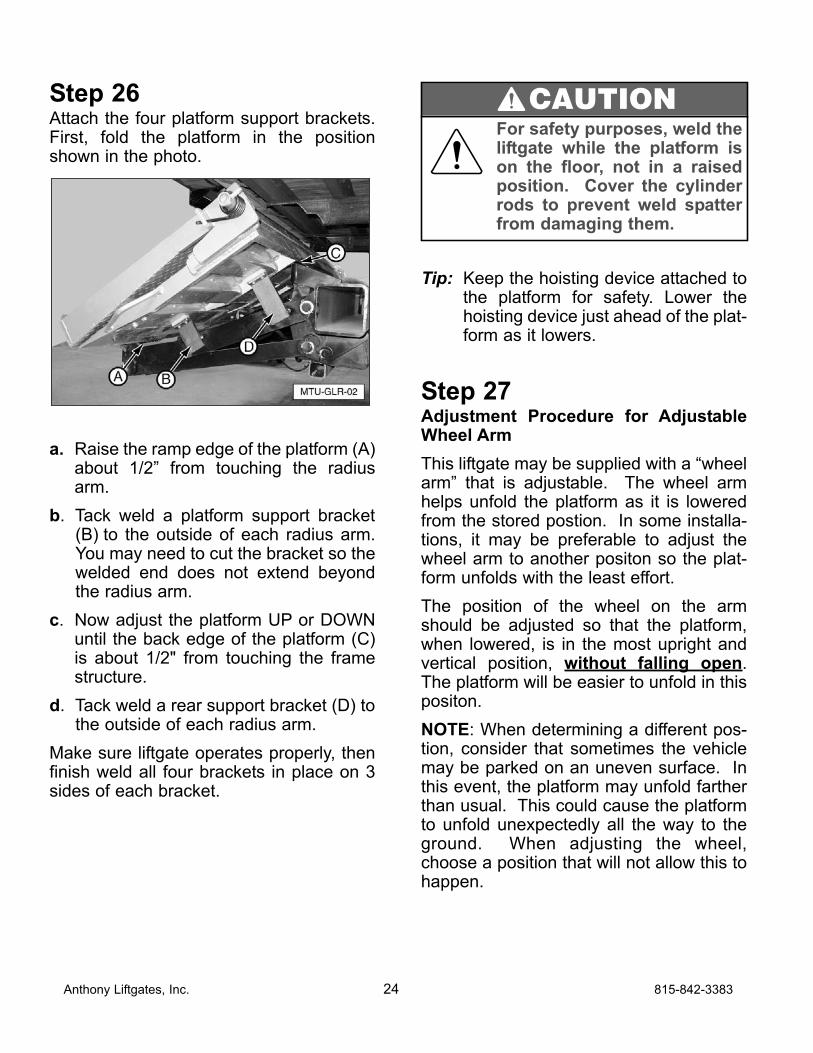
Step 26Attach the four platform support brackets.First, fold the platform in the positionshown in the photo.
a. Raise the ramp edge of the platform (A)about 1/2” from touching the radiusarm.
b. Tack weld a platform support bracket(B) to the outside of each radius arm.You may need to cut the bracket so thewelded end does not extend beyondthe radius arm.
c. Now adjust the platform UP or DOWNuntil the back edge of the platform (C)is about 1/2" from touching the framestructure.
d. Tack weld a rear support bracket (D) tothe outside of each radius arm.
Make sure liftgate operates properly, thenfinish weld all four brackets in place on 3sides of each bracket.
Tip: Keep the hoisting device attached tothe platform for safety. Lower thehoisting device just ahead of the plat-form as it lowers.
Step 27Adjustment Procedure for AdjustableWheel Arm
This liftgate may be supplied with a “wheelarm” that is adjustable. The wheel armhelps unfold the platform as it is loweredfrom the stored postion. In some installa-tions, it may be preferable to adjust thewheel arm to another positon so the plat-form unfolds with the least effort.
The position of the wheel on the armshould be adjusted so that the platform,when lowered, is in the most upright andvertical position, without falling open.The platform will be easier to unfold in thispositon.
NOTE: When determining a different pos-tion, consider that sometimes the vehiclemay be parked on an uneven surface. Inthis event, the platform may unfold fartherthan usual. This could cause the platformto unfold unexpectedly all the way to theground. When adjusting the wheel,choose a position that will not allow this tohappen.
Anthony Liftgates, Inc. 24 815-842-3383
For safety purposes, weld theliftgate while the platform ison the floor, not in a raisedposition. Cover the cylinderrods to prevent weld spatterfrom damaging them.
CAUTION
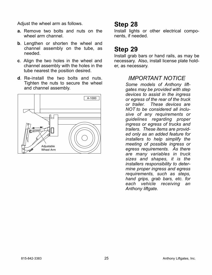
Adjust the wheel arm as follows.
a. Remove two bolts and nuts on thewheel arm channel.
b. Lengthen or shorten the wheel andchannel assembly on the tube, asneeded.
c. Align the two holes in the wheel andchannel assembly with the holes in thetube nearest the position desired.
d. Re-install the two bolts and nuts.Tighten the nuts to secure the wheeland channel assembly.
Step 28Install lights or other electrical compo-nents, if needed.
Step 29Install grab bars or hand rails, as may benecessary. Also, install license plate hold-er, as necessary.
IMPORTANT NOTICESome models of Anthony lift-gates may be provided with stepdevices to assist in the ingressor egress of the rear of the truckor trailer. These devices areNOT to be considered all inclu-sive of any requirements orguidelines regarding properingress or egress of trucks andtrailers. These items are provid-ed only as an added feature forinstallers to help simplify themeeting of possible ingress oregress requirements. As thereare many variables in trucksizes and shapes, it is theinstallers responsibility to deter-mine proper ingress and egressrequirements, such as steps,hand grips, grab bars, etc. foreach vehicle receiving anAnthony liftgate.
A-1000
AdjustableWheel Arm
815-842-3383 25 Anthony Liftgates, Inc.
Step 30Make a final operation check. Rememberthat this liftgate is a power down model,therefore the pump will run while the plat-form is lowering.
a. Make sure the platform will travelthrough a complete cycle, up anddown, smoothly and freely, with theplatform completely open.
b. Make sure the platform will fold andtuck under the truck in a stored posi-tion, and latch. The liftgate must foldsmoothly and freely.
c. Make sure hydraulic hose fittings aretight and hydraulic hose does not rubagainst the liftgate or other parts whilecycling up, down, open, and closed.Adjust as necessary by loosening fittingsand adjusting the position of the hose(s).Retighten fittings.
Step 31Attach all decals, as shown in the Decalsection of this manual.
Step 32Complete the Final Checklist section.
Anthony Liftgates, Inc. 26 815-842-3383
❏ Check all welds to make sure they aredone properly.
❏ Make sure all pins are in place and heldwith proper retainers.
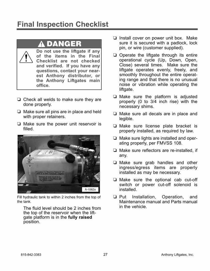
❏ Make sure the power unit reservoir isfilled.
Fill hydraulic tank to within 2 inches from the top of
the tank.
The fluid level should be 2 inches fromthe top of the reservoir when the lift-gate platform is in the fully raisedposition.
❏ Install cover on power unit box. Makesure it is secured with a padlock, lockpin, or wire (customer supplied).
❏ Operate the liftgate through its entireoperational cycle (Up, Down, Open,Close) several times. Make sure theliftgate operates evenly, freely, andsmoothly throughout the entire operat-ing range and that there is no unusualnoise or vibration while operating theliftgate.
❏ Make sure the platform is adjustedproperly (0 to 3/4 inch rise) with thenecessary shims.
❏ Make sure all decals are in place andlegible.
❏ Make sure license plate bracket isproperly installed, as required by law.
❏ Make sure lights are installed and oper-ating properly, per FMVSS 108.
❏ Make sure reflectors are re-installed, ifany.
❏ Make sure grab handles and otheringress/egress items are properlyinstalled as may be necessary.
❏ Make sure the optional cab cut-offswitch or power cut-off solenoid isinstalled.
❏ Put Installation, Operation, andMaintenance manual and Parts manualin the vehicle.
815-842-3383 27 Anthony Liftgates, Inc.
Final Inspection Checklist
Do not use the liftgate if anyof the items in the FinalChecklist are not checkedand verified. If you have anyquestions, contact your near-est Anthony distributor, orthe Anthony Liftgates mainoffice.
DANGER
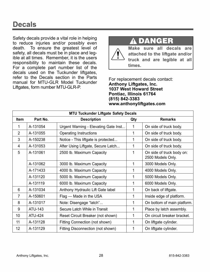
Safety decals provide a vital role in helpingto reduce injuries and/or possibly evendeath. To ensure the greatest level ofsafety, all decals must be in place and leg-ible at all times. Remember, it is the usersresponsibility to maintain these decals.For a complete part number list of thedecals used on the Tuckunder liftgates,refer to the Decals section in the Partsmanual for MTU-GLR Model TuckunderLiftgates, form number MTU-GLR-P.
For replacement decals contact:Anthony Liftgates, Inc.1037 West Howard StreetPontiac, Illinois 61764(815) 842-3383www.anthonyliftgates.com
Anthony Liftgates, Inc. 28 815-842-3383
Decals
Make sure all decals are
attached to the liftgate and/or
truck and are legible at all
times.
DANGER
MTU Tuckunder Liftgate Safety Decals
Item Part No. Description Qty Remarks
1 A-131054 Urgent Warning - Elevating Gate Inst... 1 On side of truck body.
2 A-131055 Operating Instructions 1 On side of truck body.
3 A-150238 Notice - This liftgate is protected... 1 On side of truck body.
4 A-131053 After Using Liftgate, Secure Latch... 1 On side of truck body.
5 A-131061 2500 lb. Maximum Capacity 1 On side of truck body on:
2500 Models Only.
A-131062 3000 lb. Maximum Capacity 1 3000 Models Only.
A-171433 4000 lb. Maximum Capacity 1 4000 Models Only.
A-131120 5000 lb. Maximum Capacity 1 5000 Models Only.
A-131119 6000 lb. Maximum Capacity 1 6000 Models Only.
6 A-131034 Anthony Hydraulic Lift Gate label 1 On back of liftgate.
7 A-150601 Flag — Made in the USA 1 Inside edge of platform.
8 A-131017 Note: Disengage “latch”... 1 On bottom of main platform.
9 ATU-143 Secure Latch While in Transit 1 Place by latch assembly.
10 ATU-424 Reset Circuit Breaker (not shown) 1 On circuit breaker bracket.
11 A-131128 Fitting Connection (not shown) 1 On liftgate cylinder.
12 A-131129 Fitting Disconnection (not shown) 1 On liftgate cylinder.
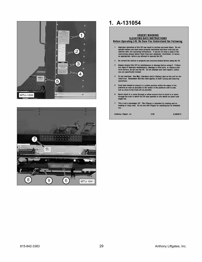
1. A-131054
815-842-3383 29 Anthony Liftgates, Inc.
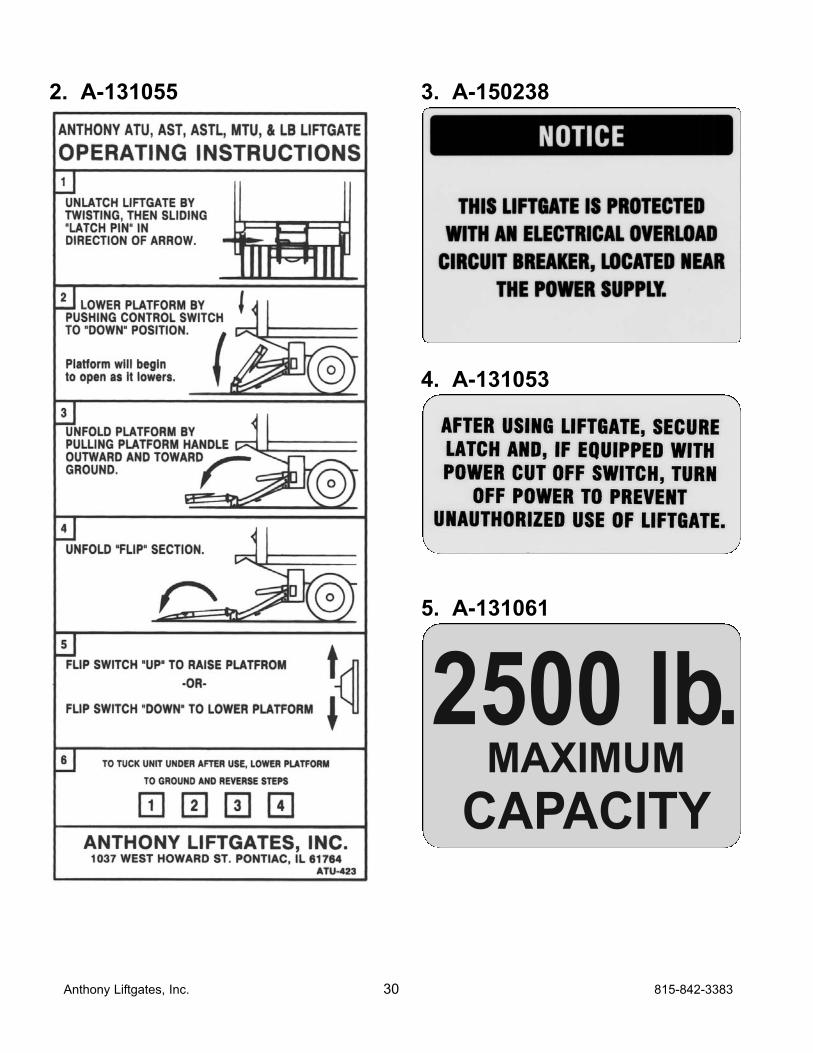
2. A-131055 3. A-150238
4. A-131053
5. A-131061
MAXIMUMCAPACITY
2500 lb.
Anthony Liftgates, Inc. 30 815-842-3383
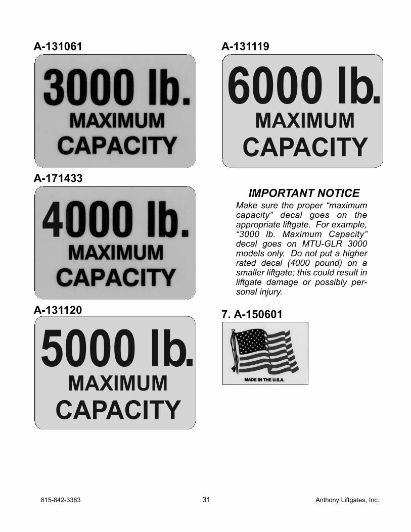
A-131061
A-171433
A-131120
A-131119
IMPORTANT NOTICEMake sure the proper “maximumcapacity” decal goes on theappropriate liftgate. For example,“3000 lb. Maximum Capacity”decal goes on MTU-GLR 3000models only. Do not put a higherrated decal (4000 pound) on asmaller liftgate; this could result inliftgate damage or possibly per-sonal injury.
7. A-150601
MAXIMUMCAPACITY
6000 lb.
MAXIMUMCAPACITY
5000 lb.
815-842-3383 31 Anthony Liftgates, Inc.
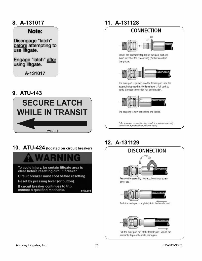
8. A-131017
9. ATU-143
10. ATU-424 (located on circuit breaker)
11. A-131128
12. A-131129
ATU-143
SECURE LATCH WHILE IN TRANSIT
Anthony Liftgates, Inc. 32 815-842-3383
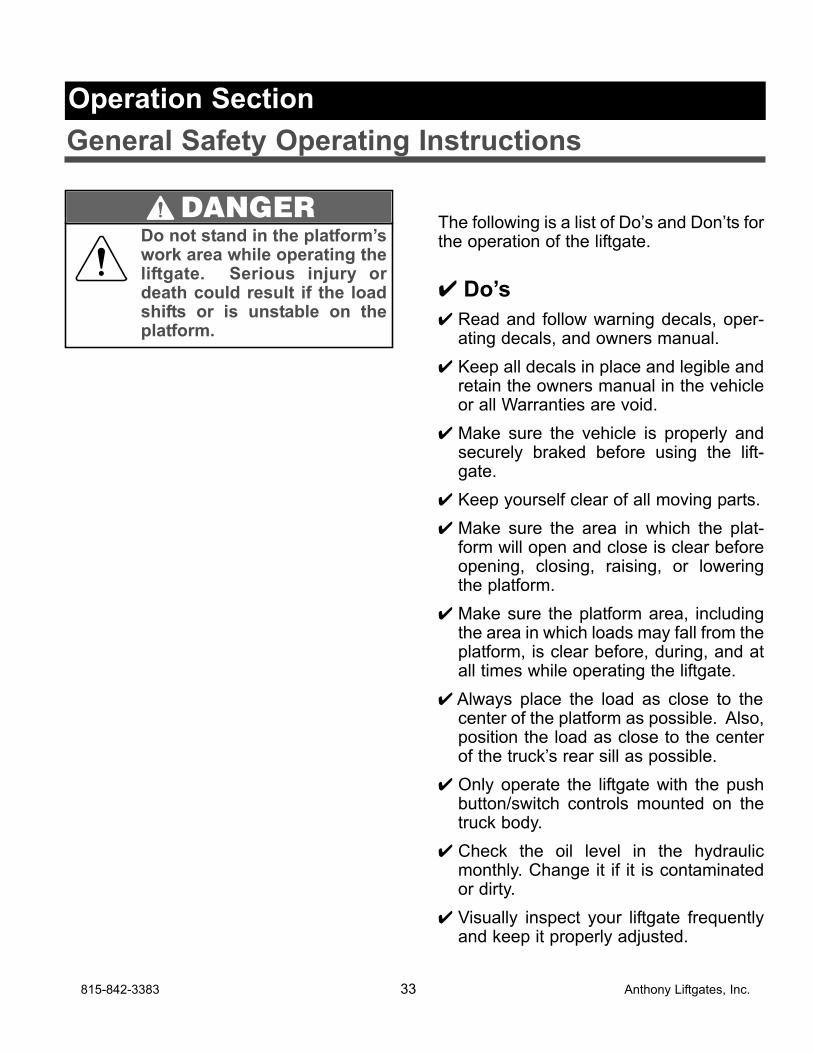
The following is a list of Do’s and Don’ts forthe operation of the liftgate.
✔ Do’s
✔ Read and follow warning decals, oper-ating decals, and owners manual.
✔ Keep all decals in place and legible andretain the owners manual in the vehicleor all Warranties are void.
✔ Make sure the vehicle is properly andsecurely braked before using the lift-gate.
✔ Keep yourself clear of all moving parts.
✔ Make sure the area in which the plat-form will open and close is clear beforeopening, closing, raising, or loweringthe platform.
✔ Make sure the platform area, includingthe area in which loads may fall from theplatform, is clear before, during, and atall times while operating the liftgate.
✔ Always place the load as close to thecenter of the platform as possible. Also,position the load as close to the centerof the truck’s rear sill as possible.
✔ Only operate the liftgate with the pushbutton/switch controls mounted on thetruck body.
✔ Check the oil level in the hydraulicmonthly. Change it if it is contaminatedor dirty.
✔ Visually inspect your liftgate frequentlyand keep it properly adjusted.
815-842-3383 33 Anthony Liftgates, Inc.
General Safety Operating Instructions
Operation Section
Do not stand in the platform’swork area while operating theliftgate. Serious injury ordeath could result if the loadshifts or is unstable on theplatform.
DANGER
✔ Repair any damage to the liftgate to pre-vent accidents.
✔ Lock the liftgate into the storage posi-tion with the latch pin when the liftgate isnot in use.
✘ Don’ts
✘ Do not overload the platform. The maxi-mum rated capacity is based on anevenly distributed load on the platform’sflat surface.
✘ Do not ride on the liftgate. Always standclear of liftgate when it is operating.
✘ Do not allow children to play around oroperate the liftgate.
✘ Do not allow your liftgate to be used bypersons not familiar with its operation.
✘ Do not use your liftgate if it shows signsof abuse or fails to operate freely.
✘ Do not allow the motor/pump to run afterthe liftgate is closed, or in the up posi-tion.
✘ Do not use brake fluid in the hydraulicreservoir.
✘ Do not bounce the platform by pushingand releasing the control button/switchabruptly.
✘ Do not use the liftgate for anything otherthan its intended use of loading andunloading cargo.
✘ Do not operate lift trucks on or over anypart of the platform.
✘ Do not stand under or place any objectunder the liftgate work area.
Anthony Liftgates, Inc. 34 815-842-3383
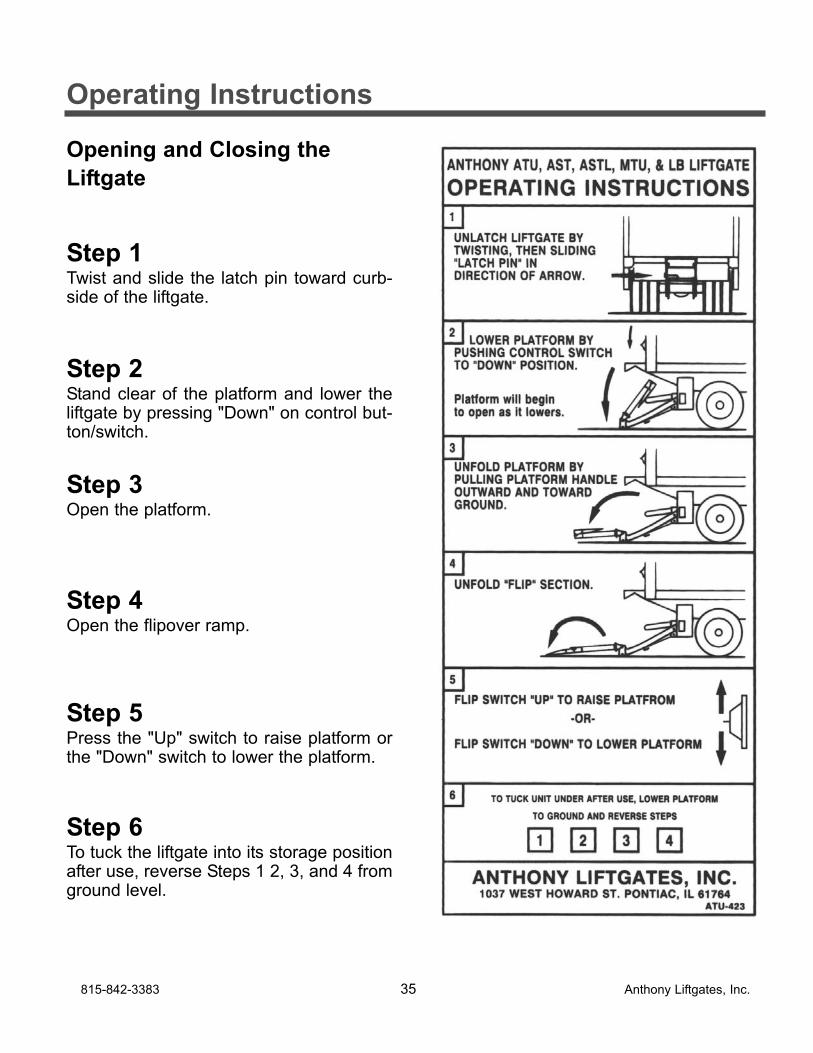
Opening and Closing the
Liftgate
Step 1Twist and slide the latch pin toward curb-side of the liftgate.
Step 2Stand clear of the platform and lower theliftgate by pressing "Down" on control but-ton/switch.
Step 3Open the platform.
Step 4Open the flipover ramp.
Step 5Press the "Up" switch to raise platform orthe "Down" switch to lower the platform.
Step 6To tuck the liftgate into its storage positionafter use, reverse Steps 1 2, 3, and 4 fromground level.
815-842-3383 35 Anthony Liftgates, Inc.
Operating Instructions
Monthly Inspection
SPECIAL NOTE: As of December 1994Anthony Tuckunder Liftgates are “Service-Free”. This means that newer liftgateshave lubrication-free bushings at the majorpivot points which, of course, do notrequire lubrication. Consequently theseliftgates do not have grease zerks.
1. Make sure the liftgate operates freelyand smoothly throughout its entirerange of movement.
2. Check for damage to the liftgate suchas bent or distorted members, or anycracked weld which may have resultedfrom overload or abuse. Check forexcessively worn parts. Replace bush-ings and pins if extremely worn.
3. Check all pins and pivot points. Makesure they are secured with properretainers.
4. Make sure platform is angled upwardfrom truck bed 0 to 3/4 inch whenraised to bed height. See PlatformAdjustment for a shimming procedure.
5. Make sure all electrical wires, switches,and connections are in good workingcondition and operate properly.
6. Check for oil leaks in these areas:
a. Hydraulic lift cylinder.
b. Hydraulic hoses. Replace if theyshow signs of leakage or excessiveabrasion of the covering.
c. Check all hydraulic fittings fordamage or leaks. Tighten fittingsto stop leaks or replace if dam-aged.
7. Check reservoir oil level.
a. Place liftgate in the fully raised, theoil level should be within 1/2 inchof the top of the reservoir.
b. Fill as required with Penzoil AWXAutomatic Transmission Fluid orequivalent.
IMPORTANT NOTICEUse only Penzoil AWXAutomatic Transmission Fluid orequivalent in the power unitreservoir. Do not use brakefluid.
8. Check the fluid level of the vehicle bat-tery. Fill as required.
9. Examine all Warning, Capacity, andOperational Decals. If they are notreadable they should be replaced.Decals may be obtained from AnthonyLiftgates, Inc.
10. Oil the roller wheel and make sure itspins freely.
Anthony Liftgates, Inc. 36 815-842-3383
Quick Check Maintenance Guide
Maintenance Section
Checking Battery Cable
To check for a bad battery cable, run themotor directly from a spare battery usingjumper cables.
1. Remove the battery connection to themotor.
2. Connect the negative jumper cable(ground) directly to the liftgate.Connect the positive cable to the termi-nal on the motor start solenoid.
3. Depress the switch, if the motor oper-ates, the battery cable is bad andshould be replaced.
Replacing the Fuse
To replace a fuse:
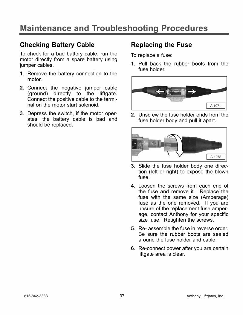
1. Pull back the rubber boots from thefuse holder.
2. Unscrew the fuse holder ends from thefuse holder body and pull it apart.
3. Slide the fuse holder body one direc-tion (left or right) to expose the blownfuse.
4. Loosen the screws from each end ofthe fuse and remove it. Replace thefuse with the same size (Amperage)fuse as the one removed. If you areunsure of the replacement fuse amper-age, contact Anthony for your specificsize fuse. Retighten the screws.
5. Re- assemble the fuse in reverse order.Be sure the rubber boots are sealedaround the fuse holder and cable.
6. Re-connect power after you are certainliftgate area is clear.
815-842-3383 37 Anthony Liftgates, Inc.
Maintenance and Troubleshooting Procedures
Checking Motor Start Solenoidand Power Cut-off Solenoid
Both the motor start solenoid and powercut-off solenoid can be checked bybypassing the solenoid itself.
1. Use jumper cables for this test.
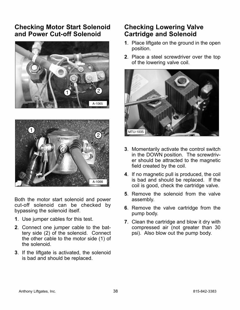
2. Connect one jumper cable to the bat-tery side (2) of the solenoid. Connectthe other cable to the motor side (1) ofthe solenoid.
3. If the liftgate is activated, the solenoidis bad and should be replaced.
Checking Lowering ValveCartridge and Solenoid
1. Place liftgate on the ground in the openposition.
2. Place a steel screwdriver over the topof the lowering valve coil.
3. Momentarily activate the control switchin the DOWN position. The screwdriv-er should be attracted to the magneticfield created by the coil.
4. If no magnetic pull is produced, the coilis bad and should be replaced. If thecoil is good, check the cartridge valve.
5. Remove the solenoid from the valveassembly.
6. Remove the valve cartridge from thepump body.
7. Clean the cartridge and blow it dry withcompressed air (not greater than 30psi). Also blow out the pump body.
Anthony Liftgates, Inc. 38 815-842-3383
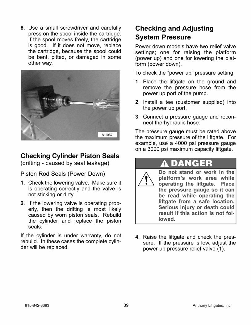
8. Use a small screwdriver and carefullypress on the spool inside the cartridge.If the spool moves freely, the cartridgeis good. If it does not move, replacethe cartridge, because the spool couldbe bent, pitted, or damaged in someother way.
Checking Cylinder Piston Seals(drifting - caused by seal leakage)
Piston Rod Seals (Power Down)
1. Check the lowering valve. Make sure itis operating correctly and the valve isnot sticking or dirty.
2. If the lowering valve is operating prop-erly, then the drifting is most likelycaused by worn piston seals. Rebuildthe cylinder and replace the pistonseals.
If the cylinder is under warranty, do notrebuild. In these cases the complete cylin-der will be replaced.
Checking and Adjusting
System Pressure
Power down models have two relief valvesettings; one for raising the platform(power up) and one for lowering the plat-form (power down).
To check the “power up” pressure setting:
1. Place the liftgate on the ground andremove the pressure hose from thepower up port of the pump.
2. Install a tee (customer supplied) intothe power up port.
3. Connect a pressure gauge and recon-nect the hydraulic hose.
The pressure gauge must be rated abovethe maximum pressure of the liftgate. Forexample, use a 4000 psi pressure gaugeon a 3000 psi maximum capacity liftgate.
4. Raise the liftgate and check the pres-sure. If the pressure is low, adjust thepower-up pressure relief valve (1).
815-842-3383 39 Anthony Liftgates, Inc.
Do not stand or work in theplatform’s work area whileoperating the liftgate. Placethe pressure gauge so it canbe read while operating theliftgate from a safe location.Serious injury or death couldresult if this action is not fol-lowed.
DANGER
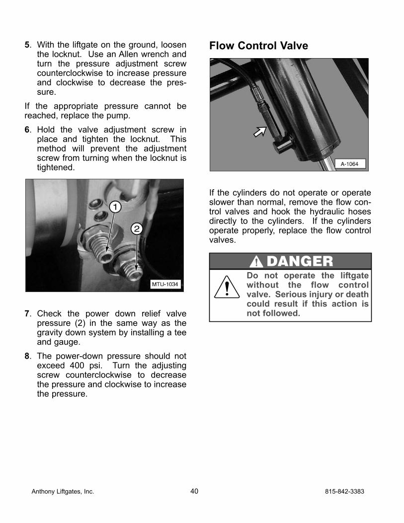
5. With the liftgate on the ground, loosenthe locknut. Use an Allen wrench andturn the pressure adjustment screwcounterclockwise to increase pressureand clockwise to decrease the pres-sure.
If the appropriate pressure cannot bereached, replace the pump.
6. Hold the valve adjustment screw inplace and tighten the locknut. Thismethod will prevent the adjustmentscrew from turning when the locknut istightened.
7. Check the power down relief valvepressure (2) in the same way as thegravity down system by installing a teeand gauge.
8. The power-down pressure should notexceed 400 psi. Turn the adjustingscrew counterclockwise to decreasethe pressure and clockwise to increasethe pressure.
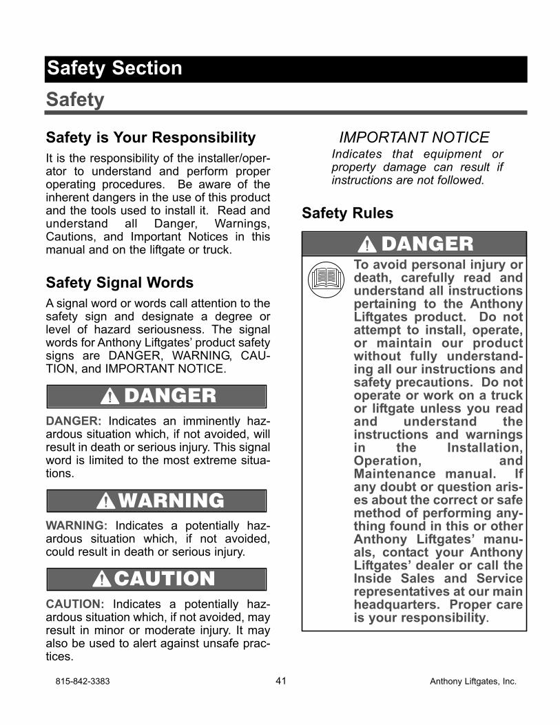
Flow Control Valve
If the cylinders do not operate or operateslower than normal, remove the flow con-trol valves and hook the hydraulic hosesdirectly to the cylinders. If the cylindersoperate properly, replace the flow controlvalves.
Anthony Liftgates, Inc. 40 815-842-3383
Do not operate the liftgatewithout the flow controlvalve. Serious injury or deathcould result if this action isnot followed.
DANGER
Safety is Your Responsibility
It is the responsibility of the installer/oper-ator to understand and perform properoperating procedures. Be aware of theinherent dangers in the use of this productand the tools used to install it. Read andunderstand all Danger, Warnings,Cautions, and Important Notices in thismanual and on the liftgate or truck.
Safety Signal Words
A signal word or words call attention to thesafety sign and designate a degree orlevel of hazard seriousness. The signalwords for Anthony Liftgates’ product safetysigns are DANGER, WARNING, CAU-TION, and IMPORTANT NOTICE.
DANGER: Indicates an imminently haz-ardous situation which, if not avoided, willresult in death or serious injury. This signalword is limited to the most extreme situa-tions.
WARNING: Indicates a potentially haz-ardous situation which, if not avoided,could result in death or serious injury.
CAUTION: Indicates a potentially haz-ardous situation which, if not avoided, mayresult in minor or moderate injury. It mayalso be used to alert against unsafe prac-tices.
IMPORTANT NOTICEIndicates that equipment orproperty damage can result ifinstructions are not followed.
Safety Rules
CAUTION
WARNING
DANGER
815-842-3383 41 Anthony Liftgates, Inc.
To avoid personal injury ordeath, carefully read andunderstand all instructionspertaining to the AnthonyLiftgates product. Do notattempt to install, operate,or maintain our productwithout fully understand-ing all our instructions andsafety precautions. Do notoperate or work on a truckor liftgate unless you readand understand theinstructions and warningsin the Installation,Operation, andMaintenance manual. Ifany doubt or question aris-es about the correct or safemethod of performing any-thing found in this or otherAnthony Liftgates’ manu-als, contact your AnthonyLiftgates’ dealer or call theInside Sales and Servicerepresentatives at our mainheadquarters. Proper careis your responsibility.
DANGER
Safety Section
Safety
Anthony Liftgates, Inc. 42 815-842-3383
To prevent injury, make sureall decals are attached to theliftgate and/or truck and arelegible at all times.
DANGERTo prevent injury, the liftgateshould only be installed by aqualified installer havingknowledge and skill in usingwelding equipment and a cut-ting torch.
Always weld in a well ventilat-ed area and, if in an enclosedarea, vent the fumes to theoutside. Breathing weldingsmoke and paint fumes cancause serious injury.
Always follow all State andFederal health and safety lawsand/or local regulations whenusing an arc welder, migwelder, or cutting torch. Also,follow all manufacturer’s safetyguidelines. If other people arepresent during the installationof the liftgate, make sure thewelding area is shield fromtheir view. This will help pre-vent serious eye injury from thebright light.
To avoid eye injury duringwelding, always wear a weld-ing helmet with the properlens to shield your eyes fromthe bright light.
Failure to prevent the truckfrom moving during theinstallation of the liftgatecould result in serious per-sonal injury or crushing ofthe installer(s).
DANGER
To prevent serious bodily injury, keepsparks, lighted matches, and openflames away from the top of the bat-tery, because battery gas can explode.Always follow all the manufacturers’safety recommendations when work-ing around the truck’s battery.
Take precautions to avoidsparks coming into contactwith the truck’s fuel tank,brake lines, or other flamma-ble components. Sparks cancause an explosion of com-bustible materials, resultingin serious injury or death.
Never secure the power cableto anything which allows it tocontact sharp edges, otherwiring, fuel tank, fuel lines,brake lines, air lines, exhaustsystem, or any other objectthat could cause the powercable to wear or be damaged.A cut battery cable can causesparks resulting in loss ofvehicle control, seriousinjury, or even death.
DANGER
815-842-3383 43 Anthony Liftgates, Inc.
Most accidents involving theoperation, maintenance, or repairof products made by AnthonyLiftgates occur because theinstaller/owner/operator failed toobserve basic safety rules oroperating instructions. Accidentscan often be avoided by beingalert and recognizing potentiallyhazardous situations. Any indi-viduals installing, operating,maintaining, or repairing productsmanufactured by AnthonyLiftgates should have the neces-sary training, skills, and toolsrequired to perform these func-tions properly and safely. Thesafety information in this manualserves as a basic guide in anattempt to prevent injury or death.
Anthony Liftgates cannot antici-pate every possible circum-stance that might involve apotential hazard. The warningsin this manual and on the prod-uct itself are, therefore, not allinclusive. If tools, procedures,work methods, or operatingtechniques that are not specifi-cally mentioned by AnthonyLiftgates are used, you must sat-isfy yourself that they are safefor you and for others. Makesure the liftgate or truck it ismounted onto will not be dam-aged or made unsafe by anyoperation, lubrication, mainte-nance, or repair procedures thatyou choose.
DO NOT proceed, if any doubtarises about the correct or safemethod of performing anythingfound in this or other AnthonyLiftgates’ manuals. Seek outexpert assistance from a quali-fied person before continuing.
WARNINGUse extreme caution if work-ing under the liftgate duringinstallation. Failure to safelysecure the liftgate to the floorextension could cause seri-ous personal injury. Do notremove the lifting device(s)until the liftgate is completelywelded onto the truck.
To prevent personal injury,clean up any spilled fluidsimmediately. To avoid trip-ping, do not leave tools orcomponents laying around inthe work area.
Do not place hands or feet inpinch points.
Do not ride on the platform.
Do not place your feet underthe liftgate.
Always use/set the truck’sparking brake before operat-ing the liftgate. Failure to fol-low this recommendation canresult in injury.
WARNING
Anthony Liftgates, Inc. 44 815-842-3383
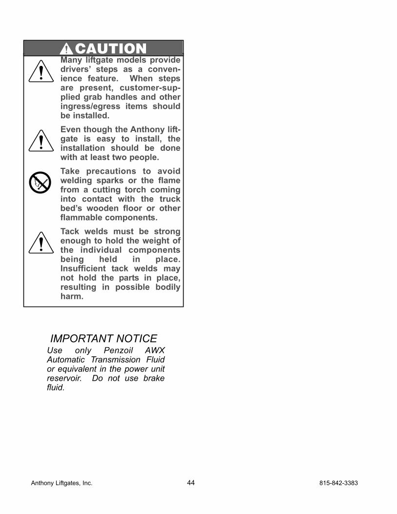
Many liftgate models providedrivers’ steps as a conven-ience feature. When stepsare present, customer-sup-plied grab handles and otheringress/egress items shouldbe installed.
Even though the Anthony lift-gate is easy to install, theinstallation should be donewith at least two people.
Take precautions to avoidwelding sparks or the flamefrom a cutting torch cominginto contact with the truckbed’s wooden floor or otherflammable components.
Tack welds must be strongenough to hold the weight ofthe individual componentsbeing held in place.Insufficient tack welds maynot hold the parts in place,resulting in possible bodilyharm.
CAUTION
IMPORTANT NOTICEUse only Penzoil AWXAutomatic Transmission Fluidor equivalent in the power unitreservoir. Do not use brakefluid.
815-842-3383 45 Anthony Liftgates, Inc.
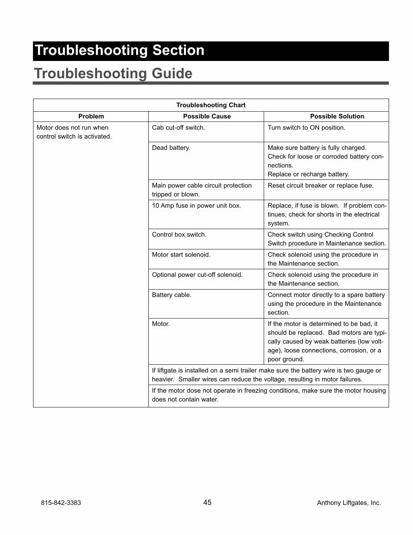
Troubleshooting Chart
Problem Possible Cause Possible Solution
Motor does not run when Cab cut-off switch. Turn switch to ON position.
control switch is activated.
Dead battery. Make sure battery is fully charged.
Check for loose or corroded battery con-
nections.
Replace or recharge battery.
Main power cable circuit protection Reset circuit breaker or replace fuse.
tripped or blown.
10 Amp fuse in power unit box. Replace, if fuse is blown. If problem con-
tinues, check for shorts in the electrical
system.
Control box switch. Check switch using Checking Control
Switch procedure in Maintenance section.
Motor start solenoid. Check solenoid using the procedure in
the Maintenance section.
Optional power cut-off solenoid. Check solenoid using the procedure in
the Maintenance section.
Battery cable. Connect motor directly to a spare battery
using the procedure in the Maintenance
section.
Motor. If the motor is determined to be bad, it
should be replaced. Bad motors are typi-
cally caused by weak batteries (low volt-
age), loose connections, corrosion, or a
poor ground.
If liftgate is installed on a semi trailer make sure the battery wire is two gauge or
heavier. Smaller wires can reduce the voltage, resulting in motor failures.
If the motor dose not operate in freezing conditions, make sure the motor housing
does not contain water.
Troubleshooting Section
Troubleshooting Guide
Anthony Liftgates, Inc. 46 815-842-3383
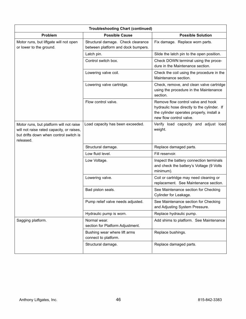
Troubleshooting Chart (continued)
Problem Possible Cause Possible Solution
Motor runs, but liftgate will not open Structural damage. Check clearance Fix damage. Replace worn parts.
or lower to the ground. between platform and dock bumpers.
Latch pin. Slide the latch pin to the open position.
Control switch box. Check DOWN terminal using the proce-
dure in the Maintenance section.
Lowering valve coil. Check the coil using the procedure in the
Maintenance section.
Lowering valve cartridge. Check, remove, and clean valve cartridge
using the procedure in the Maintenance
section.
Flow control valve. Remove flow control valve and hook
hydraulic hose directly to the cylinder. If
the cylinder operates properly, install a
new flow control valve.
Motor runs, but platform will not raise
will not raise rated capacity, or raises,
but drifts down when control switch is
released.
Structural damage. Replace damaged parts.
Low fluid level. Fill reservoir.
Low Voltage. Inspect the battery connection terminals
and check the battery’s Voltage (9 Volts
minimum).
Lowering valve. Coil or cartridge may need cleaning or
replacement. See Maintenance section.
Bad piston seals. See Maintenance section for Checking
Cylinder for Leakage.
Pump relief valve needs adjusted. See Maintenance section for Checking
and Adjusting System Pressure.
Hydraulic pump is worn. Replace hydraulic pump.
Sagging platform. Normal wear. Add shims to platform. See Maintenance
section for Platform Adjustment.
Bushing wear where lift arms Replace bushings.
connect to platform.
Structural damage. Replace damaged parts.
Load capacity has been exceeded. Verify load capacity and adjust load
weight.
815-842-3383 47 Anthony Liftgates, Inc.
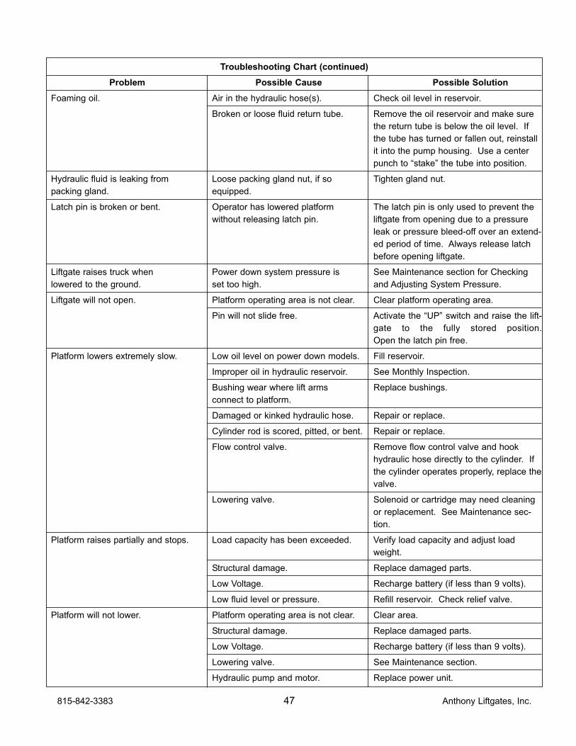
Troubleshooting Chart (continued)
Problem Possible Cause Possible Solution
Foaming oil. Air in the hydraulic hose(s). Check oil level in reservoir.
Broken or loose fluid return tube. Remove the oil reservoir and make sure
the return tube is below the oil level. If
the tube has turned or fallen out, reinstall
it into the pump housing. Use a center
punch to “stake” the tube into position.
Hydraulic fluid is leaking from Loose packing gland nut, if so Tighten gland nut.
packing gland. equipped.
Latch pin is broken or bent. Operator has lowered platform The latch pin is only used to prevent the
without releasing latch pin. liftgate from opening due to a pressure
leak or pressure bleed-off over an extend-
ed period of time. Always release latch
before opening liftgate.
Liftgate raises truck when Power down system pressure is See Maintenance section for Checking
lowered to the ground. set too high. and Adjusting System Pressure.
Liftgate will not open. Platform operating area is not clear. Clear platform operating area.
Pin will not slide free. Activate the “UP” switch and raise the lift-
gate to the fully stored position.
Open the latch pin free.
Platform lowers extremely slow. Low oil level on power down models. Fill reservoir.
Improper oil in hydraulic reservoir. See Monthly Inspection.
Bushing wear where lift arms Replace bushings.
connect to platform.
Damaged or kinked hydraulic hose. Repair or replace.
Cylinder rod is scored, pitted, or bent. Repair or replace.
Flow control valve. Remove flow control valve and hook
hydraulic hose directly to the cylinder. If
the cylinder operates properly, replace the
valve.
Lowering valve. Solenoid or cartridge may need cleaning
or replacement. See Maintenance sec-
tion.
Platform raises partially and stops. Load capacity has been exceeded. Verify load capacity and adjust load
weight.
Structural damage. Replace damaged parts.
Low Voltage. Recharge battery (if less than 9 volts).
Low fluid level or pressure. Refill reservoir. Check relief valve.
Platform will not lower. Platform operating area is not clear. Clear area.
Structural damage. Replace damaged parts.
Low Voltage. Recharge battery (if less than 9 volts).
Lowering valve. See Maintenance section.
Hydraulic pump and motor. Replace power unit.

Anthony LIftgates, Inc.Magnum Tuckunder Hydraulic Liftgate Inspection Record
Date of Inspection Notes, observations, maintenance performed, etc.
Anthony Liftgates, Inc. 48 815-842-3383
Limited Warranty
Magnum Tuckunder
3 yrs Mechanical + 3 yrs
Electric/Hydraulic
Thank you for purchasing an Anthony lift-gate. We strive to produce the most trou-ble free and reliable liftgates in the market.We believe you will experience years ofreliable operation and minimum downtimeinterruptions. To further insure your confi-dence in Anthony, this warranty will coveryour unit for 3 years or 8,000 cycles(whichever occurs first) onmechanical/structure, electrical, andhydraulic operating parts. This warranty isextended to the original purchaser (useronly) and is not transferable. The warran-ty term begins from the date of shipmentfrom our factory or warehouse.
Anthony Liftgates Inc. will cover all failedcomponents during the warranty period.Labor will be provided under our Flat RateWarranty Schedule, in effect at the time ofthe part failure, and includes diagnosistime. Contact Anthony for current reim-bursement amounts. For repairs NOT list-ed on the Flat Rate Warranty Schedule,contact the Anthony Warranty Departmentfor approved reimbursement, prior to per-forming repairs. Anthony Liftgates Inc.reserves the right of determination ofwhether a component is defective or hasfailed. This warranty applies to Anthonyliftgates installed, operated, and main-tained in accordance with AnthonyLiftgates Inc. installation, operation, andmaintenance manuals, videos, etc.
Certain Anthony models have publishedLifetime Warranties on listed components,as published in current literature. Thisadditional coverage will be detailed on thepublished operation components, provid-ing the unit has been operated and main-tained within the intended usage.
Anthony Liftgates, Inc. will process allclaims and determine their eligibility forauthorization upon the receipt of the failedpart, the identification of the claimant, andthe liftgate serial number. All parts mustbe returned freight prepaid and followingthe instructions given by the AnthonyWarranty Department. Freight collectshipments will not be accepted.
PLEASE NOTE THAT NO CLAIMS WILLBE PROCESSED WITHOUT THE PART,THE CLAIMANT’S INFORMATION, ANDTHE LIFTGATE SERIAL NUMBER.
Claims not submitted within 30 days ofrepair date will be denied.
NOTE: ALL CLAIMS MUST BE COM-PLETED ON THE ANTHONY LIFTGATESINC. WARRANTY CLAIM FORM.
This form provides all the necessary infor-mation.
Upon approval of the claim, Anthony will,at the direction of the claimant, return areplacement part and labor allowance, ora parts credit based on current distributornet pricing, and the appropriate flat ratelabor allowance.
815-842-3383 49 Anthony Liftgates, Inc.
Anthony Liftgates, Inc. is not responsibleor liable for loss of time, cost, labor, mate-rial, profits, direct or indirect damagescaused by failed components, whetherdue to rights arising under purchase,order, contract of sale or independentlythereof, and whether or not such claim isbased on contract, tort, or warranty. Thesale of products of Anthony Liftages, Inc.under any other warranty or guaranteeexpress or implied is not authorized. Thiswarranty does not cover misuse, abuse,damage, or product finish, normal wear,maintenance adjustments, careless ornegligence of use or maintenance.Modifications to our product are not cov-ered unless prior authorized by Anthony.
Purchased Parts warranty is 1 year fromdate of purchase and covers replacementof part only.
If you require assistance or have ques-tions, please contact Anthony Liftgates Inc.at 815-842-3383.
NOTE: Most (not all) Anthony liftgate mod-els incorporate our Service-Free feature.Service-Free refers to the fact that thesemodels require no routine or scheduledlubrication of the major pivot points thatcontain our service-free bushings. Normalrepair and maintenance of your liftgate,per our instruction, is necessary for ALLAnthony liftgates.
Anthony Liftgates, Inc.1037 W. Howard St. P.O. Box 615Pontiac, IL 61764-0615
PH: 815-842-3383FAX: 815-844-3612E-Mail: [email protected]
Warranty Policy and Procedure
All warranty claims must be completed onthe Anthony Liftgates Warranty ClaimForm utilizing the Flat Rate WarrantySchedule. See the current rates as listedfor each model. Using this process willallow for quick and accurate credit pay-ment.
Claims will not be processed without thefailed part returned (pre-paid) to AnthonyLiftgates, and the warranty claim formcompleted.
NOTE: When returning defective parts forwarranty consideration, be sure to callahead for a Return Authorization Number.
If you require further assistance or havequestions, please contact the AnthonyLiftgates Warranty Dept. at 815-842-3383or email [email protected].
Anthony Liftgates, Inc. 50 815-842-3383

Notes
815-842-3383 51 Anthony Liftgates, Inc.

Notes
Anthony Liftgates, Inc. 52 815-842-3383


Form No. L-401 Revision 09/15
Anthony Liftgates, Inc.1037 W. Howard Street • P.O. Box 615 • Pontiac, IL 61764-0615Ph: 815.842.3383 • Fax: 815.844.3612 • Toll Free: 800.482.0003www.anthonyliftgates.com