antennas for gigabit wireless...
TRANSCRIPT

Millimetre WaveAntennas forGigabit WirelessCommunicationsA Practical Guide to Design andAnalysis in a System Context
Kao-Cheng Huang
University of Greenwich, UK
David J. Edwards
University of Oxford, UK
A John Wiley and Sons, Ltd, Publication

Millimetre Wave Antennasfor Gigabit WirelessCommunications

Millimetre WaveAntennas forGigabit WirelessCommunicationsA Practical Guide to Design andAnalysis in a System Context
Kao-Cheng Huang
University of Greenwich, UK
David J. Edwards
University of Oxford, UK
A John Wiley and Sons, Ltd, Publication
This edition first published 2008© 2008 John Wiley & Sons Ltd
Registered officeJohn Wiley & Sons Ltd, The Atrium, Southern Gate, Chichester, West Sussex, PO19 8SQ, United Kingdom
For details of our global editorial offices, for customer services and for information about how to apply forpermission to reuse the copyright material in this book please see our website at www.wiley.com.
The right of the author to be identified as the author of this work has been asserted in accordancewith the Copyright, Designs and Patents Act 1988.
All rights reserved. No part of this publication may be reproduced, stored in a retrieval system, or transmitted,in any form or by any means, electronic, mechanical, photocopying, recording or otherwise, except as permittedby the UK Copyright, Designs and Patents Act 1988, without the prior permission of the publisher.
Wiley also publishes its books in a variety of electronic formats. Some content that appears in printmay not be available in electronic books.
Designations used by companies to distinguish their products are often claimed as trademarks. All brand namesand product names used in this book are trade names, service marks, trademarks or registered trademarks oftheir respective owners. The publisher is not associated with any product or vendor mentioned in this book.This publication is designed to provide accurate and authoritative information in regard to the subject mattercovered. It is sold on the understanding that the publisher is not engaged in rendering professional services.If professional advice or other expert assistance is required, the services of a competent professional shouldbe sought.
Library of Congress Cataloging-in-Publication Data
Huang, Kao-Cheng.Millimetre wave antennas for gigabit wireless communications : a practical guideto design and analysis in a system context / Kao-Cheng Huang, David J. Edwards.
p. cm.Includes bibliographical references and index.ISBN 978-0-470-51598-3 (cloth)1. Microwave antennas. 2. Gigabit communications. 3. Milimeter waves.I. Edwards, David J. II. Title.TK7871.67.M53H83 2008621.382′4—dc22
2008013165
A catalogue record for this book is available from the British Library
ISBN 978-0-470-51598-3 (HB)
Set in 10/12pt Times by Integra Software Services Pvt. Ltd, Pondicherry, IndiaPrinted in Singapore by Markono Print Media Pte Ltd, Singapore.

Contents
Preface ix
List of Abbreviations xi
1 Gigabit Wireless Communications 11.1 Gigabit Wireless Communications 11.2 Regulatory Issues 7
1.2.1 Europe 71.2.2 United States 81.2.3 Japan 91.2.4 Industrial Standardisation 9
1.3 Millimetre Wave Characterisations 121.3.1 Free Space Propagation 131.3.2 Millimetre Wave Propagation Loss Factors 131.3.3 Atmospheric Losses 14
1.4 Channel Performance 141.5 System Design and Performance 22
1.5.1 Antenna Arrays 221.5.2 Transceiver Architecture 23
1.6 Antenna Requirements 261.7 Link Budget 301.8 Summary 34References 34
2 Critical Antenna Parameters 372.1 Path Loss and Antenna Directivity 382.2 Antenna Beamwidth 452.3 Maximum Possible Gain-to-Q 462.4 Antenna Polarisation 50
2.4.1 Polarisation Diversity 56References 58
3 Planar Antennas 613.1 Printed Antennas 613.2 Slot Antennas 72
3.2.1 Standard Slot Antenna 723.2.2 Tapered Slot Antennas 73

vi CONTENTS
3.3 Quasi-Yagi Antennas 753.4 Bow-Tie Antennas 763.5 Reflector Antennas 783.6 Millimetre Wave Design Considerations 843.7 Production and Manufacture 85
3.7.1 Fine Line Printing 853.7.2 Thick Film 863.7.3 Thin Film 863.7.4 System-on-Chip 87
References 87
4 Horn Antennas 914.1 Waveguide Modes 914.2 Multimode Horn Antennas 944.3 Integrated Horn 984.4 Conical Horns and Circular Polarisation 1024.5 Tilt Horn 1104.6 Dielectric Sectoral Horn 111References 112
5 Dielectric Antennas 1155.1 Dielectric Resonator Antennas 1155.2 Dielectric Rod Antennas 1215.3 Maximum Gain Rod Antennas 1265.4 The Dual Rod Antenna 1275.5 Patch-Fed Circular Rod Antennas 1305.6 Rod Arrays and Phase Compensation 1365.7 Optimisation of a Rod Antenna 139References 141
6 Lens Antennas 1456.1 Luneberg Lens 1466.2 Hemispherical Lens 1496.3 Extended Hemispherical Lens 1516.4 Off-Axis Extended Hemispherical Lens 1576.5 Planar Lens Array 1616.6 Metal Plate Lens Antennas 164References 166
7 Multiple Antennas 1717.1 The 60 GHz Multibeam Antenna 1717.2 Antenna Arrays 1767.3 Millimetre Wave Arrays 180
7.3.1 Printed Arrays 1807.3.2 Waveguide Arrays 1827.3.3 Leaky-Wave Arrays 184
7.4 Mutual Coupling between Antennas 186References 194
CONTENTS vii
8 Smart Antennas 1978.1 Beam-Switching Antennas 1998.2 Beam-Steering/Forming Antennas 205
8.2.1 Electronic Beamforming 2068.3 Millimetre Wave MIMO 212
8.3.1 Beamforming Layer 2158.3.2 Spatial Multiplexing Layer 217
8.4 Mode-Tracking Antennas 218References 224
9 Advanced Antenna Materials 2279.1 Low-Temperature Co-fired Ceramics 2289.2 Liquid Crystal Polymer 2339.3 CMOS 2389.4 Meta Materials 2419.5 High-Temperature Superconducting Antenna 2459.6 Nano Antennas 249References 249
10 High-Speed Wireless Applications 25510.1 V-Band Antenna Applications 255
10.1.1 Wireless Personal Area Networks (WPANs) 25610.1.2 Wireless HDMI 25610.1.3 Point-to-Point 60 GHz Links 25710.1.4 Broadcasting a Video Signal Transmission System in a Sports Stadium 25710.1.5 Intervehicle Communication System 25810.1.6 Multigigabit File Transmission 25810.1.7 Current Developments 258
10.2 E-Band Antenna Applications 26110.2.1 Private Networks/Enterprise LAN Extensions 26110.2.2 Fibre Extensions 26210.2.3 Fibre Back-up/Diversity Connections 26210.2.4 Military Communications and Surveillance Systems 26210.2.5 Secure Applications 263
10.3 Distributed Antenna Systems 26410.4 Wireless Mesh Networks 267References 270
Index 273


Preface
This book presents antenna design and analysis at the level to produce an understanding ofthe interaction between a wireless system and its antenna, so that the overall performance canbe predicted. Gigabit wireless communications require a considerable amount of bandwidth,which can be supported by millimetre waves. Millimetre wave technology has now come ofage, and at the time of writing the standards of IEEE 802.15.3c, WirelessHDTM and ECMA areon schedule to be finalised. The technology has attracted new commercial wireless applicationsand new markets, such as the capacity for high-speed downloading and wireless high-definitionTVs. This book summarises and reports the extensive research over recent years and emphas-ises the importance and requirements of antennas for gigabit wireless communications, withan emphasis on wireless communications in the 60 GHz ISM band and in the E-band. Thisbook I reviews the particular requirements for this application and addresses the design andfeasibility of millimetre wave antennas; such as planar antennas, rod antennas and antennaarrays. Examples of designs are included, along with a detailed analysis of their performance.In addition, this book includes a bibliography of current research literature and patents in thissubject area. Finally, the applications of these antennas are discussed in the light of differentforthcoming wireless standards.
Millimetre Wave Antennas for Gigabit Wireless Communications endeavours to offer acomprehensive treatment of antennas based on electronic consumer applications, providinga link to applications of computer-aided design tools and advanced materials and technolo-gies. The major features of this book include a discussion of the many novel millimetre waveantenna configurations available with newly reported design techniques and methods.
Although it contains some introductory material, this book is intended to provide a collectionof millimetre wave antenna design considerations for communication system designers andantenna designers. The book should also act as a reference for postgraduate students, research-ers and engineers in millimetre wave engineering and an introduction to the various designconsiderations. It can also be used for millimetre wave teaching. A summary of each chapteris given below.
Chapter 1 introduces the near-term developments in millimetre wave communications. Theimportance and requirements of millimetre wave antennas are discussed based on channelperformance, link budget, and applications in line-of-sight and non-line-of-sight scenarios.Sections addressing system-level considerations include references to subsequent chaptersthat contain a more detailed treatment of antenna design.
Chapters 2 to 8 address conventional configurations of millimetre wave antennas.Chapter 2 considers several critical factors that limit the performance of millimetre wave
antennas.As the antenna design has become critical in wireless communications, the limitationsof antenna design are also discussed in this chapter.

x PREFACE
Chapter 3 describes the variety of millimetre wave planar antennas, and lists basic feedingmethods and useful references on a wide variety of techniques for producing low-profileantennas.
Chapter 4 deals with millimetre wave integrated horn antennas. The chapter includes adiscussion of circular polarisation optimisation techniques, such as those for array antennas.With circular waveguide modes that can be used for mode tracking described in Chapter 8.
Chapter 5 addresses low cost and high directivity of millimetre wave rod antennas. Differentfeeding methods, maximum gain, and beam tilting are discussed in detail. With multiple-rodantennas that can be used as beam-switching antennas discussed in Chapter 7.
Chapter 6 describes the variety of millimetre wave lens antennas, relevant feeding methodsand novel architectures. Lens antennas, with the advantages of light weight and small height,are identified as designs that can be used for new applications.
Chapter 7 discusses millimetre wave multibeam antennas and their construction. Novelantennas with advanced radiation characteristics have been demonstrated. Some of the effectsof mutual coupling of signals and noises between array elements are covered. This interactionmodifies the active array element patterns and can cause impedance changes during scanning.
Chapter 8 focuses on smart antennas and their usage in wireless communications. Wide-ranging technologies such as beam switching, beam steering, MIMO and mode tracking, thatsatisfy special needs are considered. These technologies could produce low-profile high-gain electronic scanning systems in conjunction with the antenna elements described inChapters 3 to 7.
Chapter 9 explores millimetre wave antenna materials and manufacturing techniques.Materials technologies are discussed such as LTCC, LCP, CMOS, high-temperature super-conductors, carbon nanotubes, etc. New materials offer new design concepts and promisefuture exciting antenna technology trends.
Finally, chapter 10, extrapolates the wireless applications of millimetre wave antennas ina envisaged future market. This book only briefly addresses the details of electromagneticanalysis, with the fundamentals of the subject requiring a more detailed study than can begiven in this system design-oriented book.
First of all, the authors wish to acknowledge the copyright permission from IEEE (US),European Microwave Association (Belgium), John Wiley & Sons, Inc. (US), ERA (UK) andSu Khiong Yong (US).
The authors are indebted to many researchers for their published works, which were richsources of reference upon which this book reports and summarises. Their sincere gratitudeextends to the Editor, Sarah Hinton, and the reviewers for their support in the writing of thisbook. The help provided by Tiina Ruonamaa and other members of the staff at John Wiley &Sons, Ltd is most appreciated. The authors also wish to thank their colleagues at the Universityof Oxford, and University of Greenwich.
In addition, Kao-Cheng Huang would like to thank Prof. Mook-Seng Leong, NationalUniversity of Singapore (Singapore), Prof. Rüdiger Vahldieck, ETH (Switzerland),Prof. Ban-Leong Ooi, National University of Singapore (Singapore), Dr David Haigh, ImperialCollege (UK), Prof. Francis Lau, Hong Kong Polytechnic University (China), Dr H.M. Shen,University of Edinburgh (UK), Dr Chris Stevens, University of Oxford (UK) and Dr Jia-ShengHong, Heriot-Watt University (UK) for their many years of support. David Edwards wouldalso like to thank Charlotte Edwards for her help in the final stages of the book. Note: Duringthe later stages of the production of this book Dr Kao-Cheng Huang was taken seriously ill.The book has been completed from his notes and we apologise for any resulting omissions.
List of Abbreviations
A/V audio/visualADC analogue-to-digital conversionAP access pointsAR axial ratioARIB Association of Radio Industries and BusinessASP aperture stacked patchBER bit error rateCB-FGC conductor-backed finite ground coplanarCBCPW conductor-backed coplanar waveguideCCS complementary conducting stripCEPT European Conference of Postal and Telecommunications AdministrationsCPS coplanar striplineCTE coefficient of thermal expansionDAS distributed antenna systemsDBF digital beamformingDLA discrete lens arrayDoA direction of arrivalDRA dielectric resonator antennaEBGs electromagnetic bandgapsECC Electronic Communications CommitteeECMA European Computer Manufacture AssociationEIRP equivalent isotropic radiated powerERC European Radiocommunications CommitteeESPRIT Estimation of Signal Parameters via Rotational Invariance TechniquesETSI European Telecommunications Standards InstituteFCC Federal Communication CommissionsFDA Food and Drug AdministrationFDTD finite-difference time-domainFLA filter–lens arrayFPC Fabry–Perot cavityFT Fourier transformGO geometric opticsGSM Global System for Mobile CommunicationsHDMI high-definition multimedia interface
xii LIST OF ABBREVIATIONS
HDTV high-definition televisionHEM hybrid electromagneticHPBW half-power beamwidthHTS high-temperature superconductorsIC-SMT Industry Canada Spectrum Management and TelecommunicationsISM industrial, scientific and medicalISPs Internet Service ProvidersIVC Inter-Vehicle CommunicationsLA lens arrayLCP liquid crystal polymerLHCP left-hand circular polarisationLHM left-handed materialsLNA low-noise amplifierLOS line-of-sightLPD low probability of detectLPI low probability of interceptLTCC low-temperature co-fired ceramicMANETs mobile ad hoc networksMCM multichip modulesMEMS microelectromechanical systemMIMO multi-input multi-outputMMIC monolithic-microwave integrated circuitMPHPT Ministry of Public Management, Home Affairs, Posts, and TelecommunicationsMSK minimum shift keyingMT mobile terminalNLOS non-line-of-sightOFDM orthogonal frequency division multiplexingOMT orthomode transducerOOK on/off keyingPA 1. power amplifier
2. phased arrayPAPR peak-to-average power ratioPCB printed circuit boardPDA personal data assistantPHY physical layerPMP portable media playerPRS partially reflective surfacePS portable stationPTHs plated through holesQPSK quadrature phase-shift keyingRAUs radio access unitsRF radio frequencyRHCP right-hand circular polarisationRRH remote radio headsSC single carrierSCBT single-carrier block transmission

LIST OF ABBREVIATIONS xiii
SIR signal-to-interferenceSNR signal-to-noise ratioSoC system-on-chipSoP system-on-packageSP3T single-pole triple-throwSSFIP strip slot foam inverted patch antennaULA uniform linear arraysUWB ultra-widebandVCC voltage-controlled oscillatorWLANs wireless local area networksWMN wireless mesh networkWPANs wireless personal area networks


1Gigabit Wireless Communications
The demand for high data rate and high integrity services seems set to grow for the foreseeablefuture. In this chapter the basic ideas and application areas for gigabit Ethernet are introduced,and the requirements for high-performance networks are described. The role of the antenna inthese systems is addressed, and consideration of the performance parameters outlined.
This chapter is organised as follows. Section 1.1 describes a number of applicationscenarios and highlights the requirements for a specific application, namely uncompressedhigh-definition video streaming. Section 1.2 describes the worldwide regulatory effortsand standardisation activities. Section 1.3 presents the characteristics of millimetre waves.Section 1.4 presents measured propagation results and channel performance. Section 1.5describes system design and performance. Section 1.6 discusses the role of the antenna withinthe system and the technical challenges that need to be resolved for the full deployment of60 GHz radio networks. Section 1.7 describes the link budget, which is pivotal in determiningthe performance of the system. In this section noise is also examined, and its impact on linkbehaviour. Section 1.8 summarises the main points of the chapter.
1.1 Gigabit Wireless Communications
The adoption of each successive generation of Ethernet technology has been driven by econom-ics, performance demand, and the rate at which the price of the new generation has approachedthat of the old. As the cost of 100 Mbps Ethernet decreased and approached the previous cost of10 Mbps Ethernet, users rapidly moved to the higher performance standard. In January 2007,10 gigabit Ethernet over copper wiring was announced by the industry [1].Additionally, gigabitEthernet became economic (e.g. below $200) for server connections, and desktop gigabit con-nections have come within $10 or less of the cost of 100 Mbps technology. Consequently,gigabit Ethernet has become the standard for servers, and systems are now routinely orderedwith gigabit Network interface cards. Mirroring events in the wired world, as the prices ofwireless gigabit links approach the prices of 100 Mbps links, users are switching to the higher-performance product, both for traditional wireless applications, as well as for applications thatonly become practical at gigabit speeds.
Millimetre Wave Antennas for Gigabit Wireless Communications Kao-Cheng Huang and David J. Edwardsc© 2008 John Wiley & Sons, Ltd

2 GIGABIT WIRELESS COMMUNICATIONS
In terms of a business model, wireless communications have pointed towards an approach-ing need for gigabit speeds and longer-range connectivity as the applications emerge for homeaudio/visual (A/V) networks, high-quality multimedia, voice and data services. Current wire-less local area networks (WLANs) offer peak rates of 54 Mb/s, with 200–540 Mb/s, such asIEEE 802.11n, becoming available soon. However, even 500 Mb/s is inadequate when facedwith the demand for higher access speed from rich media content and competition from 10 Gb/swired LANs. In addition, future homeA/V networks will require a Gb/s data rate to support mul-tiple high-speed, high-definition A/V streams (e.g. carrying an uncompressed high-definitionvideo at resolutions of up to 1920 × 1080 progressive scans, with latencies ranging from 5 to15 ms) [2].
Based on the technical requirements of applications for high-speed wireless systems, bothindustry and the standardisation bodies need to take into account the following issues:
1. Pressure on data rate increases will persist.2. There is a need for advanced domestic applications such as high-definition wireless
multimedia, which demand higher data rates.3. Data streaming and download/memory back-up times for mobile and personal devices will
also place demands on the shared resource, and user models point to very short dwell timesfor these downloads.
Some approaches, such as IEEE 802.11n, are improving data rates by evolving the exist-ing WLANs standards to increase the data rate; to up to 10 times faster than IEEE 802.11aor 802.11g. Others, such as the ultra-wideband (UWB) are pursuing much more aggressivestrategies, such as sharing spectra with other users.Another approach that will no doubt be takenwill be the time-honoured strategy of moving to higher, unused and unregulated millimetrewave frequencies.
Despite millimetre wave technology having been established for many decades, the mil-limetre wave systems available have mainly been deployed for military applications. Withthe advances in process technologies and low-cost integration solutions, this technology hasstarted to gain a great deal of momentum from academia, industry and standardisation bodies.In very broad terms, millimetre wave technology can be classified as occupying the electro-magnetic spectrum that spans between 30 and 300 GHz, which corresponds to wavelengthsfrom 10 to 1 mm. In this book, the main focus will be on the 60 GHz industrial, scientific andmedical (ISM) band (unless otherwise specified, the terms “60 GHz’’ and “millimetre wave’’will be used interchangeably), which has emerged as one of the most promising candidates formultigigabit wireless indoor communication systems.
Although the IEEE 802.11n standard will improve the robustness of wireless communica-tions, only a modest increase in wireless bandwidth is provided and the data rate is still lowerthan 1 Gb/s. Importantly, 60 GHz technology offers various advantages over currently pro-posed or existing communications systems. One of the deciding factors that makes 60 GHztechnology attractive and has prompted significant interest recently, is the establishment of(relatively) huge unlicensed bandwidths (up to 7 GHz) that are available worldwide. The spec-trum allocations are mainly regulated by the International Telecommunication Union. Thedetails for band allocation around the world can be found in Section 1.2.
While this is comparable to the unlicensed bandwidth allocated for ultra-wideband purposes(∼2–10 GHz), the 60 GHz band is continuous and less restricted in terms of power limits (also

GIGABIT WIRELESS COMMUNICATIONS 3
there are less existing users). This is due to the fact that the UWB system is an overlay sys-tem and thus subject to different considerations and very strict regulation. The large band at60 GHz is in fact one of the largest unlicensed spectral resources allocated in history. This hugebandwidth offers potential in terms of capacity and flexibility and makes 60 GHz technologyparticularly attractive for gigabit wireless applications. Although 60 GHz regulations allowmuch higher transmit power compared to other existing wireless local area networks (e.g. max-imum 100 mW for IEEE 802.11 a/b/g) and wireless personal area network (WPAN) systems, thehigher transmit power is necessary to overcome the higher path loss at 60 GHz (see Table 1.1).
Table 1.1 Path loss and transmit power comparison for differentwireless standards
10 m path loss(dB)
Maximum transmitpower (mW)
802.11a 66 40802.11b/g 60 100802.15.3c 88 500
In addition, the typical 480 Mbps bandwidth of UWB cannot fully support broadcast videoand therefore the data packets need to be recompressed. This forces manufacturers to utiliseexpensive encoders and more memory into their systems, in effect losing video content andadding latency in the process. Therefore, 60 GHz technology could actually provide betterresolution, with less latency and cost for television, DVD players and other high-definitionequipment, compared to UWB.
Taking into consideration the development of consumer electronics, currently the IEEE802.15.3c standard [3] provides 1–3 Gb/s wireless personal area network solutions, projectedfor introduction in the years 2008 to 2009. Also, WiMedia 2.0 [4], which can be used for largefile transfer applications, is to be developed, so the target is to have a data rate of 5 Gb/s orhigher raw bit rates and with more than a 10 m range for indoor applications.
Figure 1.1 shows the development and the trend of wireless standards. Advanced wirelesstechnology should always adopt timelines/milestones to increase data rates by ∼5 to 10 timesevery 3 to 4 years to keep up with the pace of projected demand.
While the high path loss seems to be a disadvantage at 60 GHz, it does however confine the60 GHz power and system operation in an indoor environment. Hence, the effective interferencelevels for 60 GHz are less severe than those systems located in the congested 2–2.5 GHz and5–5.8 GHz regions. In addition, higher frequency re-use can also be achieved over a veryshort distance in an indoor environment, thus allowing a very high throughput network. Thecompact size of the 60 GHz radio also permits multiple antenna solutions at the user terminalthat are otherwise difficult, if not impossible, at lower frequencies. Compared to a 5 GHzsystem, the form factor of millimetre wave systems is approximately 140 times smaller andcan be conveniently integrated into consumer electronic products, but it will require new designmethodologies to meet modern communication needs.
Designing a very high-speed wireless link that offers good quality-of-service and rangecapability presents a significant research and engineering challenge. Ignoring fading for themoment, in theory, the 1 Gb/s data rate requirement can be met, if the product of bandwidth

4 GIGABIT WIRELESS COMMUNICATIONS
WPAN
WLAN
Gen 3: 25-50 Gb/sGen 2: 5-10 Gb/s
802.15.3c
802.11n
802.11a
3.5G3G
2G
802.11b
Cellular/WAN
UWB
19950.01M
0.1M
1M
10M
100M
1G
10G
2000 2005 2010 2015Year
Dat
a R
ate
(bps
)
Figure 1.1 Data rate projections over time [5]
(in units of Hz) and spectral efficiency (in b/s per Hz units) equals 109. As shall be describedin the following sections, a variety of cost, technology and regulatory constraints make sucha solution very challenging.
Despite the various advantages offered, millimetre wave based communications suffer anumber of critical problems that must be resolved. Figure 1.2 shows the data rates and rangerequirements for a number of WLAN and WPAN systems. Since there is a need to distinguishbetween different standards for broader market exploitation, the IEEE 802.15.3c standard ispositioned to provide gigabit rates and a longer operating range. At these rates and ranges,it will be a difficult task for millimetre wave systems to provide a sufficient power marginto ensure a reliable communication link. Furthermore, the delay spread of the channel underconsideration is another limiting factor for high-speed transmission. Large delay spread valuescan easily increase the complexity of the system beyond the practical limit for equalisation [6].
Figure 1.2 Data rates and range requirements for WLAN and WPAN standards and applications.Millimetre wave technology, i.e. IEEE 802.15.3c, is aiming for very high data rates [6]
If a 10 mW power input to the antenna is assumed with a 10 dBi gain based on a highlyintegrated, low-cost design with a steerable beam at 60 GHz, a Shannon capacity curve isproduced, as shown in Figure 1.3. The formula used to derive these curves is presented inEquations (1.3) and (1.4) in Section 1.4.

GIGABIT WIRELESS COMMUNICATIONS 5
10
2
4
6
8
10
12
14
16
18
20
2 3 4 5Data rate (Gb/s)
UWB
60 GHzD
ista
nce
(m)
Figure 1.3 Shannon’s capacity curve in a 1 GHz occupied bandwidth for 60 GHz versus UWB (noisefigure is set at 8 dB) [5]
In the search for the provision of higher data rates, radio systems have tended to look athigher frequencies where an unregulated spectrum is available. As an alternative, a (free space)wireless optical LAN also competes as one of the communication technologies that are ableto offer a significant unregulated spectrum. Diffuse optical networks use wide- angle sourcesand scatter from surfaces in the room to provide optical ‘ether’ similar to that which would beobtained using a local radio transmitter [7]. This produces coverage that is robust to blocking,but the multiple paths between the source and receiver cause dispersion of the channel, thuslimiting its performance. Additionally optical transmitters launch extremely high power, anddynamic equalisation is required for high bandwidth operation.
Optical networks have the potential to offer significant advantages over radio approaches,within buildings or in spaces with limited coverage. Many current systems use directed line-of-sight paths between transmitter and receiver [8]. These can provide data rates of hundredsof megabits per second and above, depending on particular parameters. However, the coveragearea provided by a single channel can be quite small, so that providing area coverage, and theability to roam, presents a major challenge. Line-of-sight channels can also be blocked, asthere is no alternative scattered path between the transmitter and receiver, and this presents amajor challenge in network design [7]. Multiple-base stations within a room would providecoverage in this case, and optical or fixed connections could be used between the stations.A commercial line-of-sight system is currently offered by Victor Company of Japan, Limited(JVC), giving 10 Mb/s Ethernet connections [9].
In general, optical channels are subject to eye safety regulation, which is difficult to meet,particularly for line-of-sight channels [7]. Typically optical LANS work in the near- infraredregion (between 700 and 1000 nm) where optical sources and detectors are low cost andregulations are particularly strict. At longer wavelengths (1500 nm and above) the regulationsare much less stringent, although sources at this wavelength and power output are not widelyavailable [10].

6 GIGABIT WIRELESS COMMUNICATIONS
As previously mentioned, the other major problem for optical channels is that of blocking.Line-of-sight channels in particular are required for high-speed operation and these are by theirnature subject to blocking. Within a building, networks must be designed using appropriategeometries to avoid blocking, and this is usually solved by using multiple access points toallow complete coverage [10, 11].
Table 1.2 compares the characteristics of three technologies for gigabit communications:UWB radio, millimetre wave and wireless optics.
Table 1.2 Comparison of three new technologies for gigabit wireless communications [12–14]
Millimetre wave UWB radio Optical wireless
Advantage 1. High data rates (upto Gb/s)
2. Compatible withfibre opticnetworks at60 GHz
1. Low power2. Short range3. Low data4. Penetration through
obstacles in thetransmission path
1. High data rate2. Unlicensed and
unregulated.
Challenge 1. Low cost2. Low power
1. Matched filter problem2. Antenna parameter
trade-off
1. Atmospheric lossranging from10 dB/km(sunny) to350 dB/km(foggy)
2. Multi-user application3. No protection for the
link
Peer-to-peer Indoor/outdoor Indoor/outdoor Indoor/outdoor
Multiple-access
Indoor/outdoor Indoor Indoor
Data rate >1.25 Gb/s at 60 GHz∼10 Gb/s at122.5 GHz
500 Mbps within 10 m (FCC) ∼1.25 Gb/s (peer-to-peer)
Indoormaximumrange
Room area 76 m (station in commercialbuilding)
7 m (mobile) 10 m(station)
DC powerconsumption
High Low DC 5 V, 500 mA (mobile)
Maximum TXpower
500 mW (FCC15.255)
Maximum output power of1 W spread over spectrumMaximum power density:−41.3 dBm/MHz (FCC)
Power density should beless than 1 mW/cm2
(FDA)
Notes Antenna design is oneof the mainchallenges
1. Infrastructure orpeer-to-peer for indoorapplication
2. Only peer-to-peer forhand-held application(FCC)
Eye safety should beconsidered

REGULATORY ISSUES 7
1.2 Regulatory Issues
1.2.1 Europe
The European Telecommunications Standards Institute (ETSI) and European Conference ofPostal and Telecommunications Administrations (CEPT) have been working closely to estab-lish a legal framework for the deployment of unlicensed 60 GHz devices [15]. In general,the 59–66 GHz band has been allocated for mobile services without specific decision on theregulations, as shown in Figure 1.4. The CEPT Recommendation T/R 22–03 has provisionallyrecommended the use of the 54.25–66 GHz band for terrestrial and fixed mobile systems [16].However, this provisional allocation has been recently withdrawn [6].
Figure 1.4 The 60 GHz frequency spectrum in Europe (ISM: industry, science and medicine) [17]
In 2003, the European Radiocommunications Committee (ERC) within the European Con-ference of Postal and Telecommunications Administrations revised the European Table ofFrequencyAllocations and Utilisations [17]. The ERC also considered the use of the 57–59 GHzband for fixed services without requiring frequency planning [18]. Later, the Electronic Com-munications Committee (ECC) within the CEPT recommended the use of point-to-pointfixed services in the 64–66 GHz band [19]. In the most recent development, the ETSI pro-posed 60 GHz regulations to be considered by the Electronic Communications Committeeof the European Conference of Post and Telecommunications Administrations for WPANapplications [20]. Under this proposal, 9 GHz of unlicensed spectrum has been allocated for60 GHz operation. This band represents the union of the bands currently approved and underconsideration in the first quarter of 2007.
The frequency band being considered is 57–66 GHz. The spectrum allocation is shownin Figure 1.5 and Table 1.3. This is the amalgamation of the bands currently approved for
Figure 1.5 Geographically available 60 GHz spectrum and power
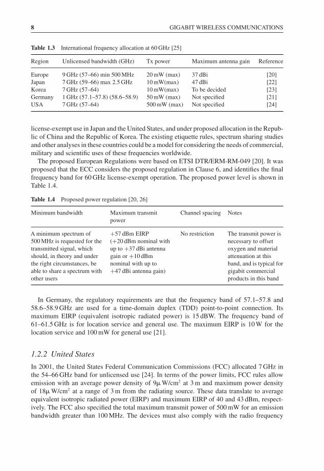
8 GIGABIT WIRELESS COMMUNICATIONS
Table 1.3 International frequency allocation at 60 GHz [25]
Region Unlicensed bandwidth (GHz) Tx power Maximum antenna gain Reference
Europe 9 GHz (57–66) min 500 MHz 20 mW (max) 37 dBi [20]Japan 7 GHz (59–66) max 2.5 GHz 10 mW(max) 47 dBi [22]Korea 7 GHz (57–64) 10 mW(max) To be decided [23]Germany 1 GHz (57.1–57.8) (58.6–58.9) 50 mW (max) Not specified [21]USA 7 GHz (57–64) 500 mW (max) Not specified [24]
license-exempt use in Japan and the United States, and under proposed allocation in the Repub-lic of China and the Republic of Korea. The existing etiquette rules, spectrum sharing studiesand other analyses in these countries could be a model for considering the needs of commercial,military and scientific uses of these frequencies worldwide.
The proposed European Regulations were based on ETSI DTR/ERM-RM-049 [20]. It wasproposed that the ECC considers the proposed regulation in Clause 6, and identifies the finalfrequency band for 60 GHz license-exempt operation. The proposed power level is shown inTable 1.4.
Table 1.4 Proposed power regulation [20, 26]
Minimum bandwidth Maximum transmitpower
Channel spacing Notes
A minimum spectrum of500 MHz is requested for thetransmitted signal, whichshould, in theory and underthe right circumstances, beable to share a spectrum withother users
+57 dBm EIRP(+20 dBm nominal withup to +37 dBi antennagain or +10 dBmnominal with up to+47 dBi antenna gain)
No restriction The transmit power isnecessary to offsetoxygen and materialattenuation at thisband, and is typical forgigabit commercialproducts in this band
In Germany, the regulatory requirements are that the frequency band of 57.1–57.8 and58.6–58.9 GHz are used for a time-domain duplex (TDD) point-to-point connection. Itsmaximum EIRP (equivalent isotropic radiated power) is 15 dBW. The frequency band of61–61.5 GHz is for location service and general use. The maximum EIRP is 10 W for thelocation service and 100 mW for general use [21].
1.2.2 United States
In 2001, the United States Federal Communication Commissions (FCC) allocated 7 GHz inthe 54–66 GHz band for unlicensed use [24]. In terms of the power limits, FCC rules allowemission with an average power density of 9� W/cm2 at 3 m and maximum power densityof 18� W/cm2 at a range of 3 m from the radiating source. These data translate to averageequivalent isotropic radiated power (EIRP) and maximum EIRP of 40 and 43 dBm, respect-ively. The FCC also specified the total maximum transmit power of 500 mW for an emissionbandwidth greater than 100 MHz. The devices must also comply with the radio frequency
REGULATORY ISSUES 9
(RF) radiation exposure requirements specified in Reference [24], Sections 1.307(b), 2.1091and 2.1093. After taking the RF safety issues into account, the maximum transmit power islimited to 10 dBm. Furthermore, each transmitter must transmit at least one transmitter iden-tification signal within a 1 s interval of the signal transmission. It is important to note that the60 GHz regulations in Canada, which is regulated by Industry Canada Spectrum Managementand Telecommunications (IC-SMT) [27], are harmonized with the US.
In October 2003, the FCC announced that the frequency bands from 71 to 76 GHz, 81 to86 GHz and 92 to 95 GHz were available for wireless applications [28]. The FCC chairmanheralded the ruling as opening a “new frontier’’ in commercial services and products [29]. Theallocation provides the opportunity for a broad range of new products and services, includinghigh-speed, point-to-point wireless local area networks and broadband Internet access at gigabitdata rates and beyond.
The 70, 80 and 90 GHz allocations are significant. Collectively referred to as E-band, thesethree allocations are the highest frequencies ever licensed by the FCC. The nearly 13 GHz ofallocated spectrum represents more bandwidth than all other previously existing commercialwireless spectrum combined. The ruling also permitted a novel licensing scheme, allowingcheap and fast frequency allocations to prospective users. All this was achieved at an unpre-cedented speed, from the initial petition to the formal release of the rules in scarcely more thantwo years.
1.2.3 Japan
In the year 2000, the Ministry of Public Management, Home Affairs, Posts, and Telecom-munications (MPHPT) of Japan issued 60 GHz radio regulations for unlicensed utilization inthe 59–66 GHz band [22]. The 54.25–59 GHz band is, however, allocated for licensed use.The maximum transmit power for the unlicensed use is limited to 10 dBm, with a maximumallowable antenna gain of 47 dBi. Unlike the arrangements in NorthAmerica, the Japanese reg-ulations specified that the maximum transmission bandwidth must not exceed 2.5 GHz. Thereis no specification for RF radiation exposure and transmitter identification requirements [22].
1.2.4 Industrial Standardisation
The first international industry standard that covered the 60 GHz band was the IEEE 802.16standard for local and metropolitan area networks [30]. However, this is a licensed band andis used for line-of-sight (LOS) outdoor communications for last mile connectivity. In Japan,two standards related to the 60 GHz band were issued by the Association of Radio Industriesand Business (ARIB), i.e. the ARIB-STD T69 and ARIB-STD T74 [31, 32]. The former isthe standard for millimetre wave video transmission equipment for a specified low-powerradio station (point-to-point system), while the latter is the standard for a millimetre waveultra-high-speed WLAN for specified low-power radio stations (point-to-multipoint). Bothstandards cover the 59–66 GHz band defined in Japan (see Table 1.5).
Interest in the 60 GHz radio continued to grow with the formation of a Millimetre WaveInterest Group and Study Group within the IEEE 802.15 Working Group for WPAN. In March2005, the IEEE 802.15.3c Task Group (TG3c) was formed to develop a millimetre wave-basedalternative physical layer (PHY) for the existing IEEE 802.15.3 WPAN Standard 802.15.3-2003 [33]. The developed PHY is aimed to support a minimum data rate of 2 Gb/s over a few

10 GIGABIT WIRELESS COMMUNICATIONS
Table 1.5 The 60 GHz standards in Japan
Code Standard name Note
ARIB STD-T69(July2004)
Millimetre-Wave Video Transmission Equipment forSpecified Low Power Radio Station Bandwidth: 1208 MHz
Tx power: 10 dBm Rxantenna gain: 0 dBi
ARIB STD-T69Revision(November 2005)
Millimetre-Wave Video Transmission Equipment forSpecified Low Power Radio Station (only the part ofthe revision from Version 2.0 to 2.1)
ARIB STD-T74(May 2001)
Millimetre-Wave Data Transmission Equipment forSpecified Low Power Radio Station (Ultra High SpeedWireless LAN System) Bandwidth: 200 MHz
Tx power: 10 dBm Rxantenna gain: 0 dBi
ARIB STD-T74Revision(November 2005)
Millimetre-Wave Data Transmission Equipment forSpecified Low Power Radio Station (Ultra High SpeedWireless LAN System) (only the part of the revisionfrom Version 1.0 to 1.1)
metres with optional data rates in excess of 3 Gb/s. This is the first standard that addressesmultigigabit wireless systems and will form the key solution to many data rates serving applic-ations, especially those related to wireless multimedia distribution. In other developments,WiMedia Alliance has recently announced the formation of the WiMedia 60 GHz Study Groupwith the aim of providing recommendations to the WiMedia Board of Directors on the feas-ibility issues related to 60 GHz technology. A decision will be taken in the near future aboutWiMedia’s direction and involvement in the 60 GHz market.
In 2007, another group, WirelessHDTM (high definition), also released a specification thatuses the unlicensed 60 GHz radio to send uncompressed HD video and audio at 5 Gb/s overdistances of up to 30 feet, or within one room of a house. Its core technology promotestheoretical data rates up to 20 Gb/s, permitting it to scale to higher resolutions, colour depths andranges. Coexisting with other wireless services, the Wireless HD platform is designed to operatecooperatively with existing, wireline display technologies. The specification maintains high-quality video, ensures the interoperability of consumer electronics devices, protects from signalinterference and uses existing content protection techniques. The WirelessHDTM Group predictsthat 60 GHz will allow the fast transmission speeds required for high-definition content.
In addition, the European Computer ManufacturersAssociation (ECMAInternational) Tech-nical Committee Task Group (TG20) has also developed a standard for a 60 GHz physical(PHY) and medium access control (MAC) for short-range unlicensed communications. Thestandard provides up to 10 Gb/s wireless personal area network (including point-to-point)transport for both bulk data transfer and multimedia streaming. TG20 is considering threedevice types; ranging from high-end devices with steerable antennas to low-end devices forcost effective, short range, gigabit solutions. This underlines the role of the millimetre waveantenna in gigabit communications.
Table 1.6 summarises potential applications of millimetre wavelength systems as submittedin response to the IEEE Call for Applications (CFA). The submissions illustrate the supportfor some of the applications listed. The applications have been arranged in the numeric orderof the IEEE CFA document number (last column)[34].

REGULATORY ISSUES 11
Table 1.6 Possible applications for millimetre wave communications. (Reproduced by permission of© 2007 IEEE [34])
No. Description ofapplications
Outdoor Indoor IEEE CFADoc. number
1 Gigabit Ethernet link,wireless IEEE1394applications
– • LOS• Data rate: ≤ 1 Gb/s
duplex• Range: ≤ 17 m
04-0019
2 Ad hoc informationdistribution system
– • LOS• Data rate: 622 Mb/s• Range: ≥ 20 m
(AP-AP) ≥ 3 m(AP-MT)
04-0097
3 Multimedia, informationdistribution system
– • LOS• Data rate:
≥ 1 Gb/s• Range: ≤ 10 m
04-0098
4 • Outdoor: fixed wirelessaccess, distribution instadiums, intervehiclecommunication, etc.
• Indoor: connectingmultimedia devices(wireless home link),ad hoc meeting, heavycontent download,distribution system
• LOS• P2P, P2MP• Data rate: 156 Mb/s to
1.5 Gb/s• Range: 400 m to 1 km
• LOS• Data rate: 100 Mb/s
to 1.6 Gb/s• Range: ∼10 m
04-0118
5 Small office/meetingscenario, general officeapplications
– • NLOS• OFDM• Data rate:
≤ 200 Mb/s• Range: 2 to 4 m
04-0141
6 Distribution links inapartments, stadium, etc.
• LOS• P2P• Bandwidth:
> 300 MHz• Range: ≤ 220 m
– 04-0153
7 Wireless home videoserver connected toHDTV, PC and othervideo devices
– • LOS• Data rate:
300 Mb/s, 400 Mb/sand 1.5 Gb/suncompressedHDTV data
• Range: ≤ 10 m
04-0348
(continued overleaf )

12 GIGABIT WIRELESS COMMUNICATIONS
Table 1.6 (continued)
No. Description of applications Outdoor Indoor IEEE CFADoc. number
8 • Outdoor: distribution linksin apartments, stadium,etc.
• Indoor: ad hoc network
• LOS• P2P and P2MP• Bandwidth:
> 300 MHz• Range: ≤ 220 m
• LOS• Data rate: ≥ 1 Gb/s
and ≥ 622 Mb/s• Range: ≥ 20 m and
≥ 3 m
04-0352
9 PowerPoint and suchapplications
– • LOS and NLOS• Data rate: ≥ 1 Gb/s• Range: ≤ 3 m• Space diversity
04-0514
10 • Replacement for 1394FireWire
• Replacement for USB• Military – future combat
systems, securecommunication
– • LOS and NLOS(people)
• 100 to 500 Mb/slink, 1 Gb/s in 2007
• Short range
04-0665
1.3 Millimetre Wave Characterisations
This section presents benefits of 60 GHz technology and its major characteristics. It can beused for high-speed Internet, data and voice communications, and offers the following keybenefits:
1. Unlicensed operation2. Highly secure operation: resulting from short transmission distances due to oxygen
absorption, narrow antenna beamwidth and no wall penetration3. Virtually interference-free operation: resulting from short transmission distances due to
oxygen absorption, narrow antenna beam width and limited use of 60 GHz spectrum4. High level of frequency re-use enabled: the communication needs of multiple customers
within a small geographic region can be satisfied5. Fibre optic data transmission speeds possible: 7 GHz (in the USA) of continuous bandwidth
available compared to < 0.3 GHz at the other unlicensed bands (3.5 GHz internationallyavailable)
6. Mature technology: long history of this spectrum being used for secure communications7. Carrier-class communication links enabled: 60 GHz links can be engineered to deliver “five
nines’’ (99.999 %) availability if desired (outdoor applications such as backbone or bypassbridges)
There is a widespread belief that the characteristics of a millimetre wave present manydifficulties in terms of propagation environment for high data rate wireless communications.
MILLIMETRE WAVE CHARACTERISATIONS 13
While the oxygen absorption does indeed cause a 15 dB/km loss, this translates to only a1.5 dB loss at 100 m, so for indoor applications the absorption loss from oxygen is small, ifnot negligible.
Another loss – proportional to the frequency squared – comes from the Friis path lossequation (1.2). This “loss’’, however, can be attributed to another factor. If omni-directionalantennas, such as half-wavelength dipoles, are used, then as the frequency rises, the effectivearea of the antennas decreases as frequency squared. If, on the other hand, the (physical) areaof the antennas is kept constant, then there is no increase in path loss because the electricalarea increases as the wavelength decreases (squared).
For instance, a 60 GHz antenna, which has an effective area of 1 square inch, will have again of approximately 25 dBi, but this gain comes at the expense of being highly directional.This would mean that for millimetre wave radios to be used at their full potential they wouldneed a solution for precise pointing.
1.3.1 Free Space Propagation
As with all propagating electromagnetic waves, for millimetre waves in free space the powerflux density falls off as the square of range. For a doubling of range, power flux density at areceiver antenna is reduced by a factor of four. This effect is due to the spherical spreading ofthe radio waves as they propagate. The frequency and distance dependence of the loss betweentwo isotropic antennas can be expressed in absolute numbers by (in dB):
Lfree space = 20 log10
(4π
R
λ
)(dB) (1.1)
where Lfree space is the freespace loss, R is the distance between transmit and receive antennas,and λ is the operating wavelength. This equation describes line-of-sight wave propagation infree space. This equation shows that the free space loss increases when the frequency or rangeincreases. Thus, millimetre wave free space loss can be quite high, even for short distances.This indicates that the millimetrewave spectrum is best used for short-distance communicationslinks. The Friis equation (1946) gives a more complete expression for all the factors from thetransmitter to the receiver (as a ratio, linear units) [35]:
PRx = PT xGRxGT x
λ2
(4πR)2L(1.2)
where GT X = transmitter antenna gain, GRX = receiver antenna gain, λ = wavelength (in thesame units as R), R = line-of-sight (LOS) distance separating transmit and receive antennasand L = system loss factor (≥ 1).
1.3.2 Millimetre Wave Propagation Loss Factors
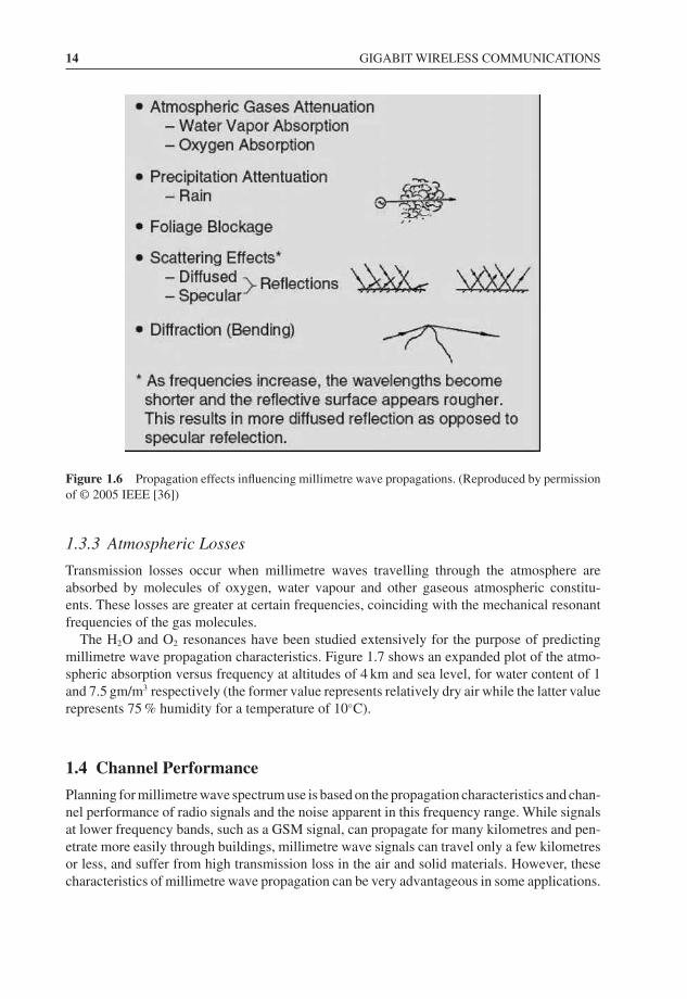
In microwave systems, transmission loss is accounted for principally by the free space loss.However, in the millimetrewave bands additional (absorption) loss factors come into play,such as gaseous losses and rain (or other micrometeors) in the transmission medium. Factorsthat affect millimetre wave propagation are given in Figure 1.6.
14 GIGABIT WIRELESS COMMUNICATIONS
Figure 1.6 Propagation effects influencing millimetre wave propagations. (Reproduced by permissionof © 2005 IEEE [36])
1.3.3 Atmospheric Losses
Transmission losses occur when millimetre waves travelling through the atmosphere areabsorbed by molecules of oxygen, water vapour and other gaseous atmospheric constitu-ents. These losses are greater at certain frequencies, coinciding with the mechanical resonantfrequencies of the gas molecules.
The H2O and O2 resonances have been studied extensively for the purpose of predictingmillimetre wave propagation characteristics. Figure 1.7 shows an expanded plot of the atmo-spheric absorption versus frequency at altitudes of 4 km and sea level, for water content of 1and 7.5 gm/m3 respectively (the former value represents relatively dry air while the latter valuerepresents 75 % humidity for a temperature of 10◦C).
1.4 Channel Performance
Planning for millimetre wave spectrum use is based on the propagation characteristics and chan-nel performance of radio signals and the noise apparent in this frequency range. While signalsat lower frequency bands, such as a GSM signal, can propagate for many kilometres and pen-etrate more easily through buildings, millimetre wave signals can travel only a few kilometresor less, and suffer from high transmission loss in the air and solid materials. However, thesecharacteristics of millimetre wave propagation can be very advantageous in some applications.