“antennas and beamformer architectures for army...
TRANSCRIPT
“Antennas and BeamformerArchitectures for Army Platforms
Steven J. Weiss
US Army Research Laboratory,Adelphi, MD 20783, USA
IEEE APS Washington ChapterWashington, DC
July 20, 2011
• Introduction, military needs for antennas
• Some practical uses for metamaterials
• Some funded work• Placement insensitivity• Mitigate loading effects
Outline
UNCLASSIFIED – APPROVED FOR PUBLIC RELEASE
• Mitigate loading effects• Realized gain enhancement
• Metamaterial-driven lens optics
• Bandwidth/gain improvements
• Conclusions
Approved for public release; distribution unlimited.2

PROBLEM
• Antennas always seem to cause problems
– Obscure LOS
– Need installing / removal / Tuning (Tweaking)
– Get damaged or break
• Everyone wants conformal Antennas
– Platforms (UAVs, Vehicles, Ships)
– Soldier (Helmet Antennas, Body Antennas)
• Present Conformal types
– Mostly resonant antennas
– Microstrip Patch Antennas / Arrays
– Meander Ant. / Arrays (Dist. Resonant), Etc.
– Fewer with good impulse response even in-band
PERFORMANCE LIMITS
• Too Thick with needed reflective backplane
– Typically need ~1/4 wavelength standoff
– Adding dielectric makes it heavy & expensive
• Narrow Band
– Rarely > few % relative bandwidth
• Limited FOV
– Resonant currents determine pattern
– Pattern nominally perpendicular to surface
• Suboptimal Arrays
– Element spacing > Lambda/2 (grating lobes)
Military Needs: Low-Profile, WidebandAntennas for Radio and other Systems
UNCLASSIFIED – APPROVED FOR PUBLIC RELEASE
– Fewer with good impulse response even in-band
CAUSE OF LIMITS
• Backplane reflector needed to prevent unwanted radiation inundesired directions
• Absorber can sometimes be used, but with undesirableconsequences
• Thickness, Weight, Cost, Ruggedness, etc.
• Surface waves can form & radiate elsewhere
• Backplane reflector causes most of the problems andperformance limits:
• Causes need for 1/4 wave standoff (thickness)
• Limits Bandwidth because of same
• Carries currents that changes pattern
SOLUTION APPROACH
• Need to eliminate Backplane Reflector
• Replace with Artificial Magnetic Conductor (AMC)
• Reflection undergoes no phase shift upon reflection
• Antenna can be placed very close to AMC
• Antenna and AMC then still both in phase
• AMC eliminates backward radiation just like reflectivebackplane.
Approved for public release; distribution unlimited.
3

• Introduction, military needs for antennas
• Some practical uses for metamaterials
• Some funded work• Placement insensitivity• Mitigate loading effects
Outline
UNCLASSIFIED – APPROVED FOR PUBLIC RELEASE
• Mitigate loading effects• Realized gain enhancement
• Metamaterial-driven lens optics
• Bandwidth/gain improvements
• Conclusions
Approved for public release; distribution unlimited.4

• Metamaterials present themselves as an additional “tool set” for designing andenhancing conformal antenna performance
– Metamaterial magnetic ground planes can reduce planar antenna sizes
• Applicable to conformal platform applications
– Metamaterials can be used to impedance match embedded antennas inplatforms - improving bandwidth
– Metamaterials can be used to reduce mutual coupling between antennasoperating at different frequencies
Electrically Small Antennas andMetamaterials
UNCLASSIFIED – APPROVED FOR PUBLIC RELEASE
operating at different frequencies
• Mitigate co-site interference
• Improve array performance
• Additional comments: For practical Army needs, metamaterials could:
– Bring electrically small antennas closer to Chu’s limit for bandwidth. Non-Foster matching excluded.
– Help to create aperture efficiencies close to 100%.
– Reduce the size of the antenna, bearing in mind that the “size” of theantenna must include the real estate of the entire metamaterial/antennastructure.
Approved for public release; distribution unlimited.5
• Introduction, military needs for antennas
• Some practical uses for metamaterials
• Some funded work• Placement insensitivity• Mitigate loading effects
Outline
UNCLASSIFIED – APPROVED FOR PUBLIC RELEASE
• Mitigate loading effects• Realized gain enhancement
• Metamaterial-driven lens optics
• Bandwidth/gain improvements
• Conclusions
Approved for public release; distribution unlimited.6
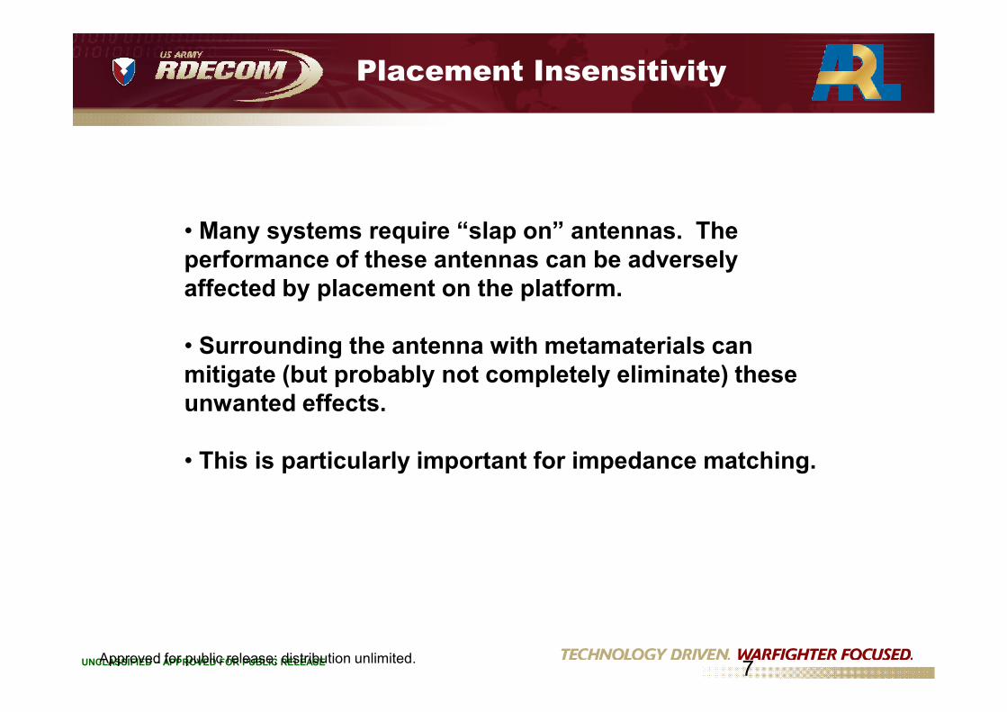
Placement Insensitivity
• Many systems require “slap on” antennas. Theperformance of these antennas can be adverselyaffected by placement on the platform.
• Surrounding the antenna with metamaterials can
UNCLASSIFIED – APPROVED FOR PUBLIC RELEASEApproved for public release; distribution unlimited.7
• Surrounding the antenna with metamaterials canmitigate (but probably not completely eliminate) theseunwanted effects.
• This is particularly important for impedance matching.

Placement issues
Goal: Employ smaller size (metamaterial) antennas based on slowwave modes to suppress detuning & reduce platform effects
CascadedUnit Cells to
Form Antenna
w
wLoop
wDBE
wMPC
Min
iatu
riza
tion
NarrowBandwidth
BroadBandwidth
Loop DBE MPC
w
wLoop
wDBE
wMPC
Min
iatu
riza
tion
NarrowBandwidth
BroadBandwidth
Loop DBE MPC
Mode Control andDispersion Engineering
Small ferriteinserts
MIN
IAT
UR
IZA
TIO
N
UNCLASSIFIED – APPROVED FOR PUBLIC RELEASEApproved for public release; distribution unlimited.8
K0 p 2p K0 p 2p
Dispersion Engineeringinserts
increasebandwidth
& enable tuningNew slot-based/recessed MPC antenna is much less immune to detuning
UNCLASSIFIED – APPROVED FOR PUBLIC RELEASE

Mitigation of Loading Effects
• An antenna placed on dielectric material (e.g., a patch antenna) willlose bandwidth due to the interaction with dielectric material.• Such considerations have important implications for integration ofantennas onto Army platforms.• Surrounding the antenna with metamaterials (actually, placing themetamaterials underneath the patch) can mitigate (but probably notcompletely eliminate) these unwanted effects.• The University of Michigan has shown that the “lost bandwidth” can be
UNCLASSIFIED – APPROVED FOR PUBLIC RELEASE
CERDEC/University of Michigan
Approved for public release; distribution unlimited.9
• The University of Michigan has shown that the “lost bandwidth” can berecovered by placement of a planar metamaterial surface just below thepatch.

Improvement in Realized Gain
Directivity:
(Parameter quantifying beam shaping - usually constrained
by aperture size)
Gain: 0 1
(takes into account the antenna's internal losses)
o
o cd o cd
D
G D ε
UNCLASSIFIED – APPROVED FOR PUBLIC RELEASE 10
(takes into account the antenna's internal losses)
Realized gain: (1oG 2
)
(takes into account the impedance match to a transmission line)
Metamaterials can help all three, but the best improvements we have seen
are with respect to measured improvements in realized gain
cd oD
.
• Introduction, military needs for antennas
• Some practical uses for metamaterials
• Some funded work• Placement insensitivity• Mitigate loading effects
Outline
UNCLASSIFIED – APPROVED FOR PUBLIC RELEASE
• Mitigate loading effects• Realized gain enhancement
• Metamaterial-driven lens optics
• Bandwidth/gain improvements
• Conclusions
Approved for public release; distribution unlimited.11

A Metamaterial-Loaded Rotman Lens
VirtualBeam Array
Physical SizeSize Reduction
Metamaterial
UNCLASSIFIED – APPROVED FOR PUBLIC RELEASE
NRI Medium
Beam ArrayReceive
Array
Metamaterial
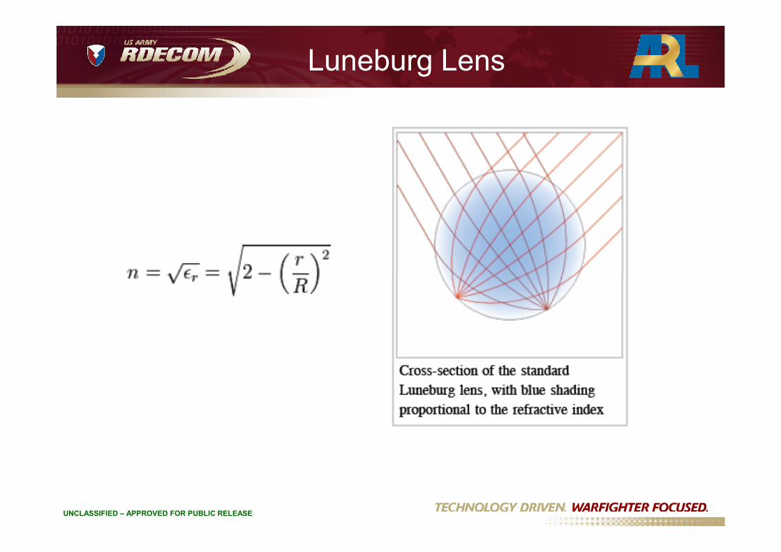
Luneburg Lens
UNCLASSIFIED – APPROVED FOR PUBLIC RELEASE
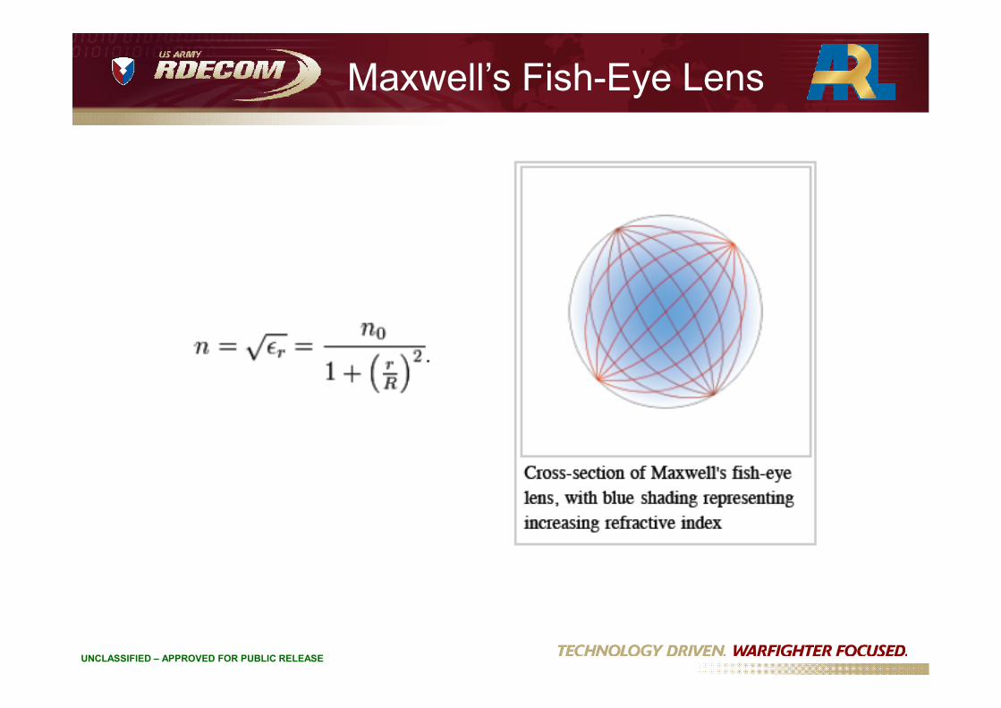
Maxwell’s Fish-Eye Lens
UNCLASSIFIED – APPROVED FOR PUBLIC RELEASE
Metamaterial-Driven Luneburg Lens
• Replace the progressively increasing or decreasing positivepermittivity layers in the lens with negative permittivity materials
• Rays will continue to bend in symmetric manner
• Resulting beam will depend on the progression of negative
UNCLASSIFIED – APPROVED FOR PUBLIC RELEASE
• Resulting beam will depend on the progression of negativepermittivity in the lens, i.e. relationship of n and radius r
• Isotropic radiators or formed beams may be produced from a feedhorn in front of lens with the right refractive index function
• Details and possible designs are underway

• Introduction, military needs for antennas
• Some practical uses for metamaterials
• Some funded work• Placement insensitivity• Mitigate loading effects
Outline
UNCLASSIFIED – APPROVED FOR PUBLIC RELEASE
• Mitigate loading effects• Realized gain enhancement
• Metamaterial-driven lens optics
• Bandwidth/gain improvements
• Conclusions
16

Low-Profile, Wideband Antennas
Wide-Banding of AMC It is well known that increasing the permeabilityof EBG structures can help increase the bandwidthof an antenna.
UNCLASSIFIED – APPROVED FOR PUBLIC RELEASE
Enhanced Bandwidth Artificial Magnetic Ground Plane for Low-Profile Antennas, Yousefi, L.; Mohajer-Iravani, B.;Ramahi, O. M., Antennas and Wireless Propagation Letters, Volume 6, Issue , 2007 Page(s):289 – 292.
17

AMC Using Electromagnetic Band Gap Surface –Possible Bandwidth Improvements
• Spiral antennas use the entire spiral at lower frequencies and less of the structureAs the frequency of operation increases – essentially keeping the aperture sizeconstant. This accounts for a reasonably stable gain over a wide bandwidth.• Metamaterial “unit cells” can be made progressively smaller in with respect to thisfact to enhance spiral antenna performance.
UNCLASSIFIED – APPROVED FOR PUBLIC RELEASE 18
Progressive EBGBroad-Band EBG
Uniform EBGNarrow-Band EBG
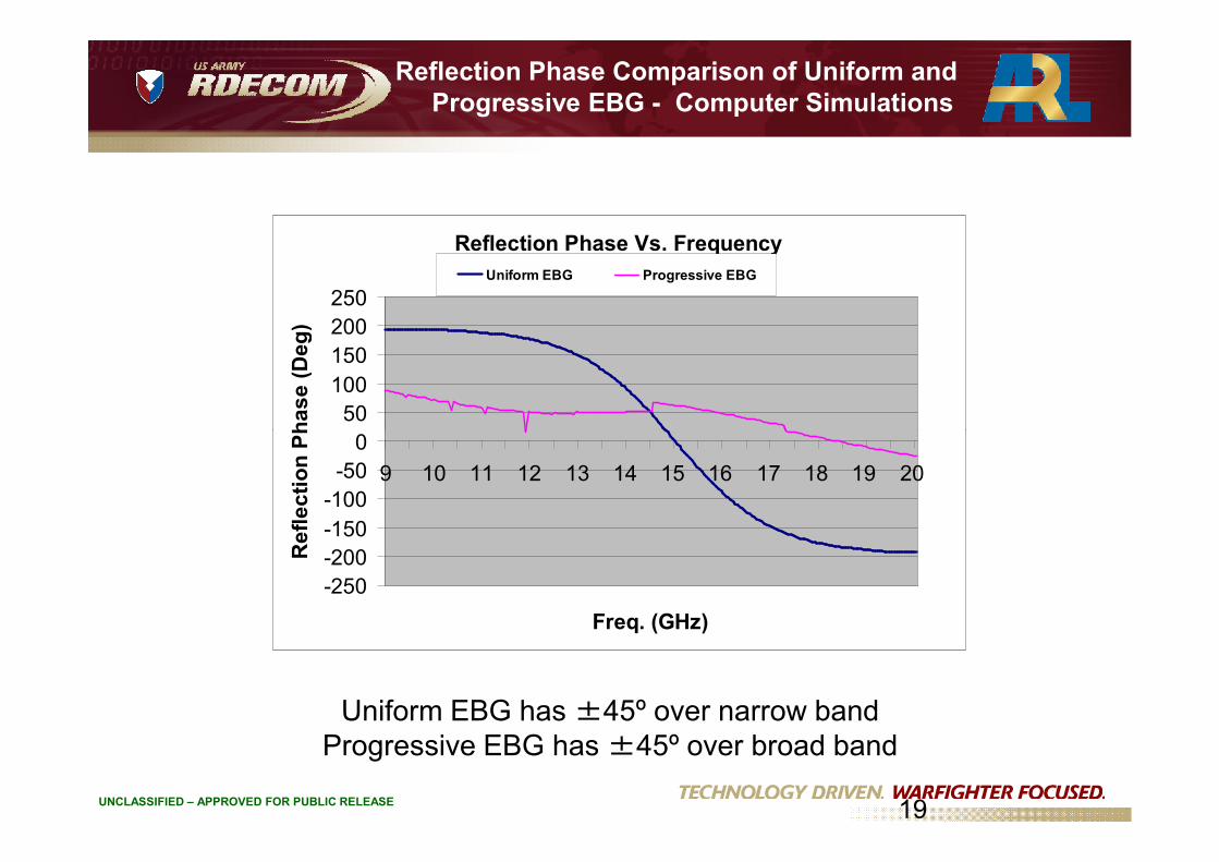
Reflection Phase Comparison of Uniform andProgressive EBG - Computer Simulations
Reflection Phase Vs. Frequency
0
50
100
150
200
250R
efl
ec
tio
nP
ha
se
(Deg
)
Uniform EBG Progressive EBG
UNCLASSIFIED – APPROVED FOR PUBLIC RELEASE
Uniform EBG has ±45º over narrow bandProgressive EBG has ±45º over broad band
-250
-200
-150
-100
-50
0
9 10 11 12 13 14 15 16 17 18 19 20
Freq. (GHz)
Re
fle
cti
on
Ph
as
e(D
eg
)
19

Random-Oriented, Random-SpacedNegative Refractive Index Metamaterial
UNCLASSIFIED – APPROVED FOR PUBLIC RELEASE
• Unit cell is a Capacitively Loaded Loop + Probe (CLL-P)• Isotropic• Uniform negative refractive index at wide inclined angles• Wide-band operation• Fabrication and measurements under way
Basic Unit CellRandomly-Oriented, Randomly-Spaced

A High-Gain Antenna
With layered media, it is possible to achieve a high-gain configuration.This antenna was fabricated to measure the predicted simulations.
Incorrect“Chu Sphere”
UNCLASSIFIED – APPROVED FOR PUBLIC RELEASE
21
1. David R. Jackson, and Nicolaos G. Alexopoulos, “Gain EnhancementMethods for Printed Circuit Antennas,” IEEE Transactions on Antennasand Propagation, Vol. AP-33, pp. 976-987, September 1985.
Ground Plane

Measurements of the High-gain Antenna
• The antenna was fabricated and the high-gain was measured.• A remarkable 16 dBi for a “dipole.”
UNCLASSIFIED – APPROVED FOR PUBLIC RELEASE
22

Aperture Size – An Important Consideration
• A study was performed decreasing the radius of the structure• The 16 dBi gain remained fairly constant, but occurred at higher and
higher frequencies as the structure became smaller and smaller.• The structure was acting like a cavity resonator with predictable modes.
UNCLASSIFIED – APPROVED FOR PUBLIC RELEASE
23

Comments on “Supergain”
UNCLASSIFIED – APPROVED FOR PUBLIC RELEASE
Henry Jasic , “Antenna Engineering Handbook,” McGraw Hill, 1961.
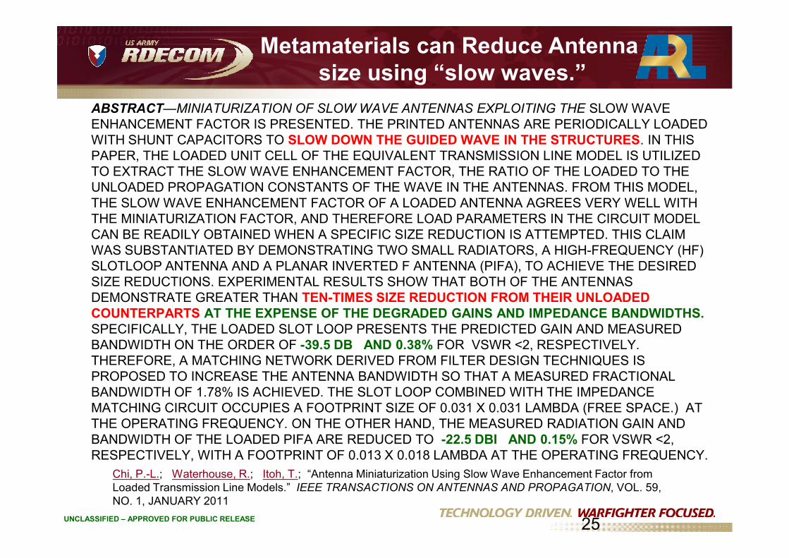
ABSTRACT—MINIATURIZATION OF SLOW WAVE ANTENNAS EXPLOITING THE SLOW WAVEENHANCEMENT FACTOR IS PRESENTED. THE PRINTED ANTENNAS ARE PERIODICALLY LOADEDWITH SHUNT CAPACITORS TO SLOW DOWN THE GUIDED WAVE IN THE STRUCTURES. IN THISPAPER, THE LOADED UNIT CELL OF THE EQUIVALENT TRANSMISSION LINE MODEL IS UTILIZEDTO EXTRACT THE SLOW WAVE ENHANCEMENT FACTOR, THE RATIO OF THE LOADED TO THEUNLOADED PROPAGATION CONSTANTS OF THE WAVE IN THE ANTENNAS. FROM THIS MODEL,THE SLOW WAVE ENHANCEMENT FACTOR OF A LOADED ANTENNA AGREES VERY WELL WITHTHE MINIATURIZATION FACTOR, AND THEREFORE LOAD PARAMETERS IN THE CIRCUIT MODELCAN BE READILY OBTAINED WHEN A SPECIFIC SIZE REDUCTION IS ATTEMPTED. THIS CLAIMWAS SUBSTANTIATED BY DEMONSTRATING TWO SMALL RADIATORS, A HIGH-FREQUENCY (HF)SLOTLOOP ANTENNA AND A PLANAR INVERTED F ANTENNA (PIFA), TO ACHIEVE THE DESIREDSIZE REDUCTIONS. EXPERIMENTAL RESULTS SHOW THAT BOTH OF THE ANTENNAS
Metamaterials can Reduce Antennasize using “slow waves.”
UNCLASSIFIED – APPROVED FOR PUBLIC RELEASE
SIZE REDUCTIONS. EXPERIMENTAL RESULTS SHOW THAT BOTH OF THE ANTENNASDEMONSTRATE GREATER THAN TEN-TIMES SIZE REDUCTION FROM THEIR UNLOADEDCOUNTERPARTS AT THE EXPENSE OF THE DEGRADED GAINS AND IMPEDANCE BANDWIDTHS.SPECIFICALLY, THE LOADED SLOT LOOP PRESENTS THE PREDICTED GAIN AND MEASUREDBANDWIDTH ON THE ORDER OF -39.5 DB AND 0.38% FOR VSWR <2, RESPECTIVELY.THEREFORE, A MATCHING NETWORK DERIVED FROM FILTER DESIGN TECHNIQUES ISPROPOSED TO INCREASE THE ANTENNA BANDWIDTH SO THAT A MEASURED FRACTIONALBANDWIDTH OF 1.78% IS ACHIEVED. THE SLOT LOOP COMBINED WITH THE IMPEDANCEMATCHING CIRCUIT OCCUPIES A FOOTPRINT SIZE OF 0.031 X 0.031 LAMBDA (FREE SPACE.) ATTHE OPERATING FREQUENCY. ON THE OTHER HAND, THE MEASURED RADIATION GAIN ANDBANDWIDTH OF THE LOADED PIFA ARE REDUCED TO -22.5 DBI AND 0.15% FOR VSWR <2,RESPECTIVELY, WITH A FOOTPRINT OF 0.013 X 0.018 LAMBDA AT THE OPERATING FREQUENCY.
Chi, P.-L.; Waterhouse, R.; Itoh, T.; “Antenna Miniaturization Using Slow Wave Enhancement Factor fromLoaded Transmission Line Models.” IEEE TRANSACTIONS ON ANTENNAS AND PROPAGATION, VOL. 59,NO. 1, JANUARY 2011
25

Conclusions For Metamaterials
• Metamaterial present exciting possibilities for enhanced antennaperformance.
• This is particularly true for in-situ antenna performance.
• Electrically small antennas will always have limitations with respect toaperture size and the Chu limit, but improvements in realized gain havebeen shown.
UNCLASSIFIED – APPROVED FOR PUBLIC RELEASE
been shown.
• Innovative ideas for enhancement classical of wideband antennastructures (e.g., the spiral antenna) can further extend the operationalbandwidth of the antenna.
• Military application where the antennas are closely located to each otheron platforms require innovative strategies to de-conflict operationalproblems. Metamaterials offer possible solutions.
26
Beamformers
Next, we describe ARL efforts to realize antenna array beamformersfor Army platforms – with particular attention to the RotmanLens. Considerations such as size, weight, cost, and performanceare examined for a number of different case studies. First, aconformal Rotman lens array for terrestrial communicationapplications is described. Next, a X-band antenna array, presentlyunder development for a compact radar, will be introduced and
UNCLASSIFIED – APPROVED FOR PUBLIC RELEASE
under development for a compact radar, will be introduced andanalyzed. A Satellite On the Move (SOTM) demonstrator array (Ka-band) that achieves scanning through the use of MEMs phaseshifters will be presented as will a Ka-band Rotman lens -developed to demonstrate the Multi-Function RF concept. Finally, a75 GHz beamformer for use in collision avoidance will be examined.
Outline
• Rotman Lens – An ARL legacy
• A flexible Rotman lens for TerrestrialCommunications
• A Satellite on the Move (SOTM) array
UNCLASSIFIED – APPROVED FOR PUBLIC RELEASE
• A Satellite on the Move (SOTM) arraywith MEMs phase shifters
• A 76 GHz array for collisionavoidance applications
• Conclusion
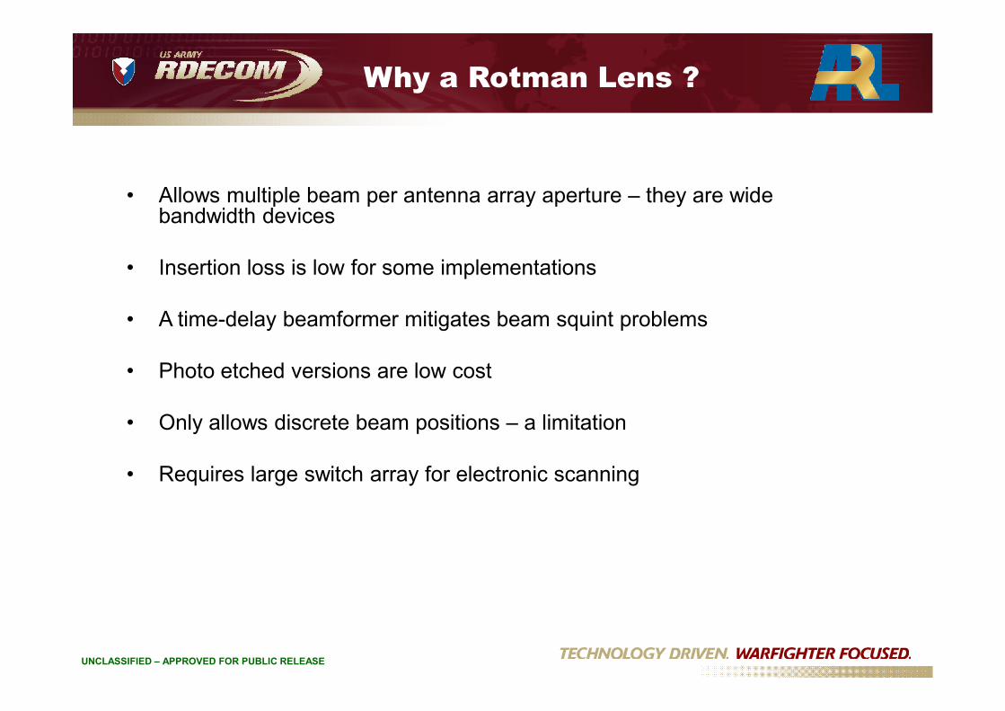
Why a Rotman Lens ?
• Allows multiple beam per antenna array aperture – they are widebandwidth devices
• Insertion loss is low for some implementations
• A time-delay beamformer mitigates beam squint problems
UNCLASSIFIED – APPROVED FOR PUBLIC RELEASE
• Photo etched versions are low cost
• Only allows discrete beam positions – a limitation
• Requires large switch array for electronic scanning

Rotman Lens in MFRF Architecture
Transmit Array (TX)with Power MMICs
Transmit Rotman
UNCLASSIFIED – APPROVED FOR PUBLIC RELEASE
2x16 TXSwitchMatrix
2x16 RXSwitchMatrix
Receive RotmanReceive Array (RX)with LNA MMICs
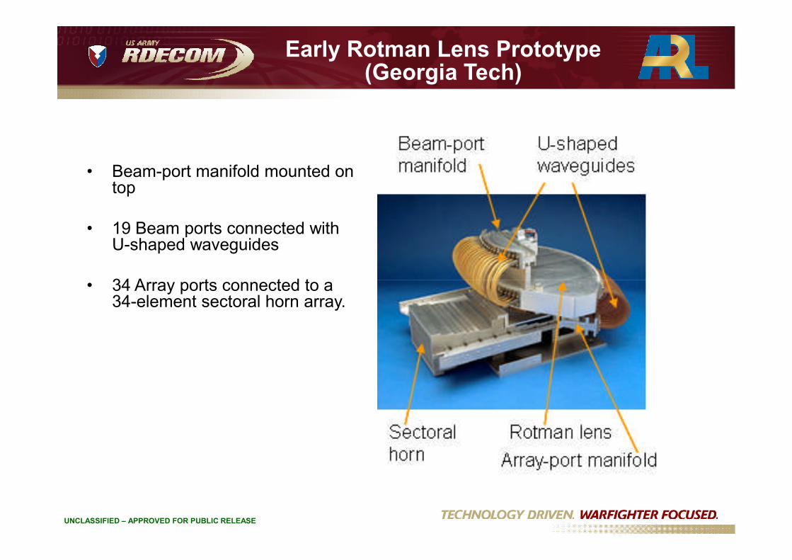
• Beam-port manifold mounted ontop
• 19 Beam ports connected withU-shaped waveguides
• 34 Array ports connected to a
Early Rotman Lens Prototype(Georgia Tech)
UNCLASSIFIED – APPROVED FOR PUBLIC RELEASE
• 34 Array ports connected to a34-element sectoral horn array.

Aluminum Rotman Lens
UNCLASSIFIED – APPROVED FOR PUBLIC RELEASE
Fabrication tolerances: +/- 0.003” side-to-side+/- 0.005” top-to-bottom

Plastic Rotman Lens withConductive Plating
Machining performed at ARL, Adelphi Metallization performed under contract to WMRD
UNCLASSIFIED – APPROVED FOR PUBLIC RELEASE
Rotman lens machined in Ultem 1000. After metallization with gold as the final layer.
Aluminum: 14.65 poundsUltem: 6.05 pounds60% Weight Reduction

Aluminum Rotman Lens
UNCLASSIFIED – APPROVED FOR PUBLIC RELEASE
Plastic Rotman Lens
UNCLASSIFIED – APPROVED FOR PUBLIC RELEASE

Why the Improvement?
Aluminum Machining Plastic Machining
Metal Plating
UNCLASSIFIED – APPROVED FOR PUBLIC RELEASE
- Plating causes small build-up at machined edgespossibly increasing performance due to better waveguiderealization when both halves are pressed together
VERY EXAGGERATED
Metal Plating

Microstrip Rotman Lens
Measured Gain ~ 12dBi
UNCLASSIFIED – APPROVED FOR PUBLIC RELEASE
Measured Insertionloss ~ 9.5 dB
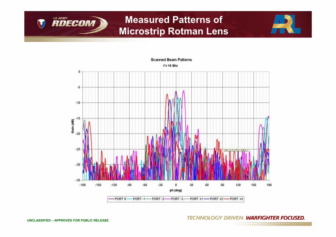
Measured Patterns ofMicrostrip Rotman Lens
UNCLASSIFIED – APPROVED FOR PUBLIC RELEASE

Rotman Lens SoftwareDevelopment - Ansoft Effort
• Collaboration with Ohio State University
• Hybridize HFSS FEM code with DomainDecomposition Method (DDM)
UNCLASSIFIED – APPROVED FOR PUBLIC RELEASE

Rotman Lens Software Development -Remcom Effort
UNCLASSIFIED – APPROVED FOR PUBLIC RELEASE
• Hybridize XFDTD code with ray tracing techniques (GO, UTD)
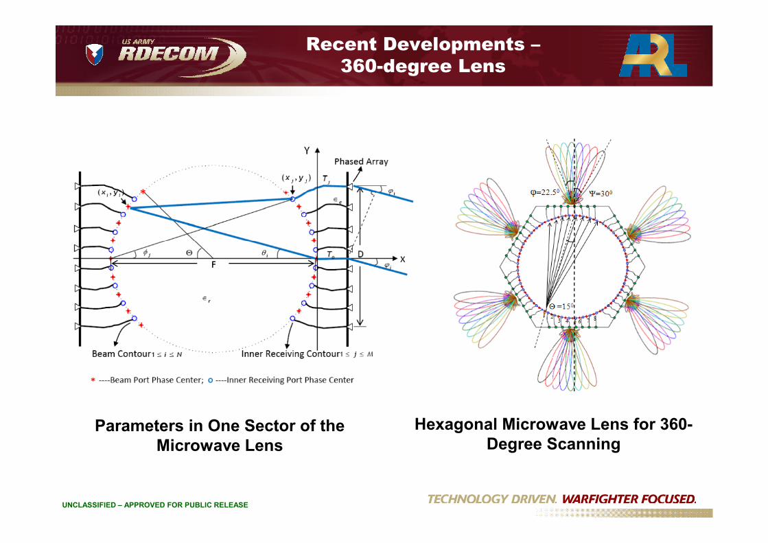
Recent Developments –360-degree Lens
UNCLASSIFIED – APPROVED FOR PUBLIC RELEASE
Hexagonal Microwave Lens for 360-Degree Scanning
Parameters in One Sector of theMicrowave Lens

Beamformer Outline
• Rotman Lens – An ARL legacy
• A flexible Rotman lens forTerrestrial Communications
• A 76 GHz array for collision
UNCLASSIFIED – APPROVED FOR PUBLIC RELEASE
• A 76 GHz array for collisionavoidance applications
• Conclusion

Integrated Microstrip RotmanLens/Array
UNCLASSIFIED – APPROVED FOR PUBLIC RELEASE
Modular (left) and Integrated Rotman Lens/Array
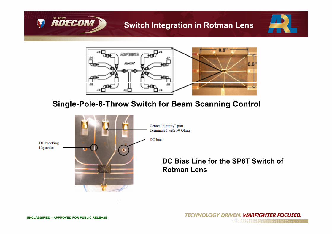
Switch Integration in Rotman Lens
Single-Pole-8-Throw Switch for Beam Scanning Control
UNCLASSIFIED – APPROVED FOR PUBLIC RELEASE
DC Bias Line for the SP8T Switch ofRotman Lens

Measured Radiation Pattern forIntegrated Lens/Array
UNCLASSIFIED – APPROVED FOR PUBLIC RELEASE
Comparison of Rotman Lens Integrated without Switches (left), &Integrated
with Switches (right)

Refractive Focusing UsingNegative-Refractive-Index Metamaterials
Objectives
• Show through simulation and measurements focusing using NRI metamaterials• Use metamaterials for size reduction of large electromagnetic structures
UNCLASSIFIED – APPROVED FOR PUBLIC RELEASE
ReceiveArray
Source
NRI Medium
1 2
3
4
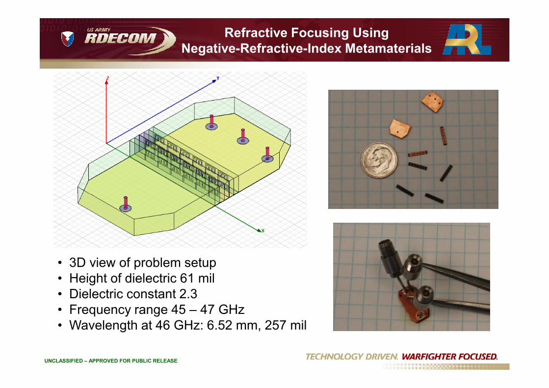
Refractive Focusing UsingNegative-Refractive-Index Metamaterials
UNCLASSIFIED – APPROVED FOR PUBLIC RELEASE
• 3D view of problem setup• Height of dielectric 61 mil• Dielectric constant 2.3• Frequency range 45 – 47 GHz• Wavelength at 46 GHz: 6.52 mm, 257 mil

Refractive Focusing UsingNegative-Refractive-Index Metamaterials
dB
-30.0
-25.0
-20.0
-15.0
-10.0
-5.0
S11
S31
S21
dB
-25.0
-20.0
-15.0
-10.0
-5.0
S11
S31
S21
UNCLASSIFIED – APPROVED FOR PUBLIC RELEASE
Frequency, GHz
45.0 45.5 46.0 46.5 47.0-35.0
-30.0
Simulated S-Parameterswithout Metamaterial
Frequency, GHz
45.0 45.5 46.0 46.5 47.0-30.0
-25.0
Simulated S-Parameterswith Metamaterial

Refractive Focusing UsingNegative-Refractive-Index Metamaterials
S11 blue, S21 red, S31 green, S21w/o mm black
-15
-10
-5
Retu
rn/I
nsert
ion
Lo
ss,
dB
UNCLASSIFIED – APPROVED FOR PUBLIC RELEASE
-20
45 46 47
Frequency, GHz
Retu
rn/I
nsert
ion
Lo
ss,
dB
S11 with metamaterialS21 with metamaterialS31 with metamaterialS21 without metamaterial
Measured S-Parameters
Outline
• Rotman Lens – An ARL legacy
• A flexible Rotman lens for TerrestrialCommunications
• A 76 GHz array for collision
UNCLASSIFIED – APPROVED FOR PUBLIC RELEASE
• A 76 GHz array for collisionavoidance applications
• Conclusion

Requirements
16
-wa
ysw
itch
Radar
RX
16
-wa
ysw
itch
16
-wa
ysw
itch
Radar
RX
UNCLASSIFIED – APPROVED FOR PUBLIC RELEASE
- Low profile
- 16 narrow beams in azimuth switchable at fastrate in nanoseconds range
- Broad beam in elevation
TXTX

Antenna for Collision Avoidance
- Optimized horn array- Horn dimensions: 1.3λ in the H-plane (array plane) and 2.0λ in the E-plane- Overall aperture size: 0.5” (height) X 7.0”(width) X 5.0” (depth)- Position on vehicle depends oncoverage requirements
Multiple Array Concept
UNCLASSIFIED – APPROVED FOR PUBLIC RELEASE
1.8o
32o
Pyramidal Horn Array
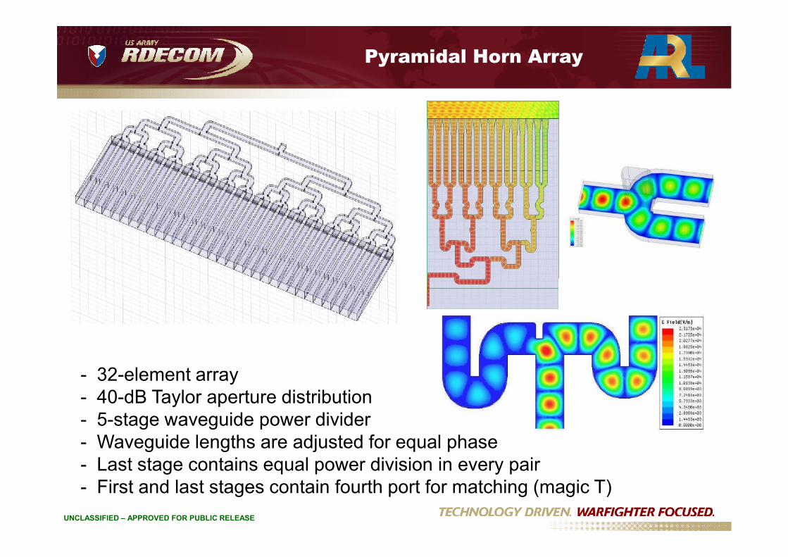
UNCLASSIFIED – APPROVED FOR PUBLIC RELEASE
- 32-element array- 40-dB Taylor aperture distribution- 5-stage waveguide power divider- Waveguide lengths are adjusted for equal phase- Last stage contains equal power division in every pair- First and last stages contain fourth port for matching (magic T)

Fabricated Array
UNCLASSIFIED – APPROVED FOR PUBLIC RELEASE
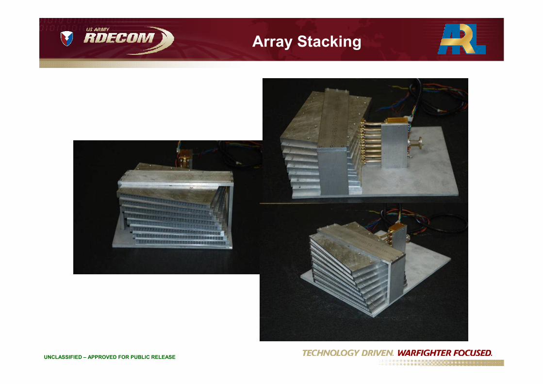
Array Stacking
UNCLASSIFIED – APPROVED FOR PUBLIC RELEASE
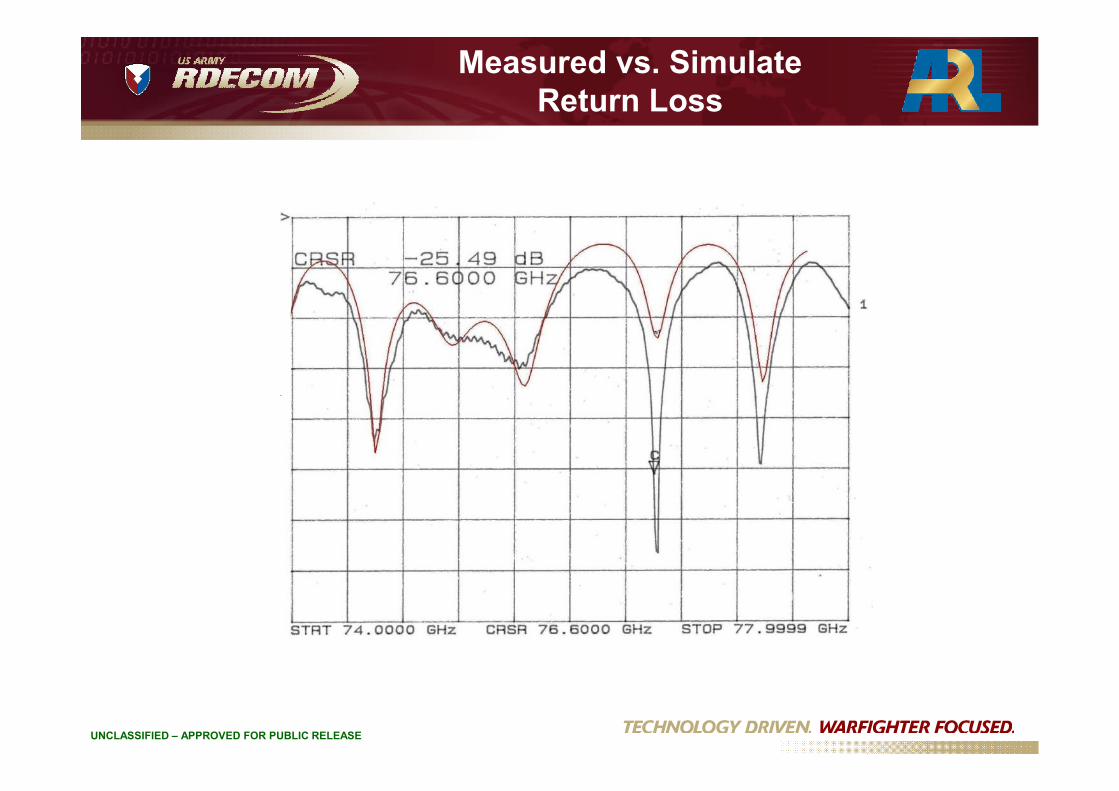
Measured vs. SimulateReturn Loss
UNCLASSIFIED – APPROVED FOR PUBLIC RELEASE

Measured vs. Simulated Patterns
-30
-27
-24
-21
-18
-15
-12
-9
-6
-3
0
UNCLASSIFIED – APPROVED FOR PUBLIC RELEASE
-66
-63
-60
-57
-54
-51
-48
-45
-42
-39
-36
-33
-30
-20 -18 -16 -14 -12 -10 -8 -6 -4 -2 0 2 4 6 8 10 12 14 16 18 20
A ng le ( D egrees)
HFSS
Measured

Measured Patterns atDifferent Frequencies
-20
-10
0
10
20
30
76.3GHz
76.6GHz
UNCLASSIFIED – APPROVED FOR PUBLIC RELEASE
-70
-60
-50
-40
-30
-20
-90 -75 -60 -45 -30 -15 0 15 30 45 60 75 90
76.6GHz
78.0GHz
Outline
• Rotman Lens – An ARL legacy
• A flexible Rotman lens for TerrestrialCommunications
• A 76 GHz array for collision
UNCLASSIFIED – APPROVED FOR PUBLIC RELEASE
• A 76 GHz array for collisionavoidance applications
• Conclusion
Conclusions
• Antenna development for military applicationsis a collaborative process that involves DoDlabs, universities and industry
• Antenna has to be designed with platform and
UNCLASSIFIED – APPROVED FOR PUBLIC RELEASE
• Antenna has to be designed with platform andenvironment in mind
• In-situ antenna design & analysis are essentialto successful development
Conclusions
• New simulation tools are still needed for newfrontiers, such as metamaterials and nano-designs
• Fully integrated, adaptive designs have beenat the forefront of antenna research and
UNCLASSIFIED – APPROVED FOR PUBLIC RELEASE
at the forefront of antenna research anddevelopment
• Wideband, low profile, high efficiency,polarization diversity and low cost are stillrequirements