antenna solutions and ... - assets.sennheiser.com · the illustration indicates which sma and r-sma...
TRANSCRIPT

ANTENNA SOLUTIONS AND RECOMMENDATIONS ON
ANTENNA MOUNTING
SpeechLine Digital Wireless
SPEECHLINE DIGITAL WIRELESSAN 1106 v1.1
SpeechLine antenna solutions and recommendations on antenna mounting

SpeechLine Digital Wireless / ANTENNA SOLUTIONS / AN 1106 v1.1 | 2
Antenna solutions for SpeechLine Digital WirelessThis document gives an overview over several possibilities of mounting and using antennas for a SpeechLine Digital Wireless system. Furthermore, this document provides recommendations on several aspects which should be considered for the different antenna solutions.
Antenna setup planning for SpeechLine Digital WirelessWhen planning the installation of SpeechLine Digital Wireless devices and antennas for each room, observe the following guidelines:
Mount all SpeechLine Digital Wireless receivers of one room together in one rack. Make sure to have a direct line of sight between the transmitters and the receiving antennas. Depending on the room characteristics there are several options how to install the receiving antennas. We recommend the following options in this order:• Option 1: remotely mounted using the AWM 2 for one receiver or AWM 4 for two receivers• Option 2: remotely mounted using the AWM 2 or AWM 4 with multiple receivers combined (passive combiner)• Option 3: mounted in a rack (front)• Option 4: mounted in a rack (rear)
When mounting antennas remotely, observe the minimum distance to possibly existing DECT access points and also take into account the cable lengths.
Always switch all receivers on and off with a common power supply (e.g. a multi-outlet power strip with a central on/off switch) in order to achieve the best performance of a system.
For further technical details and recommendations on the four options please refer to the chapter Antenna moun-ting options starting on the next page.
Mounting instructions for the AWM 2When using the AWM 2 please observe the following mounting instructions.
min
. 16
0 m
m
3/8"

SpeechLine Digital Wireless / ANTENNA SOLUTIONS / AN 1106 v1.1 | 3
As mentioned above, there are multiple possibilities for remote mounting the anntennas. In the following, we will explain the most common options with additional recommendations in order of preference.
Option 1: Connecting the AWM 2/AWM 4 directly to the receiver(s)You can connect one SL Rack Receiver DW unit directly to one Sennheiser AWM 2 and you can connect two SL Rack Receiver DW units directly to one Sennheiser AWM 4.
SL Rack Receiver DWSL Rack Receiver DW SL Rack Receiver DW
Link I - Ant ILink I - Ant II Link II - Ant ILink II - Ant II
AWM 4AWM 2
CL 1 PP (1 m / 3.3 ft)CL 5 PP (5 m / 16.4 ft)CL 10 PP (10 m / 32.8 ft)CL 20 PP (20 m / 65.6 ft)
CL 5 (5 m / 16.4 ft)CL 10 (10 m / 32.8 ft)CL 20 (20 m / 65.6 ft)
For the AWM 2 you can use Sennheiser CL 5/10/20 extension cables. For the AWM 4 you can use Sennheiser CL 1/5/10/20 PP extension cables. Please observe the following information concerning the use of these extension cables.
Signal loss due to extension cables
In this scenario, using extension cables for remote antenna mounting results in a loss of transmission power, depending on the cable length and type. Sennheiser offers low-loss extension cables with the CL cable types.
You can compensate this signal loss by configuring the transmission power of the SL Rack Receiver DW accodingly. Observe the following minimum transmission power settings (SL Rack Receiver DW: System Settings menu -> RF Power) for the respective cable lengths:
Cable length of 5 m -> at least Level 1 Cable length of 10 m -> selected RF Level +1, at least Level 2 Cable length of 20 m -> selected RF Level +1, at least Level 3 Cable length from 25 m onwards -> selected RF Level +2, at least Level 4
Antenna mounting options

SpeechLine Digital Wireless / ANTENNA SOLUTIONS / AN 1106 v1.1 | 4
Remote antenna distances and line of sight
If you use multiple antenna wall mounts (AWM 2/AWM 4) in one room or if individual installation and mounting of the antennas is desired, please observe the following aspects:
Position all antennas close to each other. Make sure that the distances between all antennas are all equal and the same as on the back of the receiver or on the antenna wall mount AWM 2.
If possible, group the antennas the following way:• All antennas A from sockets ANT I of the receivers in one group according to above mentioned requirements• All antennas B from sockets ANT II of the receivers in one group according to above mentioned requirements
Ant II Ant I
B
B
B
B
B
B
A
A
A
A
A
A
All antennas B from Ant II socketsof all SL Rack Receiver DW units
All antennas A from Ant I socketsof all SL Rack Receiver DW units
B B B
B B B
A A A
A A A
min. 17 cm (7")
minimum 7.5 cm (3")recommended 17 cm (7")
≤ 1 m (39")
Distance to reflecting surface / obstacle: min. 7.5 cm (3"), recommended 17 cm (7")
≤ 1
m (3
9")
If you are using several AWM 2 antenna wall mounts, make sure to keep equal distances between all antennas:
Ideally, position the antennas or the antenna wall mounts at a minimum height of 2 m with a direct line of sight (without obstacles or people) between the transmitters and the antennas.
SpeechLine Digital Wireless / ANTENNA SOLUTIONS / AN 1106 v1.1 | 5
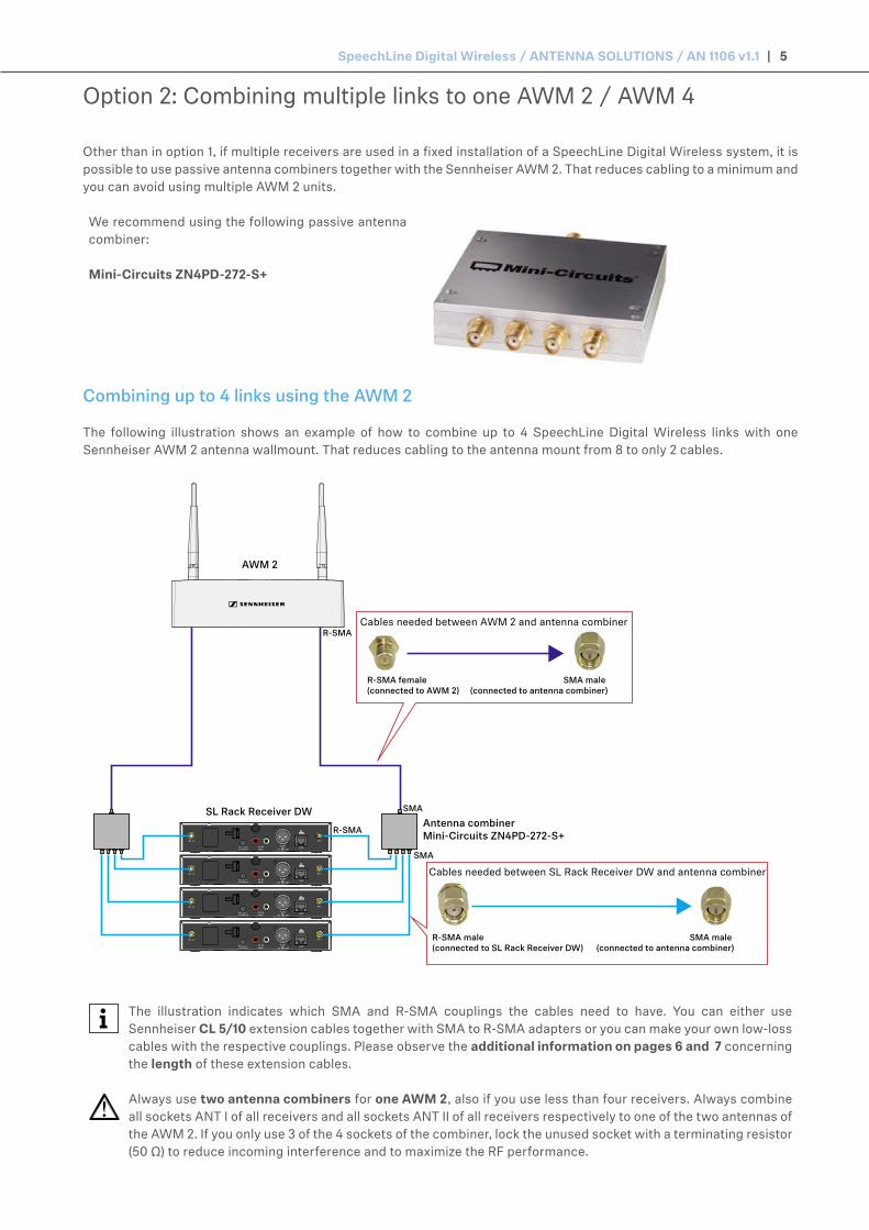
Option 2: Combining multiple links to one AWM 2 / AWM 4
Other than in option 1, if multiple receivers are used in a fixed installation of a SpeechLine Digital Wireless system, it is possible to use passive antenna combiners together with the Sennheiser AWM 2. That reduces cabling to a minimum and you can avoid using multiple AWM 2 units.
We recommend using the following passive antenna combiner:
Mini-Circuits ZN4PD-272-S+
Combining up to 4 links using the AWM 2
The following illustration shows an example of how to combine up to 4 SpeechLine Digital Wireless links with one Sennheiser AWM 2 antenna wallmount. That reduces cabling to the antenna mount from 8 to only 2 cables.
SL Rack Receiver DWAntenna combinerMini-Circuits ZN4PD-272-S+
SMA
SMA
R-SMA
R-SMA
R-SMA female (connected to AWM 2)
SMA male (connected to antenna combiner)
R-SMA male (connected to SL Rack Receiver DW)
SMA male (connected to antenna combiner)
AWM 2
Cables needed between AWM 2 and antenna combiner
Cables needed between SL Rack Receiver DW and antenna combiner
The illustration indicates which SMA and R-SMA couplings the cables need to have. You can either use Sennheiser CL 5/10 extension cables together with SMA to R-SMA adapters or you can make your own low-loss cables with the respective couplings. Please observe the additional information on pages 6 and 7 concerning the length of these extension cables.
Always use two antenna combiners for one AWM 2, also if you use less than four receivers. Always combine all sockets ANT I of all receivers and all sockets ANT II of all receivers respectively to one of the two antennas of the AWM 2. If you only use 3 of the 4 sockets of the combiner, lock the unused socket with a terminating resistor (50 Ω) to reduce incoming interference and to maximize the RF performance.

SpeechLine Digital Wireless / ANTENNA SOLUTIONS / AN 1106 v1.1 | 6
Combining up to 8 links using the AWM 4
The following illustration shows an example of how to combine up to 8 SpeechLine Digital Wireless links with one Sennheiser AWM 4 antenna wallmount. That reduces cabling to the antenna mount from 16 to only 4 cables.
SL Rack Receiver DW
Antenna combinerMini-Circuits ZN4PD-272-S+SMA
Link I - Ant ILink I - Ant II Link II - Ant ILink II - Ant II
SMA
R-SMA
R-SMA
R-SMA male (connected to AWM 4)
SMA male (connected to antenna combiner)
R-SMA male (connected to SL Rack Receiver DW)
SMA male (connected to antenna combiner)
AWM 4
Cables needed between AWM 4 and antenna combiner
Cables needed between SL Rack Receiver DW and antenna combiner
The illustration indicates which SMA and R-SMA couplings the cables need to have. You can either use Sennheiser CL 5/10 or CL 1/5/10 PP extension cables together with SMA to R-SMA adapters or you can make your own low-loss cables with the respective couplings. Please observe the additional information below concerning the length of these extension cables.
Always use four antenna combiners for one AWM 4, also if you use less than eight receivers. Always combine all sockets ANT I of up to four receivers and all sockets ANT II of up to four receivers respectively to the two sockets of one link of the AWM 4. Never use more than four antenna combiners to combine more than 16 links to one AWM 4. If you do not use all sockets of the combiner, lock the unused sockets with a terminating resistor (50 Ω) to reduce incoming interference and to maximize the RF performance.
Signal loss due to extension cables and combiners
In this scenario, using extension cables for remote antenna mounting results in a loss of transmission power, depending on the cable length and type. Sennheiser offers low-loss extension cables with the CL cable types.
You can compensate this signal loss by configuring the transmission power of the SL Rack Receiver DW accodingly. Observe the following minimum transmission power settings (SL Rack Receiver DW: System Settings menu -> RF Power) for the respective cable lengths. The antenna combiner also produces a signal loss, which is equivalent to 15 m of extension cable. This loss needs to be taken into account in order to calculate the required transmission power levels.

SpeechLine Digital Wireless / ANTENNA SOLUTIONS / AN 1106 v1.1 | 7
We recommend using the following cable lengths in combination with the antenna combiner:
receiver to combiner: 1 m -> combiner to AWM 2: 1 m receiver to combiner: 1 m -> combiner to AWM 2: 5 m receiver to combiner: 1 m -> combiner to AWM 2: 10 m receiver to combiner: 5 m -> combiner to AWM 2: 1 m receiver to combiner: 5 m -> combiner to AWM 2: 5 m receiver to combiner: 10 m -> combiner to AWM 2: 1 m
Cables longer than 10 m are not recommended for this option.
This results in the following transmission power levels to be set up in the menu of the SL Rack Receiver DW, or simultaneously for all receivers in the Sennheiser Control Cockpit software:
Cable length of 5 m plus combiner -> at least Level 2 Cable length of 10 m plus combiner -> at least Level 3
Direct line of sight
Ideally, position the antenna wall mount at a minimum height of 2 m with a direct line of sight (without obstacles or people) between the transmitters and the antennas.
Option 3: Rack mounting - frontIf you want to mount the antennas in a rack together with the receivers, we recommend mounting them to the front side of the rack using the GA 4 rack mount kit.
Always leave 1U of space between the receivers and the antennas.
Position the antennas at an angle of approximately 45°.
SpeechLine Digital Wireless / ANTENNA SOLUTIONS / AN 1106 v1.1 | 8
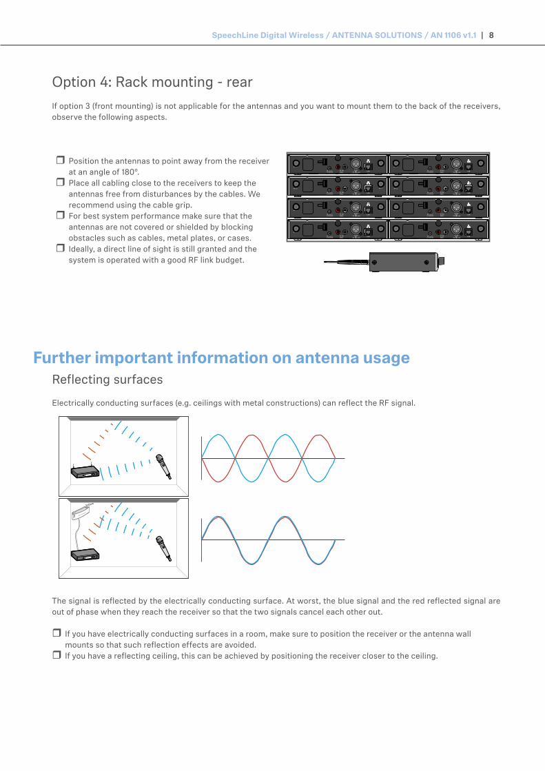
Reflecting surfaces
Electrically conducting surfaces (e.g. ceilings with metal constructions) can reflect the RF signal.
The signal is reflected by the electrically conducting surface. At worst, the blue signal and the red reflected signal are out of phase when they reach the receiver so that the two signals cancel each other out.
If you have electrically conducting surfaces in a room, make sure to position the receiver or the antenna wall mounts so that such reflection effects are avoided.
If you have a reflecting ceiling, this can be achieved by positioning the receiver closer to the ceiling.
Further important information on antenna usage
Option 4: Rack mounting - rearIf option 3 (front mounting) is not applicable for the antennas and you want to mount them to the back of the receivers, observe the following aspects.
Position the antennas to point away from the receiver at an angle of 180°.
Place all cabling close to the receivers to keep the antennas free from disturbances by the cables. We recommend using the cable grip.
For best system performance make sure that the antennas are not covered or shielded by blocking obstacles such as cables, metal plates, or cases.
Ideally, a direct line of sight is still granted and the system is operated with a good RF link budget.

SpeechLine Digital Wireless / ANTENNA SOLUTIONS / AN 1106 v1.1 | 9
Blocking effects from other transmitters
As with any other wireless microphone system, blocking may occur due to incorrectly positioned transmitters. In order to avoid any kind of blocking, please observe the following recommendations:
Place DECT phones or DECT access points at least 7 m away from the antennas. Place other wireless devices such as mobile phones at least 1-2 m away from the antennas.
When transmitters are in use, do not place other transmitters in the blocking range. If you need to place them there, switch them off.
General rule for distance of blocking range:
Blocking range Free rangeratio 1:1
Example: