antenna design - photon's eportfolio
TRANSCRIPT

Name: Shabuktagin Photon Khan UNT ID: 10900555 Instructor’s Name: Professor Hualiang Zhang Course Name: Antenna Theory and Design Course ID: EENG 5420 Email: [email protected] Department of Electrical Engineering
University of North Texas

Contents Abstract ........................................................................................................................................... 1
Technical Method ........................................................................................................................... 1
Microstrip .................................................................................................................................... 1
HyperLynx .................................................................................................................................. 2
Flow Chart of the HyperLynx ..................................................................................................... 3
The General Dimension of the Microstrip Antenna ................................................................... 3
Feeding Structures of Microstrip Antennas Equivalent Circuit .................................................. 4
Structure and Methods .................................................................................................................... 5
S-Parameter ................................................................................................................................. 7
Gain, Directivity and Radiation Efficiency .............................................................................. 14
Conclusion and Further Discussion .............................................................................................. 14
Problems Faced ......................................................................................................................... 14
Final Thoughts .......................................................................................................................... 14
References ..................................................................................................................................... 15

Abstract In this lab, LineGauge was used to design a rectangular patch microstrip antenna with a center
frequency of 2.3 GHz. The substrate is RT/Duroid 5880 which has a dielectric constant of 2.2.
The substrate thickness is 0.787 mm with a lost tangent =0.0009. At the end, S-parameter
simulation and plotting the radiation parameters of the rectangular patch was done using slots
and without slots.
Technical Method Microstrip A microstrip is a thin, flat electrical conductor separated from a ground plane by a layer of
dielectric or an air gap. The characteristic impedance (Zc) of the Microstrip-Line is determined
by “W”, “d”, and the permittivity of the substrate.
Figure 1(a): Microstrip
Microstrip is a type of electrical transmission line which can be fabricated using printed circuit
board technology, and is used to convey microwave-frequency signals. It consists of a
conducting strip separated from a ground plane by a dielectric layer known as the substrate.
Microwave components such as antennas, couplers, filters, power dividers etc. can be formed
from microstrip, the entire device existing as the pattern of metallization on the substrate.
Microstrip is thus much less expensive than traditional waveguide technology, as well as being
far lighter and more compact.
The EM wave that travels along the microstrip exists partly in the dielectric substrate, and partly
in the air. This means the wave is traveling in an inhomogeneous medium (different phase
velocities).
Figure 1(b): Electromagnetic Wave in Microstrip

2 Antenna Theory and Design
In one homogenous medium, so the term effective dielectric constant was introduced. We then
treat the EM wave as a quasi-TEM wave (a hybrid of TE and TM modes).
The characteristic impedance Zo of a microstrip is determined by the width of the strip, the
thickness of the substrate and the dielectric constant of the substrate.
HyperLynx also provides a way to calculate the characteristic impedance of a microstrip in
LineGauge
HyperLynx HyperLynx is a powerful electromagnetic simulation software. It numerically solves the
Maxwell’s equations with suitable boundary conditions. It is commonly used among the
RF/microwave engineers.
Types of simulation in HyperLynx
S-Parameter Simulator
Antenna Characteristics Simulations Including Radiation Pattern, Gain etc.
LineGauge: Analyze and synthesize different types of transmission line structures
S-parameter simulation is used for as following
Multi-port frequency domain simulation.
Most commonly used to characterize passive and active RF/microwave components:
filters, matching network, LNA, etc.

Flow Chart of the HyperLynx
Figure 2: Flow Chart of the HyperLynx
The General Dimension of the Microstrip Antenna

4 Antenna Theory and Design
Using the same concept and the equations, the length and width of the microstrip patch is
calculated.
𝑊 =𝑉0
(2𝑓𝑟)√
2
𝜖𝑟 + 1=
3.108
2. (2.3𝐺)√2/(2.2 + 1) = 0.05156𝑚 = 5.156𝑐𝑚 = 5.2𝑐𝑚 = 52 𝑚𝑚
𝜖𝑟𝑒𝑓𝑓 =𝜖𝑟 + 1
2+
𝜖𝑟 − 1
2[1 +
12ℎ
𝑤]
−0.5
=2.2 + 1
2 +
2.2 − 1
2[1 + 12
0.787
52]
−0.5
= 2.15
Δ𝐿
h= 0.412
(𝜖𝑟𝑒𝑓𝑓 + 0.3) (𝑊ℎ
+ 0.264)
(𝜖𝑟𝑒𝑓𝑓 − 0.258) (𝑊ℎ
+ 0.8)= 0.412
(2.15 + 0.3) (52
0.787 + 0.264)
(2.15 − 0.258) (52
0.787 + 0.8)= 0.529
Δ𝐿 = 0.787. (0.529) = 0.417 𝑚𝑚
𝐿 =𝜆
2− 2𝚫L = 43.6 mm
Feeding Structures of Microstrip Antennas Equivalent Circuit
Figure 3: Microstrip Feed line and the Equivalent Circuit
The characteristics of Microstrip Feed are listed below:
Easy to fabricate
Simple to match
Low spurious radiation at around -20dB
Narrow bandwidth (2-5%)
The Spurious feed radiation increases as the height of the substrate increases

Structure and Methods The following steps below were done to get the length and width of the microstrip line.
Step 1: Start “Line Gauge” from Hyperlynx program manager
Step 2: Input Parameters of Microstrip-Lines
Step 3: Do the calculation by click Electrical to Physical (Quarter wavelength)
Figure 4: Line Gauge for Microstrip
New Project was created using M-Grid which was selected from Hyperlynx program manager.
The following steps below were done.
1. On the main window of the Layout Editor, the icon “file” was clicked and “new” icon
was selected.
2. Then the window called “Basic Parameters” popped up
3. The material property was filled using the required values which is shown in figure 5.
6 Antenna Theory and Design
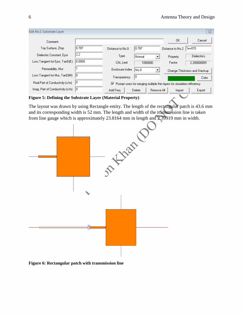
Figure 5: Defining the Substrate Layer (Material Property)
The layout was drawn by using Rectangle entity. The length of the rectangular patch is 43.6 mm
and its corresponding width is 52 mm. The length and width of the transmission line is taken
from line gauge which is approximately 23.8164 mm in length and 2.39919 mm in width.
Figure 6: Rectangular patch with transmission line

S-Parameter The simulation was setup to S-Parameter which are shown in figure 7 and figure 8. S-Parameters
are “Scattering Parameters” which are defined to represent the voltage ratios between different
ports
Following steps below were followed to setup S-parameter Simulation
Setup simulation port.
Setup simulation frequency range.
Plot simulation results.
Figure 7: Scattering Properties
Figure 8: Frequency Range

8 Antenna Theory and Design
Figure 9: Simulation Graph: Microstrip Patch
The equation below was used to find the original value of the reflection
𝟐𝟎𝒍𝒐𝒈𝟏𝟎(𝒏𝒐𝒏 𝒅𝑩 𝒗𝒂𝒍𝒖𝒆) = (𝒅𝑩 𝒗𝒂𝒍𝒖𝒆)
𝒏𝒐𝒏 𝒅𝑩 𝒗𝒂𝒍𝒖𝒆 = 𝟏𝟎 𝒅𝑩 𝒗𝒂𝒍𝒖𝒆
𝟐𝟎
Therefore, the non-Db value is 0.531.
The designed antenna almost resonates at 2.3 GHz. The 𝑆11 = -5.5dB is not well matched.
Therefore, the impedance matching needs to be improved by creating a slot. Therefore, 𝑆11 needs
to be nearby -20dB (non-dB value = 0.1). The new rectangular patch with a slot is shown below
with the simulation graph.

The option for the cut the polygon from the selected edge was chosen and the cut width and
length values are shown in Figure 10.
Figure 10: Cut the Polygon from the selected edges
Figure 11: Microstrip Patch with slot
Figure 12: Simulation Graph: Microstrip Patch
𝑆11 is nearby -18.0 dB

10 Antenna Theory and Design
The graphs related to the simulation are shown below:
Figure 13: 3D radiation pattern
This equation measures the peak value of radiated power divided by the average, which gives the
directivity of the antenna. The typical directivity of the patch microstrip antenna (3.2-6.3) / (5-8
dB) More the directivity more the focused or directional the antenna is. Even though there is no
isotropic antenna in real life but it is used as a common reference.

Figure 14: Azimuthal Pattern Directivity Display
Figure 15: Elevation Pattern Directivity Display

12 Antenna Theory and Design
Figure 16: Total Gain versus Frequency Display
From the graph it can be deduced that the total gain is around 4.8dBi at 2.31 GHz but the highest
total gain is approximately 5dBi in between 2.25 to 2.31 frequency range.
Figure 17: Total Field Directivity versus Frequency Graph
The total directivity is highest at 2.5 GHz which is around 7.6dBi but for 2.31GHz it is 7.55dBi

Figure 18: Directivity vs Elevation Angle
The total directivity for 2.31 GHz at 0 degree elevation angle is 7.55 dBi
Figure 19: Directivity vs Azimuth angle

14 Antenna Theory and Design
Gain, Directivity and Radiation Efficiency
𝑮 = 𝟒. 𝟖 𝒅𝑩𝒊
𝑫 = 𝟕. 𝟓𝟓 𝒅𝑩𝒊
𝒆𝒓 = (𝟕. 𝟓𝟓 − 𝟒. 𝟖)(−𝟏) = −𝟐. 𝟕𝟓 𝒅𝑩𝒊
𝑻𝒉𝒆𝒓𝒆𝒇𝒐𝒓𝒆, 𝒕𝒉𝒆 𝒓𝒂𝒅𝒊𝒂𝒕𝒊𝒐𝒏 𝒆𝒇𝒇𝒊𝒄𝒊𝒆𝒏𝒄𝒚 = 𝟎. 𝟓𝟑𝟎𝟖𝟖 𝒘𝒉𝒊𝒄𝒉 𝒊𝒔 𝟓𝟑 %
Conclusion and Further Discussion Problems Faced The calculations could have been more accurate if the approximate values were not taken. Also,
the center frequency moves from 2.3 GHz to 2.31GHz when the slot was implied to the
rectangular patch. For calculation for radiation efficiency, it gives the positive dB but that
positive value was changed to negative value.
Final Thoughts This lab helped us to get familiar with the Hyperlynx software. It would further help us to
understand the Antenna Theory concepts and calculation inside the transmission line.

References [1] http://en.wikipedia.org/wiki/Microstrip
[2] Rao, Nannapaneni Narayana. Fundamentals of Electromagnetics for Electrical and Computer
Engineering. Upper Saddle River, NJ: Pearson Prentice Hall, 2009. Print.
[3] Balanis, Constantine A. Antenna Theory: Analysis and Design. 3rd ed. Hoboken, NJ: Wiley
Interscience, 2005. Print.