antenna-coupled tes arrays for the bicep2/keck...
TRANSCRIPT

Antenna-coupled TES Arrays For The BICEP2/Keck and SPIDER polarimeters
A. Orlando*, R.W. Aikin*, M. Amiri**, J.J. Bock^*, J.A. Bonetti^, J.A. Brevik*, B. Burger**, P.K. Day^, J.P. Filippini*, S.R. Golwala*, M. Halpern**, M. Hasselfield**,
G. Hilton^, K. Irwin^, W.C. Jones^ M. Kenyon^, C.L. Kuo^ ,̂ A.E. Lange*, H.G. LeDuc^, B. Mates^, T. Morford*, H.T. Nguyen^, R.W. Ogburn*, C. Reintsema^, M.
Runyan , R. Sudiwala , A. Trangsmd , A.D. Turner', P. Wilson'
Department of Physics, California Institute of Technology, 1200 E.California Blvcl, Pasadena, CA 91125, USA ^Jet Propulsion Laboratory, 4800 Oak Grove Dr, Pasadena, CA 91109, USA
Department of Physics & Astronomy, University of British Columbia, 6224 Agricultural Road, Vancouver, British Columbia, V6T IZl, Canada
^NIST Quantum Devices Group, 325 Broadway, Boulder, CO 80305, USA ^Department of Physics, Princeton University, Princeton, NJ 08544, USA
^^Department of Physics, Stanford University, 382 Via Pueblo Mall, Stanford, CA 94305, USA
Abstract. The upcoming Cosmic Microwave Background (CMB) experiments BICEP2/Keck and SPIDER will be using planar arrays of polarization sensitive antenna-coupled TES bolometers, operating at frequencies between 96GEIZ and 220 GEIz. At 145 GlTz each array consists of 64 polarimeters (128 TES sensors) and four of these arrays are assembled together to make a focal plane. The detector arrays are integrated with a time-domain SQUID multiplexer developed at NIST and read out using the Multi-Channel Electronics (MCE) developed at the University of British Columbia. We present our progress in characterizing focal plane arrays and SQUID multiplexed readout for BICEP2 and SPIDER, describing testing procedures and giving a summary of dark measurements results, as well as preliminary optical measurements.
Keywords: Cosmic Microwave Background, polarization, TES bolometers, arrays. PACS: 07.57.Kp; 85.25.Pb; 98.80.Es; 95.85.Bh.
INTRODUCTION
One of the primary science goals of Cosmic Microwave Background (CMB) cosmology in the next decade is the degree-scale B-mode polarization induced by a gravitational wave background. A detection would not only confirm inflation, but it would also distinguish between models and constrain the physical processes causing it. Searching for B-mode polarization presents several challenges for focal plane detector development: a large number of sensitive detectors are required, wide frequency coverage for astrophysical foregrounds monitoring and excellent control of polarization systematics [1]. B1CEP2/Keck and SPIDER are experiments designed to measure the polarization of the CMB. SPIDER [2] is a balloon-borne experiment targeting the very large angular scale CMB polarization, while B1CEP2/Keck
[3] will be observing from the South Pole, aiming to detect the signature of inflation on scales ~ 1 degree. B1CEP2/Keck and SPIDER focal planes will employ planar arrays of dual-polarization anterma-coupled TES bolometers operating at frequencies between 96 GHz and 220 GHz. Single 96 GHz and 145 GHz devices have already been successfully tested, showing good electrical and optical performances [4, 5]. We have since built focal planes for both B1CEP2 and SPIDER, integrating the detector arrays with a time-domain SQUID multiplexer [6] and using the Multi-Charmel Electronics (MCE) [7] to readout the detectors. The uniformity of detector electrical and optical performances across the arrays is essential in order to achieve target sensitivities.
CP1185,Low Temperature Detectors LTD 13, Proceedings of the 13^ International Workshop edited by B. Cabrera, A. Miller, and B. Young
© 2009 American Institute of Physics 978-0-7354-0751-0/09/$25.00
471
Downloaded 27 Sep 2010 to 131.215.220.185. Redistribution subject to AIP license or copyright; see http://proceedings.aip.org/about/rights_permissions
FOCAL PLANE ARCHITECTURE
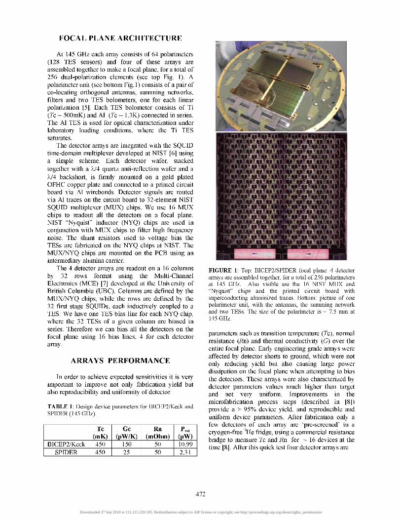
At 145 GHz each array consists of 64 polarimeters (128 TES sensors) and four of these arrays are assembled together to make a focal plane, for a total of 256 dual-polarization elements (see top Fig. 1). A polarimeter unit (see bottom Fig. 1) consists of a pair of co-locating orthogonal antennas, summing networks, filters and two TES bolometers, one for each linear polarization [5]. Each TES bolometer consists of Ti {Tc ~ 500mK) and Al {Tc ~ 1.3K) connected in series. The Al TES is used for optical characterization under laboratory loading conditions, where the Ti TES saturates.
The detector arrays are integrated with the SQUID time-domain multiplexer developed at NIST [6] using a simple scheme. Each detector wafer, stacked together with a X/4 quartz anti-reflection wafer and a X/4 backshort, is firmly mounted on a gold plated OFHC copper plate and connected to a printed circuit board via Al wirebonds. Detector signals are routed via Al traces on the circuit board to 32-element NIST SQUID multiplexer (MUX) chips. We use 16 MUX chips to readout all the detectors on a focal plane. NIST "Nyquist" inductor (NYQ) chips are used in conjunction with MUX chips to filter high frequency noise. The shunt resistors used to voltage bias the TESs are fabricated on the NYQ chips at NIST. The MUX/NYQ chips are mounted on the PCB using an intermediary alumina carrier.
The 4 detector arrays are readout on a 16 columns by 32 rows format using the Multi-Channel Electronics (MCE) [7] developed at the University of British Columbia (UBC). Columns are defined by the MUX/NYQ chips, while the rows are defined by the 32 first stage SQUIDs, each inductively coupled to a TES. We have one TES bias line for each NYQ chip, where the 32 TESs of a given column are biased in series. Therefore we can bias all the detectors on the focal plane using 16 bias hues, 4 for each detector array.
ARRAYS PERFORMANCE
In order to achieve expected sensitivities it is very important to improve not only fabrication yield but also reproducibility and uniformity of detector
TABLE 1: Design device parameters for BICEP2/Keck and SPIDER (145 GHz).
BICEP2/Keck SPIDER
Tc (mK) 450 450
Gc (pW/K)
150 25
Rn (mOhm)
50 50
Psat (pW) 10.99 2.31
FIGURE 1: Top: BICEP2/SPIDER focal plane: 4 detector arrays are assembled together, for a total of 256 polarimeters at 145 GHz. Also visible are the 16 NIST MUX and "Nyquist" chips and the printed circuit board with superconducting aluminized traces. Bottom: picture of one polarimeter unit, with the antennas, the summing network and two TESs. The size of the polarimeter is ~ 7.5 mm at 145 GHz.
parameters such as transition temperature {Tc), normal resistance {Rn) and thermal conductivity (G) over the entire focal plane. Early engineering grade arrays were affected by detector shorts to ground, which were not only reducing yield but also causing large power dissipation on the focal plane when attempting to bias the detectors. These arrays were also characterized by detector parameters values much higher than target and not very uniform. Improvements in the microfabrication process steps (described in [8]) provide a > 95% device yield, and reproducible and uniform device parameters. After fabrication only a few detectors of each array are 'pre-screened' in a cryogen-free ^He fridge, using a commercial resistance bridge to measure Tc and Rn for ~ 16 devices at the time [8]. After this quick test four detector arrays are
472
Downloaded 27 Sep 2010 to 131.215.220.185. Redistribution subject to AIP license or copyright; see http://proceedings.aip.org/about/rights_permissions

TABLE 2: Statistics on measured device parameters for BICEP2 and SPIDER arrays.
B1CEP2
SPIDER
average
Stcl clev
average
Stcl clev
Tc (mK) 517.0
3.9 (<1%) 515.0
4.35 (1%)
Gc (pW/K)
168.6
13.3 (8%) 33.9
2.92 (9 %)
P
2.5
0.05 (2%) 2.71
0.123 (5%)
R„ (mQ) 46.6
1.8 (4%) 47.5
3.25 (7%)
0.49 0,50 0,51 0.52 0.53 0.54 Tc (K)
1 DO 150 200 Gc (pW/K)
250
FIGURE 2: Histograms of transition temperature (Tc) (top) and thermal conductance at the transition temperature (Gc) (bottom) for a typical BICEP2 array.
integrated with MUX/NYQ chips into the focal plane assembly and any further tests on SQUlDs and detectors are performed in B1CEP2 and in the SPIDER test cryostat using the time-domain SQUID multiplexer and the MCE. MUX/NQY chips are usually screened at NIST prior to assembly.
Dark measurements
We perform a series of dark tests to characterize both SQUlDs and detectors: measurements of SQUlDs V-cp curves [9] to find 'optimal' operating points; noise measurements with the Ti TESs in superconducting and normal state to check for uniformity of SQUlD/shunt noise (and check for anomalies),load curves to measure detector parameters and noise measurements at different bias points on the Ti transition to study noise performances with the SQUID multiplexer.
Design device parameters at 145 GHz for B1CEP2 and SPIDER are listed in Table 1. Only the thermal conductance is different, due to different operational loading conditions (PsaO- In order to determine detector parameters we measure load curves at ~ 10-15 different focal plane temperatures ramping the detector bias simultaneously on all the 16 bias hues. From these data we fit Tc, Rn, Gc and /?for the Ti TES. Average measured device parameters for B1CEP2 and SPIDER are hsted in Table2 and typical Tc and Gc distributions for a B1CEP2 array are plotted in Fig. 2. All the engineering grade detector arrays tested so far show not only excellent uniformity, but results reproducible from array to array within few percent. This is very promising on the path to producing science grade arrays for B1CEP2/Keck and SPIDER.
We also measure load curves for the Al TESs, in order to check the transition temperature and verily we can bias them on transition with the TES bias range the MCE provides, without excessive power dissipation in the shunt resistors. We measure an average T^ ~1.34K and we recently confirmed we can bias all the Al TES sensors simultaneously on transition (under laboratory loading conditions) with only a small increase of the focal plane operating temperature.
Time-domain multiplexing is a powerful tool to readout a large number of detectors, but the limited sampling rate means that high frequency noise is aliased back into the signal band. The two main sources of high frequency noise are SQUID noise and detector noise. We measure an aliased SQUID noise (multiplexing at a frame rate of ~ 15 kHz) of ~ 25 pA/VHz. Because we don't have an independent measurement of unmultiplexed SQUID noise, we check the unahased SQUID noise level for a few pixels by acquiring 50 MHz 'raw' data with the MCE (using a special firmware developed for this purpose). We find that aliasing increases the SQUID noise level by a factor ~ 8. However, this is a few times smaller than the detector noise on transition for both SPIDER and B1CEP2.
473
Downloaded 27 Sep 2010 to 131.215.220.185. Redistribution subject to AIP license or copyright; see http://proceedings.aip.org/about/rights_permissions

POL_A POLJB
40 45 50 U 60 U T_lib (K)
40 45 50 55 60 65 Tjbb (K)
40 50 60 70 opt-eff(%)
80 90
FIGURE 3: Top: example of saturation power (Psat) as function of cold load temperature (T^B) for TES polA and TES polB on the same pixel. Bottom: measured optical efficiencies for an engineering grade 145 GEIz detector array. The average optical efficiency is ~ 67%..
High frequency intrinsic detector noise is filtered with a Nyquist inductor to reduce the amount of in-band ahasing. The inductance has to be large enough to avoid degradation due to ahasing, but still be small enough for detector bias stability. So far we have tested NYQ chips with inductances of ~ 0.5|j,H and 1.35|aH with both BICEP2 and SPIDER arrays. We have measured the noise spectra at different bias points on the Ti transition and compared them with a model to determine the amount of ahasing. We find that the optimal inductance is 1.35|j,H., both for SPIDER and BICEP2 detectors.
Optical Efficiency Measurements
The first optical efficiency measurements on focal plane arrays have been performed in BICEP2 using an internal blackbody source (an HR-10 covered Al plate, with a distributed heater, mounted inside the cryostat at ~ 40K). We have measured detectors load curves at several different optical loadings, corresponding to blackbody temperatures between 42K and 62K. Figure 3 (top plot) shows an example of change in detector saturation power as a function of optical loading for
two TESs on the same pixel (corresponding to the two orthogonal linear polarizations). Figure 3 (bottom) shows an histogram of measured optical efficiencies (at 145 GHz) for the same array. The average optical efficiency is ~ 67%, consistent with single device measurements [5]. These prehminary results are very promising.
FUTURE PLANS
At the time of this writing a second generation engineering grade focal plane installed in BICEP2 is being tested for the first time under laboratory loading conditions, looking at thermal sources outside the dewar: tests are underway to map beams and measure filter spectra for the full focal plane arrays. After completing optical characterization, a BICEP2 science grade focal plane will be assembled and fully characterized.
BICEP2 will employ only 145 GHz detector arrays, while SPIDER/Keck receivers will employ arrays operating at 96 GHz, 145 GHz and 220 GHz. Dark and optical characterization of SPIDER/Keck 96 GHz detector arrays will start soon. Single 220 GHz devices will be fabricated and tested.
ACKNOWLEDGMENTS
We would like to thank the Gordon and Betty Moore Foundation, the National Aeronautics and Space Administration, the JPL Research and Technology Development Fund and the W. M. Keck Foundation.
REFERENCES
1. J. J.Bock et al., "Task Force on Cosmic Microwave Background Research", astro-ph 0604101 (2006).
2. B.P.Crilletal., ProcSPIE 7010,(2008). 3. H.T.Nguyen etal.,Proc5P/£' 7020,(2008); 4. J.A.Bonetti et al, J. Low Temp. Phys, 151 (2008). 5. C. L. Kuo et al, Proc SPIE 7020, (2008). 6. P.de Korte et aX.,Review of Scientific Instruments lA,
3807-3815(2003). 7. E S.Battistelli et al, J. Low Temp. Phys, (2008). 8. J.A.Bonetti et al, this proceeding. 9. E.S.Battistellietal, Proc ̂ Pffi 7020,(2008).
474
Downloaded 27 Sep 2010 to 131.215.220.185. Redistribution subject to AIP license or copyright; see http://proceedings.aip.org/about/rights_permissions