ansys hfss po region - engineering simulation & 3 … sub-refl ector is usually not very large...
TRANSCRIPT
HFSS PO Hybrid Region
IntroductionThe design of electrically large systems poses many challenges. Electromagnetic simulations can relatively quickly assess options and trade-off s before any physical testing. Ansys HFSS off ers fl ex-ible 3D simulation technology for accurate and fast modeling of electrically large designs. HFSS-IE (3D Method of Moments) and PO (Physical Optics) solvers were introduced as an effi cient alternative to FEM (Finite Element Method) solver for metallic electrically large structures. Introduced in R14, hybrid solver combines FEM and IE techniques, leveraging the strength of both methods for accurate and effi cient simulations. This paper shows applications for a new R17 feature, PO Hybrid Regions. PO Region is a fast alternative to IE Region for simulation of the smooth conducting or dielectric struc-tures that are electrically very large. Three applications are discussed: horn fed refl ector, refl ector with radome, and Cassegrain refl ector. Each application leverages expanded hybrid solver enabled in new release for accurate and effi cient simulation. These applications use hybrid regions: horn fed refl ector modeled with FE-BI and PO hybrid regions; refl ector with radome modeled with FE-BI, Metallic PO and Dielectric PO regions; and Cassegrain refl ector modeled with FE-BI, IE, and PO regions. FE-BI regions are FEM domains surrounded by a boundary that uses HFSS-IE (Integral Equation) formulation to truncate an open space. IE Regions are objects or sheets solved with HFSS-IE solver. PO Regions are dielectric objects and perfectly conducting objects or sheets solved with physical optics formulation.
PO Hybrid regionsHFSS models are growing in complexity and fi delity as compute resources become more readily available. For example, HFSS is being used to model installed antenna performance including things like feeding networks and refl ector systems, rather than simply modeling the antenna in free space. Managing these multi-part models can become very complex if not impossible, especially when the engineer who is modeling the full system isn’t the one necessarily design-ing each individual part. 3D Components facilitate the design process by providing an infra-structure to effi ciently manage complex models and freely share parts among collaborators, customers and/or vendors.
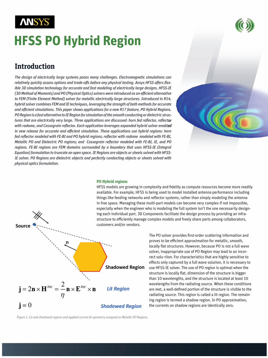
The PO solver provides fi rst-order scattering information and proves to be effi cient approximation for metallic, smooth, locally fl at structures. However, because PO is not a full wave solver, inappropriate use of PO Region may lead to an incor-rect solu¬tion. For characteristics that are highly sensitive to eff ects only captured by a full wave solution, it is necessary to use HFSS-IE solver. The use of PO region is optimal when the structure is locally fl at, dimension of the structure is bigger than 10 wavelengths, and the structure is located at least 10 wavelengths from the radiating source. When these conditions are met, a well-defi ned portion of the structure is visible to the radiating source. This region is called a lit region. The remain-ing region is termed a shadow region. In PO approximation, the currents on shadow regions are identically zero.
Figure 1. Lit and shadowed regions and applied current for geometry assigned as Metallic PO Regions.
and effi cient simulations. This paper shows applications for a new R17 feature, PO Hybrid Regions. PO Region is a fast alternative to IE Region for simulation of the smooth conducting or dielectric struc-tures that are electrically very large. Three applications are discussed: horn fed refl ector, refl ector with radome, and Cassegrain refl ector. Each application leverages expanded hybrid solver enabled in new release for accurate and effi cient simulation. These applications use hybrid regions: horn

Figure 3. Project Manager window lists hybrid regions of all types including FE-BI.
One example perfectly suited for PO Region workfl ow is horn fed refl ector antenna at high frequency, where the antenna size is electrically large.
Horn fed refl ector antennaAn electrically large refl ector of 22 wavelengths in diameter is fed with a rectangular horn. To model the system using a hybrid solution with the refl ector solved as a PO Region, all geome-try objects are placed in HFSS Design. The horn geometry is surrounded by an air box named RadiatingSurface. The faces of this object are assigned as Hybrid FE-BI Region, the assignment corresponds to radiation FE-BI boundary in previous versions of Ansys HFSS. To assign, select the air volume surrounding FEM part of a design, and use menu item HFSS > Hybrid > Assign Hybrid > FE-BI. The refl ector is modeled as a 2D sheet object with PerfE boundary condition assigned. This sheet object is modeled as a Hybrid Metallic PO Region. To assign, select the refl ector, and use menu item HFSS > Hybrid > Assign Hybrid > PO Region. The dialog for Hybrid Region opens, showing the default name and type selection as PO Region. Since a user may decide to change an assignment to IE Region, the dialog shows these types as radio button selections.
All Hybrid regions are listed under Hybrid Regions entry in Project Manager.
After solution has completed, standard result reports like fi eld plots, S-parameters, and Far Field characteristics are available.
The same geometry was solved with refl ector assigned as an IE Region. We can see that the radiation patterns are almost identical and diff er only for back lobes, while PO Region option signifi cantly saves computational resources.
After solution has completed, standard result reports like fi eld plots, S-parameters, and Far
The same geometry was solved with refl ector assigned as an IE Region. We can see that the radiation patterns are almost identical and diff er only for back lobes, while PO Region option
Figure 4. E-fi eld plots in FE-BI region and J-fi eld plot on PO Region.
Figure 2. Refl ector assigned as hybrid Metallic PO Region.

Note that PO Regions may be used together with other useful features like 3D Components. For parametric sweeps that vary the distance between assembled 3D components, it is possible to preserve and re-use the component-level meshes between these variations. For example, if a horn and a reflector are defined as 3D Components with enabled “Do Mesh assembly” option, one can do a placement study running the parametric sweep over the distance between the horn and the antenna, recycling the mesh to speed up the parametric sweep simulations.
Project “Reflector_antenna_PO_Region” contains the designs for simulations described above. Note several limitations of PO Region option. First, every conducting material of metallic PO Region will be treated as perfect conductor, and every surface will be treated as PerfE bound-ary condition disregarding actually assigned materials and boundary conditions. The warning message will be issued if PO Region is assigned on a metal object or a boundary condition that is not a perfect electric conductor. Assigning PO Region to a dielectric object automati-cally turns this hybrid region to a Dielectric PO Region. Second, if there are multiple sources modeled with multiple disjoint FE-BI boundaries that makes it hard to accurately define shadow region, PO region solver does not provide reliable results. Furthermore, the solver will report error message when it detects that a shadow region due to each FE-BI region does not mostly overlap.
Figure 6. 3D Component data settings for mesh recycling and resulting radiation patterns for different distances between the horn and the reflector.
Figure 5. Comparison of the designs that use IE Region and PO Region options to model a reflector: Radiation pattern and computational resources required for each design.
Reflector RAM Time(1coreused)assignedas 1stpass Mesh+1stpassIE Region 2.49GB 10 min 31secPO Region 1GB 1 min 27 sec
Figure 7. Example of two horns modeled with two disjoint FEBI boundaries. For this case, shadow regions for each FE-BI box are practically the same, making this design suitable for PO Region option. If it is hard to accurately define shadow region, PO region solver may not provide reliable results.

Dielectric PO Region: antenna with radomeA hybrid PO Region may be assigned to dielectric object as well.
Application example for dielectric PO Region: antenna with radomeThe Dielectric PO Region option is well suited for simulating antennas covered with radomes. To model the system using Dielectric PO Region, all geometry objects are placed in a single HFSS Design. Horn geometry is surrounded by the air box that is assigned as a Hybrid FE-BI Region. The radome geometry should be a standalone 3D object assigned with dielectric material. This object is also assigned as a hybrid Dielectric PO Region. To assign, select the radome, and use menu item HFSS > Hybrid > Assign Hybrid > PO Region. The Dielectric PO Region should not touch any other model geometry. This option may be used in the same design together with other hybrid regions. Below is the example of refl ector with the fl at FR4 radome between the refl ector and the horn.
Figure 8. Lit and shadowed regions and applied fi elds for geometry assigned as Dielectric PO Regions
Figure 9. Three hybrid regions are assigned: FE-BI for air box around horn, Metallic PO for PerfE refl ector, and Dielectric PO for FR4 radome.

ANSYS, Inc.www.ansys.com
© 2016 ANSYS, Inc. All Rights Reserved.
MKT000000000
Note some limitations for Dielectric PO region: no boundary condition may be assigned on the surface of Dielectric PO region; Dielectric PO Region can’t touch any other metallic IE or PO regions. However, several touching dielectrics like layers of the radome may be assigned as one Hybrid dielectric PO Region.
Cassegrain refl ector: IE and PO Hybrid regions in one design Hybrid PO Regions may be combined with IE Hybrid regions if desired. For applications like Cassegrain refl ector, there are 2 regions suitable for IE solver: a sub-refl ector and a main refl ector. A sub-refl ector is usually not very large electrically, but accuracy of fi eld solution on the sub-refl ector is very important. A main refl ector may be electrically very large and smooth making PO approximation justifi ed for the main refl ector. Below is the solved fi eld for Casseg-rain system with relatively small main refl ector: the air box around the horn is assigned as a FE-BI Region, the sub-refl ector is assigned as a Metallic IE Region, and the main refl ector is assigned as a Metallic PO Region.
Figure 10. Solved fi elds for design with three hybrid regions including Dielectric PO Region for FR4 plate radome. Only a quarter of geometry is displayed for a fi eld plot. In Radiation Pattern plot, the black dotted line represents the far fi eld of the refl ector without radome, and the red line refers to the design with FR4 plate between the horn and the refl ector.
SummaryThe PO region is a viable option for many electrically very large geometries. With an under-standing of the limitations, users can generate accurate results using this very effi cient method. Metallic PO Region is a fast alternative to IE Region for simulation of the smooth conducting structures that are electrically very large. Dielectric PO Regions can be used for simulating standalone electrically large dielectric objects. PO Regions may be fl exibly combined with other hybrid regions and other ANSYS HFSS features for effi cient simula-tions of electrically very large systems.