answers - ies masteriesmaster.org/public/archive/2016/im-1478444802.pdfmechanism are: pendulum pump,...
TRANSCRIPT

Office : F-126, Katwaria Sarai, New Delhi-110016 (Phone : 011-41013406, 7838813406, 9711853908)
Website : www.iesmaster.org E-mail: [email protected]
ESE-2017 PRELIMS TEST SERIESDate: 6th November, 2016
24. (d)
25. (a)
26. (b)
27. (a)
28. (c)
29. (b)
30. (d)
31. (b)
32. (b)
33. (d)
34. (b)
35. (c)
36. (b)
37. (b)
38. (d)
39. (b)
40. (c)
41. (c)
42. (d)
43. (d)
44. (c)
45. (a)
46. (c)
47. (c)
48. (c)
49. (a)
50. (a)
51. (b)
52. (d)
53. (a)
54. (c)
55. (c)
56. (b)
57. (c)
58. (c)
59. (b)
60. (b)
61. (c)
62. (a)
63. (b)
64. (d)
65. (c)
66. (c)
67. (c)
68. (b)
69. (c)
70. (c)
71. (a)
72. (b)
73. (d)
74. (b)
75. (c)
76. (b)
77. (d)
78. (c)
79. (d)
80. (d)
81. (b)
82. (a)
83. (c)
84. (b)
85. (d)
86. (c)
87. (b)
88. (d)
89. (c)
90. (b)
91. (a)
92. (c)
93. (c)
94. (c)
95. (b)
96. (b)
97. (d)
98. (c)
99. (c)
100. (d)
101. (a)
102. (c)
103. (d)
104. (b)
105. (c)
106. (d)
107. (a)
108. (c)
109. (b)
110. (c)
111. (c)
112. (b)
113. (b)
114. (c)
115. (a)
116. (c)
117. (d)
118. (a)
119. (d)
120. (d)
121. (b)
122. (d)
123. (b)
124. (b)
125. (c)
126. (a)
127. (a)
128. (b)
129. (d)
130. (c)
131. (b)
132. (d)
133. (b)
134. (b)
135. (d)
136. (d)
137. (a)
138. (d)
ANSWERS
1. (c)
2. (d)
3. (c)
4. (c)
5. (c)
6. (a)
7. (b)
8. (b)
9. (d)
10. (d)
11. (c)
12. (c)
13. (d)
14. (d)
15. (b)
16. (b)
17. (b)
18. (b)
19. (c)
20. (d)
21. (d)
22. (b)
23. (c)

IES M
ASTER
(2) ME (Test-7), Objective Solutions, 6th November 2016
139. (b)
140. (a)
141. (d)
142. (d)
143. (d)
144. (c)
145. (a)
146. (a)
147. (c)
148. (a)
149. (c)
150. (a)
151. (c)
152. (d)
153. (b)
154. (a)
155. (d)
156. (b)
157. (a)
158. (a)
159. (a)
160. (a)

IES M
ASTER
(3) ME (Test-7), Objective Solutions, 6th November 2016
Sol–1: (c)Here, shortest link OA = 3 cm and thelink adjacent to the shortest link is fixed,hence it would result in crank-rockermechanism. OA will act as a crank.
Sol–2: (d)Sol–3: (c)
VB/A = 2 2B AV V = 2 230 40 50 m/s=
Sol–4: (c)Radial component of acceleration of pointC.
=2 2V 10 5= =CD CD
CD =210 100 20cm= =5 5
Sol–5: (c)Coriolis component of acceleration =
2 v = 2 602
60
× 10 = 240 cm / s
Sol–6: (a)Inversions of single slider crankmechanism are: Pendulum pump,oscillating cylinder engine, crank andslotted lever, whitworth mechanism,snome engine.
Sol–7: (b)Sol–8: (b)
Sensitiveness of the governor
=
2 12 1
1 2
2 N NN N =N N N
Sol–9: (d)
BVBE = C
BCV
=CE
0.50.25 = cV
0.1 Vc = 0.2m/s
Sol–10: (d)• A governor is said to be isochronous when
the equilibrium speed is constant for allradii of rotation of the balls. Theisochronism is a stage of infinite
resistivity.• A governor is said to hunt if the speed of
the engine fluctuates continuously aboveand below the mean speed. This is causedby a too sensitive governor which changesthe fuel supply by a large amount whena small change in the speed of rotationtakes place.
• A governor is said to be stable when forevery speed within the working range,there is only one radius of rotation of thegovernor balls at which the governor is inequilibrium.
• For a stable governor, if the equilibriumspeed increases, the radius of governorballs must also increase. In the case of anunstable governor, the radius of rotationdecreases, as the speed increases.The greater the lift of the sleevecorresponding to a given fractional changein speed, the greater is the sensitivenessof the governor.
Sol–11: (c)Considering the case of a stable governor,
Fc = ar –b 1600 = 400 a – b ...(i)
800 = 240 a – b ...(ii)1–2 800 = 160 a a = 5 and b = 400Since, both ‘a’ and ‘b’ are positive, henceour assumption of this being a stablegovernor is correct.Now, for isochronous governors FC = arHence, initial tension must be increasedby 400 N.
Sol–12: (c)The given arrangement has no. of links
5= and no. of joints j = 5, no. of pairsp = 5.
Applying the equation, 2p 4,=
LHS = 5, RHS = 2 × 5 – 4 = 6Thus, LHS < RHS
IES M
ASTER
(4) ME (Test-7), Objective Solutions, 6th November 2016
Further, applying the equation, j = 3 22
LHS = 5, RHS = 3 5 2 5.5=2
Hence, LHS < RHSSince, LHS < RHS, hence, it isunconstrained kinematic chain, i.e. therelative motion is not completelyconstrained. This type of chain is of littlepractical importance.
Sol–13: (d)The product of crank pin effort FT andcrank pin radius r known as crank effort.
Crank effort T = FT × r
=
sF sin rcos
= sF rsin cos tan
We know that
sin = rsin
sin = rsin sin=n
cos =2
22
sin1 sin 1=n
= 2 21 n sinn
tan = 2 2
sin sin n=cos n n sin
= 2 2
sinn sin
T = s 2 2
cos sinsinF rn sin
= s 2 2
sin2sinF r2 n sin
Since 2sin is very small compacted ton2, hence neglecting 2sin we have
T = s ssin2sinF r F OM=2n
Sol–14: (d)Inversion of single slider crankchain are:Pendulum pump; oscillating cylinderengine; Rotory internal combustionengine, crank and slotted lever quickreturn motion mechanism and whitworthquick return motion mechanism.Inversion of Four bar mechanismare:Beam engine; coupling rod of a locomotive;Watt’s indicator mechanismInversions of Double slider crankmechanism are:Oldham’s coupling; Elliptical trammel andscotch yoke mechanism.
Sol–15: (b)Mass moment of inertia of flywheelI = mk2 = 300 × 12 = 300 kg-m2
Angular velocity of flywheel
= 100 2 10 rad/s=360 3
Angular velocity of precession
p = 6 rad/s
Gyroscopic couple = pI
= 10100 6 6 kNm.=3
Sol–16: (b)Beam engine mechanism is an inversionof four-bar mechanism, whereaswhitworth quick return mechanism is aninversion of single slider crankmechanism. Oldham coupling andelliptical trammel mechanisms areinversions of double slider crankmechanism.
Sol–17: (b)A governor is said to be isochronous whenthe equilibrium speed is constant for allradii of rotation of the balls within theworking range, neglecting friction.

IES M
ASTER
(5) ME (Test-7), Objective Solutions, 6th November 2016
Sol–18: (b)Toggle mechanism has many applicationswhere it is necessary to overcome a largeresistance with a small driving force. Astone crusher utilizes this mechanism toovercome a large resistance with a smallforce. It can be used in numerous toggleclamping devices, for holding work pieces.The figures of Hart, watt and beam enginemechanism are:Beam Engine Mechanism
Lever(Link 4)
Pistonrod
Cylinder
Frame (Link 1)Crank
(Link 2)
B
A
Link 3
E
D C
Watt Mechanism
O1
1P
BO
B
A
PA
Hart Mechanism
C
O
F
QO1
P
AB
MN
D
E
Sol–19: (c)This is Roberts mechanism and point Pwill trace an approximate straight line.
Sol–20: (d)For a Porter governor,
N2 =
tanM 1M tan2 895m h
Thus, h 21
N
Hence, dhdN 3
1N .
Sol–21: (d)A body in motion will be subjected toCorioli’s acceleration when that body isrestrained to rotate while sliding overanother body.
Sol–22: (b)A round bar in a round hole does notform a constraint pair as round bar canrotate as well as slide. A square bar in asquare hole forms a sliding pair. A verticalshaft in a footstep bearing may rotate inthe bearing or it may move upwards. Thisis a case of incompletely constrainedmotion. Since load is placed on the shaftto prevent axial upward movement of theshaft, hence the motion of the pair is saidto be successfully constrained motion.
Sol–23: (c)Applied load convert an incompletelyconstrained motion into successfullyconstrained motion. The motion of pistonand cylinder in IC engine is successfullyconstrained because it can onlyreciprocate. Its rotation is restricted bymeans of gudgeon pin between piston andconnecting rod.
Sol–24: (d)
Bar(Link 2)
A Slider(Link 3)
P Slottedplate (Link 4)
Slider (Link 1)
B
IES M
ASTER
(6) ME (Test-7), Objective Solutions, 6th November 2016
X'B Rx O X
Y'
QPy
AY
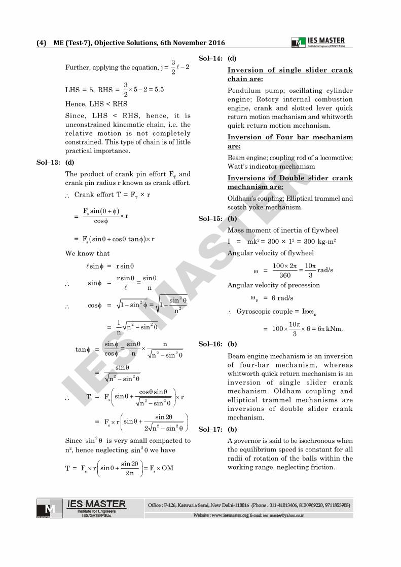
Let us take OX and OY as horizontal andvertical axes and let the link BA beinclined at an angle with the horizontal,as shown in figure. Now the co-ordinatesof the point P on the link BA will be
x = PQ AP cos ;
and y = PR BP sin
or xAP = ycos ; and sin
BP
Squaring and adding,
2 2
2 2x y
AP BP = 2 2cos sin 1
This is the equation of an ellipse. Hencethe path traced by point P is an ellipsewhose semi-major axis is AP and semi-minor axis is BP.
Sol–25: (a)The initial and installation costs ofequipments of robots are quite high.
Sol–26: (b)Yaw, also called, wrist yaw, facilitatesrightward or leftward swivellingmovement of the wrist.
Sol–27: (a)The cartesian or rectilinear robot alsotermed as gantry robot, has threemutually perpendicular axes which definea rectangular work volume.
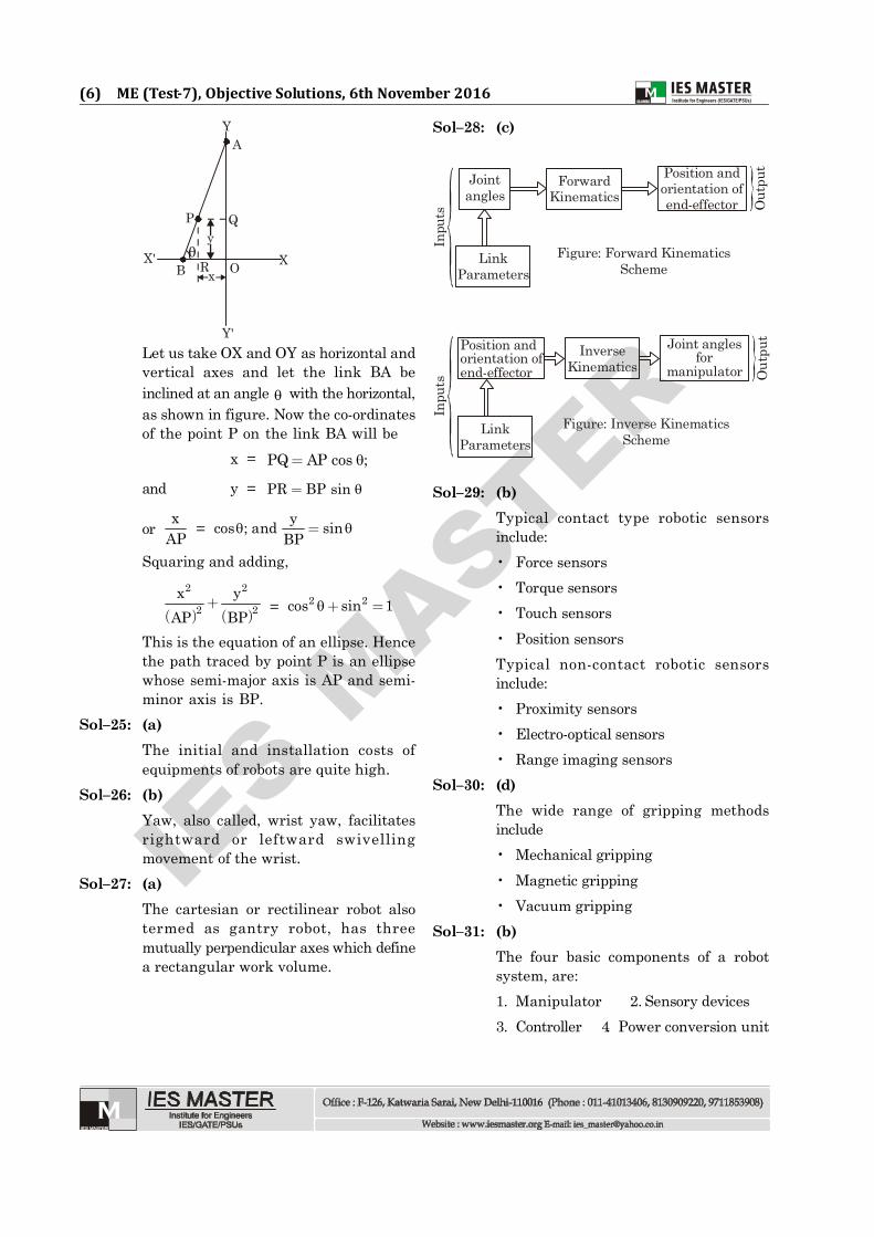
Sol–28: (c)
Jointangles
ForwardKinematics
Position andorientation ofend-effector
LinkParameters
Out
put
Figure: Forward KinematicsScheme
Inpu
ts
Position andorientation ofend-effector
InverseKinematics
Joint anglesfor
manipulator
LinkParameters
Out
put
Figure: Inverse KinematicsScheme
Inpu
ts
Sol–29: (b)Typical contact type robotic sensorsinclude:• Force sensors• Torque sensors• Touch sensors• Position sensorsTypical non-contact robotic sensorsinclude:• Proximity sensors• Electro-optical sensors• Range imaging sensors
Sol–30: (d)The wide range of gripping methodsinclude• Mechanical gripping• Magnetic gripping• Vacuum gripping
Sol–31: (b)The four basic components of a robotsystem, are:1. Manipulator 2. Sensory devices3. Controller 4. Power conversion unit
IES M
ASTER
(7) ME (Test-7), Objective Solutions, 6th November 2016
Powerconversion
unit
Controller
Manipulator TV camera(visual sensory device)
Joint (contains actuator,
transmission, andsensor)Link
Power toactuators on
joints
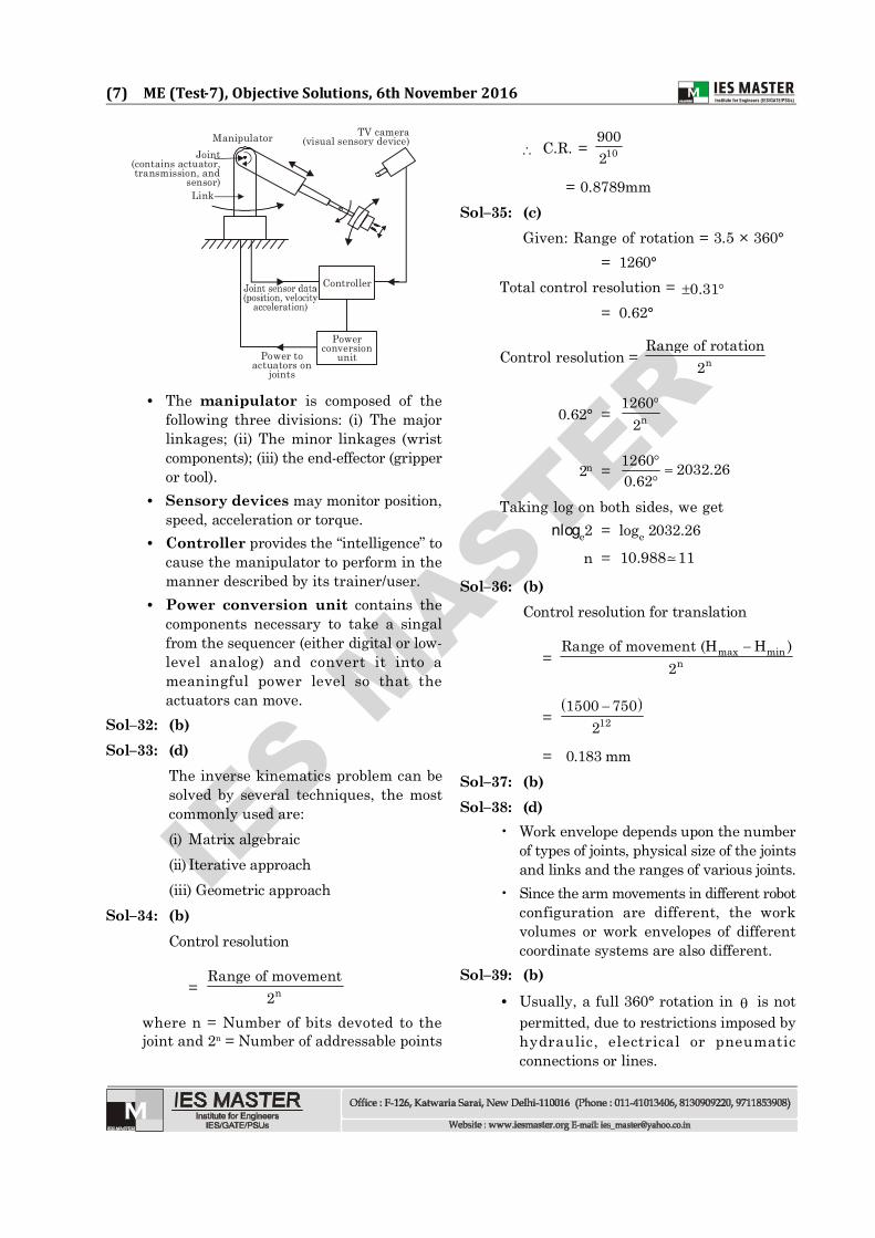
• The manipulator is composed of thefollowing three divisions: (i) The majorlinkages; (ii) The minor linkages (wristcomponents); (iii) the end-effector (gripperor tool).
• Sensory devices may monitor position,speed, acceleration or torque.
• Controller provides the “intelligence” tocause the manipulator to perform in themanner described by its trainer/user.
• Power conversion unit contains thecomponents necessary to take a singalfrom the sequencer (either digital or low-level analog) and convert it into ameaningful power level so that theactuators can move.
Sol–32: (b)Sol–33: (d)
The inverse kinematics problem can besolved by several techniques, the mostcommonly used are:(i) Matrix algebraic(ii) Iterative approach(iii) Geometric approach
Sol–34: (b)Control resolution
= nRange of movement
2where n = Number of bits devoted to thejoint and 2n = Number of addressable points
C.R. = 109002
= 0.8789mmSol–35: (c)
Given: Range of rotation = 3.5 × 360°= 1260°
Total control resolution = 0.31= 0.62°
Control resolution = nRange of rotation
2
0.62° =
n1260
2
2n =
1260 2032.260.62
Taking log on both sides, we getnloge2 = loge 2032.26
n = 10.988 11
Sol–36: (b)Control resolution for translation
= max min
nRange of movement (H H )
2
=
121500 750
2
= 0.183 mmSol–37: (b)Sol–38: (d)
• Work envelope depends upon the numberof types of joints, physical size of the jointsand links and the ranges of various joints.
• Since the arm movements in different robotconfiguration are different, the workvolumes or work envelopes of differentcoordinate systems are also different.
Sol–39: (b)• Usually, a full 360° rotation in is not
permitted, due to restrictions imposed byhydraulic, electrical or pneumaticconnections or lines.

IES M
ASTER
(8) ME (Test-7), Objective Solutions, 6th November 2016
• Also, there is minimum as well asmaximum extension due to mechanicalrequirements. Consequently, the overallvolume or work envelope is a portion of acylinder.
Sol–40: (c)
Accuracy = Control Resolution 3
2
Control resolution = nRange of travel
2
= 10800 0.78125mm2
Accuracy = 0.78125 3 0.06
2
= 0.571 mmSol–41: (c)
Number of slots, S = 15Number of emitter detector pairs, n = 2Angular control resolution, Ac = 0.06°Range of rotation = 2 360
Gear reduction ratio, G =
nc
360S A 2
=
2360
15 0.06 2
= 100Sol–42: (d)
• All these factors govern the speed ofmovement.
• Heavier parts and higher placementaccuracy demand slower movement whilethe lighter parts can be moved at fasterspeeds.
• The speed ‘varies’ from one point toanother.
Sol–43: (d)Selection of a robot depends upon theparticular application, for which followingfactors should be considered.
• Load capacity required• Adequate number of DoF• Speed of movement• Reach (range of travel)
Sol–44: (c)Robots can be categoriesed as follows:1. Tele-robots: These are guided by
human operators through remotecontrol
2. Telepresence robots: This type of robotis similar to a tele-robot with adifference that it is provided with afeedback of video, sound and other data.
3. Mobile robots: These robots are sodesigned as to navigate and carry outthe task with the intervention ofhuman beings.
4. Autonomous robots: These robotsperform their tasks independently andreceive their power from theirenvironment
5. Androids: These robots are built tomimic humans.
6. Static + industrial robots: These arethe widely used arms employed infactories and laboratories all over theworld.
Sol–45: (a)• A robot is a lighter and more portable
equipment comparatively.• A robot’s programming is different from
the part programming used in NC machinetools.
Sol–46: (c)• Spherical configuration has a telesocpic
arm which pivots about a horizontal axisand also rotates about a vertical axis.
• Owing to mechanical and/or actuatorconnection limitations, the work envelopeof such a robot is a portion of sphere.
Sol–47: (c)Most popular drive technologies are– Electric drives– Hydraulic drives
IES M
ASTER
(9) ME (Test-7), Objective Solutions, 6th November 2016
– Pneumatic drives• Many robotic manipulators today use
electric drives in the form of either D.C.servomotors or D.C. stepper motors.However, for high-speed manipulation ofsubstantial loads, hydraulic drives arepreferred, but their major draw back istheir lack of cleanliness.
• Electrically powered robots have theadvantage of accurate movements andquiet operation.
• They also offer a wide range of payloadcapacity, accompanied by an equally widerange of costs.
Sol–48: (c)The advantages of pneumatic drives are:Simple construction, relatively inexpensive,fast and reliable. The disadvantages ofpneumatic system are smaller payloads, themass inertia and delayed response of therobot, arm due to the sponginess andreduced repeatability.
Sol–49: (a)By extrusion process, it is possible tomake components which have aconstant cross-section over any lengthas can be had by the rolling process.Forward Hot ExtrusionIn the forward hot extrusion, the flowof metal is in the forward direction, i.e,the same as that of the ram. In forwardextrusion, the problem of friction isprevalent because of the relative motionbetween the heated metal billet and thecylinder walls. This is particularlysevere in the case of steels because oftheir higher extrusion temperatures. Toreduce this friction, lubricants are tobe used. At lower temperatures, amixture of oil and graphite is generallyused. The problem of lubrication getscompounded at the higher operatingtemperatures. Molten glass is generallyused for extruding steels, this stays inliquid from at the operatingtemperatures and provides necessaryheat insulation to the hot metal billetin addition to lubrication. To reduce thedamage to equipment, extrusion is
finished quickly and the cylinder iscooled before further extrusion.Backward Hot ExtrusionIn order to completely overcome thefriction, the backward hot extrusion, isused. In this, the metal is confined fullyby the cylinder. The ram which housesthe die, also compresses the metalagainst the container, forcing it to flowbackwards through the die in the hollowplunger or ram. It is termed backwardbecause of the opposite direction of theflow of metal to that of ram movement.Thus, the billet in the container remainsstationary and hence no friction. Also,the extrusion pressure is not affectedby the length of the billet in theextrusion press since friction is notinvolved. The surface quality achievedis generally good since there is no hotcracking due to the friction between thebillet and the extrusion cylinderinterface. The disadvantage of backwardextrusion is that the surface defects ofthe billet would end up in the finalproduct unlike direct or forwardextrusion where these are discarded inthe extrusion container. Thoughadvantageous, this process is notextensively used because of the problemof handling extruding metal coming out
through the moving ram.
Sol–50: (a)Heat input rate P = VIHeat required for melting will beproportional to volume of metal to bemelted, which in turn would depend onthickness of the metal. Since the thicknessreduces by half, so the power requiredwould also be half. Thus, keeping thesame voltage, we may decrease the currentby half.
Sol–51: (b)The various radii in the die cavity cansignificantly affect the formation ofdefects. The material follows a largecorner radius better than a smallradius. With small radii, the materialcan fold over itself and produce a lap.
IES M
ASTER
(10) ME (Test-7), Objective Solutions, 6th November 2016
Sol–52: (d)
Thickness of skin time
t2 = 12
t2 = 0.5 0.709
t2 –t1 = 0.709 1 0.291
= – 29%Hence, the thickness decreases by 29%.
Sol–53: (a)Good collapsibility in the molding sandallows the casting to shrink while coolingand the main cause of hot tearing isimproper solidification during cooling.
Sol–54: (c)Inclusions are mainly caused due toreaction of molten metal with theenvironment or with crucible or moldmaterial.
Sol–55: (c)The microstructure of a particular materialcontributes to the detrimental factors, suchas microporosity, microhardness,compositional variations etc.
Sol–56: (b)Sol–57: (c)
Both deoxidation and purging are used toremove dissolved gases from the moltenmetal.
• purging means flushing the metal withan inert gas
• in case the dissolved gas is O2, the moltenmetal is deoxidised.
Sol–58: (c)Undercut is a welding defect caused dueto reduction of cross sectional thickness ofbase metal.
Sol–59: (b)(A) Investment casting- cams and valves(B) Slush casting- Ornamental anddecorative objects.(C) Expendable pattern casting - lost foamprocess
(D) Permanent mold casting-kitchenware(E) Die casting-Hand tools
Sol–60: (b)In true centrifugal casting hollowcylindrical parts such as pipes, gunbarrelsand street lamp posts are produced. Inthis the molten metal is poured in arotating mold.
Sol–61: (c)A small draft or taper is provided in sandmold patterns to enable removal of thepattern without damaging the mold.
Sol–62: (a)Process planning: Selecting sequence ofoperationsRouting sheet: Standard time foroperations.CAPP: Generative systemMRP: Inventory control
Sol–63: (b)CAPP: Computer aided process planningdecreases the lead time hence leading tohigher productivity.
Sol–64: (d)MRP-II- Manufacturing resource planning,through feedback controls all aspects ofmanufacturing planning.
Sol–65: (c)Sol–66: (c)
A. Just in time production - zeroinventoryB. FMS - AGVC. CIM - MRPD. Group technology -opitz system
Sol–67: (c)CAD/CAM: This combination allows thetransfer of information from the designstage into the stage of planning for themanufacture of a product.
Sol–68: (b)Sol–69: (c)Sol–70: (c)
In both arc welding and oxyfuel welding,coalescing of materials takes place bymeans of heat.
IES M
ASTER
(11) ME (Test-7), Objective Solutions, 6th November 2016
Sol–71: (a)Sol–72: (b)Sol–73: (d)
Twin boundary separates two orientationsthat are mirror image of one another.Twin boundaries can be annealing twinsor mechanical twins.
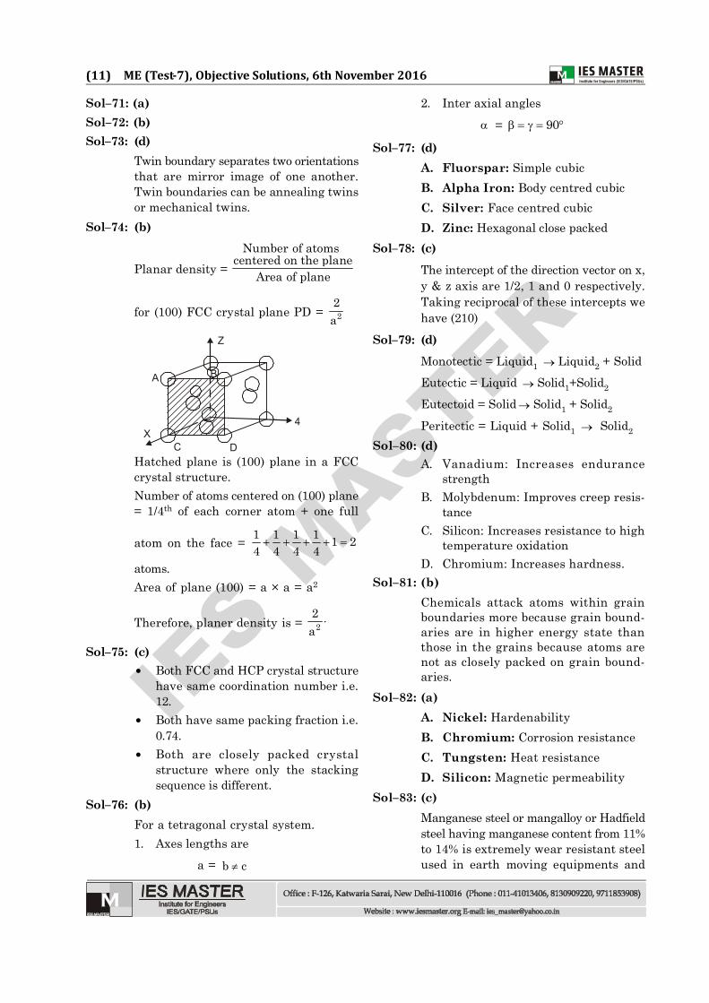
Sol–74: (b)
Planar density =Number of atoms
centered on the planeArea of plane
for (100) FCC crystal plane PD = 22a
Z
A
XC D
B
4
Hatched plane is (100) plane in a FCCcrystal structure.Number of atoms centered on (100) plane= 1/4th of each corner atom + one full
atom on the face = 1 1 1 1 1 24 4 4 4
atoms.Area of plane (100) = a × a = a2
Therefore, planer density is = 22a
Sol–75: (c) Both FCC and HCP crystal structure
have same coordination number i.e.12.
Both have same packing fraction i.e.0.74.
Both are closely packed crystalstructure where only the stackingsequence is different.
Sol–76: (b)For a tetragonal crystal system.1. Axes lengths are
a = b c
2. Inter axial angles = 90
Sol–77: (d)A. Fluorspar: Simple cubicB. Alpha Iron: Body centred cubicC. Silver: Face centred cubicD. Zinc: Hexagonal close packed
Sol–78: (c)The intercept of the direction vector on x,y & z axis are 1/2, 1 and 0 respectively.Taking reciprocal of these intercepts wehave (210)
Sol–79: (d)Monotectic = Liquid1 Liquid2 + SolidEutectic = Liquid Solid1+Solid2
Eutectoid = Solid Solid1 + Solid2
Peritectic = Liquid + Solid1 Solid2
Sol–80: (d)A. Vanadium: Increases endurance
strengthB. Molybdenum: Improves creep resis-
tanceC. Silicon: Increases resistance to high
temperature oxidationD. Chromium: Increases hardness.
Sol–81: (b)Chemicals attack atoms within grainboundaries more because grain bound-aries are in higher energy state thanthose in the grains because atoms arenot as closely packed on grain bound-aries.
Sol–82: (a)A. Nickel: HardenabilityB. Chromium: Corrosion resistanceC. Tungsten: Heat resistanceD. Silicon: Magnetic permeability
Sol–83: (c)Manganese steel or mangalloy or Hadfieldsteel having manganese content from 11%to 14% is extremely wear resistant steelused in earth moving equipments and

IES M
ASTER
(12) ME (Test-7), Objective Solutions, 6th November 2016
mining industry.Sol–84: (b)
Addition of silicon to cast iron promotesgraphite flake formation; it also increasesfluidity of molten metal while castingsilicon forces carbon out of solid solution,this carbon forms graphite flakes.
Sol–85: (d)In full annealing, hypoeutectoid steel isheated above upper critical temperature.At this temperature dislocations move outof the body reducing imperfections,thereby increasing ductility of steel.Cooling is done inside the furnaces. Finalmicrostructure is uniform coarse pearlite.
Sol–86: (c)Air has very low cooling rate followed by,fused salt, oil and water in increasingorder.
Sol–87: (b)• Normalizing refines the grain
structure by producing fine pearlite.• Full annealing gives uniform grain
structure.• Martempering improves toughness of
steel without compromising on itshardness, while ductility decreases.
• Spherodizing heat treatment givesmaximum softness of structure.
Sol–88: (d)Time, temperature, Transformation (TTT)diagrams indicates transformation ofaustenitic phase.
Sol–89: (c)
Let be the mass per unit length of thestring m/ l .
Weight of hanging part = m g mg ll
T = mg ...(i)
For the chain on the table,
T = mN 1 g l
l
= 1 mg ...(ii)
Comparing eqns. (i) and (ii),
1 mg = mg
= 1
Work done when the chain slides downby small distance dx at length x downthe table is given by
dW =mgx dx
l
W = 11 1 2
00 0
mgx mg xFdx dx2
ll l
l l
= 2 221 1 m gmg2 2
l ll
Sol–90: (b)When block C collides elastically withblock A, they simply exchange theirvelocities, i.e., block C comes to rest andblock A gets velocity v just after thecollision.Now the block A moving with velocity vcompresses the spring and the combinedsystem moves with speed v’ (say) at themaximum compression of the spring.
For block A and B:
mv + 0 = (m m)v
v = v/2
Also, 21 mv 02
= 2 2m
1 1m m v kx2 2
21 mv2 =
22m
1 v 12m kx2 4 2
IES M
ASTER
(13) ME (Test-7), Objective Solutions, 6th November 2016
xm = mv2k
K.E. at maximum compression is
K.E. = 2
21 v2m2 2
= 21 mv4
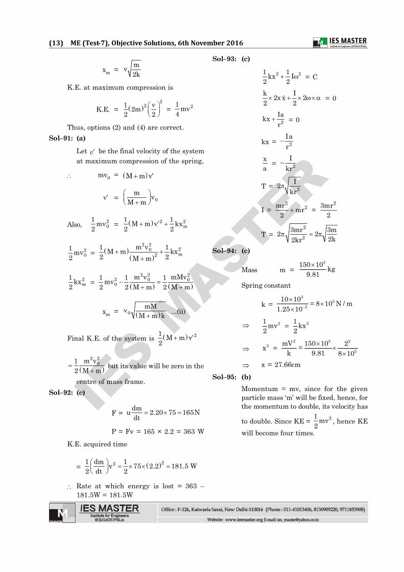
Thus, options (2) and (4) are correct.Sol–91: (a)
Let v be the final velocity of the systemat maximum compression of the spring,
mv0 = M m v
v = 0m v
M m
Also, 20
1 mv2 = 2 2
m1 1M m v kx2 2
20
1 mv2 =
2 220m2
m v1 1M m kx2 2M m
2m
1 kx2 =
2 2 22 0 00
m v mMv1 1 1mv2 2 M m 2 M m
xm = 0mMv
M m k...(ii)
Final K.E. of the system is 21 M m v2
2 20m v1
2 M m
but its value will be zero in the
centre of mass frame.Sol–92: (c)
F = dmu 2.20 75 165Ndt
P = Fv = 165 × 2.2 = 363 WK.E. acquired time
= 221 dm 1v 75 2.2 181.5 W2 dt 2
Rate at which energy is lost = 363 –181.5W = 181.5W
Sol–93: (c)
2 21 1kx I2 2 = C
k I2x x 22 2 = 0
2Iakxr
= 0
kx = 2Iar
xa = 2
Ikr
T = 2I2
kr
I = 2
2mr mr2
= 23mr
2
T = 2
23mr 3m2 2
2k2kr
Sol–94: (c)
Mass m = 3150 10 kg
9.81Spring constant
k = 3
52
10 10 = 8 10 N / m1.25 10
21 mv2 = 21 kx
2
2x =
2 3 2
5mV 150 10 2=
k 9.81 8 10 x = 27.66cm
Sol–95: (b)Momentum = mv, since for the givenparticle mass ‘m’ will be fixed, hence, forthe momentum to double, its velocity has
to double. Since KE = 21 mv2 , hence KE
will become four times.

IES M
ASTER
(14) ME (Test-7), Objective Solutions, 6th November 2016
Sol–96: (b)8 kN
C
RA
A
10 kN
RB
B D
6 m 4 m 5 mRA + RB = 8 + 10 = 18
Moment of forces about A should be zero.Hence, RB × 10 – 8 × 6 – 10 × 15 = 0
RB = 19.8 kN ( )
RA = 1.8 kN ( )
Sol–97: (d)10 kN
10 kN
A6 kN
P
Balancing the forces in vertical directionat point A, we have, the force in memberP of the truss = 6 kN tensile.
Sol–98: (c)Balancing the force at point P,
1
P
8 kNthe force in number (1) will be 8 kNtensile.
Sol–99: (c)
Tdxx
100 NLet the weight per unit length of the rope= N/m.
Then Tension T in the rope at a distance‘x’ from the bottom = x 100 Work done due to tension in the rope forraising by a distance ‘dx’ = Tdx
=
626
0 0
xdx = 100xx 1002
= 36 100 6 18 600=2
= 20 N/m6
Work done = 2018 600 660Nm=6
Sol–100: (d)Average acceleration: v / t
Instantaneous acceleration: t 0
lim v / t
Uniform motion: a = 0Uniformly accelerated motion: a =constant
Sol–101: (a)Acceleration due to gravity will beindependent of the mass hence accelerationfor the two bodies will be same. However,momentum, potential energy, kineticenergy, will be different for differentmasses.
Sol–102: (c)Let the weight of the box be w. Thensince the box moves with constant velocity,so net force on the box will be zero.
F = w
F = 0.4 w
F
H
Aw
wFor the box to overturn, moment about Ashould be zero.Here, w × 30 = F × H w × 30 = 0.4 w×H

IES M
ASTER
(15) ME (Test-7), Objective Solutions, 6th November 2016
H = w 30 30 75 mm= =0.4w 0.4
Sol–103: (d)Angular acceleration
=
Final angular velocityinitial angular velocity
time
= 220 0 5 rad/s=4
Moment of inertia of disc =2
2mr 0.5kgm=2
Torque required = I
= 1 5 2.5Nm=2
Sol–104: (b)V2 = u2 – 2 as
Initial velocity u = 20m/s, final velocity v= 0
Deceleration a = 2g 0.8 10 8m/s= =
0 = 202 – 2 × 8 × s
s = 220 25m=
2 8Sol–105: (c)
Stress induced in the bar due to rise intemperature
= E (Deflection prevented)L
= E (L T 0.02)L
= 6
610 [25 20 10 100 0.02]25
= 1200 = 12×102 kg/cm2
Sol–106: (d)Elongation in bar due to load P
= PLAE
=
2
10 100 4E d
= 2 2 21000 4 1 1 1
E (40) (50) (60)
=40 1 1 1 mmE 16 25 36
Sol–107: (a)
ABC
Deflected shapeof rigid beam
1 m 2 m
x1x2
From similar triangle
1x3 = 2x
2 … (i)
Force in spring at CForce in spring at B = 1 1
2 2
K xK x =
1 32 2 = 3
4
Sol–108: (c)
A
B
C+ 25 kN
ba
RA = b 3LP 25 15 kN (Tension)
a b 2L 3L
RC = a 2LP 25 10 kN (Comp)
a b 2L 3LSol–109: (b)
SFD is zero along the span it shows thatonly couple of opposite nature and equalmagnitude are acting on the member. Nopoint loading or udl is acting any wherein the span.
Sol–110: (c)
dM Vdx
Slope of BMD = Shear forceMoving from C to A at point B slope ofBMD is reduced this shows shear force isreduced means reaction or load at B andC are in opposite direction. Which is thecase only with option (c) hence (c) is thecorrect answer.
Sol–111: (c)
100 kN/mA B
a = 2 m a = 2 m

IES M
ASTER
(16) ME (Test-7), Objective Solutions, 6th November 2016
Maximum hogging moment will occur atsupport A and B.Maximum sagging moment (if saggingmoment is present) will be at mid span ofthe span AB
Maximum hogging moment = 2wa
2
=
2100 2 200 kNm2
Maximum sagging moment = 2 2w wa
8 2l
=
2 2100 8 100 28 2
= 800–200 = 600kNmHence design moment = Max [Hoggingmoment, Sagging moment]= 600 kNm
Sol–112: (b)
10 kN W 10 kN
2 m 2 m4 m
A BC
At support, MA = 10 × 2 = 20 kNm
Given : MA = MC
20 kNm20 kNm
W
4 mw/2w/2
B.M. at mid span
MC = WL 204 =
W 4 20
4= W – 20
20 = W – 20W = 40 kN
Sol–113: (b)4 kN.m
4 m
4 kN.mA B
RA = RB = 4 44 = 0
Using moment area method :
4EI
A BCM diagramEI
At central point C, deflection is C and due tosymmetry, deflection at C is maximum andslope of elastic curve is zero i.e. C = 0Applying moment area equation between pointC & B
B = C C L Ax
0 = C
40 2 1EI
C = 8EI
(–) ve sign shows downward deflection.Alternative :
A B
R = R = 0 BA2 m 2 m
At C slope is zero so part AC can be thoughtas cantilever beam carrying moment M = 4kNm at end A. As reaction at A is zero so itcan be treated as free end.
A C
L
M
A =
2 2ML 4 2 82 EI 2EI EI
which is equal to C in original structure.
Sol–114: (c)
A B
10 kN/mC
A C
RBC
R
4 m 4 m
4 m4 m
Downward deflection of point C in beam AC =Downward deflection of point C in beam CB
4 3w RL
8EI 3EIl =
3RL3EI

IES M
ASTER
(17) ME (Test-7), Objective Solutions, 6th November 2016
4 310 4 R 48 3
= 3R 43
R = 7.5 kN
Sol–115: (a)
Principal strains 1/2
=
2 2x y x y xy
2 2 2
= 6 6800 10 100 10
2
2 26 6 6800 10 100 10 800 102 2
1 = 450 × 10–6 + 531.507 × 10⁻⁶
1 = 981.5 × 10⁻⁶
2 = 450 × 10–6 – 531.507 × 10–6 = –81.5 ×10⁻⁶
Sol–116: (c)
Major principal stress,
1 =
2x y x y 2
xy2 2
=
2240 0 40 80
2 2
= 20 + 82.4621 = 102.462 102.5 MN/m2
Minor principal stress,
3 =
2x y x y 2
xy2 2= 20 – 82.462 –62.5 MN/m2
2 =
xy1
x y
2tan
( ) =
1 2 80tan40
2 = 75.96 = 37.98° 38°
Sol–117: (d)
2
y
y
x
x
( , ) y xy
( , – ) x x y
( , ) y x y
( , ) x xy
0
x y , 02
y-axis
x-axis
x -axis
y -axis
B
D
C
A
Sol–118: (a)
x
A
B
y
xy 0
x y
2 xysin2 cos2
= sin2 0
2 = 0
Option (a) is correct.
Sol–119: (d)
45x =
1 2 1 2 cos(2 45 )2 2
45x60 40 0
2 = 10 N/mm2
Sol–120: (d)
According to max. shear stress theory
FOS =
yf2
Absolute max. shear stress
=
1 2 1 2
2802
p p p pMax. , ,2 2 2

IES M
ASTER
(18) ME (Test-7), Objective Solutions, 6th November 2016
=
140100 40 100 40max , ,
2 2 2
=
140100 40 100 40max , ,
2 2 2
= 14070 = 2
Sol–121: (b)Sol–122: (d)
According to 1st law of thermodynamics,for a cyclic process, Q W=
1
2
Q12 + Q21 = W12 + W21
100 + 120 = 50 + W21
W21 = 170 kJSol–123: (b)
Work output of reversible heatengine (HE1)
W = 1
T Q11000
Similarly, for heat engine(HE2)
1000 KQ 1
Q 2
HE1
HE2
T
Q 2
Q 3
W
W
300 K
W = 2
300 Q1T
Both the engine produce sameamount of work,hence,
1
T Q11000 =
2300 Q1T
T11000 =
2
1
Q3001 QT
Since, 2
1
QQ = T
1000
hence,
T11000 =
1 300
1000T
T 300=
1000 1000
1 + 0.3 = 2T 1.3=1000
T = 1300 650K=2
Sol–124: (b)According to first law of thermodynamics,for a cyclic process,
Q = W
Q12 + Q23 + Q34 + Q41
= W12 + W23 + W34 + W41
220 + (–25) + (–180) + 50= 15 + (–10) + 60 + W41
WA1 = (220 – 25 – 180 + 50–15 + 10 – 60) = 0
Sol–125: (c)Work transfer in free expansion is zero,because in free expansion, the pressureagainst which the gas expands is zero.Hence, work = P V 0 .
Sol–126: (a)For steady flow process,
h1 + Q = h2 + W Q = (h2 – h1) + W Q = 30 + (–90) = –60kJ/kg Total heat lost = 60 kJ/kg Heat lost to circulating cooling
water = 40 kJ/kg Heat lost to atmosphere = 60 – 40 =
20 kJ/kgSol–127: (a)
V
P3
41
2
S = C
Otto cycle
S = C
V
P1
2
34
T = C
Stirling cycle
T = C
IES M
ASTER
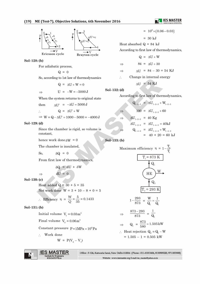
(19) ME (Test-7), Objective Solutions, 6th November 2016
P
Ericsson cycleV
1
23
4
T = CT = C
2 3
1 4V
P
pV =c
pV =c
Brayton cycle
Sol–128: (b)For adiabatic process,
Q = 0So, according to 1st law of thermodynamics
Q = U W 0=
U = W 5000 J=
When the system returns to original state
then U = U 5000J
Q = U W
W Q U 1000 5000 4000J= =
Sol–129: (d)Since the chamber is rigid, so volume isconstant,
hence work done W = 0
The chamber is insulated,
So, Q = 0
From first law of thermodynamics,
Q = dU + W
dU = 0Sol–130: (c)
Heat added Q = 30 + 5 = 35Net work done W = 3 + 10 – 8 + 0 = 5
Efficiency = 5 0.1433= =35WQ
Sol–131: (b)
Initial volume 31V 0.03m=
Final volume 32V 0.06m=
Constant pressure 6P 1MPa 10 Pa=
Work doneW = P(V2 – V1)
= 610 0.06 0.03
= 30 kJHeat absorbed Q = 84 kJAccording to first law of thermodynamics,
Q = U W
84 = U 30
U = 84 – 30 = 54 KJ
Change in internal energy
U = 54 KJ
Sol–132: (d)According to first law of thermodynamics,
1 2 3Q = 1 2 3 1 2 3U W
100 = 1 2 3U 60
1 2 3U = 40 Kg
1 2 3U = 1 4 3U 40kJ
1 4 3Q = 1 4 3 1 4 3U W
= 40 + 20 = 60 kJSol–133: (b)
Maximum efficiency = 2
1
T1T
T 1
HE
T 2 = 293 K
= 873 KQ 1
W
Q 2
2931873
= 1 1
W 1Q Q
873 293
873
= 1Q
1Q = 873 1.505kW580
Heat rejection 2 1Q Q W=
= 1.505 – 1 = 0.505 kW

IES M
ASTER
(20) ME (Test-7), Objective Solutions, 6th November 2016
Sol–134: (b)Work done = area under the graph
= 12 × (10 + 5) × 1 + 5 × 2 = 17.5J
U = 2.5 J
Q = U + W = 2.5 + 17.5 = 20JSol–135: (d)
Pure substance, number of components,C = 1
Degree of freedom from Gibb’s phase rule, DOF = C – + 2In saturated vapour, number of phases,
= 1DOF = 1 – 1 + 2 = 2
For superheated vapour, number of phases, = 1
DOF = 1 – 1 + 2 = 2Sol–136: (d)
P
VV /21 V1
2 1
SaturatedVapour Curve
Isothermalcurve
Since at time of compression, the workingmedium is saturated vapour (point 1). Itis known that slope of saturation curve ismore than the isothermal compression. Soas soon as compression starts thecompressed fluid comes in two phaseregion and condensation at constantpressure and temperature starts and somevapour condenses and pressure andtemperture do not change.
Sol–137: (a)At 4°C, the density of water startsreducing due to hydrogen bond formation.Before 4°C, the water inside of lake is hotand light while at surface it is cooled andheavy. So natural circulation starts and
cold and hot water mixed up. But below4°C, water and then ice is lighter thannormal water, so it floats at surface.
Sol–138: (d)
The normal drinking water is not a puresubstance because it contains solidcontaminants. But at the same time ifwater is distilled one, it will be pure.
Sol–139:(b)If a machine would continuously pro-duce net work without expenditure ofsome other form of energy, then such aheat engine is called perpetual motionmachine of the second kind (PMM2). APMM2 is impossible. It violates secondlaw of thermodynamics. The efficiencyof a heat engine can never be 100%.There has to be a heat rejection always.
Sol–140: (a)Sol–141: (d)Sol–142: (d)Sol–143: (d)
Most of the materials exist inpolycrystalline form and not as singlecrystal. In poly crystalline materialindividual crystals have differentorientations. There are some materials,which exist in form of single crystals suchas rock salt, sugar etc.
Sol–144: (c)Cast Iron is hard, brittle and wear re-sistant. Cast Iron contains more than2% carbon and percentage of cementitein it is higher.
Sol–145: (a)
Sol–146. (a)Shear is maximum at 45° to the directionof the applied tensile force and mild steelis weak in shear so failure takes place inthe direction of maximum shear stress,in cup and cone shape fracture.

IES M
ASTER
(21) ME (Test-7), Objective Solutions, 6th November 2016
Sol–147: (c)
Assertion is correct but reason is wrong
because dMdx = F = 0 is applicable for load
intensity, not concentrated load because
due to concentrated load dMdx is not
depended mathematically.
PL/4 WL /82
Sol–148: (a)
q
AB
CD
q
q
q
q
q q
A B
C D
q
q
q q
A
C D
q
q
q
q
q B
(a) (b) (c)When an element is in a state of pure shear,maximum direct stresses are induced onmutually perpendicular planes which are 45ºto planes of pure shear. One of the maximumdirect stresses is tensile. So block will generatecracks along this if these stress increases andother maximum direct stress is compressive sofailure may occur due to crushing in this case.
Sol–149: (c)Cam and follower is a higher pair becausethere is point or line contact between thecam and the follower. Surface contacttakes place between two links of a lowerpair.
Sol–150: (a)Number of degrees of freedom
n = 3 2j h1
Here, = 4, j = 4, h = 0 n = 3(4 – 1) – 2 × 4 – 0
= 9 – 8 – 0 = 1Hence, the mechanism has single degreeof freedom and the overall movability ofthe mechanism is unity.
Sol–151: (c)Inversion is obtained by fixing, in turn,different links in a kinematic chain andwe can obtain as many mechanisms asthe links in a kinematic chain. Forexample, four inversions of a single slidercrank chain are possible.
Connectingrod
Cutting strokeReturn stroke
Ram ToolR2
R1R
Line ofstroke
P2
QP1
B
Slider (Link 1) Crank (Link 2)
Fixed(Link 3)
C
B2B1
Slotted bar(Link 4)
A
902
Fig. Crank and slotted level quick returnmotion mechanism.
In crank and slotted lever quick returnmotion mechanism, the link AC i.e. link3 forming the turning pair is fixed. Thelink 3 corresponds to the connecting rodof a reciprocating steam engine.
Sol–152: (d)Ackermann steering gear is preferred toDavis steering gear because it consists ofturning pairs, hence less friction and soless wear and tear.
Sol–153: (b)In hot working, the material is abovethe recrystallisation temperature, henceit is possible to continuously reform thegrains in metal working and if thetemperature and the conditions ofworking are properly controlled, a veryfavourable grain size could be achievedgiving rise to better mechanical

IES M
ASTER
(22) ME (Test-7), Objective Solutions, 6th November 2016
properties.Sol–154:(a)Sol–155: (d)
It is important to make sure that thesprue does not act as the choke. This isbecause a condition can be generated inwhich iron can leave the gating systemfaster than it can be poured into thepouring basin. So avoid this, at least asmuch liquid must be capable of passingthrough the sprue as through all thegates. This can be expressed mathematicallyusing the equation for the rate of fillingderived using the Toricelli’s equation. Thevelocity of liquid flow through the top ofthe sprue is given by the equation,
Vs = C 2ghwhere C is a friction factor
The rate of flow Q = sA C 2gh , whereAs is the cross-sectional area of thesprue.The sharp change in direction from thesprue to runner causes the formationof a stationary liquid pool soon afterpouring has started. This diverts theliquid flow into the runner. The reducedpressure in the region can lead to aspi-ration, thus drawing air into thestream. This air can increase turbu-lence further down the stream causingslag to mix with liquid iron rather thansticking to the top of the runner. A cor-rectly designed runner and gating sys-tem should prevent slag and dross fromentering the mould cavity. In this con-nection, gating ratio is the relationshipbetween the cross-sectional area of thesprue, runner and gate. For example, aratio of 1:2:4 describes a non-pressurisedor sprue/runner - controlled system,whereas a ratio of 1:1:0.7 describes apressurised or runner/gate-controlledsystem. Runner/gate control is used forslag forming irons such as malleableand flake irons. Sprue/runner controlis used for spheroidal irons. Further, asprue/runner control produces a higheryield when a large number of small
castings are in one mould. Runner/gatecontrol is more suitable and produces abetter yield with heavy castings withonly a few in a mould.
Sol–156:(b)Hot chamber die casting uses mainlylow melting point metals.
Sol–157: (a)Electric drives are widely used as theyare clean and quiet with a high degree ofaccuracy and reliability.
Sol–158: (a)In automation, the machine produces ajob following a set operational sequence,while a robot can be made to do differentjobs at different times and in differentsequences through programming. Anautomated machine has neither aknowledge base nor intelligence, likerobot. So, robot is more than anautomated machine/equipment.
Sol–159: (a)A robotic manipulator arm consists ofseveral separate links making a chain(simple open chain formed by linksconnected in series). The arm is locatedrelative to the ground on either a fixedbase or a movable base. It has a free-endwhere an end-deflector or gripper orsometimes a specialised tool holder or anypowered device is attached.
Sol–160: (a)The load carrying capacity of a robotdepends on its physical size andconstruction, so that is why, very lightmodels have capacity as low as 1.5 kg,while the heavier class of robots have theircapacities as high as 1000 kg.