ansi z80.1-200? project group draft z80.1... · ansi z80.1-200? 1 project group draft . ken wood,...
TRANSCRIPT

ANSI Z80.1-200?
1
PROJECT GROUP DRAFT Ken Wood, December 12, 2002
ANSI Z80.1- 200? Revision of ANSI Z80.1 — 1999 American National Standard for Ophthalmics Prescription Ophthalmic Lenses Secretariat
Optical Laboratories Association Approved
American National Standards Institute, Inc.
ANSI Z80.1-200?
2
Contents
1 Scope and Purpose............................................................................................................... 3
2 References............................................................................................................................ 4
3 Definitions ............................................................................................................................. 5
4 Optical Requirements.......................................................................................................... 13
5 Mechanical Requirements................................................................................................... 17
6 Transmittance & Attenuation Requirements ....................................................................... 18
7 Test Methods ...................................................................................................................... 19
8 Identification........................................................................................................................ 27
Annexes
A Technical Addendum to Impact Testing ............................................................................. 28 B The Boxing System of Measurement ................................................................................. 33 C Typical Layout of Progressive Lenses................................................................................ 35 D Reference Method for Evaluating Progressive Addition Lens Characteristics ................... 36 F Optical Tolerances………………………………………………………………………………...38
G Mechanical and Transmittance Tolerances……………………………………………………39
E Bibliography........................................................................................................................ 40
ANSI Z80.1-200?
3
AMERICAN NATIONAL STANDARD ANSI Z80.1-200X
American National Standard for Ophthalmics
Prescription Ophthalmic Lenses
1 Scope and Purpose
1.1 Scope This standard applies to the processing of all prescription ophthalmic spectacle lenses in edged or assembled form. It is a processing guideline for optical laboratories applicable to prescription eyewear prior to transfer for dispensing, and for the dispenser prior to the delivery of the finished eyewear to the patient. Relevant optical specifications and tolerances of this standard should apply also to uncut lenses supplied by an optical laboratory to be used in filling a specific prescription.
This standard does not apply to products covered by American National Standard Requirements for Nonprescription Sunglasses and Fashion Eyewear, ANSI Z80.3-1996.
1.2 Purpose
This standard reflects the shift in utilization from mass-produced lenses to a basic dependence upon custom-processed lenses at the laboratory level. It does not represent tolerances that describe the state-of-the-art of the ophthalmic laboratory, but provides quality goals for new pristine lenses prepared to individual prescription. The individual performance parameters listed in this standard can be achieved reliably. However, it is difficult to meet all of the requirements simultaneously in any given lens or mounted pair. The fact that, under rigorous application of this standard, a significant number of spectacles (approximately 25%, based upon industry data) will not achieve all parameters simultaneously, must be accepted as a reflection of the state-of-the-art (see Informative Reference). As such, this standard expresses desirable technical concepts that provide a frame of reference for safety and effectiveness and is not designed as a regulatory instrument.
ANSI Z80.1-200?
4
2 References
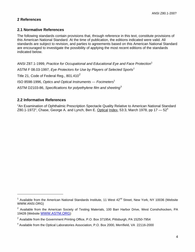
2.1 Normative References The following standards contain provisions that, through reference in this text, constitute provisions of this American National Standard. At the time of publication, the editions indicated were valid. All standards are subject to revision, and parties to agreements based on this American National Standard are encouraged to investigate the possibility of applying the most recent editions of the standards indicated below.
ANSI Z87.1-1999, Practice for Occupational and Educational Eye and Face Protection1
ASTM F 08.03-1997, Eye Protectors for Use by Players of Selected Sports1
Title 21, Code of Federal Reg., 801.4102
ISO 8598-1996, Optics and Optical Instruments — Focimeters1
ASTM D2103-86, Specifications for polyethylene film and sheeting3
2.2 Informative References "An Examination of Ophthalmic Prescription Spectacle Quality Relative to American National Standard Z80.1-1972", Chase, George A. and Lynch, Ben E. Optical Index, 53:3, March 1978, pp 17 — 524
1 Available from the American National Standards Institute, 11 West 42nd Street, New York, NY 10036 (Website WWW.ANSI.ORG) 2 Available from the American Society of Testing Materials, 100 Barr Harbor Drive, West Conshohocken, PA 19428 (Website WWW.ASTM.ORG) 2 Available from the Government Printing Office, P.O. Box 371954, Pittsburgh, PA 15250-7954 4 Available from the Optical Laboratories Association, P.O. Box 2000, Merrifield, VA 22116-2000
ANSI Z80.1-200?
5
3 Definitions
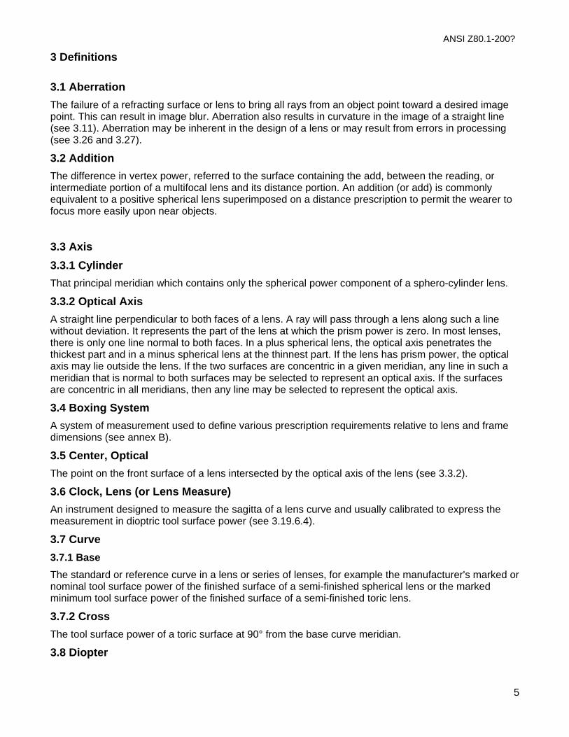
3.1 Aberration The failure of a refracting surface or lens to bring all rays from an object point toward a desired image point. This can result in image blur. Aberration also results in curvature in the image of a straight line (see 3.11). Aberration may be inherent in the design of a lens or may result from errors in processing (see 3.26 and 3.27).
3.2 Addition The difference in vertex power, referred to the surface containing the add, between the reading, or intermediate portion of a multifocal lens and its distance portion. An addition (or add) is commonly equivalent to a positive spherical lens superimposed on a distance prescription to permit the wearer to focus more easily upon near objects.
3.3 Axis 3.3.1 Cylinder That principal meridian which contains only the spherical power component of a sphero-cylinder lens.
3.3.2 Optical Axis A straight line perpendicular to both faces of a lens. A ray will pass through a lens along such a line without deviation. It represents the part of the lens at which the prism power is zero. In most lenses, there is only one line normal to both faces. In a plus spherical lens, the optical axis penetrates the thickest part and in a minus spherical lens at the thinnest part. If the lens has prism power, the optical axis may lie outside the lens. If the two surfaces are concentric in a given meridian, any line in such a meridian that is normal to both surfaces may be selected to represent an optical axis. If the surfaces are concentric in all meridians, then any line may be selected to represent the optical axis.
3.4 Boxing System
A system of measurement used to define various prescription requirements relative to lens and frame dimensions (see annex B).
3.5 Center, Optical The point on the front surface of a lens intersected by the optical axis of the lens (see 3.3.2).
3.6 Clock, Lens (or Lens Measure) An instrument designed to measure the sagitta of a lens curve and usually calibrated to express the measurement in dioptric tool surface power (see 3.19.6.4).
3.7 Curve
3.7.1 Base The standard or reference curve in a lens or series of lenses, for example the manufacturer's marked or nominal tool surface power of the finished surface of a semi-finished spherical lens or the marked minimum tool surface power of the finished surface of a semi-finished toric lens.
3.7.2 Cross
The tool surface power of a toric surface at 90° from the base curve meridian.
3.8 Diopter
ANSI Z80.1-200?
A unit of measurement in inverse meters (plus or minus) used to express the power of a lens. The diopter is also used to express the curvature of surfacing tools and the refracting power of curved surfaces (see 3.19.6.3, 3.19.6.4, and 3.19.7). The symbol ‘D’ is used to designate the diopter.
3.9 Diopter, prism
A unit of measurement used to express the angle of deviation of a ray of light by a prism or lens. Prism power, in these units, is measured as the displacement of the ray, in centimeters, perpendicular to its line of incidence at a distance of one meter. The symbol Δ is used to designate the prism diopter.
3.10 Dispersion
Dispersion is a measure of the ability of a material to refract light into its various component wavelengths. Reciprocal relative dispersion is used in optical design calculations. It is also called the nu value or the Abbe value and is defined by the following formula:
νηη ηd
d
F C=
−−
1
where:
νd is the relative reciprocal dispersion using the helium d-line as the reference wavelength;
ηd is the index of refraction for radiation of wavelength 587.5618 nm (helium d-line);
ηF is the index of refraction for radiation of wavelength 486.1327 nm (hydrogen F-line);
ηC is the index of refraction for radiation of wavelength 656.2725 nm (hydrogen C-line)
In the US, the reference wavelength used is 587.5618 nm.
3.11 Distortion An aberration that results in straight lines being imaged as curves.
3.12 Focimeter
An instrument for determining vertex power, cylinder axis location, optical center and prism reference point location and prism power at a given point on an ophthalmic lens.
3.13 Index of Refraction
The ratio of the velocity of light of a given wavelength in air to that in a medium. This ratio expresses the ability of a lens material to refract or bend a ray of light. The index of refraction is given for a specified reference wavelength (see 3.22).
3.14 Intermediate
That area in a trifocal lens or progressive lens which has been designated to correct vision at ranges intermediate to distant and near objects.
3.15 Interpupillary Distance
3.15.1 Distance, Binocular The separation between the visual axes of the eyes in their primary position, as the subject fixates on an infinitely distant object. This distance is measured from pupil to pupil.
3.15.2 Near, Binocular The separation between the visual axes of the eyes, at the plane of the spectacle lenses, as the subject fixates on a near object at the intended working distance.
6

ANSI Z80.1-200?
7
Note: This distance is conventionally 40 cm from the spectacle plane for add powers equal to or less than 2.50 D. For higher adds, this distance (expressed in meters) is the reciprocal of the add power.
3.15.3 Monocular The separation between the center of the bridge of the nose and the visual axis of the designated eye (i.e., right or left) for either distance or near fixation. The right and left interpupillary distances may not necessarily be equal. Their sum is equal to the binocular interpupillary distance. When the monocular interpupillary distance is not specified, it is assumed to be one half of the binocular interpupillary distance.
3.16 Lens(es) 3.16.1 Aspheric A lens in which one or both surfaces are aspheric (see 3.24.1).
3.16.2 Assembled A lens or lenses that has (have) been combined with a frame or mounting.
3.16.3 Cylinder
A special case of the sphero-cylinder lens in which one of the principal meridians has zero refractive power (see 3.16.19).
3.16.4 Edged A lens whose periphery has been ground (flat, rimless, grooved, or beveled) to a specified size and shape.
3.16.5 Finished A lens with both surfaces optically finished.
3.16.6 Impact-Resistant Lenses for Dress Eyewear Lenses that conform to the detailed requirements for impact resistance in 6.6. Dress (or street-wear) lenses are not to be confused with special-purpose occupational, educational, or recreational protective lenses.
3.16.7 Impact-Resistant Lenses for Occupational and Educational Protection Lenses that conform to the requirements of the most recent edition of ANSI Z87.1-1999.
3.16.8 Iseikonic A type of lens made with special thickness, surface curvatures, and bevel edge location to control the magnification of an image while maintaining the prescribed refractive power.
3.16.9 Laminated A lens constructed as a sandwich of multiple layers of glass, plastic, or both, bonded together as a single unit.
3.16.10 Lenticular A lens, usually of strong refractive power, in which the prescribed power is provided over only a limited central region of the lens, called the lenticular portion. The remainder of the lens is called the carrier and provides no refractive correction but gives dimension to the lens for mounting.
3.16.11 Minus

ANSI Z80.1-200?
8
A lens having negative refractive power. It is thinner at the center than at the edge and causes the divergence of a parallel beam of light.
3.16.11.1 Mounted Pair Two finished lenses of any type mounted in a frame to create complete spectacles.
3.16.12 Multifocal A lens designed to provide correction for two or more discrete distances.
3.16.12.1 Bifocal A lens designed to provide correction for two discrete distances.
3.16.12.2 Trifocal A lens designed to provide correction for three discrete viewing distances.
3.16.13 Plano A lens having essentially zero refractive power.
3.16.14 Plus A lens having positive refractive power. It is thicker at the center than at the edge and causes the convergence of a parallel beam of light.
3.16.15 Progressive A lens designed to provide correction for more than one viewing distance in which the power changes continuously rather than discretely.
3.16.16 Semi-finished A lens having only one surface finished to a specific curve.
3.16.17 Single Vision A lens designed to provide correction for a single viewing distance.
3.16.18 Spherical Power A lens that has the same refractive power in all meridians.
3.16.19 Sphero-cylinder
A lens having different refractive power in the two principal meridians. It is sometimes referred to as an astigmatic or toric lens or, commonly though imprecisely, as a cylinder lens (see 3.16.4).
3.16.20 Ultraviolet Absorption A lens in which the average transmittance between 290 nm and 315 nm (UVΒ) and the average transmittance between 315 nm and 380 nm (UVΑ) is specified.
3.16.21 Uncut A lens with finished optical surfaces on both sides but which has not yet been edged for mounting in a frame.
3.17 Meridian A line of intersection of a surface with a plane perpendicular to that surface at a specified point. When applied to a lens, it may also be defined as a plane that contains the optical axis.
3.18 Meridians, principal
ANSI Z80.1-200?
The two mutually perpendicular meridians in a sphero-cylinder lens in which a maximum and minimum power can be measured.
3.19 Power 3.19.1 Cylinder The difference (plus or minus) between powers measured in the two principal meridians of a sphero-cylinder lens.
3.19.2 Prism The ability of a prism or a lens to deviate a ray of light transmitted through it. It is the deviation of a ray normal to the back surface of a lens and penetrating the front surface at a specified point. The amount of deviation is expressed in prism diopter units. A prism may be specified in terms of its horizontal and vertical components. For example, a 2.83 prism diopter prism base down at 45° O.D. is equivalent to 2.0 prism diopters base-down and 2.0 prism diopters base-out O.D. When prism power is measured with a focimeter, the ray involved is normal to the back surface and coincides with the axis of the focimeter. It is specified in terms of the point on the front surface which it penetrates.
3.19.3 Refractive The ability of a lens or optical surface to produce a change in the convergence or divergence of a beam of light, usually expressed in diopters.
3.19.4 Sphere In a spherical lens, the dioptric power of a lens. In a sphero-cylinder lens, the sphere power is located in the cylinder axis meridian.
3.19.5 Surface 3.19.5.1 Marked The nominal or marked curve of a semi-finished lens indicated in diopters, as expressed by the manufacturer (see 3.7.1).
3.19.5.2 Nominal See 3.19.6.1
3.19.5.3 Refractive The refractive power (FR) of a glass or plastic surface bounded by air is a measure of its ability to change the vergence of a beam of incident light and is defined as follows:
F FrR
dT
d=−
=−η η1
05301
0 001. .
where: ηd is the index of refraction of the material using the helium d-line as the reference wavelength;
r is the radius of curvature of the refracting surface in millimeters;
FT is the tool power defined in 3.19.6.4
Since common ophthalmic materials do not have indices of refraction equal to 1.530, there is not a one-to-one correspondence between surface tool power and surface refractive power. For example, common ophthalmic glass has an index of refraction of ηd = 1.523. Therefore, a 1-diopter surface tool power (FT) will produce a surface refractive power (FR) of 0.987 diopter.
9

ANSI Z80.1-200?
3.19.5.4 Tool (or True Power) By common usage in the United States, a tool with a radius of curvature of 530 mm will produce a surface tool power (FT) of 1 diopter.
Tool power is defined as follows:
FrT =
530
where:
r is the actual radius of curvature in millimeters (mm) for the surface it produces.
Tool power is positive when the surface is convex, negative when concave. The term “surface power” when unqualified refers to tool power. If it is clear from the context that it refers to the true power of a surface, the term “surface power” may be used to discriminate between true power of a surface (see 3.19.5.3) and the vertex power of a lens (see 3.19.6).
3.19.6 Vertex The inverse of the distance, expressed in meters, from the lens vertex to the corresponding focal point. This is expressed in diopters. In a distance prescription, the spherical component of power and the cylindrical component of power are always expressed in terms of rear (or back) vertex power. The reading prescription is expressed in front vertex power. Focimeters are designed to measure vertex power directly.
3.20 Prism, Slab-off A prismatic, component incorporated by bicentric grinding or molding into a portion of an ophthalmic lens to modify the amount of vertical prism for a line of sight through that portion of the lens.
3.21 Reference Point 3.21.1 Distance Reference Point (DRP) That point on a lens as specified by the manufacturer at which the distance sphere power, cylinder power and axis shall be measured.
3.21.2 Fitting Point or Fitting Cross That point on a lens specified by the manufacturer which is used as a reference point for positioning the lens in front of a patient’s eye.
3.21.3 Near Reference Point (NRP) That point on a lens as specified by the manufacturer at which the addition of power is measured.
3.21.4 Prism Reference Point (PRP) That point on a lens as specified by the manufacturer at which the prism value of the finished lens is to be measured.
Unless otherwise specified the prism reference point is assumed to be at the following geometric locations on the lens. For uncut single vision lenses this point is the geometric center of the lens. For uncut multifocal lenses this point is referenced to the segment and is located vertically at the DRP Above Seg Line and horizontally at a distance from the segment center line equal to half the distance PD minus half the near PD (seg inset) (see Figure B.1). For edged single vision and multifocal lenses this point is at the DRP of the lens (see Figure B.1). For progressive lenses this point is specified by the manufacturer.
For non-aspheric single vision and multifocal lenses, the prism reference point and distance reference point are assumed to be coincident.
10
ANSI Z80.1-200?
11
3.22 Reference Wavelength The wavelength of light used when specifying the optical properties and power of a lens.
Note: The reference wavelength used in the United States and in this standard is the helium d-line (587.5618 nm).
3.23 Segment A specified area of a multifocal lens having a different refractive power from the distance portion. This may also refer to the actual piece of material added to the lens in the case of a fused or cemented multifocal lens.
3.231 Spectacles
3.24 Surface 3.24.1 Aspheric A non-spherical surface which is rotationally symmetrical with respect to an axis of symmetry. Such surfaces typically have continuously variable curvatures from the vertex to the periphery.
3.24.2 Plano A flat surface having zero surface power, or an infinite radius of curvature.
3.24.3 Spherical A curved surface having the same radius of curvature in all meridians.
3.24.4 Toric A surface in the form of a torus having different powers in the two principal meridians. The shape may be visualized as a small part of the surface of a doughnut or of a football. A toric surface is generated by rotating an arc of a circle around an axis which does not pass through the center of the circle.
3.25 Thickness, Center The thickness of a lens at the prism reference point.
3.26 Warpage A lens defect in which a surfaced lens is bent or twisted in processing or mounting.
3.27 Wave A local ripple-like irregularity in a lens surface (see 3.11).
ANSI Z80.1-200?
12
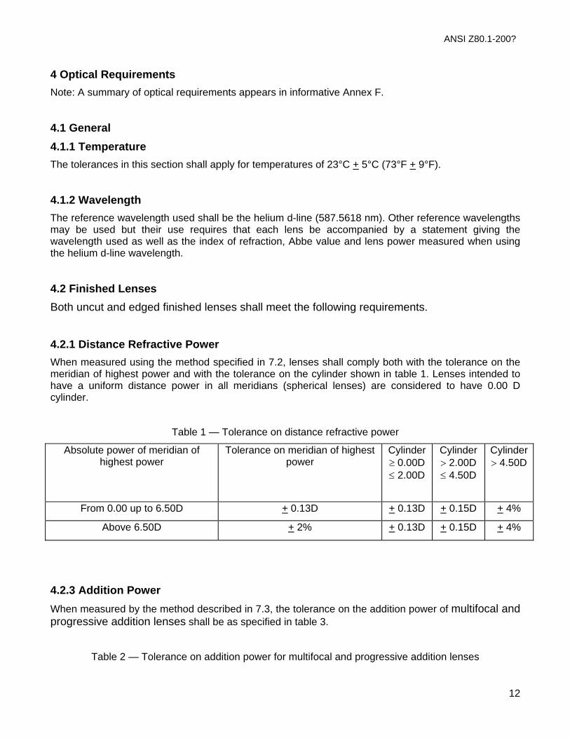
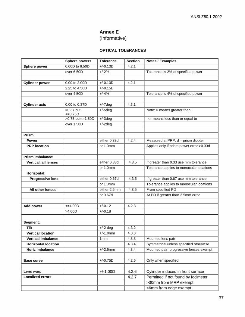
4 Optical Requirements Note: A summary of optical requirements appears in informative Annex F.
4.1 General 4.1.1 Temperature The tolerances in this section shall apply for temperatures of 23°C + 5°C (73°F + 9°F).
4.1.2 Wavelength The reference wavelength used shall be the helium d-line (587.5618 nm). Other reference wavelengths may be used but their use requires that each lens be accompanied by a statement giving the wavelength used as well as the index of refraction, Abbe value and lens power measured when using the helium d-line wavelength.
4.2 Finished Lenses Both uncut and edged finished lenses shall meet the following requirements.
4.2.1 Distance Refractive Power When measured using the method specified in 7.2, lenses shall comply both with the tolerance on the meridian of highest power and with the tolerance on the cylinder shown in table 1. Lenses intended to have a uniform distance power in all meridians (spherical lenses) are considered to have 0.00 D cylinder.
Table 1 — Tolerance on distance refractive power
Absolute power of meridian of highest power
Tolerance on meridian of highest power
Cylinder ≥ 0.00D ≤ 2.00D
Cylinder> 2.00D≤ 4.50D
Cylinder> 4.50D
From 0.00 up to 6.50D + 0.13D + 0.13D + 0.15D + 4%
Above 6.50D + 2% + 0.13D + 0.15D + 4%
4.2.3 Addition Power When measured by the method described in 7.3, the tolerance on the addition power of multifocal and progressive addition lenses shall be as specified in table 3.
Table 2 — Tolerance on addition power for multifocal and progressive addition lenses
ANSI Z80.1-200?
13
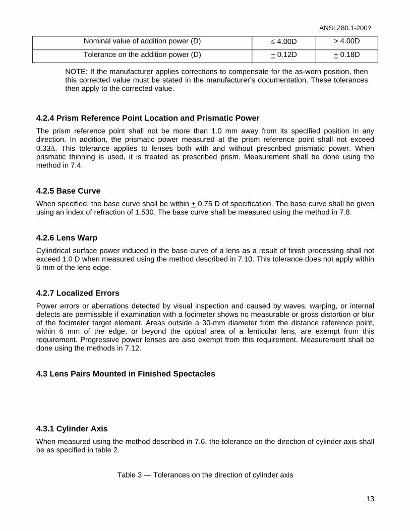
Nominal value of addition power (D) ≤ 4.00D > 4.00D
Tolerance on the addition power (D) + 0.12D + 0.18D
NOTE: If the manufacturer applies corrections to compensate for the as-worn position, then this corrected value must be stated in the manufacturer’s documentation. These tolerances then apply to the corrected value.
4.2.4 Prism Reference Point Location and Prismatic Power The prism reference point shall not be more than 1.0 mm away from its specified position in any direction. In addition, the prismatic power measured at the prism reference point shall not exceed 0.33Δ. This tolerance applies to lenses both with and without prescribed prismatic power. When prismatic thinning is used, it is treated as prescribed prism. Measurement shall be done using the method in 7.4.
4.2.5 Base Curve When specified, the base curve shall be within + 0.75 D of specification. The base curve shall be given using an index of refraction of 1.530. The base curve shall be measured using the method in 7.8.
4.2.6 Lens Warp Cylindrical surface power induced in the base curve of a lens as a result of finish processing shall not exceed 1.0 D when measured using the method described in 7.10. This tolerance does not apply within 6 mm of the lens edge.
4.2.7 Localized Errors Power errors or aberrations detected by visual inspection and caused by waves, warping, or internal defects are permissible if examination with a focimeter shows no measurable or gross distortion or blur of the focimeter target element. Areas outside a 30-mm diameter from the distance reference point, within 6 mm of the edge, or beyond the optical area of a lenticular lens, are exempt from this requirement. Progressive power lenses are also exempt from this requirement. Measurement shall be done using the methods in 7.12.
4.3 Lens Pairs Mounted in Finished Spectacles
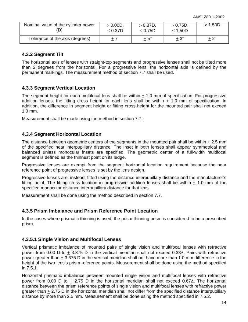
4.3.1 Cylinder Axis When measured using the method described in 7.6, the tolerance on the direction of cylinder axis shall be as specified in table 2.
Table 3 — Tolerances on the direction of cylinder axis
ANSI Z80.1-200?
14
Nominal value of the cylinder power (D)
> 0.00D, ≤ 0.37D
> 0.37D, ≤ 0.75D
> 0.75D, ≤ 1.50D
> 1.50D
Tolerance of the axis (degrees) + 7° + 5° + 3° + 2°
4.3.2 Segment Tilt The horizontal axis of lenses with straight-top segments and progressive lenses shall not be tilted more than 2 degrees from the horizontal. For a progressive lens, the horizontal axis is defined by the permanent markings. The measurement method of section 7.7 shall be used.
4.3.3 Segment Vertical Location The segment height for each multifocal lens shall be within + 1.0 mm of specification. For progressive addition lenses, the fitting cross height for each lens shall be within + 1.0 mm of specification. In addition, the difference in segment height or fitting cross height for the mounted pair shall not exceed 1.0 mm.
Measurement shall be made using the method in section 7.7.
4.3.4 Segment Horizontal Location The distance between geometric centers of the segments in the mounted pair shall be within + 2.5 mm of the specified near interpupillary distance. The inset in both lenses shall appear symmetrical and balanced unless monocular insets are specified. The geometric center of a full-width multifocal segment is defined as the thinnest point on its ledge.
Progressive lenses are exempt from the segment horizontal location requirement because the near reference point of progressive lenses is set by the lens design.
Progressive lenses are, instead, fitted using the distance interpupillary distance and the manufacturer’s fitting point. The fitting cross location in progressive addition lenses shall be within + 1.0 mm of the specified monocular distance interpupillary distance for that lens.
Measurement shall be done using the method described in section 7.7.
4.3.5 Prism Imbalance and Prism Reference Point Location In the cases where prismatic thinning is used, the prism thinning prism is considered to be a prescribed prism.
4.3.5.1 Single Vision and Multifocal Lenses
Vertical prismatic imbalance of mounted pairs of single vision and multifocal lenses with refractive power from 0.00 D to + 3.375 D in the vertical meridian shall not exceed 0.33Δ. Pairs with refractive power greater than + 3.375 D in the vertical meridian shall not have more than 1.0 mm difference in the height of the two lens’s prism reference points. Measurement shall be done using the method specified in 7.5.1.
Horizontal prismatic imbalance between mounted single vision and multifocal lenses with refractive power from 0.00 D to + 2.75 D in the horizontal meridian shall not exceed 0.67Δ. The horizontal distance between the prism reference points of single vision and multifocal lenses with refractive power greater than + 2.75 D in the horizontal meridian shall not differ from the specified distance interpupillary distance by more than 2.5 mm. Measurement shall be done using the method specified in 7.5.2.
ANSI Z80.1-200?
15
4.3.5.2 Progressive Lenses
Vertical prismatic imbalance of mounted pairs of progressive addition lenses with refractive power from 0.00 D to + 3.375 D in the vertical meridian shall not exceed 0.33Δ. Pairs with refractive power greater than + 3.375 D in the vertical meridian shall not have more than 1.0 mm difference in the height of the two lens’s prism reference points. Measurement shall be done using the method specified in 7.5.3.
Horizontal prismatic imbalance between progressive lenses with refractive power from 0.00 D to + 3.375 D in the horizontal meridian shall not exceed 0.67Δ. For lenses with greater refractive power, the horizontal position of each lens’s prism reference point shall not differ from the specified position by more than 1.0 mm. Measurement shall be done using the method specified in 7.5.3.

ANSI Z80.1-200?
16
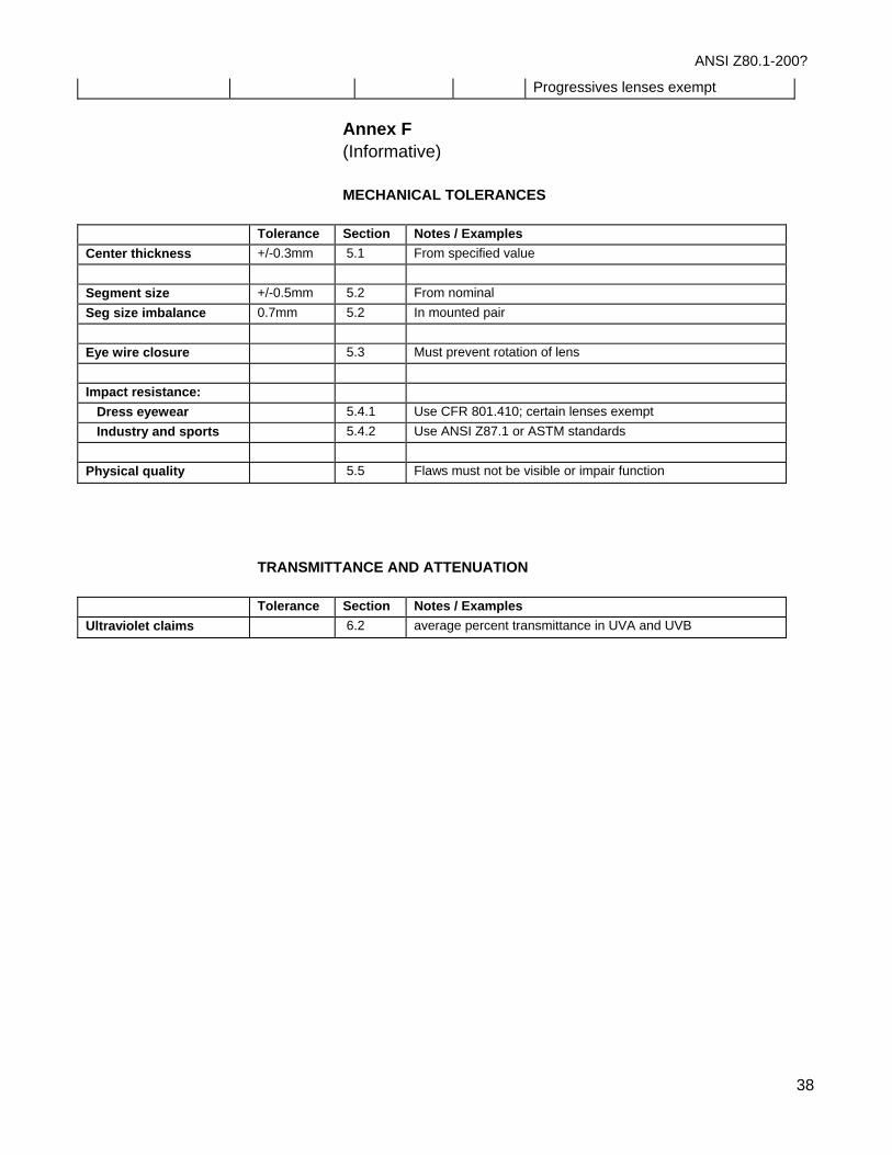
5 Mechanical Requirements Note: A summary of mechanical and transmittance requirements appears in informative Annex F.
5.1 Center Thickness The center thickness of the lens may be specified by the prescriber or may be agreed between prescriber and supplier. Thickness shall not differ more than + 0.3 mm from the specified value. Measurement shall be made normal to the convex surface at the prism reference point.
5.2 Segment Size Segment width, depth, and intermediate depth shall not differ from the nominal value by more than + 0.5 mm when measured using the methods in 7.7.
The difference between the segment dimensions (width, depth, and intermediate depth) in the mounted pair shall not exceed 0.7 mm.
5.3 Eye wire closure The eye wire closure of the lens mounted in the frame shall be sufficient to prevent the lens from rotating.
5.4 Impact resistance
5.4.1 Prescription impact-resistant dress eyewear lenses All lenses must conform to the impact resistance requirements of Title 21, Code of Federal Regulations, 801.410 (CFR 801.410). The impact test of CFR 801.410 is described in 7.9. Laminated, plastic and raised-ledge multifocal lenses may be certified by the manufacturer as conforming to the initial design testing or statistically significant sampling as specified by CFR 801.410.
All monolithic (not laminated) glass lenses shall be treated to be resistant to impact.
5.4.1.1 Special corrective lenses Certain lenses prescribed for specific visual needs are not suitable for the drop-ball technique of testing. Wherever possible, such lenses shall be treated to be resistant to impact or made of impact resistant materials; however, impact testing requirements are waived by the FDA. These lens types include:
- Prism segment multifocals;
- Slab-off prisms;
- Lenticular cataracts;
- Iseikonics;
- Depressed segment one-piece multifocals;
- Biconcaves, myodiscs and minus lenticulars;
- Custom laminates and cemented assemblies.

ANSI Z80.1-200?
17
5.4.2 Prescription Lenses Used for Personal Protective Eyewear in Industry and Eye Protectors for Use by Players of Selected Sports Industrial safety eyewear requirements are found in ANSI Z87.1-1999. Requirements for players of racket sports are found in ASTM F 08.03 -1997.
5.5 Physical Quality and Appearance In a zone of 30 mm diameter centered around the distance reference point and over the whole area of the segment if the segment is equal to or less than 30 mm (for segments over 30 mm diameter zone centered around the near reference point), the lens when inspected using the method described in 7.11 shall not exhibit any surface Imperfections or internal defects including pits, scratches, grayness, bubbles, cracks, striae, or watermarks that are visible and that would impair function of the lens.
Outside this zone, small isolated material or surface defects or both are acceptable.
6 Transmittance & Attenuation Requirements
6.1 Spectrally Attenuating Materials Manufacturers of materials which directly transmit optical radiation shall make spectral transmittance characteristics available to processors, fabricators and to the professions. How the manufacturer obtained the data shall be described.
NOTE — Attenuation in this sense, means loss in transmittance by reflection, scatter, or absorption.
6.2 Ultraviolet (UV) Attenuating Lenses Manufacturers of lenses who claim specific ultraviolet attenuating properties shall state the average percent transmittance between 290 and 315nm (UVΒ) and between 315 and 380nm (UVΑ). The method for determining mean ultraviolet transmittance is shown in 7.13.
ANSI Z80.1-200?
18
7 Test Methods
7.1 Focimeter Use The measurement of distance refractive power and addition power shall be carried out using a focimeter that complies with the requirements of ISO 8598.
For manual focimeters:
Focus the eyepiece of the instrument before attempting to read any power.
The target should be nearly centered on the reticle to ensure a clear target measurement. If necessary, auxiliary prisms can be used to approximately center the target.
In reading the power of a lens, always come back into the focus range from the minus side of focus. Do not focus back and forth by small amounts on both sides of the test focus as this procedure stimulates accommodation and produces erroneous readings.
7.2 Distance Power Single vision lenses and the distance portion of multifocals can be measured using the following procedure:
1. Place the back surface of the lens against the lens positioning tube, or stop, of the focimeter. Ensure that the surface of the lens is in intimate contact with the lens stop;
2. Position the lens with the distance reference point centered in front of the lens stop.
• For non-aspheric single vision and multifocal lenses, the distance reference point corresponds to both the prism reference point and the fitting point.
• For progressive addition and aspheric lenses, the distance reference point should be located using either the manufacturer’s recommendation or an appropriate centration chart.
3. When measuring assembled spectacles, ensure that the bottom of the frame is in firm contact with the focimeter stage for both lenses. Adjust the focimeter stage position so that this can be accomplished while fulfilling the requirements of Step 2 above; and
4. With the lens correctly positioned, measure the power in accordance with the focimeter manufacturer’s instructions.
7.3 Addition Power 1. Place the surface of the lens containing the segment (typically the front surface) against the lens
stop of the focimeter, as described in 6.1.1. This is especially critical in plus-powered lenses.
2. Measure the refractive power through the distance portion;
• For non-aspheric multifocal lenses, maximum accuracy will be obtained when the distance portion is measured at a point as far above the distance reference point as the near reference point is below it, and along a line passing through both the distance reference point and the near reference point. This is illustrated in Figure 6.1:1 below.
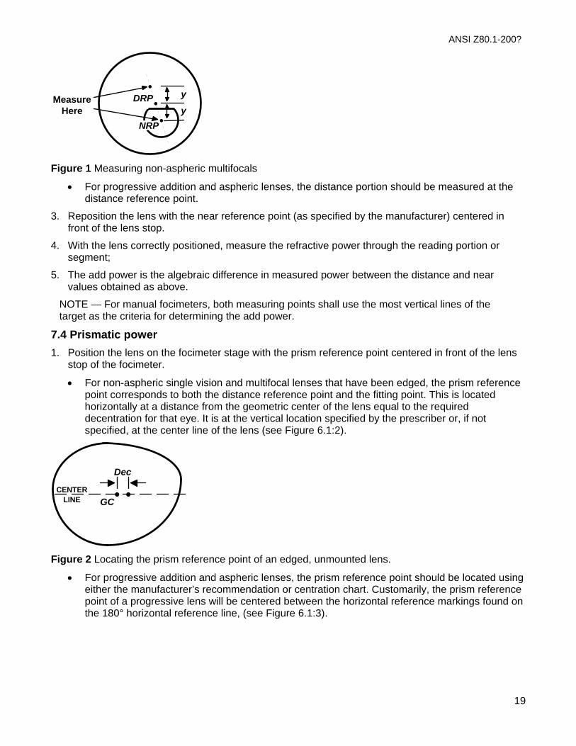
ANSI Z80.1-200?
y
y•
•DRP
NRP
MeasureHere
•
Figure 1 Measuring non-aspheric multifocals
• For progressive addition and aspheric lenses, the distance portion should be measured at the distance reference point.
3. Reposition the lens with the near reference point (as specified by the manufacturer) centered in front of the lens stop.
4. With the lens correctly positioned, measure the refractive power through the reading portion or segment;
5. The add power is the algebraic difference in measured power between the distance and near values obtained as above.
NOTE — For manual focimeters, both measuring points shall use the most vertical lines of the target as the criteria for determining the add power.
7.4 Prismatic power 1. Position the lens on the focimeter stage with the prism reference point centered in front of the lens
stop of the focimeter.
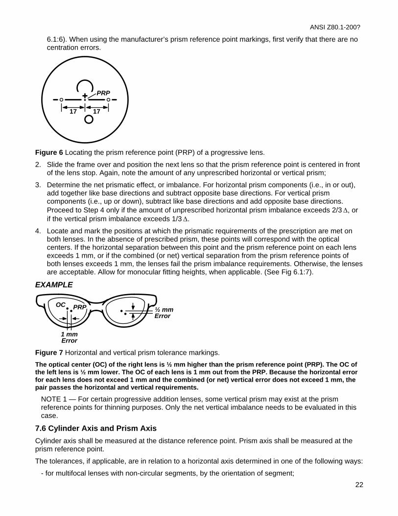
• For non-aspheric single vision and multifocal lenses that have been edged, the prism reference point corresponds to both the distance reference point and the fitting point. This is located horizontally at a distance from the geometric center of the lens equal to the required decentration for that eye. It is at the vertical location specified by the prescriber or, if not specified, at the center line of the lens (see Figure 6.1:2).
•LINE •GC
Dec
CENTER
Figure 2 Locating the prism reference point of an edged, unmounted lens.
• For progressive addition and aspheric lenses, the prism reference point should be located using either the manufacturer’s recommendation or centration chart. Customarily, the prism reference point of a progressive lens will be centered between the horizontal reference markings found on the 180° horizontal reference line, (see Figure 6.1:3).
19

ANSI Z80.1-200?
•
17 17
PRP
Figure 3 Locating the prism reference point (PRP) of a progressive addition lens
• For uncut single vision lenses, the prism reference point should be located at the geometric center of the blank, unless otherwise specified.
• For uncut multifocal lenses, the prism reference point will be located horizontally at a distance from the center of the segment equal to the segment inset. It is located vertically at the DRP Above Seg Line (see Figure 6.1:4).
•
Inset
AboveDRP
Figure 4 Locating the prism reference point of an uncut multifocal
2. Measure the prism at the PRP. Proceed to Step 3 only if the prism error exceeds 1/3 Δ at the prism reference point.
3. Locate and mark the position at which the prismatic requirements of the prescription are met. In the absence of prescribed prism this point corresponds with the optical center. This point must be within 1 mm of the prism reference point as specified in 5.1.5.
7.5 Prism Imbalance of Mounted Pairs
7.5.1 Vertical Imbalance for Single Vision and Multifocal Lenses 1. Select the lens with the strongest refractive power through the vertical meridian; if the lenses have
similar powers, select the lens with the most prescribed vertical prism (if any).
2. Locate and mark the position at which the prismatic requirements of the prescription are met. Ensure that the bottom rims of the spectacle frame are resting evenly upon the stage of the focimeter. In the absence of prescribed prism, this point corresponds with the optical center.
3. Slide the frame over, without moving the focimeter stage, and position the next lens so that any target displacement is in the vertical (90°) meridian (i.e. no horizontal displacement. Mark the lens, and note the amount of vertical prism imbalance. Proceed to Step 4 only if the prismatic imbalance exceeds 1/3 Δ.
4. Reposition the lens in the focimeter, locate and then mark the position at which the prismatic requirements of the prescription are met. If the vertical separation between the first and second
20

ANSI Z80.1-200?
markings exceeds 1 mm, the lenses fail the vertical imbalance requirement. Otherwise, the lenses are acceptable.
NOTE 1 — when differing prism reference points or fitting heights are specified, compensation should be made.
NOTE 2 — in certain cylinder/axis combinations it may not be possible to achieve displacement only in the vertical meridian.
7.5.2 Horizontal Imbalance for Single Vision and Multifocal Lenses 1. If the position on each lens where the prismatic requirements of the prescription are met is not
already marked, do so now.
2. Measure the horizontal distance between these markings.
3. Proceed to Steps 4 and 5 only if this distance is not within 2.5 mm of the specified interpupillary distance.
4. Replace the mounted lens pair in the focimeter, centering the prism reference point of the lens with the strongest refractive power through the horizontal meridian in front of the lens stop. If the measured distance from step 2 (the distance between the positions at which the prismatic requirements of the prescription are met) is wider than the specified interpupillary distance, slide the lens out until 1/3 Δ is induced. Mark the lens at this position. Repeat this for the other lens. If the measured distance is narrower than the specified interpupillary distance, slide the lens in from the lens stop instead.
5. Two sets of focimeter ink markings should now exist on each lens; the inside (nasal) markings on these lenses form the inside pair, and the outside (temporal) markings form the outside pair. If the specified interpupillary distance is narrower than the inside pair, or if the interpupillary distance is wider than the outside pair, the lenses fail the horizontal imbalance requirement. Otherwise, the lenses are acceptable. This is illustrated in Figure 6.1:5.
EXAMPLE Desired PD
• •• •
Actual OCD
Outside PairΔ1/3
Inside
Δ1/3
Figure 5 Horizontal prism tolerance markings. The actual distance between optical centers (OCD) is narrower than the specified interpupillary distance (PD). Outside markings have been placed where 1/3 Δ has been induced. Because the outside markings are wider than the PD, the pair passes the horizontal requirements.
7.5.3 Vertical and Horizontal Imbalance for Progressive Lenses 1. Position the right lens on the focimeter stage with the prism reference point centered in front of the
lens stop of the focimeter. Ensure that the bottom rims of the spectacle frame are resting evenly upon the stage of the focimeter. Note the amount of unprescribed vertical and horizontal prism, if any.
The prism reference point should be located using either the manufacturer’s recommendation or centration chart. Customarily, the prism reference point of a progressive lens will be centered between the horizontal reference markings found on the 180° horizontal reference line (see Fig
21
ANSI Z80.1-200?
6.1:6). When using the manufacturer’s prism reference point markings, first verify that there are no centration errors.
•
17 17
PRP
Figure 6 Locating the prism reference point (PRP) of a progressive lens.
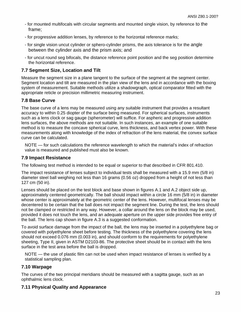
2. Slide the frame over and position the next lens so that the prism reference point is centered in front of the lens stop. Again, note the amount of any unprescribed horizontal or vertical prism;
3. Determine the net prismatic effect, or imbalance. For horizontal prism components (i.e., in or out), add together like base directions and subtract opposite base directions. For vertical prism components (i.e., up or down), subtract like base directions and add opposite base directions. Proceed to Step 4 only if the amount of unprescribed horizontal prism imbalance exceeds 2/3 Δ, or if the vertical prism imbalance exceeds 1/3 Δ.
4. Locate and mark the positions at which the prismatic requirements of the prescription are met on both lenses. In the absence of prescribed prism, these points will correspond with the optical centers. If the horizontal separation between this point and the prism reference point on each lens exceeds 1 mm, or if the combined (or net) vertical separation from the prism reference points of both lenses exceeds 1 mm, the lenses fail the prism imbalance requirements. Otherwise, the lenses are acceptable. Allow for monocular fitting heights, when applicable. (See Fig 6.1:7).
EXAMPLE
• •• •
1 mm
½ mm
Error
Error
OC PRP
Figure 7 Horizontal and vertical prism tolerance markings. The optical center (OC) of the right lens is ½ mm higher than the prism reference point (PRP). The OC of the left lens is ½ mm lower. The OC of each lens is 1 mm out from the PRP. Because the horizontal error for each lens does not exceed 1 mm and the combined (or net) vertical error does not exceed 1 mm, the pair passes the horizontal and vertical requirements.
NOTE 1 — For certain progressive addition lenses, some vertical prism may exist at the prism reference points for thinning purposes. Only the net vertical imbalance needs to be evaluated in this case.
7.6 Cylinder Axis and Prism Axis Cylinder axis shall be measured at the distance reference point. Prism axis shall be measured at the prism reference point.
The tolerances, if applicable, are in relation to a horizontal axis determined in one of the following ways:
- for multifocal lenses with non-circular segments, by the orientation of segment; 22
ANSI Z80.1-200?
23
- for mounted multifocals with circular segments and mounted single vision, by reference to the frame;
- for progressive addition lenses, by reference to the horizontal reference marks;
- for single vision uncut cylinder or sphero-cylinder prisms, the axis tolerance is for the angle between the cylinder axis and the prism axis; and
- for uncut round seg bifocals, the distance reference point position and the seg position determine the horizontal reference.
7.7 Segment Size, Location and Tilt Measure the segment size in a plane tangent to the surface of the segment at the segment center. Segment location and tilt are measured in the plan view of the lens and in accordance with the boxing system of measurement. Suitable methods utilize a shadowgraph, optical comparator fitted with the appropriate reticle or precision millimetric measuring instrument.
7.8 Base Curve The base curve of a lens may be measured using any suitable instrument that provides a resultant accuracy to within 0.25 diopter of the surface being measured. For spherical surfaces, instruments such as a lens clock or sag gauge (spherometer) will suffice. For aspheric and progressive addition lens surfaces, the above methods are not suitable. In such instances, an example of one suitable method is to measure the concave spherical curve, lens thickness, and back vertex power. With these measurements along with knowledge of the index of refraction of the lens material, the convex surface curve can be calculated.
NOTE — for such calculations the reference wavelength to which the material’s index of refraction value is measured and published must also be known.
7.9 Impact Resistance The following test method is intended to be equal or superior to that described in CFR 801.410.
The impact resistance of lenses subject to individual tests shall be measured with a 15.9 mm (5/8 in) diameter steel ball weighing not less than 16 grams (0.56 oz) dropped from a height of not less than 127 cm (50 in).
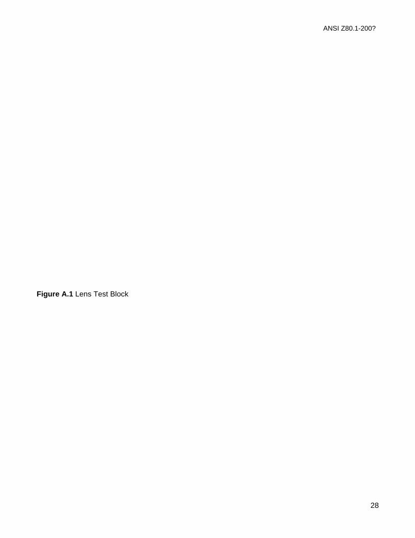
Lenses should be placed on the test block and base shown in figures A.1 and A.2 object side up, approximately centered geometrically. The ball should impact within a circle 16 mm (5/8 in) in diameter whose center is approximately at the geometric center of the lens. However, multifocal lenses may be decentered to be certain that the ball does not impact the segment line. During the test, the lens should not be clamped or restricted in any way. However, a collar around the lens on the block may be used, provided it does not touch the lens, and an adequate aperture on the upper side provides free entry of the ball. The lens cap shown in figure A.3 is a suggested conformation.
To avoid surface damage from the impact of the ball, the lens may be inserted in a polyethylene bag or covered with polyethylene sheet before testing. The thickness of the polyethylene covering the lens should not exceed 0.076 mm (0.003 in), and should conform to the requirements for polyethylene sheeting, Type II, given in ASTM D2103-86. The protective sheet should be in contact with the lens surface in the test area before the ball is dropped.
NOTE — the use of plastic film can not be used when impact resistance of lenses is verified by a statistical sampling plan.
7.10 Warpage The curves of the two principal meridians should be measured with a sagitta gauge, such as an ophthalmic lens clock.
7.11 Physical Quality and Appearance

ANSI Z80.1-200?
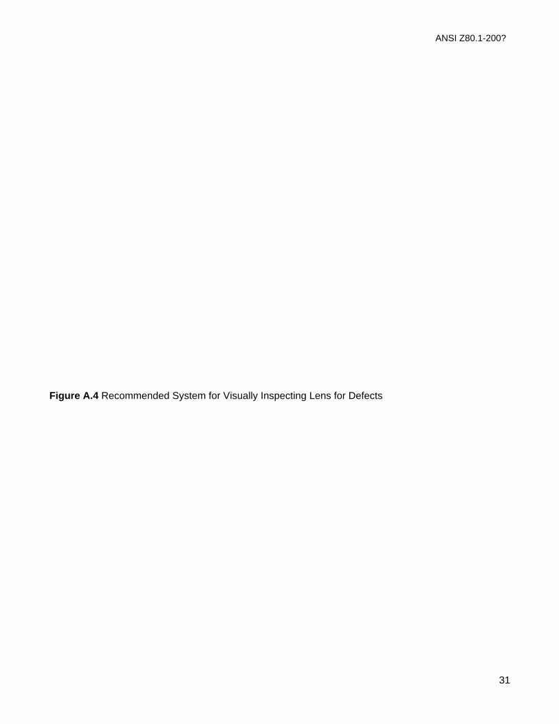
The lens inspection is carried out at a light/dark boundary and without the aid of magnifying optics. Inspect the lens within a room with ambient lighting of about 200 lux. Use as an inspection lamp either a fluorescent tube with a minimum of 15 W or an open shaded 40 W incandescent clear lamp. Position the lens about 300 mm from the light source and view against a dark background.
NOTE 1 — This observation is subjective and requires some experience.
NOTE 2 — The diaphragm is adjusted to shield the eye from the light source and to allow the lens to be illuminated by the light (see figure A.4).
7.12 Localized Error View a high-contrast grid pattern of dark and light lines through the lens, scanning the lens area by area. The lens should be held approximately 305 mm (12 inches) from the eye for weak plus or minus lenses. For strong plus lenses, the eye should be placed near the focus. The target should be at least 305 mm (12 inches) from the lens.
Virtually any straight-edged object is suitable for viewing waves through minus lenses. A grid pattern as viewed through the lens, should appear smoothly curved and gradually distorted from the center of the field outward.
However, localized ripples or distortions that are visible to the unaided eye are an indication of a possible significant aberration. The area should be marked for evaluation in a focimeter. Localized ripples or distortions that are invisible to the unaided eye may be disregarded.
7.13 Calculation of Mean Ultraviolet Transmittance The mean transmittance, τ (λ1, λ2), of a lens over a spectral range λ1 to λ2 is expressed mathematically as follows:
( ) ( )τ λ λλ λ
τ λ λλ
λ
1 22 1
11
2, =− ∫ d
where:
τ(λ) is the spectral transmittance of the lens.
Mean transmittance values are applicable only to the following ultraviolet spectral zones:
UVB (Erythemal zone): λ1 = 290 nm, λ2 = 315 nm;
UVA (Near Ultraviolet Zone): λ1 = 315 nm, λ2 = 380 nm.
The integral may be evaluated by using continuous functions or by dividing the specified spectral range into a finite number of intervals, no greater than 5 nm wide, and replacing the integral by a finite summation as follows:
( )( )
τ λ λτ λ λ
λ
λ
λ
λ
λ1 21
2
1
2, =
∑
∑
Δ
Δ
where:
Δλ < 5 nm
NOTE — As examples, the formulas listed below give the mean ultraviolet transmittance according to the above finite summation for intervals of 5 nm width.
24

ANSI Z80.1-200?
25
UVB: ( )τ τUVB = +=∑5
25292 5 5
0. i
i
4
UVA: ( )τ τUVA=65 0i
= +∑53175 5. i
12
However, the proponents of alternate test procedures shall establish functional equivalence to these reference tests. Furthermore, in cases where state or federal jurisdictions apply, variations in test or inspection procedures shall be acceptable only when functional evidence has been demonstrated.
7.14 Alternate test methods It is not the intention of this standard to restrict measurement techniques, performance tests, and inspection procedures to those described herein.

ANSI Z80.1-200?
26
8 Identification
The identification of the completed spectacle or component shall be specified on the package of the completed spectacle or in an accompanying document.
8.1 Information to be provided by a supplier of spectacle components or completed spectacles
- Corrective power (using the helium d-line as the reference wavelength); - Color (if not white) and coating; - Material and material index (using the helium d-line as the reference wavelength), or
manufacturer’s or supplier’s trade name or equivalent; This standard permits the use of other reference wavelengths but requires that a statement always be included giving the index of refraction, Abbe value and lens power using the helium d-line reference wavelength;
- Impact test results (in accordance with requirements of Title 21, CFR 801.410); - Distance P.D.; and - Lens style designation or trade name.
For multifocals:
- Addition power (using the helium d-line as the reference wavelength); - Segment dimension (if applicable); - Segment height; and - Segment prism;
For the frame:
- Manufacturer’s identification; - Manufacturer’s model identification; - Color; - Horizontal boxed lens size; - Distance between lenses; - Overall temple length; - Material identification; and - Country of origin (in accordance with regulation).
8.2 Information to be supplied by the laboratory on request - Center or edge thickness; - Nominal or actual base curve; - Optical properties (dispersion, transmittance); and - Thickness reduction prism.
8.3 Identification of the standard
If the manufacturer or supplier claims compliance to this standard, reference shall be made to the ANSI Z80.1-1999 either on the package or in available literature.
ANSI Z80.1-200?
27
Annex A (Informative)
Technical Addendum to Impact Testing A.1 Impact Resistance Annex A is included as a recommendation and guideline to complement this standard in the processing of currently available impact-resistant lenses.
Thickness guideline: Air-tempered glass lenses should be no less than 2.0 mm thick at the prism reference point and have no less than a 1.0 mm edge thickness at the thinnest point of the edged lens.
A.1.1 Strengthening Techniques
A.1.1.1 Air Tempering (Thermal Toughening) A.1.1.1.1 Process Description Air tempering (thermal toughening) is a process whereby a glass lens is heated in a furnace to a temperature near but below the softening point of the glass for a period of time dependent upon its size and weight or average thickness. The lens is then quickly removed from the furnace and subjected to rapid chilling (quenching) by use of forced-air blasts on it surfaces. The controlled heating-cooling cycle places the surfaces and edges of the lens in a state of compression and the inner core of the lens in a state of tension.
A.1.1.1.2 Process Monitoring Air-tempering (thermal toughening) equipment must be maintained by periodic inspections. Weight scales or calipers, timers, air filters, and furnace temperatures should be monitored at regular intervals and maintained in accordance with the manufacturer’s instruction manual.
A.1.1.2 Chemical Tempering (Ion-Exchange Toughening) A.1.1.2.1 Process Description Chemical tempering, like air tempering, strengthens glass lenses by placing their surfaces into a state of compression, while placing the interior of the lens into a state of tension. The process for currently available white crown and most tints involves exchanging sodium ions in the surface of the lens for potassium ions from a molten salt bath. Some photochromic materials require a sodium-for-lithium ion exchange system, as adequate results cannot be obtained using the white crown system. The temperature and purity of the molten salts and time of immersion will determine the quality of the strengthening (depth of penetration of the exchange layer and surface compression value.)
A.1.1.2.2 Process Monitoring Chemical tempering equipment must be inspected at periodic intervals and maintained and operated in accordance with the manufacturer’s instruction manual. Salt should be added when needed to maintain the proper bath level. Lenses must be completely submerged during processing. Since the activity of the ion exchange salts decreases or more lenses are processed, the salt should be replaced or replenished periodically, according to manufacturer’s recommendations.
ANSI Z80.1-200?
28
Figure A.1 Lens Test Block

ANSI Z80.1-200?
29
Figure A.2 Base Plate

ANSI Z80.1-200?
30
Figure A.3 Lens Cap
ANSI Z80.1-200?
31
Figure A.4 Recommended System for Visually Inspecting Lens for Defects

ANSI Z80.1-200?
32
Annex B (Informative)
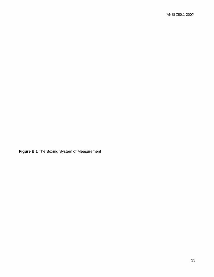
The Boxing System of Measurement A unit of frame and lens measurement, called the boxing system, was instituted in 1962. Since that time, most products manufactured in the United States conform to this system. The salient features of the system, as it applies to this standard, are shown in figure B.1. Basically, all measurements are made from frame or lens centers and the lens bevel apexes and are expressed in millimeters.
A – The horizontal box dimension or the horizontal distance between two vertical tangents tot he lateral extremities of the lens shape;
B – The vertical box dimension or the vertical distance between two horizontal tangents to the vertical extremities of the lens shape;
DBL – Distance between lenses (measured between two vertical tangents to the nasal extremities of the lens bevels);
DBC – Distance between centers (the distance between the two geometric centers of the frame eyewires) see GC;
GC – The geometric center of the box, eyewire, or lens shape;
NPD – Near interpupillary distance or the horizontal distance between segment geometric centers;
DPD – Distance interpupillary distance or the horizontal distance between major reference points;
DRP – Distance reference point (see 3.20.1);
θ – Angle of the cylinder axis, measured in a counterclockwise direction from 0 degrees. Zero degrees, by convention, always is the right extremity of the box when viewing the patient (i.e., the patient’s left);
OD – Right eye;
OS – Left eye.
ANSI Z80.1-200?
33
Figure B.1 The Boxing System of Measurement
ANSI Z80.1-200?
34
Annex C (Informative)
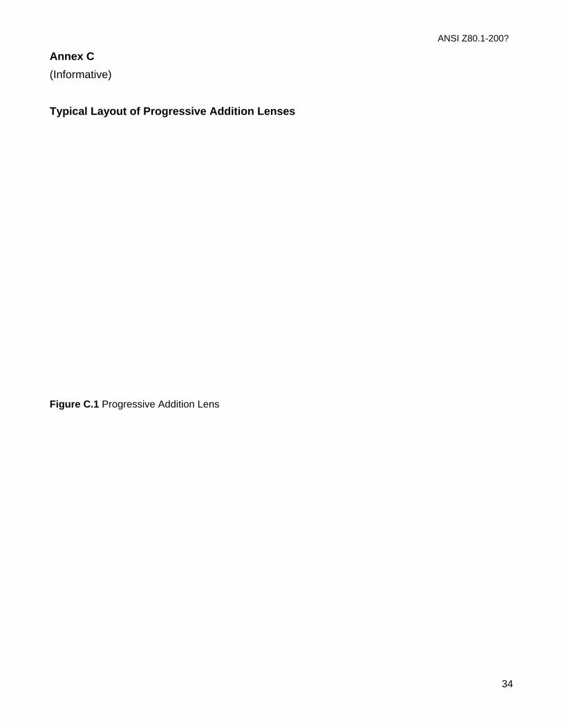
Typical Layout of Progressive Addition Lenses
Figure C.1 Progressive Addition Lens
ANSI Z80.1-200?
35
Annex D (Informative)
Reference Method for Evaluating Progressive Addition Lens Characteristics D.1 The purpose of this annex is to provide a reference method for specifying certain optical properties of progressive addition lenses. It is not the intent to standardize what the optics should be or how those optics affect the use or acceptance of these lenses.
Other methods that provide measurements that are equivalent tot his reference method are also acceptable.
D.2 The characterization can be composed of several parameters, but should at least include spherical equivalent and astigmatism as follows:
- Spherical equivalent is the mean of the two principal meridian powers (D1 and D2) at any point on the lens;
- Astigmatism is the difference between the principal meridian powers; and
- It is possible to measure and plot other parameters such as prism. Future developments may indicate which measures are the most useful.
The reference method for measuring these characteristics should be that using a focimeter which meets the requirements of ISO 8598 and is especially adapted for these measurements (see figure D.1). The manufacturer should specify the aperture used in the measuring instrument.
The principal ray path (or the instrument axis if applicable) should intersect both the measuring point and the optical center of rotation of the eye.
The δ should be at least + 40° from the fitting point in all directions except for the downward direction which should be > 45°.
From these characterizations a measurement with infinity distance has been chosen.
The recommended representations of the optical measurements across the lens are contour plot diagrams.
The reference test lenses for progressive addition lenses of the base curve specified by the manufacturers surfacing chart should have the following characteristics:
- distance power: plano; - addition power: + 2.00 D.
For other base curves and addition powers the manufacturer will indicate the base curve, distance power and addition power of the lenses used.
ANSI Z80.1-200?
36
Figure D.1 Diagram of Progressive Lens Positioning for Evaluating Progressive Lens Characteristics
ANSI Z80.1-200?
37
Annex E (Informative) OPTICAL TOLERANCES Sphere powers Tolerance Section Notes / Examples Sphere power 0.00D to 6.50D +/-0.13D 4.2.1 over 6.50D +/-2% Tolerance is 2% of specified power Cylinder power 0.00 to 2.00D +/-0.13D 4.2.1 2.25 to 4.50D +/-0.15D over 4.50D +/-4% Tolerance is 4% of specified power Cylinder axis 0.00 to 0.37D +/-7deg 4.3.1 >0.37 but
<=0.75D +/-5deg Note: > means greater than;
>0.75 but<=1.50D +/-3deg <= means less than or equal to over 1.50D +/-2deg Prism: Power either 0.33d 4.2.4 Measured at PRP; d = prism diopter PRP location or 1.0mm Applies only if prism power error >0.33d Prism Imbalance: Vertical, all lenses either 0.33d 4.3.5 If greater than 0.33 use mm tolerance or 1.0mm Tolerance applies to monocular locations Horizontal: Progressive lens either 0.67d 4.3.5 If greater than 0.67 use mm tolerance or 1.0mm Tolerance applies to monocular locations All other lenses either 2.5mm 4.3.5 From specified PD or 0.67d At PD if greater than 2.5mm error Add power <=4.00D +/-0.12 4.2.3 >4.00D +/-0.18 Segment: Tilt +/-2 deg 4.3.2 Vertical location +/-1.0mm 4.3.3 Vertical imbalance 1mm 4.3.3 Mounted lens pair Horizontal location 4.3.4 Symmetrical unless specified otherwise Horiz imbalance +/-2.5mm 4.3.4 Mounted pair; progressive lenses exempt Base curve +/-0.75D 4.2.5 Only when specified Lens warp +/-1.00D 4.2.6 Cylinder induced in front surface Localized errors 4.2.7 Permitted if not found by focimeter >30mm from MRP exempt <6mm from edge exempt
ANSI Z80.1-200?
38
Progressives lenses exempt Annex F (Informative) MECHANICAL TOLERANCES Tolerance Section Notes / Examples Center thickness +/-0.3mm 5.1 From specified value Segment size +/-0.5mm 5.2 From nominal Seg size imbalance 0.7mm 5.2 In mounted pair Eye wire closure 5.3 Must prevent rotation of lens Impact resistance: Dress eyewear 5.4.1 Use CFR 801.410; certain lenses exempt Industry and sports 5.4.2 Use ANSI Z87.1 or ASTM standards Physical quality 5.5 Flaws must not be visible or impair function
TRANSMITTANCE AND ATTENUATION Tolerance Section Notes / Examples Ultraviolet claims 6.2 average percent transmittance in UVA and UVB
ANSI Z80.1-200?
39
Annex G (Informative)
Bibliography ISO 10322-1-1991, Ophthalmic optics – Semi- finished lens blanks part 1: Specifications for single vision and multifocal lens blanks4
1 Available from the American National Standards Institute, 11 West 42nd Street, New York, NY 10036 (Website WWW.ANSI.ORG) 2 Available from the American Society of Testing Materials, 100 Barr Harbor Drive, West Conshohocken, PA 19428 (Website WWW.ASTM.ORG) 3 Available from the Government Printing Office, P.O. Box 371954, Pittsburgh, PA 15250-7954 4 Available from the Optical Laboratories Association, P.O. Box 2000, Merrifield, VA 22116-2000
ISO 10322-2-1991, Ophthalmic optics – Semi- finished lens blanks part 2: Specifications for progressive power lens blanks4
ASTM D2240-91, Test methods for rubber properties – Durometer hardness2
ASTM D412-92, Test methods for rubber properties – Tension2
ANSI/AFBMA 10-1993, Specifications for Metal Balls1
ISO 7944-1984, Optics and Optical Instruments — Reference Wavelengths4
Impact Resistant Lenses: Questions and Answers (Revised 1987). U.S. Department of Health and Human Services, Public Health Service, Food and Drug Administration, Center for Devices and Radiological Health3
ISO 8429-196, Optics and Optical Instruments — Ophthalmology — Graduated Dial Scale4
ISO 8980-1-1992, Ophthalmic Optics- Finished Single Vision Corrective Lenses Part 1: General Requirements1
ISO 9456-1991, Optics and Optical Instruments- Ophthalmic Optics- Marking of Spectacle Frames1