annual report: september 2008- august2009 · · 2011-05-14results have been obtained for...
TRANSCRIPT

Aerodynamic Investigation of Smart Flying Wing MAVAOARD Grant No. FA2386-08-1-4088
Goal:
Numerical simulations to assess the feasibility of using embedded piezo sensors-actuators within thin wings to make them adaptive and therefore more aerodynamically efficient.
Applications:
This concept if found attractive through numerical simulations and subsequent experimental validation, could lead to designing practical smart MAV wings. The application would not be restricted to flying wing MAV configurations alone.
Uniqueness: The potential of embedded piezoelectric sensors and actuators in shape control of wings is not explored extensively. Their role in tailoring micro aerodynamic surfaces could be very useful in controlling the aerodynamics of
MAV wings.
Principal Investigator (PI): Dr. Arnab Roy I.I.T. Kharagpur, India
Initial Whitepaper Outline
Annual Report: September 2008-
August2009

Report Documentation Page Form ApprovedOMB No. 0704-0188
Public reporting burden for the collection of information is estimated to average 1 hour per response, including the time for reviewing instructions, searching existing data sources, gathering andmaintaining the data needed, and completing and reviewing the collection of information. Send comments regarding this burden estimate or any other aspect of this collection of information,including suggestions for reducing this burden, to Washington Headquarters Services, Directorate for Information Operations and Reports, 1215 Jefferson Davis Highway, Suite 1204, ArlingtonVA 22202-4302. Respondents should be aware that notwithstanding any other provision of law, no person shall be subject to a penalty for failing to comply with a collection of information if itdoes not display a currently valid OMB control number.
1. REPORT DATE 19 NOV 2009
2. REPORT TYPE FInal
3. DATES COVERED 01-10-2008 to 01-09-2009
4. TITLE AND SUBTITLE Aerodynamic Investigation of Smart Flying Wing MAV
5a. CONTRACT NUMBER FA23860814088
5b. GRANT NUMBER
5c. PROGRAM ELEMENT NUMBER
6. AUTHOR(S) Arnab Roy
5d. PROJECT NUMBER
5e. TASK NUMBER
5f. WORK UNIT NUMBER
7. PERFORMING ORGANIZATION NAME(S) AND ADDRESS(ES) Indian Institute of Technology Kharagpur,Indian Institute of TechnologyKharagpur,Kharagpur, West Bengal 721302,Kharagpur, West Bengal 721302,IN,721302
8. PERFORMING ORGANIZATIONREPORT NUMBER N/A
9. SPONSORING/MONITORING AGENCY NAME(S) AND ADDRESS(ES) AOARD, UNIT 45002, APO, AP, 96337-5002
10. SPONSOR/MONITOR’S ACRONYM(S) AOARD
11. SPONSOR/MONITOR’S REPORT NUMBER(S) AOARD-084088
12. DISTRIBUTION/AVAILABILITY STATEMENT Approved for public release; distribution unlimited
13. SUPPLEMENTARY NOTES This project was renewed; ref AOARD #094109.
14. ABSTRACT Numerical simulations is performed to assess the feasibility of using embedded piezo sensors-actualroswithin thin wings to make them adaptive and therefore more aerodynamically efficient. If the method isfound attractive and validated, could lead to design of practical smart MAV wings, but it also has moregeneral application.
15. SUBJECT TERMS Micro Air Vehicles (MAVs), Aerodynamic Design and Analysis
16. SECURITY CLASSIFICATION OF: 17. LIMITATION OF ABSTRACT Same as
Report (SAR)
18. NUMBEROF PAGES
21
19a. NAME OFRESPONSIBLE PERSON
a. REPORT unclassified
b. ABSTRACT unclassified
c. THIS PAGE unclassified
Standard Form 298 (Rev. 8-98) Prescribed by ANSI Std Z39-18

Approach: An existing 2D structured Incompressible laminar Navier Stokes (NS) solver (details given in 5th slide) was initially extended to 2D unstructured solver (triangular cell based). This solver would be used for studying 2D flow past airfoils. This solver was further extended to a 3D unstructured version. This 3D solver would be used to solve flow past MAV wing. GAMBIT®
would be used for generating the initial mesh. The Structural Analysis Solver would model the MAV wing as a thin shell containing embedded piezo sensors and actuators. It is integrated with the flow solver to compute the fluid structure interaction problem which occurs when considering an elastic wing.
Status and progress:
We have completed extending our existing 2D structured Incompressible laminar Navier Stokes (NS) solver to 2D unstructured solver. Results have been obtained for incompressible flow past single and multiple circular cylinder arrangements and several reflexed and non-reflexed airfoil geometries and the
solver has been validated using results from literature. We are currently working on our 3D unstructured NS solver. It is being used to solve laminar flow past a sphere and an aspect ratio=2.0 rectangular thin reflexed wing. An effort would be made to incorporate a suitable turbulence model in the flow solver depending on time availability.Dr. Anup Ghosh, CO-PI of the project and his scholar is working on the structural solver which would be coupled with the flow solver.

Numerical Simulationresults for incompressible flow past cylinders and various
reflexed and non-reflexed airfoils
using 2D unstructured solver

20 40 60 80 100
1E-5
1E-4
1E-3
0.01
0.1
1
Pres
sure
Poi
sson
Equ
atio
n RM
S Re
sidua
l
Time Steps
Convergence pattern of the 2D unstructured grid solver for flow past a single circular cylinder at Reynolds number (Re)=100 (using approximately 30000 triangular cells)

Streamlines and vorticity contours for two and three circular cylinders
placed side by side for Reynolds number 200

1. Reflexed airfoils ( airfoil having negative camber over some portion of the chord near the trailing edge)
(i) Eppler series(ii) S series
2. Low pitching moment airfoils
(i) MH series
“A Finite Volume Method for Incompressible Flows Using a Consistent Flux Reconstruction Scheme*”, A. Roy and G. Bandyopadhyay, International Journal for Numerical Methods in Fluids, Vol. 52, pp. 297-319, 2006…..a two dimensional curvilinear collocated structured grid based laminar incompressible finite volume solver for solving flow past arbitrary geometries
*The above numerical scheme has been developed by the PI and has been referred to as ‘CFR’
scheme henceforth
The Original Numerical Scheme
The airfoils that have been identified at this stage for numerical investigation

Comparison of time averaged surface pressure distribution on NACA 0002 airfoil at Re=103, α=00.
*Kunz, J. and Kroo, I. Analysis and Design of Airfoils for Use at Ultra-Low Reynolds numbers, Chapter 3, Fixed and Flapping Wing Aerodynamics for Micro Air Vehicle Applications, Ed. T. J. Mueller, Volume 195, Progress in Astronautics and Aeronautics, AIAA, 2001.
0.0 0.2 0.4 0.6 0.8 1.0
1.0
0.8
0.6
0.4
0.2
0.0
-0.2
Result of Kunz and Kroo [7] Present result
Cp
x/c
(2001)*

Results of simulations performed at Re=104
for E 330 (reflex angle δ=5.3º) and
E 334 (reflex angle δ=2.6º) airfoils using unstructured 2D CFR solver
0 2 4 6 8 10 12
0.0
0.2
0.4
0.6
0.8
1.0
E 330 E 334
Cl
0 2 4 6 8 10 12
-0.050
-0.025
0.000
0.025
0.050
E 330 E 334
Cm
The effect of increasing reflex is captured in principle by the 2D unstructured CFR solver, as is evident from the Cm
-
α
(pitching moment about c/4) plot. By increasing the reflex angle suitably, desired value of pitching moment coefficient for the tailless configuration can be obtained. However, this can be done only at the expense of reduced lift as seen from the Cl
-
α
plot.
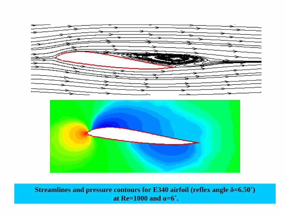
Streamlines and pressure contours for E340 airfoil (reflex angle
δ=6.50˚)at Re=1000 and α=6˚.
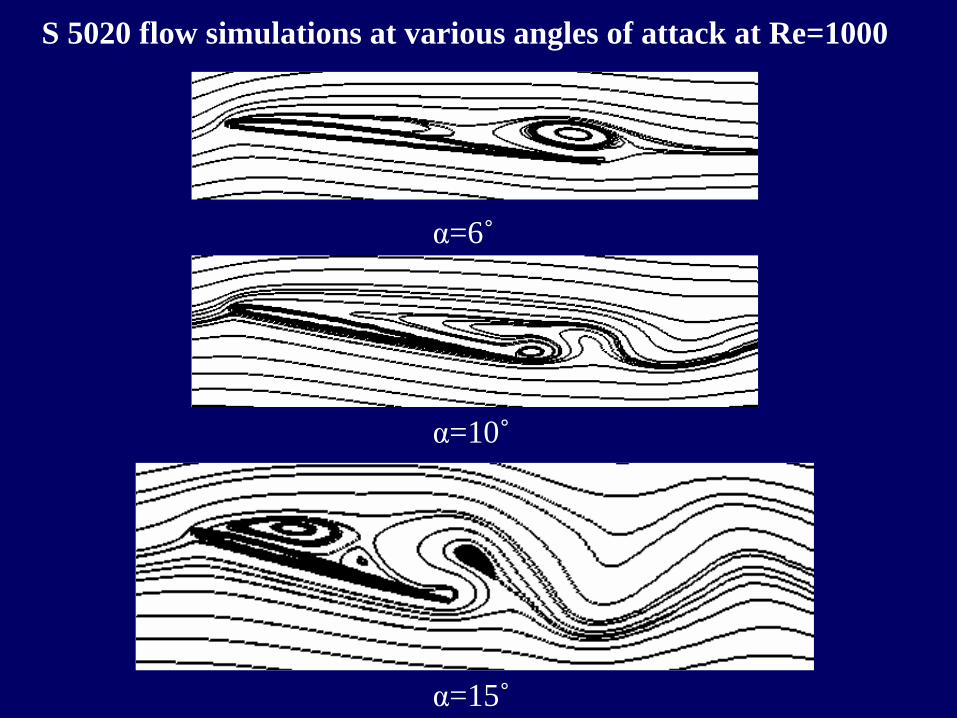
S 5020 flow simulations at various angles of attack at Re=1000
α=6˚
α=10˚
α=15˚
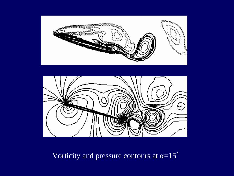
Vorticity and pressure contours at α=15˚

Simulations carried out using Fluent®*
on large number of reflexed airfoils revealing the impact of reflex on pitching moment coefficient and maximum lift coefficient. The simulations were performed for Eppler E335 (δ=6˚
) –339 (δ=3.4˚
) airfoils. The turbulent simulations were performed using k-ω
SST model. All simulations were carried out at Re= 7.2 ×
104.The map indicates the need for an optimization study based on the desired goal. * Commercial CFD software is used for the high Reynolds number simulations as turbulence model is not yet incorporated in the CFR unstructured solver

SOME OBSERVATIONS BASED ON THE NUMERICAL SIMULATIONS
It was observed that increasing the reflex near the trailing edge increases the pitching moment.
However, this increase in pitching moment is accompanied by a decrease in maximum lift coefficient and a decrease in lift at a given angle of attack as observed in the case of both laminar and turbulent flow.
Exactly opposite behavior is noticed if positive camber near the leading edge is increased keeping the reflex angle constant.
The maximum lift to drag ratio seems to improve with increase in Reynolds number.

FUTURE SCOPE OF WORK… Enhancing the capabilities of the present flow solver
to simulate the typical mixed laminar, transitional and fully turbulent flow occurring over a MAV wing. This would ensure accurate capturing of laminar separation bubble which dominates the low Reynolds number aerodynamics.
Wind tunnel tests to reveal (a) the fidelity of numerical simulations and (b) potential of the embedded piezo sensor actuators in tailoring wing geometry and their role as micro flow control device.
Optimization of the MAV wing geometry. This would include several airfoils suitable for the purpose and various low aspect ratio planforms. The optimization goal could be to identify a configuration with best L/D ratio to ensure satisfactory aerodynamic efficiency. Another optimization study would be to identify the optimum location of smart piezo
patches in the wing to maximize its tailorability.
Visit Abroad
PI of the present project visited Institute of Aerospace Thermodynamics (ITLR), University of Stuttgart, Germany under an invitation from Prof. Bernhard Weigand, Director of the Laboratory during May-July, 2009. Travel expenses were met from the AOARD project fund. Other expenses were borne by ITLR.
During this visit some preliminary numerical studies were conducted to explore the aspect of drag reduction in flows occuring
over microtextured
surfaces. Initial results reveal that there could be some drag reduction when an optimum microtexture
pattern is used. This concept could find application in MAV wings for the purpose of drag reduction.
PI of the project also met Prof. Herbert Olivier and Prof. Igor
Klioutchnikov,
SWL, RWTH, Aachen, Germany. Prof. Klioutchnikov
has taken interest in carrying out flow simulations on a few reflexed airfoils of our interest using his WENO based Navier Stokes code. It would be interesting to compare our results with his as and when they are available.

Papers communicated to peer reviewed journals
1.
“Numerical Investigation of Incompressible Low and Moderate Reynolds Number Flow past some Reflexed Eppler Airfoils”, A. Halder, S. Ghosh, A. B. Harichandan* and A. Roy, communicated to Aerospace Science and Technology. (authors have received the initial review report and are presently modifying the paper in response to the reviewers’
comments)
2.
“Numerical Investigation of Low Reynolds Number Flow Past Two andThree Circular Cylinders Using Unstructured Grid CFR Scheme”, A.B. Harichandan and A. Roy, communicated to International Journal of Heat and Fluid Flow.
3.
“Numerical Predictions of Unsteady Incompressible Flows Past Array of Circular Cylinders in Staggered Arrangements”, A.B. Harichandan and A. Roy,
communicated to International Journal for Numerical Methods in Fluids.
Accomplishments
* PI’s Ph.D. student who is also working as a research fellow under the present AOARD project
Conference Publications/ acceptance for publication
1.
“Numerical Investigation of Low Reynolds Number Flow Past Airfoils for Flying Wing MAV”,
A. Roy, Proceedings of INDUS-MAV 2008 Workshop held at NAL and ADE, Bangalore, 13-14th Nov., 2008.
2.
“Computation of Incompressible Flow Past Array of Circular Cylinders Using an Unstructured Grid Finite Volume Approach”, A.B. Harichandan and A. Roy, accepted for publication in in the forthcoming ISHMT
ASME 2010 conference to be held at I.I.T. Mumbai in Jan 2010.

Research Students
Ph.D. scholars
1.
Mr. Atal Bihari Harichandan (working in the AOARD Project since November 2008): working in the area of Aerodynamics
2.
Mr. Sharavankumar
Basavaraj
Kerur
(working in the AOARD Project since June 2009): working in the area of aircraft structures
M.Tech
student
1.
Mr. Kamanasish
Biswas
(worked in the AOARD Project from November 2008-
May 2009): worked in the area of aircraft
structures
* All the above students receive/ received regular scholarship from the Institute and top-up fellowship from the AOARD project