annex ii - amc 20-28 - easa.europa.eu ii - amc... · amc 20-28 page 3 of 23 1. purpose this amc...
TRANSCRIPT
AMC 20-28
Page 1 of 23
AMC 20-28 Effective: 24/09/2012
Annex II to ED Decision 2012/014/R of 17/09/2012
AMC 20-28 Airworthiness Approval and Operational Criteria related to Area
Navigation for Global Navigation Satellite System approach
operation to Localiser Performance with Vertical guidance
minima using Satellite Based Augmentation System
This AMC provides an acceptable means that can be used to obtain airworthiness
approval for an Area Navigation (RNAV) approach system based on Global Navigation
Satellite System (GNSS) augmented by a Satellite Based Augmentation System (SBAS)
in order to conduct approach operations to Localiser Performance with Vertical guidance
(LPV) minima. This AMC also defines the operational criteria necessary to conduct safely
such approach operations in designated European airspace.
TABLE OF CONTENTS
1. PURPOSE .................................................................................................... 3
2. BACKGROUND ............................................................................................. 3
3. SCOPE ......................................................................................................... 3
4. REFERENCE DOCUMENTS ............................................................................ 4
4.1 RELATED REQUIREMENTS ................................................................................... 4 4.2 RELATED MATERIAL ......................................................................................... 4
4.2.1. ICAO ................................................................................................ 4 4.2.2. EASA ................................................................................................ 4 4.2.3. FAA .................................................................................................. 5 4.2.4. EUROCAE / RTCA and ARINC ............................................................... 5
5. ASSUMPTIONS ............................................................................................ 5
5.1 NAVIGATION AID INFRASTRUCTURE ....................................................................... 5 5.2 OBSTACLE CLEARANCE ...................................................................................... 6 5.3 PUBLICATION ................................................................................................. 6 5.4 COMMUNICATION AND ATS SURVEILLANCE .............................................................. 6
6. AIRWORTHINESS CRITERIA ....................................................................... 7
6.1 GENERAL ...................................................................................................... 7 6.2 EQUIPMENT QUALIFICATION ................................................................................ 7
6.2.1 GNSS SBAS Stand-alone Navigation system ............................................. 7 6.2.2 Integrated Navigation system incorporating a GNSS SBAS sensor............... 7 6.2.3 Approach system incorporating class Delta GNSS SBAS equipment ............. 7
6.3 ACCURACY .................................................................................................... 7 6.3.1. Navigational System Error (NSE) ......................................................... 7 6.3.2. Flight Technical Error (FTE) ................................................................. 7 6.3.3. Path Definition Error (PDE) .................................................................. 8
6.4 INTEGRITY .................................................................................................... 8 6.5 CONTINUITY OF FUNCTION ................................................................................. 8
7. FUNCTIONAL CRITERIA .............................................................................. 8
7.1 REQUIRED FUNCTIONS ...................................................................................... 9
8. AIRWORTHINESS COMPLIANCE ................................................................ 10
8.1 GENERAL .................................................................................................... 10
AMC 20-28
Page 2 of 23
8.2 NEW OR MODIFIED INSTALLATIONS ..................................................................... 10 8.3 EXISTING INSTALLATIONS ................................................................................ 10 8.4 SPECIFIC INSTALLATION CRITERIA ...................................................................... 11 8.5 PERFORMANCE EVALUATION FOR LPV APPROACH OPERATION ........................................ 12 8.6 INTERMIXING OF EQUIPMENT ............................................................................. 12
9. AIRCRAFT FLIGHT MANUAL/PILOT OPERATING HANDBOOK .................... 12
10. OPERATIONAL CRITERIA .......................................................................... 13
10.1.FLIGHT OPERATIONS DOCUMENTATION ................................................................. 13 10.2.FLIGHT CREW TRAINING .................................................................................. 13 10.3.AERODROME COMPETENCE AND OPERATOR VERIFICATION ........................................... 13 10.4.NAVIGATION DATABASE MANAGEMENT ................................................................. 14
10.4.1. Operator involved in the operation of aircraft for commercial air
transportation ............................................................................................... 14 10.4.2. Operator not involved in the operation of aircraft for commercial air
transportation ............................................................................................... 14 10.4.3. Reportable Events ............................................................................ 14
11. AVAILABILITY OF DOCUMENTS ................................................................. 15
APPENDIX 1: GLOSSARY ................................................................................ 16
APPENDIX 2: OPERATIONAL CHARACTERISTICS OF THE PROCEDURE AND ITS
OPERATIONAL USE ........................................................................................... 18
APPENDIX 3: LPV APPROACH OPERATIONAL PROCEDURES ........................... 19
APPENDIX 4: FLIGHT CREW TRAINING SYLLABUS ......................................... 22
AMC 20-28
Page 3 of 23
1. PURPOSE
This AMC provides an acceptable means that can be used to obtain airworthiness
approval for an Area Navigation (RNAV) approach system based on Global Navigation
Satellite System (GNSS) augmented by a Satellite Based Augmentation System (SBAS)
in order to conduct approach operations to Localiser Performance with Vertical guidance
(LPV) minima. This AMC also defines the operational criteria necessary to conduct safely
such approach operations in designated European airspace.
An applicant may elect to use an alternative means of compliance. However, that means
of compliance must meet the objectives of this AMC and be acceptable to the Agency
and the competent authority. Compliance with this AMC is not mandatory. Use of the
terms shall and must apply only to an applicant who elects to comply with this AMC in
order to obtain airworthiness approval or to demonstrate compliance with the
operational criteria.
2. BACKGROUND
This document addresses and defines airworthiness and operational criteria related to an
aircraft system based on GNSS augmented by SBAS in order to conduct RNAV GNSS
approach operation to LPV minima. It addresses certification considerations of stand-
alone and multi-sensor systems on board an aircraft, including their functional
requirements, accuracy, integrity, continuity of function and limitations, together with
operational considerations. Operational compliance with these requirements at the date
of publication must be addressed through national operational regulations, however,
following publication of the Commission regulation on “Air Operations” compliance with
that regulation will be required and may require a specific operational approval.
RNAV GNSS approaches conducted down to LPV minima are characterised by a Final
Approach Segment (FAS). A FAS is the approach path which is defined laterally by the
Flight Path Alignment Point (FPAP) and Landing Threshold Point/Fictitious Threshold Point
(LTP/FTP) and defined vertically by the Threshold Crossing Height (TCH) and Glide Path
Angle (GPA). The FAS of such approaches may be intercepted by an approach transition
(e.g. Precision Area Navigation (P-RNAV) or initial and intermediate segments of an RNP
APCH approach) or through vectoring (e.g. interception of the extended FAS).
3. SCOPE
This AMC is to be used to show compliance with the applicable Certification Specifications
and functional criteria as defined in paragraphs 4.1 and 7.1. These are related to
systems based on a stand-alone receiver or multi-sensor systems including at least one
GNSS SBAS sensor. It also defines the operational approval criteria for the intended use
under Instrument Flight Rules, including Instrument Meteorological Conditions, in
designated European airspace.
Section 4.2 of this AMC refers to documents which contribute to the understanding of an
RNAV GNSS approach operation to LPV minima using SBAS and which may support an
application for approval. However, it is important that an applicant evaluates the aircraft
systems and the proposed operational procedures against the criteria of this AMC.
Compliance with this AMC does not, by itself, constitute an operational authorisation to
conduct RNAV GNSS approach operation to LPV minima using SBAS. Aircraft operators
should apply to their competent authority. Since this AMC has been harmonised with
other implementation and operational criteria outside of Europe, i.e. USA/FAA, it is
expected to facilitate interoperability and ease the effort in obtaining operational
authorisation by operators.
In this AMC, ‘LPV approach’ wording has been used in lieu of ‘RNAV GNSS approach to
LPV minima’ for simplification purposes.
This document is only applicable to RNAV(GNSS) approaches conducted down to LPV
minima that are in accordance with the assumption given in paragraph 5.
AMC 20-28
Page 4 of 23
4. REFERENCE DOCUMENTS
4.1 Related Requirements
- CS 25.1301, 25.1302, 25.1307, 25.1309, 25.1316, 25.1321, 25.1322, 25.1329,
25.1431, 25.1581.
- CS 23.1301, 23.1309, 23.1311, 23.1321, 23.1322, 23.1329, 23.1335, 23.1431,
23.1581.
- CS 27.1301, 27.1309, 27.1321, 27.1322, 27.1329, 27.1581.
- CS 29.1301, 29.1307, 29.1309, 29.1321, 29.1322, 29.1329, 29.1431, 29.1581.
- EU-OPS1 1.035, 1.220, 1.225, 1.243, 1.290, 1.295, 1.297, 1.400, 1.420, 1.430,
1.845, 1.865, 1.870, 1.873, and 1.975.
- JAR-OPS 3.243, 3.845, 3.865.
- National operating regulations.
4.2 Related Material
4.2.1. ICAO
Annex 10 International Standards and Recommended Practices- Aeronautical
Telecommunications.
Doc 7030/4 Regional Supplementary Procedures.
Doc 9613 Manual on Performance Based Navigation (PBN).
Doc 8168 PANS OPS (Procedures for Air Navigation Services-Aircraft
Operations).
4.2.2. EASA
AMC 25-11 Electronic Display Systems.
AMC 20-26 Airworthiness Approval and Operational Criteria for RNP
Authorisation Required (RNP AR) Operations.
AMC 20-27 Airworthiness approval and Operational Criteria for RNP APPROACH
(RNP APCH) operations Including APV BARO-VNAV Operations.
AMC 20-115( ) Software considerations in airborne systems and equipment
certification
ETSO- C115( ) Airborne area Navigation Equipment using Multi-sensor Inputs.
ETSO-C145c Airborne Navigation Sensors Using the Global Positioning System
(GPS) Augmented by the Satellite Based Augmentation System.
ETSO-C146c Stand-Alone Airborne Navigation Equipment Using the Global
Positioning System (GPS) Augmented by the Satellite Based
Augmentation System.
EASA OPINION Conditions for Issuance of Letters of Acceptance for Navigation
Nr. 01/2005 Database Suppliers by the Agency (i.e. an EASA Type 2 LoA).
1 Commission Regulation (EC) N° 859/2008 of 20 August 2008 amending Council Regulation
(EEC) N° 3922/91 as regards common technical requirements and administrative procedures applicable to commercial transportation by aeroplane (OJ L 245, 20.9.2008, p. 1).
AMC 20-28
Page 5 of 23
4.2.3. FAA
AC 25-11( ) Electronic Display Systems.
AC 20-138( ) Airworthiness Approval of GNSS equipment.
AC 20-130A Airworthiness approval of navigation or flight management systems
integrating multiple navigation sensors.
AC 23-1309-1( ) Equipment, systems, and installation in Part 23 airplanes.
AC 20-153 Acceptance of data processes and associated navigation data bases.
4.2.4. EUROCAE / RTCA and ARINC
ED-76 / DO-200A Standards for Processing Aeronautical Data.
ED-80( ) / DO-254( ) Design assurance guidance for airborne electronic hardware.
ED-77 / DO-201A Standards for Aeronautical Information.
DO-229( ) Minimum Operational Performance Standards for Global Positioning
System/Wide Area Augmentation System Airborne equipment.
ARINC 424 Navigation System Data Base.
5. ASSUMPTIONS
Applicants should note that this AMC is based on the following assumptions:
5.1 Navigation Aid infrastructure
GNSS augmented by SBAS is the primary navigation system to support LPV approach
operations. The navigation system is:
(1) Provisioned by a Navigation Service Provider
a. certified according to Article 7 of Regulation (EC) No 550/20042; or
b. certified according to Article 8b(2) of Regulation (EC) No 216/20083; or
(2) Comply with Annex 104 Volume 1 to the Convention on International Civil Aviation
(Chicago Convention5).
The acceptability of the risk of loss of LPV approach capability for multiple aircraft due to
satellite failure or SBAS system failure, loss of availability of satellite signal or
radiofrequency interference, will be considered by the air navigation service provider
providing the approach.
2 Regulation (EC) No 550/2004 of the European Parliament and of the Council of 10 March 2004 on the provision of air navigation services in the single European sky (the service provision
Regulation), OJ L 96, 31.3.2004, page 10.
3 Regulation (EC) No 216/2008 of the European Parliament and of the Council of 20 February 2008 on common rules in the field of civil aviation and establishing a European Aviation Safety Agency, and repealing Council Directive 91/670/EEC, Regulation (EC) No 1592/2002 and Directive 2004/36/EC (OJ L 79, 19.03.2008, p. 1). Regulation as last amended by Regulation 1108/2009 of the European Parliament and of the Council of 21 October 2009 (OJ L 309, 24.11.2009, p. 51).
4 Annex 10 to the Convention on International Civil Aviation - Aeronautical Telecommunications - Radio Navigation Aids
5 The Convention on International Civil Aviation, sign in Chicago on 7 December 1944 (the Chicago Convention)
AMC 20-28
Page 6 of 23
5.2 Obstacle clearance
Detailed guidance on obstacle clearance is provided in PANS-OPS (ICAO Doc 8168,
Volume II).
Note: Missed approach procedure may be supported by either RNAV or conventional
(e.g. based on NDB, VOR, DME) segments.
5.3 Publication
All LPV Approach procedures are:
(1) Published by an Aeronautical Information Service Provider certified according to
Article 7 of Regulation 550/2004; or Article 8b(2) of Regulation (EC) No 216/2008;
or
(2) Consistent with the relevant parts of PANS OPS (ICAO Doc 8168).
The instrument approach chart will identify LPV approach operation as RNAV(GNSS) and
will indicate the associated LPV minima.
Charting will follow the standards of Annex 46 to the Chicago Convention for the
designation of an RNAV procedure where the vertical path is specified by a glide path
angle. The charting designation will remain consistent with the current convention and
will be promulgated as a LPV OCA(H).
If the missed approach segment is based on conventional means, navigation aids
facilities that are necessary to conduct the approach will be identified in the relevant
publications.
The navigation data published in the applicable Aeronautical Information Publication
(AIP) for the procedures and supporting navigation aids will meet the requirements of
Annex 157 and Annex 4 to the Chicago Convention (as appropriate). The chart will
provide sufficient data to support navigation database checking by the crew (including
waypoint name, track, distance for each segment and vertical path angle).
All procedures will be based upon WGS 84 coordinates.
The LPV FAS will be promulgated using the FAS Data Block process. This specific on
board navigation database element defines the LPV FAS and is called ‘FAS Data Block’.
This FAS Data Block contains the lateral and vertical parameters, which define the
approach to be flown. Each FAS Data Block ends with a Cyclic Redundancy Check (CRC),
which wraps around the approach data.
5.4 Communication and ATS surveillance
RNAV GNSS approach operation to LPV minima using SBAS does not include specific
requirements for communication or ATS surveillance. Adequate obstacle clearance is
achieved through aircraft performance, Instrument Approach procedure design and
operating procedures. Where reliance is placed on the use of radar to assist contingency
procedures, its performance will be shown to be adequate for that purpose, and the
requirement for a radar service will be identified in the AIP.
Radio Telephony (RT) phraseology appropriate to such approach operations will be
promulgated.
The particular hazards of terminal and approach areas and the impact of contingency
procedures following multiple loss of aircraft LPV approach capability will be assessed.
6 Annex 4 to the Convention on International Civil Aviation - Aeronautical Charts
7 Annex 15 to the Convention on International Civil Aviation - Aeronautical Information Services
AMC 20-28
Page 7 of 23
6. AIRWORTHINESS CRITERIA
6.1 General
The following airworthiness criteria are applicable to the installation of the airborne
system intended for IFR approach operation, certified according to CS-23, -25, -27 and -
29.
This AMC is to be used to show compliance with the applicable Certification Specifications
and functional criteria.
6.2 Equipment qualification
6.2.1 GNSS SBAS Stand-alone Navigation system
GNSS SBAS stand-alone equipment should be approved in accordance with ETSO-C146c
Class Gamma, operational class 3.
Note Equipment approved to ETSO-C145/146 could be eligible for acceptance
provided that a positive deviation of compliance with RTCA DO-229C including
the amendments of Appendix 1 to FAA TSO-C145a/C146a has been
documented in the Declaration of Design and Performance (DDP).
6.2.2 Integrated Navigation system incorporating a GNSS SBAS sensor
The equipment should incorporate a GNSS SBAS sensor approved in accordance with
ETSO-C145c Class Beta, operational class 3.
Note 1: Aircraft that have previously been demonstrated to comply with FAA AC 20-
130A and ETSO C115b (or subsequent versions), need only comply with the
performance requirements of Chapter 2.3 of RTCA DO-229D.
Note 2: Equipment approved to ETSO-C145/146 could be eligible for acceptance
provided that a positive deviation of compliance with RTCA DO-229C including
the amendments of Appendix 1 to FAA TSO-C145a/C146a has been
documented in the DDP.
6.2.3 Approach system incorporating class Delta GNSS SBAS equipment
The equipment should be approved in accordance with ETSO-C146c Class Delta
operational class 4.
Note: Equipment approved to ETSO-C145/146 could be eligible for acceptance
provided that a positive deviation of compliance with RTCA DO-229C
including the amendments of Appendix 1 to FAA TSO-C145a/C146a has been
documented in the DDP.
6.3 Accuracy
The lateral and vertical Total System Error is dependent on the Navigation System Error
(NSE), Path Definition Error (PDE) and Flight Technical Error (FTE).
6.3.1. Navigational System Error (NSE)
Navigational System Error should be within the accuracy requirements of Annex 10
volume 1 paragraph 3.7.2.4 to the Chicago Convention (Signal In Space performance
requirements). These NSE requirements are considered to be fulfilled without any
demonstration if the equipment complies with the requirements of paragraph 6.2.
6.3.2. Flight Technical Error (FTE)
FTE is considered to be equivalent to the ILS approach if the angular deviations are
displayed to the Flight Crew on the existing or comparable display, and the system
meets the criteria of paragraph 8.5 and the equipment complies with the requirements of
paragraph 6.2.
AMC 20-28
Page 8 of 23
For flight guidance systems, the FTE performance is considered acceptable if it meets the
criteria of paragraph 8.5 and the GNSS/SBAS equipment complies with the requirements
of paragraph 6.2.
6.3.3. Path Definition Error (PDE)
There are no performance or demonstration requirements for PDE. PDE is considered
negligible based upon the process of path specification to data specification and
associated quality assurance that is included in the FAS Data Block generation process,
which is a standardised process. The responsibilities for FAS Data Block generation lie
with the Air Navigation Service Provider. Operator’s responsibilities associated to the
navigation database management aspect are described in paragraph 10.4 of this AMC.
6.4 Integrity
Presenting misleading lateral or vertical guidance is considered to be a hazardous failure
condition.
Presenting misleading distance data is considered to be a major failure condition.
Note 1: Probability terms are defined in AMC 25.1309, FAA AC 23.1309-1( ), AC 27-1B
or AC 29-2C.
Note 2: Where LPV approach capability is added to an aircraft having ILS capability,
the integrity of the existing ILS display(s) or course deviation indicator(s)
used for LPV approach operation are considered acceptable.
6.5 Continuity of function
Loss of the system that provides LPV approach capability is considered a major failure
condition.
7. FUNCTIONAL CRITERIA
Functional criteria provided in this paragraph are those applicable to the LPV approach
operation only. These criteria are therefore limited to the LPV Final Approach Segment
and to the interception of the extended Final Approach Segment.
If the installed system (e.g. RNAV system) is also able to fly the initial, intermediate and
missed approach segments of the approach, it must be approved in accordance with the
corresponding requirement.
AMC 20-28
Page 9 of 23
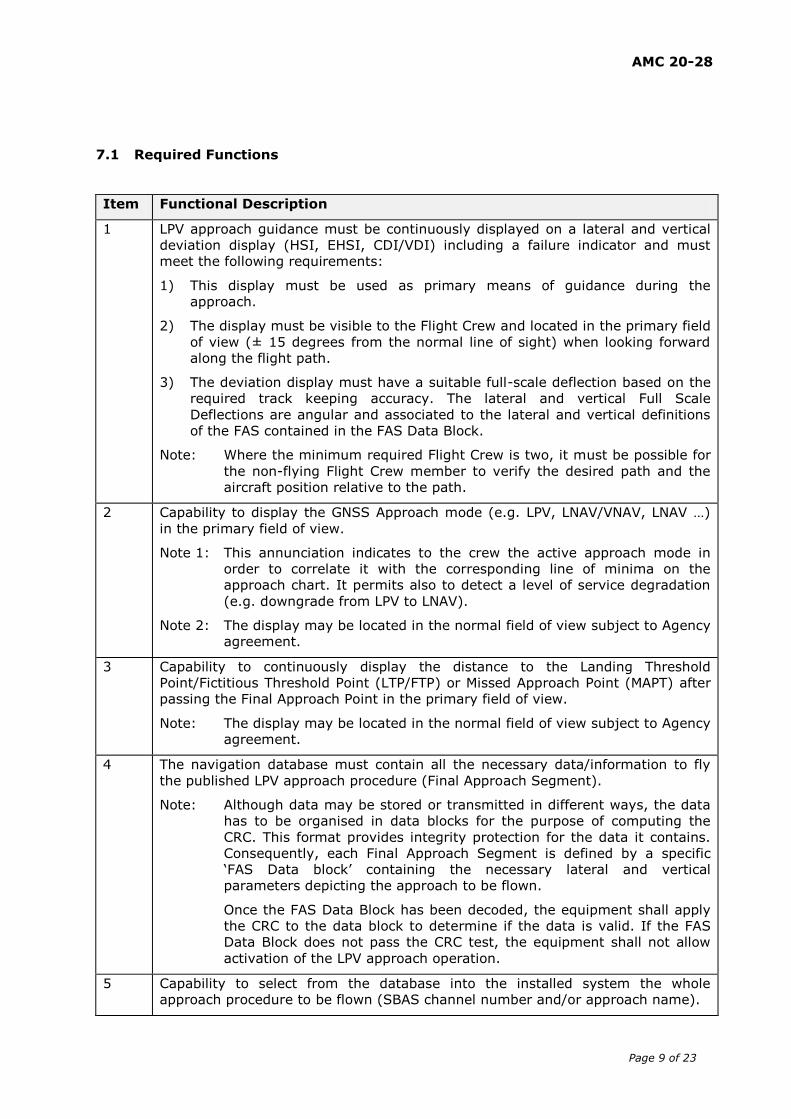
7.1 Required Functions
Item Functional Description
1 LPV approach guidance must be continuously displayed on a lateral and vertical
deviation display (HSI, EHSI, CDI/VDI) including a failure indicator and must
meet the following requirements:
1) This display must be used as primary means of guidance during the
approach.
2) The display must be visible to the Flight Crew and located in the primary field
of view (± 15 degrees from the normal line of sight) when looking forward
along the flight path.
3) The deviation display must have a suitable full-scale deflection based on the
required track keeping accuracy. The lateral and vertical Full Scale
Deflections are angular and associated to the lateral and vertical definitions
of the FAS contained in the FAS Data Block.
Note: Where the minimum required Flight Crew is two, it must be possible for
the non-flying Flight Crew member to verify the desired path and the
aircraft position relative to the path.
2 Capability to display the GNSS Approach mode (e.g. LPV, LNAV/VNAV, LNAV …)
in the primary field of view.
Note 1: This annunciation indicates to the crew the active approach mode in
order to correlate it with the corresponding line of minima on the
approach chart. It permits also to detect a level of service degradation
(e.g. downgrade from LPV to LNAV).
Note 2: The display may be located in the normal field of view subject to Agency
agreement.
3 Capability to continuously display the distance to the Landing Threshold
Point/Fictitious Threshold Point (LTP/FTP) or Missed Approach Point (MAPT) after
passing the Final Approach Point in the primary field of view.
Note: The display may be located in the normal field of view subject to Agency
agreement.
4 The navigation database must contain all the necessary data/information to fly
the published LPV approach procedure (Final Approach Segment).
Note: Although data may be stored or transmitted in different ways, the data
has to be organised in data blocks for the purpose of computing the
CRC. This format provides integrity protection for the data it contains.
Consequently, each Final Approach Segment is defined by a specific
‘FAS Data block’ containing the necessary lateral and vertical
parameters depicting the approach to be flown.
Once the FAS Data Block has been decoded, the equipment shall apply
the CRC to the data block to determine if the data is valid. If the FAS
Data Block does not pass the CRC test, the equipment shall not allow
activation of the LPV approach operation.
5 Capability to select from the database into the installed system the whole
approach procedure to be flown (SBAS channel number and/or approach name).
AMC 20-28
Page 10 of 23
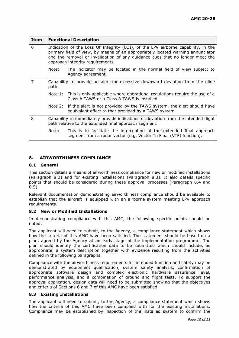
Item Functional Description
6 Indication of the Loss Of Integrity (LOI), of the LPV airborne capability, in the
primary field of view, by means of an appropriately located warning annunciator
and the removal or invalidation of any guidance cues that no longer meet the
approach integrity requirements.
Note: The indicator may be located in the normal field of view subject to
Agency agreement.
7 Capability to provide an alert for excessive downward deviation from the glide
path.
Note 1: This is only applicable where operational regulations require the use of a
Class A TAWS or a Class A TAWS is installed.
Note 2: If the alert is not provided by the TAWS system, the alert should have
equivalent effect to that provided by a TAWS system
8 Capability to immediately provide indications of deviation from the intended flight
path relative to the extended final approach segment.
Note: This is to facilitate the interception of the extended final approach
segment from a radar vector (e.g. Vector To Final (VTF) function).
8. AIRWORTHINESS COMPLIANCE
8.1 General
This section details a means of airworthiness compliance for new or modified installations
(Paragraph 8.2) and for existing installations (Paragraph 8.3). It also details specific
points that should be considered during these approval processes (Paragraph 8.4 and
8.5).
Relevant documentation demonstrating airworthiness compliance should be available to
establish that the aircraft is equipped with an airborne system meeting LPV approach
requirements.
8.2 New or Modified Installations
In demonstrating compliance with this AMC, the following specific points should be
noted:
The applicant will need to submit, to the Agency, a compliance statement which shows
how the criteria of this AMC have been satisfied. The statement should be based on a
plan, agreed by the Agency at an early stage of the implementation programme. The
plan should identify the certification data to be submitted which should include, as
appropriate, a system description together with evidence resulting from the activities
defined in the following paragraphs.
Compliance with the airworthiness requirements for intended function and safety may be
demonstrated by equipment qualification, system safety analysis, confirmation of
appropriate software design and complex electronic hardware assurance level,
performance analysis, and a combination of ground and flight tests. To support the
approval application, design data will need to be submitted showing that the objectives
and criteria of Sections 6 and 7 of this AMC have been satisfied.
8.3 Existing Installations
The applicant will need to submit, to the Agency, a compliance statement which shows
how the criteria of this AMC have been complied with for the existing installations.
Compliance may be established by inspection of the installed system to confirm the
AMC 20-28
Page 11 of 23
availability of required features and functionality. The performance and integrity criteria
of Sections 6 and 7 may be confirmed by reference to statements in the Aircraft Flight
Manual or to other applicable approvals and supporting certification data. In the absence
of such evidence, supplementary analysis and/or tests may be required.
8.4 Specific Installation criteria
The following points need to be taken into consideration during the airworthiness
approval process.
a) Where other conventional navigation/approach systems, apart from the installed
system, provide display and/or guidance to a Flight Director/Autopilot, means
should be provided for:
a system source selector as the only means of selection;
clear annunciation of the selected approach system on or near the guidance
display;
display of guidance information appropriate to the selected approach system;
and
delivery of guidance information to a Flight Director/Autopilot appropriate to
the selected approach system.
b) Annunciation for Flight Director, Autopilot and selected approach system should be
consistent, and compatible with the original design philosophy of the cockpit.
c) Equipment failure scenarios involving conventional navigation/approach systems
and the installed system(s) should be evaluated to demonstrate that:
adequate alternative means of navigation are available following failure of the
installed system, and
reversionary switching arrangements, e.g. Selection of ILS system 2 or LPV
system 2 on HSI#1 in case of multiple (or redundant) equipment, does not
lead to misleading or unsafe display configurations,
adequate means to isolate or deactivate the failed system.
The evaluation should consider also the probability of failures within the switching
arrangements.
d) The coupling arrangements between the installed system and the flight
director/autopilot should be evaluated to show compatibility and to demonstrate
that operating modes, including installed system failure modes, are clearly and
unambiguously indicated to the Flight Crew.
e) The use of the installed system and the manner of presentation of lateral and
vertical guidance information to the Flight Crew should be evaluated to show that
the risk of Flight Crew error has been minimised. The Flight Crew should be aware,
at all times of the system in use for the approach.
f) Controls, displays, operating characteristics and the Flight Crew interface with the
installed system should be assessed in relation to Flight Crew workload, particularly
in the approach environment. Essential design considerations include:
Minimising reliance on Flight Crew memory for any system operating
procedure or task.
Developing a clear and unambiguous display of system modes/sub modes and
navigational data with emphasis on enhanced situational awareness
requirements for any automatic mode changes.
Use of context sensitive help capability and error messages (e.g. invalid inputs
or invalid data entry messages should provide a simple means to determine
AMC 20-28
Page 12 of 23
how to enter ‘valid’ data).
Placing particular emphasis on the number of steps and minimising the time
required to accomplish flight plan modifications to accommodate ATC
clearances, holding procedures, runway and instrument approach changes,
missed approaches and diversions to alternate destinations.
Minimising the number of nuisance alerts so the Flight Crew will recognise and
react appropriately when required.
8.5 Performance evaluation for LPV approach operation
For equipment that complies with paragraph 6.2, the lateral and vertical Full Scale
Deflection (FSD) requirements detailed in RTCA DO-229D ensure a ILS ‘look alike’
presentation. The deflection may be fully angular with no limitation or angular but
bounded at a certain value (e.g. bounded at ± 1 Nm in lateral and ± 150 m in vertical).
The integration of such equipment with display and autopilot system is considered
acceptable if the following criteria are met;
a) Where fully angular deviations are provided and flight display(s) and autopilots
which have not been modified, the applicant should conduct a sufficient number of
approaches while flying raw data, flight director and coupled approaches, as
required to ensure that the installed equipment interfaces are compatible and
enable’s a stable approach and alignment with the runway at all anticipate
distances from the threshold.
b) Where deviations are bounded or the autopilot has been modified, or where the
autopilot lateral/vertical control channel performance has not been assessed, or
where non-standard deviations are provided (not ILS look alike), then the approach
performance will need to comply with the applicable Certification Specification (e.g.
CS xx.1329).
8.6 Intermixing of equipment
Simultaneous use of airborne systems with different crew interfaces can be very
confusing and can lead to problems when they have conflicting methods of operation and
conflicting display formats. For approach operations, simultaneous use of equipment that
is not identical or compatible is not permitted.
9. AIRCRAFT FLIGHT MANUAL/PILOT OPERATING HANDBOOK
For new or modified aircraft, the Aircraft Flight Manual (AFM) or the Pilot’s Operating
Handbook (POH), whichever is applicable, should provide at least the following
information:
a) A statement which identifies the equipment and aircraft build or modification
standard certificated for RNAV GNSS approach operation to LPV minima using
SBAS. This may include a very brief description of the installed system, including
the airborne equipment minimum software version, display equipment and a
statement that it is suitable for LPV approach operations. A brief introduction to the
LPV approach concept may also be included.
b) Appropriate amendments or supplements to cover LPV approach operation in the
following sections:
Limitations - including use of Lateral and Vertical deviations, FD and AP;
currency of navigation database; crew verification of navigation data.
Normal Procedures
Abnormal Procedures - including actions in response to a Loss of Integrity in
response to a degradation of the GNSS approach mode (e.g. downgrade from
LPV to LNAV).
AMC 20-28
Page 13 of 23
Note: This limited set of information assumes that a detailed description of the
installed system and related operating instructions and procedures are
available in other operating or training manuals.
10. OPERATIONAL CRITERIA
This section describes acceptable operational criteria for an LPV approach, subject to the
limitations given below. The operational criteria assume that the corresponding
airworthiness approval has been granted by the Agency.
Operational criteria apply to the use of the approach system on any aircraft operated
under IFR in accordance with EU legislation or the applicable operational regulations in
the fields for which the EU legislation has not yet been established.
Operations of the installed equipment should be in accordance with the AFM or POH. The
operational procedures to be addressed by the operator are detailed in APPENDIX 3. The
Minimum Equipment List (MEL) should be amended if required to identify the minimum
equipment necessary to satisfy LPV approach operations using the installed system.
The operator should determine the operational characteristics of the procedure to be
flown. It is recommended that the process described in paragraph 10.3 and APPENDIX 2
of this AMC should be followed, to validate its operational use by the crew.
Depending on the aircraft capability, an LPV approach may be conducted with either a
flight director or autopilot mode engaged. In this case the ‘approach’ flight guidance
mode should be used.
Prior to LPV approach operation, the operator needs to be authorised or approved by
their competent authority for such operations.
10.1. Flight Operations Documentation
The relevant parts and sections of the Operations Manual (e.g. Aircraft Operations
Manual, check lists, training of crew) should be revised to take account of the operating
procedures detailed in APPENDIX 3. The operator should make timely amendments to
the Operations Manual to reflect relevant procedure and data base checking strategies.
Manuals and check lists may need to be submitted for review by the competent authority
as part of the approval process.
10.2. Flight Crew Training
The Flight Crew should receive appropriate training, briefings and guidance material in
order to safely conduct an LPV approach. This material and training should cover both
normal and abnormal procedures. Standard training and checking should include LPV
approach procedures. Based on this, the operator should determine what constitutes a
qualified crew.
The operator should ensure that during line operations Flight Crew can perform assigned
duties reliably and expeditiously for each procedure to be flown in:
a) normal operations: and
b) abnormal operations.
A training program should be structured to provide sufficient theoretical and practical
training. An example training syllabus is described in APPENDIX 4.
10.3. Aerodrome competence and Operator verification
Before planning a flight to an aerodrome (destination or alternate) with the intent to use
a LPV approach procedure contained in the Navigation Database, the operator should
determine the operational characteristics of the procedure in accordance with EU-OPS
1.975 or the applicable operational regulations. Further details are provided in
APPENDIX 2.
AMC 20-28
Page 14 of 23
Based on this assessment, the appropriate information should be given to the crew. If
the aerodrome access requires a specific competence, the designated crew shall have a
validated competence.
10.4. Navigation Database Management
10.4.1. Operator involved in the operation of aircraft for commercial air
transportation
The operator shall comply with the requirements of EU-OPS 1.873 or applicable
operational regulations for the management of navigation databases.
10.4.2. Operator not involved in the operation of aircraft for commercial air
transportation
The operator shall not use a navigation database for LPV approach operations unless the
navigation database supplier holds a Type 2 Letter of Acceptance (LoA) or equivalent.
An EASA Type 2 LoA is issued by EASA in accordance with EASA OPINION Nr. 01/2005
on ‘The Acceptance of Navigation Database Suppliers’ dated 14 January 2005. The FAA
issues a Type 2 LoA in accordance with AC 20-153, while Transport Canada (TCCA)
issues an Acknowledgement Letter of an Aeronautical Data Process using the same basis.
Both the FAA LoA and the TCCA Acknowledgement Letter are seen to be equivalent to
the EASA LoA.
EUROCAE/RTCA document ED-76/DO-200A Standards for Processing Aeronautical Data
contains guidance relating to the processes that the supplier may follow. The LoA
demonstrates compliance with this standard.
Note 1: The LPV approach is characterised in the navigation database by the FAS Data
Block protected by a CRC. The FAS Data Block contains the lateral and vertical
parameters, which define the approach to be flown. Those parameters have
been calculated, validated and promulgated by the Air Navigation Service
Provider. In addition, each FAS Data Block ends with a CRC, which wraps
around the approach data. Consequently, the integrity is ensured when the
airborne equipment making use of the data successfully passes the CRC on
the data block.
Quality Monitoring
The operator should continue to monitor both the process and the products in
accordance with the quality system required by the applicable operational regulations.
Data Distribution
The operator should implement procedures that ensure timely distribution and insertion
of current and unaltered electronic navigation data to all aircraft that require it.
10.4.3. Reportable Events
A reportable event is one that adversely affects the safety of the operation and may be
caused by actions/events external to the operation of the aircraft navigation system. The
operator should have in place a system for investigating such an event to determine if it
is due to an improperly coded procedure, or a navigation data base error. Responsibility
for initiating corrective action rests with the operator.
For those operators for whom approval is granted under EU-OPS 1, Technical defects and
the exceeding of technical limitations, including the following events, should be the
subject of Occurrence Reports (see EU-OPS 1.420):
a) Significant navigation errors attributed to incorrect data or a database coding error.
b) Unexpected deviations in lateral/vertical flight path not caused by pilot input or
erroneous operation of equipment.
c) Significant misleading information without a failure warning.
AMC 20-28
Page 15 of 23
d) Total loss or multiple navigation equipment failure.
e) Loss of Integrity (LOI) annunciation whereas SBAS for LPV approach operations had
not been notified as unavailable or unreliable during pre-flight planning.
11. AVAILABILITY OF DOCUMENTS
JAA documents are available from the JAA publisher Information Handling Services
(IHS). Information on prices, where and how to order is available on the JAA website:
www.jaa.nl.
EASA documents may be obtained from EASA (European Aviation Safety Agency), PO
Box 101253, D-50452 Koln, Germany. Website: www.easa.europa.eu.
EUROCAE documents may be purchased from EUROCAE, 102 rue Etienne Dolet, 92240
MALAKOFF, France, (Fax: 33 1 46 55 62 65). Website: www.eurocae.eu.
FAA documents may be obtained from Superintendent of Documents, Government
Printing Office, Washington, DC 20402-9325, USA. Website: www.faa.gov/aviation.htm.
RTCA documents may be obtained from RTCA Inc, 1828 L Street, NW, Suite 805,
Washington, DC 20036, USA, (Tel: +1 202 833 9339; Fax: +1 202 833 9434). Website:
www.rtca.org.
ICAO documents may be purchased from Document Sales Unit, International Civil
Aviation Organisation, 999 University Street, Montreal, Quebec, Canada H3C 5H7, (Fax:
+1 514 954 6769, e-mail: [email protected]) or through national agencies.
AMC 20-28
Page 16 of 23
APPENDIX 1: GLOSSARY
The following are definitions of key terms used throughout this AMC.
Abnormal procedure: Crew procedure defined in the AFM or POH to address Warnings
and Cautions issued by aircraft systems
Aircraft-Based Augmentation System (ABAS): An augmentation system that
augments and/or integrates the information obtained from the other GNSS elements
with information available on board the aircraft.
Area navigation (RNAV): A method of navigation which permits aircraft operation on
any desired flight path within the coverage of station-referenced navigation aids or
within the limits of the capability of self-contained aids, or a combination of these.
Accuracy: The degree of conformance between the estimated, measured, or desired
position and/or the velocity of a platform at a given time, and its true position or
velocity. Navigation performance accuracy is usually presented as a statistical measure
of system error and is specified as predictable, repeatable and relative.
Availability: An indication of the ability of the system to provide usable service within
the specified coverage area and is defined as the portion of time during which the
system is to be used for navigation during which reliable navigation information is
presented to the crew, autopilot, or other system managing the flight of the aircraft.
Contingency Procedures: A procedure developed by the operator to address a
situation where the intended procedure could not be performed.
Continuity of Function: The capability of the total system (comprising all elements
necessary to maintain aircraft position within the defined airspace) to perform its
function without non-scheduled interruptions during the intended operation.
Cyclic Redundancy Check (CRC): A mathematical algorithm applied to the digital
expression of data that provides a level of assurance against loss or alteration of data.
DA(H): Decision altitude (DA) or Decision height (DH). A specified altitude or height in
the precision approach or approach with vertical guidance at which a missed approach
must be initiated if the required visual reference to continue the approach has not been
established
FAP: Final Approach Point.
FSD: Full Scale Deflection
FTP: Fictitious Threshold Point. The threshold location is referred to as the FTP when it is
displaced from the runway. FTP coordinates are stored in the FAS Data Block (see also
RTCA DO-229( )).
GNSS stand-alone receiver: A GNSS system incorporating the GNSS sensor, the
navigation capability and the navigation data base.
GNSS sensor: A GNSS system incorporating only the GNSS receiving and positioning
part. It doesn’t incorporate the navigation capability and the navigation data base.
GPA: Glidepath Angle: It represents the angle of the approach path (glide path) with
respect to the horizontal plane defined according to WGS-84 at the LTP/FTP. GPA is
stored in the FAS data block (see also RTCA DO-229( )).
HAL: Horizontal Alert Limit.
ILS Look alike: ‘ILS Look alike’ is defined as the ability of a non-ILS based navigation
receiver function to provide operational characteristics and interface functionality to the
rest of the aircraft equivalent to that provided by an ILS based receiver function.
AMC 20-28
Page 17 of 23
Integrity: The ability of a system to provide timely warnings to users when the system
should not be used for navigation.
LPV: Localiser Performance with Vertical guidance.
LPV approach operation: RNAV GNSS approach operation conducted down to LPV
minima.
LPV approach procedure: RNAV GNSS approach procedure containing LPV minima.
LPV approach capability: Airborne capability to fly LPV approach procedure.
LPV OCA(H): Obstacle clearance altitude (OCA) or obstacle clearance height (OCH). The
lowest altitude or the lowest height above the elevation of the relevant runway threshold
or the aerodrome elevation as applicable, used in establishing compliance with
appropriate obstacle clearance criteria.
LTP: Landing Threshold Point. The threshold location is referred to as the LTP when it is
collocated with the runway. LTP coordinates are stored in the FAS Data Block.
RNAV System: A navigation system which permits aircraft operation on any desired
flight path within the coverage of station-referenced navigation aids or within the limits
of the capability of self-contained aids, or a combination of these. A RNAV system may
be included as part of a Flight Management System (FMS).
RNAV(GNSS) approach: A GNSS RNAV approach promulgated by a state and designed
in accordance with PANS-OPS Criteria ICAO Doc 8168.
SBAS: Satellite Based Augmentation System. SBAS augments core satellite constellation
by providing ranging, integrity and correction information via geostationary satellites.
This system comprises a network of ground reference stations that observe satellites
signals, and master stations that process observed data and generate SBAS messages
for uplink to the geostationary satellites, which broadcast the SBAS message to the
users.
RNP APCH: RNP AProaCH. A RNP approach defined in the ICAO Performance Based
Manual (PBN) manual.
ETSO: European Technical Standard Order.
Vertical Navigation: A method of navigation which permits aircraft operation on a
vertical flight profile using altimetry sources, external flight path references, or a
combination of these.
VTF: Vector To Final.
AMC 20-28
Page 18 of 23
APPENDIX 2: OPERATIONAL CHARACTERISTICS OF THE PROCEDURE AND ITS
OPERATIONAL USE
Depending upon the type of operation being undertaken the operator should consider the
following:
a) The provision of evidence of an evaluation of any new or modified LPV approach
procedures. Particular attention should be paid to procedures:
in mountainous environment;
within the proximity of well-known obstacles; and
that may require adequate knowledge for the aerodrome access or aerodrome
competence qualification, as specified in EU-OPS 1.975 or the applicable
operational requirements.
b) That competence may be required specifically for an LPV approach procedure or
the procedure may be published for an aerodrome already listed as requiring an
aerodrome competence. The required competence may be aircraft type related
and subject to periodic revalidation. Particular attention should be paid to
procedures that:
are not in radar coverage;
have a missed approach trajectories involving turns, especially at low altitudes;
are subject to a declared exemption to the procedure design rules specified by
the ICAO PANS OPS; and
every other case considered necessary to be evaluated by the operator.
c) The development of an internal process (e.g. filtering methods or tools covering
the AIP review) to detect LPV approach procedure(s) showing one or more of the
above-listed characteristics.
d) The operational evaluation of a LPV approach procedure showing evidence of the
above mentioned operational characteristics which may include, at operator
discretion, an approach conducted with the aircraft in VMC or the use of a full
flight simulator (FFS) in order to evaluate if the procedure is correctly executed
by the navigation system and fly-able with the aircraft type.
AMC 20-28
Page 19 of 23
APPENDIX 3: LPV APPROACH OPERATIONAL PROCEDURES
This appendix should be used by the operator to amend operational manual(s) to
support LPV approach operation.
1. Normal Procedures
1.1 Pre-flight Planning
The on board navigation data must be current and must include the appropriate
procedures.
In addition to the normal pre-flight planning the following checks must be carried out:
a) The instrument approach chart should clearly identify the LPV approach operation
as RNAV(GNSS) to LPV minima. The operator should determine in accordance with
the promulgated OCA(H) and the operational requirement (e.g. EU-OPS 1.430) the
Decision Altitude/Height (DA(H)).
b) The Flight Crew must ensure that LPV approach procedures which may be used for
the intended flight (including alternate aerodromes) are selectable from a valid
navigation data base (current AIRAC cycle) and are not prohibited by a company
instruction or NOTAM.
The Flight Crew could check approach procedures (including alternate aerodromes)
as extracted by the system (e.g. CDU flight plan page) or presented graphically on
the NAV display, in order to confirm the correct loading and the reasonableness of
the procedure content. The vertical path of the LPV approach procedure could be
checked as extracted from the navigation database on the system Man Machine
Interface (e.g. CDU).
If above verification is not satisfactory, the Flight Crew should not use the
procedure, and not consider this(ese) approach(es) during the selection of
aerodromes for the intended flight.
Note: For LPV approach operations, the Flight Crew selects the desired approach
procedure using its name or the SBAS channel number and the on board
system automatically extracts the high-integrity procedure and associated
alert limits (VAL, HAL). This information is protected from data corruption
by a cyclic redundancy check (CRC) determined during the procedure
design.
c) The Flight Crew should ensure sufficient means are available to navigate and land
at the destination or at an alternate aerodrome in the case of loss of the capability
to perform RNAV(GNSS) approaches to the published minima.
d) Operators and Flight-Crews must take account of any NOTAMs (including SBAS
NOTAMs) or operator briefing material that could adversely affect the aircraft
system operation, or the availability or suitability of the procedures at the airport of
landing, or any alternate airport.
e) If the missed approach procedure is based on conventional means (e.g. VOR, DME)
the appropriate airborne equipment required to fly this procedure must be available
and serviceable on board the aircraft. The associated ground-based navigation aids
must also be operational.
If the missed approach procedure is based on RNAV (no conventional or dead
reckoning missed approach available) the appropriate airborne equipment required
to fly this procedure must be available and serviceable on board the aircraft.
f) Any MEL restriction must be observed.
AMC 20-28
Page 20 of 23
1.2 Prior to Commencing the Procedure
The Final approach segment (FAS) of an LPV approach procedure may be intercepted by
an approach transition (e.g. P-RNAV or initial/intermediate segments of an RNP APCH
approach) or through vectoring (interception of the extended Final approach segment
following ATC instruction).
In addition to normal procedure prior to commencing the approach (before the IAF and
in compatibility with crew workload), the Flight Crew must verify the correctness of the
loaded procedure by comparison with the appropriate approach charts. This check must
include:
The waypoint sequence;
Reasonableness of the tracks and distances of the approach legs, and the
accuracy of the inbound course and mileage of the final approach segment.
Note: As a minimum, this check could be a simple inspection of a suitable map
display.
The vertical path angle where the system permits.
ATC tactical interventions in the terminal area may include radar headings, ‘direct to’
clearances which by-pass the initial legs of an approach, interception of an initial or
intermediate segment of an approach or the insertion of waypoints loaded from the
database. In complying with ATC instructions, the Flight Crew should be aware of the
implications for the navigation system in particular:
the manual entry of coordinates into the navigation system by the Flight Crew
for operation within the terminal area is not permitted;
‘Direct to’ clearances may be accepted to the Intermediate Fix (IF) provided
that the resulting track change at the IF does not exceed 45o.
Note: Direct to clearance to FAP is not acceptable.
The approach system provides the capability for the Flight Crew to intercept the Final
Approach track well before the FAP (Vector To Final (VTF) function or equivalent). This
function should be used to respect a given ATC clearance.
1.3 During the Procedure
The system provides lateral and vertical guidance relative to the LPV Final Approach
Segment or to the extended final approach segment (for the direct transition).
The crew must check that the GNSS approach mode indicates LPV (or an equivalent
annunciation) prior to passing the FAP.
The final approach segment should be intercepted before the FAP in order for the aircraft
to be correctly established on the final approach course before starting the descent (to
ensure terrain and obstacle clearance). The appropriate displays should be selected so
that the following information can be monitored:
aircraft position relative to the lateral path;
aircraft position relative to the vertical path;
absence of LOI (Loss Of Integrity) alert.
The crew should respect all published altitude and speed constraints.
The Flight Crew shall maintain the aircraft within ⅓ the full scale deflection for the lateral
deviation and within ½ the full scale deflection for the vertical deviation.
Prior to sequencing the FAP, the procedure must be discontinued or may be continued to
LNAV minima when supported by the system if there is:
AMC 20-28
Page 21 of 23
loss of integrity is indicated by a warning annunciator (e.g. absence of power,
equipment failure).
After sequencing the FAP, the procedure must be discontinued, unless the Flight Crew
have in sight the visual references required to continue the approach if there is:
loss of integrity is indicated by a warning annunciator;
loss of vertical guidance is indicated (even if lateral guidance is displayed);
lateral or vertical deviation are excessive and cannot be timely corrected.
The missed approach must be flown in accordance with the published procedure (e.g.
conventional or RNAV).
Note: Alternatively, when the aircraft is still above 1 000 ft. AGL, the pilot may
decide to continue the approach to LNAV minima when supported by the
system.
2. Abnormal Procedures
Abnormal procedures to address Cautions and Warnings resulting from the following
conditions should be developed:
Failure of the navigation system components, including those affecting flight
technical errors (e.g. failures of the flight director or autopilot).
Loss of integrity annunciation.
Warning flag or equivalent indicator on the lateral and/or vertical navigation
display.
Degradation of the GNSS approach mode during a LPV approach procedure (e.g.
downgrade from LPV to LNAV).
In case of a complete RNAV guidance loss during the approach, the crew must follow the
operator defined contingency procedure.
In the event of communications failure, the Flight Crew should continue with the
procedure in accordance with published lost communication procedures.
The Flight Crew should notify ATC of any problem with the navigation system that results
in the loss of the approach capability.
AMC 20-28
Page 22 of 23
APPENDIX 4: FLIGHT CREW TRAINING SYLLABUS
The Flight Crew training program should be structured to provide sufficient theoretical
and practical training, using a simulator, training device, or line training in an aircraft, in
the concept of RNAV GNSS approach operations to LPV minima and the use of the
aircraft’s approach system in such operations to ensure that Flight Crew are not just task
oriented. The following syllabus should be considered as a minimum amendment to the
training programme to support these operations:
1. RNAV APPROACH CONCEPT CONTAINING LPV MINIMA:
a) Theory of approach operations;
b) Approach charting;
c) Use of the approach system including:
i. Selection of the LPV approach procedure;
ii. ILS look alike principle.
d) Use of lateral navigation mode(s) and associated lateral control techniques;
e) Use of vertical navigation mode(s) and associated vertical control techniques;
f) R/T phraseology for LPV approach operations;
g) The implication for LPV approach operations of systems malfunctions which are not
related to the approach system (e.g. hydraulic or engine failure).
2. RNAV APPROACH OPERATION CONTAINING LPV MINIMA:
a) Definition of LPV approach operations and its direct relationship with RNAV(GNSS)
procedures;
b) Regulatory requirements for LPV approach operations;
c) Required navigation equipment for LPV approach operations:
i. GNSS concepts and characteristics;
ii. SBAS augmentation and characteristics;
iii. MEL.
d) Procedure characteristics:
i. Chart depiction;
ii. Aircraft display depiction;
iii. Minima.
e) Retrieving a LPV approach procedure from the database (e.g. using its name or the
SBAS channel number);
f) Procedure change at destination airport, change arrival airport and alternate
airport;
g) Flying the procedure:
i. Use of autopilot, autothrottle and flight director;
ii. Flight Guidance(FG) mode behaviour;
iii. Lateral and vertical path management;
AMC 20-28
Page 23 of 23
iv. Adherence to speed and/or altitude constraints;
v. Fly interception of an initial or intermediate segment of an approach following
ATC notification;
vi. Fly interception of the extended final approach segment (e.g. using the VTF
function);
vii. Consideration of the GNSS approach mode indication (LPV, LNAV/VNAV,
LNAV,…);
viii. Reversion to LNAV minima;
ix. The use of other aircraft equipment to support track monitoring, weather and
obstacle avoidance.
h) ATC procedures;
i) Abnormal procedures;
j) Contingency procedures.