annex 10, volume iii - dyn 10 - aeronautical... · annex 10 — aeronautical telecommunications...
TRANSCRIPT


AMENDMENTS
The issue of amendments is announced regularly in the ICAO Journal and in themonthly Supplement to the Catalogue of ICAO Publications and Audio-visualTraining Aids, which holders of this publication should consult. The space belowis provided to keep a record of such amendments.
RECORD OF AMENDMENTS AND CORRIGENDA
AMENDMENTS CORRIGENDA
No.Date
applicableDate
enteredEntered
by No.Date
of issueDate
enteredEntered
by
71 7/11/96 — ICAO
72 6/11/97 — ICAO
73 5/11/98 — ICAO
74 4/11/99 — ICAO
75 2/11/00 — ICAO
76 1/11/01 — ICAO
77 28/11/02 — ICAO
78 27/11/03 — ICAO
79 25/11/04 — ICAO
80 24/11/05 — ICAO
(ii)
ANNEX 10 — VOLUME III (iii) 5/11/9528/11/02
No. 77
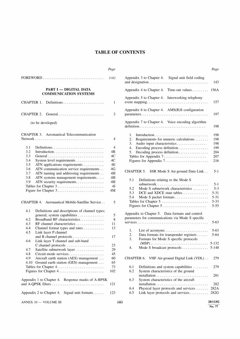
TABLE OF CONTENTS
Page Page
FOREWORD . . . . . . . . . . . . . . . . . . . . . . . . . . . . . . . . . (vii)
PART I — DIGITAL DATACOMMUNICATION SYSTEMS
CHAPTER 1. Definitions . . . . . . . . . . . . . . . . . . . . . . 1
CHAPTER 2. General. . . . . . . . . . . . . . . . . . . . . . . . . 3
(to be developed)
CHAPTER 3. Aeronautical TelecommunicationNetwork . . . . . . . . . . . . . . . . . . . . . . . . . . . . . . . . . . . . . 4
3.1 Definitions. . . . . . . . . . . . . . . . . . . . . . . . . . . . 43.2 Introduction. . . . . . . . . . . . . . . . . . . . . . . . . . . 4B3.3 General . . . . . . . . . . . . . . . . . . . . . . . . . . . . . . 4C3.4 System level requirements . . . . . . . . . . . . . . . 4C3.5 ATN applications requirements . . . . . . . . . . . 4E3.6 ATN communication service requirements . . 4G3.7 ATN naming and addressing requirements . . 4H3.8 ATN systems management requirements . . . . 4H3.9 ATN security requirements. . . . . . . . . . . . . . . 4HTables for Chapter 3 . . . . . . . . . . . . . . . . . . . . . . . . . 4JFigure for Chapter 3 . . . . . . . . . . . . . . . . . . . . . . . . . 4M
CHAPTER 4. Aeronautical Mobile-Satellite Service . . 5
4.1 Definitions and descriptions of channel types;general; system capabilities . . . . . . . . . . . . . . 5
4.2 Broadband RF characteristics. . . . . . . . . . . . . 84.3 RF channel characteristics . . . . . . . . . . . . . . . 114.4 Channel format types and rates . . . . . . . . . . . 134.5 Link layer P channel
and R channel protocols . . . . . . . . . . . . . . . . . 174.6 Link layer T channel and sub-band
C channel protocols . . . . . . . . . . . . . . . . . . . . 234.7 Satellite subnetwork layer . . . . . . . . . . . . . . . 294.8 Circuit-mode services . . . . . . . . . . . . . . . . . . . 454.9 Aircraft earth station (AES) management . . . 604.10 Ground earth station (GES) management . . . 65Tables for Chapter 4 . . . . . . . . . . . . . . . . . . . . . . . . . 73Figures for Chapter 4 . . . . . . . . . . . . . . . . . . . . . . . . 102
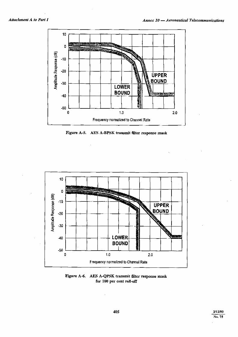
Appendix 1 to Chapter 4. Response masks of A-BPSK and A-QPSK filters . . . . . . . . . . . . . . . . . . . . . . . . . . . . 121
Appendix 2 to Chapter 4. Signal unit formats. . . . . . 123
Appendix 3 to Chapter 4. Signal unit field coding and designation . . . . . . . . . . . . . . . . . . . . . . . . . . . . . . . . 143
Appendix 4 to Chapter 4. Time-out values. . . . . . . . . 156A
Appendix 5 to Chapter 4. Interworking telephony event mapping. . . . . . . . . . . . . . . . . . . . . . . . . . . . . . . . . 157
Appendix 6 to Chapter 4. AMS(R)S configuration parameters . . . . . . . . . . . . . . . . . . . . . . . . . . . . . . . . . . . . 197
Appendix 7 to Chapter 4. Voice encoding algorithm definition . . . . . . . . . . . . . . . . . . . . . . . . . . . . . . . . . . . . . 198
1. Introduction. . . . . . . . . . . . . . . . . . . . . . . . . . . . . 1982. Requirements for numeric calculations . . . . . . . 1983. Audio input characteristics . . . . . . . . . . . . . . . . . 1984. Encoding process definition . . . . . . . . . . . . . . . . 1995. Decoding process definition . . . . . . . . . . . . . . . . 204Tables for Appendix 7 . . . . . . . . . . . . . . . . . . . . . . . . 207Figures for Appendix 7 . . . . . . . . . . . . . . . . . . . . . . . 216
CHAPTER 5. SSR Mode S Air-ground Data Link . . 5-1
5.1 Definitions relating to the Mode S subnetwork. . . . . . . . . . . . . . . . . . . . . . . . . . . . 5-1
5.2 Mode S subnetwork characteristics . . . . . . . . 5-35.3 DCE and XDCE state tables. . . . . . . . . . . . . . 5-315.4 Mode S packet formats . . . . . . . . . . . . . . . . . . 5-31Tables for Chapter 5 . . . . . . . . . . . . . . . . . . . . . . . . . 5-33Figures for Chapter 5 . . . . . . . . . . . . . . . . . . . . . . . . 5-55
Appendix to Chapter 5. Data formats and controlparameters for communications via Mode S specificservices . . . . . . . . . . . . . . . . . . . . . . . . . . . . . . . . . . . . . . 5-63
1. List of acronyms . . . . . . . . . . . . . . . . . . . . . . . 5-632. Data formats for transponder registers . . . . . . 5-643. Formats for Mode S specific protocols
(MSP) . . . . . . . . . . . . . . . . . . . . . . . . . . . . . . . 5-1324. Mode S broadcast protocols . . . . . . . . . . . . . . 5-148
CHAPTER 6. VHF Air-ground Digital Link (VDL) . . 279
6.1 Definitions and system capabilities . . . . . . . . 2796.2 System characteristics of the ground
installation . . . . . . . . . . . . . . . . . . . . . . . . . . . . 2816.3 System characteristics of the aircraft
installation . . . . . . . . . . . . . . . . . . . . . . . . . . . . 2826.4 Physical layer protocols and services . . . . . . . 282A6.5 Link layer protocols and services . . . . . . . . . . 282G

Annex 10 — Aeronautical Telecommunications Volume III
5/11/95 (iv)
Page Page
28/11/02
No. 77
6.6 Subnetwork layer protocols and services . . . 282H6.7 The VDL mobile subnetwork dependent
convergence function (SNDCF). . . . . . . . . . . 282H6.8 Voice unit for Mode 3 . . . . . . . . . . . . . . . . . . 282I6.9 VDL Mode 4 . . . . . . . . . . . . . . . . . . . . . . . . . 282ITables for Chapter 6 . . . . . . . . . . . . . . . . . . . . . . . . . 282NFigures for Chapter 6 . . . . . . . . . . . . . . . . . . . . . . . . 282P
Appendix to Chapter 6. References . . . . . . . . . . . . . . 282R
CHAPTER 7. Subnetwork Interconnection . . . . . . . . 282S
(to be developed)
CHAPTER 8. AFTN Network . . . . . . . . . . . . . . . . . . 283
8.1 Definitions. . . . . . . . . . . . . . . . . . . . . . . . . . . . 2838.2 Technical provisions relating to
teletypewriter apparatus and circuitsused in the AFTN. . . . . . . . . . . . . . . . . . . . . . 283
8.3 Terminal equipment associated withaeronautical radioteletypewriter channelsoperating in the band 2.5 – 30 MHz . . . . . . . 285
8.4 Characteristics of interregionalAFS circuits . . . . . . . . . . . . . . . . . . . . . . . . . . 285
8.5 Technical provisions relating to ATSmessage transmission . . . . . . . . . . . . . . . . . . . 286
8.6 Technical provisions relating to internationalground-ground data interchange at mediumand higher signalling rates . . . . . . . . . . . . . . . 286
CHAPTER 9. Aircraft Addressing System . . . . . . . . 329
Appendix to Chapter 9. A World-wide Schemefor the Allocation, Assignment and Applicationof Aircraft Addresses. . . . . . . . . . . . . . . . . . . . . . . . . . . 330
1. General . . . . . . . . . . . . . . . . . . . . . . . . . . . . . . 3302. Description of the scheme . . . . . . . . . . . . . . . 3303. Management of the scheme . . . . . . . . . . . . . . 3304. Allocation of aircraft addresses . . . . . . . . . . . 3305. Assignment of aircraft addresses . . . . . . . . . . 3306. Application of aircraft addresses . . . . . . . . . . 3317. Administration of the temporary aircraft
address assignments . . . . . . . . . . . . . . . . . . . . 331Table 9-1. Allocation of aircraft addressesto States. . . . . . . . . . . . . . . . . . . . . . . . . . . . . . 332
CHAPTER 10. Point-to-MultipointCommunications . . . . . . . . . . . . . . . . . . . . . . . . . . . . . . 337
10.1 Service via satellite for the disseminationof aeronautical information . . . . . . . . . . . . . . 337
10.2 Service via satellite for the dissemination ofWAFS products . . . . . . . . . . . . . . . . . . . . . . . 337
CHAPTER 11 HF Data Link . . . . . . . . . . . . . . . . . . . 338
11.1 Definitions and system capabilities . . . . . . . . 33811.2 HF data link system . . . . . . . . . . . . . . . . . . . . 33811.3 HF data link protocol . . . . . . . . . . . . . . . . . . . 338A11.4 Ground management sub-system . . . . . . . . . . 338F
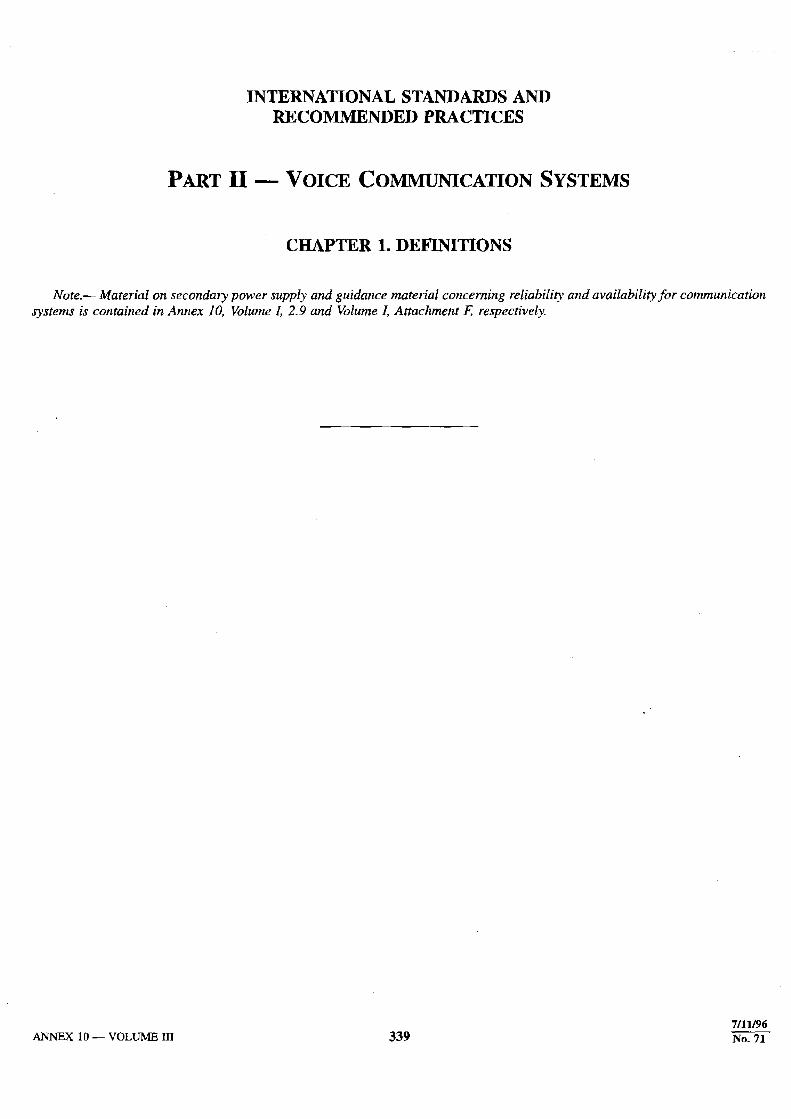
PART II — VOICE COMMUNICATIONSYSTEMS
CHAPTER 1. Definitions . . . . . . . . . . . . . . . . . . . . . . 339
CHAPTER 2. Aeronautical Mobile Service . . . . . . . . 340
2.1 Air-ground VHF communication systemcharacteristics . . . . . . . . . . . . . . . . . . . . . . . . . 340
2.2 System characteristics of the groundinstallation . . . . . . . . . . . . . . . . . . . . . . . . . . . . 340
2.3 System characteristics of the airborneinstallation . . . . . . . . . . . . . . . . . . . . . . . . . . . . 341
2.4 Single sideband (SSB) HF communicationsystem characteristics for use in theaeronautical mobile service. . . . . . . . . . . . . . . 343
CHAPTER 3. SELCAL System . . . . . . . . . . . . . . . . . 348
CHAPTER 4. Aeronautical Speech Circuits . . . . . . . 349
4.1 Technical provisions relating to internationalaeronautical speech circuit switching andsignalling for ground-ground applications . . . 349
CHAPTER 5. Emergency Locator Transmitter (ELT)for Search and Rescue . . . . . . . . . . . . . . . . . . . . . . . . . . 350
5.1 General. . . . . . . . . . . . . . . . . . . . . . . . . . . . . . . 3505.2 Specification for the 121.5 MHz component
of emergency locator transmitters (ELT)for search and rescue. . . . . . . . . . . . . . . . . . . . 350
5.3 Specification for the 406 MHz componentof emergency locator transmitters (ELT)for search and rescue. . . . . . . . . . . . . . . . . . . . 351
Appendix 1 to Chapter 5. Emergency LocatorTransmitter Coding. . . . . . . . . . . . . . . . . . . . . . . . . . . . . 353
1. General. . . . . . . . . . . . . . . . . . . . . . . . . . . . . . . 3532. ELT coding . . . . . . . . . . . . . . . . . . . . . . . . . . . 353
ATTACHMENTS
Attachment A to Part I — Guidance material foraeronautical mobile-satellite service . . . . . . . . . . . . . . . 357
25/11/04
No. 79

Table of Contents Annex 10 — Aeronautical Telecommunications
(v) 5/11/95
Page Page
28/11/02
No. 77
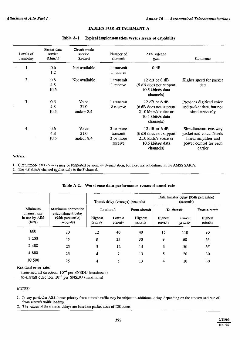
1. Introduction. . . . . . . . . . . . . . . . . . . . . . . . . . . 3571.1 Overview. . . . . . . . . . . . . . . . . . . . . . . . 3571.2 Levels of capability . . . . . . . . . . . . . . . 357
2. Broadband RF characteristics. . . . . . . . . . . . . 3582.1 Use of AMS(R)S bands . . . . . . . . . . . . 3582.2 Frequency accuracy and
compensation . . . . . . . . . . . . . . . . . . . . 3582.3 Aircraft earth station antenna
characteristics . . . . . . . . . . . . . . . . . . . . 3592.4 Receiver requirements . . . . . . . . . . . . . 3592.5 Transmitter requirements . . . . . . . . . . . 3602.6 Interference . . . . . . . . . . . . . . . . . . . . . . 361
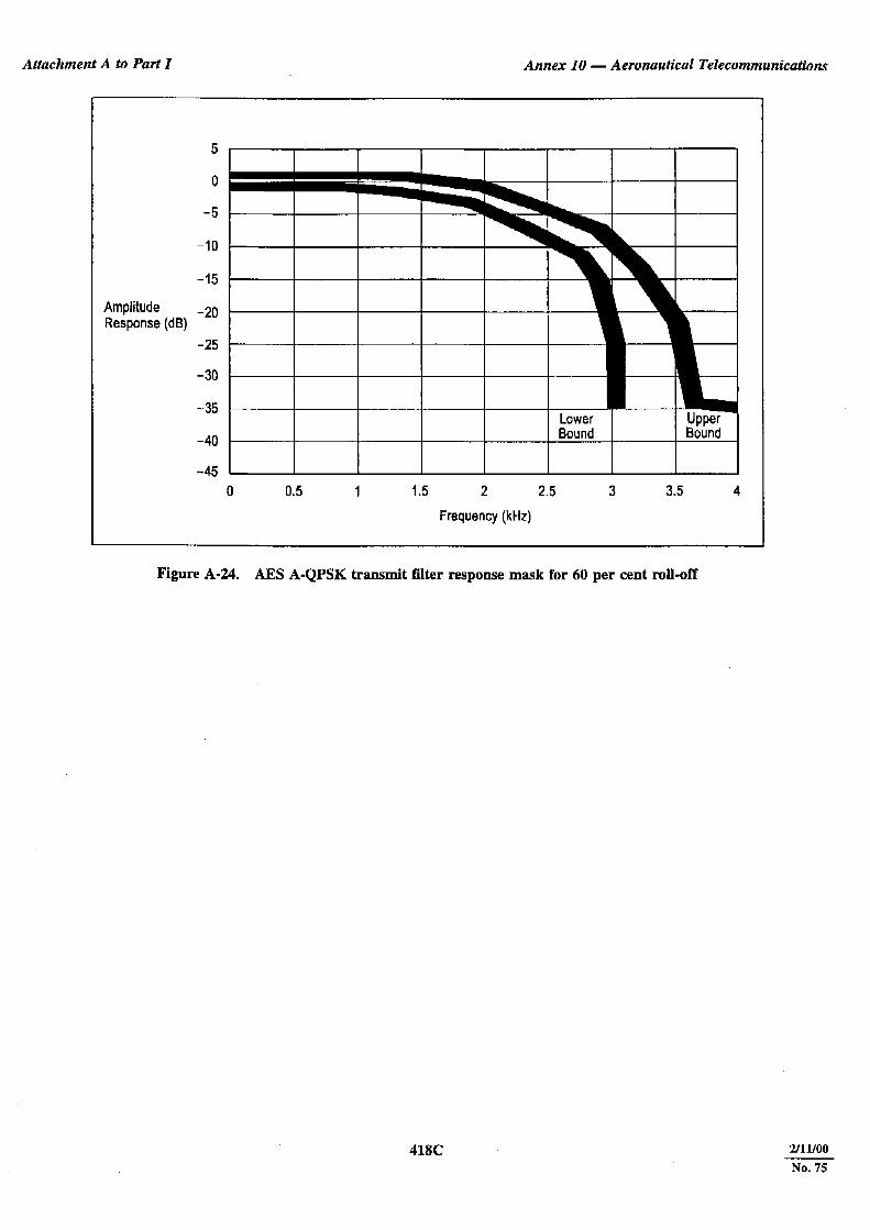
3. RF channel characteristics . . . . . . . . . . . . . . . 3623.1 Modulation characteristics . . . . . . . . . . 3623.2 Bounds on radiated power spectral
density. . . . . . . . . . . . . . . . . . . . . . . . . . 3623.3 Demodulator performance . . . . . . . . . . 3633.4 Acquisition delay . . . . . . . . . . . . . . . . . 363
4. Channel format types and data rate . . . . . . . . 3634.1 General . . . . . . . . . . . . . . . . . . . . . . . . . 3634.2 P channel . . . . . . . . . . . . . . . . . . . . . . . 3644.3 R channel . . . . . . . . . . . . . . . . . . . . . . . 3644.4 T channel . . . . . . . . . . . . . . . . . . . . . . . 3654.5 C channel . . . . . . . . . . . . . . . . . . . . . . . 365
5. Link layer P channel and R channel protocols . . . . . . . . . . . . . . . . . . . . . . . . . . . . . 3665.1 General . . . . . . . . . . . . . . . . . . . . . . . . . 3665.2 SU set generation . . . . . . . . . . . . . . . . . 3675.3 SUs transmission according to
precedence . . . . . . . . . . . . . . . . . . . . . . 3675.4 P channel protocol . . . . . . . . . . . . . . . . 3675.5 R channel protocol . . . . . . . . . . . . . . . . 368
6. Link layer T channel and sub-band C channel protocols . . . . . . . . . . . . . . . . . . . . 3686.1 General . . . . . . . . . . . . . . . . . . . . . . . . . 3686.2 SU set generation . . . . . . . . . . . . . . . . . 3686.3 T channel transmission protocol . . . . . 3696.4 T channel reservation protocol . . . . . . . 3706.5 Sub-band C channel to-aircraft and
from-aircraft protocol . . . . . . . . . . . . . . 3727. Satellite subnetwork layer . . . . . . . . . . . . . . . 372
7.1 General provisions . . . . . . . . . . . . . . . . 3727.2 Packet data performance . . . . . . . . . . . 3737.3 Satellite subnetwork dependent protocol
services and operations. . . . . . . . . . . . . 3757.4 ISO 8208 DCE protocol operations. . . 3787.5 Management interface . . . . . . . . . . . . . 378
8. Circuit-mode services . . . . . . . . . . . . . . . . . . . 3788.1 Circuit-mode voice signalling
protocols . . . . . . . . . . . . . . . . . . . . . . . . 3788.2 Interworking of circuit-mode services
with other voice networks . . . . . . . . . . 3808.3 Implementing satellite voice in the
ATS environment . . . . . . . . . . . . . . . . . 3818.4 Terrestrial voice network
considerations . . . . . . . . . . . . . . . . . . . . 383
8.5 Implementing the group call/broadcastfunctions . . . . . . . . . . . . . . . . . . . . . . . . 384
8.6 Implementing the call registration function . . . . . . . . . . . . . . . . . . . . . . . . . 384
8.7 Notes on the abbreviated air-origination procedure. . . . . . . . . . . . 385
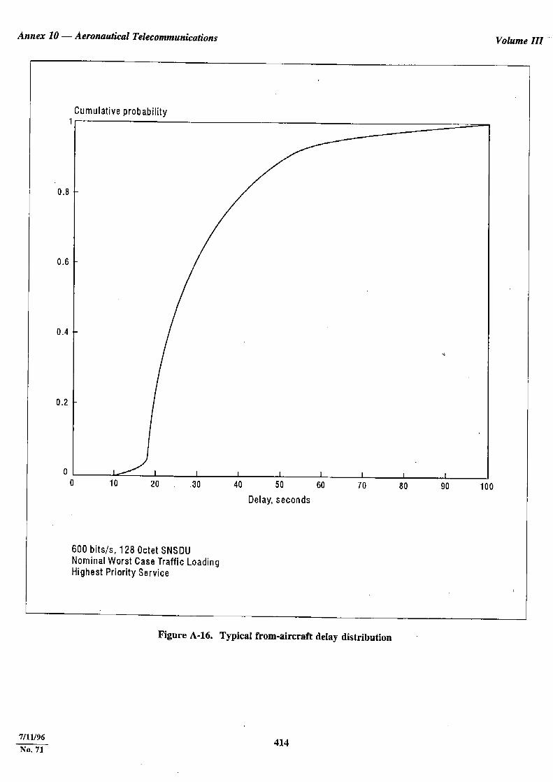
8.8 Circuit-mode access delay performance . . . . . . . . . . . . . . . . . . . . . . 385
8.9 Subjective voice quality evaluation . . . 3869. Aircraft earth station (AES) management . . . 387
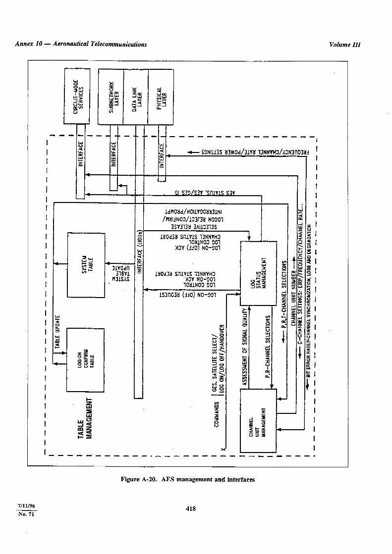
9.1 General. . . . . . . . . . . . . . . . . . . . . . . . . . 3879.2 AES management interfaces . . . . . . . . . 3879.3 AES management functions . . . . . . . . . 387
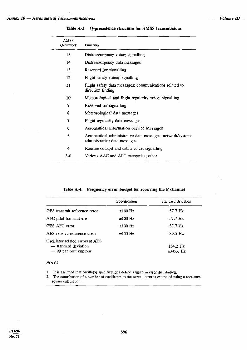
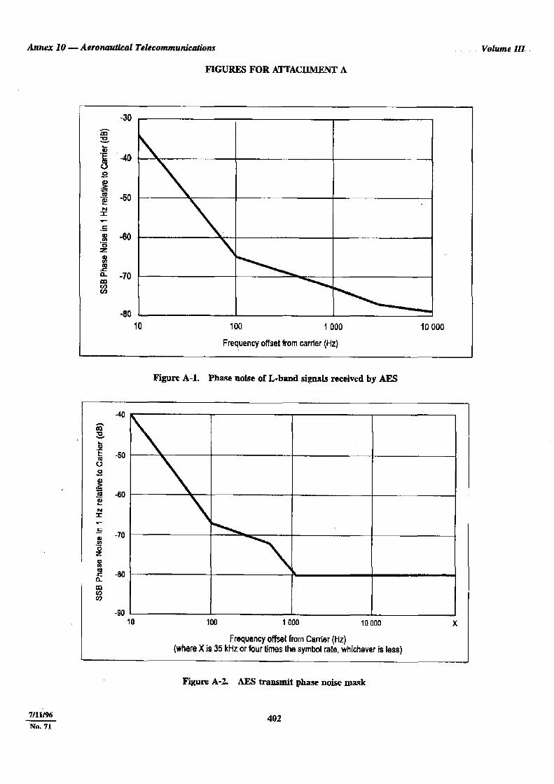
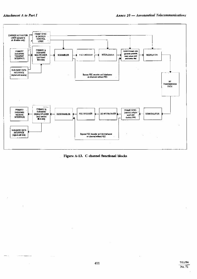
10. Ground earth station (GES) management. . . . 38910.1 General. . . . . . . . . . . . . . . . . . . . . . . . . . 38910.2 GES management architecture . . . . . . . 38910.3 GES management interfaces . . . . . . . . . 39010.4 GES management functions . . . . . . . . . 39010.5 Considerations for GES services . . . . . 393Tables for Attachment A. . . . . . . . . . . . . . . . . 395Figures for Attachment A . . . . . . . . . . . . . . . . 402Appendix to Attachment A. Performance analysis . . . . . . . . . . . . . . . . . . . . . . . . . . . . . . 419
Attachment B to Part I — Guidance material for the VHF Digital Link (VDL)
1. Guidance material for the VHF digital link (VDL) . . . . . . . . . . . . . . . . . . . . . . . . . . . . . . . 423
2. System description . . . . . . . . . . . . . . . . . . . . . 4233. VDL principles . . . . . . . . . . . . . . . . . . . . . . . . 423
3.1 Communications transfer principles . . . 4233.2 VDL quality of service for ATN
routing . . . . . . . . . . . . . . . . . . . . . . . . . . 4244. VDL ground station network concept . . . . . . 424
4.1 Access . . . . . . . . . . . . . . . . . . . . . . . . . . 4244.2 Institutional issues concerning VDL
ground station network operators . . . . . 4244.3 VDL ground station equipment . . . . . . 4244.4 Ground station siting. . . . . . . . . . . . . . . 4244.5 Ground station frequency
engineering . . . . . . . . . . . . . . . . . . . . . . 4254.6 Ground station connection to
intermediate systems . . . . . . . . . . . . . . . 4255. VDL airborne operating concept . . . . . . . . . . 426
5.1 Avionics . . . . . . . . . . . . . . . . . . . . . . . . . 4265.2 VDL avionics certification . . . . . . . . . . 4265.3 Registration of aircraft with VDL
network operators . . . . . . . . . . . . . . . . . 426Figure for Attachment B . . . . . . . . . . . . . . . . . 427
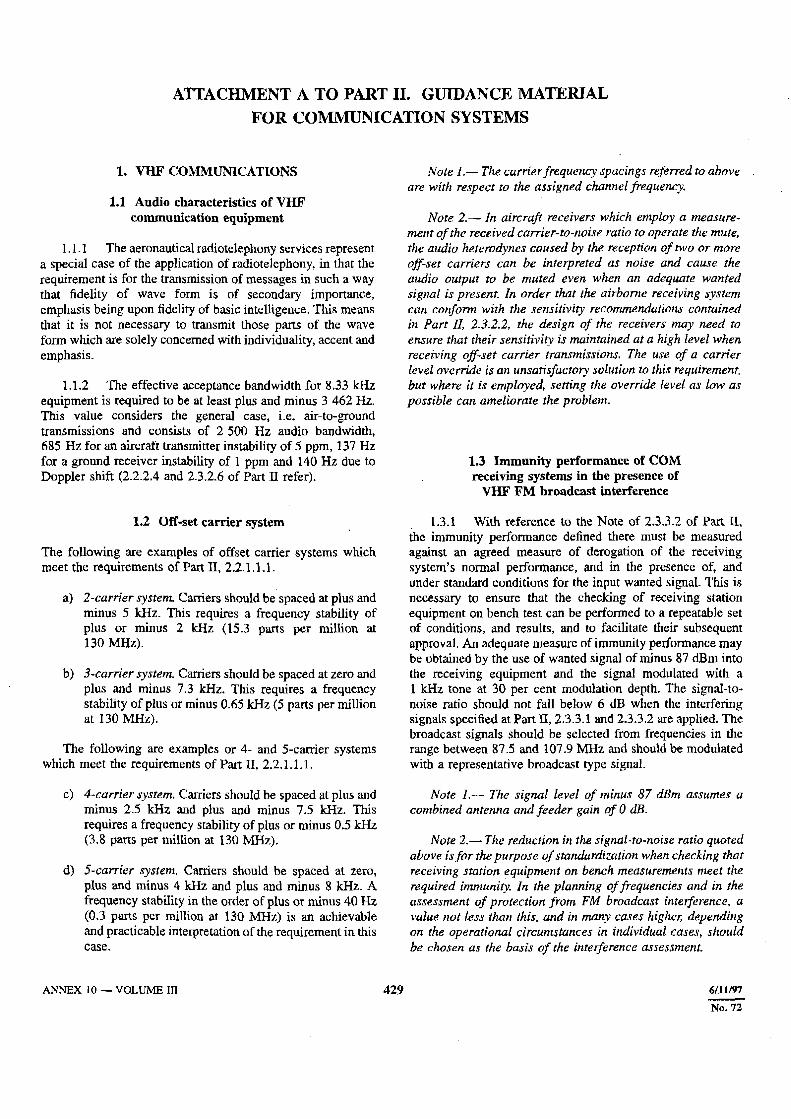
Attachment A to Part II — Guidance material for communication systems . . . . . . . . . . . . . . . . . . . . . . . . . 429
1. VHF communications . . . . . . . . . . . . . . . . . . . 4292. SELCAL system . . . . . . . . . . . . . . . . . . . . . . . 430

ANNEX 10 — VOLUME III (vii) 5/11/95
FOREWORD
Historical background
Standards and Recommended Practices for Aeronautical Tele-communications were first adopted by the Council on 30 May1949 pursuant to the provisions of Article 37 of the Conventionon International Civil Aviation (Chicago 1944) and designatedas Annex 10 to the Convention. They became effective on1 March 1950. The Standards and Recommended Practices werebased on recommendations of the Communications Division atits Third Session in January 1949.
Up to and including the Seventh Edition, Annex 10 waspublished in one volume containing four Parts together withassociated attachments: Part I — Equipment and Systems, PartII — Radio Frequencies, Part III — Procedures, and Part IV —Codes and Abbreviations.
By Amendment 42, Part IV was deleted from the Annex;the codes and abbreviations contained in that Part weretransferred to a new document, Doc 8400.
As a result of the adoption of Amendment 44 on 31 May1965, the Seventh Edition of Annex 10 was replaced by twovolumes: Volume I (First Edition) containing Part I —Equipment and Systems, and Part II — Radio Frequencies, andVolume II (First Edition) containing CommunicationProcedures.
As a result of the adoption of Amendment 70 on 20 March1995, Annex 10 was restructured to include five volumes:Volume I — Radio Navigation Aids; Volume II —Communication Procedures; Volume III — CommunicationSystems; Volume IV — Surveillance Radar and CollisionAvoidance Systems; and Volume V — Aeronautical RadioFrequency Spectrum Utilization. By Amendment 70, VolumesIII and IV were published in 1995 and Volume V was plannedfor publication with Amendment 71.
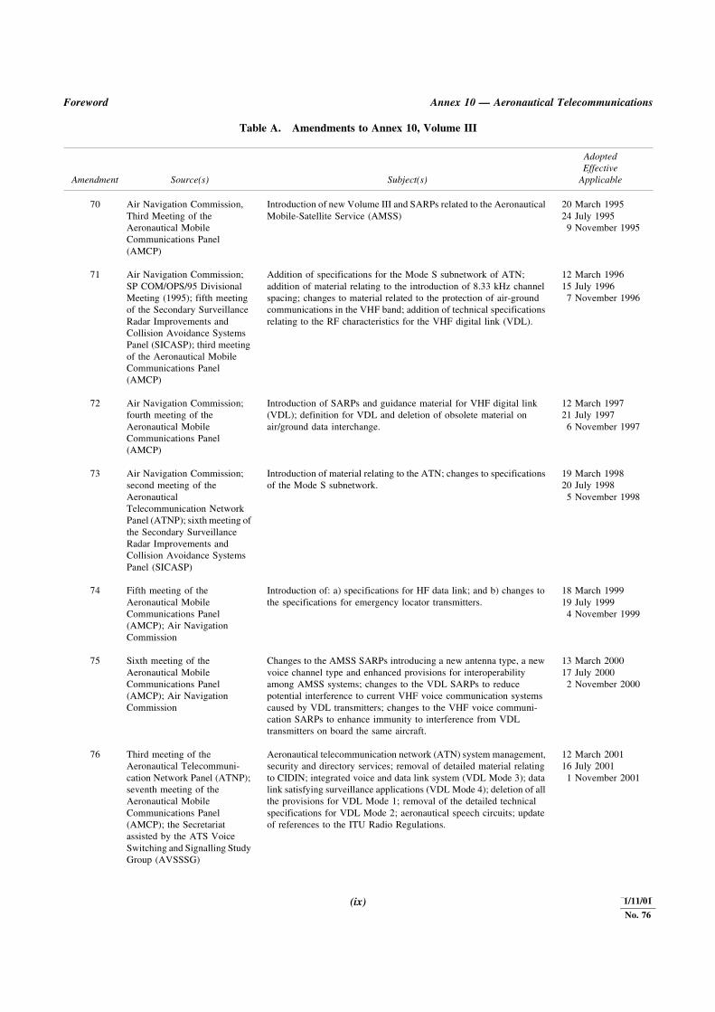
Table A shows the origin of Annex 10, Volume IIIsubsequent to Amendment 70, together with a summary of theprincipal subjects involved and the dates on which the Annexand the amendments were adopted by Council, when theybecame effective and when they became applicable.
Action by Contracting States
Notification of differences. The attention of Contracting Statesis drawn to the obligation imposed by Article 38 of theConvention by which Contracting States are required to notifythe Organization of any differences between their national
regulations and practices and the International Standardscontained in this Annex and any amendments thereto.Contracting States are invited to extend such notification toany differences from the Recommended Practices contained inthis Annex and any amendments thereto, when the notificationof such differences is important for the safety of air navigation.Further, Contracting States are invited to keep the Organizationcurrently informed of any differences which may subsequentlyoccur, or of the withdrawal of any differences previouslynotified. A specific request for notification of differences willbe sent to Contracting States immediately after the adoption ofeach amendment to this Annex.
The attention of States is also drawn to the provisions ofAnnex 15 related to the publication of differences betweentheir national regulations and practices and the related ICAOStandards and Recommended Practices through the Aero-nautical Information Service, in addition to the obligation ofStates under Article 38 of the Convention.
Promulgation of information. The establishment and with-drawal of and changes to facilities, services and proceduresaffecting aircraft operations provided in accordance with theStandards, Recommended Practices and Procedures specifiedin Annex 10 should be notified and take effect in accordancewith the provisions of Annex 15.
Use of the text of the Annex in national regulations. TheCouncil, on 13 April 1948, adopted a resolution inviting theattention of Contracting States to the desirability of using intheir own national regulations, as far as practicable, the preciselanguage of those ICAO Standards that are of a regulatorycharacter and also of indicating departures from the Standards,including any additional national regulations that were import-ant for the safety or regularity of air navigation. Whereverpossible, the provisions of this Annex have been deliberatelywritten in such a way as would facilitate incorporation,without major textual changes, into national legislation.
Status of Annex components
An Annex is made up of the following component parts, not allof which, however, are necessarily found in every Annex; theyhave the status indicated:
1.— Material comprising the Annex proper:
a) Standards and Recommended Practices adopted bythe Council under the provisions of the Convention.They are defined as follows:
7/11/96
No. 71

Annex 10 — Aeronautical Telecommunications Volume III
5/11/95 (viii)
Standard: Any specification for physicalcharacteristics, configuration, matériel, performance,personnel or procedure, the uniform application ofwhich is recognized as necessary for the safety orregularity of international air navigation and to whichContracting States will conform in accordance withthe Convention; in the event of impossibility ofcompliance, notification to the Council iscompulsory under Article 38.
Recommended Practice: Any specification forphysical characteristics, configuration, matériel,performance, personnel or procedure, the uniformapplication of which is recognized as desirable in theinterest of safety, regularity or efficiency ofinternational air navigation, and to which ContractingStates will endeavour to conform in accordance withthe Convention.
b) Appendices comprising material grouped separatelyfor convenience but forming part of the Standardsand Recommended Practices adopted by the Council.
c) Definitions of terms used in the Standards andRecommended Practices which are not self-explanatory in that they do not have accepteddictionary meanings. A definition does not haveindependent status but is an essential part of eachStandard and Recommended Practice in which theterm is used, since a change in the meaning of theterm would affect the specification.
d) Tables and Figures which add to or illustrate aStandard or Recommended Practice and which arereferred to therein, form part of the associatedStandard or Recommended Practice and have thesame status.
2.— Material approved by the Council for publication inassociation with the Standards and Recommended Practices:
a) Forewords comprising historical and explanatorymaterial based on the action of the Council andincluding an explanation of the obligations of Stateswith regard to the application of the Standards andRecommended Practices ensuing from theConvention and the Resolution of Adoption;
b) Introductions comprising explanatory materialintroduced at the beginning of parts, chapters orsections of the Annex to assist in the understandingof the application of the text;
c) Notes included in the text, where appropriate, to givefactual information or references bearing on theStandards or Recommended Practices in question,but not constituting part of the Standards orRecommended Practices;
d) Attachments comprising material supplementary tothe Standards and Recommended Practices, orincluded as a guide to their application.
Disclaimer regarding patents
Attention is drawn to the possibility that certain elements ofStandards and Recommended Practices in this Annex may bethe subject of patents or other intellectual property rights.ICAO shall not be responsible or liable for not identifying anyor all such rights. ICAO takes no position regarding theexistence, validity, scope or applicability of any claimedpatents or other intellectual property rights, and accepts noresponsibility or liability therefore or relating thereto.
Selection of language
This Annex has been adopted in four languages — English,French, Russian and Spanish. Each Contracting State isrequested to select one of those texts for the purpose ofnational implementation and for other effects provided for inthe Convention, either through direct use or through translationinto its own national language, and to notify the Organizationaccordingly.
Editorial practices
The following practice has been adhered to in order to indicateat a glance the status of each statement: Standards have beenprinted in light face roman; Recommended Practices have beenprinted in light face italics, the status being indicated by theprefix Recommendation; Notes have been printed in light faceitalics, the status being indicated by the prefix Note.
The following editorial practice has been followed in thewriting of specifications: for Standards the operative verb“shall” is used, and for Recommended Practices the operativeverb “should” is used.
The units of measurement used in this document are inaccordance with the International System of Units (SI) asspecified in Annex 5 to the Convention on International CivilAviation. Where Annex 5 permits the use of non-SI alternativeunits these are shown in parentheses following the basic units.Where two sets of units are quoted it must not be assumed thatthe pairs of values are equal and interchangeable. It may,however, be inferred that an equivalent level of safety isachieved when either set of units is used exclusively.
Any reference to a portion of this document, which isidentified by a number and/or title, includes all subdivisions ofthat portion.
28/11/02
No. 77
Foreword Annex 10 — Aeronautical Telecommunications
(ix) 5/11/95
Table A. Amendments to Annex 10, Volume III
Amendment Source(s) Subject(s)
AdoptedEffective
Applicable
70 Air Navigation Commission, Third Meeting of the Aeronautical Mobile Communications Panel (AMCP)
Introduction of new Volume III and SARPs related to the Aeronautical Mobile-Satellite Service (AMSS)
20 March 199524 July 19959 November 1995
71 Air Navigation Commission; SP COM/OPS/95 Divisional Meeting (1995); fifth meeting of the Secondary Surveillance Radar Improvements and Collision Avoidance Systems Panel (SICASP); third meeting of the Aeronautical Mobile Communications Panel (AMCP)
Addition of specifications for the Mode S subnetwork of ATN; addition of material relating to the introduction of 8.33 kHz channel spacing; changes to material related to the protection of air-ground communications in the VHF band; addition of technical specifications relating to the RF characteristics for the VHF digital link (VDL).
12 March 199615 July 19967 November 1996
72 Air Navigation Commission; fourth meeting of the Aeronautical Mobile Communications Panel (AMCP)
Introduction of SARPs and guidance material for VHF digital link (VDL); definition for VDL and deletion of obsolete material on air/ground data interchange.
12 March 199721 July 19976 November 1997
73 Air Navigation Commission; second meeting of the Aeronautical Telecommunication Network Panel (ATNP); sixth meeting of the Secondary Surveillance Radar Improvements and Collision Avoidance Systems Panel (SICASP)
Introduction of material relating to the ATN; changes to specifications of the Mode S subnetwork.
19 March 199820 July 19985 November 1998
74 Fifth meeting of the Aeronautical Mobile Communications Panel (AMCP); Air Navigation Commission
Introduction of: a) specifications for HF data link; and b) changes to the specifications for emergency locator transmitters.
18 March 199919 July 19994 November 1999
75 Sixth meeting of the Aeronautical Mobile Communications Panel (AMCP); Air Navigation Commission
Changes to the AMSS SARPs introducing a new antenna type, a new voice channel type and enhanced provisions for interoperability among AMSS systems; changes to the VDL SARPs to reduce potential interference to current VHF voice communication systems caused by VDL transmitters; changes to the VHF voice communi- cation SARPs to enhance immunity to interference from VDL transmitters on board the same aircraft.
13 March 200017 July 20002 November 2000
76 Third meeting of the Aeronautical Telecommuni-cation Network Panel (ATNP); seventh meeting of the Aeronautical Mobile Communications Panel (AMCP); the Secretariat assisted by the ATS Voice Switching and Signalling Study Group (AVSSSG)
Aeronautical telecommunication network (ATN) system management, security and directory services; removal of detailed material relating to CIDIN; integrated voice and data link system (VDL Mode 3); data link satisfying surveillance applications (VDL Mode 4); deletion of all the provisions for VDL Mode 1; removal of the detailed technical specifications for VDL Mode 2; aeronautical speech circuits; update of references to the ITU Radio Regulations.
12 March 200116 July 20011 November 2001
1/11/01
No. 76

��������������� �������������� ��������� ��� ������
������� ���
�� ��������� �������������������������������������������������������������������
�������� �������������� ���!���������"��������������# $��%�� ��$&&$'(�) ���$&&$$*�+�������$&&$
�* ���+��"��������������� �,�"���������,����������!�������������"��������!�- ������,�����.������ �������!��"���������- �������!��/01�.��������������!�230�������4����5�����,��������!��1+�� ������������������1����464�.������������������#
(���,�$&&4'5�) ���$&&4$��+�������$&&4
�7 /�",�,�������"��!��,������ ���������������� ��������������������
�,�"���������,����������!�������������"����,�",�!�- ��������������8%30�������"���,������,�������������������!��19���.������ �������!�%����� ������,����������!��230������5.�����������!��,���������������"��,��230������5���������������� �������������������#
$4�%�� ��$&&5'$�) ���$&&5$(�+�������$&&5
*& ���+��"��������������� ����������!���,�������������������!�� ���������"����������������������/01���������"�����,��5&: �8;�!�- ����#
$(�%�� ��$&&(''�) ���$&&($5�+�������$&&(
��������� ���� �� ������ ��
���������������
����������
��������
�� �


ANNEX 10 — VOLUME III 349 5/11/95
CHAPTER 4. AERONAUTICAL SPEECH CIRCUITS
4.1 TECHNICAL PROVISIONS RELATING
TO INTERNATIONAL AERONAUTICAL SPEECH
CIRCUIT SWITCHING AND SIGNALLING FOR
GROUND-GROUND APPLICATIONS
Note.— Guidance material on the implementation ofaeronautical speech circuit switching and signalling forground-ground applications is contained in the Manual on Air
Traffic Services (ATS) Ground-Ground Voice Switching and
Signalling (Doc 9804). The material includes explanation ofterms, perfor-mance parameters, guidance on basic call typesand additional functions, references to appropriate ISO/IECinternational standards and ITU-T recommendations,guidance on the use of signalling systems, details of therecommended numbering scheme and guidance on migrationto future schemes.
4.1.1 The use of circuit switching and signalling to
provide speech circuits to interconnect ATS units not
interconnected by dedicated circuits shall be by agreement
between the Administrations concerned.
4.1.2 The application of aeronautical speech circuit
switching and signalling shall be made on the basis of regional
air navigation agreements.
4.1.3 Recommendation.— The ATC communicationrequirements defined in Annex 11, Section 6.2 should be metby implementation of one or more of the following basic threecall types:
a) instantaneous access;
b) direct access; and
c) indirect access.
4.1.4 Recommendation.— In addition to the ability tomake basic telephone calls, the following functions should beprovided in order to meet the requirements set out in Annex 11:
a) means of indicating the calling/called party identity;
b) means of initiating urgent/priority calls; and
c) conference capabilities.
4.1.5 Recommendation.— The characteristics of thecircuits used in aeronautical speech circuit switching andsignalling should conform to appropriate ISO/IEC inter-national standards and ITU-T recommendations.
4.1.6 Recommendation.— Digital signalling systemsshould be used wherever their use can be justified in terms ofany of the following:
a) improved quality of service;
b) improved user facilities; or
c) reduced costs where quality of service is maintained.
4.1.7 Recommendation.— The characteristics ofsupervisory tones to be used (such as ringing, busy, numberunobtainable) should conform to appropriate ITU-Trecommendations.
4.1.8 Recommendation.— To take advantage of thebenefits of interconnecting regional and national aeronauticalspeech networks, the international aeronautical telephonenetwork numbering scheme should be used.
27/11/03
No. 78
5/11/95 350 ANNEX 10 — VOLUME III
CHAPTER 5. EMERGENCY LOCATOR TRANSMITTER (ELT)
FOR SEARCH AND RESCUE
5.1 GENERAL
5.1.1 Until 1 January 2005, emergency locator transmitters
shall operate either on both 406 MHz and 121.5 MHz or on
121.5 MHz.
Note.— From 1 January 2000, ELTs operating on121.5 MHz will be required to meet the improved technicalcharacteristics contained in 5.2.1.8.
5.1.2 All installations of emergency locator transmitters
operating on 406 MHz shall meet the provisions of 5.3.
5.1.3 All installations of emergency locator transmitters
operating on 121.5 MHz shall meet the provisions of 5.2.
5.1.4 From 1 January 2005, emergency locator
transmitters shall operate on 406 MHz and 121.5 MHz
simultaneously.
5.1.5 All emergency locator transmitters installed on or
after 1 January 2002 shall operate simultaneously on 406 MHz
and 121.5 MHz.
5.1.6 The technical characteristics for the 406 MHz
component of an integrated ELT shall be in accordance
with 5.3.
5.1.7 The technical characteristics for the 121.5 MHz
component of an integrated ELT shall be in accordance
with 5.2.
5.1.8 States shall make arrangements for a 406 MHz
ELT register. Register information regarding the ELT shall
be immediately available to search and rescue authorities.
States shall ensure that the register is updated whenever
necessary.
5.1.9 ELT register information shall include the
following:
a) transmitter identification (expressed in the form of an
alphanumerical code of 15 hexadecimal characters);
b) transmitter manufacturer, model and, when available,
manufacturer’s serial number;
c) COSPAS-SARSAT* type approval number;
d) name, address (postal and e-mail) and emergency
telephone number of the owner and operator;
e) name, address (postal and e-mail) and telephone number
of other emergency contacts (two, if possible) to whom
the owner or the operator is known;
f) aircraft manufacturer and type; and
g) colour of the aircraft.
Note 1.— Various coding protocols are available to States.Depending on the protocol adopted, States may, at theirdiscretion, include one of the following as supplementaryidentification information to be registered:
a) aircraft operating agency designator and operator’sserial number; or
b) 24-bit aircraft address; or
c) aircraft nationality and registration marks.
The aircraft operating agency designator is allocated to theoperator by ICAO through the State administration, and theoperator’s serial number is allocated by the operator from theblock 0001 to 4096.
Note 2.— At their discretion, depending on arrangements inplace, States may include other relevant information to beregistered such as the last date of register, battery expiry dateand place of ELT in the aircraft (e.g. “primary ELT” or“life-raft No. 1”).
5.2 SPECIFICATION FOR THE 121.5 MHZ
COMPONENT OF EMERGENCY
LOCATOR TRANSMITTER (ELT)
FOR SEARCH AND RESCUE
Note 1.— Information on technical characteristics andoperational performance of 121.5 MHz ELTs is contained inRTCA Document DO-183 and European Organization forCivil Aviation Equipment (EUROCAE) Document ED.62.
* COSPAS = Space system for search of vessels in distress;
SARSAT = Search and rescue satellite-aided tracking.
27/11/03
No. 78

Part II Annex 10 — Aeronautical Telecommunications
351 5/11/95
Note 2.— Technical characteristics of emergency locatortransmitters operating on 121.5 MHz are contained in ITU-RRecommendation M.690-1. The ITU designation for an ELT isEmergency Position — Indicating Radio Beacon (EPIRB).
5.2.1 Technical characteristics
5.2.1.1 Emergency locator transmitters (ELT) shall
operate on 121.5 MHz. The frequency tolerance shall not
exceed plus or minus 0.005 per cent.
5.2.1.2 The emission from an ELT under normal
conditions and attitudes of the antenna shall be vertically
polarized and essentially omnidirectional in the horizontal
plane.
5.2.1.3 Over a period of 48 hours of continuous operation,
at an operating temperature of minus 20°C, the peak effective
radiated power (PERP) shall at no time be less than 50 mW.
5.2.1.4 The type of emission shall be A3X. Any other
type of modulation that meets the requirements of 5.2.1.5,
5.2.1.6 and 5.2.1.7 below may be used provided that it will not
prejudice precise location of the beacon by homing equipment.
Note.— Some ELTs are equipped with an optional voicecapability (A3E) in addition to the A3X emission.
5.2.1.5 The carrier shall be amplitude modulated at a
modulation factor of at least 0.85.
5.2.1.6 The modulation applied to the carrier shall have a
minimum duty cycle of 33 per cent.
5.2.1.7 The emission shall have a distinctive audio
characteristic achieved by amplitude modulating the carrier
with an audio frequency sweeping downward over a range of
not less than 700 Hz within the range 1 600 Hz to 300 Hz and
with a sweep repetition rate of between 2 Hz and 4 Hz.
5.2.1.8 After 1 January 2000, the emission shall include a
clearly defined carrier frequency distinct from the modulation
sideband components; in particular, at least 30 per cent of the
power shall be contained at all times within plus or minus
30 Hz of the carrier frequency on 121.5 MHz.
5.3 SPECIFICATION FOR THE 406 MHZ
COMPONENT OF EMERGENCY
LOCATOR TRANSMITTER (ELT)
FOR SEARCH AND RESCUE
5.3.1 Technical characteristics
Note 1.— Transmission characteristics for 406 MHzemergency locator transmitters are contained in ITU-R M.633.
Note 2.— Information on technical characteristics andoperational performance of 406 MHz ELTs is contained inRTCA Document DO-204 and European Organization forCivil Aviation Equipment (EUROCAE) Document ED-62.
5.3.1.1 Emergency locator transmitters shall operate on
one of the frequency channels assigned for use in the
frequency band 406.0 to 406.1 MHz.
Note.— The COSPAS-SARSAT 406 MHz channel assignmentplan is contained in COSPAS-SARSAT Document C/S T.012.
5.3.1.2 The period between transmissions shall be
50 seconds plus or minus 5 per cent.
5.3.1.3 Over a period of 24 hours of continuous operation
at an operating temperature of –20°C, the transmitter power
output shall be within the limits of 5 W plus or minus 2 dB.
5.3.1.4 The 406 MHz ELT shall be capable of trans-
mitting a digital message.
5.3.2 Transmitter
identification coding
5.3.2.1 Emergency locator transmitters operating on
406 MHz shall be assigned a unique coding for identification
of the transmitter or aircraft on which it is carried.
5.3.2.2 The emergency locator transmitter shall be
coded in accordance with either the aviation user protocol or
one of the serialized user protocols described in Appendix 1
to this chapter, and shall be registered with the appropriate
authority.
27/11/03
No. 78

ANNEX 10 — VOLUME III 353 24/11/05
No. 80
APPENDIX 1 TO CHAPTER 5. EMERGENCY LOCATORTRANSMITTER CODING
(see Chapter 5, 5.3.2)
Note.— A detailed description of beacon coding iscontained in Specification for COSPAS-SARSAT 406 MHzDistress Beacons (C/S T.001). The following technical specifi-cations are specific to emergency locator transmitters used inaviation.
1. GENERAL
1.1 The emergency locator transmitter (ELT) operatingon 406 MHz shall have the capacity to transmit a programmeddigital message which contains information related to the ELTand/or the aircraft on which it is carried.
1.2 The ELT shall be uniquely coded in accordance with1.3 below and be registered with the appropriate authority.
1.3 The ELT digital message shall contain either thetransmitter serial number or one of the following informationelements:
a) aircraft operating agency designator and a serial number;
b) 24-bit aircraft address;
c) aircraft nationality and registration marks.
1.4 All ELTs shall be designed for operation with theCOSPAS-SARSAT* system and be type approved.
Note.— Transmission characteristics of the ELT signal canbe confirmed by making use of the COSPAS-SARSAT TypeApproval Standard (C/S T.007).
2. ELT CODING
2.1 The ELT digital message shall contain informationrelating to the message format, coding protocol, country code,identification data and location data, as appropriate.
2.2 For ELTs with no navigation data provided, the shortmessage format C/S T.001 shall be used, making use of bits1 through 112. For ELTs with navigation data, if provided, thelong message format shall be used, making use of bits1 through 144.
2.3 Protected data field
2.3.1 The protected data field consisting of bits 25through 85 shall be protected by an error correcting code, andshall be the portion of the message which shall be unique inevery distress ELT.
2.3.2 A message format flag indicated by bit 25 shall beset to “0” to indicate the short message format or set to “1” toindicate the long format for ELTs capable of providinglocation data.
2.3.3 A protocol flag shall be indicated by bit 26 and shallbe set to “1” for user and user location protocols, and “0” forlocation protocols.
2.3.4 A country code, which indicates the State whereadditional data are available on the aircraft on which the ELTis carried, shall be contained in bits 27 through 36 whichdesignate a three-digit decimal country code number expressedin binary notation.
Note.— Country codes are based on the InternationalTelecommunication Union (ITU) country codes shown inTable 4 of Part I, Volume I of the ITU List of Call Signs andNumerical Identities.
2.3.5 Bits 37 through 39 (user and user location proto-cols) or bits 37 through 40 (location protocols) shall designateone of the protocols where values “001” and “011” or “0011”,“0100”, “0101”, and “1000” are used for aviation as shown inthe examples contained in this Appendix.
2.3.6 The ELT digital message shall contain either thetransmitter serial number or an identification of the aircraft oroperator as shown below.
2.3.7 In the serial user and serial user location protocol(designated by bit 26=1 and bits 37 through 39 being “011”),the serial identification data shall be encoded in binary nota-tion with the least significant bit on the right. Bits 40 through42 shall indicate type of ELT serial identification data encodedwhere:
— “000” indicates ELT serial number (binary notation) isencoded in bits 44 through 63;
— “001” indicates aircraft operator (3 letter encoded usingmodified Baudot code shown in Table 5-1) and a serialnumber (binary notation) are encoded in bits 44 through61 and 62 through 73, respectively;
* COSPAS = Space system for search of vessels in distress;SARSAT = Search and rescue satellite-aided tracking.
Annex 10 — Aeronautical Telecommunications Volume III
35424/11/05
No. 80
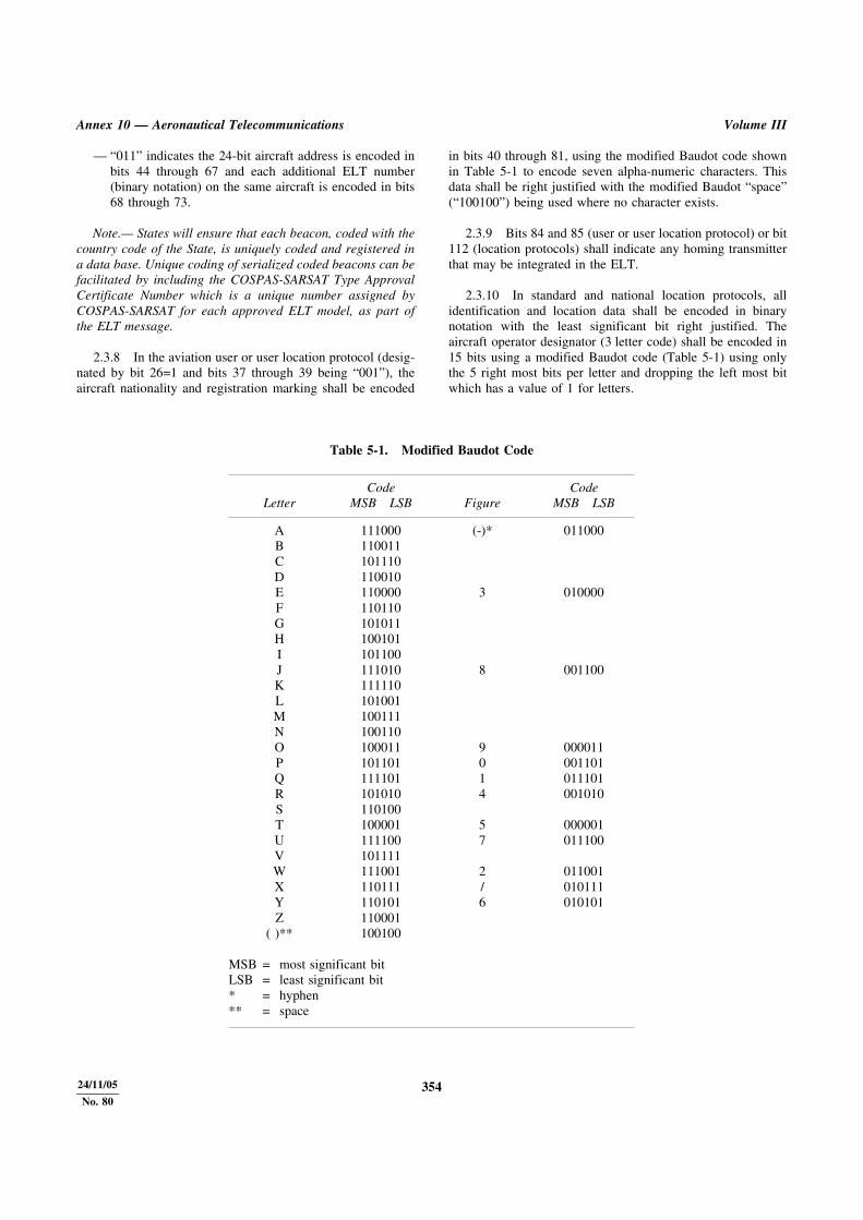
— “011” indicates the 24-bit aircraft address is encoded inbits 44 through 67 and each additional ELT number(binary notation) on the same aircraft is encoded in bits68 through 73.
Note.— States will ensure that each beacon, coded with thecountry code of the State, is uniquely coded and registered ina data base. Unique coding of serialized coded beacons can befacilitated by including the COSPAS-SARSAT Type ApprovalCertificate Number which is a unique number assigned byCOSPAS-SARSAT for each approved ELT model, as part ofthe ELT message.
2.3.8 In the aviation user or user location protocol (desig-nated by bit 26=1 and bits 37 through 39 being “001”), theaircraft nationality and registration marking shall be encoded
in bits 40 through 81, using the modified Baudot code shownin Table 5-1 to encode seven alpha-numeric characters. Thisdata shall be right justified with the modified Baudot “space”(“100100”) being used where no character exists.
2.3.9 Bits 84 and 85 (user or user location protocol) or bit112 (location protocols) shall indicate any homing transmitterthat may be integrated in the ELT.
2.3.10 In standard and national location protocols, allidentification and location data shall be encoded in binarynotation with the least significant bit right justified. Theaircraft operator designator (3 letter code) shall be encoded in15 bits using a modified Baudot code (Table 5-1) using onlythe 5 right most bits per letter and dropping the left most bitwhich has a value of 1 for letters.
Table 5-1. Modified Baudot Code
LetterCode
MSB LSB FigureCode
MSB LSB
A 111000 (-)* 011000B 110011C 101110D 110010E 110000 3 010000F 110110G 101011H 100101I 101100J 111010 8 001100K 111110L 101001M 100111N 100110O 100011 9 000011P 101101 0 001101Q 111101 1 011101R 101010 4 001010S 110100T 100001 5 000001U 111100 7 011100V 101111W 111001 2 011001X 110111 / 010111Y 110101 6 010101Z 110001
( )** 100100
MSB = most significant bitLSB = least significant bit* = hyphen** = space

Part II Annex 10 — Aeronautical Telecommunications
355 24/11/05
No. 80
EXAMPLES OF CODING
ELT serial number
Aircraft address
Aircraft operator designator and serial number
Aircraft registration marking
Note 1.— 10 bits, all 0s or National use.
Note 2.— COSPAS-SARSAT Type Approval Certificate number in binary notation with the least significant bit on the right, orNational use.
Note 3.— Serial number, in binary notation with the least significant bit on the right, of additional ELTs carried in the sameaircraft or default to 0s when only one ELT is carried.
25 27 36 37 40 44 63 64 73 74 83 85
F 1 COUNTRY 0 1 1 T T T CSERIAL NUMBER DATA
(20 BITS)SEE NOTE 1 SEE NOTE 2 A A
25 27 36 37 40 44 67 68 73 74 83 85
F 1 COUNTRY 0 1 1 T T T CAIRCRAFT ADDRESS
(24 BITS)SEE NOTE 3 SEE NOTE 2 A A
25 27 36 37 40 44 61 62 73 74 83 85
F 1 COUNTRY 0 1 1 T T T COPERATOR 3-LETTER
DESIGNATOR
SERIALNUMBER
1-4096SEE NOTE 2 A A
25 27 36 37 40 81 83 85
F 1 COUNTRY 0 0 1AIRCRAFT REGISTRATION MARKING (UP TO7 ALPHANUMERIC CHARACTERS) (42 BITS)
0 0 A A
T = Beacon type TTT = 000 indicates ELT serial number is encoded;= 001 indicates operating agency and serial number are encoded;= 011 indicates 24-bit aircraft address is encoded.
C = Certificate flag bit: 1 = to indicate that COSPAS-SARSAT Type Approval Certificate number is encoded in bits 74through 83 and
0 = otherwise
F = Format flag: 0 = Short Message1 = Long Message
A = Auxiliary radio-locating device: 00 = no auxiliary radio-locating device01 = 121.5 MHz11 = other auxiliary radio-locating device
Annex 10 — Aeronautical Telecommunications Volume III
35624/11/05
No. 80
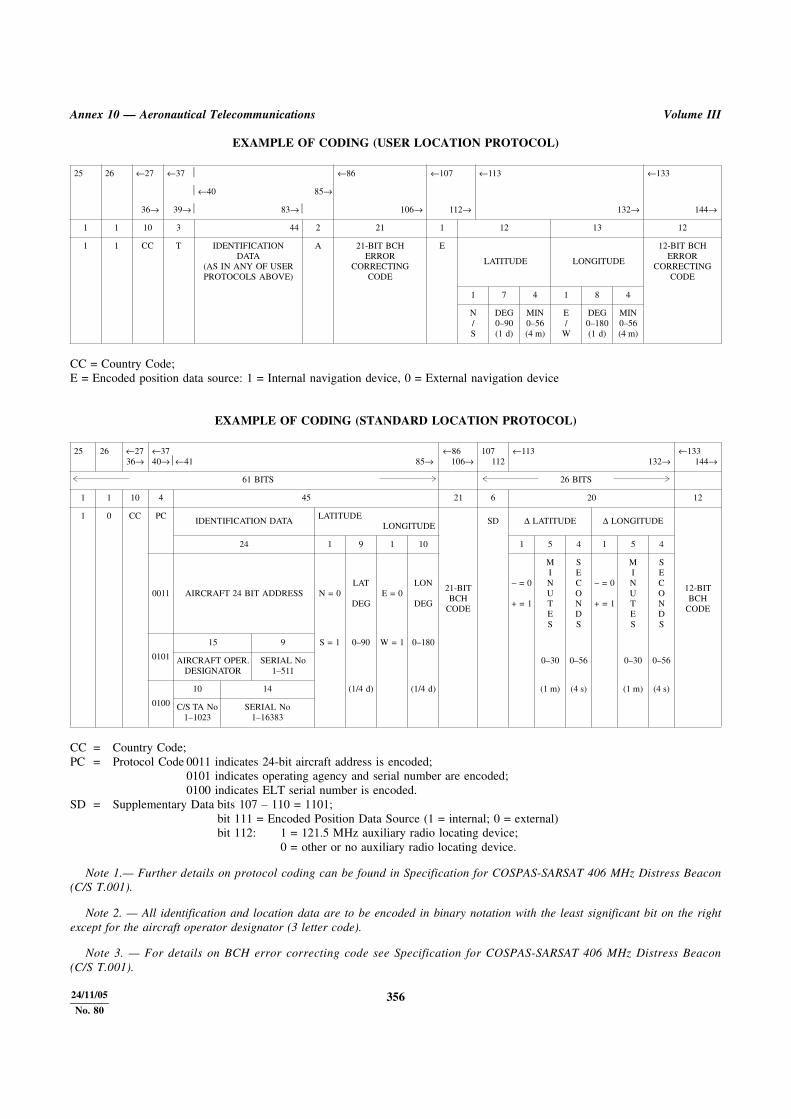
EXAMPLE OF CODING (USER LOCATION PROTOCOL)
CC = Country Code;E = Encoded position data source: 1 = Internal navigation device, 0 = External navigation device
EXAMPLE OF CODING (STANDARD LOCATION PROTOCOL)
CC = Country Code;PC = Protocol Code 0011 indicates 24-bit aircraft address is encoded;
0101 indicates operating agency and serial number are encoded;0100 indicates ELT serial number is encoded.
SD = Supplementary Data bits 107 – 110 = 1101;bit 111 = Encoded Position Data Source (1 = internal; 0 = external)bit 112: 1 = 121.5 MHz auxiliary radio locating device;
0 = other or no auxiliary radio locating device.
Note 1.— Further details on protocol coding can be found in Specification for COSPAS-SARSAT 406 MHz Distress Beacon(C/S T.001).
Note 2. — All identification and location data are to be encoded in binary notation with the least significant bit on the rightexcept for the aircraft operator designator (3 letter code).
Note 3. — For details on BCH error correcting code see Specification for COSPAS-SARSAT 406 MHz Distress Beacon(C/S T.001).
25 26 ←27 ←37 ⏐ ←86 ←107 ←113 ←133
⏐ ←40 85→
36→ 39→⏐ 83→⏐ 106→ 112→ 132→ 144→
1 1 10 3 44 2 21 1 12 13 12
1 1 CC T IDENTIFICATIONDATA
(AS IN ANY OF USERPROTOCOLS ABOVE)
A 21-BIT BCHERROR
CORRECTINGCODE
E
LATITUDE LONGITUDE
12-BIT BCHERROR
CORRECTINGCODE
1 7 4 1 8 4
N/S
DEG0–90(1 d)
MIN0–56(4 m)
E/
W
DEG0–180(1 d)
MIN0–56(4 m)
25 26 ←2736→
←3740→⏐←41 85→
←86106→
107112
←113132→
←133144→
61 BITS 26 BITS
1 1 10 4 45 21 6 20 12
1 0 CC PCIDENTIFICATION DATA
LATITUDELONGITUDE
21-BITBCH
CODE
SD Δ LATITUDE Δ LONGITUDE
12-BITBCH
CODE
24 1 9 1 10 1 5 4 1 5 4
0011 AIRCRAFT 24 BIT ADDRESS N = 0LAT
DEGE = 0
LON
DEG
– = 0
+ = 1
MINUTES
SECONDS
– = 0
+ = 1
MINUTES
SECONDS
0101
15 9 S = 1 0–90 W = 1 0–180
AIRCRAFT OPER.DESIGNATOR
SERIAL No1–511
0–30 0–56 0–30 0–56
0100
10 14 (1/4 d) (1/4 d) (1 m) (4 s) (1 m) (4 s)
C/S TA No1–1023
SERIAL No1–16383

Part II Annex 10 — Aeronautical Telecommunications
357 24/11/05
No. 80
EXAMPLE OF CODING (NATIONAL LOCATION PROTOCOL)
CC = Country Code;ID = Identification Data = 8-bit identification data consisting of a serial number assigned by the appropriate national authoritySD = Supplementary Data = bits 107 – 109 = 110;
bit 110 = Additional Data Flag describing the use of bits 113 to 132:1 = Delta position; 0 = National assignment;bit 111 = Encoded Position Data Source: 1 = internal, 0 = external;bit 112: 1 = 121.5 MHz auxiliary radio locating device;
0 = other or no deviceNU = National use = 6 bits reserved for national use (additional beacon type identification or other uses).
Note 1.— Further details on protocol coding can be found in Specification for COSPAS-SARSAT 406 MHz Distress Beacon(C/S T.001).
Note 2.— All identification and location data are to be encoded in binary notation with the least significant bit on the right.
Note 3.— For details on BCH error correcting code see Specification for COSPAS-SARSAT 406 MHZ Distress Beacon(C/S T.001).
25 26 ←27
36→
←37
40→⏐←41 85→
←86
106→
107
112
←113
132→
←133
144→
61 BITSPDF-1
BCH-1 26 BITSPDF-2
BCH-2
1 1 10 4 45 21 6 7 7 6 12
1 0 CC 1000 18 bits
ID
27 bitsLATITUDE
LONGITUDE
21-BITBCH
CODE
SD Δ LATITUDE Δ LONGITUDE
12-BITBCH
CODE
18 1 7 5 1 8 5 1 2 4 1 2 4 NU
NATIONALID
NUMBER
N = 0
S = 1
DEGREES
0–90
(1 d)
MINUTES
0–58
(2 m)
E = 0
W = 1
DEGREES
0–180
(1 d)
MINUTES
0–58
(2 m)
– = 0
+ = 1
MINUTES
0–3
(1 m)
SECONDS
0–56
(4 s)
– = 0
+ = 1
MINUTES
0–3
(1 m)
SECONDS
0–56
(4 s)
356A