ankle spanning, knee spanning, long bone andpelvic · • freedom clamps provide the ability to...
TRANSCRIPT

Surgical Technique
Ankle Spanning, Knee Spanning, Long Bone and Pelvic


1
Nota Bene
The technique description herein is made available to the healthcare professional to illustrate the author’s suggested treatment for the uncomplicated procedure. In the final analysis, the preferred treatment is that which addresses the needs of the specific patient.
JET-X™ External Fixation SystemAnkle Spanning, Knee Spanning, Long Bone and Pelvic Surgical Technique
Contents
System Features .........................................................................2
Ankle Spanning Surgical Technique
Indications ...................................................................................4
Surgical Technique .....................................................................4
Knee Spanning Surgical Technique
Indications ...................................................................................8
Surgical Technique .....................................................................8
Long Bone Surgical Technique
Indications ................................................................................. 12
Surgical Technique ................................................................... 12
Pelvic Surgical Technique
Indications ................................................................................. 16
Surgical Technique ................................................................... 16
Catalog Information ................................................................ 18
Sterilization/Resterilization................................................... 36

2
System features
Indications
Intended to be used on adults or pediatric patients as required for fracture fixation (open or closed); post-traumatic joint contracture which has resulted in loss of range of motion; fractures and disease which generally may result in joint contractures or loss of range of motion and fractures requiring distraction; pseudoarthrosis of long bones; limb lengthening by epiphyseal or metaphyseal distraction; correction of bony or soft tissue deformity; correction of segmental bony or soft tissue defects; infected fractures or non-unions; joint arthrodesis; and management of comminuted intra-articular fracture of the distal radius.
Designed for flexibility in frame construction and ease of use
• Freedom Clamps provide the ability to angle pins up to 50º and also allow linear reduction of fractures with true translation of long bone fragment ends.
• Quick Clamps allow for rapid application, stability, and single point tightening
• Cartridge clamp design is positive locking – no passive release of pins or bars – even when clamps are loosened
• The system includes four hole and six hole multiple clamps to optimize pin spread
• The four hole and six hole clamps offer several attachment posts to maximize construct alternatives
• Various clamps and bar lengths give the surgeon the versatility to assemble the necessary frame constructs
• Self-drilling, self-tapping JET-X™ Half Pins
• Stainless steel pins with TiN* coating to reduce friction, which may minimize heat during insertion
• Tapered minor/constant major diameter of half pins provide radial compression to prevent loosening
• JET-X clamp components are designed to meet ASTM** MR Conditional requirements***
*TiN = Stainless Steel Half Pins with a Titanium Nitride coating **American Society for Testing and Materials***See IFU for specific MR Conditional information
Freedom Bar-to-Pin Clamp
Quick Bar-to-Bar Clamp
Quick Bar-to-Pin Clamp
Freedom Bar-to-Bar Clamp
Stainless steel pin with TiN coating
1
System features
IndicationsIntended to be used on adults or pediatric patients as required for fracture fixation (open or closed); post-traumatic joint contracture which has resulted inloss of range of motion; fractures and disease whichgenerally may result in joint contractures or loss ofrange of motion and fractures requiring distraction;pseudoarthrosis of long bones; limb lengthening byepiphyseal or metaphyseal distraction; correction ofbony or soft tissue deformity; correction of segmentalbony or soft tissue defects; infected fractures or non-unions; joint arthrodesis; and management ofcomminuted intra-articular fracture of the distal radius.
Designed for flexibility in frameconstruction and ease of use
• Freedom Clamps provide the ability to angle pins up to 50º and also allow linear reduction of fractures with true translation of long bone fragment ends.
• Quick Clamps allow for rapid application, stability, and single point tightening
• Cartridge clamp design is positive locking – no passive release of pins or bars – even when clampsare loosened
• The system includes four hole and six hole multipleclamps to optimize pin spread
• The four hole and six hole clamps offer several attachment posts to maximize construct alternatives
• Various clamps and bar lengths give the surgeon theversatility to assemble the necessary frame constructs
• Self-drilling, self-tapping JET-X™ Half Pins
• Stainless steel pins with TiN* coating to reduce friction, which may minimize heat during insertion
• Tapered minor/constant major diameter of half pinsprovide radial compression to prevent loosening
• JET-X clamp components are designed to meetASTM** MR Conditional requirements***
Freedom Bar-to-Pin Clamp
Freedom Bar-to-Bar Clamp
Quick Bar-to-Pin Clamp
Freedom Post 30º Post Straight Post
Stainless steel pin with TiN coating
Quick Bar-to-Bar Clamp
The multiple pinclamps are designedso that half pin spacing is compatiblewith Rancho cubes for definitive treatment
The four hole and six hole clamps offer several attachmentposts to maximize construct alternatives
*TiN = Stainless Steel Half Pins with a Titanium Nitride coating**American Society for Testing and Materials
***See IFU for specific MR Conditional information

3
Ankle Spanning Surgical Technique
4
JET-X™ External Fixator Ankle Spanning Surgical Technique
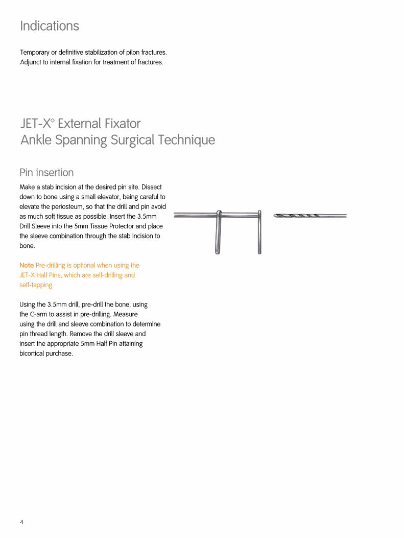
Pin insertionMake a stab incision at the desired pin site. Dissect down to bone using a small elevator, being careful to elevate the periosteum, so that the drill and pin avoid as much soft tissue as possible. Insert the 3.5mm Drill Sleeve into the 5mm Tissue Protector and place the sleeve combination through the stab incision to bone.
Note Pre-drilling is optional when using the JET-X Half Pins, which are self-drilling and self-tapping.
Using the 3.5mm drill, pre-drill the bone, using the C-arm to assist in pre-drilling. Measure using the drill and sleeve combination to determine pin thread length. Remove the drill sleeve and insert the appropriate 5mm Half Pin attaining bicortical purchase.
Indications
Temporary or definitive stabilization of pilon fractures. Adjunct to internal fixation for treatment of fractures.

5
Pin placement/ frame constructionThe working construct is a delta frame using a Multiple Pin Clamp.
Calcaneal pin placement
Place a centrally threaded half pin (traction pin) through the calcaneus in the safe zone from medial to lateral. Position this pin parallel to the ankle joint or perpendicular to the mechanical axis of the tibia. The pin should be positioned in the tuberosity, posterior to the sagittal axis line to produce a dorsiflexion moment with distraction. Confirm pin placement using the C-arm.
Note Construct shown utilizes the Quick Clamp. Freedom clamps may also be used for frame construction.
Tibial pin placement
Place the tibial pins in the AP plane. Direct AP oranteromedial are optimal placements. If treatment is to progress to ORIF, proximal half pins should be placed outside the planned area of fixation and zone of injury.
Use the Multiple Pin Clamp and Tissue Protectors to insert half pins and ensure proper spacing. Allow for planned future fixation and avoid zone of injury.
Select the appropriate posts and snap them into the Multiple Pin Clamp. Add a Pin to Bar Clamp to the calcaneal traction pin and attach carbon fiber bars. Reduce the fracture and tighten all clamps using the 10mm Ratchet Wrench or AO T-Handle Connector with 10mm Socket.
Note Construct shown with Freedom Post attachments. A Straight Post or 30º Angled Post could be used but would require an additional Bar to Bar Clamp.

6
Metatarsal pin placementAn additional metatarsal pin can be placed to incorporate the foot. Place the desired half pin size (3mm or 4mm) into the base of the first metatarsal at a slight angle into the anterior medial aspect. This is done to avoid tethering of the extensor tendons. Attach the pin to the bar using a Quick or Freedom Bar to Pin Clamp.
Note Construct shown utilizes the 10.5mm to 4mm Quick Clamp and 4mm TiN Half Pin.
Optional frame constructs
Construct shown utilizes the six hole Multiple Pin Clamp with 30º posts and the 10.5mm to 4mm Quick Clamp with a 4mm TiN pin in the first metatarsal
Construct shown utilizes the six hole Multiple Pin Clamp with straight posts and the 10.5mm to 4mm Quick Clamp with a 4mm TiN pin in the first metatarsal
Construct shown utilizes four 10.5mm Bar to 5mm Pin Clamps and the 10.5mm to 4mm Quick Clamp with a 4mm TiN pin in the first metatarsal

7
Knee Spanning Surgical Technique

8
JET-X™ External FixatorKnee Spanning Surgical Technique
Pin insertionMake a stab incision at the desired pin site. Dissect down to bone using a small elevator, being careful to elevate the periosteum, so that the drill and pin avoid as much soft tissue as possible. Insert the 3.5mm Drill Sleeve into the 5mm Tissue Protector and place the sleeve combination through the stab incision to bone.
Note Pre-drilling is optional when using the JET-X Half Pins, which are self-drilling and self-tapping.
Using the 3.5mm Drill, pre-drill the bone, using the C-arm to assist in pre-drilling. Measure using the drill and sleeve combination to determine pin thread length. Remove the drill sleeve and insert the appropriate 5mm Half Pin attaining bicortical purchase.
Indications
Temporary stabilization of fractures and severe soft tissue injuries, such as tibial plateau, supracondylar femur, extensor mechanism disruption and knee dislocation.

9
Pin placement/ frame constructionTibial pinsPlace initial half pin just distal to the zone of injury and distal to planned future fixation. The pin should be placed AP, just medial to the anterior tibial crest.
The second tibial pin should be inserted distally at the diaphyseal-metaphyseal junction to obtain maximum pin spread. Attach Quick or Freedom Bar to Pin Clamps to each tibial pin.
Choose a bar of appropriate length to end at the level of patella. Attach this bar to the Bar to Pin Clamps. This bar is placed approximately two finger breadths above skin level to allow for swelling of the soft tissue.
Femoral pins
(Frame option #1)
Insert two half pins straight anterior through the quadriceps. Use maximum pin spread for construct stability. Attach Quick or Freedom Bar to Pin Clamps to each pin.
Choose a bar that is long enough to cross the proximal end of the tibial bar. Attach this bar to the Bar to Pin Clamps. This bar should be placed approximately two finger breadths above skin level to allow for swelling of the soft tissue.
Connector barsAttach Quick or Freedom Bar to Bar Clamps to the tibial and femoral bars. Attach a third bar to these clamps. Distract the leg and reduce the fracture. Verify reduction by C-arm and tighten all clamps.
Note For additional stability, bars can be double stacked.

10
Optional frame constructs
Construct shown utilizes the six hole Multiple Pin Clamp with Straight Posts in the proximal anddistal portions.
Construct shown utilizes the six holeMultiple Pin Clamp with Freedom Posts in the proximal and distal portions.

11
Long Bone Surgical Technique

12
JET-X™ External Fixator Long Bone Surgical Technique
Pin insertionMake a stab incision at the desired pin site. Dissect down to bone using a small elevator, being careful to elevate the periosteum, so that the drill and pin avoid as much soft tissue as possible. Insert the 3.5mm Drill Sleeve into the 5mm Tissue Protector and place the sleeve combination through the stab incision to bone.
Note Pre-drilling is optional when using JET-X Half Pins, which are self-drilling and self-tapping.
Using the 3.5mm Drill, pre-drill the bone, using the C-arm to assist in pre-drilling. Measure using the drill and sleeve combination to determine pin thread length. Remove the drill sleeve and insert the appropriate 5mm Half Pin attaining bicortical purchase.
Indications
Treatment of long bone fractures. First stage stabilization of fractures that will be treated definitively with ORIF.
13
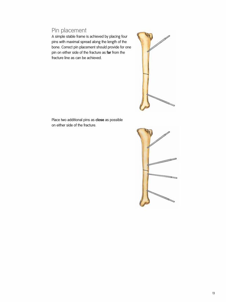
Pin placement A simple stable frame is achieved by placing four pins with maximal spread along the length of the bone. Correct pin placement should provide for one pin on either side of the fracture as far from the fracture line as can be achieved.
Place two additional pins as close as possibleon either side of the fracture.

14
Using Freedom Bar to Pin Clamps, snap the pin clamps onto the pins. Snap the appropriate length bar(s) into the bar clamps.
If fracture reduction is satisfactory, the wide adjustability of the clamps allows for one connecting bar to be snapped into all four Freedom Bar to Pin Clamps. Once tightened, the reduction is maintained.
If reduction is difficult to maintain, the proximal and distal pin couples can each be connected with separate short bars. Using both bars as reduction tools, the fracture can be manipulated to achieve reduction and stability. Freedom Bar to Bar Clamps are then attached to each short bar, and a long bar is then snapped into place to connect the proximal and distal fracture blocks.
After assembly of the needed frame, tighten the pin side of the Freedom Bar to Pin Clamps using a 10mm wrench. This will only lock the clamp to the pin, leaving the ball component free to move to aid in reduction. Reduce the fracture and tighten the bar side of the Bar to Pin Clamps and the Bar to Bar Clamps.

15
Pelvic Surgical Technique

16
JET-X™ External Fixator Pelvic Surgical Technique
Pin insertionMake a stab incision at the desired pin site. Dissect down to bone using a small elevator, being careful to elevate the periosteum, so that the drill and pin avoid as much soft tissue as possible. Insert the 3.5mm Drill Sleeve into the 5mm Tissue Protector and place the sleeve combination through the stab incision to bone.
Note Pre-drilling is optional when using JET-X Half Pins, which are self-drilling and self-tapping.
Using the 3.5 mm Drill, pre-drill the bone, using the C-arm to assist in pre-drilling. Measure using the drill and sleeve combination to determine pin thread length. Remove the drill sleeve and insert the appropriate 5mm Half Pin attaining bicortical purchase.
Indications
Closed fracture fixation such as unstable open book pelvic fractures, unstable anterior pelvic ring with bilateral rami fracture not amenable to internal fixation.

17
Pin placement/ frame constructionTwo half pins should be inserted on each side of the pelvis. One pin is inserted at each anterior inferior iliac spine under C-arm guidance directed obliquely toward the PSIS and/or greater sciatic notch (best available bone).
A second pin is inserted just cephalad to the ASIS on each side between the inner and outer tables. Using Freedom Bar to Pin Clamps, snap the pin clamps onto the four pins. Snap the appropriate length bar(s) into the Bar to Pin Clamps and secure the pin portion of the clamp using a 10mm wrench. Check for soft tissue clearance with leg flexed to 90°.
Apply a Bar to Bar Clamp by snapping the clamp onto each bar between fixation pins. Attach one bar of the appropriate length into the Bar to Bar Clamp on each side of the pelvis. These two bars should be connected by a Bar to Bar Clamp, anterior to the pelvis.
Align the bars depending on need for access to abdomen or need for sitting. The pelvis is manually compressed on each iliac wing until adequately reduced. Once the frame is positioned appropriately, tighten both sides of the Bar to Bar Clamps.
Using the Bar to Bar Clamps, add an additional cross bar or double stack as needed. Simply snap the bars into the cartridge mechanism of the clamp.
Optional frame constructConstruct shown utilizes two bars, one Bar to Bar Clamp, and two Bar to Pin Clamps.

18
JET-X™ BAR – External Fixation Devices
Description
7106-7372 10.5mm Bar to 5mm Pin
7106-7374 10.5mm Bar to 10.5mm Bar
7106-7373 10.5mm Bar to 6mm Pin
Quick Clamps – Aluminum and Stainless Steel on Tightening Bolts
4 Hole Pin ClampCat. No. 7106-7375
6 Hole Pin ClampCat. No. 7106-7376
Description
7106-4001 10.5mm Bar to 5mm Pin
7106-4002 10.5mm Bar to 10.5mm Bar
7106-4010 10.5mm Bar to 4mm Pin
7106-2722* 10.5mm Bar to Ring
7106-4019** 10.5mm Bar to 6mm Pin
Freedom Clamps – Aluminum, Titanium and Stainless Steel on Tightening Bolts
* In addition to other rings, also works with TAyLOR SPATIAL FRAME™ 2/3, Half and Full Rings ** Option accept both bar to pin and bar to bar
Catalog Information

19
JET-X™ BAR – External Fixation Devices
Bar CapsCat. No. 7106-2008
Description
7106-2100 100mm Bar
7106-2150 150mm Bar
7106-2160 L Bar
7106-2180 V Bar
7106-2200 200mm Bar
7106-2250 250mm Bar
7106-2300 300mm Bar
7106-2350 350mm Bar
7106-2400 400mm Bar
7106-2500 500mm Bar*
7106-2600 600mm Bar*
7106-4006 Add-A-Bar Coupler
Bars
100mm Bar
V BarL Bar
*Sterile packaged components
30º Angled Post Cat. No. 7106-7381
Freedom PostCat. No. 7106-7382
Straight PostCat. No. 7106-7379

20
Freedom Ankle Clamp Cat. No. 7106-2721
Distractor Clip, Package Quantity 2 Cat. No. 7106-3002
AO to Hall Adaptor*Cat. No. 7106-3004
10mm Ratchet WrenchCat. No. 7106-7322
Quick Clamp Bar to Pin Drill Guide Cat. No. 7106-7324
AO T-Handle Connector with 10mm Socket Cat. No. 7106-7326
JET-X BAR – Instruments
JET-X™ BAR – External Fixation Devices
*Will work with TRIGEN™ SURESHOT™ Hexdriver

21
5mm/6mm Tissue Protectorfor Long Half Pin Cat. No. 7106-7312
5mm/6mm Tissue Protectorfor Short Half Pin Cat. No. 7106-7313
5mm/6mm Long Trocar Cat. No. 7106-7306
5mm/6mm Short Trocar Cat. No. 7106-7307
5mm/6mm Extra Short TrocarCat. No. 7106-7308
Tissue Protector Handle Cat. No. 7106-7310
JET-X™ BAR – Instruments
Drill for Extra Short 5mm Half PinCat. No. 7106-7317
Drill for Short 5mm Half Pin Cat. No. 7106-7318
Drill for Long 5mm Half Pin Cat. No. 7106-7319
Drill for Short 6mm Half Pin Cat. No. 7106-7320
Drill for Long 6mm Half Pin Cat. No. 7106-7321
5mm/6mm Tissue Protectorfor Extra Short Half Pin Cat. No. 7106-7314

22
Add-A-Bar CouplerCat. No. 7106-2006
Original JET-X™ BAR – Instruments
AO T-Handle Connectorwith 10mm SocketCat. No. 7106-3001
5mm Bar to Pin Guide Cat. No. 7106-3010
6mm Bar to Pin Drill Guide Cat. No. 7106-3024
AO to Trinkle Adaptor Cat. No. 7106-3005

23
JET-X™ MINI – External Fixation Devices
Double Pin Clamp with Ball Joint Cat. No. 7106-2016
Distractor Clip Cat. No. 7106-3213
Freedom Clamps
Quick Clamps
Description
7106-2009 6mm Bar to 5mm Pin
7106-4010 10.5mm Bar to 4mm Pin
7106-4011 6mm Bar to 4mm Pin
AO T-Handle Connector with 8mm Socket Cat. No. 7106-7305
Description
7106-7371 10.5mm Bar to 4mm Pin
7106-7373 10.5mm Bar to 6mm Pin
7106-7377 6mm Bar to 4mm Pin
BarsDescription
7106-5075 6mm x 75mm
7106-5110 6mm x 110mm
7106-5150 6mm x 150mm
Description
7106-5180 6mm V Bar
7106-5185 6mm x 185mm
7106-5225 6mm x 225mm
Mini Bar
Description
7106-4012 6mm Bar to 6mm Pin
7106-4019 10.5mm Bar to 6mm Pin
Description
7106-7378 6mm Bar to 6mm Pin
7106-7380 6mm Bar to 5mm Pin

24
JET-X™ BAR – Sterilization Cases/Trays
Large Clamp Module TrayCat. No. 7106-7350
Large Bar Module Tray Cat. No. 7106-7351
Large Partial Half Pin and Instrument Module Tray Cat. No. 7106-7352
Auxillary Instrument Modules Sterilization Case with Lid Cat. No. 7106-7354
25
JET-X™ BAR – Sterilization Cases/Trays
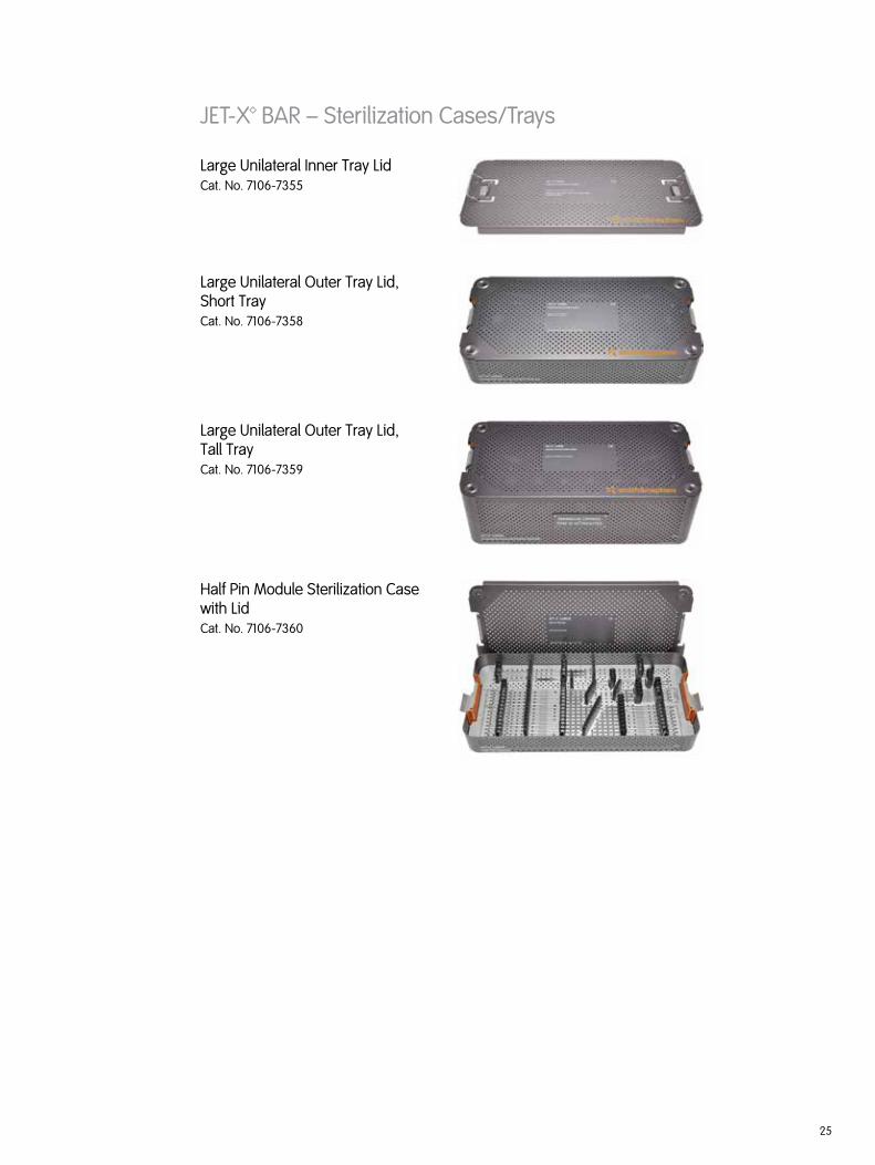
Large Unilateral Outer Tray Lid, Short Tray Cat. No. 7106-7358
Large Unilateral Outer Tray Lid,Tall Tray Cat. No. 7106-7359
Half Pin Module Sterilization Case with LidCat. No. 7106-7360
Large Unilateral Inner Tray LidCat. No. 7106-7355

26
JET-X™ BAR – Kits
Ankle Spanning Kit –Multiple Clamp with TiN Half Pin, Sterile*Kit No. 7106-2701
Ankle Spanning Kit –Single Clamp with TiN Half Pin, Sterile*Cat. No. 7106-2702
Travel Traction Kit –600mm Bar with TiN Traction Pin, Sterile*Cat. No. 7106-2703
Tibia Kit –350mm Bar with TiN Half Pin, Sterile*Cat. No. 7106-2705
Ankle Spanning Kit –Standard Central Body with TiN Half Pins, Sterile*Cat. No. 7105-1701
Sterile Kit for JET-X MINI Bar Distal Radius KitCat. No. 7106-4701

27
Original JET-X™ MINI – Instruments
4mm Trocar Cat. No. 7106-3212
8mm Ratchet WrenchCat. No. 7106-3210
Drill GuideCat. No. 7106-3211
AO T-Handle Connector with 10mm SocketCat. No. 7106-3001
10mm Ratchet Cat. No. 7106-3003
3.5mm Drill with AO ConnectorCat. No. 7106-3006
Drill for 3mm Short Half Pins Cat. No. 7106-3203
Drill for 4mm Short Half Pins Cat. No. 7106-3204
Combination Mini Drill Sleeve/ Tissue ProtectorCat. No. 7106-3205
Multiple Pin ClampCat. No. 7106-4015

28
JET-X™ Half Pins – Implants
Titanium Nitride Long Half Pins, Non-SterileThreadDiam
ShankDiam
ThreadLength
ShankLength*
7106-5309 5mm 5mm 30mm 160mm
7106-5359 5 5 35 160
7106-5409 5 5 40 160
7106-5459 5 5 45 160
7106-5509 5 5 50 160
7106-5559 5 5 55 160
7106-5609 5 5 60 160
ThreadDiam
ShankDiam
ThreadLength
ShankLength*
7106-5659 5mm 5mm 65mm 160mm
7106-5709 5 5 70 160
7106-6409 6 6 40 160
7106-6459 6 6 45 160
7106-6509 6 6 50 160
7106-6559 6 6 55 160
7106-6609 6 6 60 160
Titanium Nitride Short Half Pins, Non-SterileThreadDiam
ShankDiam
ThreadLength
ShankLength*
7106-3108 3mm 4mm 10mm 65mm
7106-3158 3 4 15 65
7106-3208 3 4 20 65
7106-3258 3 4 25 65
7106-4158 4 4 15 95
7106-4208 4 4 20 95
7106-4258 4 4 25 95
7106-4308 4 4 30 95
7106-4358 4 4 35 95
ThreadDiam
ShankDiam
ThreadLength
ShankLength*
7106-5308 5mm 5mm 30mm 110mm
7106-5358 5 5 35 110
7106-5408 5 5 40 110
7106-5458 5 5 45 110
7106-5508 5 5 50 110
7106-5558 5 5 55 110
7106-5608 5 5 60 110
7106-5658 5 5 65 110
7106-5708 5 5 70 110
Titanium Nitride Extra Short Half Pins, Non-SterileThreadDiam
ShankDiam
ThreadLength
ShankLength*
7106-5304 5mm 5mm 30mm 65mm
7106-5354 5 5 35 65
ThreadDiam
ShankDiam
ThreadLength
ShankLength*
7106-5404 5mm 5mm 40mm 65mm
7106-5454 5 5 45 65
*Pin length does not include AO Connector or threads. AO Connector length is 23.65mm

29
JET-X™ Half Pins – Implants
Titanium Traction Pin, Sterile ThreadDiam
ShankDiam
ThreadLength
ShankLength**
7105-5503 5mm 5mm 50mm 375mm
Titanium Nitride Long Traction Pin, Sterile ThreadDiam
ShankDiam
ThreadLength
ShankLength**
7106-5507S 7mm 5mm 50mm 375mm
Titanium Nitride Short Traction Pin, Sterile ThreadDiam
ShankDiam
ThreadLength
ShankLength**
7106-5504S 7mm 5mm 50mm 223mm
Titanium Nitride Half Pin with 1.6mm Cannulation, SterileThreadDiam
ShankDiam
ThreadLength
ShankLength**
7106-5407S 5mm 5mm 40mm 110mm
Titanium Nitride Cannulated Half Pin with 1.6mm Guide Wire, Sterile* ThreadDiam
ShankDiam
ThreadLength
ShankLength**
7106-5400 5mm 5mm 40mm 110mm
**Pin length does not include AO Connector or threads; AO Connector length is 23.65mm*Not currently available in the US

30
Large Bar SetSet No. 7106-7453
Description Qty
7106-2100 100mm Bar 2
7106-2150 150mm Bar 3
7106-2160 L Bar 2
7106-2180 V Bar 1
7106-2200 200mm Bar 3
7106-2250 250mm Bar 3
7106-2300 300mm Bar 4
7106-2350 350mm Bar 4
7106-2400 400mm Bar 4
7106-5507 TiN 5mm x 50mm Traction Pin 3
7106-7351 Bar Module 1
Combination (Freedom/Quick) SetSet No. 7106-7452
Description Qty
7106-2721 Freedom Ankle Clamp 1
7106-2722 Freedom Clamp 10.5mm to Ring 2
7106-4001 Freedom Clamp 10.5mm Bar to 5mm Pin
8
7106-4002 Freedom Clamp 10.5mm Bar to 10.5mm Bar
8
7106-4019 Freedom Clamp 10.5mm Bar to 6mm Pin
2
7106-7350 Clamp Module 1
7106-7355 Inner Tray Lid 1
7106-7372 Quick Clamp 10.5mm Bar to 5mm Pin 8
7106-7373 Quick Clamp 10.5mm Bar to 6mm Pin 2
7106-7374 Quick Clamp 10.5mm Bar to 10.5mm Bar
8
7106-7375 4 Hole Pin Clamp 2
7106-7376 6 Hole Pin Clamp 2
7106-7379 Straight Post 2
7106-7381 30º Angled Post 2
7106-7382 Freedom Post 6
JET-X™ BAR – Sets

31
Large Instrument SetSet No. 7106-7454
Description Qty
102907 Wrench, 10mm Flex Head 1
7106-3004 AO to Hall Adapter 1
7106-7306 Trocar, 5mm/6mm Long 1
7106-7307 Trocar, 5mm/6mm Short 1
7106-7308 Trocar, 5mm/6mm Extra Short 1
7106-7310 Tissue Protector Handle 2
7106-7312 5mm/6mm Tissue Protector for Long Half Pin
2
7106-7313 5mm/6mm Tissue Protector for Short Half Pin
2
7106-7314 5mm/6mm Tissue Protector for Extra Short Half Pin
2
7106-7317 Drill for Extra Short 5mm Half Pin 2
7106-7318 Drill for Short 5mm Half Pin 2
7106-7319 Drill for Long 5mm Half Pin 2
7106-7320 Drill for Short 6mm Half Pin 2
7106-7321 Drill for Long 6mm Half Pin 2
7106-7322 10mm Ratchet Wrench 1
7106-7324 Quick Clamp Bar to Pin Drill Guide 1
7106-7326 AO T-Handle Connect with 10mm Socket 1
7106-7352 Large Partial Half Pin Instrument Module 1
7106-7358 Outer Tray 1
JET-X™ BAR – Sets

32
Long Half Pin SetSet No. 7106-7456
Description Qty
7106-5309 TiN 5mm x 30mm 8
7106-5359 TiN 5mm x 35mm 8
7106-5409 TiN 5mm x 40mm 6
7106-5459 TiN 5mm x 45mm 6
7106-5504 TiN 5mm x 50mm Short Traction Pin 2
7106-6409 TiN 6mm x 40mm 4
7106-6509 TiN 6mm x 50mm 4
Short Half Pin SetSet No. 7106-7455
Description Qty
7106-5308 TiN 5mm x 30mm 8
7106-5358 TiN 5mm x 35mm 8
7106-5408 TiN 5mm x 40mm 8
7106-5458 TiN 5mm x 45mm 6
7106-5504 TiN 5mm x 50mm Short Traction Pin 2
7106-6409 TiN 6mm x 40mm 4
7106-6509 TiN 6mm x 50mm 4
JET-X™ Half Pins – Sets

33
Complete 5mm /6mm Half Pin Add On SetSet No. 7106-7457
Description Qty
7105-1039 1.6mm x 240mm Wire 1
7106-5304 TiN 5mm x 30mm Extra Short 2
7106-5354 TiN 5mm x 35mm Extra Short 2
7106-5404 TiN 5mm x 40mm Extra Short 2
7106-5407 TiN 5mm x 40mm 1.6mm Cann Half Pin 1
7106-5454 TiN 5mm x 45mm Extra Short 2
7106-5508 TiN 5mm x 50mm Short Half Pin 2
7106-5509 TiN 5mm x 50mm Long Half Pin 2
7106-5558 TiN 5mm x 55mm Short Half Pin 2
7106-5559 TiN 5mm x 55mm Long Half Pin 2
7106-5608 TiN 5mm x 60mm Short Half Pin 2
7106-5609 TiN 5mm x 60mm Long Half Pin 2
7106-5658 TiN 5mm x 65mm Short Half Pin 2
7106-5659 TiN 5mm x 65mm Long Half Pin 2
7106-5708 TiN 5mm x 70mm Short Half Pin 2
7106-5709 TiN 5mm x 70mm Long Half Pin 2
7106-6409 TiN 6mm x 40mm 2
7106-6459 TiN 6mm x 45mm 2
7106-6509 TiN 6mm x 50mm 2
7106-6559 TiN 6mm x 55mm 2
7106-6609 TiN 6mm x 60mm 2
7106-7360 Half Pin Module Sterile Case with Lid 1
JET-X™ Half Pins – Sets
Auxiliary Instrument SetSet No. 7106-7458
Description Qty
7106-3002 Distractor Clip 2
7106-3005 AO to Trinkle Adapter 1
7106-3009 Distraction Instrument 1
7106-3010 5mm Bar To Pin Guide 1
7106-3011 1.6mm Wire Guide 1
7106-3013 3.5mm/1.6mm Cannulated Drill 1
7106-3017 5mm Cannulated Pin Tissue Protector 1
7106-3018 3.5mm Cannulated Pin Drill Sleeve 1
7106-7354 Auxiliary Instrument Case with Lid 1

34
MINI Distal Radius SetSet No. 7106-7459
Description Qty
102915 Box Wrench, SBF 8mm 1
290058 Protective Caps, Red for Threaded 4mm Pin 6
7106-2016 Mini Double Pin Clamp with Ball Joint 2
7106-3152 Half Pin, 3mm x 15mm 2
7106-3202 Half Pin, 3mm x 20mm 2
7106-5225 6mm x 225mm Bar 1
7106-7327 2.0mm Drill 1
7106-7328 Double Pin Drill Sleeve 2
7106-7329 Double Pin Drill Guide 1
7106-7330 Pin Driver 1
7106-7362 Module Tray 1
7163-1186 Mini Connector 1
JET-X™ MINI – Sets

35
JET-X™ MINI – SetsMINI Instrument and Clamp SetSet No. 7106-7462
Description Qty
102915 Box Wrench SBF 1
7106-3004 AO to Hall Adapter 1
7106-3108 TiN Half Pin 3mm x 10mm 4
7106-3158 TiN Half Pin 3mm x 15mm 4
7106-3208 TiN Half Pin 3mm x 20mm 4
7106-3258 TiN Half Pin 3mm x 25mm 4
7106-4010 Freedom Clamp, 10.5mm to 4mm Pin 2
7106-4011 Freedom Clamp, 6mm to 4mm Pin 3
7106-4012 Freedom Clamp, 6mm to 6mm Bar 3
7106-4019 Freedom Clamp, 10.5mm to 6mm Pin 2
7106-4158 TiN Half Pin 4mm x 15mm 4
7106-4208 TiN Half Pin 4mm x 20mm 4
7106-4258 TiN Half Pin 4mm x 25mm 4
7106-4308 TiN Half Pin 4mm x 30mm 4
7106-4358 TiN Half Pin 4mm x 35mm 4
7106-5075 6mm x 75mm Bar 2
7106-5110 6mm x 110mm Bar 2
7106-5180 V-Bar 6mm 1
7106-5185 6mm x 185mm Bar 2
7106-5225 6mm x 225mm Bar 4
7106-7305 AO T-Handle Connector with 8mm Socket 1
7106-7309 Trocar 1
7106-7310 Tissue Protector Handle 2
7106-7311 Tissue Protector 2
7106-7315 Drill for 3mm Half Pin 2
7106-7316 Drill for 4mm Half Pin 2
7106-7322 10mm Ratchet Wrench 1
7106-7323 8mm Ratchet Wrench 1
7106-7325 Quick Clamp Bar to in Drill Guide 1
7106-7361 Tray 1
7106-7371 Quick Clamp 10.5mm to 4mm Pin 2
7106-7373 Quick Clamp 10.5mm to 6mm Pin 2
7106-7377 Quick Clamp 6mm to 4mm Pin 3
7106-7378 Quick Clamp 6mm to 6mm Bar 3

36
Sterilization/Resterilization
External Fixation Devices and Instruments
Unless specifically labeled sterile, the external fixation devices and instruments are supplied non-sterile and must be sterilized prior to use. “JET-X™ Bar Kits” (Ankle Spanning Kit, Travel Traction Kit and other kits listed in this brochure) are supplied sterile and have been sterilized by ethylene oxide gas. All radiation sterilized components have been exposed to a minimum of 25 kilo Grays of gamma radiation. The method of sterilization is noted on the package label.
External fixation devices are considered single use devices. The external fixation devices may be steam sterilized using the following validated cycles and parameters:
Dynamic air removal (prevacuum) steam
• Exposure temperature: 132ºC (270ºF); Minimum exposure time: 4 minutes
OR
• Exposure temperature: 135ºC (275ºC); Minimum exposure time: 3 minutes
• Minimum drying time: Wrapped devices – 15 minutes; containerized devices –30 minutes
For non-US customers
UK steam cycle
• Prevacuum cycle
• Exposure temperature: 134°C (273ºF)
• Exposure time: 3 minutes
• Vacuum drying: 30 minutes
Note The procedure outlined in HTM 2010 should be followed
World Health Organization (WHO) steam cycle
• Exposure temperature: 134ºC (273ºF)
• Exposure time: 18 minutes
• Vacuum drying: 30 minutes
Instruments (reusable devices) may be steam sterilized using the same cycles above and also the following validated cycles and parameters:
Gravity displacement steam
• Exposure temperature: 132ºC (270ºF)
• Exposure time:
- 15 minutes for wrapped devices
- 30 minutes for containerized devices
• Purge: 1 minute
• Minimum vacuum drying: 30 minutes
Immediate Use Steam Sterilization (IUSS) or Flash Steam
• Exposure temperature: 132ºC (270ºF)
• Exposure time: - Gravity displacement: 15 minutes - Dynamic air removal (prevacuum): 4 minutes

37
Half Pins and Wires
Half pins and wires are considered implants and are therefore single use devices. These devices are sold both sterile and nonsterile. The sterile devices are often removed from their original packaging and placed in a containment device for processing. Used implants cannot be reprocessed for use. The validated steam sterilization cycles and parameters are as follows:
Dynamic air removal (prevacuum) steam
• Exposure temperature: 132°C (270°F); Minimum exposure time: 4 minutes
OR
• Exposure temperature: 135ºC (275ºF); Minimum exposure time: 3 minutes
• Minimum drying time: Wrapped devices – 15 minutes; containerized devices –30 minutes
Gravity displacement steam
• Exposure temperature: 132ºC (270ºF)
• Exposure time: - 15 minutes for wrapped devices - 30 minutes for containerized devices
• Purge: 1 minute
• Minimum vacuum drying: 30 minutes

©2012 Smith & Nephew, Inc. All rights reserved. 7108-0632 REV0.1 09/12
Smith & Nephew, Inc.7135 Goodlett Farms ParkwayCordova, TN 38016USA
Telephone: 1-901-396-2121Information: 1-800-821-5700Orders/inquiries: 1-800-238-7538
www.smith-nephew.com
™Trademark of Smith & Nephew. Reg. US Pat. & TM Off.