animation of dressed virtual humans
TRANSCRIPT

ANIMATION OF DRESSED VIRTUALHUMANS
a thesis
submitted to the department of computer engineering
and the institute of engineering and science
of bilkent university
in partial fulfillment of the requirements
for the degree of
master of science
By
Ilknur Kaynar Kabul
July, 2004

I certify that I have read this thesis and that in my opinion it is fully adequate,
in scope and in quality, as a thesis for the degree of Master of Science.
Prof. Dr. Bulent Ozguc (Advisor)
I certify that I have read this thesis and that in my opinion it is fully adequate,
in scope and in quality, as a thesis for the degree of Master of Science.
Assist. Prof. Dr. Ugur Gudukbay (Co-advisor)
I certify that I have read this thesis and that in my opinion it is fully adequate,
in scope and in quality, as a thesis for the degree of Master of Science.
Prof. Dr. Ozgur Ulusoy
Approved for the Institute of Engineering and Science:
Prof. Dr. Mehmet B. BarayDirector of the Institute
ii
ABSTRACT
ANIMATION OF DRESSED VIRTUAL HUMANS
Ilknur Kaynar Kabul
M.S. in Computer Engineering
Supervisors: Prof. Dr. Bulent Ozguc and
Assist. Prof. Dr. Ugur Gudukbay
July, 2004
In this study, we present a system that enables the simulation of a dressed
virtual human with different motion behaviors. The proposed system is composed
of three modules: human body motion module, garment design module, and
garment simulation module. The human body motion module enables the user
to design different motion behaviors by adjusting the motion patterns for each
body part. The garment design module consists of creating garment patterns,
setting their sizes, and cutting them by removing particles. The adjustment of
garment patterns onto human body is achieved by seaming garment patterns
while applying cloth deformation and collision handling. Garment simulation
module provides animation of virtual humans with the garments on. The main
problem in garment simulation is collision handling between the animated virtual
human and its garments. This study focuses on this problem. Collision detection
calculations are reduced by using bounding volumes for both virtual human and
garments. In addition, for avoiding edge-edge collision detection, a heuristic that
constructs a very thin volume around the human body is applied. For the collision
response, penalty forces and constraints are applied depending on the distance
between the particle and the triangle’s plane, and the particle’s position with
respect to triangle. Visual results and performance experiments produced by the
implementation are presented.
Keywords: mass-spring model, garment design, garment simulation, collision han-
dling, cloth.
iii
OZET
GIYDIRILMIS INSAN MODELLERININ ANIMASYONU
Ilknur Kaynar Kabul
Bilgisayar Muhendisligi, Yuksek Lisans
Tez Yoneticileri: Prof. Dr. Bulent Ozguc ve
Yrd. Doc. Dr. Ugur Gudukbay
Temmuz, 2004
Bu calısmada, kıyafet giydirilmis insan modelinin degisik hareket bicimleriyle
benzetimini saglayan bir sistem sunulmaktadır. Onerilen sistem uc modulden
olusmaktadır: Vucut hareketleri modulu, kıyafet tasarım modulu, kıyafet ben-
zetim modulu. Vucut hareketleri modulu, kullanıcının her vucut parcası icin
farklı hareket sablonlarını duzenlemesini ve boylece cesitli hareket bicimlerini
tasarlamasını saglamaktadır. Kıyafet tasarım modulu, kıyafet modellerinin
olusturulmasını, olculerinin belirlenmesini ve parcacık cıkarılmasıyla kesilmesini
icermektedir. Kıyafetin insan modeli uzerine giydirilmesi, kumasın deforme ol-
ması ve cakısmaların ele alınması sırasında kıyafet parcalarının dikilmesi ile
yapılmaktadır. Kıyafet benzetim modulu kıyafet giymis insan modelinin hareket
ettirilmesini saglamaktadır. Bu moduldeki en onemli problem hareketli insan
modeli ile kıyafet modeli arasındaki cakısmaların ele alınması ve onlenmesidir.
Bu calısmada bu problem uzerinde durulmaktadır. Cakısmaların belirlenmesin-
deki hesaplamalar insan ve kumas modelleri icin kısıtlayan hacimler kullanılması
yoluyla azaltılmıstır. Ayrıca kenar-kenar kesisimlerinin hesaplanmasını onlemek
icin insan vucudu uzerinde kucuk bir hacim olusturulmustur. Cakısmaların
onlenmesi icin kumas parcacıgı ile ucgen duzlemi arasındaki uzaklıga ve parcacıgın
ucgene gore pozisyonuna baglı olarak ceza kuvvetleri ve sınırlamalar uygu-
lanmıstır. Gerceklestirilen sistem ile olusturulan gorsel sonuclar ve basarım
sonucları tezde sunulmustur.
Anahtar sozcukler : kutle-yay sistemleri, kıyafet tasarımı, kıyafet benzetimi,
carpısma testi, kumas.
iv

Acknowledgement
I am gratefully thankful to my supervisors Prof. Dr. Bulent Ozguc and
Assist. Prof. Dr. Ugur Gudukbay for their supervision, guidance, and sugges-
tions throughout the development of this thesis. I would also like to give special
thanks to my thesis committee member Prof. Dr. Ozgur Ulusoy for his valuable
comments.
I would also like to thank Funda Durupınar for her invaluable support and
for implementing the testbed for my research. And very special thanks to my
spouse, Mustafa Onur Kabul, for his patience and support.
v
Contents
1 Introduction 1
1.1 Our Approach . . . . . . . . . . . . . . . . . . . . . . . . . . . . . 2
1.2 The System Overview . . . . . . . . . . . . . . . . . . . . . . . . 3
1.3 Organization of the Thesis . . . . . . . . . . . . . . . . . . . . . . 4
2 Background 6
2.1 State of Art in Garment Design . . . . . . . . . . . . . . . . . . . 6
2.2 State of Art in Garment Simulation . . . . . . . . . . . . . . . . . 8
2.3 Simulation of cloth behavior . . . . . . . . . . . . . . . . . . . . . 11
2.4 Integration Methods . . . . . . . . . . . . . . . . . . . . . . . . . 11
2.5 Collision Handling . . . . . . . . . . . . . . . . . . . . . . . . . . 12
2.5.1 Collision Detection . . . . . . . . . . . . . . . . . . . . . . 13
2.5.2 Collision Response . . . . . . . . . . . . . . . . . . . . . . 21
3 Human Body Motion Module 24
3.1 Human Body Model . . . . . . . . . . . . . . . . . . . . . . . . . 24
vi
CONTENTS vii
3.2 Human Body Motion . . . . . . . . . . . . . . . . . . . . . . . . . 26
3.2.1 Motion Control for the Skeleton Layer . . . . . . . . . . . 26
3.2.2 Motion of the Human Layers . . . . . . . . . . . . . . . . . 26
4 Garment Design Module 29
4.1 Creating Garment Panels . . . . . . . . . . . . . . . . . . . . . . . 30
4.2 Cutting Garment Panels . . . . . . . . . . . . . . . . . . . . . . . 30
4.3 Garment Placement . . . . . . . . . . . . . . . . . . . . . . . . . . 30
4.4 Sewing Garment Panels . . . . . . . . . . . . . . . . . . . . . . . 30
4.5 Deformation of Garment . . . . . . . . . . . . . . . . . . . . . . . 31
4.5.1 Surface topology . . . . . . . . . . . . . . . . . . . . . . . 32
4.5.2 Evolving a mass-spring system . . . . . . . . . . . . . . . . 32
5 Garment Simulation Module 36
5.1 Collision Detection Between Garment and Human Body . . . . . 36
5.1.1 Bounding Volume Hierarchy for the Cloth Model . . . . . 37
5.1.2 Bounding Volumes for the Human Model . . . . . . . . . . 38
5.1.3 Collision Detection between Bounding Volumes of Human
Model and Cloth Model . . . . . . . . . . . . . . . . . . . 43
5.1.4 Geometrical Collision Detection . . . . . . . . . . . . . . . 45
5.2 Self-Collision Detection . . . . . . . . . . . . . . . . . . . . . . . . 48
5.3 Collision Response . . . . . . . . . . . . . . . . . . . . . . . . . . 49
CONTENTS viii
5.3.1 Case 0: No intersection . . . . . . . . . . . . . . . . . . . . 50
5.3.2 Case 1: Point-Triangle Proximity . . . . . . . . . . . . . . 50
5.3.3 Case 2: Point-Triangle Intersection . . . . . . . . . . . . . 51
5.3.4 Case 3: Point-Triangle Interference . . . . . . . . . . . . . 53
6 Results 55
6.1 Visual Results . . . . . . . . . . . . . . . . . . . . . . . . . . . . . 55
6.2 Performance Analysis . . . . . . . . . . . . . . . . . . . . . . . . . 57
6.2.1 Comparison of Collision Detection Approaches . . . . . . . 58
6.2.2 Comparison of Bounding Volumes For the Human Model . 59
7 Conclusion 65
A The System At Work 72
A.1 Overview . . . . . . . . . . . . . . . . . . . . . . . . . . . . . . . . 72
A.2 The Main Menu . . . . . . . . . . . . . . . . . . . . . . . . . . . . 73
A.3 The Motion Control, Skinning, Garment Design and Simulation
Toolbox . . . . . . . . . . . . . . . . . . . . . . . . . . . . . . . . 74
A.4 The Keyframe Editor . . . . . . . . . . . . . . . . . . . . . . . . . 75
A.5 Garment Design Editor . . . . . . . . . . . . . . . . . . . . . . . . 76
A.6 The Viewing Area . . . . . . . . . . . . . . . . . . . . . . . . . . . 76
List of Figures
1.1 The system architecture . . . . . . . . . . . . . . . . . . . . . . . 4
5.1 Axis aligned bounding boxes for the cloth model . . . . . . . . . . 38
5.2 Classification of geometrical primitives (reproduced from [27]). . . 39
5.3 Different kinds of bounding volumes for the human model . . . . 40
5.4 The minimal bounding sphere algorithm (2nd pass) . . . . . . . . 42
5.5 Collision detection test between two OBBs (reprinted from [11]). . 44
5.6 Construction of bounding volume . . . . . . . . . . . . . . . . . . 46
5.7 Collision Response: Case 0 . . . . . . . . . . . . . . . . . . . . . . 50
5.8 Collision Response: Case 1 . . . . . . . . . . . . . . . . . . . . . . 51
5.9 Collision Response: Case 2 . . . . . . . . . . . . . . . . . . . . . . 51
5.10 Interpolation of velocities using barycentric coordinates . . . . . . 52
5.11 Response direction for different particles (Reprinted from [19]) . . 52
5.12 Resolving collisions by manipulating velocities . . . . . . . . . . . 53
5.13 Collision Response: Case 3 . . . . . . . . . . . . . . . . . . . . . . 54
ix
LIST OF FIGURES x
6.1 Still frames of a man, who is raising his leg, with a dress on it . . 56
6.2 Frames of a jumping man wearing a tight dress . . . . . . . . . . 57
6.3 Frames of a man wearing t-shirt and shirt, and wearing dress . . 58
6.4 Images of a man wearing a dress. He is lifting his left leg up. . . 59
6.5 Images of a man wearing a t-shirt and a shirt. He is rotating right,
then left. . . . . . . . . . . . . . . . . . . . . . . . . . . . . . . . 60
6.6 Frames from different animations . . . . . . . . . . . . . . . . . . 61
6.7 Images of a human model with different postures and with different
clothes on it . . . . . . . . . . . . . . . . . . . . . . . . . . . . . 62
6.8 Illustration of falling clothes on a motionless human body . . . . . 62
6.9 Images that demonstrates the deformation of a hanging cloth while
the human body is animated. . . . . . . . . . . . . . . . . . . . . 63
6.10 Self-collisions are not detected when clothes are falling due to the
gravity. . . . . . . . . . . . . . . . . . . . . . . . . . . . . . . . . 63
6.11 Self-collisions are detected and responses are applied. . . . . . . . 63
6.12 Comparison of point-triangle/edge-edge (PT EE) collision detec-
tion with point-triangle/bounding volume (PT BV) . . . . . . . . 64
6.13 Comparison of OBB, AABB and Bounding Sphere approaches for
the human model . . . . . . . . . . . . . . . . . . . . . . . . . . . 64
A.1 Top level user interface of the system (reprinted from [18, 36]). . . 74
A.2 The motion control and the skinning toolbox (reproduced from [36]) 75
A.3 The garment design and simulation toolbox. . . . . . . . . . . . . 76

LIST OF FIGURES xi
A.4 The keyframe editor . . . . . . . . . . . . . . . . . . . . . . . . . 77
A.5 The garment design editor . . . . . . . . . . . . . . . . . . . . . . 77
A.6 The viewing area . . . . . . . . . . . . . . . . . . . . . . . . . . . 78

List of Tables
6.1 Frame rates. Numbers indicate the time (in seconds) for the gen-
eration of a single frame. M stands for the computation of the
skin layer according to the motion of muscle and skeleton layer.
CS means cloth simulation using mass-spring model and CD&R
represents “collision detection and response”. CS&CD&R corre-
sponds to the simulation of cloth and collision handling where four
iteration per frame using fixed time iterations is used. . . . . . . . 57
xii

To my family...
Chapter 1
Introduction
Cloth modelling and simulation is an essential topic in computer animation of
realistic virtual humans. Today computer graphics and textile industry commu-
nities are interested in how to describe and simulate the motions of cloth in a
realistic, stable and efficient way. Furthermore, there exists an increasing demand
from technologies such as character animation, game industry, fashion industry,
and textile industry, which leads the development of new tools that are able to
perform real time and realistic simulations.
The main purposes of the existing systems are the design and simulation of
garments. Garment design systems are mostly used by the fashion and textile
industry for creating various garment patterns that fit to the virtual bodies. They
improve the productivity and efficiency of the manufacturing period by decreasing
the time and amount of materials that are necessary during the design. The
process in these systems is done either by drawing 2D patterns, seaming these
patterns together and putting them on a 3D mannequin, or by designing 3D
garments around a mannequin and generating the 2D patterns of the 3D designed
garment.
Garment simulation is an integral component of virtual character animation.
Its purpose is to create a garment’s deformation based on the motion of the virtual
human. It is mostly used in video games, films, virtual reality applications, textile
1
CHAPTER 1. INTRODUCTION 2
industry and garment based e-commerce applications. In digital movies, such
as ’Shrek’ and ’Monster’s Inc’, the accuracy of the cloth model and its physical
properties are important, because the animations must be believable and realistic.
On the other hand, garment-related e-commerce systems and computer games
require interactivity, efficiency and flexible manipulation. In computer games,
simple cloth models are mostly used to give the appearance and look of the
cloth, since the purpose is not simulating the cloth accurately. In e-commerce
applications, both correctness and efficiency of the cloth model is important,
because these systems enable the user to visualize the clothes, to animate and to
predict the motion behavior of them, and to view garments fitted onto their own
virtual bodies. These systems require interactivity since they support customers
in decision-making by selecting various garments and fit these garments onto the
3D mannequin that is adjusted according to his/her measurements. Up to now,
much research has been done on garment simulation and significant advances
have been achieved. However, still a deeper study of the cloth model and the
simulation of it in different applications are necessary.
1.1 Our Approach
In this study, we describe a system to simulate the deformation of various garment
material types and to deform the garments along with the character’s motion. For
the first one, various types of fabric and shading modes, including knitwear and
woven cloth, are simulated. In addition, the 3D construction of a garment from
different garment panels through cutting and seaming processes are handled. The
details of cloth rendering and garment design in our implementation are explained
in [8].
This study focuses on the animation of virtual humans with the garments on.
There are two important parts in our study, one is to create the deformation of
garment realistically and the other is to create the deformation of garments along
the character’s motion.
CHAPTER 1. INTRODUCTION 3
The system is built on top of a human modelling and animation tool [18, 36]
that uses a human body model composed of three layers: a skeleton layer, a muscle
layer, and a skin layer. In this tool, the motion of the skeleton and the muscle
layer is calculated using inverse kinematics approach. The skin layer moves with
the skeleton and is modelled by irregular triangle meshes.
A mass-spring model having a polygonal structure is used for the cloth model.
While the human model is moving, we solve the equations for the motion of the
cloth by taking into account its collision with the skin layer of the human body.
We use explicit Euler’s integration method to solve the equations. We consider
external forces such as gravity, wind, etc. and internal spring forces used to
deform the cloth.
In order to achieve garment simulation on a virtual human, firstly the motion
of the human model is constructed by adjusting the motion patterns for each
body part. Then, the garment panels are designed and placed around the human
model. They are adjusted to the human body by applying forces to the seaming
particles. Finally, the dressed character is animated together with its garments.
In our study, we examine the collision detection and response in detail since it is
an integral part in the animation of dressed character. We utilize bounding box
techniques, both for cloth and human models, and we compare the efficiencies of
them. Furthermore, we reduce the collision detection calculations by using some
heuristics, like bounding volumes [37] . In this way, we avoid edge-edge collisions
and only used point-triangle collision detection method. We apply combination
of penalty forces and constraints for the collision response. The type of collision
response is determined depending on the distance between the particle and the
triangle’s plane, and the position of the particle with respect to the human body.
1.2 The System Overview
Our system is composed of three modules: human body motion design, garment
design, and garment simulation modules. Human body motion design module
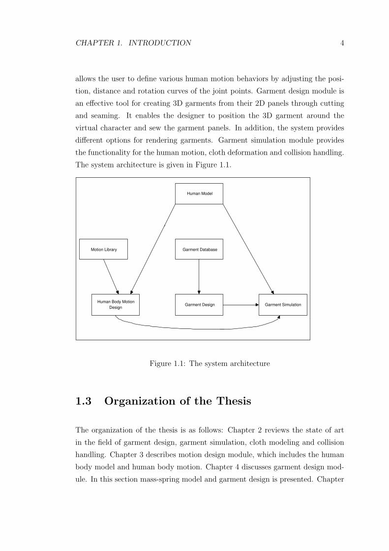
CHAPTER 1. INTRODUCTION 4
allows the user to define various human motion behaviors by adjusting the posi-
tion, distance and rotation curves of the joint points. Garment design module is
an effective tool for creating 3D garments from their 2D panels through cutting
and seaming. It enables the designer to position the 3D garment around the
virtual character and sew the garment panels. In addition, the system provides
different options for rendering garments. Garment simulation module provides
the functionality for the human motion, cloth deformation and collision handling.
The system architecture is given in Figure 1.1.
Human Model
Motion Library Garment Database
Human Body Motion
Design Garment Design Garment Simulation
Figure 1.1: The system architecture
1.3 Organization of the Thesis
The organization of the thesis is as follows: Chapter 2 reviews the state of art
in the field of garment design, garment simulation, cloth modeling and collision
handling. Chapter 3 describes motion design module, which includes the human
body model and human body motion. Chapter 4 discusses garment design mod-
ule. In this section mass-spring model and garment design is presented. Chapter

CHAPTER 1. INTRODUCTION 5
5 provides the garment simulation module. It gives detailed information about
the collision detection and the collision response part. Chapter 6 gives the visual
and performance results of the system. Chapter 7 presents conclusion and pro-
poses future research. In Appendix A, the implementation details are given and
the functionality of the different parts of the system are described.

Chapter 2
Background
Garment design and simulation become crucial for industries such as movie indus-
try, and fashion-design industry. The need of movie industry is to have realistic
animated characters in its productions. On the other hand, garment companies
want to shorten the design cycle of new styles and reduce the trial and error
process. They would like to build prototypes of garments for evaluating a de-
sign without producing it. In addition, they would like to develop virtual try-on
applications to make their customers see how a garment looks on their body
measures.
Today, there exist systems for the garment design and garment simulation. In
the following sections, state of art and main tasks in both fields will be presented.
2.1 State of Art in Garment Design
In the last decade, various software tools that enable 2D painting, 2D handling,
grading, and nesting are developed. The purpose of all these systems is to save
time and material. However, these systems do not provide the designer to work
directly in a 3D environment in a whole process of garment design.
Therefore, 3D computer-based systems have been developed. The target of
6

CHAPTER 2. BACKGROUND 7
these systems is to reduce the design process of a new garment, to create methods
that make the customer to see how a garment fits and looks on his/her body, to
improve the productivity of the apparel industry by reducing the time of design
and to increase the creativity potential of the designer.
In these systems garment design process is done in two different ways:
• Drawing 2D patterns, sewing these patterns together and putting them on
a 3D virtual character.
• Designing 3D garments around a virtual character and generating the 2D
patterns of the 3D designed garment.
Many systems have been proposed for the garment industry since the 1990s.
The system that is presented in [35] is one of the initial design tools that is
based on the first condition mentioned above. This tool enables the design of
the garment panels in 2D, sews the garment panels in 3D, and simulates the
garment’s behavior dynamically on the moving body of a virtual character. In
addition, the system lets the user to do modifications on the 2D patterns in case
the 3D garment is not fitting. In the system, there exists a connection between
the program and the cutting machine, which provides the transmission of the
final design to the cutting machine.
As an example for the second garment design process, the system that is
presented in [6] can be given. [6] presents a 3D graphics environment to design
and simulate men garments according to the fabric properties and manufacturing
processes. The design of the men garment is achieved firstly by doing the design
of 3D garments around the mannequin, in particular jackets, together with the
style of garments. Then, the 2D garment patterns are generated from the 3D
representation. The 3D garment design module is based on the use of MAYA
Deformers, and the 3D garment simulator relies on particle-based approach. The
results of this system demonstrate that the approach is effective for representing
the clothes in industrial applications.
In addition, in the recent years [34] proposes a new feature-based 3D garment

CHAPTER 2. BACKGROUND 8
design system that can greatly improve the efficiency and the quality of pattern
making in the garment industry. The system enables intuitive modeling of a 3D
garment around a human model using 2D sketches input. The constructed gar-
ment surfaces are related to the predefined features on human body. The steps
in the system are (1) construction of a garment feature template according to
the features on the human model; (2) 3D profile definition through 2D sketches;
(3) construction of a smooth mesh surface, which can be cut and flattened into
2D patterns to be manufactured, interpolating the specified 3D profiles. The
system has several advantages compared to the earlier approaches. Firstly, the
system provides direct design of garment patterns through 2D patterns in the
3D space. In addition, when the same style of garment is wanted to be created
for other feature based human models, the patterns can be regenerated automat-
ically because the constructed 3D garment patterns are related to the features
on a human model. Tight garments and loose garments can be constructed by
adjusting the easing space between the specified profiles and the cross-section of
a human model. Furthermore, the 2D sketched input method provided in the
system benefits the designers since most designers still prefer to express their
creative design ideas through 2D sketches.
2.2 State of Art in Garment Simulation
Nowadays, garment simulation becomes important for the garment based e-
commerce applications, movie industry, game industry and textile industry. The
needs of all these industries differ in terms of the applications’ efficiency and accu-
racy. The movie industry wants realistic animations without any time limitation.
On the other hand, garment based e-commerce applications require flexible ma-
nipulation, fast transmission and efficient storage of the display content. The
most critical limitation in these systems is the real-time performance constraint.
Accordingly many approaches have been proposed for several applications.
For example, online clothing stores are designed in order to improve the customer
satisfaction and to reduce the time and costs for manufacturers and retailers.
CHAPTER 2. BACKGROUND 9
In these virtual stores, garment simulation and visualization are handled. For
this purpose rendering of garment panels, simulation of garments using dynamic
laws, and handling the interaction between garments and virtual characters are
involved in the systems. [22] presents a system for producing 3D clothes with
realistic behavior. The main purpose of the system is to build an interactive and
realistic virtual shop, where customers can select the garment designs that they
want to buy and can see these garments on virtually animated bodies. Using
the system, the user can create the standard virtual bodies, which form the basis
for garment modeling. Then the 2D garment patterns are created and seamed
together around the virtual human body. This provides the initial shape of the
garment. Next, the virtual body is animated according to the Optical Motion
Capture data and the cloth is simulated according to the physical parameters and
the animation of virtual body. As a result, the whole system gives the customer
to visualize clothes, to animate them, and to add interactivity in addition to view
garments fitted onto their own virtual bodies. The main problem in that system
is that the simulation of garment movement is performed using physics based
model, and it is impossible to achieve the real-time performance. Therefore, the
simulation results are prerecorded in order to display the animated garment at
an interactive rate.
Later, [5] presents a Web application that integrates several key technolo-
gies into a distributed, interactive virtual clothing store. The system provides a
number of efficient and interactive applications, such as the shopper can select
various garments and fit these garments onto the 3D mannequin that is adjusted
according to his/her measurements. Moreover, the movement of the garment is
simulated to give the shopper an idea about how the garment will look on his/her
body. The main difference of this system from the one presented in [22] is that
the garment simulation is calculated on the fly while keeping the response time
interactive. The system sends body/garment sizing as well as cloth/skin anima-
tion to the client side. Then, the major part of the content to be manipulated is
generated on the client side rather than on the server, which provides a minimal
response time to the user. Furthermore, a significant step in this system is the
application of 3D graphics technology to create and simulate the virtual store.
CHAPTER 2. BACKGROUND 10
Virtual Try-On project [12] leads the development of new VR technologies
that forms the basis of a realistic, three dimensional simulation and visualization
of garments put on virtual counterparts of real customers. The complete process
chain starts with the 3D scanning of the human body up to a photo-realistic 3D
presentation of the virtual customer dressed in the selected pieces of garments.
In general, the main subtasks in a garment simulation and visualization system
are:
• Selection of garment patterns and characters that will interact with the
garments;
• Rendering of the garment patterns;
• Simulation of garment patterns by using dynamic laws simulation (forces,
accelerations, velocities, energies);
• Interaction of garment patterns with the objects in the environment, and
between different parts of the garment (collision detection and response)
Among all the systems mentioned above, simulation of garment patterns by
using dynamic laws simulation and interaction of garment patterns with the hu-
man body require dealing with the following problems:
• Simulation of cloth behavior: The behavior of garment panels is approxi-
mated according to the mechanical models. These models can be physically
based models that allow different material simulation (e.g., cotton, wool,
silk...), or they can be geometrical models that aim to simulate the look of
the cloth.
• Integration methods: When forces acting on the particle are computed, it
is easy to calculate the particle’s acceleration by using the Newton’s law:−→f = m−→a given the mass of the particle. Considering the acceleration is
constant during ∆t, the job becomes to calculate the position and velocity
of the particle at time t+∆t by using integration techniques. For animation
CHAPTER 2. BACKGROUND 11
purposes, the challenge is to find an integration technique that keeps the
results visually pleasing and numerically stable, while being fast enough for
use in real-time applications.
• Collision Handling: It consists of collision detection and collision response.
Collision detection concerns the interactions between garment and hu-
man body as well as garment panels themselves. Collision response is a
physically-based reaction that avoids interpenetration and simulates fric-
tion and bouncing effects.
2.3 Simulation of cloth behavior
Initial work on the simulation of cloth concentrated on the geometrical features
of deforming cloth, such as folds and creases. As the need for simulating the
physical properties of the cloth increased, physically based approaches have been
proposed. Some of these approaches exploit particles systems for mechanical sim-
ulation [2, 9] while others employ continuous models resolved by finite elements
[10]. Among these techniques particle systems became the preferred approach
in the computer graphics community because of their simplicity, flexibility, and
fidelity/performance ratio. On the other hand, finite elements are chosen in a
few applications that need greatest accuracy since they have high computational
costs. A detailed survey of cloth modelling can be found in [20].
2.4 Integration Methods
Cloth simulation algorithm works by discrete time steps. Numerical techniques
are used for computing the next state of the system given the initial state, time
step and the forces acting on each particle.
Explicit and implicit methods are two existing methods, which are used as
integration techniques:
CHAPTER 2. BACKGROUND 12
• Explicit integration methods such as Euler, Midpoint, or Runge-Kutta are
relatively easy to implement. However, they need very small integration
time steps to guarantee system stability and accuracy.
• Implicit methods are able to use larger steps without loss of stability, but
they are more complex to implement because they need to solve large linear
systems at every integration step. The use of implicit methods in cloth
simulation was first proposed by [1].
The comparison of different integration techniques in terms of efficiency is
presented in [33].
2.5 Collision Handling
Garments interact with the body that wears them or with the other garment
panels. The shape and the movement of the body affect the garments movement.
Thus, in order to obtain realistic simulation of garment panels, collision handling
must be achieved in an accurate and efficient way.
Collision handling consists of two phases:
• Collision detection: Checking the geometrical contacts and proximities be-
tween the objects.
• Collision response: Correcting the velocities and positions of the colliding
objects by applying constraints or forces.
In the following sections, the methods proposed for collision detection, optimiza-
tion of collision detection and collision response are presented.

CHAPTER 2. BACKGROUND 13
2.5.1 Collision Detection
Collision detection is the most time consuming part of the cloth simulation, since
the number of geometrical entities, such as nodes, faces, and edges that the
collision detection algorithm has to handle is large. The complexity problem
leads the development of algorithms that decrease the number of collision tests.
Most of these algorithms make specific assumptions about the objects and design
solutions based on the geometry of the objects. Lin and Gottschalk [15] have
presented an overview of collision detection methods.
The general case of collision detection is the one involving cloth and an object.
A particular case is the self-collision detection or the collision between a garment
panel and the human body.
2.5.1.1 Collision Detection Between Cloth and Human Body
Collision detection between cloth and the human body has been widely studied in
the last decade. Most of these methods use geometrical collision detection meth-
ods with the optimization techniques in order to reduce the number of checks.
Mezger, Kimmerle and Etzmu [19] propose a method by combining and im-
proving the techniques, such as hierarchical bounding volumes [30], collision pre-
diction (proximities) through k-DOPs bounding volumes [14] and heuristics [30].
They improve the efficiency of bounding volume hierarchies by adapted tech-
niques. To prune the hierarchy, extended sets of heuristics, such as curvature and
coherence criteria, are used. In addition, for preserving large time steps and sta-
bility, oriented inflation of bounding volumes is used to detect not only collisions
but also proximities. The advantage of this approach is to detect collisions before
they occur. The results presented at the end of this paper show great efficiency.
A voxel-based collision detection method for clothed human animation is pre-
sented in [37]. They speed up the performance of the voxel-based method by
choosing an appropriate voxel size and using a fast voxelization approach. Based

CHAPTER 2. BACKGROUND 14
on the voxel method, they propose a self-collision detection method and a sim-
plified collision detection method. Firstly, the efficiency of self-collision detection
is improved by taking advantages of the curvature and multi-layer methods. Sec-
ondly, the efficiency of cloth/human collision detection is improved by introducing
auxiliary line segments. Experimental results demonstrate that their method is
efficient for clothed human animation. It has, however, a limit in that it cannot
be applied to interactive garment simulation in the aspect of speed, and it is
hard to apply to fast movement since it can only handle collisions occurred in the
current frame.
Vassilev and Spanlang [28] propose a cloth-body hardware-assisted method
that uses z-buffer not only to compute the depth maps of the body but also to
interpolate the body normal vectors and velocities of each vertex. Although the
method is fast and does not depend on the complexity of the human body, the
maps need to be precomputed for each simulation, which makes it difficult to use
in the applications
In addition to the above methods, approaches for animating dressed humans
are proposed based on the property that most parts of a garment do not change
position relative to the human body [4, 26]. The system described in [4] performs
real-time animation of complex garments by classifying the particles of the gar-
ments into layers and applying different animation techniques for each of them.
The deformation and collision handling of the layers are done depending on how
they are laid on the body surface and whether they stick or flow on it. The
descriptions of cloth layers are as follows:
• Layer 1: “Stretch clothes”: Particles attach to the human body with a
constant offset. Thus, the cloth’s movement depends on the movement of
the underlying skin surface.
• Layer 2 “Loose cloth”: Particles move within a certain distance to the
body surface. It is assumed that the cloth surface always collides with same
skin surface and its movement is mainly perpendicular to the body surface.

CHAPTER 2. BACKGROUND 15
• Layer 3 “Floating cloth”: Particles flow around the body. The move-
ment of the cloth does not depend on the movement of the human body.
For instance, the left side of a long skirt can collide with the right legs.
The results in [4] show that the method achieves real time performance com-
pared to the other cloth simulation approaches. In addition, this method can be
used only on top of deformable objects such as virtual humans since it uses the
deformation of the underlying object.
Similar to the system presented in [4], [26]’s system relies on the presence of
a human body. A hierarchy of ellipsoids is used for approximating the human
body. The cloth model is a mass-spring particle system. The animation of cloth
in this system is achieved as follows:
1. The particles move following the ellipsoids.
2. Dynamic forces are applied to the particles and they move freely using
physics.
3. Penetration of the character’s ellipsoids by any particle is corrected.
This method is stable for large time steps and fast enough to deliver real-time
performance, since most of the motion of a particle is determined by geometric
criteria.
2.5.1.2 Self Collision Detection
Self-collision detection is a special case of collision detection where both of the
intersecting geometrical primitives belong to the same deformable model. It is
a complex task compared to the collision between cloth and an object because
some special cases, such as multiple collisions, collision consistency and adjacency
in bounding boxes, should be examined carefully. Several methods have been
proposed for handling self-collisions accurately and efficiently.

CHAPTER 2. BACKGROUND 16
Particular advances in accelerating the self-collision detection are achieved by
Volino et al. [30]. They propose a method that is based on geometrical shape
regularities. They used a region-merge algorithm to build hierarchies on top of
a polygonal mesh, storing adjacency information for the regions. In order to
avoid unnecessary self-collision tests in whole branches of the tree, they use the
surface curvature optimization method. This method is based on the property
that, when a given zone has sufficiently “low curvature”, it cannot self-intersect,
and all the zones it includes do not intersect with each other. This means, if the
branches of the tree correspond to a zone with a sufficiently low curvature, no
self-intersection test is done. Furthermore, they also introduce a technique that
observes the history of close regions to guarantee a consistent collision response
[29]. In their recent publications, they use the k-DOPs as bounding volumes [31].
Provot [24] uses the bounding box hierarchy and surface curvature method
[30] for optimizing collision detection. He creates the bounding box hierarchy of
the tree by recursively dividing the cloth piece into zones considering the triangles
positions. Then, the curvature information of each node is updated bottom-up
by using the two angles of its descendant nodes, α1 and α2. The leaf nodes have
angle α = 0, since they have single normals. In self-collision detection, while
parsing the tree, the algorithm eliminates the nodes whose bounding boxes do
not intersect. In addition, the surface curvature is also considered. If the angle
α > Π, then self collision detection is applied. Otherwise, it is not.
Another approach, which is based on relaxed self-collision avoidance, is pre-
sented in [17]. In this method, instead of avoiding self-collision of triangles,
bounding boxes of triangles are prevented from colliding. This is achieved by
applying some constraints on the vertices of the triangles that are included in the
bounding boxes about to collide. The main advantage of this method is that it
is simple and robust.
One of the best solutions to self-collision problem is proposed in [13]. They
consider the cloth-cloth collision resolution as a special case of deformable N-
body collision resolution. They group the particles into parts and using the law
of momentum conservation they handle the collisions between these parts. For

CHAPTER 2. BACKGROUND 17
resolving collisions, firstly they create a system of linear equations using a scheme
adapted from the simultaneous resolution method for rigid N-body animation.
For the cyclic relationships in collisions, the linear equations are built from the
collision relations. Secondly, the linear equations are solved.
An algorithm for robust treatment of collisions is presented in [3]. They
provide a robust geometric collision algorithm that works with any internal cloth
dynamics and produces results free from interference. The animations shown
in the paper demonstrate the power of the algorithm. Unfortunately such a
proper handling of self-collisions is computationally too expensive for interactive
applications.
As mentioned above, although some speedup techniques, such as curvature
of the cloth surface [31, 24] and bounding volume hierarchies are proposed for
self-collision handling, they often fail to get real-time performance and none of
the interactive cloth animation systems have implemented this yet.
2.5.1.3 Optimizing Collision Detection
Optimization techniques are used for efficient collision detection by preventing
O(n2) comparisons. There exist many algorithms depending on the complexity
reduction mechanism behind them [32]. The main groups are:
• Bounding Volumes: Complex objects or object groups are enclosed
within simpler volumes, such as box, sphere, that can be easily tested for
collisions.
• Projection Methods: Possible collisions are estimated by using sepa-
rately the projections of the scene along several axes or surfaces.
• Subdivision Methods: The problem is decomposed into smaller space
volumes or object regions either on the scene space or on the object space.
They are usually evaluated through bounding volume techniques. Hierar-
chical subdivision schemes add efficiency.
CHAPTER 2. BACKGROUND 18
• Proximity Methods: The scene objects are arranged according to their
geometrical neighborhood. The collisions between these objects are de-
tected based on the neighborhood structure.
Among these algorithms, we will present the bounding volumes in detail because
in our study we make use of this approach for both cloth and human model.
2.5.1.4 Bounding Volumes
A bounding volume encloses an entire complex object, or a group of objects within
an object that is simple to test for intersections. The basic idea for using the
bounding volumes is the decrease in the number of collision tests. The following
approach is used for detecting collisions:
If there is a collision between two bounding volumes, then test the collision
between geometrical objects contained by the volumes
There are different kinds of bounding volumes. The choice is governed by
several constraints [32]:
1. Geometrical or filling efficiency: It should contain the original model as
tightly as possible.
2. Compactness: Number of values for describing the volume must be small.
3. Building simplicity: It should be built efficiently and merging them must
also be simple.
4. Collision detection simplicity: Detection of collision between two volumes,
or between a volume and another given geometrical primitive should be
efficient.
5. Dependency on the environment: This refers to if there is any kind of axis
-dependency, scaling, etc.

CHAPTER 2. BACKGROUND 19
The selection of bounding volumes is highly dependent on the shape of the
objects to be bounded. For elongated objects, possible solutions include bounding
ellipsoids and cylinders. For specific implementations related more to rendering
than to collision detection, bounding metaball structures may also be considered.
Axis-Aligned Bounding Boxes (AABB): An axis-aligned bounding box is
described by the minimal and the maximal axis coordinates of the objects
it contains. In a three dimensional space, it is characterized by six values.
The workspace’s axes are used as the axes of the box.
The main advantage of this method is that they are very easy to build, and
to detect collision. Building an AABB requires finding the minimal and
maximal values of the objects it contains in the x, y and z directions. This
approach can also be applied for merging the AABB’s. Intersection test
between two boxes is performed by checking overlap along all axes.
The main disadvantage of AABB is that their filling efficiency is not very
good, particularly for the objects elongated in diagonal directions.
Bounding Spheres: Bounding sphere (minimal spanning sphere) of an object
is the smallest sphere containing the object. The bounding sphere of a
linear geometric object is unique and it needs four values to be described:
coordinates of the center and the radius.
Bounding sphere’s main advantage is that it is non axis-dependent and
by using rigid-body motion it can be transformed. Therefore, there is no
need for recomputing bounding sphere. The collision tests are very simple
and efficient. By using the distance between the centers’ of two bounding
spheres, it can be concluded whether they are intersecting or not.
The main disadvantage is that they are difficult to build and to merge.
Computing the bounding sphere of a point set requires complex, non-linear
geometrical calculations. Moreover, they do not bound objects tightly.
Bounding Ellipsoids: Bounding ellipsoid is the smallest volume ellipsoid that
contains a vertex point set.

CHAPTER 2. BACKGROUND 20
The main advantage of bounding ellipsoids is that it is very simple in math-
ematical representation. It can be represented by dimension, center and
characteristic matrix. In addition, it is capable of representing a convex
polyhedron in the direction of its axis. Thus, it has the advantage of hav-
ing any orientation. It is a better bounding volume compared to the sphere
or AABB because it is a very tight approximation for the objects it contains.
Discrete Orientation Polytopes (k-dops): Discrete Orientation Polytope
(k-dops) is a convex polytope defined by k half spaces. It allows a more pre-
cise enclosure of volumes than the traditional rectangular bounding-boxes.
The construction of a k-dop is done by choosing k-directions that cover
the entire direction-space as evenly as possible, and finding the extreme
positions along all these k directions. The extreme positions represent the
k-dop [14].
Collision detection and merging of two k-dops of the same nature are simple.
However, as the number k increases, they become more costly.
Bounding Volume Hierarchy: A bounding volume hierarchy is a tree of
bounding volumes for groups of objects. Each node in the tree has a bound-
ing volume and this volume includes the bounding volumes of its children.
The leaf node’s bounding volume encloses the geometrical primitive. If
there is no collision between the bounding volumes of two nodes, then there
is no need for testing their children. Therefore the children nodes can be
skipped.
Given a large group of objects, the bounding volume hierarchy can be con-
structed bottom-up or top-down. In the bottom-up approach, firstly the
bounding volume for each polygon is computed. Then these bounding vol-
umes are merged into larger volumes until the tree is complete. On the
other hand, in the top-down methods the bounding volume is constructed
for all the polygons in the groups and the bounding volume is recursively
subdivided until all the leaf nodes become indivisible.
The bounding volume hierarchy has the advantage of decreasing the number
of collision detection tests. Given two large models and their hierarchical

CHAPTER 2. BACKGROUND 21
representation, the total cost function for interference detection can be for-
mulated as [11]:
T = N ×B + P × C
where
T: Total cost function for interference detection,
N: Number of bounding volume pair overlap tests,
B: Cost of testing a pair of bounding volumes for overlap,
P: The number primitive pairs tested for interference,
C: Cost of testing a pair of primitives for interference.
The total cost for interference detection depends on the proximity and rel-
ative orientation of the models in the environment. Hierarchical represen-
tations of spheres and AABB’s are efficient when the models are far apart.
However, when the models are in close proximity, since P and N increases
they do not work well. OBB hierarchies are better in that case.
2.5.2 Collision Response
Once the collisions have been detected for a given frame, their effects, such as
preventing objects from interpenetrating, and producing contact reaction, have
to be taken into account in the mechanical simulation. Collisions between de-
formable objects are much more difficult to treat than collisions between rigid
objects, because a response for each face or particle has to be computed and care
must be taken not to introduce additional stiffness.
Several collision response schemes for cloth animation have been presented.
In general, there exist four options for the collision response:
• Constraint-based: This approach assumes totally inelastic collision. The
particle that is collided with an object is constrained to lie on the surface of
the object. The collision response is integrated as a direct correction on the

CHAPTER 2. BACKGROUND 22
state of the system. This approach is presented by Baraff and Witkin[1].
Later, Volino et al. [31] use the approach that is based on correction of
positions, velocities, and accelerations of colliding particles.
The benefits of this approach are:
– it is fast;
– it may not add stiffness;
– no extra damping are needed.
On the other hand, this approach has drawbacks such as:
– It only supports point-face collisions and generally it does not handle
self-collisions.
– Contrary to mechanical collision forces, these geometrical corrections
are not additive. This means when a particle is involved into several
collisions, adding up independently the corrections generated by all
collisions is not acceptable. This may result in excessive corrections or
the cancelling of corrections.
• Penalty-forces: In this method, a spring force that keeps particles away
from each other is applied.
The advantages of this method are:
– it is easy to fit into an existing simulator;
– it works with all kinds of collisions.
However, the main drawback of this method is
– The adjustment of force’s magnitude. If the force is too weak, this
method will sometimes fail. On the other hand, if the force is too
strong, it will cause the particles to “float” and “wiggle”.
• Impulse-based: This method applies an “instantaneous” change in momen-
tum. The main advantage of this method is it correctly stops all collisions.
However, it can have poor numerical performance and it handles persistent
contact poorly.

CHAPTER 2. BACKGROUND 23
• Rigid body dynamics: The basic idea behind this option is if a group of
particles start time step collision-free, and move as a rigid body throughout
the time step, then they will end time step collision free. For applying this
idea to the cloth, we can group particles involved in a collision together
and move them as a rigid body. This method is totally failsafe. Until the
impact zone includes all colliding particles, we will need to iterate, and
merge impact zones. This method is proposed in [24] and it is best used as
a last resort. Although it is easy to implement, when the particles collide
into each other it cannot get dynamic interactions between particles.
[3] proposes an approach, which is the combination of penalty forces, impulses
and rigid impact zones. The basic methodology that they propose is as follows:
1. Apply penalty forces (implicitly)
2. While there are collisions left
(a) Check robustly for collisions
(b) Apply impulses
3. After several iterations of this, start grouping particles into rigid impact
zones.
The main objective of this approach is the guaranteed convergence with minimal
interference with cloth internal dynamics. The animations shown in the paper
are really impressive. However, the algorithm is computationally too expensive
for interactive applications.
Chapter 3
Human Body Motion Module
We based our garment design and simulation system on top of a human modelling
and animation system [18, 36]. In this system an anatomically based, layered
structure of the human body is animated using movements that are generated by
low-level motion control techniques.
3.1 Human Body Model
An anatomically based, layered structure of the human body is proposed in [36].
The structure is composed of three layers: a skeleton layer, a muscle layer and a
skin layer.
The skeleton layer is composed of joints and bones. It controls the motion of
the body by manipulating the angles of the joints. In the system a simplified ver-
sion of the Humanoid Animation (H-Anim) 1.1 Specification, which is developed
by Humanoid Animation Working Group of Web3D Consortium, is used for the
hierarchy of joints and segments of human skeleton and their naming conventions.
Furthermore, for representing skeleton Extensible Markup Language (XML) data
format is used. The motion of the skeleton is controlled by inverse kinematics
methods. Spline-driven animation techniques are used, at the low-level control,
24

CHAPTER 3. HUMAN BODY MOTION MODULE 25
to generate position and velocity curves of the joints [18]. Furthermore, arclength
deficiency of these splines is handled by arclength parametrization.
The muscle layer represents the muscular structure of the human body and it
determines the general shape of the surface mesh. The deformation of the muscle
is controlled through the joint angles of the skeleton layer under the following
constraint: the insertion/origin points of the muscle on the bones are attached
during animation and form the action line. In the system, the muscle shape is
not considered. Action lines are used for representing the muscle layer. An action
line denotes the imaginary line along which the force exerted onto the bone is
produced. Furthermore, the force, which is exerted onto the skin layer and which
creates the skin deformation due to muscular motion during the animation, is
included in this line. In addition, some fusiform muscles are represented in the
upper and lower parts of the legs and arms.
The skin layer is modeled using a 3D modeler, and it contains 53 different
parts. The deformation of the skin layer is achieved by the positions of the joints
in the skeleton layer and the forces applied by the muscle layer. To deform the
skin layer realistically during animation, the vertices on the skin layer are bound
to the joints of the skeleton layer and to the action lines of the muscle layer
simultaneously. To make the skin mesh available for representing both skeletal
and muscular deformations, the following steps are performed:
1. Vertices are bound to the skeleton layer:
(a) For each object of the skin mesh, a particular joint of the skeleton is
determined and the vertices of the object are attached to this joint.
(b) Some vertices, especially the ones closer to the joints, are bind with
more than one joint.
(c) Some problematic vertices are handled manually.
2. The required vertices are bound with the muscles.

CHAPTER 3. HUMAN BODY MOTION MODULE 26
3.2 Human Body Motion
The system designed by [18] aims to establish a method for the low-level mo-
tion control using inverse kinematics methods. In the following sections, motion
control mechanism and motion of the human model’s layers will be presented
briefly.
3.2.1 Motion Control for the Skeleton Layer
The system provides a low-level animation system to the user in which one can
obtain any kind of motion by specifying a set of spline curves for position, distance
and joint angles over time.
The characteristics of the motion are specified using spline-driven animation
techniques. Cardinal splines, which are a class of cubic splines, are utilized for
the specification of the paths for pelvis, ankle and wrist motions. In addition,
there exists a velocity curve specified independently for each body part. This
enables to change the characteristics of the motion just by modifying the velocity
curve.
Furthermore, a high-level motion mechanism for walking that uses these low-
level techniques is provided. In the system, high-level control of walking is
achieved by allowing the user to specify a few number of locomotion parame-
ters.
3.2.2 Motion of the Human Layers
In the motion of human model, the skeleton layer is animated using the inverse
kinematics, then the muscle layer and the skin layer is deformed depending on
the movement of the skeleton layer. Brief information is given in the following
sections.

CHAPTER 3. HUMAN BODY MOTION MODULE 27
3.2.2.1 Skeleton Layer
Kinematics methods, which involve the study of motion specification independent
of the underlying forces, are used for the motion of the skeleton. There exist two
different approaches for the animation of a figure:
• Forward kinematics: The animator explicitly defines the position, rotation
angles, and etc.
• Inverse kinematics: The goal positions are specified and the position and
rotation of joints are computed accordingly.
Thus, our system uses inverse kinematics for motion control. Memisoglu [18] uses
an inverse kinematics package named IKAN software, which was developed at the
University of Pennsylvania.
3.2.2.2 Muscle Layer
The deformations of the muscles are inferred from the motion of the skeleton.
The control points that correspond to the insertion and origin of the muscle are
attached to the skeleton joints so that their motion is dictated by the skeleton.
The positions of all the remaining control points are obtained through a linear
interpolation formulation for each animation frame.
3.2.2.3 Skin Layer
Due to the deformation of the underlying skeletal and muscular layers, the skin
mesh is deformed according to the following steps:
1. Vertex positioning on the surface due to skeletal movement. This step
simulates the adherence of the skin to the inner layers.

CHAPTER 3. HUMAN BODY MOTION MODULE 28
2. Displacement along the normal to the surface so as to simulate the action
of the muscular system. In this second stage, the skin is shaped by the
underlying muscles.
Chapter 4
Garment Design Module
The garment design process is based on creating 2D patterns, seaming these
patterns together, and adjusting them on a virtual human body [8]. In our system,
firstly cloth meshes, each composed of a rectangular grid of vertices, are created.
While creating these meshes, the user can specify the number of particles in the
mesh, spring constants for bend, shear and structural springs (which determine
the type of the fabric material) and the size of the cloth mesh. Then, the garment
panel is given its desired shape via cutting or selecting individual vertices and
moving them. After creating the flat panels, seaming points can be defined on
them. This is done by selecting the vertices to attach and adding seams between
them. In order to simulate the three dimensional garment behavior, garment
panels are placed around the virtual human and sewn together. The user can
play with the rendering options to determine the garment’s final appearance.
In this chapter, we will examine fitting the garments onto the human model in
detail. This phase includes creating garment patterns, and seaming them around
the human body while handling collisions and deformations.
29
CHAPTER 4. GARMENT DESIGN MODULE 30
4.1 Creating Garment Panels
A garment panel is a rectangular grid showing the positions of particles and
springs. While creating these panels, the user can specify the number of parti-
cles in the mesh, spring constants for bend, shear and structural springs (which
determine the type of the fabric material) and the size of the cloth mesh.
4.2 Cutting Garment Panels
There are two options for cutting fabric in order to design garments: either to
draw the 2D shape of the garment and then discretize it, or to select the cloth
boundary on an already discretized cloth mesh. The latter is more similar to the
cutting process in real life and it also preserves the regular structure of cloth. In
our system, we prefer the second option since we need regularity for rendering
knitted and woven fabric. We select the particles that make up the cloth boundary
and then cut it out of the rectangular mesh.
4.3 Garment Placement
Garment panels are placed around the body by keyboard interaction. It is possible
to translate, scale or rotate each garment panel. In addition, local parts of a
garment panel can be translated individually. This is achieved by changing the
position of the selected particles. In this way, the garment panel can obtain the
desired shape.
4.4 Sewing Garment Panels
After garment panels are in their accurate positions around the body, sewing is
invoked by applying forces between the seams in garment parts. Seams can be
CHAPTER 4. GARMENT DESIGN MODULE 31
regarded as forces that attract two particles to each other. We apply symmetrical
attraction forces on the two particles so that they pull each other. After two
particles p1 and p2 are closer than a threshold, the sewing process is finalized and
these particles are combined into one. This is performed by adding spring forces
between p1 and neighbors of p2 and between p2 and neighbors of p1. Neighbor of
a particle p means the particle q such that there exists a spring between p and q.
4.5 Deformation of Garment
In our system, we use mass-spring model for the internal cloth dynamics [23].
The main reasons behind using this method are
1. its simplicity and efficiency,
2. its properties for simulating physical characteristic of cloth such as mass,
stiffness and damping factors.
This model composed of masses and springs that can be considered as a variant
of elastic models. It is based on a rectangular grid of equal mass nodes. Each
mass is linked to its neighbors by massless springs of natural length. The linkage
between mass nodes is done by using three types of springs:
1. Structural Springs: These springs link masses [i, j] and [i+1, j], and masses
[i, j] and [i, j+1]. They handle cloth traction and compression stress. They
serve to hold the cloth in its natural state. However, since the translational
forces on the cloth are broken into orthogonal components along a small
number of nodes, they are not correctly distributed through the model.
Therefore, they are not enough. Increasing the number of mass nodes can
be a solution to the problem, but this increases the computational costs.
2. Shear Springs: These spring connect masses [i, j] and [i+1, j+1], and [i+1, j]
and [i, j+1]. They handle cloth shear stress. They are necessary to aid the
CHAPTER 4. GARMENT DESIGN MODULE 32
realistic appearance of force propagation. Furthermore, they can be used
to model certain cloth appearances.
3. Flexion Springs: They connect masses [i, j] and [i+2, j], and [i, j] and [i, j+2].
They handle the stress of cloth bending. They have little impact unless the
points are non-coplanar, in which case the flexion springs serve to restrict
the bending of the sheet.
4.5.1 Surface topology
The cloth surface can be simulated in many ways. The triangular and quadri-
lateral meshes of particles are mostly used in the applications. Triangular mesh
has the advantages such as easier formulation of physical behavior and easier
calculations of collision detections. However, for simulating warp/weft structure,
quadrilateral mesh is better than triangular mesh.
In our system, we prefer quadrilateral mesh for the cloth because of the ren-
dering purposes.
4.5.2 Evolving a mass-spring system
Once the mesh of m x n virtual masses is created and springs are connected, the
cloth animation is governed by the fundamental law of dynamics:
Fi,j = m ∗ ai,j
where m is the mass of node and ai,j is its acceleration caused by force Fi,j.
To find the acceleration, velocity and position of point at time t + ∆t, the
following steps must be applied:
1. Finding the total force acting on each mass particle both from internal and
external forces.
CHAPTER 4. GARMENT DESIGN MODULE 33
2. Calculating the acceleration of each particle by using the total force acting
on it.
3. Updating the velocity and position of each particle by using the acceleration.
4.5.2.1 Forces
The forces that affect the cloth can be divided into two depending on their source
[23]:
1. Internal forces: They are the forces exerted by the cloth springs on each
node. This force can be calculated using the following equation:
Fint(Pi,j) = −∑k,lεR(Ki,j,k,l[Ii,j,k,l − l0i,j,k,l
Ii,j,k,l
‖Ii,j,k,l‖ ])
where
• R is the set regrouping all couples (k, l) such as Pk,l is linked by a
spring to Pi,j,
• Ii,j,k,l =−−−−→Pi,jPk,l,
• l0i,j,k,l is the natural length of the spring linking Pi,j and Pk,l,
• Ki,j,k,l is the stiffness of the spring linking Pi,j and Pk,l
2. External forces: There are several kinds of external forces depending on
what type of simulation we wish to model. The most important ones are:
• Gravity: It is a normal force affecting each particle in the negative
y-axis.
Fgr(Pi,j) = m ∗ g
where m is the mass of point Pi,j and g is the acceleration of gravity.
• Viscous Damping: This force is used for modelling in first approxima-
tion the dissipation of the mechanical energy of the cloth model. It
provides a loss of mechanical energy of the cloth.
Fdis(Pi,j) = −Cdis ∗ vi,j
CHAPTER 4. GARMENT DESIGN MODULE 34
where Cdis is a damping coefficient, and vi,j is the velocity of point
Pi,j.
• User Input: User force is applied by grapping a particle with a pointing
device.
• Wind: It is a straightforward force and it is a case of vicious fluid
resistance.
4.5.2.2 Numerical Integration Method
Given the total force acting on a particle Pi,j at time t, we can compute its new
position using Newton’s first law and classic cinematic laws. There exist many
integration methods that are used for solving the differential equations in the
cloth dynamics.
We use explicit Euler’s method for updating the particle state since it is
easy to implement and fast to execute. However, it suffers from being not too
accurate and, more seriously, when the timestep ∆t becomes too large, its chance
of becoming unstable is high.
This method updates the position and velocity using equations:
x(t+h) = x(t) + ∆t * v(t)
v(t+h) = v(t) + ∆t * a(t)
More commonly, the updated position is calculated using the updated velocity,
that is
v(t+h) = v(t) + ∆t * a(t)
x(t+h) = x(t) + ∆t * v(t+h)
In addition to the explicit Euler’s method, there are many complicated higher
order integration methods. These methods are usually more accurate and allow
larger timesteps without loss of stability, but they are computationally more

CHAPTER 4. GARMENT DESIGN MODULE 35
expensive, such as the explicit midpoint method and the fourth-order Runge-
Kutta method.

Chapter 5
Garment Simulation Module
Garment simulation module provides animation of virtual humans with the gar-
ments on. It consists of simulation of garment patterns by using dynamic laws
and interaction of garment patterns with the virtual human body, and between
different parts of the garment (collision detection and response).
5.1 Collision Detection Between Garment and
Human Body
We need to perform collision detection between garments and skin layer of the
human body in order to obtain realistic simulation results. In general, the inter-
section test between every particle of garment and every vertex of skin layer can
be implemented. However, in the real time applications because of the time con-
straints this approach is impractical. Thus algorithms that decrease the number
of collision tests must be applied for getting efficient and accurate results.
In the literature, there exist many approaches that are proposed for decreasing
the number of collision tests. One of them is the bounding volume hierarchy,
which provides a fast way to perform exact collision detection between complex
models. In this study, we use bounding volumes for both human and cloth models.
36

CHAPTER 5. GARMENT SIMULATION MODULE 37
We construct axis-aligned bounding box (AABB) hierarchy for the cloth model,
and for comparing their efficiency we utilize oriented bounding box (OBB), AABB
and bounding sphere for each part of the human model.
The collision detection algorithm in this study firstly tests all the intersections
between the bounding volumes of the human model against the AABB hierarchy
of the cloth model. The AABB hierarchy is traversed until the leaf nodes are
reached. If an intersection between the two bounding volumes is found (bounding
volume of human model and bounding volume in the leaf node of cloth model’s
hierarchy), then geometrical collision detection methods are applied for testing
collisions between triangles.
5.1.1 Bounding Volume Hierarchy for the Cloth Model
We use an axis-aligned bounding box (AABB) hierarchy of the cloth model to
accelerate the detection of proximities and intersections [27] (Figure 5.1). Since
updating an oriented-bounding box (OBB) tree is significantly more complex, we
find AABB trees as an appropriate method for collision detection of cloth .
In our system, the AABB hierarchy of the cloth model is constructed when the
cloth patch is created, cut or loaded from a file. Then, the hierarchy is updated
at each iteration by finding the minimum and maximum extents of the bounding
boxes.
Unlike the bottom-up approach used for constructing AABB trees, we built
the tree top-down, by recursive subdivision [27]. Until each node contains one
element, at each recursion step, the smallest AABB of the set of primitives is
computed, and the set is split by ordering the primitives with respect to the
partitioning plane orthogonal to the longest axis of the AABB.
The partitioning plane is chosen at each step and it is positioned along the
longest axis of the AABB. It is done by choosing the coordinate d, which is the
median of the AABB, on the longest axis where the partitioning plane intersects
the axis. The set of triangles are then split into negative and positive subsets
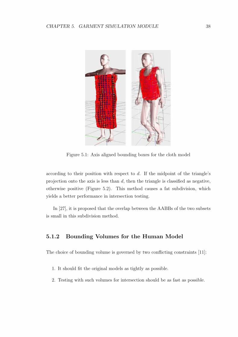
CHAPTER 5. GARMENT SIMULATION MODULE 38
Figure 5.1: Axis aligned bounding boxes for the cloth model
according to their position with respect to d. If the midpoint of the triangle’s
projection onto the axis is less than d, then the triangle is classified as negative,
otherwise positive (Figure 5.2). This method causes a fat subdivision, which
yields a better performance in intersection testing.
In [27], it is proposed that the overlap between the AABBs of the two subsets
is small in this subdivision method.
5.1.2 Bounding Volumes for the Human Model
The choice of bounding volume is governed by two conflicting constraints [11]:
1. It should fit the original models as tightly as possible.
2. Testing with such volumes for intersection should be as fast as possible.

CHAPTER 5. GARMENT SIMULATION MODULE 39
d mid min max
- +
Figure 5.2: Classification of geometrical primitives (reproduced from [27]).
AABBs and bounding spheres can be chosen with respect to the second con-
straint. However, for the long-thin oriented objects, since they cannot fit the ob-
ject tightly they are not preferred. OBBs and minimal ellipsoids provide tighter
fits, but the first constraint cannot be satisfied since intersection test is relatively
expensive by using them.
In our system, we used three different bounding volumes for the human model.
We compare the efficiencies of these volumes in collision detection in order to
choose the appropriate one.
The human body is segmented into different parts that correspond to the
bones of the human skeleton. Each part has attached a list of triangles that will
change their position with each movement of the bone. In all bounding volume
representations, the bounding volume of each body part is computed and they
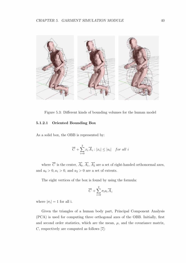
are used for describing the human body (Figure 5.3). We do not need to compute
the bounding volume hierarchy for the human model, since the number of body
parts is small.
CHAPTER 5. GARMENT SIMULATION MODULE 40
Figure 5.3: Different kinds of bounding volumes for the human model
5.1.2.1 Oriented Bounding Box
As a solid box, the OBB is represented by:
−→C +
2∑
i=0
xi−→A i : |xi| ≤ |ai| for all i
where−→C is the center,
−→A0,
−→A1,
−→A2 are a set of right-handed orthonormal axes,
and a0 > 0, a1 > 0, and a2 > 0 are a set of extents.
The eight vertices of the box is found by using the formula:
−→C +
2∑
i=0
σiai−→A i
where |σi| = 1 for all i.
Given the triangles of a human body part, Principal Component Analysis
(PCA) is used for computing three orthogonal axes of the OBB. Initially, first
and second order statistics, which are the mean, µ, and the covariance matrix,
C, respectively are computed as follows [7]:

CHAPTER 5. GARMENT SIMULATION MODULE 41
µ =1
3n
n∑
i=0
(pi + qi + ri),
Cjk =1
3n
n∑
i=0
(pijp
ik + qi
jqik + ri
jrik), 1 ≤ j, k ≤ 3
where the points pi, qi, and ri are the vertices of the ith triangle, n is the
number of triangles, pi = pi − µ, qi = qi − µ and ri = ri − µ.
Then, the eigenvectors of C, which are mutually orthogonal, are computed,
sorted in decreasing order and normalized. These eigenvectors are used as ba-
sis. Furthermore, the extremal vertices along each axis of this basis and the
dimensions of the bounding box, oriented with the basis vectors are found. The
dimension of the bounding box along an axis (eigenvector) is found by the extreme
values of the projection of the points on the corresponding axis.
5.1.2.2 Axis-Aligned Bounding Box
The axis aligned bounding box is the computationally simplest of all linear bound-
ing containers, and the one most frequently used in many applications. An axis-
aligned bounding box of a finite geometric object is a box that contains the object
and whose edges are parallel to the coordinate axes. It is defined by the maxi-
mum and minimum extents for all axes, (xmax, ymax, zmax) and (xmin, ymin, zmin),
respectively. The maximum and minimum extents are the maximum and mini-
mum coordinate values for the point set of the human body part’s vertices. These
values are easily computed in O(n) time with a single scan of all the vertex points.
5.1.2.3 Minimal Bounding Sphere
The bounding sphere of a geometric object is the smallest sphere containing the
object. It is described by a center point C and a radius R.

CHAPTER 5. GARMENT SIMULATION MODULE 42
There are several algorithms for computing the minimal sphere for a set of
points. In our study, we use the algorithm that is presented in [25]. The algorithm
avoids doing any recursion. It just scans the vertex list twice.
For a point set S, the algorithm is as follows:
1. 1st pass: The aim is to find an initial guess for the bounding sphere B.
Firstly, the points that has the maximum and minimum x, y, z values are
found, and three pairs of joints are obtained. Among these pairs, the pair
with the maximum point-to-point separation is selected and it is used as a
diameter. The center of this diameter is considered as the initial ball center.
2. 2nd pass: This pass is done for enlarging the sphere until all the points
are inside the sphere. For each point pk+1 , it is checked if it is inside the
bounding sphere Bk. If it is inside, then Bk+1 = Bk. Otherwise, expand Bk
just enough to include pk+1 (Figure 5.4).
B k
B k+1
p k+1
C k
C k+1
Figure 5.4: The minimal bounding sphere algorithm (2nd pass)
Each of the two stages of this algorithm does O(n) efficient computations. [25]
estimates that the sphere calculated is about 5% bigger than the ideal minimum-
radius sphere.

CHAPTER 5. GARMENT SIMULATION MODULE 43
5.1.3 Collision Detection between Bounding Volumes of
Human Model and Cloth Model
For detecting collisions between the skin layer of the human body and the cloth,
firstly an intersection test between each part of the body and the cloth is applied.
This is done by checking whether the bounding volume of the body part intersects
with the root of the cloth’s bounding volume hierarchy. If they overlap, the root’s
children are recursively checked and the AABB tree is traversed until the leaves
of the tree. The candidate pairs of triangles for geometry test are obtained by
checking whether the triangles of the leaf nodes intersect with the triangles of the
body part.
The intersection test between the two bounding volumes is the initial stage of
the collision test between the human model and the cloth model. For this pur-
pose, we need to compute the intersection between OBB-AABB, AABB-AABB
and bounding sphere-AABB. In this section, we will present the methods used
for collision detection between the bounding volumes (AABB, OBB, bounding
sphere).
5.1.3.1 OBB-AABB Intersection Test
In order to test the intersection between the OBB of the human body part and
the AABB of the cloth model, firstly we describe the AABB of the cloth as an
OBB and then we apply OBB-OBB collision detection test.
The “axial projection” algorithm based on projecting the bounding boxes
onto some axis in space can be used for testing the disjointness of two OBB. The
idea behind this algorithm is that if the segments, which are the projections of
bounding boxes in that axis, do not overlap, then the axis is called a “separating
axis” for the boxes and the boxes are disjoint. However, if there is an overlap
between segments, we cannot conclude that there is an overlap between two boxes.
We must do further tests.
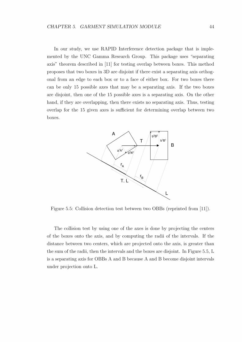
CHAPTER 5. GARMENT SIMULATION MODULE 44
In our study, we use RAPID Interference detection package that is imple-
mented by the UNC Gamma Research Group. This package uses “separating
axis” theorem described in [11] for testing overlap between boxes. This method
proposes that two boxes in 3D are disjoint if there exist a separating axis orthog-
onal from an edge to each box or to a face of either box. For two boxes there
can be only 15 possible axes that may be a separating axis. If the two boxes
are disjoint, then one of the 15 possible axes is a separating axis. On the other
hand, if they are overlapping, then there exists no separating axis. Thus, testing
overlap for the 15 given axes is sufficient for determining overlap between two
boxes.
A
B T
a 1 A
1
a 2 A
2
b 1 B 1
b 2 B
2
T. L
r A
r B
L
Figure 5.5: Collision detection test between two OBBs (reprinted from [11]).
The collision test by using one of the axes is done by projecting the centers
of the boxes onto the axis, and by computing the radii of the intervals. If the
distance between two centers, which are projected onto the axis, is greater than
the sum of the radii, then the intervals and the boxes are disjoint. In Figure 5.5, L
is a separating axis for OBBs A and B because A and B become disjoint intervals
under projection onto L.

CHAPTER 5. GARMENT SIMULATION MODULE 45
5.1.3.2 AABB-AABB Intersection Test
The disjointness of two boxes B1 and B2 can be tested by comparing their min-
imum and maximum extents in three dimensions. For instance, with respect to
the x-axis, we can check if either xmax1 < xmin2 or xmax2 < xmin1 is true. If it is,
then we conclude that B1 and B2 are disjoint. If it is not, we apply disjointness
tests with respect to the y-axis and z-axis. If any of the tests is true, then B1
and B2 are disjoint. If all of them are false, then the two boxes are intersecting.
5.1.3.3 Bounding Sphere-AABB Intersection Test
Center of sphere-minimum extent of AABB distance and center of sphere-
maximum extent of AABB distance are used for detecting whether the bounding
sphere intersects with the AABB. If one of the distances is less than the radius
of the sphere, then we conclude that there is an overlap.
5.1.3.4 Comparison of bounding volumes
It is difficult to do a general analysis of the performance of collision detection
algorithm because performance is situation specific. We compare the bounding
volumes for the same motion behavior and same garment pattern. The results of
this simulation are presented in Chapter 6.
5.1.4 Geometrical Collision Detection
After detecting bounding volume interferences, the geometrical collision detection
tests are applied between the triangles in the intersecting bounding volumes.
Collision of two triangles may be in one of the two ways:
1. Vertex-triangle collision: a vertex of one triangle may collide with the other
triangle.
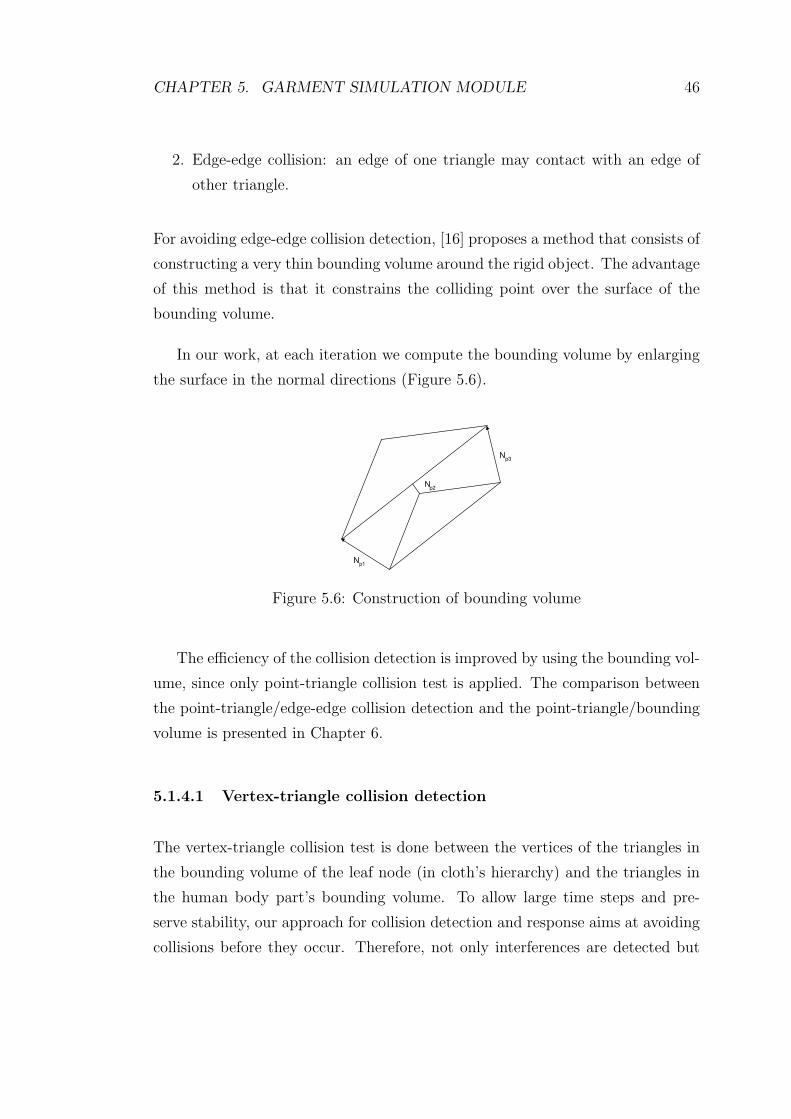
CHAPTER 5. GARMENT SIMULATION MODULE 46
2. Edge-edge collision: an edge of one triangle may contact with an edge of
other triangle.
For avoiding edge-edge collision detection, [16] proposes a method that consists of
constructing a very thin bounding volume around the rigid object. The advantage
of this method is that it constrains the colliding point over the surface of the
bounding volume.
In our work, at each iteration we compute the bounding volume by enlarging
the surface in the normal directions (Figure 5.6).
N p2
N p1
N p3
Figure 5.6: Construction of bounding volume
The efficiency of the collision detection is improved by using the bounding vol-
ume, since only point-triangle collision test is applied. The comparison between
the point-triangle/edge-edge collision detection and the point-triangle/bounding
volume is presented in Chapter 6.
5.1.4.1 Vertex-triangle collision detection
The vertex-triangle collision test is done between the vertices of the triangles in
the bounding volume of the leaf node (in cloth’s hierarchy) and the triangles in
the human body part’s bounding volume. To allow large time steps and pre-
serve stability, our approach for collision detection and response aims at avoiding
collisions before they occur. Therefore, not only interferences are detected but

CHAPTER 5. GARMENT SIMULATION MODULE 47
also proximities. The vertex-triangle pairs that are found as colliding or close are
stored in a data structure and they are used in the collision response.
The interference detection is achieved by finding whether the particle is in the
positive side (above), negative side (below) or on the plane of the triangle. The
position of particle with respect to the triangle is found by using the equation
of the triangle plane, which divides the space in three subspaces: (1) positive
half-space, (2) negative half-space, (3) space that contains all the points lying on
the plane. Suppose (x,y,z) is the coordinate of the particle and the equation of
the plane is ax+by+cz+d=0 where a,b,c,d are known. The relationship between
the plane and the particle is determined using the plane equation as follows:
If ax + by + cz + d > 0, then the point is in the positive half-space.
If ax + by + cz + d = 0, then the point lies on the plane.
If ax + by + cz + d < 0, then the point is in the negative half-space.
If the particle is in the positive side at time t and in the negative side at time
t + ∆t, it can be concluded that interference has occurred during the time step
∆t. Thus, the particle-triangle pair must be stored as a collision pair.
The proximity detection is applied if the particle is in the positive side of the
collision plane in both t and t + ∆t. The algorithm first computes the distance
between the point P0 = (x0, y0, z0) and the triangle plane Π : ax+ by + cz +d = 0
by using the following formula:
d(P0) = |P0 − V0|cosΘ =n · (P0 − V0)
|n| =ax0 + by0 + cz0 + d√
a2 + b2 + c2
This formula makes use of the dot product to get the projection of the vector
(P0 − V0) onto n, where V0 is the vertex of the triangle and n is the normal
vector of the triangle. The distance that is obtained is a signed distance, which
is positive on one side of the plane and negative on the other. So, we take the
absolute value of it to get an absolute distance.
If the distance is less than a threshold, then the projection of point on the
CHAPTER 5. GARMENT SIMULATION MODULE 48
triangle is found and it is determined whether the projected point is inside the
triangle. This is done by using the angles. In this approach, we firstly construct 3
vectors (vec1, vec2, vec3) from the projection point to each vertex of the triangle.
Then, we normalize them. We compute the angles between the vectors vec1 and
vec2, vec1 and vec3, vec2 and vec3 and we check whether the sum of the angles
is 360 degrees (or 2Π in radians). If the sum is nearly 360 degrees, we concluded
that the vertex is inside the triangle and we store the particle-triangle pair as a
candidate collision.
5.1.4.2 Edge-edge collision detection
In order to check the proximity between two edges, S1 and S2, we find the pair
of points, one on each edge, that are closest to each other and check the distance
between them. We use the algorithm in the web page
http : //softsurfer.com/Archive/algorithm 0106/algorithm 0106.htm.
In this algorithm, the edge S1 (between endpoints P0 and P1) is represented
as the points on L1 : P (s) = P0 + s ∗ (P1 − P0) = P0 + s ∗ u with 0 ≤ s ≤ 1.
Similarly, the edge S2 (between endpoints Q0 and Q1) is given by the points
Q(t) with 0 ≤ t ≤ 1. For the computation of the closest points firstly sc and tc
for L1 and L2 are computed. If they are in the range of the involved segment,
then it is concluded that they are also the closest points for L1 and L2. But
if they lie outside the range, then they are not and new points that minimize
w(s, t) = P (s) − Q(t) over the ranges of interest are determined. The details of
this algorithm are presented in the web page.
5.2 Self-Collision Detection
In our study, we use the AABB hierarchy for the cloth model in order to im-
prove the self-collision detection test. We traverse the hierarchy and we test the
intersection of two polygons only if their bounding volumes intersect.
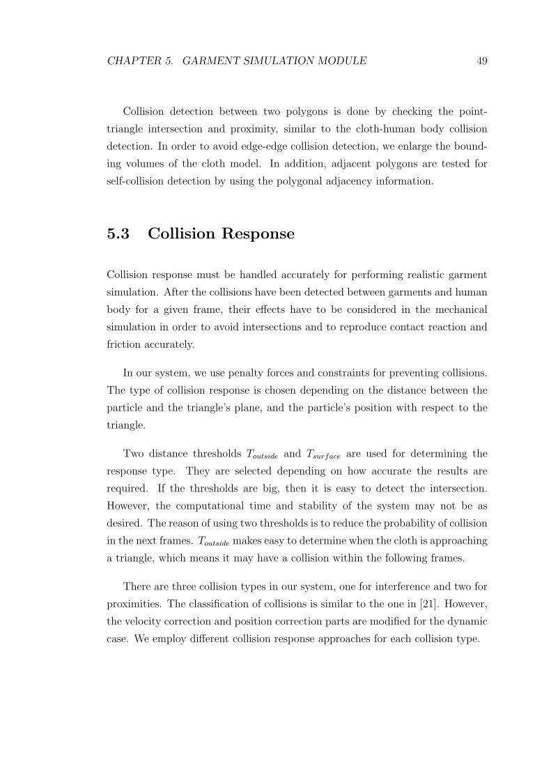
CHAPTER 5. GARMENT SIMULATION MODULE 49
Collision detection between two polygons is done by checking the point-
triangle intersection and proximity, similar to the cloth-human body collision
detection. In order to avoid edge-edge collision detection, we enlarge the bound-
ing volumes of the cloth model. In addition, adjacent polygons are tested for
self-collision detection by using the polygonal adjacency information.
5.3 Collision Response
Collision response must be handled accurately for performing realistic garment
simulation. After the collisions have been detected between garments and human
body for a given frame, their effects have to be considered in the mechanical
simulation in order to avoid intersections and to reproduce contact reaction and
friction accurately.
In our system, we use penalty forces and constraints for preventing collisions.
The type of collision response is chosen depending on the distance between the
particle and the triangle’s plane, and the particle’s position with respect to the
triangle.
Two distance thresholds Toutside and Tsurface are used for determining the
response type. They are selected depending on how accurate the results are
required. If the thresholds are big, then it is easy to detect the intersection.
However, the computational time and stability of the system may not be as
desired. The reason of using two thresholds is to reduce the probability of collision
in the next frames. Toutside makes easy to determine when the cloth is approaching
a triangle, which means it may have a collision within the following frames.
There are three collision types in our system, one for interference and two for
proximities. The classification of collisions is similar to the one in [21]. However,
the velocity correction and position correction parts are modified for the dynamic
case. We employ different collision response approaches for each collision type.

CHAPTER 5. GARMENT SIMULATION MODULE 50
5.3.1 Case 0: No intersection
If the distance between the point and the triangle is greater than Toutside, then
no response is applied (Figure 5.7).
Particle
Projection of
Particle
T outside
T surface
a
Normal
Figure 5.7: Collision Response: Case 0
5.3.2 Case 1: Point-Triangle Proximity
If the distance is between Toutside and Tsurface, a penalty force for decreasing the
probability of collision in the following frames is applied (Figure 5.8). The penalty
force is computed by using the Newton’s Law−→F = m−→a . The magnitude of the
acceleration is proportional to the negated distance between the vertex and the
surface. The acceleration is applied in the direction of the closest point pair of the
close faces, contrary to the earlier approaches [24, 21], which use normal direction
of the triangle as the direction of acceleration.
The penalty force is added to the total force applied to the vertex due to
gravity, wind, etc.. It avoids intersection with the human body by modifying the
direction of the movement for the following frames.

CHAPTER 5. GARMENT SIMULATION MODULE 51
Particle
Projection of
Particle
T outside
T surface
a
Normal
Figure 5.8: Collision Response: Case 1
5.3.3 Case 2: Point-Triangle Intersection
For the second case, where the distance is less than Tsurface, in order to make
the collision response smoother, both penalty forces and velocity correction are
applied for the colliding particle on the cloth (Figure 5.9).
Particle
Projection of
Particle
T outside
T surface a
Normal
Figure 5.9: Collision Response: Case 2
The velocity correction scheme is similar to the method in [28]. However,
we have to do some adjustments for the computation of the object velocity and
response direction.

CHAPTER 5. GARMENT SIMULATION MODULE 52
Computation of Vhuman is done by using the barycentric coordinates (Fig-
ure 5.10). Barycentric coordinates are local coordinate systems that are defined
with respect to a set of points in three-dimensional space. They can be used for
testing whether a point is in triangle. Furthermore, they are generally utilized
for interpolating any quantity, such as color, normal, and texture coordinate. For
finding Vhuman, firstly we compute the barycentric coordinates by using the ver-
tices of the triangle and the particle of the cloth. Then, by using the barycentric
coordinates, the velocity of the triangle is interpolated as an affine combination
of triangle vertices’ velocities.
V 1
V 0
V 2
a 1
a 2
a 3
Figure 5.10: Interpolation of velocities using barycentric coordinates
The direction between the cloth particle and the closest point to it on the
human triangle is used as the response direction (Figure 5.11). This leads to a
more stable collision response, since there are no discontinuities in the constrained
direction [19].
Figure 5.11: Response direction for different particles (Reprinted from [19])
The velocity of the particle after collision response is modified by using the

CHAPTER 5. GARMENT SIMULATION MODULE 53
formula:
Vres = CfricVt − CreflVn + ΠVhuman
where Cfric and Crefl are friction and reflection coefficients, Π is the projection
onto the response direction, Vt and Vn are the tangent and normal components
of relative velocity between the cloth and the human body (Figure 5.12). The
relative velocity is found by subtracting Vhuman from the velocity of the particle.
particle
p
V human
V n
V t
V relative
Figure 5.12: Resolving collisions by manipulating velocities
Since the velocity modification does not always produce satisfactory results,
we also apply forces. The computation of the penalty forces is same as the one
in case 1.
5.3.4 Case 3: Point-Triangle Interference
In this case, the point is in the back of the triangle. This means an intersec-
tion has occurred. So, we apply position correction and velocity modification
(Figure 5.13).
Velocities are adjusted according to the approach mentioned in the case 2.
The position correction is done by changing the position of the particle in the
next frame. The new position of the particle becomes

CHAPTER 5. GARMENT SIMULATION MODULE 54
Particle
T outside
T surface
a
Normal
Figure 5.13: Collision Response: Case 3
P = p + Nr
where p is the projection of particle on the triangle and Nr is the response di-
rection. Response direction is the direction of the closest point pair of the close
faces.

Chapter 6
Results
6.1 Visual Results
In order to demonstrate the visual results of our system, we show a series of still
images taken from various animations.
In the animation sequences, from Figure 6.1 to Figure 6.6, the human body
wearing different garments animated with various motion behaviors. For example,
in Figure 6.1, the human body is raising his leg and he has a dress on it. Figure 6.5
demonstrates a human body wearing a t-shirt and a shirt. He is turning right,
then left.
The visual results in Figure 6.7 show the different rendering modes in the
system. In these images, the human model has different postures and has different
clothes on it.
In Figure 6.8, we show the results of falling clothes. In these frames, the
clothes are falling on the human body due to the gravity. It can be seen more
clear in these images that there is no interference. In addition, we show the
results when the cloth is hanging from the two points and the human body is
animated using the “walking” behavior in Figure 6.9. In this sequence, the cloth
55
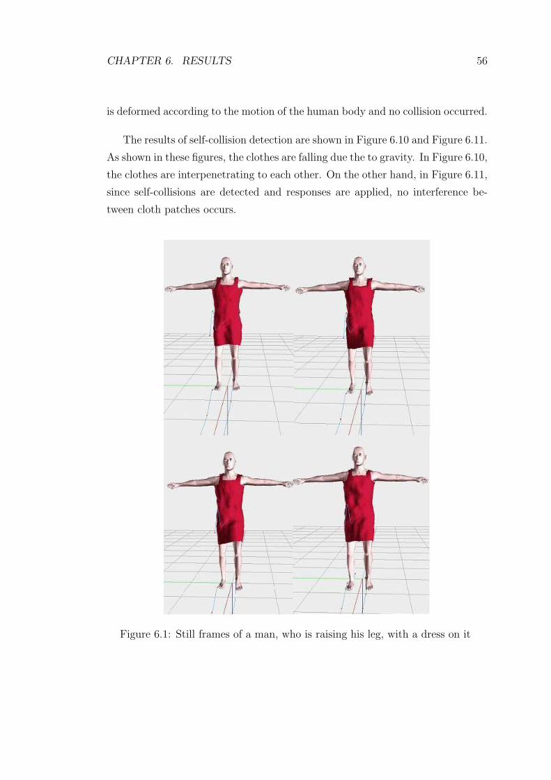
CHAPTER 6. RESULTS 56
is deformed according to the motion of the human body and no collision occurred.
The results of self-collision detection are shown in Figure 6.10 and Figure 6.11.
As shown in these figures, the clothes are falling due the to gravity. In Figure 6.10,
the clothes are interpenetrating to each other. On the other hand, in Figure 6.11,
since self-collisions are detected and responses are applied, no interference be-
tween cloth patches occurs.
Figure 6.1: Still frames of a man, who is raising his leg, with a dress on it
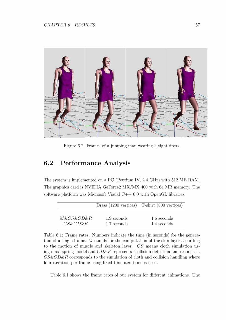
CHAPTER 6. RESULTS 57
Figure 6.2: Frames of a jumping man wearing a tight dress
6.2 Performance Analysis
The system is implemented on a PC (Pentium IV, 2.4 GHz) with 512 MB RAM.
The graphics card is NVIDIA GeForce2 MX/MX 400 with 64 MB memory. The
software platform was Microsoft Visual C++ 6.0 with OpenGL libraries.
Dress (1200 vertices) T-shirt (800 vertices)
M&CS&CD&R 1.9 seconds 1.6 secondsCS&CD&R 1.7 seconds 1.4 seconds
Table 6.1: Frame rates. Numbers indicate the time (in seconds) for the genera-tion of a single frame. M stands for the computation of the skin layer accordingto the motion of muscle and skeleton layer. CS means cloth simulation us-ing mass-spring model and CD&R represents “collision detection and response”.CS&CD&R corresponds to the simulation of cloth and collision handling wherefour iteration per frame using fixed time iterations is used.
Table 6.1 shows the frame rates of our system for different animations. The

CHAPTER 6. RESULTS 58
Figure 6.3: Frames of a man wearing t-shirt and shirt, and wearing dress
human model has 5,133 vertices.
6.2.1 Comparison of Collision Detection Approaches
For comparing the computational efficiency of point-triangle/edge-edge (PT EE)
collision detection test with point-triangle/bounding volume (PT BV) test, a
cloth mesh with size 20 x 20 is positioned in front of the human model. Then,
the human model is animated using the behavior “walking2”, and the results
shown in (Figure 6.12) are obtained. The times shown include the rendering and
animation of the cloth. According to (Figure 6.12), it can be concluded that the
PT BV is much more efficient than the PT EE, since it only needs computation
of bounding volume at each iteration.
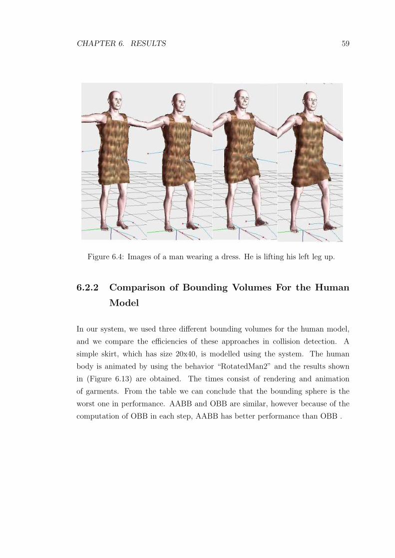
CHAPTER 6. RESULTS 59
Figure 6.4: Images of a man wearing a dress. He is lifting his left leg up.
6.2.2 Comparison of Bounding Volumes For the Human
Model
In our system, we used three different bounding volumes for the human model,
and we compare the efficiencies of these approaches in collision detection. A
simple skirt, which has size 20x40, is modelled using the system. The human
body is animated by using the behavior “RotatedMan2” and the results shown
in (Figure 6.13) are obtained. The times consist of rendering and animation
of garments. From the table we can conclude that the bounding sphere is the
worst one in performance. AABB and OBB are similar, however because of the
computation of OBB in each step, AABB has better performance than OBB .
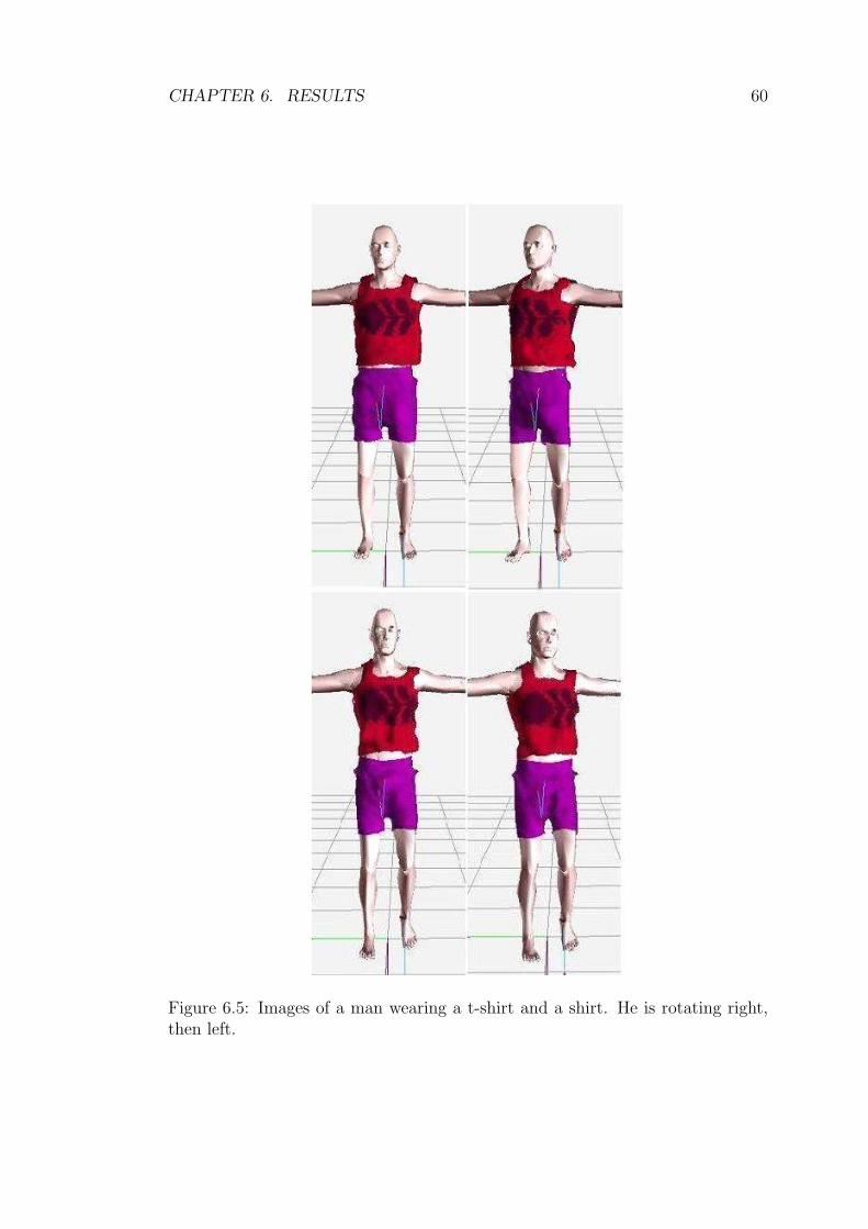
CHAPTER 6. RESULTS 60
Figure 6.5: Images of a man wearing a t-shirt and a shirt. He is rotating right,then left.

CHAPTER 6. RESULTS 61
Figure 6.6: Frames from different animations
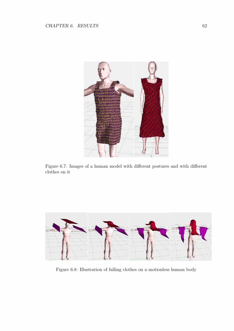
CHAPTER 6. RESULTS 62
Figure 6.7: Images of a human model with different postures and with differentclothes on it
Figure 6.8: Illustration of falling clothes on a motionless human body
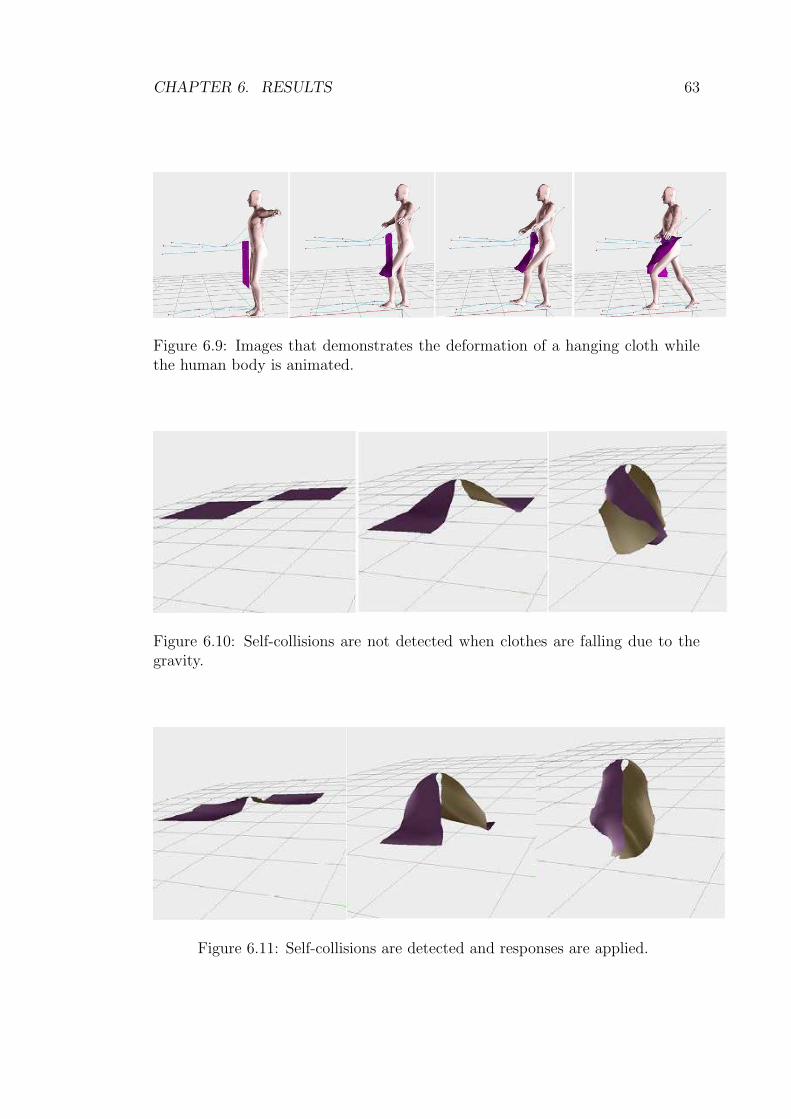
CHAPTER 6. RESULTS 63
Figure 6.9: Images that demonstrates the deformation of a hanging cloth whilethe human body is animated.
Figure 6.10: Self-collisions are not detected when clothes are falling due to thegravity.
Figure 6.11: Self-collisions are detected and responses are applied.

CHAPTER 6. RESULTS 64
Comparison of PT_EE and PT_BV Methods
0
0.02
0.04
0.06
0.08
0.1
0.12
0.14
0.16
0
5
10
15
20
25
30
35
40
45
50
55
60
65
70
75
80
85
90
95
100
105
110
115
Frame Number
Tim
e (
in s
eco
nd
s)
PT_EE
PT_BV
Figure 6.12: Comparison of point-triangle/edge-edge (PT EE) collision detectionwith point-triangle/bounding volume (PT BV)
Comparison of OBB, AABB and Bounding Sphere Methods
0.4
0.5
0.6
0.7
0.8
0.9
1
1.1
0
3
6
9
12
15
18
21
24
27
30
33
36
39
42
45
48
Frame Number
Tim
e (
in s
eco
nd
s)
OBB
AABB
BS
Figure 6.13: Comparison of OBB, AABB and Bounding Sphere approaches forthe human model

Chapter 7
Conclusion
In the last decade, there is an increasing demand for the garment design and
simulation systems in order to obtain realistic virtual humans who are wearing
garments on them.
In this thesis, a system that can be used both by the garment based e-
commerce applications and textile industry is presented. The system enables
the simulation of a dressed character with different motion behaviors. Several
issues such as bounding volumes, collision detection and collision response have
been worked on and investigated in detail.
The process in the system can be summarized as the design of motion be-
haviors, design of garment patterns, fitting the garments onto the human body
and animation of human body, which has garments on it. In the system, motion
behaviors are designed by using the tools that are implemented by [18]. In ad-
dition, the garment design tools enables the designer with an effective tool for
creating 3D garments from their 2D panels through cutting and seaming. There
exist an option for modifying the rendering models, such as knitwear, woven and
velvet. This enables the designer to visualize the garments in different modes and
increases his/her creativity.
We mainly focus on the animation of garments due to the motion of human
65
CHAPTER 7. CONCLUSION 66
body. This task consist of dealing with the deformation of cloth, collision de-
tection and collision response. We use mass-spring model for the cloth since it
is a simple and efficient cloth model. As an integration method, explicit Euler’s
method is preferred although it needs small time intervals for obtaining stable
animations. The reason of using Euler’s method is that it is easy to implement
and fast to execute.
Collision detection is the most time consuming part of a garment simulation
system. Thus, we make use of bounding volumes for both cloth and human mod-
els. We use axis aligned bounding box hierarchy for the cloth model. In addition,
for the human model we use different bounding volumes, such as oriented bound-
ing boxes (OBB), axis aligned bounding boxes (AABB) and bounding spheres,
and we compare their efficiencies. From the computational time of the methods
for the same motion sequences, we concluded that bounding sphere is the worst
one.
The geometrical collision detection in our system is done by applying point-
triangle collision detection. We avoid using edge-edge collision detection by com-
puting the bounding volume around the human body at each step. We apply the
collision detection between the enlarged human body and the cloth model. Thus,
the computational time for the collision detection is reduced.
Collision response approach used in the system is a combination of both
penalty forces and constraints. We classify the collisions into three depending
on the position of the cloth particle with respect to the human body. We apply
different responses for each collision type. The reason of this approach is to avoid
collisions before they occur and to correct interferences after they occur.
More research is to be done regarding the improvement of collision handling
in dressing virtual humans. These can be summarized as follows:
• Usage of different bounding volumes, such as k-Dops, for the human model.
• Classification of cloth into types and applying collision handling depending
on the cloth type.

CHAPTER 7. CONCLUSION 67
• Self-collision detection between different garment layers.
• Usage of space subdivision for the cloth and human models.
• Representing human model by bounding ellipsoids, and detecting particle-
ellipsoid collisions.

Bibliography
[1] D. Baraff and A. Witkin. Large steps in cloth simulation. In SIGGRAPH
98 Conference Proceedings, Annual Conference Series, pages 43–54. Addison
Wesley, 1998.
[2] D. Breen, D. House, and P. Getto. A physical-based particle model of woven
cloth. Visual Computer, pages 264–277, 1992.
[3] R. Bridson, R. Fedkiw, and J. Anderson. Robust treatment of collisions,
contact, and friction for cloth animation. In Computer Graphics (Proc. SIG-
GRAPH), pages 594–603, 2002.
[4] F. Cordier and N. Magnenat-Thalmann. Real-time animation of dressed vir-
tual humans. In Eurographics Conference Proceedings. Blackwell Publishers,
2002.
[5] F. Cordier, H. Seo, and N. Magnenat-Thalmann. Made-to-measure technolo-
gies for online clothing store. IEEE Computer Graphics and Applications,
pages 38–48, 2003.
[6] U. Cugini and C. Rizzi. 3D design and simulation of men garments. In in
Proceeding Workshop WSCG 2002, 2002.
[7] R. O. Duda and P. E. Hart. Pattern Classification and Scene Analysis. John
Wiley and Sons, 1973.
[8] F. Durupinar. A 3D garment design and simulation system. MS.Thesis,
Bilkent University, Department of Computer Engineering and Information
Science, 2004.
68

BIBLIOGRAPHY 69
[9] B. Eberhardt, A. Weber, and W. Strasser. A fast flexible particle-system
model for cloth draping. IEEE Computer Graphics and Applications (special
issue Computer Graphics in Textiles and Apparel), pages 52–59, 1996.
[10] J. W. Eischen, S. Deng, and T. G. Clapp. Finite-element modeling and con-
trol of flexible fabric parts. IEEE Computer Graphics and Applications (spe-
cial issue Computer Graphics in Textiles and Apparel), pages 71–80, 1996.
[11] S. Gottschalk and a. M. D. Lin, M. Obb-tree: A hierarchical structure for
rapid interference detection. In Computer Graphics (Proc. SIGGRAPH),
pages 171–180, 1996.
[12] C. Gross, A. Fuhrmann, V. Luckas, and J. Encarnacao. Virtual try-on:
Topics in realistic, individualized dressing in virtual reality. In Proceedings
of the Virtual and Augmented Reality Status Conference, 2004.
[13] S. Huh, D. N. Metaxas, and N. I. Badler. Collision resolutions in cloth
simulation. In IEEE Computer Animation, pages 122–127, 2001.
[14] J. T. Klosowski, M. Held, J. S. B. Mitchell, H. Sowizral, and K. Zikan.
Efficient collision detection using bounding volume hierarchies of k-dops.
IEEE Transactions on Visualization and Computer Graphics, 6:21–36, 1998.
[15] M. Lin and S. Gottschalk. Collision detection between geometric models:
A survey. In Proc. of IMA Conf. on Mathematics of Surfaces, pages 37–56,
1998.
[16] J. Liu, M. Ko, and R. Chang. Collision avoidance in cloth animation. The
Visual Computer, 12:234–243, 1996.
[17] J. D. Liu, M. T. Ko, and R. C. Chang. A simple self-collision avoidance for
cloth animation. Computers & Graphics, 22(1):117–128, 1998.
[18] A. Memisoglu. Human motion control using inverse kinematics. MS.Thesis,
Bilkent University, Department of Computer Engineering and Information
Science, 2003.

BIBLIOGRAPHY 70
[19] J. Mezger, S. Kimmerle, and O. Etzmu. Improved collision detection and
response techniques for cloth animation. In Technical Report,Universitat
Tubingen, 2002.
[20] N. H. Ng and R. L. Grimsdale. Computer graphics techniques for modelling
cloth. IEEE Computer Graphics and Applications, 16:28–41, 1996.
[21] N. Pelechano. Real-time collision detection between cloth and skinned
avatars using obb. Master Thesis at UCL (University College London), 2002.
[22] D. Protopsaltou, C. Luible, M. Arevalo, and N. Magnenat-Thalmann. A
body and garment creation method for an internet based virtual fitting room.
In Computer Graphics International Conference Proceedings, pages 105–122.
Springer Verlag, 2002.
[23] X. Provot. Deformation constraints in a mass-spring model to describe rigid
cloth behaviour. In Proceedings of Graphics Interface, pages 141–155, Que-
bec, Canada, 1995.
[24] X. Provot. Collision and self-collision detection handling in cloth model
dedicated to design garments. In Proceedings of Graphics Interface, pages
177–189, 1997.
[25] J. Ritter. An Efficient Bounding Sphere. Graphics Gems, Academic Press
Professional, Inc., San Diego, CA, 1990.
[26] I. Rudomin and J. L. Castillo. Realtime clothing: geometry and physics. In
In WSCG’2002 Posters, University of West Bohemia, Plzen, Czech Republic,
pages 45–48, 2002.
[27] G. Van Den Bergen. Efficient collision detection of complex deformable
models using aabb trees. Journal of Graphics Tools, 2(4):1–13, 1997.
[28] T. Vassilev, B. Spanlang, and Y. Chrysanthou. Fast cloth animation on
walking avatars. In Proceedings of the Eurographics, volume 20. Blackwell
Publishers, 2001.
BIBLIOGRAPHY 71
[29] P. Volino, M. Courchesne, and N. Magnenat-Thalmann. Versatile and ef-
ficient techniques for simulating cloth and other deformable objects. In
SIGGRAPH 95 Conference Proceedings, Annual Conference Series, pages
137–144, 1995.
[30] P. Volino and N. Magnenat-Thalmann. Efficient self-collision detection on
smoothly discretized surface animations using geometrical shape regular-
ity. In Proceedings Eurographics ’94, Computer Graphics Forum, volume 13,
pages 155–166, 1994.
[31] P. Volino and N. Magnenat-Thalmann. Implementing fast cloth simulation
with collision response. In Computer Graphics International, pages 257–268,
Geneva, Switzerland, 2000.
[32] P. Volino and N. Magnenat-Thalmann. Virtual Clothing. Springer-Verlag,
2000.
[33] P. Volino and N. Magnenat-Thalmann. Comparing efficiency of integration
methods for cloth animation. In Proceedings of Computer Graphics Interna-
tional (CGI), pages 265–274, Hong-Kong, 2001.
[34] C. C. L. Wang, Y. Wang, and M. M. F. Yuen. Feature based 3D garment
design through 2d sketches. Computer-Aided Design, 35(7):659–672, 2003.
[35] Y. Yang, N. Magnenat-Thalmann, and D. Thalmann. 3D garment design
and animation – a new design tool for the garment industry. Computers in
Industry, 19:185–191, 1992.
[36] M. S. Yesil. Realistic rendering of a multi-layered human body model.
MS.Thesis, Bilkent University, Department of Computer Engineering and
Information Science, 2003.
[37] D. Zhang and M. Yuen. Collision detection for clothed human animation.
In Proceedings Pacific Graphics, pages 328–337, 2000.
Appendix A
The System At Work
In this part we introduce the user interface and functionality of our system. The
whole system is implemented by Aydemir Memisoglu, Mehmet Sahin Yesil,Ilknur
Kaynar and Funda Durupınar.
Motion control part is implemented by Aydemir Memisoglu using inverse kine-
matics based on analytical methods. Realistic rendering using a multi-layered hu-
man model that consists of skeleton, muscles and skin is implemented by Mehmet
Sahin Yesil. The garment design and rendering part is implemented by Funda
Durupınar. This part includes different rendering modes, such as knitwear and
woven. Finally, garment simulation part including cloth deformation and collision
handling is implemented by Ilknur Kaynar Kabul.
A.1 Overview
Our application is Single Document Interface (SDI) application implemented us-
ing Visual C++ 6.0 and Microsoft Foundation Classes (MFC). The graphics
display API OpenGL is used. The top level user interface of the system is seen
in (Figure A.1). The elements on the interface can be mainly divided into five
parts:
72

APPENDIX A. THE SYSTEM AT WORK 73
1. The Main Menu: This consists of menu bar and toolbar. It basically allows
the user to control the application.
2. The Motion Control, Skinning, Garment Design and Simulation Toolbox:
This toolbox allows user to control the skeleton, generate new motions, and
model the skin mesh. In addition, it provides the user to create garments
and to simulate them on the human body. It consists of six panels: Skele-
ton, Motion, Skinning, Garment Design, Cloth Simulation Parameters and
Collision Handling.
3. The Keyframe Editor: This editor allows the user to generate curves for
distance, joint angles in order to characterize the motion of the articulated
Figure [18].
4. The Garment Design Editor: This editor permits the user to create garment
patterns, to cut them and to select particles for seaming.
5. The Viewing Area: The viewing area has quad view layout with the front,
top, side, and perspective views of the 3D environment.
A.2 The Main Menu
The main menu part of the program consists of the menu bar and the other tool-
bars. The menu bar includes “File”, “View”, “Motion”, “Snapshot” and “Help”
subitems and provides the general functionalities like creating and opening an
object model, changing the user interface options, and creating a new motion or
loading an existing one. The user also can start, stop, pause and step by step
play the loaded animation by using the toolbar. The “Snapshot” menu item and
the toolbar gives user the opportunity to take the snapshots of the animation.
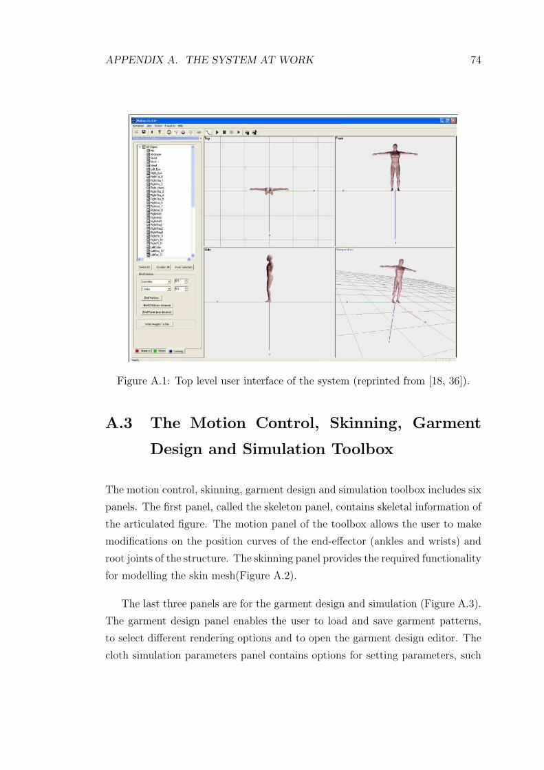
APPENDIX A. THE SYSTEM AT WORK 74
Figure A.1: Top level user interface of the system (reprinted from [18, 36]).
A.3 The Motion Control, Skinning, Garment
Design and Simulation Toolbox
The motion control, skinning, garment design and simulation toolbox includes six
panels. The first panel, called the skeleton panel, contains skeletal information of
the articulated figure. The motion panel of the toolbox allows the user to make
modifications on the position curves of the end-effector (ankles and wrists) and
root joints of the structure. The skinning panel provides the required functionality
for modelling the skin mesh(Figure A.2).
The last three panels are for the garment design and simulation (Figure A.3).
The garment design panel enables the user to load and save garment patterns,
to select different rendering options and to open the garment design editor. The
cloth simulation parameters panel contains options for setting parameters, such

APPENDIX A. THE SYSTEM AT WORK 75
Figure A.2: The motion control and the skinning toolbox (reproduced from [36])
as damping, gravity, wind and time intervals. Lastly, collision handling panel
provides selection of bounding volumes for cloth and human body, and setting of
collision detection and response parameters.
A.4 The Keyframe Editor
The keyframe editor toolbox will be displayed for a selected joint when one of the
controlled joints is double-clicked. While the motion panel includes the controls
for manipulating the position curve of a joint, the keyframe editor provides the
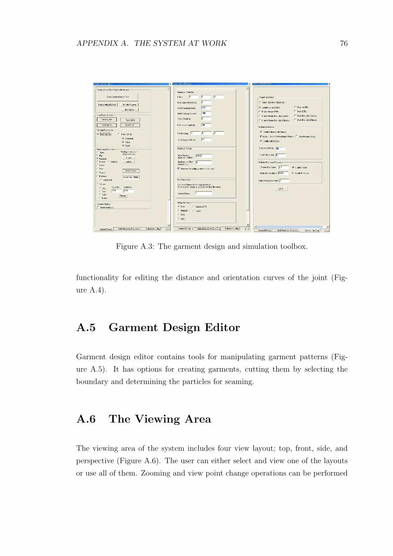
APPENDIX A. THE SYSTEM AT WORK 76
Figure A.3: The garment design and simulation toolbox.
functionality for editing the distance and orientation curves of the joint (Fig-
ure A.4).
A.5 Garment Design Editor
Garment design editor contains tools for manipulating garment patterns (Fig-
ure A.5). It has options for creating garments, cutting them by selecting the
boundary and determining the particles for seaming.
A.6 The Viewing Area
The viewing area of the system includes four view layout; top, front, side, and
perspective (Figure A.6). The user can either select and view one of the layouts
or use all of them. Zooming and view point change operations can be performed

APPENDIX A. THE SYSTEM AT WORK 77
Figure A.4: The keyframe editor
Figure A.5: The garment design editor
in each frame by using mouse and keyboard keys. Using left mouse button and
holding the ctrl key, the user can rotate the Figure in 3D space. The Figure can
be translated using the right mouse button and holding the ctrl key. Zooming
can be done using just the right mouse button.

APPENDIX A. THE SYSTEM AT WORK 78
Figure A.6: The viewing area