animated hand gestures - free university of...
TRANSCRIPT
Animated Hand Gesturesfor Italian Sign Language
Master Thesis of the Faculty of Computer Science
written by
Jieyun Ren
FUB supervisor: Dr Rosella Gennari
Submitted to: the Board of Examiners for the
European Master of Science in Computational Logic
at the Free University of Bozen-Bolzano.
Date of the public defense: Academic Year:
October 27, 2006 2005/2006


E-LISAcknowledgements
I wish to express my gratitude to everyone who contributed to the realization of this thesis.
I must single out my excellent supervisor, Dr. Rosella Gennari from the Free University of
Bozen-Bolzano, who supported it during the months it took to bring it to fruition.
I also want to thank Dott. Paolo Dongilli, Dr. Pablo Filottrani, Prof. Enrico Franconi, Dr. Raffaella
Bernardi, Dr. Sergio Tessaris all from the Free University of Bozen-Bolzano, for their expert
advice and creating a wonderful work atmosphere.
I am also grateful to the e-LIS project members from the European Academy of Bozen-Bolzano,
Dott. Claudio Zanoni and Dr. Chiara Vettori, for their help in providing research material related to
e-LIS.
I am also grateful to my parents who support me always.
This thesis is dedicated to Ren Xinchang.
Jieyun Ren October, 2006
iii

E-LIS
iv

E-LISTable of Contents Acknowledgements........................................................................................................................... iii
Table of Contents................................................................................................................................v
List of Illustrations.......................................................................................................................... viii
Abstract..............................................................................................................................................xi
Chapter 1. Introduction.......................................................................................................................1
1.1. Thesis rationale........................................................................................................................1
1.2. Who can benefit from this thesis............................................................................................. 1
1.3. Thesis structure........................................................................................................................1
Chapter 2. LIS Signs...........................................................................................................................3
2.1. Background on LIS movements.............................................................................................. 3
2.2. Background on the e-LIS project.............................................................................................3
2.3. Our role in the e-LIS project....................................................................................................3
Chapter 3. Animation Editors...........................................................................................................5
3.1. Introduction............................................................................................................................. 5
3.2. Introduction to H-Animator, Maya, SVG animation editors...................................................5
3.2.1. Introduction to H-Animator .............................................................................................5
3.2.2. Introduction to Maya....................................................................................................... 5
3.2.3. Introduction to SVG animation editors............................................................................ 6
3.2.3.1. What is SVG?............................................................................................................ 6
3.2.3.2. SVG Syntax............................................................................................................... 6
3.2.3.3. The chosen SVG animator ........................................................................................7
3.3. Assessment of the tested animation editors ............................................................................7
3.3.1. The case of H-Animator................................................................................................... 7
3.3.2. The case of Maya..............................................................................................................8
3.3.3. The case of SVG animators..............................................................................................8
Chapter 4. Animated LIS hand gestures............................................................................................9
4.1. Introduction............................................................................................................................. 9
4.2. H-Animator..............................................................................................................................9
4.3. Implementing hand gestures with SVG animation editors ..................................................10
4.3.1. Making the linear movements with Sketsa and Ikivo Animator.................................... 10
4.3.1.1. Arrow movements................................................................................................... 11
4.3.1.2. Arrow movements with the cube.............................................................................12
4.3.2. Circular movements........................................................................................................13
4.4. Implement hand gestures with Maya.....................................................................................16
v
E-LIS 4.4.1. Basic hand shapes...........................................................................................................16
4.4.2. Make the hand movement...............................................................................................17
4.4.3. Finger moving animation................................................................................................19
4.4.4. Finger bending................................................................................................................21
4.4.4.1. Drawing the finger model........................................................................................21
4.4.4.2. Creating a skeleton hierarchy.................................................................................. 21
4.4.4.3.Parenting the finger model into the skeleton............................................................22
4.4.4.4. Applying IK to the finger skeleton hierarchy..........................................................22
4.4.4.5. Constrain the range of the fingertip's movement....................................................23
4.4.4.6. Constrain the range of the finger's rotation............................................................. 25
4.4.4.7. The problem I met for making the finger bending animation................................. 26
4.5. Implementing hand gestures using Maya and SVG animation editors ................................ 27
4.5.1. Use Maya to build the simple models............................................................................ 28
4.5.2. Take the screen shots......................................................................................................30
4.5.3. Use Sketsa to rebuild these hands...................................................................................31
4.5.4. Ikivo animator for the twisting animation...................................................................... 32
4.5.5. Modify the twisting animation according to the requirement........................................ 33
Chapter 5. Constraints for hand gestures.........................................................................................35
5.1. Introduction........................................................................................................................... 35
5.2. Constraints for the hand.........................................................................................................35
5.2.1.The method A ................................................................................................................ 35
5.2.2.The modeling of the method A .......................................................................................37
5.2.3.The method B ................................................................................................................. 37
5.2.4.The modeling of the method B........................................................................................38
5.2.5. Constraints for avoiding the fingers from flying away...................................................39
5.3. Constraints in H-Animator.................................................................................................... 40
5.4. Constraints in SVG animation editors..................................................................................41
5.5. Constraints in Maya...............................................................................................................42
5.5.1. Take finger bending animation for example...................................................................42
5.5.2. IK handle ....................................................................................................................... 42
5.5.3. Constraint on the range of the fingertip's coordinate......................................................43
5.5.4 Constraint on the range of rotation..................................................................................44
Chapter 6. Conclusions and future work.......................................................................................... 47
6.1. Conclusions........................................................................................................................... 47
6.2. Benefits of our work..............................................................................................................48
vi

E-LIS 6.3. Future work............................................................................................................................49
Appendix A: Hand Animations with Maya......................................................................................51
Bibliography..................................................................................................................................... 55
vii
E-LISList of IllustrationsIllustration 1: Segments window in H-Animator .............................................................................. 9
Illustration 2: right hand window in H-Animator..............................................................................10
Illustration 3: Up animation, hand with arrow, in SVG................................................................... 11
Illustration 4: Arrow up animation.................................................................................................... 11
Illustration 5: Towards the signer......................................................................................................12
Illustration 6: Cube 1......................................................................................................................... 12
Illustration 7: Cube 2......................................................................................................................... 12
Illustration 8: Cube up animation...................................................................................................... 13
Illustration 9: Final version of cube animation..................................................................................13
Illustration 10: Circle with panel, horizontal.....................................................................................14
Illustration 11: Circle with panel, vertical......................................................................................... 15
Illustration 12: Circle with panel, frontal.......................................................................................... 15
Illustration 13: Final picture for circular movement......................................................................... 16
Illustration 14: hand model realized with Maya ...............................................................................17
Illustration 15: Playblast window in Maya .......................................................................................18
Illustration 16: Up in Maya............................................................................................................... 19
Illustration 17: Finger moving model...............................................................................................19
Illustration 18: Finger moving hypergraph........................................................................................20
Illustration 19: The ‘up’ finger movement created with Maya......................................................... 20
Illustration 20: Finger bending model .............................................................................................. 21
Illustration 21: Finger bending hypergraph....................................................................................... 22
Illustration 22: IK handle of finger bending .....................................................................................22
Illustration 23: Finger bending with palm ........................................................................................ 23
Illustration 24: The highest point and the lowest point..................................................................... 24
Illustration 25: Attribute editor..........................................................................................................24
Illustration 26: The rightmost point and the leftmost point...............................................................24
Illustration 27: Min and Max Limit, Z ............................................................................................. 25
Illustration 28: Finger bends in wrong way ......................................................................................25
Illustration 29: Finger bends in right position................................................................................... 26
Illustration 30: Finger with joints...................................................................................................... 26
Illustration 31: Finger posing with problem......................................................................................27
Illustration 32: Twisting hand model ................................................................................................28
Illustration 33: Time slider................................................................................................................ 28
Illustration 34: Twisting hand, at frame 1......................................................................................... 29
viii
E-LISIllustration 35: Twisting hand, at frame 6 ........................................................................................ 29
Illustration 36: Twisting hand, at frame 12 ...................................................................................... 29
Illustration 37: Twisting hand, at frame 18....................................................................................... 29
Illustration 38: Twisting hand screen shots from 1.jpg to 3.jpg.......................................................30
Illustration 39: Twisting hand screen shots from 4.jpg to 6.jpg.......................................................30
Illustration 40: Twisting hand screen shots from 7.jpg to 9.jpg.......................................................31
Illustration 41: Twisting hand screen shots from 10.jpg to 12.jpg...................................................31
Illustration 42: Twisting hand in SVG ............................................................................................ 32
Illustration 43: Hand for method A................................................................................................... 35
Illustration 44: Range of X-axis rotation ..........................................................................................36
Illustration 45: Range of Z-axis rotation........................................................................................... 36
Illustration 46: Hand for method B....................................................................................................37
Illustration 47: Hand 3.......................................................................................................................39
Illustration 48: Finger rotates in wrong way..................................................................................... 40
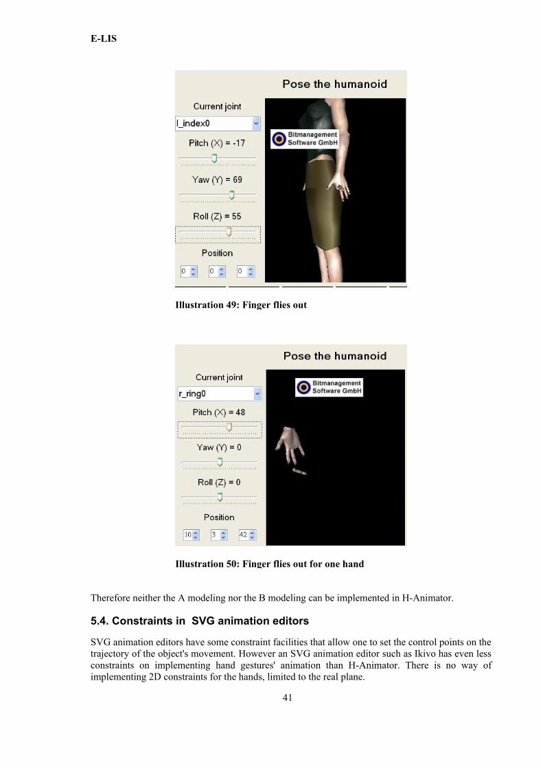
Illustration 49: Finger flies out.......................................................................................................... 41
Illustration 50: Finger flies out for one hand ....................................................................................41
Illustration 51: Finger bending, in Maya ..........................................................................................42
Illustration 52: The highest point and the lowest point..................................................................... 43
Illustration 53: The rightmost point and the leftmost point ..............................................................43
Illustration 54: Min and Max Limit, Z ............................................................................................. 44
Illustration 55: Finger bends into palm..............................................................................................44
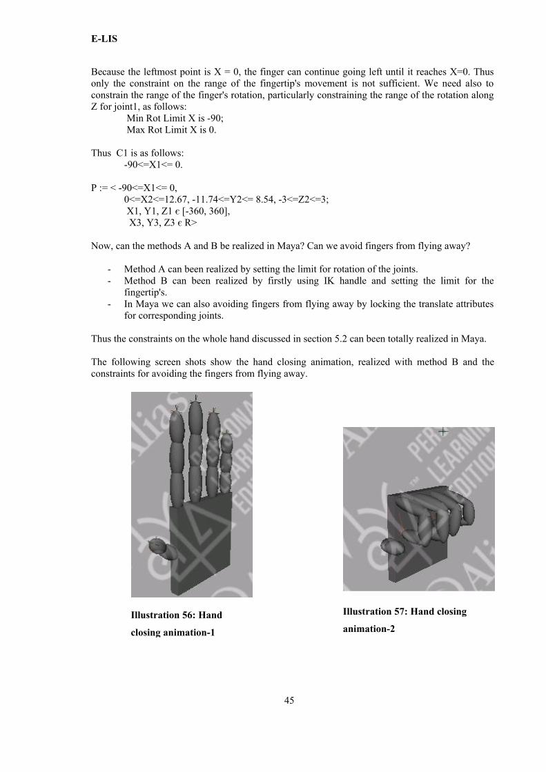
Illustration 56: Hand closing animation-1.........................................................................................45
Illustration 57: Hand closing animation-2.........................................................................................45
Illustration 58: Wrist bending forwards.............................................................................................51
Illustration 59: Wrist bending backward........................................................................................... 51
Illustration 60: Wrist bending sideways............................................................................................ 51
Illustration 61: Finger bending at the palm knuckles........................................................................ 51
Illustration 62: Finger bending at knuckles....................................................................................... 52
Illustration 63: Opening hand............................................................................................................52
Illustration 64: Wavelike movement................................................................................................. 52
Illustration 65: Hands towards each other......................................................................................... 52
Illustration 66: Hands away from each other.....................................................................................52
Illustration 67: Crossing hand............................................................................................................53
Illustration 68: Hand interlinking...................................................................................................... 53
Illustration 69: Hand insertion...........................................................................................................53
ix

E-LISIllustration 70: Change place of hands.............................................................................................. 53
x
E-LIS
Abstract
Hand gestures are not only natural, but are the basic components of sign languanges. Our work is concerned with movements of hands as in Italian Sign Language (Lingua Italiana dei Segni, LIS). LIS hand movements are of the following types:
Appendix A movements of the hands or fingers (e.g., cyclic);
Appendix B directional movements (e.g., upward, downward, backward, forward or diagonally);
Appendix C relational hand movement (e.g., inserting one hand into the other as a result of the movement, approaching hands);
Appendix D touching movements (e.g., hands touching the signer’s body).
In particular, for our thesis project we implemented the above LIS movements in the form required by the e-LIS project; this is a research project lead by the Institute for Specialized Communication and Multilingualism of EURAC in collaboration with Bozen-Bolzano Free University, whose aim is that of developing a bidirectional Electronic dictionary for LIS–Italian.
For carrying on our thesis project, we tested and used several animation editors (H-Animator, Maya, SVG animation editors) assessing their advantages or drawbacks with respect to the task at hand. We employ two kinds of editors for implementing hand animations: 2D animation editors and 3D animation editors. This choice is motivated by the fact that the e-LIS project provides two navigation interfaces to the electronic dictionary.
The first navigation interface is a simple interface for the current Internet version of the dictionary; this kind of interface forced us to create and animate abstract models of the hand (i.e., not related to any specific hand shape). 2D animation editors, namely SVG animation editors, were chosen for this task because they are sufficiently powerful for animating our abstract models of the hand (that is, non-realistic hands), and because the resulting animations are sufficiently light in size for this navigation interface.
The second is an intelligent interface for the dictionary based on the ELIS-ontology [A1]; this interface is still under development. We tested 3D animation editors, namely H-Animator and Maya, and compared them for realizing 3D hand gestures aimed at this more sophisticated navigation interface.
In this thesis, we describe the implementations of the required hand animations for the e-LIS project with the aforementioned animation editors. Testing different editors helped us in investigating the relevant features that the optimal animation editor for hand gestures should have.
In particular, we discuss how constraint modeling would improve such editors; for instance, the possibility of setting constraints on the distance between hand joints would avoid fingers from ‘flying off’ the hand. We propose two main models of hand constraints, and we assess whether and how these can be implemented in the tested animation editors.
xi

E-LIS
xii
E-LIS
Chapter 1. Introduction
1.1. Thesis rationale
The e-LIS project, for which we worked, aims at the creation of the first Electronic bidirectional dictionary for Italian Sign Language – Italian (Verbal Language). In this thesis, we focus on the animation of hand gestures for LIS (Lingua Italiana dei Segni, Italian Sign Language). We chose to use two kinds of editors for implementing hand gestures animations: 2D animation editors and 3D animation editors. This choice is motivated by the fact that the e-LIS project provides two navigation interfaces to the electronic dictionary.
The first navigation interface is a simple interface for the current Internet version of the dictionary; this kind of interface forced us to create and animate abstract models of the hand (i.e., not related to any specific hand shape). 2D animation editors were chosen for this task because they are sufficiently powerful for animating our abstract models of the hand (that is, non-realistic hands), and because the resulting animations are sufficiently light in size for this navigation interface.
The second is an intelligent interface for the dictionary based on the ELIS-ontology [A1]; this interface is still under development. We tested 3D animation editors and compared them for realising 3D hand gestures, which are aimed at this more sophisticated navigation interface.
We did not adopt this rationale in structuring the thesis. Rather the thesis develops along the thread of hand gesture animations for Italian Sign Language, possibly with constraints, an issue which is common to both the aforementioned approaches. However the reader should keep in mind the two different goals while reading this thesis.
1.2. Who can benefit from this thesis
Two main research fields converge in this thesis: that of Italian Sign Language, namely a visual language based on body gestures used in deaf communities, mainly; that of human computer interfaces.
Thus there are two kinds of readers who can benefit from this thesis: Italian Sign Language experts and computer scientists interested in the development of human interfaces.
1.3. Thesis structure
The material of this thesis is divided in four main chapters, outlined as follows.
o Chapter 2 provides an introduction to sign languages, focusing on Italian sign language and its relation to Italian verbal language.
o Chapter 3 provides an introduction to animation editors—H-Animator, Maya, SVG animation editors. It also attempts at assessing their advantages and drawbacks with respect to the task at hand.
o Chapter 4 details the implementation of the required hand gesture animations. It first describes the work done with H-Animator. Then it describes how to implement 3D hand animations in Maya and 2D hand animations in SVG editors separately. In the end, it describes how to implement specific movements, e.g., the twisting movements, of Italian Sign Language.
1

E-LIS
o Chapter 5 first provides two methods for modeling hand constraints. Then it discusses how to model these constraints in H-Animator, SVG animation editors and Maya separately.
Chapter 6 concludes this thesis with an assessment of our work and of the issues open for future research.
2
E-LIS
Chapter 2. LIS Signs
2.1. Background on LIS movements
A Sign Language (SL) is a visual language based on body gestures instead of sound to convey meaning. It simultaneously combines shapes, orientations and movements of the hands, as well as non-manual components. SLs are not pantomime, nor are they a visual rendition of the related Verbal Language (VL). They have rich, complex spatial grammars of their own, e.g.: a sign can involve one hand (the so-called dominant hand) or both hands; these can be symmetrically placed or not.
In this thesis we are interested in hand movements of Lingua Italiana dei Segni (LIS, Italian Sign Language). The category “movement of the hands” can be sub-divided in:
o movement of the hands or fingers (e.g., cyclic);
o directed movement (e.g., upward, downward, backward, forward or diagonally);
o relational hand movement (e.g., inserting one hand into the other as a result of the movement, approaching hands);
o touching movement (e.g., hands touching the signer's body).
In this thesis, we survey the animation tools and techniques we used to animate the aforementioned hand movements for the e-LIS project.
2.2. Background on the e-LIS project
The e-LIS project is a research project lead by the European Academy of Bozen-Bolzano (EURAC). Main partners of the project are the ALBA deaf cooperative of Turin and the Free University of Bozen-Bolzano (FUB).
The e-LIS project aims at the creation of the first Electronic bilingual dictionary of Italian Sign Language–Italian. The e-LIS dictionary employs the same transcription system adopted in the paper dictionary by Radutzky; this is described, for instance, in [A1].
The electronic format is particularly convenient for a spatial language such as LIS; for instance, it allows for videos and electronic images to be integrated in the dictionary and used to display signs. As the dictionary aims at reaching as many users as possible, developing the dictionary as a web application is the natural choice.
2.3. Our role in the e-LIS project
As mentioned in Chapter 1, the e-LIS project provides two navigation interfaces to the electronic dictionary.
Our role in this project was to learn, use and assess two kinds of animation editors:
o 2D animation editors for animating hand moels (that is, non-realistic hands), sufficiently light in size and abstract for the “simple” navigation interface;
o 3D animation editors for animating more realistic hand-gestures for the “intelligent” interface to the dictionary based on the ELIS-ontology [A1].
3

E-LIS
4
E-LIS
Chapter 3. Animation Editors
3.1. Introduction
For implementing the required hand gestures for LIS, We used and tested the following animation editors: H-Animator, Maya, SVG animation editors. Section 3.2 provides an introduction to H-Animator, Maya, SVG animation editors and Section 3.3 describes their pros and contras for the task at hand.
3.2. Introduction to H-Animator, Maya, SVG animation editors
In the remainder of this section, we give the essential basic information concerning H-Animator, Maya, and the used SVG animation editors.
3.2.1. Introduction to H-Animator
H-AnimatorX3D [C1] is an initiative to leverage 3D as digital media as easily as we do with text and 2D graphics. It provides the technology to enable customers to view, modify, customize and reuse 3D visualizations in other applications on the web or on any network device from cell phones to supercomputers.
H-Animator, version 0.2, [C2] is a visual tool which lets you model, reuse and share X3D animations for H-Animator humanoids. With H-Animator one can:
o create standard H-Animator humanoids starting from existing X3D humanoids; o visually model simple X3D humanoid animations, even if one does not know the
X3D language; o compose complex animations by visually concatenating different simple ones.
Software requirements
To use H-Animator one needs Windows XP with BS Contact 7.0 and the .NET Framework 2.0 Redistributable Package installed.
3.2.2. Introduction to Maya
MayaMaya [C3] is one of the most used software applications for the creation of 3D digital animations and visual effects. Maya provides a comprehensive suite of tools for 3D content creation work ranging from modeling, animation, and dynamics through to painting and rendering to name but a few.
Maya Personal learning EditionWe used Maya Personal learning Edition [C4] for implementing hand's animations. Maya Personal Learning Edition is a special version of Maya® software which provides free access to Maya for non-commercial use.
5
E-LIS
3.2.3. Introduction to SVG animation editors
3.2.3.1. What is SVG?
SVG (Scalable Vector Graphics) is an XML language for describing two-dimensional graphics and graphical applications [C5].
A bitmap graphic is created from rows of different colored pixels that together form an image. In their simplest form, bitmaps have only two colors, with each pixel being either black or white. With increasing complexity, an image can include more colors; photograph-quality images may have millions. Examples of bitmap graphic formats include GIF, JPEG, PNG, TIFF, XBM, BMP, and PCX as well as bitmap fonts. The image displayed on a computer monitor is also a bitmap, as are the outputs of printers, scanners, and similar devices. They are created using paint programs such as Adobe Photoshop.
Vector graphics are constructed using mathematical formulas describing shapes, colors, and placement. Rather than a grid of pixels, a vector graphic consists of shapes, curves, lines, and text, which together make a picture. While a bitmap image contains information about the color of each pixel, a vector graphic contains instructions about where to place each of the components. It is even possible to embed a bitmap graphic within a vector graphic, which is how vector-bitmap hybrid graphics work. It is not possible, however, to embed vector information within a bitmap. Examples of vector graphic formats are PICT, EPS, WMF and SVG.
The SVG format is particularly suited for the e-LIS animations for two main reasons: - SVG files are rather light, which makes them suitable for a website full of images such as
the e-LIS website; - the resolution of SVG images does not degrade when the images are scaled, since SVG is a
vector graphics format [C6]; SVG images can be zoomed in and resized by the reader as needed and still all details are kept visible.
3.2.3.2. SVG Syntax
SVG is an XML-based language. XML is a human-readable and flexible text markup-language. Simply stated, XML defines tag names enclosed by "<>", e.g., <circle>. Any XML tag can also have attributes. Attributes consist of a name and a value enclosed in quotation marks. For instance, cx, cy, and r are attributes of the circle element in <circle cx="0" cy="0" r="10">. If properly formatted, XML requires that every tag name be closed by an ending tag name, e.g. </circle>.
SVG exampleThe following is an example [C7] of an SVG image.
<?xml version="1.0" standalone="no"?><!DOCTYPE svg PUBLIC "-//W3C//DTD SVG 1.1//EN" "http://www.w3.org/Graphics/SVG/1.1/DTD/svg11.dtd">
<svg width="100%" height="100%" version="1.1" xmlns="http://www.w3.org/2000/svg">
<circle cx="100" cy="50" r="40" stroke="black"stroke-width="2" fill="red"/>
</svg>
6
E-LIS
The first line contains the XML declaration. The standalone attribute specifies whether the SVG file "stands alone", or contains a reference to an external file; if standalone is set to "no" then the SVG document has a reference to an external file − in this case, the DTD.
The second and the third line refer to the external SVG DTD. The DTD is located at <http://www.w3.org/Graphics/SVG/1.1/DTD/svg11.dtd>. The DTD resides at the W3C and it contains all the allowed SVG elements.
The SVG code starts with the opening <svg> tag and ends with the closing </svg> tag. This is the root element. The width and height attributes set the width and height of the SVG image. The version attribute defines the SVG version to be used and the xmlns attribute defines the SVG namespace. The closing </svg> tag closes the root SVG element and the document.
Within the opening and closing <svg> tags, one find the <circle> tag. The cx and cy attributes define the x and y coordinates of the center of the circle. If cx and cy are omitted, the circle's center is set to (0,0). The r attribute defines the radius of the circle. The stroke and stroke-width attributes control how the outline of a shape appears. In the above example, we set the outline of the circle to be 2px wide and black. The fill attribute refers to the color inside a shape, which is set to red in the above example.
3.2.3.3. The chosen SVG animator
We used the Sketsa editor for creating SVG files and "Ikivo Animator" for animating them. Both programs are available at [C8].
Sketsa is a vector-based drawing application based on SVG and is comprised of many parts that work together to help in developing one's artwork. Sketsa requires Java™ VM (JRE) 1.5 or higher which is available from [C9]. As a cross platform application, Sketsa runs on any platform that support Java™ 1.5 or higher, for example: Microsoft Windows, Unix or Linux.
Ikivo Animator is an SVG animation composer. We chose Ikivo as our SVG animator because it is easy to master and powerful enough for creating the required animations.
Unfortunately, most browsers do not support animated SVG images, but one can install SVG plug-in which can be downloaded at [C10].
3.3. Assessment of the tested animation editors
In the remainder, we discuss how the pros and contras of the tested animation editors for the task at hand, that is, LIS animated signs.
3.3.1. The case of H-Animator
Advantages H-Animator can been used to build simple 3 dimensional humanoid animations. H-Animator simplifies the modeling process by creating a fast and easy-to-use visual tool which helps the user in each of the modeling phases [C11]. H-Animator comes with some X3D humanoids so that one does not need to draw them directly for their animation.
Drawbacks
H-Animator lacks constraint modeling and reasoning; there are no facilities for modeling and reasoning with constraints on the hand, such as “the angle between two adjacent fingers is acute”.
7
E-LIS
Therefore when users need to create several animations with the same image, e.g., the hands, they have to go through a good deal of manual repetitive work.
3.3.2. The case of Maya
AdvantagesMaya is very powerful editor which allows one to build 3 dimensional animations. Maya can build realistic models of the hand with almost all kinds of 3D signs we need for LIS. Maya provides facilities for constraint modeling, which avoid the necessity of doing tedious repetitive tasks; for instance, with Maya one can constrain the range of fingers’ movements and the angles of fingers rotation.
DrawbacksThe interface of Maya is complex hence difficult to master in a short time. Moreover, Maya does not support the SVG format; AVI is the only suitable format for the e-LIS project Maya allows for. However, even for simple hand animations, the AVI files produced with Maya are quite big in size. For example, the size of 'up.avi' is 304 KB. This makes AVI files quite unsuitable for a web-based application with several images such as e-LIS.
3.3.3. The case of SVG animators
AdvantagesAs written above, SVG files are rather light and their resolution does not degrade when they are scaled. Take 'up.svg' for example: its size is only 10KB, whereas the size of 'up.avi' produced with Maya is 304KB. Certain bitmap images can also be imported in Sketsa and saved as SVG files. This is definitely convenient; despite their easy of use, SVG drawing tools do not provide many drawing tools yet; for instance, with Sketsa it is not possible to draw dotted lines (e.g., there is no eraser tool); so we created dotted lines in jpeg format, then we imported them in Sketsa.
Moreover, the SVG animation editors we used are easy to learn and master. For instance, it took less than one week to learn Ikivo Animator and Sketesa. The learning curve is definitely faster than, say, with Maya.
DrawbacksWith SVG animators it is difficult to simulate 3D images. When one needs to provide even some basic 3D effects, one needs to draw all the necessary frames every 0.1 second. This is indeed quite a time consuming job.
8
E-LIS
Chapter 4. Animated LIS hand gestures
4.1. Introduction
This chapter describes how we implemented the required hand gestures for e-LIS. Section 4.2 describes the work we have done in H-Animator. Section 4.3 describes how to implement hand animations in Maya. Section 4.4 describes how to implement the LIS hand animations with SVG editors. Section 4.5 describes how to implement the twisting movement using Maya and SVG editors.
4.2. H-Animator
For the hand gesture's animations, we need to focus on hands. Thus, we need to find a way to only use the hand instead of the whole human body. The steps to do so are described in detailed in the remainder of this section.
(a) Create a new folder; save it, for instance, as “righthand”.
(b) Open the folder of Helena, the default humanoid. Select the following files concerning the right hand: r_hand, r_index_distal, r_index_middle, r_index_proximal, r_middle_distal, r_middle_middle, r_middle_proximal, r_pinky_distal, r_pinky_middle, r_pinky_proximal, r_ring_distal, r_ring_middle, r_ring_proximal, r_thumb_distal, r_thumb_proximal. Copy these files to the folder named 'righthand'.
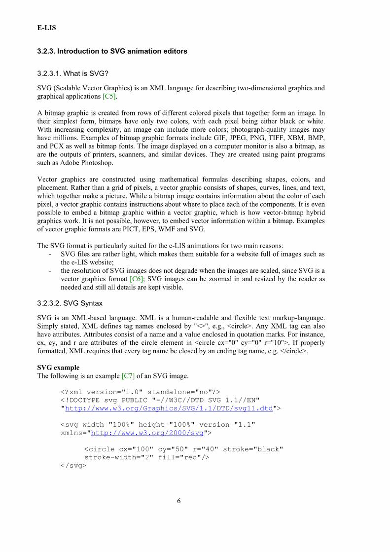
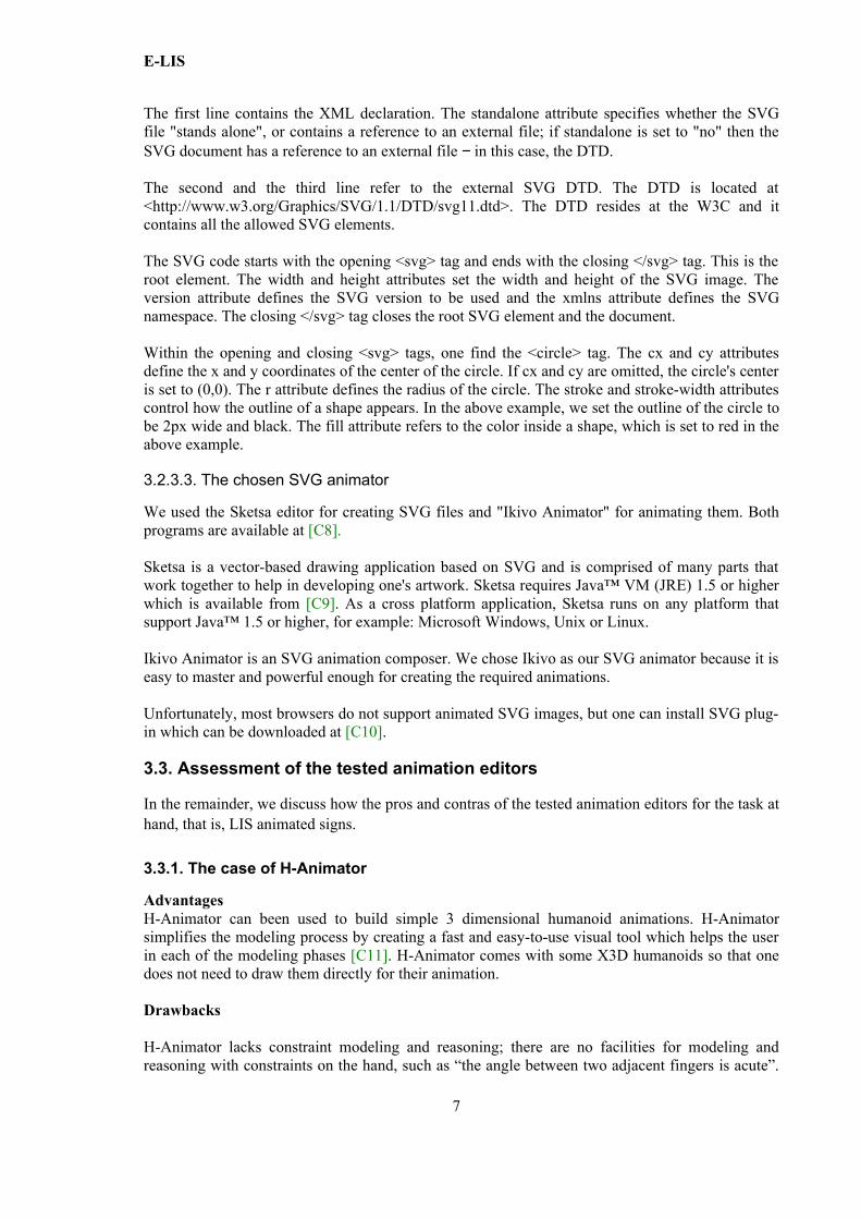
(c) Launch H-Animator, then select the JointPlacer button in the start window. Follow the instructions on the right for the subsequent window. Select the Create New button and ‘righthand' in the following window as shown in the following image.
9
Illustration 1: Segments window in H-Animator
E-LIS
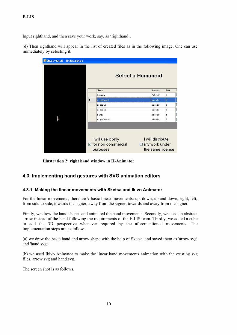
Input righthand, and then save your work, say, as ‘righthand’.
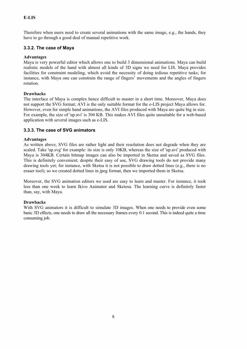
(d) Then righthand will appear in the list of created files as in the following image. One can use immediately by selecting it.
4.3. Implementing hand gestures with SVG animation editors
4.3.1. Making the linear movements with Sketsa and Ikivo Animator
For the linear movements, there are 9 basic linear movements: up, down, up and down, right, left, from side to side, towards the signer, away from the signer, towards and away from the signer.
Firstly, we drew the hand shapes and animated the hand movements. Secondly, we used an abstract arrow instead of the hand following the requirements of the E-LIS team. Thirdly, we added a cube to add the 3D perspective whenever required by the aforementioned movements. The implementation steps are as follows:
(a) we drew the basic hand and arrow shape with the help of Sketsa, and saved them as 'arrow.svg' and 'hand.svg';
(b) we used Ikivo Animator to make the linear hand movements animation with the existing svg files, arrow.svg and hand.svg.
The screen shot is as follows.
10
Illustration 2: right hand window in H-Animator
E-LIS
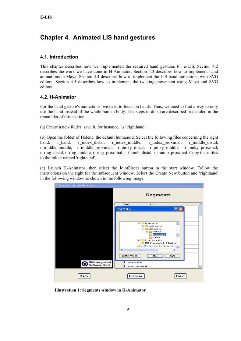
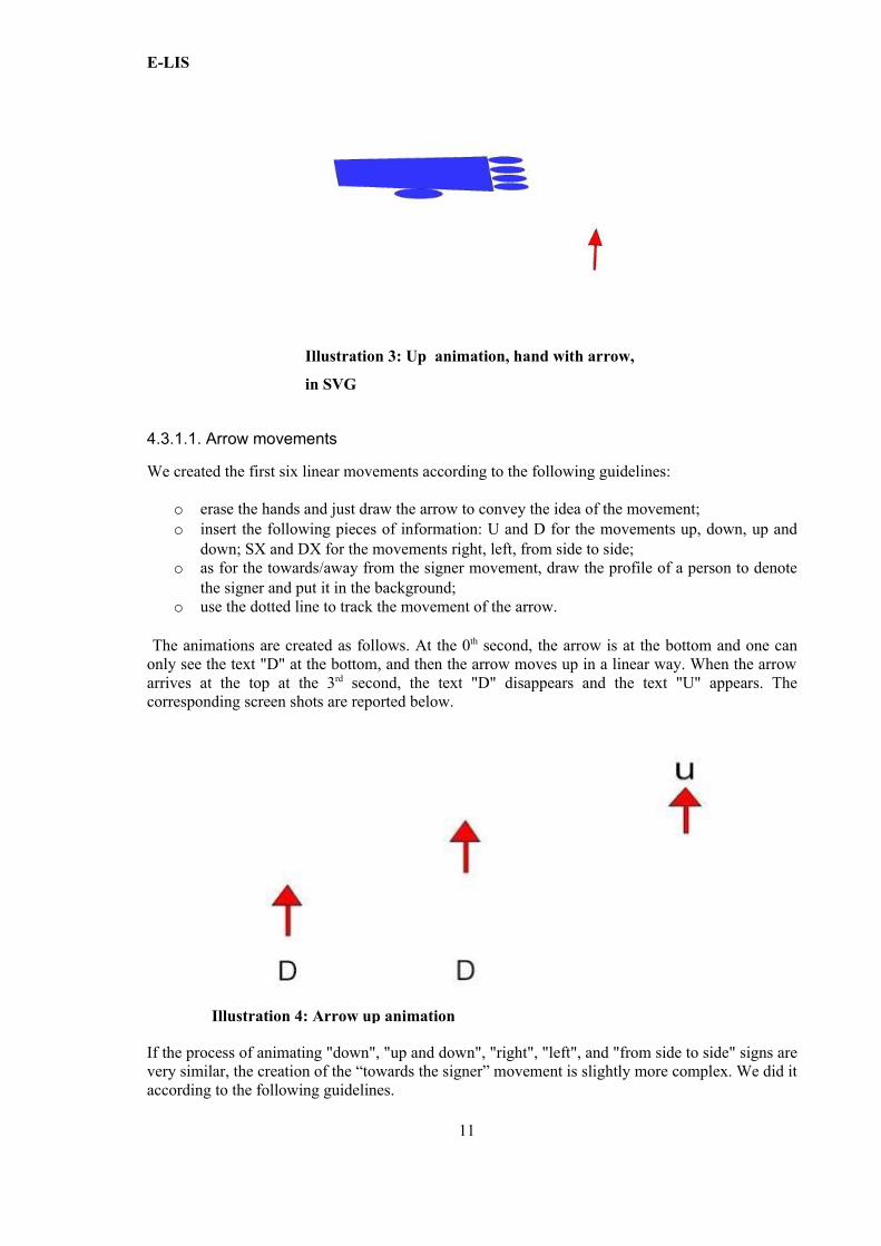
4.3.1.1. Arrow movements
We created the first six linear movements according to the following guidelines:
o erase the hands and just draw the arrow to convey the idea of the movement; o insert the following pieces of information: U and D for the movements up, down, up and
down; SX and DX for the movements right, left, from side to side;o as for the towards/away from the signer movement, draw the profile of a person to denote
the signer and put it in the background;o use the dotted line to track the movement of the arrow.
The animations are created as follows. At the 0th second, the arrow is at the bottom and one can only see the text "D" at the bottom, and then the arrow moves up in a linear way. When the arrow arrives at the top at the 3rd second, the text "D" disappears and the text "U" appears. The corresponding screen shots are reported below.
If the process of animating "down", "up and down", "right", "left", and "from side to side" signs are very similar, the creation of the “towards the signer” movement is slightly more complex. We did it according to the following guidelines.
11
Illustration 4: Arrow up animation
Illustration 3: Up animation, hand with arrow,
in SVG
E-LIS
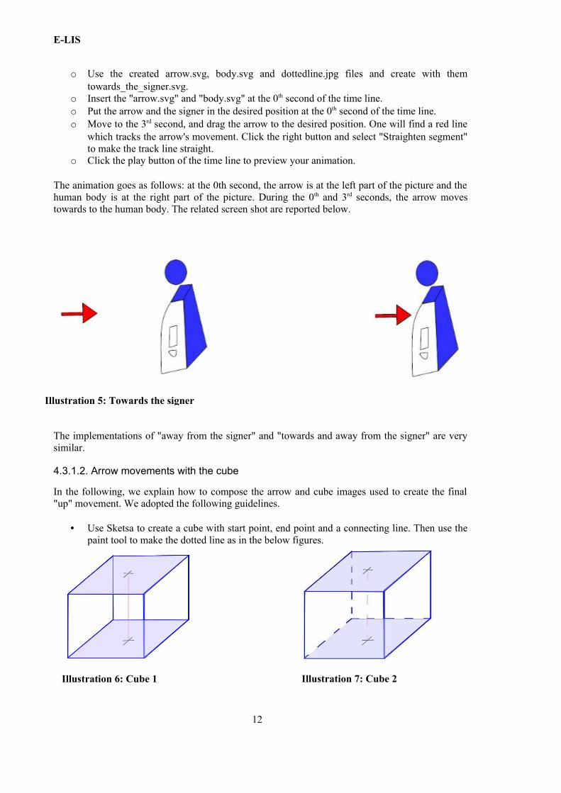
o Use the created arrow.svg, body.svg and dottedline.jpg files and create with them towards_the_signer.svg.
o Insert the "arrow.svg" and "body.svg" at the 0th second of the time line.o Put the arrow and the signer in the desired position at the 0th second of the time line.o Move to the 3rd second, and drag the arrow to the desired position. One will find a red line
which tracks the arrow's movement. Click the right button and select "Straighten segment" to make the track line straight.
o Click the play button of the time line to preview your animation.
The animation goes as follows: at the 0th second, the arrow is at the left part of the picture and the human body is at the right part of the picture. During the 0th and 3rd seconds, the arrow moves towards to the human body. The related screen shot are reported below.
The implementations of "away from the signer" and "towards and away from the signer" are very similar.
4.3.1.2. Arrow movements with the cube
In the following, we explain how to compose the arrow and cube images used to create the final "up" movement. We adopted the following guidelines.
• Use Sketsa to create a cube with start point, end point and a connecting line. Then use the paint tool to make the dotted line as in the below figures.
12
Illustration 5: Towards the signer
Illustration 6: Cube 1 Illustration 7: Cube 2
E-LIS
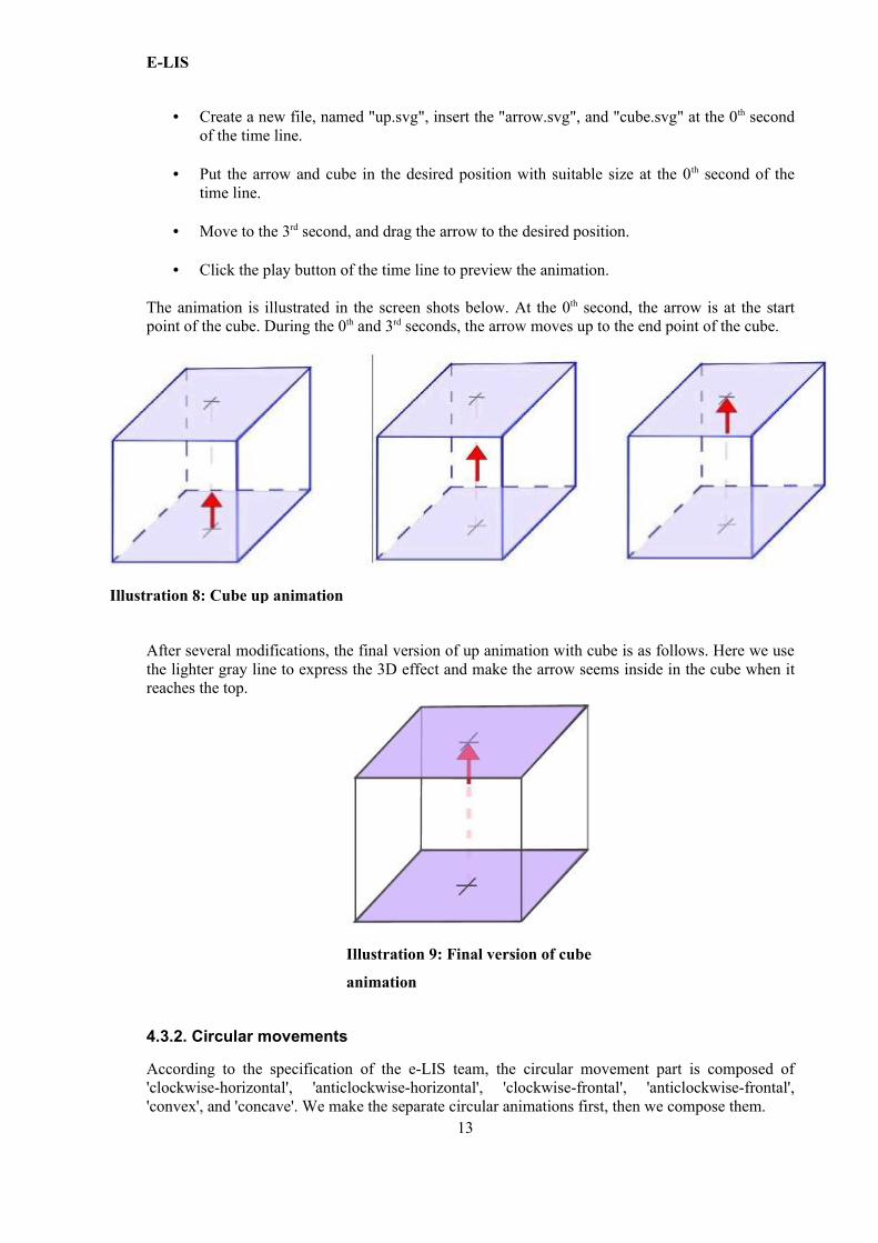
• Create a new file, named "up.svg", insert the "arrow.svg", and "cube.svg" at the 0th second of the time line.
• Put the arrow and cube in the desired position with suitable size at the 0th second of the time line.
• Move to the 3rd second, and drag the arrow to the desired position.
• Click the play button of the time line to preview the animation.
The animation is illustrated in the screen shots below. At the 0th second, the arrow is at the start point of the cube. During the 0th and 3rd seconds, the arrow moves up to the end point of the cube.
After several modifications, the final version of up animation with cube is as follows. Here we use the lighter gray line to express the 3D effect and make the arrow seems inside in the cube when it reaches the top.
4.3.2. Circular movements
According to the specification of the e-LIS team, the circular movement part is composed of 'clockwise-horizontal', 'anticlockwise-horizontal', 'clockwise-frontal', 'anticlockwise-frontal', 'convex', and 'concave'. We make the separate circular animations first, then we compose them.
13
Illustration 9: Final version of cube
animation
Illustration 8: Cube up animation
E-LIS
(1) Make a general animation plan.We separate the composite circular movement into three parts: horizontal movement, vertical movement and frontal movement.
Make the plan for each separate movement as follows: horizontal movement: 0-5 second;
clockwise: 0-2 second;time span: 2-3 second;anticlockwise: 3-5 second;
time span: 5-7 second;vertical movement: 7-12 second;
clockwise: 7-9 second;time span: 9-10 second;anticlockwise: 10-12 second;
time span:12-14 second;frontal movement: 14-19 second;
clockwise: 14-16 second;time span: 16-17second;anticlockwise: 17-19 second.
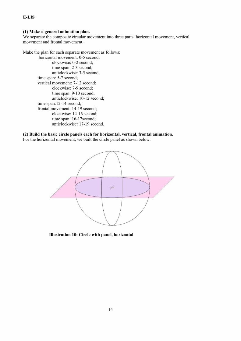
(2) Build the basic circle panels each for horizontal, vertical, frontal animation. For the horizontal movement, we built the circle panel as shown below.
14
Illustration 10: Circle with panel, horizontal
E-LIS
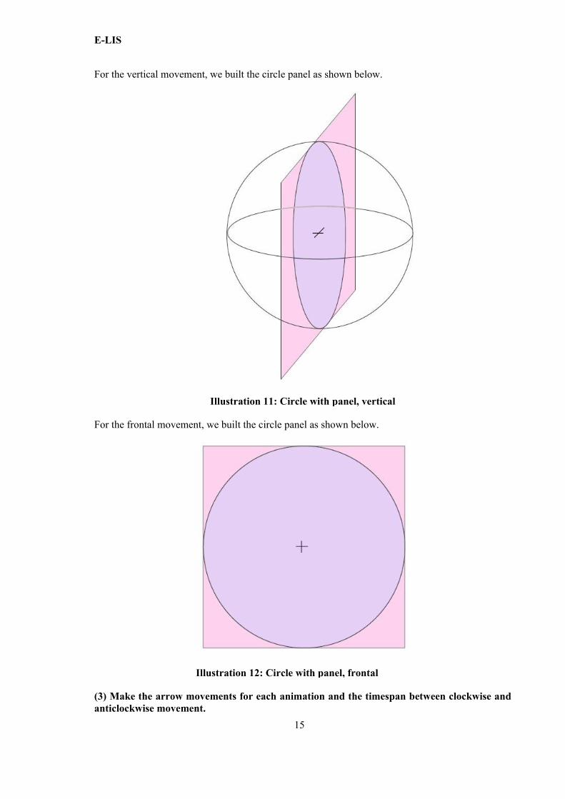
For the vertical movement, we built the circle panel as shown below.
For the frontal movement, we built the circle panel as shown below.
(3) Make the arrow movements for each animation and the timespan between clockwise and anticlockwise movement.
15
Illustration 12: Circle with panel, frontal
Illustration 11: Circle with panel, vertical
E-LIS
To make the arrow movements along the circle, one can use the control point to adjust the trajectory of the movement. It is also necessary to adjust the rotation of the arrow for every 0.1 second, setting the time span to 1 second between clockwise and anti-clockwise movement.
(4) Compose the horizontal, vertical, frontal animation into one animation.Now we only need to insert 'horizontal.svg', 'vertical.svg' and 'frontal.svg' which have been already made before. Put these three animations in the same position. Make the visibility for each animation as follows:
Horizontal movement is visible from the 0th to the 7th second;Vertical movement is visible from the 7th to the 14th second;Frontal movement is visible from the 14th to the 19th second.
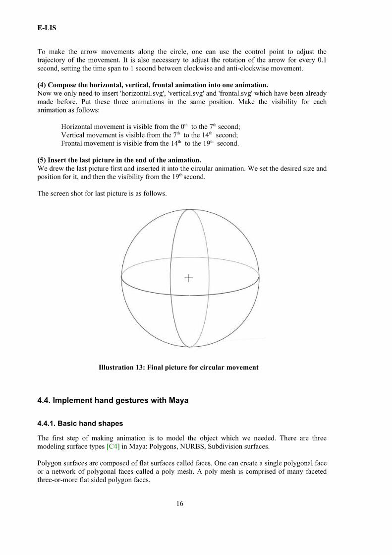
(5) Insert the last picture in the end of the animation. We drew the last picture first and inserted it into the circular animation. We set the desired size and position for it, and then the visibility from the 19th second.
The screen shot for last picture is as follows.
4.4. Implement hand gestures with Maya
4.4.1. Basic hand shapes
The first step of making animation is to model the object which we needed. There are three modeling surface types [C4] in Maya: Polygons, NURBS, Subdivision surfaces.
Polygon surfaces are composed of flat surfaces called faces. One can create a single polygonal face or a network of polygonal faces called a poly mesh. A poly mesh is comprised of many faceted three-or-more flat sided polygon faces.
16
Illustration 13: Final picture for circular movement
E-LIS
NURBS (Non-Uniform Rational B-splines) use a method of mathematically describing curves and surfaces that are well suited to 3D applications. NURBS are characterized by the smooth organic forms they produce.
Subdivision surfaces possess characteristics of both NURBS and polygonal surfaces as well as other features not offered by the other surface types.
Here we chose Polygon surfaces to model the hands. Because Polygon surfaces is particularly useful when simple forms are required and can be rendered more quickly because polygonal surfaces are described with the smallest amount of data.
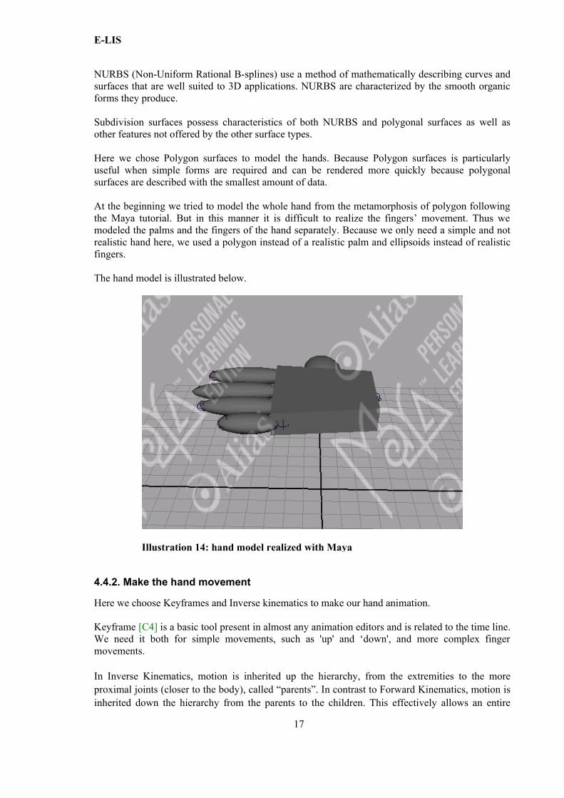
At the beginning we tried to model the whole hand from the metamorphosis of polygon following the Maya tutorial. But in this manner it is difficult to realize the fingers’ movement. Thus we modeled the palms and the fingers of the hand separately. Because we only need a simple and not realistic hand here, we used a polygon instead of a realistic palm and ellipsoids instead of realistic fingers.
The hand model is illustrated below.
4.4.2. Make the hand movement
Here we choose Keyframes and Inverse kinematics to make our hand animation.
Keyframe [C4] is a basic tool present in almost any animation editors and is related to the time line. We need it both for simple movements, such as 'up' and ‘down', and more complex finger movements.
In Inverse Kinematics, motion is inherited up the hierarchy, from the extremities to the more proximal joints (closer to the body), called “parents”. In contrast to Forward Kinematics, motion is inherited down the hierarchy from the parents to the children. This effectively allows an entire
17
Illustration 14: hand model realized with Maya
E-LIS
hand to be posed by moving one object: a handle. As the handle is moved around, the extremities follow it, and the joints above it in the hierarchy readjust accordingly. One can also impose constraints with IK. We chose IK for finger moving. Maya provides inverse kinematics tools called "IK handles". And we chose IK handle for finger bending animations.
We used Keyframe as animation tool to make the linear hand movements: up, down, up and down, left, right, from side to side, towards the signer, away from the signer, towards and away from the signer.
Take the 'up' movement for example. The steps involved in its creation are the following.
(a) Open the scene 'hand.mp'. (b) Set the playback range for the scene.(c) In the Playback End Time box, enter 24.At a default playback rate of 24 frames per second,
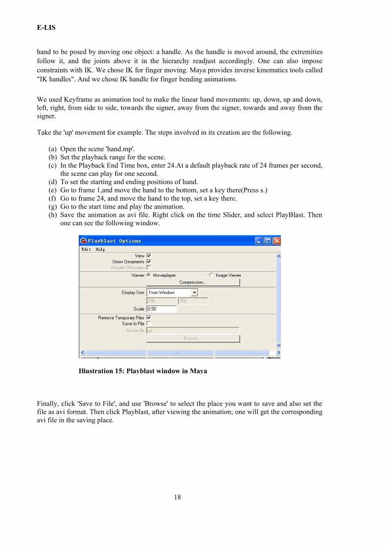
the scene can play for one second.(d) To set the starting and ending positions of hand.(e) Go to frame 1,and move the hand to the bottom, set a key there(Press s.) (f) Go to frame 24, and move the hand to the top, set a key there.(g) Go to the start time and play the animation. (h) Save the animation as avi file. Right click on the time Slider, and select PlayBlast. Then
one can see the following window.
Finally, click 'Save to File', and use 'Browse' to select the place you want to save and also set the file as avi format. Then click Playblast, after viewing the animation; one will get the corresponding avi file in the saving place.
18
Illustration 15: Playblast window in Maya
E-LIS
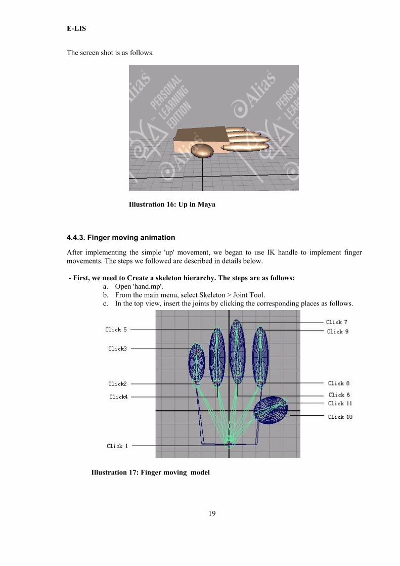
The screen shot is as follows.
4.4.3. Finger moving animation
After implementing the simple 'up' movement, we began to use IK handle to implement finger movements. The steps we followed are described in details below.
- First, we need to Create a skeleton hierarchy. The steps are as follows:a. Open 'hand.mp'.b. From the main menu, select Skeleton > Joint Tool. c. In the top view, insert the joints by clicking the corresponding places as follows.
19
Illustration 17: Finger moving model
Illustration 16: Up in Maya
E-LIS
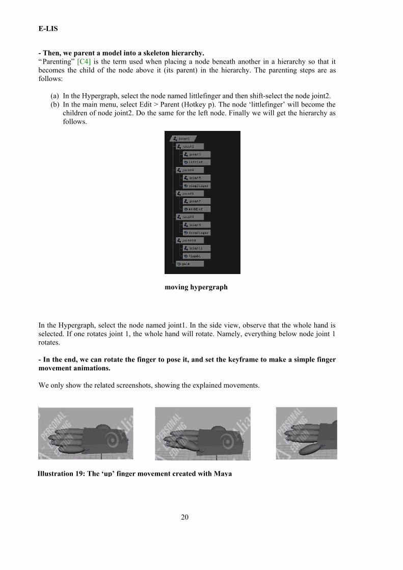
- Then, we parent a model into a skeleton hierarchy.“Parenting” [C4] is the term used when placing a node beneath another in a hierarchy so that it becomes the child of the node above it (its parent) in the hierarchy. The parenting steps are as follows:
(a) In the Hypergraph, select the node named littlefinger and then shift-select the node joint2. (b) In the main menu, select Edit > Parent (Hotkey p). The node ‘littlefinger’ will become the
children of node joint2. Do the same for the left node. Finally we will get the hierarchy as follows.
In the Hypergraph, select the node named joint1. In the side view, observe that the whole hand is selected. If one rotates joint 1, the whole hand will rotate. Namely, everything below node joint 1 rotates.
- In the end, we can rotate the finger to pose it, and set the keyframe to make a simple finger movement animations.
We only show the related screenshots, showing the explained movements.
20
moving hypergraph
Illustration 19: The ‘up’ finger movement created with Maya
E-LIS
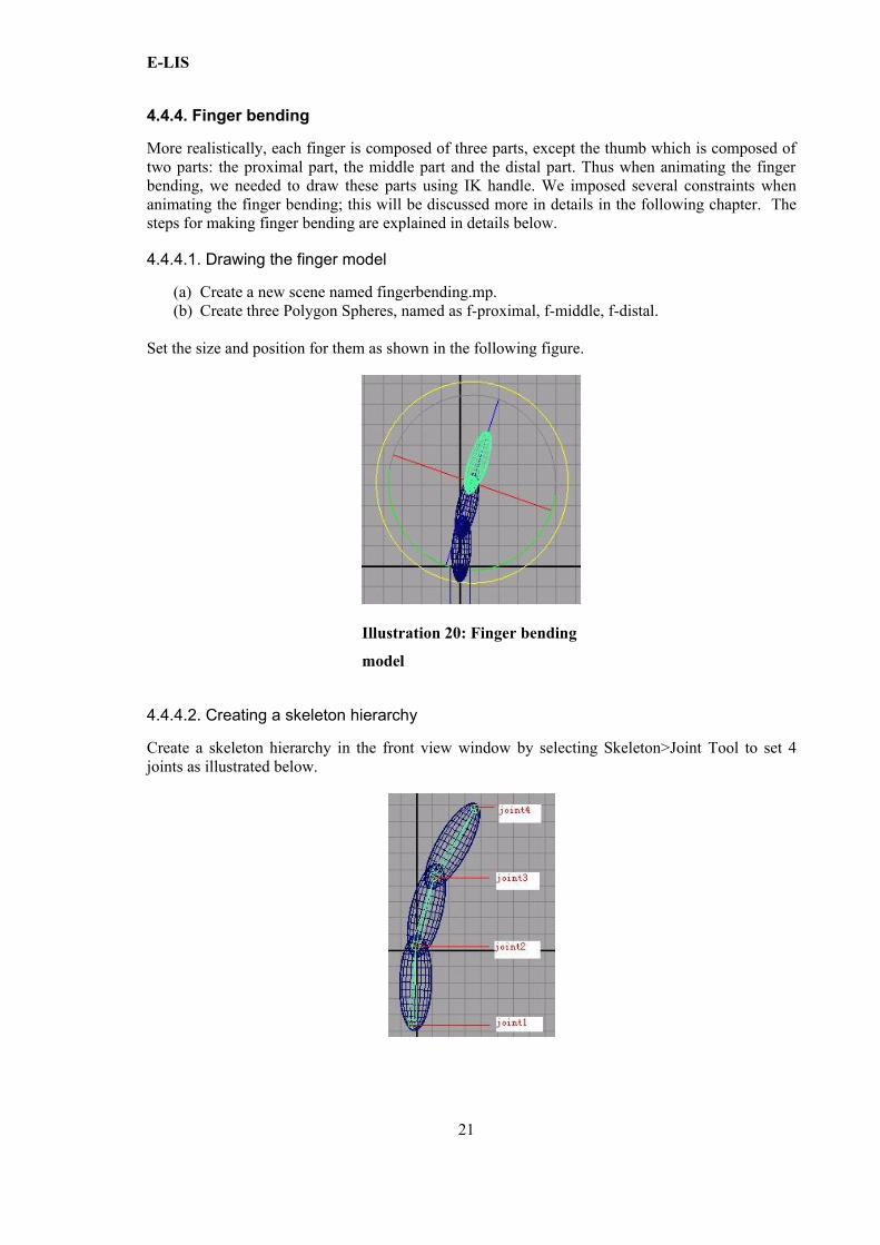
4.4.4. Finger bending
More realistically, each finger is composed of three parts, except the thumb which is composed of two parts: the proximal part, the middle part and the distal part. Thus when animating the finger bending, we needed to draw these parts using IK handle. We imposed several constraints when animating the finger bending; this will be discussed more in details in the following chapter. The steps for making finger bending are explained in details below.
4.4.4.1. Drawing the finger model
(a) Create a new scene named fingerbending.mp.(b) Create three Polygon Spheres, named as f-proximal, f-middle, f-distal.
Set the size and position for them as shown in the following figure.
4.4.4.2. Creating a skeleton hierarchy
Create a skeleton hierarchy in the front view window by selecting Skeleton>Joint Tool to set 4 joints as illustrated below.
21
Illustration 20: Finger bending
model
E-LIS
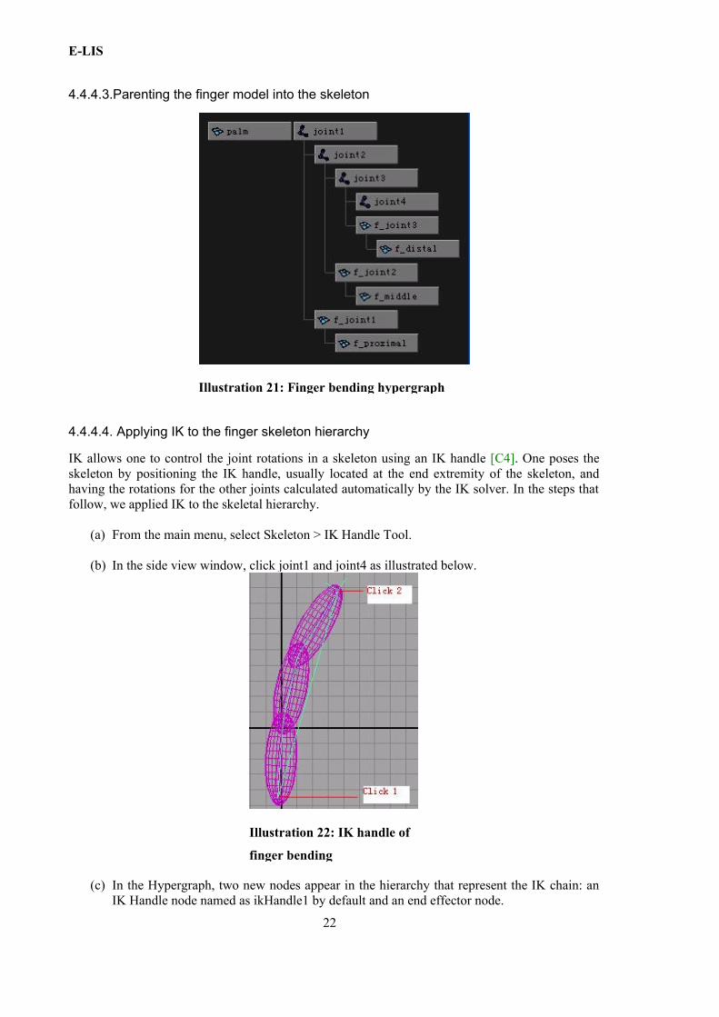
4.4.4.3.Parenting the finger model into the skeleton
4.4.4.4. Applying IK to the finger skeleton hierarchy
IK allows one to control the joint rotations in a skeleton using an IK handle [C4]. One poses the skeleton by positioning the IK handle, usually located at the end extremity of the skeleton, and having the rotations for the other joints calculated automatically by the IK solver. In the steps that follow, we applied IK to the skeletal hierarchy.
(a) From the main menu, select Skeleton > IK Handle Tool.
(b) In the side view window, click joint1 and joint4 as illustrated below.
(c) In the Hypergraph, two new nodes appear in the hierarchy that represent the IK chain: an IK Handle node named as ikHandle1 by default and an end effector node.
22
Illustration 22: IK handle of
finger bending
Illustration 21: Finger bending hypergraph

E-LIS
By observing a finger's movement, two items can be constrained probably: the range of the fingertip's movement and the angle of the joints' rotation. In order to view the finger’s bending in a clear way, we added a palm as shown below.
4.4.4.5. Constrain the range of the fingertip's movement
For constraining the range of the fingertip's movement, we used a control object to realize it as detailed in the following.
- Insert a control object Locator, named as locator1 by default.- Use locator1 to control IK handle node: ikHandle1.- First select the locator1 and then shift select the ikHandle1 node. The order of selection
when applying a constraint is important: one must select the constraining object first, and then item to be constrained as second. Then in the main menu, select Constrain, then Point. The Point Constraint Options window appears. In the Constraint Options window, select Maintain offset, and set the offset as 0,0,0. In this manner locator1 and ikHandle1 will be stuck together. Click add button to ensure the setting and add the point constraint.
- Try to move locator1; the IK handle system also moves by following locator1. Thus we have already used the control object to control the IK handle system's movement through controlling fingertip's movement.
- Make palm as the parent of lacator1 and ikHandle1.- Set the range of movement for fingertip. Take the Y axis's range for example. First try to
find the numbers for the highest and lowest points along the Y axis coordinate as shown below.
23
Illustration 23: Finger bending with palm

E-LIS
We got the following values: for the Highest point, Y is 8.54; for the Lowest point, Y is -11.74. - Open Attribute Editor of locator1.
o Expand the Limit Information attributes, and then the Translate attributes.o Fill in Min and Max number for Trans Limit Y with the number you got as
follows.
- Proceed in the same manner to get the range numbers along the X axis: the rightmost point is X equal to 12.67; the leftmost point is X equal to 0. Fill in the Trans Limit X.
24
Illustration 24: The highest point and the lowest point
Illustration 25: Attribute editor
Illustration 26: The rightmost point and the leftmost point
E-LIS
- Proceed in the same way to get the range numbers for the Z coordinates: the Min Limit for Z is equal to -3; the Max Limit for Z is equal to 3. Fill in the Trans Limit Z.
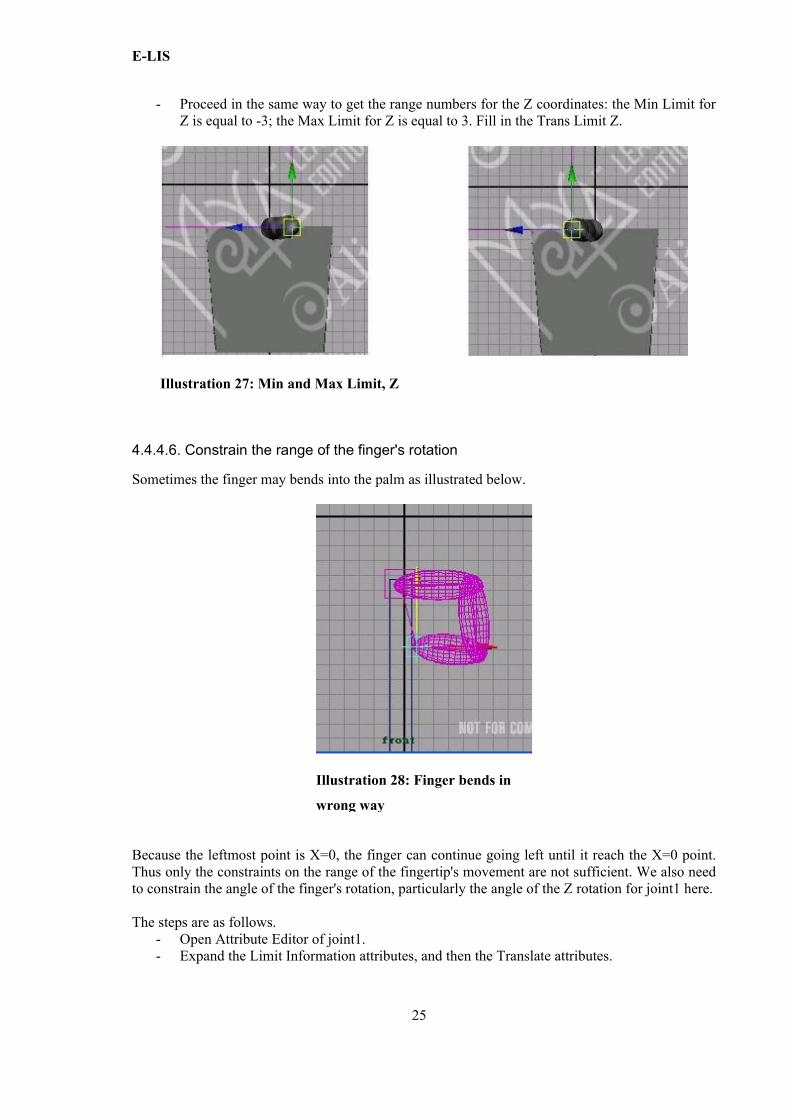
4.4.4.6. Constrain the range of the finger's rotation
Sometimes the finger may bends into the palm as illustrated below.
Because the leftmost point is X=0, the finger can continue going left until it reach the X=0 point. Thus only the constraints on the range of the fingertip's movement are not sufficient. We also need to constrain the angle of the finger's rotation, particularly the angle of the Z rotation for joint1 here.
The steps are as follows.- Open Attribute Editor of joint1.- Expand the Limit Information attributes, and then the Translate attributes.
25
Illustration 28: Finger bends in
wrong way
Illustration 27: Min and Max Limit, Z
E-LIS
By observing and rotating the finger carefully, we got the following values: Min Rot Limit is Z=-93; Max Rot Limit is Z=0. Fill in Min and Max number for Trans Limit Z with the numbers desired.
Thus when we move the finger until the following position, the finger cannot go into the palm anymore because of the constraints of the Z rotation for joint1.
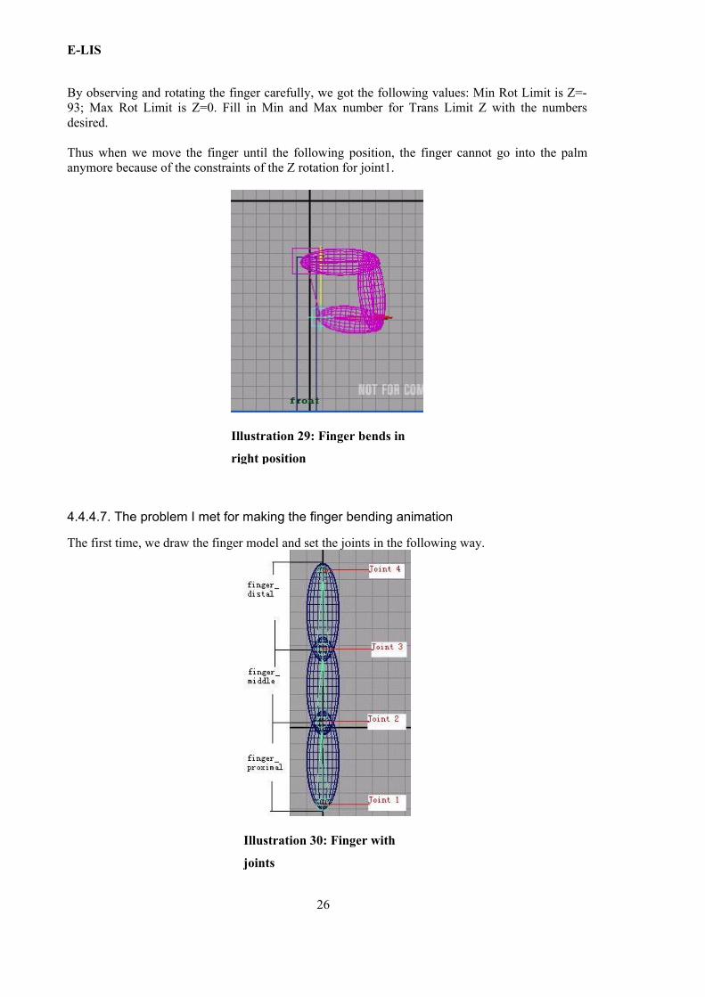
4.4.4.7. The problem I met for making the finger bending animation
The first time, we draw the finger model and set the joints in the following way.
26
Illustration 29: Finger bends in
right position
Illustration 30: Finger with
joints
E-LIS
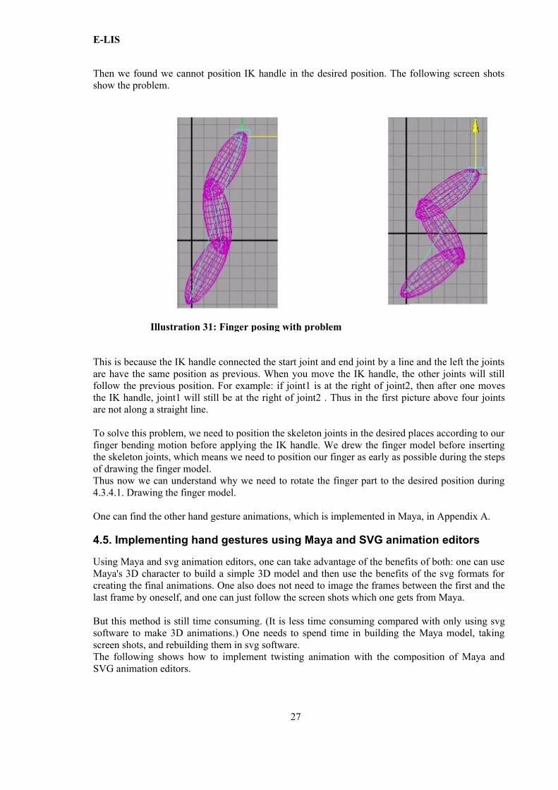
Then we found we cannot position IK handle in the desired position. The following screen shots show the problem.
This is because the IK handle connected the start joint and end joint by a line and the left the joints are have the same position as previous. When you move the IK handle, the other joints will still follow the previous position. For example: if joint1 is at the right of joint2, then after one moves the IK handle, joint1 will still be at the right of joint2 . Thus in the first picture above four joints are not along a straight line.
To solve this problem, we need to position the skeleton joints in the desired places according to our finger bending motion before applying the IK handle. We drew the finger model before inserting the skeleton joints, which means we need to position our finger as early as possible during the steps of drawing the finger model. Thus now we can understand why we need to rotate the finger part to the desired position during 4.3.4.1. Drawing the finger model.
One can find the other hand gesture animations, which is implemented in Maya, in Appendix A.
4.5. Implementing hand gestures using Maya and SVG animation editors
Using Maya and svg animation editors, one can take advantage of the benefits of both: one can use Maya's 3D character to build a simple 3D model and then use the benefits of the svg formats for creating the final animations. One also does not need to image the frames between the first and the last frame by oneself, and one can just follow the screen shots which one gets from Maya.
But this method is still time consuming. (It is less time consuming compared with only using svg software to make 3D animations.) One needs to spend time in building the Maya model, taking screen shots, and rebuilding them in svg software.The following shows how to implement twisting animation with the composition of Maya and SVG animation editors.
27
Illustration 31: Finger posing with problem
E-LIS
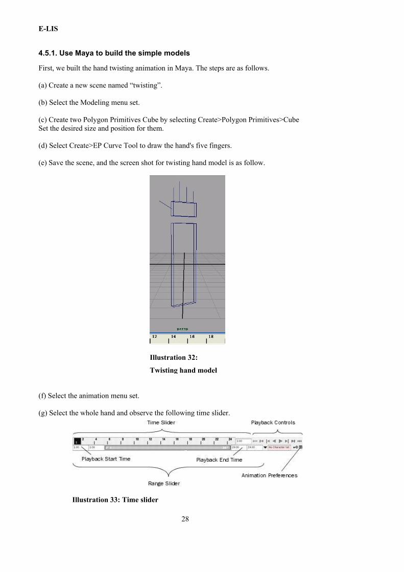
4.5.1. Use Maya to build the simple models
First, we built the hand twisting animation in Maya. The steps are as follows.
(a) Create a new scene named “twisting”.
(b) Select the Modeling menu set.
(c) Create two Polygon Primitives Cube by selecting Create>Polygon Primitives>Cube Set the desired size and position for them.
(d) Select Create>EP Curve Tool to draw the hand's five fingers.
(e) Save the scene, and the screen shot for twisting hand model is as follow.
(f) Select the animation menu set.
(g) Select the whole hand and observe the following time slider.
28
Illustration 32:
Twisting hand model
Illustration 33: Time slider
E-LIS
Set the start time 1,and end time 24.This means one will get 1 second animation at a default playback rate of 24 frames per second.
(h) Go to '1',set the hands as figure 4.52 in the top view, and select Animate > Set Key to set the keyframe there.
Go to “6”, put the hands as figure 4.53,and set the keyframe there.
Go to “12”, put the hands as figure 4.54, and set the keyframe there.
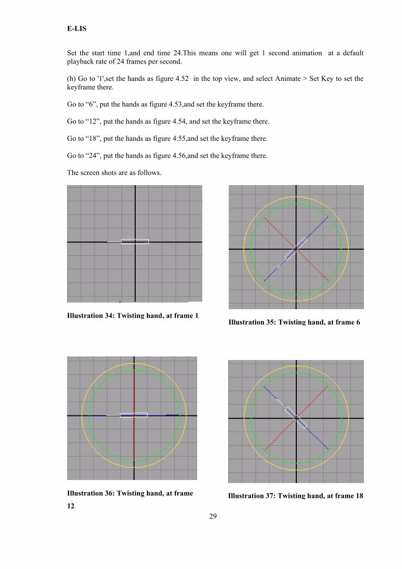
Go to “18”, put the hands as figure 4.55,and set the keyframe there. Go to “24”, put the hands as figure 4.56,and set the keyframe there.
The screen shots are as follows.
29
Illustration 34: Twisting hand, at frame 1Illustration 35: Twisting hand, at frame 6
Illustration 36: Twisting hand, at frame
12 Illustration 37: Twisting hand, at frame 18
E-LIS
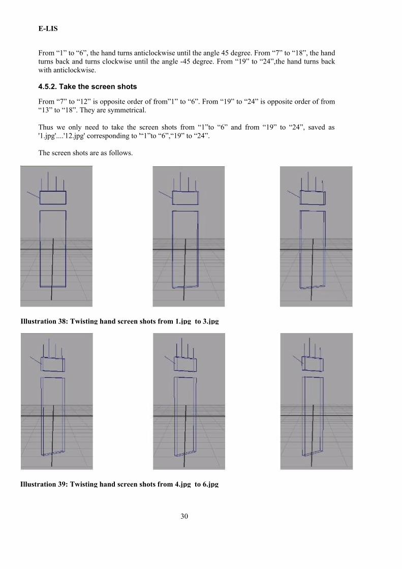
From “1” to “6”, the hand turns anticlockwise until the angle 45 degree. From “7” to “18”, the hand turns back and turns clockwise until the angle -45 degree. From “19” to “24”,the hand turns back with anticlockwise.
4.5.2. Take the screen shots
From “7” to “12” is opposite order of from”1” to “6”. From “19” to “24” is opposite order of from “13” to “18”. They are symmetrical.
Thus we only need to take the screen shots from “1”to “6” and from “19” to “24”, saved as '1.jpg'....'12.jpg' corresponding to '“1”to “6”,“19” to “24”.
The screen shots are as follows.
30
Illustration 38: Twisting hand screen shots from 1.jpg to 3.jpg
Illustration 39: Twisting hand screen shots from 4.jpg to 6.jpg
E-LIS
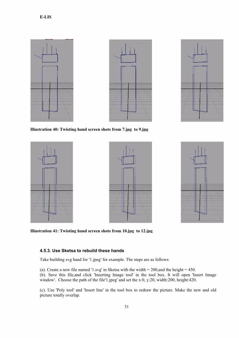
4.5.3. Use Sketsa to rebuild these hands
Take building svg hand for '1.jpeg' for example. The steps are as follows:
(a). Create a new file named '1.svg' in Sketsa with the width = 200,and the height = 450.(b). Save this file,and click 'Inserting Image tool' in the tool box. It will open 'Insert Image window'. Choose the path of the file'1.jpeg' and set the x:0, y:20, width:200, height:420.
(c). Use 'Poly tool' and 'Insert line' in the tool box to redraw the picture. Make the new and old picture totally overlap.
31
Illustration 40: Twisting hand screen shots from 7.jpg to 9.jpg
Illustration 41: Twisting hand screen shots from 10.jpg to 12.jpg
E-LIS
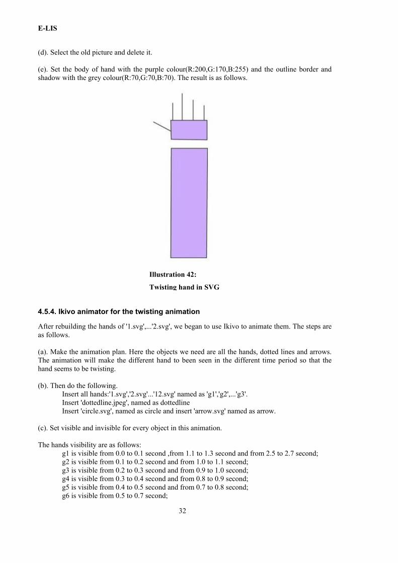
(d). Select the old picture and delete it.
(e). Set the body of hand with the purple colour(R:200,G:170,B:255) and the outline border and shadow with the grey colour(R:70,G:70,B:70). The result is as follows.
4.5.4. Ikivo animator for the twisting animation
After rebuilding the hands of '1.svg',...'2.svg', we began to use Ikivo to animate them. The steps are as follows.
(a). Make the animation plan. Here the objects we need are all the hands, dotted lines and arrows. The animation will make the different hand to been seen in the different time period so that the hand seems to be twisting.
(b). Then do the following.Insert all hands:'1.svg','2.svg'...'12.svg' named as 'g1','g2',...'g3'.Insert 'dottedline.jpeg', named as dottedlineInsert 'circle.svg', named as circle and insert 'arrow.svg' named as arrow.
(c). Set visible and invisible for every object in this animation.
The hands visibility are as follows:g1 is visible from 0.0 to 0.1 second ,from 1.1 to 1.3 second and from 2.5 to 2.7 second; g2 is visible from 0.1 to 0.2 second and from 1.0 to 1.1 second;g3 is visible from 0.2 to 0.3 second and from 0.9 to 1.0 second;g4 is visible from 0.3 to 0.4 second and from 0.8 to 0.9 second;g5 is visible from 0.4 to 0.5 second and from 0.7 to 0.8 second;g6 is visible from 0.5 to 0.7 second;
32
Illustration 42:
Twisting hand in SVG
E-LIS
g7 is visible from 1.3 to 1.4 second and from 2.4 to 2.5 second;g8 is visible from 1.4 to 1.5 second and from 2.3 to 2.4 second;g9 is visible from 1.5 to 1.6 second and from 2.2 to 2.3 second;g10 is visible from 1.6 to 1.7 second and from 2.1 to 2.2 second;g11is visible from 1.7 to 1.8 second and from 2.0 to 2.1 second;g12 is visible from 1.8 to 2.0 second.
Make arrow moving along the circle according to the hand's twisting. Make the circle invisible.
(d). Check the animation and modify. Use the play key to view the animation and modify the hands' position according to preview of the animation.
4.5.5. Modify the twisting animation according to the requirement
After checking my twisting animation, we performed the following modifications.
(1). Remove the arrow.
(2). Adjust the dotted line's length after removing the arrow.
(3). Slow down the twisting.
33

E-LIS
34
E-LIS
Chapter 5. Constraints for hand gestures
5.1. Introduction
This Chapter first discusses two modelings of hand constraints as detailed in section 5.2. Then, section 5.3, section 5.4 and section 5.5 discuss the constraints in H-Animator, SVG animation editors and Maya separately; we also discuss if and how the aforementioned constraint models can been realized in them.
5.2. Constraints for the hand
By observing the hand motion carefully, we found two ways to model constraints on the whole hand.
5.2.1.The method A
The first way is to constrain the range of rotation for every joint in the hand; we called it method A in this thesis.
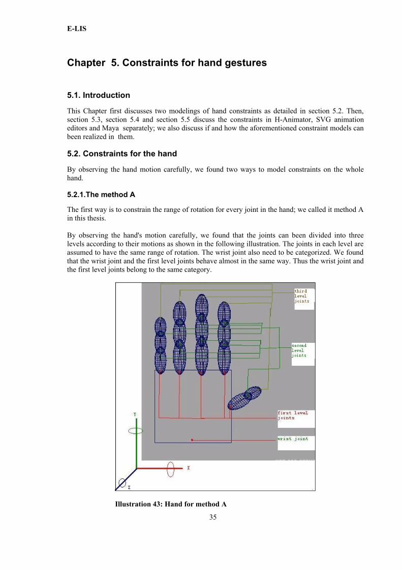
By observing the hand's motion carefully, we found that the joints can been divided into three levels according to their motions as shown in the following illustration. The joints in each level are assumed to have the same range of rotation. The wrist joint also need to be categorized. We found that the wrist joint and the first level joints behave almost in the same way. Thus the wrist joint and the first level joints belong to the same category.
35
Illustration 43: Hand for method A
E-LIS
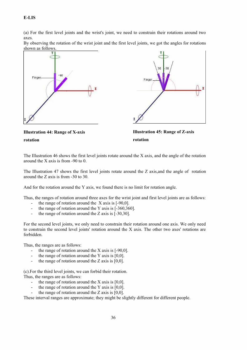
(a) For the first level joints and the wrist's joint, we need to constrain their rotations around two axes. By observing the rotation of the wrist joint and the first level joints, we got the angles for rotations shown as follows.
The Illustration 46 shows the first level joints rotate around the X axis, and the angle of the rotation around the X axis is from -90 to 0.
The Illustration 47 shows the first level joints rotate around the Z axis,and the angle of rotation around the Z axis is from -30 to 30.
And for the rotation around the Y axis, we found there is no limit for rotation angle.
Thus, the ranges of rotation around three axes for the wrist joint and first level joints are as follows: - the range of rotation around the X axis is [-90,0].- the range of rotation around the Y axis is [-360,360].- the range of rotation around the Z axis is [-30,30].
For the second level joints, we only need to constrain their rotation around one axis. We only need to constrain the second level joints' rotation around the X axis. The other two axes' rotations are forbidden.
Thus, the ranges are as follows:- the range of rotation around the X axis is [-90,0].- the range of rotation around the Y axis is [0,0].- the range of rotation around the Z axis is [0,0].
(c).For the third level joints, we can forbid their rotation.Thus, the ranges are as follows:
- the range of rotation around the X axis is [0,0].- the range of rotation around the Y axis is [0,0].- the range of rotation around the Z axis is [0,0].
These interval ranges are approximate; they might be slightly different for different people.
36
Illustration 44: Range of X-axis
rotation
Illustration 45: Range of Z-axis
rotation
E-LIS
5.2.2.The modeling of the method A
Constraint modeling [E1] means representing a problem as a Constraint Satisfaction Problem (CSP), written as Pa := < C ; Dε>, where:
o C is a set of constraints, in our case, C1, C2, C3;o Dε is a set of domain expression, in our case, Dε1, Dε2, Dε3; a domain expression
Dεi is of the form Xi є Di.
In our modeling, domain expressions are as follows:X1, Y1, Z1, X2, Y2, Z2, X3, Y3, Z3 є [-360, 360].
X1, X2, X3 are the variables of rotation around the X axis; Y1, Y2, X3 are the variables of rotation around the Y axis; Z1, Z2, Z3 are the variables of rotation around the Z axis.
Then C1 is the constraint on the rotation of the first level joints and wrist joint, namely:-90<=X1<=0, -30<=Z1<=30.
C2 is the constraint on rotation of the second level joints as follows:-90<=X2<=0, Y2=0, Z2=0;
C3 is the constraint on rotation of the third level joints as follows:X3=0, Y3=0, Z3=0.
Thus Pa := <-90<=X1<=0, -30<=Z1<=30, -90<=X2<=0, Y2=0, Z2=0, X3=0, Y3=0, Z3=0;
X1, Y1, Z1, X2, Y2, Z2, X3, Y3, Z3 є [-360, 360]>
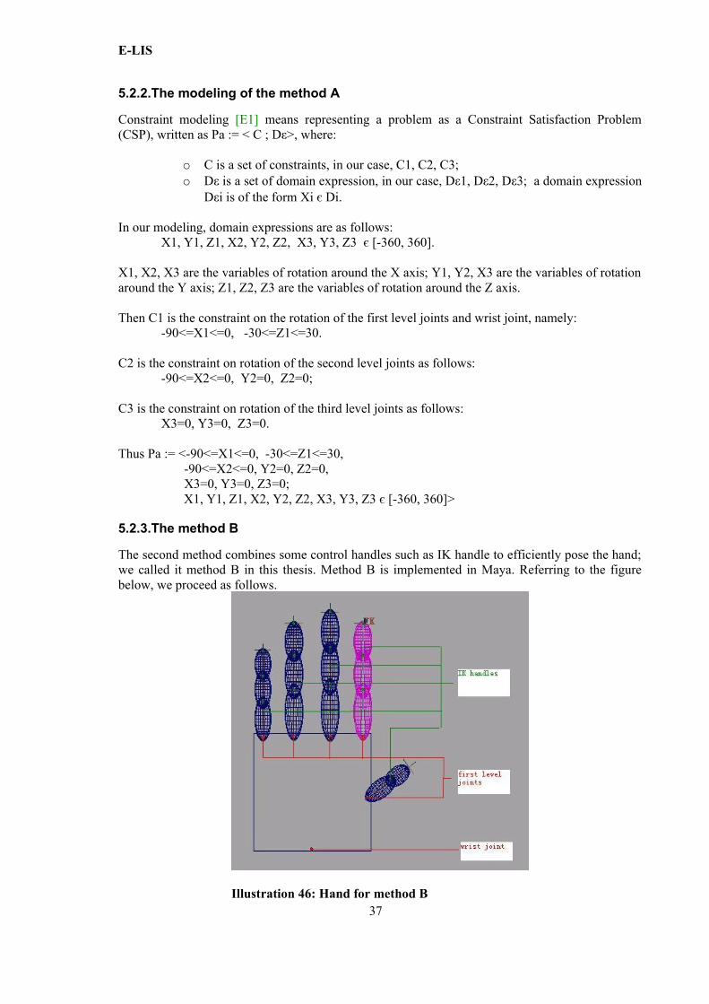
5.2.3.The method B
The second method combines some control handles such as IK handle to efficiently pose the hand; we called it method B in this thesis. Method B is implemented in Maya. Referring to the figure below, we proceed as follows.
37Illustration 46: Hand for method B
E-LIS
(a) For the wrist joint, we need to constrain the rotations around two axes just like (a) in method A.Thus the ranges of three axes rotation for the wrist joint are as follows:
- the range of rotation around X is [-90,0].- the range of rotation around Y is [-360,360].- the range of rotation around Z is [-30,30].
(b) For the first level joints we only need to constrain the rotation around one axis. Why we only need to constrain only a rotation around one axis? Because when we use the IK handle, which was discussed in Section 4.4.4.4, the first level joints can rotate automatically following the fingertip's movement.
But we still need to constrain the rotation around an axis so that the finger will not bend into the palm as we have already shown in Section 4.4.4.6. Thus the ranges are as follows:
- the range of rotation around X is [-90,0];- the range of rotation around Y is [-360,360];- the range of rotation around Z is [-360,360].
(c) For the remaining joints we let IK handle to control the fingertip's motion. And we only need to constrain the range of the fingertip's position.
This part will be discussed in details in Section 5.5.3. The number we get there are as follows: X є [0, 12.67], Y є [-11.74, 8.54], Z є [-3, 3];
X, Y, Z are the coordinates of the fingertips.
5.2.4.The modeling of the method B
We tried to model the above problem as a CSP, Pb.
C1 is the constraint on rotation of wrist joint as follows:-90<=X1<=0, -30<=Z1<=30X1 is the variable of rotation around the X-axis.Z1 is the variable of rotation around the Z-axis.
C2 is the constraint on rotation of the first level joints as follows:-90<=X2<=0X2 is the variable of rotation around the X-axis.
C3 is the constraint on range of the fingertip's coordinate as follows:0<=X3 <=12.67, -11.74<=Y3 <=8.54, -3 <=Z <=3X3, Y3, Z3 are the variables of the fingertip's coordinates.
Dε is as follows:X1, Y1, Z1, X2, Y2, Z2 є [-360, 360], X3, Y3, Z3 є R.
Thus Pb := <-90<=X1<=0, -30<=Z1<=30, -90<=X2<=0, 0<=X3 <=12.67, -11.74<=Y3 <=8.54, -3 <=Z3 <=3;
X1,Y1,Z1, X2, Y2, Z2 є [-360, 360], X3, Y3, Z3 є R >.
The method A can pose the finger in more accurate way than the method B. Thus method A can been chosen when high accuracy is required. But method A is rather time consuming in both modeling and posing the hand. It sacrifices the time for accuracy.
38
E-LIS
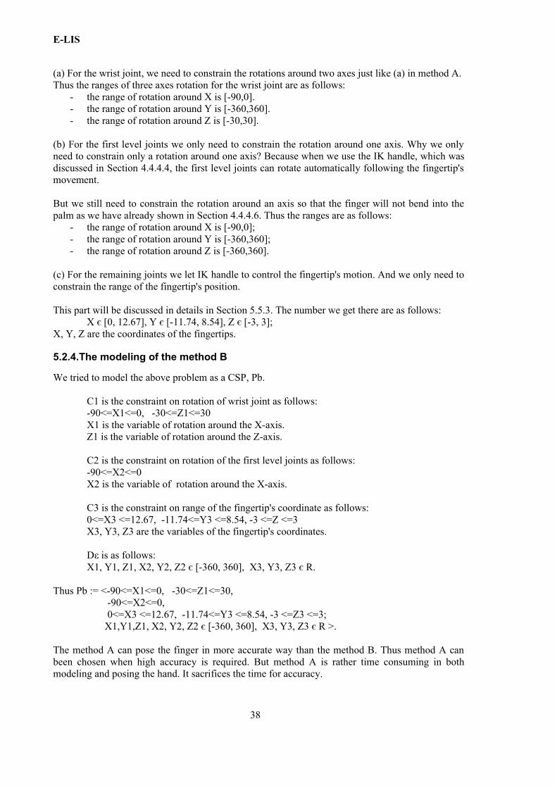
5.2.5. Constraints for avoiding the fingers from flying away
We still miss some constraints to avoid fingers from flying away. To solve this problem, we need to fix the distance between two joints (see the following figure).
We fixed the distance between each group of joints as follows: - the distance between the first group of joints and the second group of joints is 2.5;- the distance between the second group of joints and third group of joints is 2;- the distance between the third group of joints and the fourth group of joints is 1.5.
The corresponding constraints are as follows( (X2 – X1)2 + (Y2 – Y1)2 + (Z2 – Z1)2 )1/2 = 2.5,( (X3 – X2)2 + (Y3 – Y2)2 + (Z3 – Z2)2 )1/2 = 2,( (X4 – X3)2 + (Y4 – Y3)2 + (Z4 – Z3)2 )1/2 = 1.5,
where Xi ,Yi , Zi are the coordinates of the i-th group of joints (i є [1,4]).
Dε is Xi , Yi ,Zi є R, i є [1,4].
Thus the CSP is is < ( (X2 – X1)2 + (Y2 – Y1)2 + (Z2 – Z1)2 )1/2 = 2.5,( (X3 – X2)2 + (Y3 – Y2)2 + (Z3 – Z2)2 )1/2 = 2 ,( (X4 – X3)2 + (Y4 – Y3)2 + (Z4 – Z3)2 )1/2 = 1.5; Xi , Yi ,Zi є R, i є [1,4]>.
39
Illustration 47: Hand 3
E-LIS
5.3. Constraints in H-Animator
Which kinds of constraints does H-Animator have? H-Animator has some kinds of constraints such as 'Mirror L2R' button, reusing existing animations to build complex animations. 'Mirror L2R' button is a button that allows one to mirror the values for the left joints to the right ones. Thus 'Mirror L2R' button constrains the mirroring of the joints.
However H-Animator still lacks facilities for modeling the constraints for hand gestures we described above. We discuss this in the following.
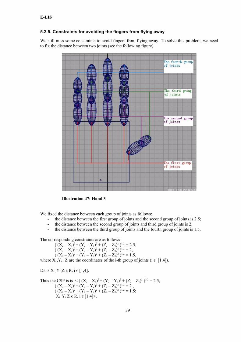
The rotation angles of the finger's joints can be any, but in the physical world this is not true. There should be facilities for modeling and constraining the angle of the joint's rotation. See the following screen shot. The angle between the middle finger and the index finger is not acute, as instead is “in reality”.
The second constraint H-Animator does not allow one to model is the constraint on the distance between joints. Without this, the finger may fly out unexpectedly when one rotates the finger as shown in the following screen shots.
40
Illustration 48: Finger rotates in wrong way
E-LIS
Therefore neither the A modeling nor the B modeling can be implemented in H-Animator.
5.4. Constraints in SVG animation editors
SVG animation editors have some constraint facilities that allow one to set the control points on the trajectory of the object's movement. However an SVG animation editor such as Ikivo has even less constraints on implementing hand gestures' animation than H-Animator. There is no way of implementing 2D constraints for the hands, limited to the real plane.
41
Illustration 49: Finger flies out
Illustration 50: Finger flies out for one hand
E-LIS
5.5. Constraints in Maya
Maya has many facilities which can been used to constrain hand gestures. We explain some of these facilities using finger bending, introduced in Chapter 4, as an example.
5.5.1. Take finger bending animation for example.
I try to model finger bending problem as a CSP,which means Constraint satisfaction problems,P := < C ; Dε>
C is a set of constraints:C1,C2. Dε is a set of domain expression: Dε1, Dε2.domain expression is the expression Dεi : Xi є Di.(i є [1,2])Xi is the variable in Ci.Di is the domain of variable Xi.
Thus the CSP also can been written as P := < C1, C2 ; Dε1, Dε2 >
C1 is the constraint on rotation of the first joint, which is been clicked first in figure 5.9.Dε1 is the domain expression of C1.C2 is the constraint on the range of the fingertip's coordinates.Dε2 is the domain expression of C2.
What C1 and C2 formally are is explained below. The modeling of finger bending problem corresponds to the modeling of method B. The only difference is we do not need the constraint for wrist joint here.
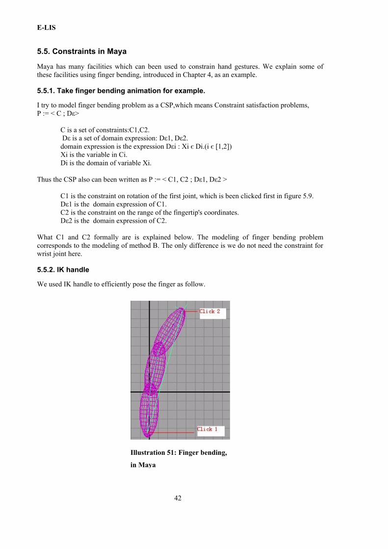
5.5.2. IK handle
We used IK handle to efficiently pose the finger as follow.
42
Illustration 51: Finger bending,
in Maya
E-LIS
Click the first joint and then click the last joint as shown above; the IK handle will be applied to these joints. And then we can use a control point to constrain on the range of the fingertip's movement.
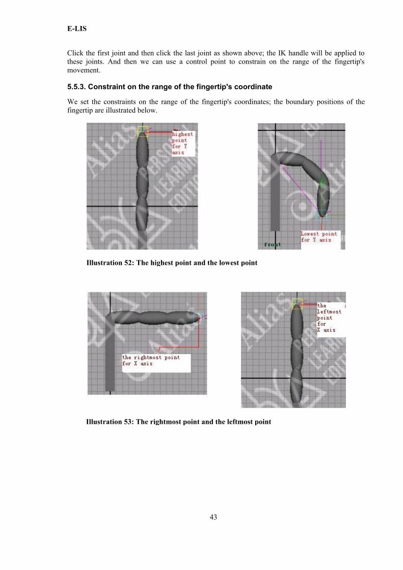
5.5.3. Constraint on the range of the fingertip's coordinate
We set the constraints on the range of the fingertip's coordinates; the boundary positions of the fingertip are illustrated below.
43
Illustration 53: The rightmost point and the leftmost point
Illustration 52: The highest point and the lowest point
E-LIS
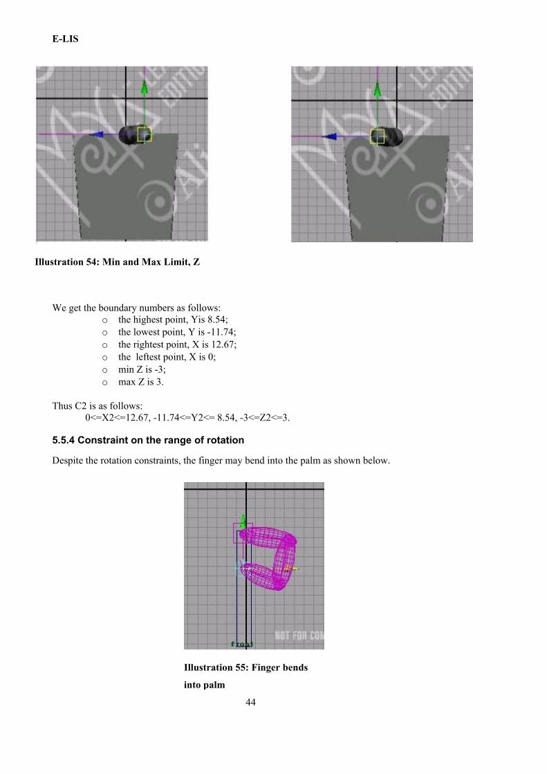
We get the boundary numbers as follows:o the highest point, Yis 8.54;o the lowest point, Y is -11.74;o the rightest point, X is 12.67;o the leftest point, X is 0;o min Z is -3;o max Z is 3.
Thus C2 is as follows:0<=X2<=12.67, -11.74<=Y2<= 8.54, -3<=Z2<=3.
5.5.4 Constraint on the range of rotation
Despite the rotation constraints, the finger may bend into the palm as shown below.
44
Illustration 54: Min and Max Limit, Z
Illustration 55: Finger bends
into palm
E-LIS
Because the leftmost point is X = 0, the finger can continue going left until it reaches X=0. Thus only the constraint on the range of the fingertip's movement is not sufficient. We need also to constrain the range of the finger's rotation, particularly constraining the range of the rotation along Z for joint1, as follows:
Min Rot Limit X is -90; Max Rot Limit X is 0.
Thus C1 is as follows:-90<=X1<= 0.
P := < -90<=X1<= 0,0<=X2<=12.67, -11.74<=Y2<= 8.54, -3<=Z2<=3; X1, Y1, Z1 є [-360, 360], X3, Y3, Z3 є R>
Now, can the methods A and B be realized in Maya? Can we avoid fingers from flying away?
- Method A can been realized by setting the limit for rotation of the joints.- Method B can been realized by firstly using IK handle and setting the limit for the
fingertip's.- In Maya we can also avoiding fingers from flying away by locking the translate attributes
for corresponding joints.
Thus the constraints on the whole hand discussed in section 5.2 can been totally realized in Maya.
The following screen shots show the hand closing animation, realized with method B and the constraints for avoiding the fingers from flying away.
45
Illustration 56: Hand
closing animation-1
Illustration 57: Hand closing
animation-2

E-LIS
46
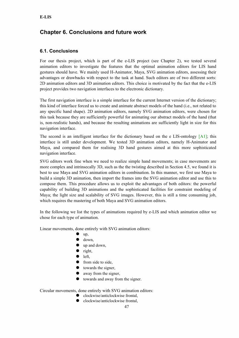
E-LIS
Chapter 6. Conclusions and future work
6.1. Conclusions
For our thesis project, which is part of the e-LIS project (see Chapter 2), we tested several animation editors to investigate the features that the optimal animation editors for LIS hand gestures should have. We mainly used H-Animator, Maya, SVG animation editors, assessing their advantages or drawbacks with respect to the task at hand. Such editors are of two different sorts: 2D animation editors and 3D animation editors. This choice is motivated by the fact that the e-LIS project provides two navigation interfaces to the electronic dictionary.
The first navigation interface is a simple interface for the current Internet version of the dictionary; this kind of interface forced us to create and animate abstract models of the hand (i.e., not related to any specific hand shape). 2D animation editors, namely SVG animation editors, were chosen for this task because they are sufficiently powerful for animating our abstract models of the hand (that is, non-realistic hands), and because the resulting animations are sufficiently light in size for this navigation interface.
The second is an intelligent interface for the dictionary based on the e LIS-ontology [A1]; this interface is still under development. We tested 3D animation editors, namely H-Animator and Maya, and compared them for realising 3D hand gestures aimed at this more sophisticated navigation interface.
SVG editors work fine when we need to realize simple hand movements; in case movements are more complex and intrinsecally 3D, such as the the twisting described in Section 4.5, we found it is best to use Maya and SVG animation editors in combination. In this manner, we first use Maya to build a simple 3D animation, then import the frames into the SVG animation editor and use this to compose them. This procedure allows us to exploit the advantages of both editors: the powerful capability of building 3D animations and the sophisticated facilities for constraint modeling of Maya; the light size and scalability of SVG images. However, this is still a time consuming job, which requires the mastering of both Maya and SVG animation editors.
In the following we list the types of animations required by e-LIS and which animation editor we chose for each type of animation.
Linear movements, done entirely with SVG animation editors:● up,● down,● up and down,● right,● left,● from side to side,● towards the signer,● away from the signer,● towards and away from the signer.
Circular movements, done entirely with SVG animation editors:● clockwise/anticlockwise frontal,● clockwise/anticlockwise frontal,
47
E-LIS
● clockwise/anticlockwise horizontal.
Twisting movents, realized using Maya and SVG animation editors:● convex anticlockwise vertical,● concave anticlockwise vertical,● concave clockwise vertical.
The following hand animation were only implemented in Maya because of time limits; they are expected to be implement also in SVG in the future.
● wrist bending forwards,● wrist bending backwards,● wrist bending sideways,● finger bending at the palm knuckles,● finger bending at knuckles,● closing hand or fingers,● opening hand or fingers,● wavelike movement,● hands towards each other,● hands away from each other,● crossing hands,● hands interlinking,● hand insertion,● change place of hands.
For the second part, we tried to model the hand constraints and found two modelings of hand constraints. We also used them when we built our 3D animations in Maya (e.g., we used the so-called B method for the implementation of closing hands, and we used the so-called A method for the implementation of interlinking hands).
6.2. Benefits of our work
For the goals of e-LIS it is relevant to have a visual editor for drawing and animating hand gestures in a simple and ‘light’ manner; the editor should allow for the definition of primitive components (i.e., the so-called building blocks of the animation), of spatial constraints (e.g., the left and right hands should move symmetrically), and temporal constraints (e.g., speed of movements).
In this respect, our thesis work brings the following benefits to the e-LIS project:- we found a way to combine Maya and SVG animation editors to speed up the composition
of LIS hand animations;- we modeled hand constraints as ‘abstract’ constraint problems,- we assessed how the surveyed editors allow us to implement such constraints,- we implemented the required hand animations for e-LIS using our constraint models (see
Chapter 5).
The constraint-based approach spares users from tedious repetitive manual tasks and allows them to focus on the relevant features of LIS signs. Thus LIS experts, computer scientists interested in the development of human interfaces and the readers interested in hand gesture animation may all benefit from the findings of this thesis.
48
E-LIS
6.3. Future work
Maya allows for the definition of primitive components and spatial constraints. However, we cannot realize the temporal constraints in any of the editors we used. If it is required to change the speed of movements, we need to set all the keys again every time. This issue might be improved in the future.
For the e-LIS project, there are two navigation interfaces (see Chapter 2). The first navigation interface is almost finished but the second navigation is still under development. For the second interface, which requires many realistic 3D hand images, a constraint-based editor with the above characteristics will be the ‘must’.
As for the more technical details concerning the implementation of animations, several questions remain open for future investigation. We list some of them as follows.
- How to export Maya files as SVG files, so that time is not wasted in rebuilding Maya animations in SVG format?
- Can we improve the existing SVG editors with basic facilities, such as the eraser tool, and constraint facilities, such as imposing symmetric movements?
- How to realize an animation editor capable of combining the advantages of Maya and SVG animation editors, maintaining the simplicity of use of the latter?
49

E-LIS
50
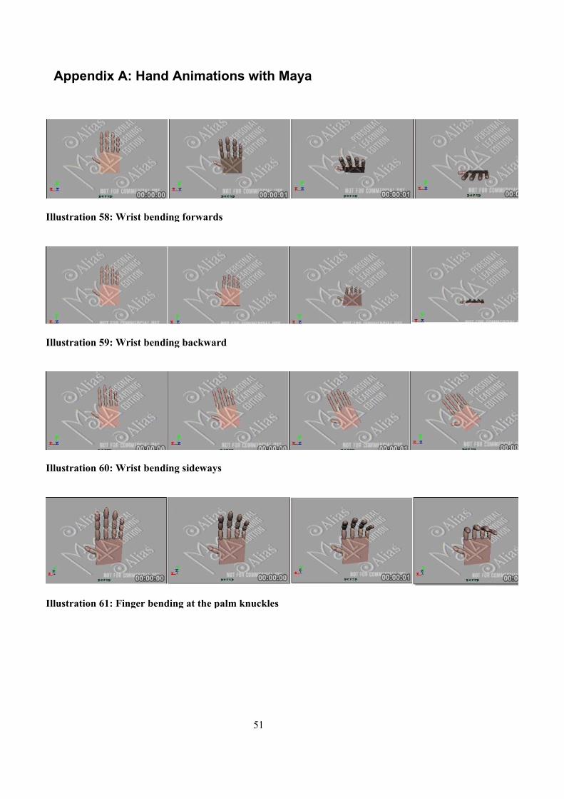
Appendix A: Hand Animations with Maya
51
Illustration 58: Wrist bending forwards
Illustration 59: Wrist bending backward
Illustration 60: Wrist bending sideways
Illustration 61: Finger bending at the palm knuckles
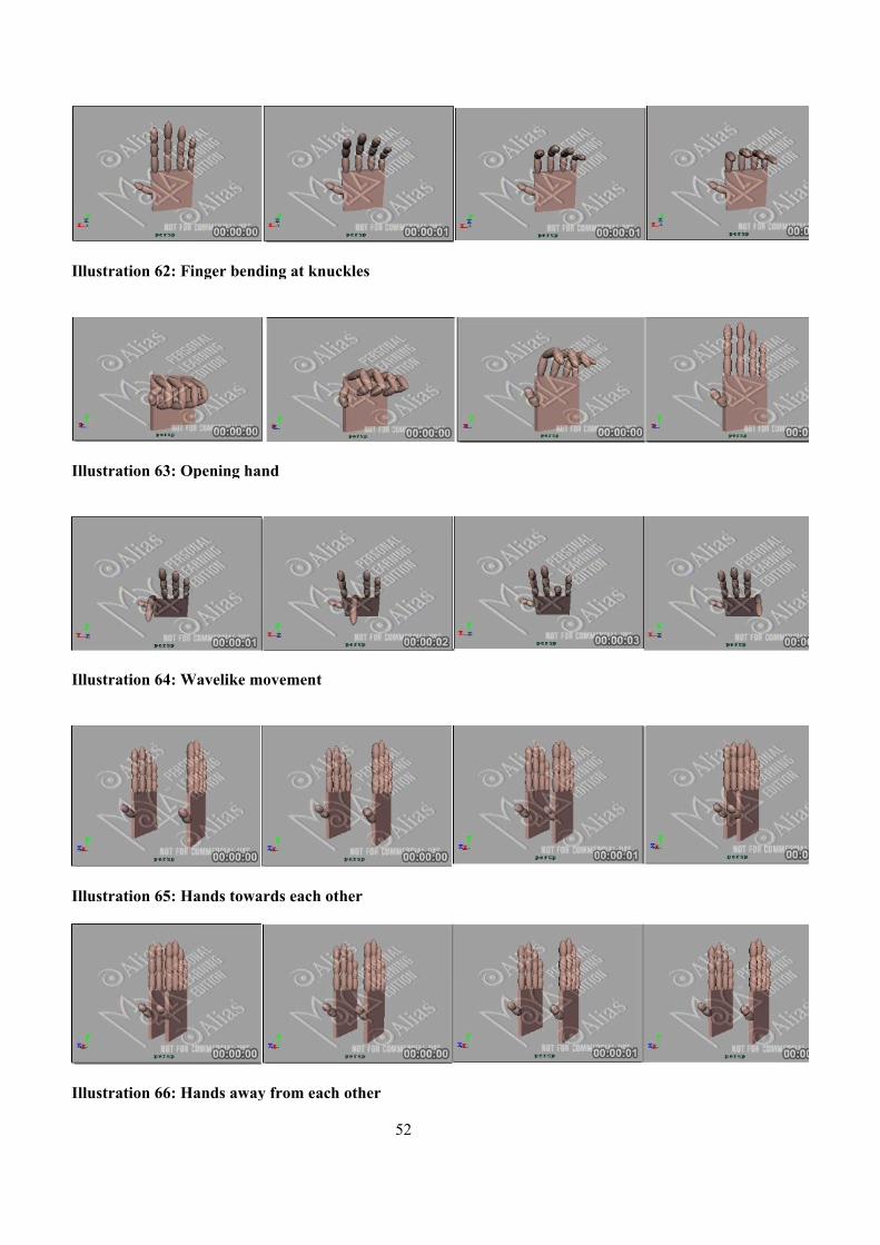
52
Illustration 62: Finger bending at knuckles
Illustration 63: Opening hand
Illustration 64: Wavelike movement
Illustration 65: Hands towards each other
Illustration 66: Hands away from each other
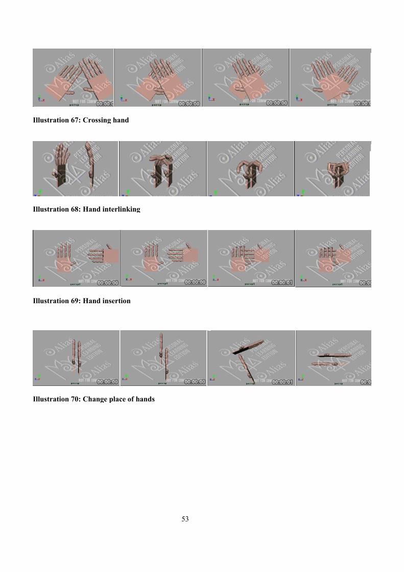
53
Illustration 67: Crossing hand
Illustration 70: Change place of hands
Illustration 68: Hand interlinking
Illustration 69: Hand insertion

54
Bibliography
[A1] Monika Tomkowicz. Electronic Dictionary of Italian Sign Language. Bozen-Bolzano Free University. July 21, 2006.
[C1] Web 3D Consortium. What is X3D? URL: http://www.web3d.org/. Last visit: September 2006.
[C2] 2006 HCI Lab, University of Udine. H-Animator (version 0.2). URL:http://hcilab.uniud.it/hanimator/ . Last visit: September 2006.
[C3] Alias Systems Corporation. Tutorials and Learning Tools. URL: http://localhost:4451/Maya7.0PLE/en_US/index.html?tutorials.Last visit: September 2006.
[C4] Alias Systems Corporation. About Maya Personal Learning Edition. URL: http://localhost:4451/Maya7.0PLE/en_US/index.html?tutorials.Last visit: September 2006.
[C5] Liz Fulghum. Vector vs. Bitmap Graphics - an Introductory Guide for Clients and Designers.URL: http://www.eastbywest.com/pub/vectorbitmap/. Last visit: September 2006.
[C6] W3C: Accessibility Features of SVG. URL: http://www.w3.org/TR/SVG-access/#WhatLast visit: September 2006.
[C7] Catto Creations.Learning SVG. URL: http://www.cattocreations.com/LearnSVG/Help.html. Last visit: September 2006.
[C8] SVG Wiki. Design Tools. URL: http://wiki.svg.org/Design_Tools Last visit:September 2006.
[C9] Sun. Get Java. URL: http://www.java.com/getjava. Last visit: September 2006.
[C10] SVG Viewer Plugin Installation. URL: http://sdx.archivesdefrance.culture.gouv.fr/gpl/navimages/en/svgViewer.html .Last visit: September 2006.
[C11] Buttussi F., Chittaro L., Nadalutti D. H-Animator: A Visual Tool for Modeling, Reuse and Sharing of X3D Humanoid Animations. Proceedings of Web3D 2006: 11th International Conference on 3D Web Technology, ACM Press, New York, pp. 109-117. April 2006.
[E1] Krzysztof R.Apt. Principles of Constraint Programming. Cambridge University Press. 2003.
55