angelica perez-andujar university of puerto rico, mayagüez campus
DESCRIPTION
Fermi National Accelerator Laboratory Neutron Therapy Facility. Experimental Analysis of Wedge Factors for Neutron Therapy. Angelica Perez-Andujar University of Puerto Rico, Mayagüez Campus. Outline. NEUTRON THERAPY AND TREATMENT PLANNING THE USE OF TEFLON WEDGE FILTERS - PowerPoint PPT PresentationTRANSCRIPT

Angelica Perez-AndujarUniversity of Puerto Rico, Mayagüez Campus
Fermi National Accelerator LaboratoryNeutron Therapy Facility
Experimental Analysis of Wedge Factors for Neutron Therapy

Outline
NEUTRON THERAPY AND TREATMENT PLANNING
THE USE OF TEFLON WEDGE FILTERS
WEDGE FACTOR MEASUREMENTS
RESULTS
CONCLUSION
RECOMMENDATIONS

Dose Distribution
An isodose chart presents the percent of dose that is going to be delivered at an specific depth at the body.
The dose distribution is presented as isodose curves.

Teflon Wedge Filter

Wedge Effect on the Isodose Curves
Wedges tilts the isodose curves.
no wedge 45º wedge 60 º wedge

Wedges Characteristics
Wedge Isodose tilt Angle
(º)
Height(cm)
Width(cm)
Length(cm)
Physical Wedge angle
(º)
1 45 5.3 8.9 17.2 31
2 45 8.9 15.0 17.5 31
3 60 10.2 10.2 10.2 45
4 60 15.2 15.2 15.2 45
h
wl
Teflon wedge filter without aluminum mount
Each wedge has a physical angle that tilts the dose that the patient is going to received.

More about Wedge Filters
They absorb some beam
What other changes can wedges produce?
What can be done to ensure the delivery of the correct amount of dose?
A wedge factor could be calculated.
What is a wedge factor?
The wedge factor is the ratio of the dose delivered with and without wedge.
If the wedge factor is known it is possible to calculate the amount of beam necessary to deliver the desired dose.

Experimental Setup
Linac Protons
BerylliumTarget
Heavy ConcreteShielding WallNeutrons
SDD= 109cm SAD=190cm
Collimator
Transmission Chamber
Isoplane
Isocenter
Polyethylene Phantom

Ionization Chamber in the Phantom
Spokas Thimble Chamber

Collimators

Wedges and Collimators Used
Wedge Collimators used (cm x cm)
1(45º)
3x3, 4x4, 6x6, 8x8, 10x10, 12x12, 14x14
2(45º)
10x10, 12x12, 14x14, 16x16, 18x18, 20x20, 24x24
3(60º)
3x3, 4x4, 6x6, 8x8, 10x10, 12x12, 14x14
4(60º)
10x10, 12x12, 14x14, 16x16, 18x18, 20x20, 24x24
Not all wedges were used for all collimators.
Wedges 1 and 3 do not cover the big collimator aperture.
Wedge 2 and 4 absorb more beam than necessary when small collimators are used.

Wedge Factor Calculations
Wedge Factor =
(Normalized Charge x TPCOR) wedge
(Normalized Charge x TPCOR )no wedge
The wedge factors obtained were compared with the ones that were calculated years ago
The amount of charge received by the ionization chamber at the phantom was normalized to the one received at the transmission chamber.
The normalized charge is multiplied by a temperature-pressure correction factor.
TPCOR=T + 273.15
295.15x 1013.25
P
The wedge factor is given by:

Wedge Factor vs. Depth Wedge Factor vs. Depth (3 cm x 3 cm collimator)
0.5
0.55
0.6
0.65
0.7
0.75
0.8
0 5 10 15 20 25 30
Depth (cm)
Wed
ge F
acto
r
wedge 1 measured
wedge 1 calculated
wedge 3 measured
wedge 3 calculated
Wedge Factor vs. Depth(24 cm x 24 cm collimator)
0.4
0.45
0.5
0.55
0.6
0.65
0.7
0 5 10 15 20 25 30
Depth (cm)
We
dg
e F
ac
tor
wedge 2 measured
wedge 2 calculated
wedge 4 measured
wedge 4 calculated
Wedge Factor vs. Depth(10 cm x 10 cm collimator)
0.4
0.45
0.5
0.55
0.6
0.65
0.7
0.75
0.8
0 5 10 15 20 25 30
Depth (cm)
Wed
ge F
acto
r
wedge 1 measured
wedge 1 calculated
wedge 2 measured
wedge 2 calculated
wedge 3 measured
wedge 3 calculated
wedge 4 measured
wedge 4 calculated
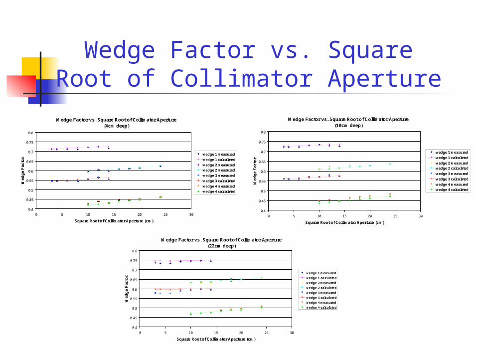
Wedge Factor vs. Square Root of Collimator Aperture
Wedge Factor vs. Square Root of Collimator Aperture(4cm deep)
0.4
0.45
0.5
0.55
0.6
0.65
0.7
0.75
0.8
0 5 10 15 20 25 30
Square Root of Collimator Aperture (cm)
Wed
ge
Fac
tor
wedge 1 measured
wedge 1 calculated
wedge 2 measured
wedge 2 measured
wedge 3 measured
wedge 3 calculated
wedge 4 measured
wedge 4 calculated
Wedge Factor vs. Square Root of Collimator Aperture(10cm deep)
0.4
0.45
0.5
0.55
0.6
0.65
0.7
0.75
0.8
0 5 10 15 20 25 30
Square Root of Collimator Aperture (cm)
Wed
ge
Fac
tor
wedge 1 measured
wedge 1 calculated
wedge 2 measured
wedge 2 calculated
wedge 3 measured
wedge 3 calculated
wedge 4 measured
wedge 4 calculated
Wedge Factor vs. Square Root of Collimator Aperture(22cm deep)
0.4
0.45
0.5
0.55
0.6
0.65
0.7
0.75
0.8
0 5 10 15 20 25 30
Square Root of Collimator Aperture (cm)
Wed
ge
Fac
tor
wedge 1 measured
wedge 1 calculated
wedge 2 measured
wedge 2 calculated
wedge 3 measured
wedge 3 calculated
wedge 4 measured
wedge 4 calculated

Conclusions and Recommendations
The wedge factor is a function of the collimator size and the depth in the phantom.
It increases as depth and collimator size increase. The relationship between depth and collimator size is not linear
it suggests a curvature as depth increases.
Conclusions
Recommendations New measurements have to be made. It is necessary to use a tissue equivalent material phantom. Measurements need to be performed with longer beam exposure. An improved phantom positioning system should be developed.

Acknowledgements
Thomas Kroc Arlene Lennox Gordon Holmblad Ruth DeJerld Marc Austin Miguel Morales All my new friends SIST Program you

Questions ?