an/fpn-63(v)precision approach radar …v)precision approach radar (par) life cycle extension...
TRANSCRIPT

AN/FPN-63(V)PRECISION APPROACH
RADAR (PAR) Life Cycle Extension STATEMENT OF WORK
Dated 13 Sep 2012
1
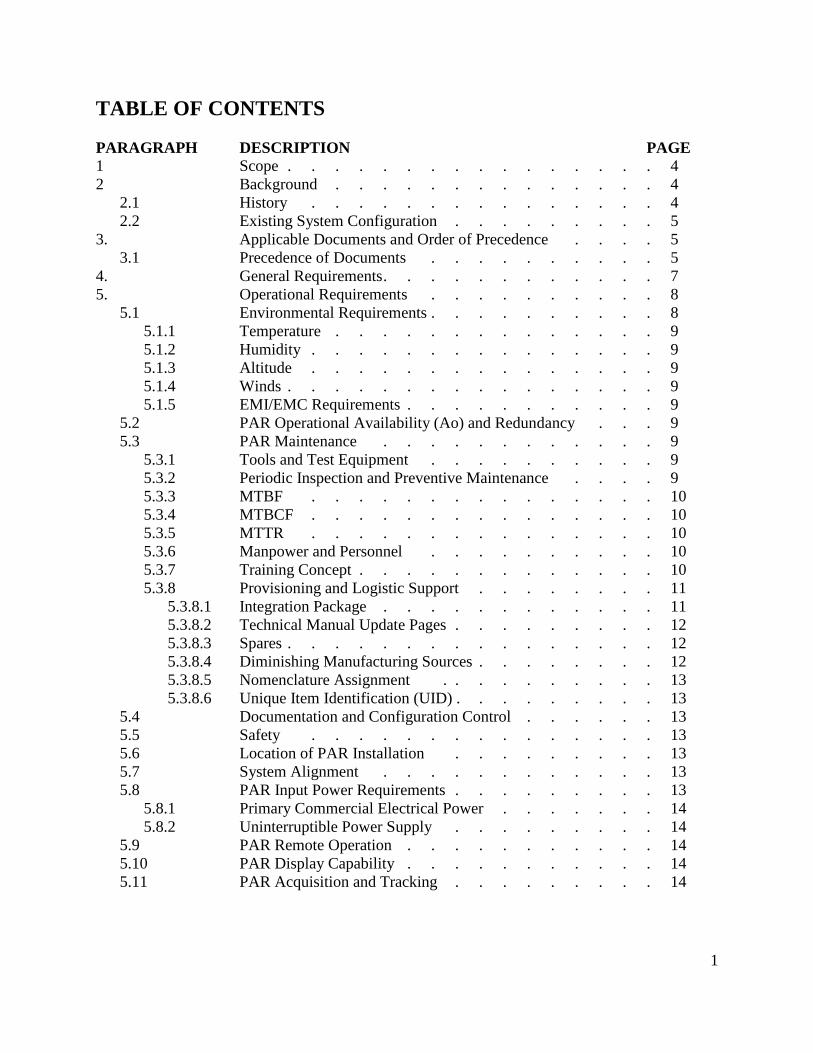
TABLE OF CONTENTS
PARAGRAPH DESCRIPTION PAGE
1 Scope . . . . . . . . . . . . . . . . 4
2 Background . . . . . . . . . . . . . . 4
2.1 History . . . . . . . . . . . . . . . 4
2.2 Existing System Configuration . . . . . . . . . 5
3. Applicable Documents and Order of Precedence . . . . 5
3.1 Precedence of Documents . . . . . . . . . . 5
4. General Requirements . . . . . . . . . . . . 7
5. Operational Requirements . . . . . . . . . . 8
5.1 Environmental Requirements . . . . . . . . . . 8
5.1.1 Temperature . . . . . . . . . . . . . . 9
5.1.2 Humidity . . . . . . . . . . . . . . . 9
5.1.3 Altitude . . . . . . . . . . . . . . . 9
5.1.4 Winds . . . . . . . . . . . . . . . . 9
5.1.5 EMI/EMC Requirements . . . . . . . . . . . 9
5.2 PAR Operational Availability (Ao) and Redundancy . . . 9
5.3 PAR Maintenance . . . . . . . . . . . . 9
5.3.1 Tools and Test Equipment . . . . . . . . . . 9
5.3.2 Periodic Inspection and Preventive Maintenance . . . . 9
5.3.3 MTBF . . . . . . . . . . . . . . . 10
5.3.4 MTBCF . . . . . . . . . . . . . . . 10
5.3.5 MTTR . . . . . . . . . . . . . . . 10
5.3.6 Manpower and Personnel . . . . . . . . . . 10
5.3.7 Training Concept . . . . . . . . . . . . . 10
5.3.8 Provisioning and Logistic Support . . . . . . . . 11
5.3.8.1 Integration Package . . . . . . . . . . . . 11
5.3.8.2 Technical Manual Update Pages . . . . . . . . . 12
5.3.8.3 Spares . . . . . . . . . . . . . . . . 12
5.3.8.4 Diminishing Manufacturing Sources . . . . . . . . 12
5.3.8.5 Nomenclature Assignment . . . . . . . . . . 13
5.3.8.6 Unique Item Identification (UID) . . . . . . . . . 13
5.4 Documentation and Configuration Control . . . . . . 13
5.5 Safety . . . . . . . . . . . . . . . 13
5.6 Location of PAR Installation . . . . . . . . . 13
5.7 System Alignment . . . . . . . . . . . . 13
5.8 PAR Input Power Requirements . . . . . . . . . 13
5.8.1 Primary Commercial Electrical Power . . . . . . . 14
5.8.2 Uninterruptible Power Supply . . . . . . . . . 14
5.9 PAR Remote Operation . . . . . . . . . . . 14
5.10 PAR Display Capability . . . . . . . . . . . 14
5.11 PAR Acquisition and Tracking . . . . . . . . . 14

2
PARAGRAPH DESCRIPTION PAGE
5.11.1 Tracking in Clear Weather . . . . . . . . . . 15
5.11.2 Tracking in Rain Clutter Environment . . . . . . . 15
5.11.3 Overall System MTI/MTD Performance . . . . . . . 15
5.12 PAR Response Time and Update Rate . . . . . . . 15
5.13 PAR Coverage . . . . . . . . . . . . . 15
5.14 PAR Antenna Control . . . . . . . . . . . 16
5.15 PAR Range Accuracy . . . . . . . . . . . . 16
5.16 PAR Elevation Angular Accuracy . . . . . . . . 16
5.17 PAR Azimuth Angular Accuracy . . . . . . . . . 16
5.18 PAR Target Separation/Resolution . . . . . . . . 16
5.19 Runway Coverage . . . . . . . . . . . . . 16
5.20 Frequency Range . . . . . . . . . . . . . 17
5.21 Fault Isolation Capabilities . . . . . . . . . . 17
5.22 PAR Training Device . . . . . . . . . . . . 17
5.23 System Software . . . . . . . . . . . . . 17
5.23.1 Information Assurance . . . . . . . . . . . 17
5.23.1.1 Requirements . . . . . . . . . . . . . . 17
5.23.1.2 Accreditation Documentation . . . . . . . . . . 17
5.23.1.3 Accreditation Assessment . . . . . . . . . . . 18
5.24 Software Maintenance Package . . . . . . . . . 18
6. Subassembly Specifications . . . . . . . . . . 18
6.1 Antennas . . . . . . . . . . . . . . . 18
6.1.1 Azimuth Antenna . . . . . . . . . . . . . 18
6.1.2 Elevation Antenna . . . . . . . . . . . . 19
6.2 Transmitter . . . . . . . . . . . . . . 19
6.3 Receiver . . . . . . . . . . . . . . . 19
6.4 Display Console . . . . . . . . . . . . . 19
6.5 Processor. . . . . . . . . . . . . . . . 20
7. PAR LCE SETR Events . . . . . . . . . . . 20
7.1 Post Award Kick-Off Meeting . . . . . . . . . 20
7.2 Preliminary Design Review . . . . . . . . . . 20
7.2.1 Purpose . . . . . . . . . . . . . . . 20
7.2.2 Timing . . . . . . . . . . . . . . . . 21
7.2.3 Required Outputs . . . . . . . . . . . . . 21
7.3 Critical Design Review . . . . . . . . . . . 21
7.3.1 Purpose . . . . . . . . . . . . . . . 21
7.3.2 Timing . . . . . . . . . . . . . . . . 21
7.3.3 Required Outputs . . . . . . . . . . . . . 22
7.4 Test Readiness Review . . . . . . . . . . . 22
7.4.1 Purpose . . . . . . . . . . . . . . . 22
7.4.2 Timing . . . . . . . . . . . . . . . . 22
7.4.3 Required Outputs . . . . . . . . . . . . . 22
7.5 Production Readiness Review . . . . . . . . . . 22
7.5.1 Purpose . . . . . . . . . . . . . . . 22
3
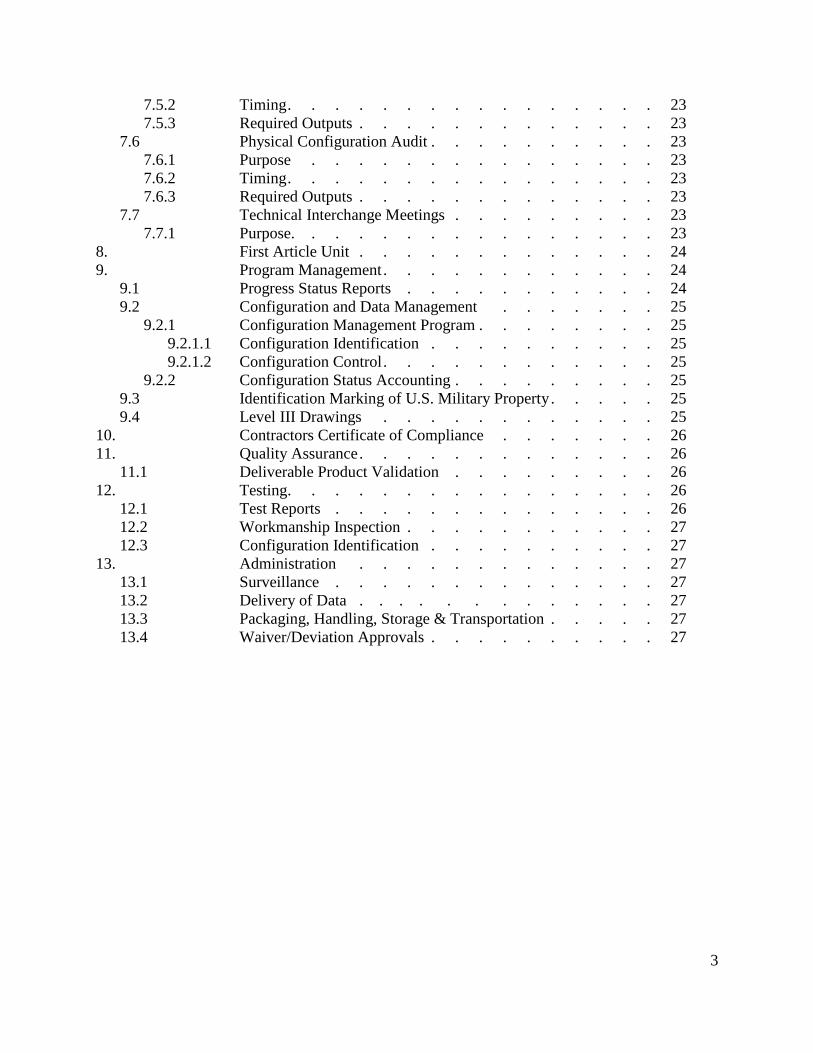
7.5.2 Timing . . . . . . . . . . . . . . . . 23
7.5.3 Required Outputs . . . . . . . . . . . . . 23
7.6 Physical Configuration Audit . . . . . . . . . . 23
7.6.1 Purpose . . . . . . . . . . . . . . . 23
7.6.2 Timing . . . . . . . . . . . . . . . . 23
7.6.3 Required Outputs . . . . . . . . . . . . . 23
7.7 Technical Interchange Meetings . . . . . . . . . 23
7.7.1 Purpose. . . . . . . . . . . . . . . . 23
8. First Article Unit . . . . . . . . . . . . . 24
9. Program Management . . . . . . . . . . . . 24
9.1 Progress Status Reports . . . . . . . . . . . 24
9.2 Configuration and Data Management . . . . . . . 25
9.2.1 Configuration Management Program . . . . . . . . 25
9.2.1.1 Configuration Identification . . . . . . . . . . 25
9.2.1.2 Configuration Control . . . . . . . . . . . . 25
9.2.2 Configuration Status Accounting . . . . . . . . . 25
9.3 Identification Marking of U.S. Military Property . . . . . 25
9.4 Level III Drawings . . . . . . . . . . . . 25
10. Contractors Certificate of Compliance . . . . . . . 26
11. Quality Assurance . . . . . . . . . . . . . 26
11.1 Deliverable Product Validation . . . . . . . . . 26
12. Testing. . . . . . . . . . . . . . . . 26
12.1 Test Reports . . . . . . . . . . . . . . 26
12.2 Workmanship Inspection . . . . . . . . . . . 27
12.3 Configuration Identification . . . . . . . . . . 27
13. Administration . . . . . . . . . . . . . 27
13.1 Surveillance . . . . . . . . . . . . . . 27
13.2 Delivery of Data . . . . . . . . . . . . . 27
13.3 Packaging, Handling, Storage & Transportation . . . . . 27
13.4 Waiver/Deviation Approvals . . . . . . . . . . 27
4
AN/FPN-63(V) Precision Approach Radar (PAR) Replacement
Statement of Work (SOW)
1. SCOPE
This SOW establishes and defines requirements relating to the AN/FPN-63(V) PAR Life Cycle
Extension (LCE). The entity performing the work as described in this SOW shall hereafter be
referred to as the contractor.
2. BACKGROUND
Space and Naval Warfare Systems Command (SPAWAR) Systems Center Pacific (SSC Pacific)
is the In-Service Engineering Agent (ISEA) for the AN/FPN-63(V) PAR system. The Air Traffic
Control (ATC) Systems Division, Approach Systems Branch of the Naval Air Warfare Center
Aircraft Division (NAWC-AD) Patuxent River (Code 4.5.8), has been tasked by NAVAIR PMA
213 (Naval Air Traffic Management Systems, Program Office) to support the AN/FPN-63(V)
Life Cycle Extension Program.
2.1. HISTORY
To meet the Naval Aviation mission, the Navy procured a field change upgrade, solid state
AN/FPN-63(V), in 1978. The AN/FPN-63(V) PAR is installed and used at Navy and Marine
Corps air installations to provide safe, orderly, and expeditious recovery of aircraft in
Instrument Meteorological Condition (IMC). There are 35 field units in use today within and
out of the Continental United States (CONUS).
The AN/FPN-63(V) provides talk-down capabilities to land military and civil aircraft during
reduced meteorological conditions. It also provides in-garrison training for controllers and
pilots in support of aircraft carrier talk-down final approach landings.
The AN/FPN-63(V) is also used in conjunction with an airport surveillance radar system to
provide a complete Ground Control Approach (GCA) capability for Navy, Marine Corps, and
other military and civilian aircraft as required. Azimuth (AZ), Elevation (EL), and Range
(RNG) to touchdown information are provided and displayed on the operator’s console. This
positional information of glideslope and center line deviation is then used by the air traffic
controller to direct the aircraft commander, by radio communication, to a precision
instrument landing. In addition, the radar set turntable allows for rapid realignment to
touchdown points on multiple runways when prevailing weather conditions change.
The current fielded AN/FPN-63(V) has approached the end of its economic and
technological life. Several components in this radar system have been in service more than
15 years past their estimated product life cycle. Obsolescence issues have been targeted for
remedy through a series of engineering changes. The original equipment manufacturer
(OEM) predicts technical system engineering support will be hard to find within 3-6 years,
and after that the system will become completely unsupportable. Since other vendors have no

5
interest in continuing to support this obsolete technology, the system must undergo a life
cycle extension to meet the Navy’s needs and to serve as an interim bridge until Joint
Precision Approach Landing Systems (JPALS) full operation capability (FOC) is reached in
2024. Otherwise, the supportability of this system will continue to deteriorate and ultimately
mission effectiveness will be lost.
2.2. EXISTING SYSTEM CONFIGURATION
The AN/FPN-63(V) radar set consists of the PAR shelter, operations equipment, interface
cabling, and radar turntable.
• The PAR shelter houses the antennas, transmitters, receivers, digital moving target indicator
(DMTI) processor, PAR indicator, radar remoting equipment and ancillary equipment
groups. Independent transmitters and receivers provide one operational channel and one “hot
standby” channel. This allows the operator to use one set of equipment, while a technician
performs maintenance on the other set.
• Operations equipment, operating remotely in conjunction with the PAR shelter, consists of
remoting equipment, maintenance and supervisor’s control panels, and up to six AZ-EL
range indicators for use by the air traffic controllers. The solid-state AZ-EL range indicator
generates its own internal map, sweeps, range marks, and cursors. A single cursor adjustment
allows alignment of each cursor with the runway centerline.
• Interface cabling consists of AN/FAC-6(V)1 Fiber Optics Intersite System (FOIS).
• Radar turntable, operating locally and remotely for runway setup, is capable to cover 6 – 12
runway ends with rotation speed of 0.5 rpm in less than 5 minutes.
3. APPLICABLE DOCUMENTS AND ORDER OF PRECEDENCE
The following is a list of known documents that will be needed, used and referred to during the
performance of the technical and engineering services required by this SOW. Unless otherwise
specified, the revision level and date of each document specification or standard cited, or referred
to within this SOW shall be the most current of superseding versions.
3.1. PRECEDENCE OF DOCUMENTS
In the event a conflict arises between the text of this contract and the references or drawings
sited herein, the text of this contract shall take precedence. Nothing in this contract,
however, shall supersede applicable laws and regulations unless a specific exemption has
been obtained.
Specifications:
MIL-DTL-5541F Chemical Conversion Coatings on Aluminum and
Aluminum Alloys
MIL-STD-13231 Marking of Electronic Items
MIL-S-901 D Shock Tests, High Impact (H.I) Shipboard Machinery,
Equipment, and Systems, Requirements For

6
MIL-PRF-31032B Printing Wiring Boards, General Specification for
MIL-STD-129P Military Marking for Shipment and Storage
MIL-STD-130 N Identification of Marking of U.S. Military Property
MIL-STD-461F Requirements for the Control of Electromagnetic
Interference Characteristics of Equipment
MIL-STD-810 G Test Method Standard for Environmental Engineering
Considerations and Laboratory Tests
MIL-STD-961E(1) Defense and Program-Unique Specifications Format and
Content
Handbooks:
MIL-HDBK-217 F (2) Reliability Prediction of Electronic Equipment
MIL-HDBK-454B General Guidelines for Electronic Equipment
MIL-HDBK-2036 Electronic Equipment Specifications; preparation of
MIL-HDBK-61A Configuration Management Guidance
MIL-HDBK-3001(NOT1) Guide to the General Style and Format of U.S. Navy Work
Package Technical Manuals
Reference Documents:
DFARS 252.211-7007 Reporting of Government Furnished Property Equipment in
the DoD Item Unique Identification (IUID) Registry
ANSI/J-STD-001 Requirements for Soldered Electrical and Electronic
Assemblies
IPC-A-610 Acceptability of Electronic Assemblies
UFC 4-133-01N Unified Facilities Criteria (UFC), Design: Navy Air Traffic
Control Facilities
ISO 9001:2000 AS9100 Quality Management
ICAO Annex 10 Volume I: Aeronautical Telecommunications
NAVAIR 16-1-520 US Standard Flight Inspection Manual
National Telecommunications and Information
Administration (NTIA) Manual of Regulation and
Procedures for Federal Radio Frequency Management.
NAVAIRINST 13800.17 Procedures and Responsibilities for Certification and
Verification of the Precision Approach and Landing
System
NAVAIRINST 4355.19D Systems Engineering Technical Review Process
NAVAIRINST 00-25-300 Technical Manual Specification

7
UDI-M-22402 Publications Package, Field Change
DoDD 8500.1 Information Assurance
DoDI 8500.2 Information Assurance Implementation
DoDI 8510.bb DoD Information Assurance Certification and
Accreditation Process (DIACAP)
DoDI 8510.1 DoD Information Technology Security Certification and
Accreditation Process (DITSCAP)
NAWCAD 43140-00991 General Acceptance Test Plan
Technical Manuals:
EE216-LA-OMI-010 - Volume 1, Chapters 1-8; Operation and Maintenance
Instructions
EE216-LA-OMI-020 - Volume 2, Part 1; Operation and Maintenance
Instructions
EE216-LA-OMI-030 - Volume 2, Part 2; Operation and Maintenance
Instructions
EE216-LA-MMD-010 - Volume 1, Chapters 1-8, Appendix A; Depot and Overhaul
Maintenance Instructions
EE216-LA-MMD-020 - Volume 2, Chapters 9-11; Depot and Overhaul Maintenance
Instructions
4. GENERAL REQUIREMENTS
Four years of AN/FPN-63(V) trend data identified the following six (6) top system degraders,
listed below in order of priority.
1. Receiver Group
2. Transmitter Group
3. Multiplexer-Demultiplexer Group
4. Control Console (Indicator)
5. Signal Data Converter (Processor)
6. Group and Azimuth & Elevation Antenna Group.
It is the intent of the Government to procure a Non-Developmental Item (NDI) LCE modifica-
tion to upgrade and/or replace as the threshold the top five (5) system performance degraders
with the objective to upgrade and/or replace all six(6) system performance degraders.

8
The PAR LCE shall be compatible with the design criteria established for U.S. Navy and Marine
Corps ATC facilities so as not to degrade air traffic controllers’ ability to provide safe, orderly
and expeditious air traffic services. The PAR LCE will enable aircraft to routinely execute safe
precision approaches to land at fixed base air-fields during periods of low ceiling and reduced
visibility, or when pilots are unable to identify a landing approach path. The fixed base mission
determines the base infrastructure and the PAR LCE must support that mission recognizing
factors such as: weather, terrain, aircraft mix, operational tempo, and electronic environment.
The PAR LCE shall provide for Ground Controlled Approach (GCA) to 100 feet and 0.25 NM.
The PAR LCE shall comply with the unrestricted facility classification commissioning flight
inspection tolerances for precision approaches as defined in the U.S. Standard Flight Inspection
Manual (NAVAIR 16-1-520).
The PAR LCE shall provide transparent coexistence with existing standardized position cabine-
try in the radar air traffic control facility and shall utilize existing AN/FPN-63(V) cabinetry and
foundations within the AN/FPN-63(V) shelter and Radar Air Traffic Control Facility when feas-
ible. All upgraded assemblies shall be compatible and/or interface with all non-modified/retained
components, sub-assemblies and existing system/foundation infrastructure.
The Government will provide an AN/FPN-63(V) shelter, and operations equipment as
Government Furnished Property (GFP) to be delivered to the contractor within 30 days after
award. All GFP equipment shall be returned to the SPAWAR Pacific upon completion of this
contract.
The contractor shall minimize the cost of Non-Recurring Engineering.
All items produced under this contract shall be governed by the requirements of the
specifications in this SOW. No changes shall be made to these documents without prior written
approval by the Procuring Contracting Officer (PCO) and the Technical Point of Contact
(TPOC).
5. OPERATIONAL REQUIREMENTS
The PAR LCE must be highly reliable, readily maintainable, and interoperable with existing air
traffic control systems. The PAR LCE must use a common O&D maintenance philosophy and
utilize to the greatest extent possible parts and components in the navy supply system. The
amount of support equipment and required maintenance personnel should be considered to
minimize operation and support costs. The PAR LCE shall meet or exceed the minimum
requirements identified in this section.
5.1. ENVIRONMENTAL REQUIREMENTS
Other than specified, the PAR LCE shall meet the environmental requirements as specified in
MIL-STD-810G.

9
5.1.1. TEMPERATURE
Operating Temperature: 0⁰ F to +122⁰ F
Non-Operating Temperature: -80⁰ F to +160⁰ F
5.1.2. HUMIDITY
Operating and Non-Operating Relative Humidity: 0 to 95% non-condensing
5.1.3. ALTITUDE
Operating and Non-Operating Altitude: at -100 feet to 10,000 feet sea level
5.1.4. WINDS
Wind Speed for Operating: 65 knots
Wind Speed for Non-Operating: 100 knots
5.1.5. ELECTROMAGNETIC INTERFERENCE (EMI)/ELECTROMAGNETIC
COMPATIBILITY (EMC) REQUIREMENTS
The PAR LCE shall be designed to meet the EMI/EMC requirements as specified in
MIL-STD-461F.
5.2. PAR OPERATIONAL AVAILABILITY (Ao)
The PAR must operate in all climatic conditions, terrain, and geographic locations in which
Navy and Marine Corps Air Stations are located. Furthermore, it must be able to operate
during times of limited visibility, including rain, snow, smoke, fog, and darkness. The PAR
shall be operable in conditions with high humidity, sand, smoke, dust, fog, or in temperate,
polar, alpine, swampland, desert, and maritime regions of the earth. The PAR Ao shall be
99%.
5.3. PAR MAINTENANCE
5.3.1. TOOLS AND TEST EQUIPMENT
Common tools and general purpose electronic test equipment (GPETE) shall be used to
the maximum extent possible. No special tools or special purpose electronic test
equipment (SPETE) shall be required.
5.3.2. PERIODIC INSPECTION AND PREVENTIVE MAINTENANCE

10
Periodic inspection requirements and preventive maintenance inspections shall be
sufficient to ensure system components are operational and/or prepare for IMC.
Maintenance shall be simplified to allow technicians to service and sustain the PAR
without having to rely on In-Service Engineering Activity (ISEA)/depot support.
Preventive maintenance shall be performed at the organizational level. Mean time to
perform preventive maintenance shall be no more than one hour per week (Threshold),
and should be no more than 30 minutes per week (Objective). The preventive
maintenance downtime shall not exceed 30 minutes for any single maintenance event.
The contractor shall provide data to perform the Reliability Centered Maintenance
(RCM) analysis and shall provide data for inclusion in generating Maintenance Index
Pages (MIPs) and Maintenance Requirement Cards (MRCs). (Contract Data Requirement
List (CDRL A001, A002)
5.3.3. MEAN TIME BETWEEN FAILURE (MTBF): Mean Time Between Failure
is used to measure the system reliability. It is calculated by dividing the total system
operating time by the number of failures requiring corrective maintenance actions. The
PAR LCE threshold for MTBF shall be greater than 2000 hours with an objective of
greater than 3000 hours.
5.3.4. MEAN TIME BETWEEN CRITICAL FAILURE (MTBCF): A critical failure
is defined as any failure that deems the system non-operational or does not allow the
system to perform its intended mission. The PAR LCE threshold for MTBCF shall be
greater than 4000 hours with an objective of greater than 6000 hours.
5.3.5. MEAN TIME TO REPAIR (MTTR): MTTR is calculated by measuring all
potential maintenance actions from the time a failure is identified until the system is
brought back to a full operational status. As an example, this would include the time to
power down the system, troubleshooting time, removal and replacement of the failed
item, system power-up and verification of system repair actions. The PAR LCE MTTR
for all repair actions shall have a threshold of less than 1 hour with an objective of less
than 30 minutes.
5.3.6. MANPOWER AND PERSONNEL
Operation and maintenance of the PAR LCE should reduce and shall not increase current
Navy or Marine Corps manpower authorization or skill level requirements.
5.3.7. TRAINING CONCEPT
Air traffic controller and maintenance technician training shall readily merge with
existing ATC training pipelines currently conducted at existing Navy/Marine Corps ATC
Schools in conjunction with the below statements, and shall reduce or maintain the
overall training times required.

11
Dynamic Training Simulator: Controller training shall be provided that includes
parameters that affect actual operation such as aircraft characteristics and environmental
conditions. The training simulator shall exactly duplicate the displays and controls of the
operational PAR LCE, and shall provide heading, turn rate, altitude, and rate of climb and
descent, and ground speed controls. The trainee’s simulated aircraft shall be able to be
controlled by a trainer via a separate display. The training simulator shall be capable of
recording the training session for playback.
Authoring Instructional Materials System (AIMS) Training: The contractor shall
work with Naval Air Technical Training Center (NATTC) Pensacola to develop a
training change package for incorporation into existing course curriculum and provide
input for fleet “difference” training. The contractor shall update Schoolhouse Schematics
and provide updated change information to the Government. The contractor shall provide
the above training change package in AIMS format to the Government. (CDRL A003)
Trainer Training: The contractor shall host one training event capable of supporting
eight people at the contractor facility no more than 180 days after acceptance of the first
article unit. (CDRL A004)
5.3.8. PROVISIONING AND LOGISTIC SUPPORT
The contractor shall develop and deliver the documents indicated in the below sub-
paragraphs to the Government. These documents shall go through a Government review
cycle. All documents must be completed and the final version delivered to the
Government prior to the delivery of the First Article Test Unit.
The contractor shall provide provisioning parts data containing the data elements required
for the Interactive Computer Aided Provisioning System (ICAPS) data file exchange
format. This parts data is acceptable in MS Excel format providing the required ICAPS
data elements are identified by column header. The contractor shall provide all Supple-
mentary Provisioning Technical Data (SPTD) to include data sheets and drawings re-
quired to support the parts data. To the maximum extent possible PAR LCE components
shall be readily available through current stocks within the DoD supply system at the
Lowest Repairable Unit (LRU). The product baseline shall be frozen prior to submission
of this data. (CDRL A005)
5.3.8.1 Integration Package
The contractor shall prepare Integration Procedures in the contractor format, which
shall present in detail all parts that need to be removed from the AN/FPN-63(V)
system, explain in detail all modifications required, provide a list of new parts to be
installed, detailed integration instructions, an integration drawing package, a list of
materials and tools required, typical time to complete, and check out procedures to
ensure the complete system functionality. (CDRL A006)
The contractor shall be present at the designated Government site 30 days or earlier,
after the delivery of the first and second production units to support
validation/verification testing of integration procedures.

12
5.3.8.2 Technical Manual Update Pages
The following technical manuals will be provided in PDF format as GFI for the
proposal and in word perfect format upon award of the contract. The contractor shall
review the following technical manuals and provide comprehensive updates to
support the Organizational to Depot (O to D) level maintenance of the AN/FPN-
63(V) LCE configuration. Contractor shall coordinate with the Government to obtain
new Technical Manual numbers.
EE216-LA-OMI-010 - Volume 1, Chapters 1-8; Operation and Maintenance
Instructions
EE216-LA-OMI-020 - Volume 2, Part 1; Operation and Maintenance
Instructions
EE216-LA-OMI-030 - Volume 2, Part 2; Operation and Maintenance
Instructions
EE216-LA-MMD-010 - Volume 1, Chapters 1-8, Appendix A; Depot and Overhaul
Maintenance Instructions
EE216-LA-MMD-020 - Volume 2, Chapters 9-11; Depot and Overhaul Mainten-
ance Instructions
The contractor shall either update or create a new Technical Manual for
comprehensive troubleshooting that supports repair of displays. (CDRL A007)
5.3.8.3 Spares
The contractor shall provide a Supply Support Summary and Data Products which
will be used to identify Installation/Check-Out (INCO) and interim requirements, and
catalog the range and quantity of spares, repair parts and support items to be acquired
to operate, maintain, and provide for the life cycle support of the PAR LCE
configuration. (CDRL A008)
Additionally, the contractor shall provide a spares parts kit to support INCO and inte-
rim spares for the PAR LCE configuration that were identified in CDRL A008.
Spares shall be at LRU level based on an engineering failure rates and expected likely
hood of LRU’s failing during the PAR LCE integration event.
5.3.8.4 Diminishing Manufacturing Sources of Material Supply (DMSMS)
/Parts Obsolescence
The Contractor shall resolve all parts obsolescence and/or diminishing manufacturing
issues that arise with respect to the hardware to be delivered. These costs may not be
charged to any other line items or contracts. The Supply Support Summary shall in-
clude a DMSMS report to address obsolescence concerns. (CDRL A009)
5.3.8.5 Nomenclature Assignment
The contractor shall provide the data necessary for nomenclature assignment,
revision, or cancellation. Contractor shall provide draft nomenclature DD61 form.
(CDRL A010)

13
5.3.8.6 Unique Item Identification
A Unique Item Identification Device shall be attached to each replaceable item and
the system in accordance with MIL-STD-130N and the clause at DFARS 252.211-
7003, “Item Identification and Valuation (JUN 2011)”. Marked items shall be
registered and validated with the DOD UID Registry. All production assets requiring
radio frequency identification (RFID) shall comply with the requirements of MIL-
STD-129P.
5.4. DOCUMENTATION AND CONFIGURATION CONTROL
The developing contractor shall provide all required documents to support operation,
maintenance, and hardware/software configuration control in Microsoft Office 2003 format
or later.
5.5. SAFETY
The PAR LCE shall not be comprised of toxic chemicals, hazardous materials, or ozone-
depleting substances, and shall not be produced using manufacturing processes that have a
detrimental impact upon the environment, from the time of design and manufacture through
its life-cycle.
The PAR operational user interface shall support system operations to allow operators to
perform their duties minimizing the labor hours required to maintain the system.
5.6. LOCATION OF PAR INSTALLATION
The PAR LCE will be installed by the Government at existing locations utilizing existing
AN/FPN-63(V) cabinetry and foundations within the PAR shelter and radar Air Traffic
Control Facility in accordance with contractor provided instructions.
5.7. SYSTEM ALIGNMENT
To verify system accuracy after preventive and corrective maintenance or prior to flight
operations, the PAR LCE shall be capable of aligning the antennas to the designated target
(i.e. corner reflector) location and display the alignment data on the display consoles in terms
of angle and range.
5.8. PAR INPUT POWER REQUIREMENTS
The PAR shall be compatible and operate with both of the following power sources: primary
commercial electrical power or backup power.
5.8.1. PRIMARY COMMERCIAL ELECTRICAL POWER
120/208 VAC, 60 Hz, 4 wire, three phase, 12.8 KVA
14
5.8.2. UNINTERRUPTIBLE POWER SUPPLY (UPS)
The PAR shall be compatible with an UPS which shall provide in-line filtering of
commercial power and provide instant protection from a momentary power
interruption. The UPS shall have the capacity to power the PAR LCE display and
processor to allow for orderly shutdown. Within the proposal, the contractor shall
provide detailed information regarding UPS specification, size and location within
PAR shelter.
5.9. PAR REMOTE OPERATION
The remote operation capability of the PAR LCE from the radar site to the radar air traffic
control facility shall be up to 10,000 feet (Threshold), with an objective of 16,000 feet
(Objective). In addition to PAR displays in the radar air traffic control facility, the PAR LCE
system functions shall be able to be controlled remotely from the radar air traffic control
facility.
5.10. PAR DISPLAY CAPABILITY
The PAR LCE shall use a digital full-color display with multi-function capabilities for
maintenance, operations, and training. The PAR LCE display shall be suitable for use in
both a daylight and limited light environment. Common user interfaces to the digital
display shall be used in the PAR LCE, to include display of raw data/ground target, as
well as aircraft target and track data blocks.
The PAR LCE shall incorporate variable target trail history and digital weather display
for severe thunderstorm cell avoidance.
The PAR LCE shall incorporate Azimuth-high (Azimuth tilt) and Elevation-wide
(Elevation twist) indicators. The PAR LCE shall incorporate crosshair vertical and lateral
displays of course deviation from centerline and glideslope.
5.11. PAR ACQUISITION AND TRACKING
The PAR LCE shall be able to detect and display all targets within the prescribed
scan/coverage areas (refer to paragraph 5.13) to include: course line for azimuth,
glideslope and lower safe limits for elevation, and range.
The PAR LCE shall provide tracking capability so controllers can acquire or track the
targets on both master and slave control consoles. The tracked target shall have a tracking
symbol or indication to indicate the target being tracked and tracked information shall be
displayed in range and altitude on both AZ and EL display.
15
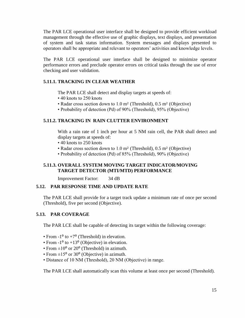
The PAR LCE operational user interface shall be designed to provide efficient workload
management through the effective use of graphic displays, text displays, and presentation
of system and task status information. System messages and displays presented to
operators shall be appropriate and relevant to operators’ activities and knowledge levels.
The PAR LCE operational user interface shall be designed to minimize operator
performance errors and preclude operator errors on critical tasks through the use of error
checking and user validation.
5.11.1. TRACKING IN CLEAR WEATHER
The PAR LCE shall detect and display targets at speeds of:
• 40 knots to 250 knots
• Radar cross section down to 1.0 m² (Threshold), 0.5 m² (Objective)
• Probability of detection (Pd) of 90% (Threshold), 95% (Objective)
5.11.2. TRACKING IN RAIN CLUTTER ENVIRONMENT
With a rain rate of 1 inch per hour at 5 NM rain cell, the PAR shall detect and
display targets at speeds of:
• 40 knots to 250 knots
• Radar cross section down to 1.0 m² (Threshold), 0.5 m² (Objective)
• Probability of detection (Pd) of 85% (Threshold), 90% (Objective)
5.11.3. OVERALL SYSTEM MOVING TARGET INDICATOR/MOVING
TARGET DETECTOR (MTI/MTD) PERFORMANCE
Improvement Factor: 34 dB
5.12. PAR RESPONSE TIME AND UPDATE RATE
The PAR LCE shall provide for a target track update a minimum rate of once per second
(Threshold), five per second (Objective).
5.13. PAR COVERAGE
The PAR LCE shall be capable of detecting its target within the following coverage:
• From -1⁰ to +7⁰ (Threshold) in elevation.
• From -1⁰ to +13⁰ (Objective) in elevation.
• From ±10⁰ or 20⁰ (Threshold) in azimuth.
• From ±15⁰ or 30⁰ (Objective) in azimuth.
• Distance of 10 NM (Threshold), 20 NM (Objective) in range.
The PAR LCE shall automatically scan this volume at least once per second (Threshold).

16
5.14. PAR ANTENNA CONTROL
• The PAR LCE shall be capable to vertically tilt the azimuth antenna from -1⁰ to +7⁰
(Threshold), from -1⁰ to +13⁰ (Objective).
• The PAR LCE shall be capable to horizontally twist the elevation antenna ±10⁰ or 20⁰
(Threshold), from ±15⁰ or 30⁰ (Objective).
5.15. PAR RANGE ACCURACY
The PAR LCE shall provide range accuracy for all targets within the prescribed scan
coverage: for search and track, ±2% of the actual range from touchdown or ±60 feet,
whichever is greater (Threshold), ±1% for track only (Objective) at two sigma.
5.16. PAR ELEVATION ANGULAR ACCURACY
• For search and track, ± 0.23⁰ (Threshold), for track only ±0.12⁰ (Objective) at two
sigma.
• For elevation twist angular accuracy, ±0.25⁰.
5.17. PAR AZIMUTH ANGULAR ACCURACY
• For search and track, ± 0.34⁰ (Threshold), for track only ±0.18⁰ (Objective) at two
sigma.
• For azimuth tilt angular accuracy, ±0.25⁰.
5.18. PAR TARGET SEPERATION/RESOLUTION
• The PAR LCE shall be capable of separating two 1.0 m² targets at the same azimuth by
400 feet (Threshold), 200 feet (Objective) in range at two sigma.
• The PAR LCE shall be capable of separating two 1.0 m² targets at the same range by
1.2⁰ in azimuth at two sigma.
• The PAR LCE shall be capable of separating two 1.0 m² targets at the same range and
azimuth by 0.6⁰ in elevation at two sigma.
5.19. RUNWAY COVERAGE
The PAR LCE shall be capable of providing precision approaches to a minimum of six
runways, dependent on airfield layout/runway configuration (runway lengths and distance
between runways and taxiways).
17
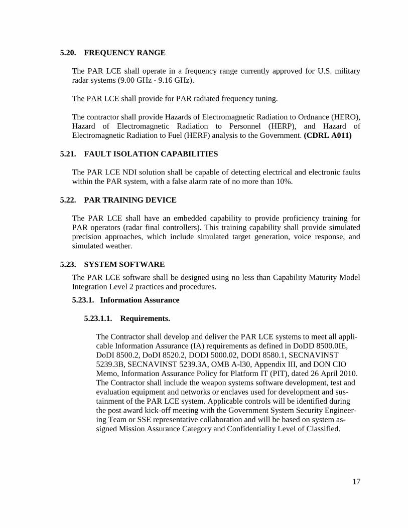
5.20. FREQUENCY RANGE
The PAR LCE shall operate in a frequency range currently approved for U.S. military
radar systems (9.00 GHz - 9.16 GHz).
The PAR LCE shall provide for PAR radiated frequency tuning.
The contractor shall provide Hazards of Electromagnetic Radiation to Ordnance (HERO),
Hazard of Electromagnetic Radiation to Personnel (HERP), and Hazard of
Electromagnetic Radiation to Fuel (HERF) analysis to the Government. (CDRL A011)
5.21. FAULT ISOLATION CAPABILITIES
The PAR LCE NDI solution shall be capable of detecting electrical and electronic faults
within the PAR system, with a false alarm rate of no more than 10%.
5.22. PAR TRAINING DEVICE
The PAR LCE shall have an embedded capability to provide proficiency training for
PAR operators (radar final controllers). This training capability shall provide simulated
precision approaches, which include simulated target generation, voice response, and
simulated weather.
5.23. SYSTEM SOFTWARE
The PAR LCE software shall be designed using no less than Capability Maturity Model
Integration Level 2 practices and procedures.
5.23.1. Information Assurance
5.23.1.1. Requirements.
The Contractor shall develop and deliver the PAR LCE systems to meet all appli-
cable Information Assurance (IA) requirements as defined in DoDD 8500.0IE,
DoDI 8500.2, DoDI 8520.2, DODI 5000.02, DODI 8580.1, SECNAVINST
5239.3B, SECNAVINST 5239.3A, OMB A-l30, Appendix III, and DON CIO
Memo, Information Assurance Policy for Platform IT (PIT), dated 26 April 2010.
The Contractor shall include the weapon systems software development, test and
evaluation equipment and networks or enclaves used for development and sus-
tainment of the PAR LCE system. Applicable controls will be identified during
the post award kick-off meeting with the Government System Security Engineer-
ing Team or SSE representative collaboration and will be based on system as-
signed Mission Assurance Category and Confidentiality Level of Classified.
18
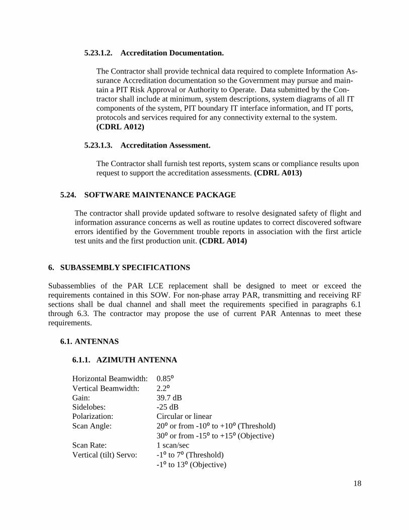
5.23.1.2. Accreditation Documentation.
The Contractor shall provide technical data required to complete Information As-
surance Accreditation documentation so the Government may pursue and main-
tain a PIT Risk Approval or Authority to Operate. Data submitted by the Con-
tractor shall include at minimum, system descriptions, system diagrams of all IT
components of the system, PIT boundary IT interface information, and IT ports,
protocols and services required for any connectivity external to the system.
(CDRL A012)
5.23.1.3. Accreditation Assessment.
The Contractor shall furnish test reports, system scans or compliance results upon
request to support the accreditation assessments. (CDRL A013)
5.24. SOFTWARE MAINTENANCE PACKAGE
The contractor shall provide updated software to resolve designated safety of flight and
information assurance concerns as well as routine updates to correct discovered software
errors identified by the Government trouble reports in association with the first article
test units and the first production unit. (CDRL A014)
6. SUBASSEMBLY SPECIFICATIONS
Subassemblies of the PAR LCE replacement shall be designed to meet or exceed the
requirements contained in this SOW. For non-phase array PAR, transmitting and receiving RF
sections shall be dual channel and shall meet the requirements specified in paragraphs 6.1
through 6.3. The contractor may propose the use of current PAR Antennas to meet these
requirements.
6.1. ANTENNAS
6.1.1. AZIMUTH ANTENNA
Horizontal Beamwidth: 0.85⁰
Vertical Beamwidth: 2.2⁰
Gain: 39.7 dB
Sidelobes: -25 dB
Polarization: Circular or linear
Scan Angle: 20⁰ or from -10⁰ to +10⁰ (Threshold)
30⁰ or from -15⁰ to +15⁰ (Objective)
Scan Rate: 1 scan/sec
Vertical (tilt) Servo: -1⁰ to 7⁰ (Threshold)
-1⁰ to 13⁰ (Objective)

19
6.1.2. ELEVATION ANTENNA
Horizontal Beamwidth: 3.8⁰ csc²
Vertical Beamwidth: 0.55⁰
Gain: 40.3 dB
Sidelobes: -25 dB
Polarization: Circular or linear
Scan Angle: 8 ⁰, from -1⁰ to +7⁰ (Threshold)
14⁰, from -1⁰ to +13⁰ (Objective)
Scan Rate: 1 scan/sec
Horizontal (twist) Servo: 20⁰ or -10⁰ to +10⁰ (Threshold)
-15⁰ to +15⁰ (Objective).
6.2. TRANSMITTER
Frequency Range: 9.00 GHz – 9.16 GHz
Operating Frequency: 9.08 GHz
Frequency Tuning: Automatic Frequency Control (AFC) controlled by servo loop
Peak output Power: 80 KW minimum
Pulse Width: 0.2 usec nominal
PRF: 2750 Hz fixed
3300 Hz (7, 8, 9) staggered
6.3. RECEIVER
Type: Coherent
Frequency Range: 9.00 GHz – 9.16 GHz
Operating Frequency: 9.08 GHz
Minimum Discernable Signal: -101 dBm
Noise Figure: 11 dB
6.4. DISPLAY CONSOLE
Screen Monitor Size: Minimum 20 inch ruggedized flat screen, EMI shielded
Display Format: Elevation section in upper portion, Azimuth section in lower
section
Cursor Type: Logarithmic curves (Beta format) including glideslope, safety,
and courseline
Displayed Range: Selectable between 5 NM and 10 NM
Range Marks: Touchdown point dependent, 1 NM intervals, every 5 NM
range mark intensified
20
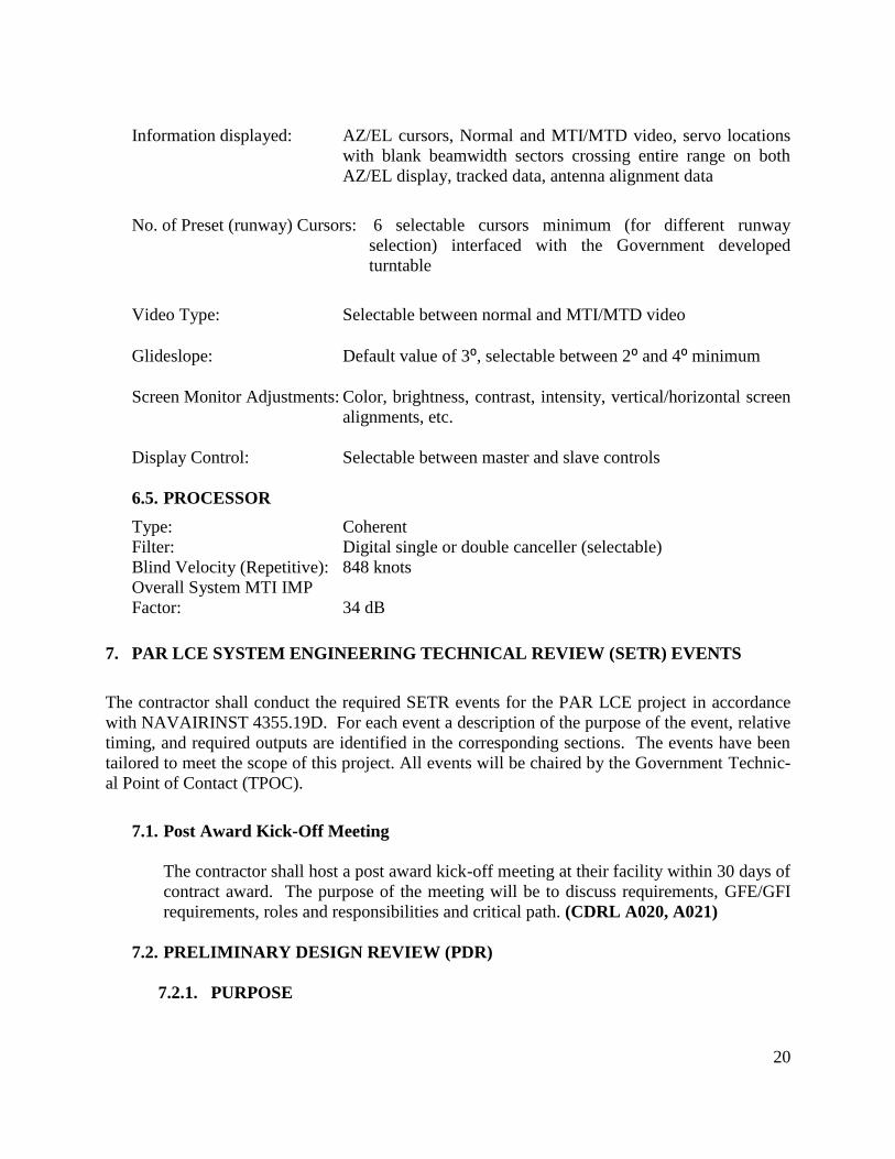
Information displayed: AZ/EL cursors, Normal and MTI/MTD video, servo locations
with blank beamwidth sectors crossing entire range on both
AZ/EL display, tracked data, antenna alignment data
No. of Preset (runway) Cursors: 6 selectable cursors minimum (for different runway
selection) interfaced with the Government developed
turntable
Video Type: Selectable between normal and MTI/MTD video
Glideslope: Default value of 3⁰, selectable between 2⁰ and 4⁰ minimum
Screen Monitor Adjustments: Color, brightness, contrast, intensity, vertical/horizontal screen
alignments, etc.
Display Control: Selectable between master and slave controls
6.5. PROCESSOR
Type: Coherent
Filter: Digital single or double canceller (selectable)
Blind Velocity (Repetitive): 848 knots
Overall System MTI IMP
Factor: 34 dB
7. PAR LCE SYSTEM ENGINEERING TECHNICAL REVIEW (SETR) EVENTS
The contractor shall conduct the required SETR events for the PAR LCE project in accordance
with NAVAIRINST 4355.19D. For each event a description of the purpose of the event, relative
timing, and required outputs are identified in the corresponding sections. The events have been
tailored to meet the scope of this project. All events will be chaired by the Government Technic-
al Point of Contact (TPOC).
7.1. Post Award Kick-Off Meeting
The contractor shall host a post award kick-off meeting at their facility within 30 days of
contract award. The purpose of the meeting will be to discuss requirements, GFE/GFI
requirements, roles and responsibilities and critical path. (CDRL A020, A021)
7.2. PRELIMINARY DESIGN REVIEW (PDR)
7.2.1. PURPOSE

21
The contractor shall conduct a PDR as a technical assessment establishing the complete
physically allocated baseline to ensure that the system under review has a reasonable
expectation of being judged operationally effective and suitable. This review represents a
physically architected system, preliminary detailed design by sub-system suppliers, and
critical technologies matured to Technology Readiness Level (TRL) 6. Completion of
PDR will establish the allocated baseline. The PDR shall be conducted at the contractor’s
facility. (CDRL A015, A020, A021)
7.2.2. TIMING
The contractor shall conduct this event approximately 120 days After Receipt of Order
(ARO) spell out. (CDRL A015)
7.2.3. REQUIRED OUTPUTS (CDRL A015)
1. Completed Sub-system specifications
2. Human Systems Design standards flowed to sub-systems
3. Reliability and Maintainability diagnostics have been addressed in design
allocations
4. Top Level Software Design Description and/or Software Architecture Description
complete
5. Requirements Verification Traceability Matrix (RVTM) covers sub-system
allocations
6. Draft Acceptance Test Plan
7. Draft First Article Test Plan
8. Complete Software Integration Plan
9. Sub-system R&M engineering analysis, Failure Modes, Effects, and Criticality
Analysis (FMECA) scheduled to support System Hazard Analysis
10. Logistics element requirements allocated to system design
11. Training requirements allocated to system design
12. IMS shows critical path through CDR
13. Program technical risks identified
14. Program execution risks identified
15. Draft Integration Procedure
7.3. CRITICAL DESIGN REVIEW (CDR)
7.3.1. PURPOSE
The contractor shall conduct a CDR as a technical assessment establishing the build
baseline to ensure that the system under review has a reasonable expectation of being
judged operationally effective and suitable. This review assesses the final design as
captured in product specifications for each Configuration Item in the system, and ensures
that item has been captured in detailed documentation. Product specifications for
hardware enable the fabrication, and include production drawings. Product specifications
for software enable coding of the Computer Software Configuration Item. The CDR
brings to closure technical risk mitigation and alternate design paths in detailed system
design. The CDR shall be conducted at the contractor’s facility. (CDRL A016, A020,
A021)

22
7.3.2. TIMING
The contractor shall conduct this event approximately 240 days ARO. (CDRL A016)
7.3.3. REQUIRED OUTPUTS (CDRL A016)
1. Completed system design specifications
2. Engineering drawings ready for release to manufacturing
3. Software Top Level Design Description and/or Software Architecture Description
updated
4. Software Interface Design Description or equivalent updated
5. Requirements Verification Traceability Matrix (RVTM) Complete
6. Test Plans are complete
7. System level R&M analyses complete-final allocations, math models, predictions,
FMECA, environmental, and diagnostics
8. Manufacturing and production planning complete
9. Logistics analysis complete and plans established
10. Training plan complete
11. IMS shows critical path through testing
12. Program technical risks identified and mitigation plans in place
13. Program execution risks identified and mitigation plans in place
14. Updated Integration Procedure
7.4. TEST READINESS REVIEW (TRR)
7.4.1. PURPOSE
The TRR is a technical assessment establishing the configuration used in test to ensure
that the system has a reasonable expectation of being judged operationally effective and
suitable. TRR will be conducted prior to First Article Test to ensure all requirements and
resources are in place to proceed. The TRR shall be conducted at the contractor’s
facility. (CDRL A017, A020, A021)
7.4.2. TIMING
TRR shall be conducted no less than 30 days prior to First Article Test. (CDRL A017)
7.4.3. REQUIRED OUTPUTS (CDRL A017)
1. Test report content mutually agreed upon
2. Data reduction procedures and responsibilities are documented and accepted
3. Data analysis procedures and responsibilities are documented and accepted
4. Logistics and supply support for testing is adequate
5. Detailed test schedule established and fully resourced
6. Technical risks are identified and mitigation plans in place
7. Execution risks are identified and mitigation plans in place
8. Government approved Factory Acceptance Test Procedure (ATP) in accordance
with the General Acceptance Test Plan (GATP)

23
7.5. PRODUCTION READINESS REVIEW (PRR)
7.5.1. PURPOSE
The contractor shall conduct a Production Readiness Review (PRR) as an examination of
a program to determine if the design is ready for production and the producer has
accomplished adequate production planning without incurring unacceptable risks that
will breach thresholds of schedule, performance, cost, or other established criteria. The
full, production-configured system is evaluated to determine that it correctly and
completely implements all system requirements, and whether the traceability of final
system requirements to the final production system is maintained. The PRR shall be
conducted at the contractor’s facility. (CDRL A018, A020, A021)
7.5.2. TIMING
Contractor shall conduct PRR 30 days after notification of the government’s intent to ex-
ecute procurement of the initial production kit. (CDRL A018)
7.5.3. REQUIRED OUTPUTS (CDRL A018)
1. Transition to manufacturing plan
2. All CDR action items have been closed or mitigated
3. Test report has been approved
4. Change control process has been established and the Government has approved
the production configuration baseline
5. Current risk assessment
6. Final Integration Procedure
7.6. PHYSICAL CONFIGURATION AUDIT (PCA)
7.6.1. PURPOSE
The Government will conduct a PCA to examine the actual configuration of the system
being produced in order to verify that the related design documentation matches the
system as specified in the contract. PCA shall be conducted at the contractor’s facility.
(CDRL A019)
7.6.2. TIMING
The Government will conduct a PCA prior to final acceptance (DD250) of the initial
production kits.
7.6.3. REQUIRED OUTPUTS
1. PCA report delivered and accepted
7.7. TECHNICAL INTERCHANGE MEETINGS (TIMs)
7.7.1. PURPOSE
24
TIMs shall be conducted on a monthly basis, at a minimum, in order to implement timely
resolution of technical risks. TIMs shall be conducted either via video teleconference,
teleconference or at a location designated by the Government. Locations shall be
designated at each TIM for the subsequent TIM. (CDRL A020, A021)
8. FIRST ARTICLE UNIT
The contractor shall prepare one first article unit for testing in accordance with the contract, to be
complete within 9 months or less after issue of first order and 30 days prior to the scheduled
acceptance testing. The contractor shall conduct a Factory acceptance test per Government
approved Factory Acceptance Test Procedure (ATP) at the contractor facility, in accordance with
the General Acceptance Test Plan (GATP). (CDRL A022)
Additionally, the PAR LCE must pass an FAA flight certification facilitated by the contractor
and witnessed by the Government. Upon successful completion of the Factory Acceptance Test
and the receipt of FAA Flight Certification, the contractor shall conduct a Government witnessed
Acceptance Test in accordance with a Government approved Acceptance Test Procedure at
contractor facility. Upon Government deemed successful completion of the Acceptance Test, the
Government will accept the First Article Unit which will then be provided as GFP to the
contractor to be used during production and returned to SPAWAR PAC upon completion of this
contract. The performance of the first article unit shall be functionally equivalent to the
performance of the deliverable production units per the SOW. The first article unit shall
maintain an equivalent mechanical form factor to the deliverable production units per the
mutually agreed upon Installation Drawing Package (IDP). (CDRL A006)
9. PROGRAM MANAGEMENT
The contractor shall appoint a knowledgeable individual who shall be the point of contact for all
work related to this contract.
9.1. PROGRESS STATUS REPORTS
The contractor shall submit a Progress Status Report and Project Schedules for review and
approval by the Government which contains, as a minimum, the following items for each
principal item to be supplied:
The project stages and milestones
Significant activities
Deliverables
Contractor manufacturing schedule
Assembly
Inspection
25
Tests
Trials
The Project Schedule shall provide sufficient detail to accurately track progress of the efforts;
the Project Schedule shall be updated regularly and supplied as part of the monthly Progress
Status Report. (CDRL A023)
9.2. CONFIGURATION AND DATA MANAGEMENT
9.2.1 Configuration Management Program
The contractor shall maintain a Configuration Management (CM) Program, which
includes an organizational structure with configuration control methods, configuration
audits, and configuration status accounting procedures. The CM program strategy shall
be documented via a CM plan in accordance with MIL-HDBK-61A and Electronic
Industries Alliance (EIA)-649. The program shall cover the duration of the contract.
(CDRL A024)
9.2.1.1 Configuration Identification
The configuration baseline will be established upon Government acceptance of a
Configuration Audit Summary Report (CASR). (CDRL A019)
9.2.1.2 Configuration Control
Configuration Baselines and documentation may be changed only as the result of an
Engineering Change Proposal (ECP) approved by the PMA213 Decentralized
Configuration Control Board (DCCB). (CDRL A025)
Variances from documented design/specification documents shall only be accepted
when a Request for Deviation (RFD) has been approved by the PMA213 DCCB.
(CDRL A026)
The contractor shall maintain records for all Class II ECPs and make them available
for Government review. Class II ECPs require Defense Contract Management
Agency (DCMA) or PMA213 classification concurrence. Engineering changes shall
be classified IAW MIL-HDBK-61A. To the maximum extent possible all hardware
and software changes shall be backward compatible with all existing hardware and
software configurations.
9.2.2 Configuration Status Accounting.
The contractor shall maintain procedures to track the status of changes to the baseline and
to units already produced and to track the implementation of approved changes.
9.3. IDENTIFICATION MARKING OF U.S. MILITARY PROPERTY
The contractor shall properly identify and mark U.S. Military property in accordance with
Defense Acquisition Regulation (DFARS) 252.211.7003.
26
9.4. LEVEL III DRAWINGS
Level III Engineering Drawings shall be prepared in accordance with MIL-STD-961E(C/1)
in CAD or CAD compatible format, or Solid works format. These drawings shall then be
made available to the Government 180 days or less after procurement of the drawings.
The contractor shall prepare product drawings and associated lists to provide the design,
engineering, manufacturing and quality assurance requirements information necessary to
enable the procurement or manufacture of an item essentially identical to the original item.
The products shall be defined to the extent necessary for a competent manufacturer to
produce an item identical to the original item. The products shall be defined to the extent
necessary for a competent manufacturer to produce an item, which duplicates the physical,
interface and functional characteristics of the original product, without additional design
engineering effort or recourse to the current design activity. Engineering data shall reflect
the approved, tested, and accepted configuration of the defined delivered item.
Drawings shall include Commercial and Government Entity (CAGE) Code, number and
revision assignments shall be coordinated through Government. Upon approval, all drawing
final signatures will be provided by the ISEA. (CDRL A027)
10. CONTRACTORS CERTIFICATE OF COMPLIANCE
The contractor shall provide a Certificate of Compliance (C of C) with each deliverable unit,
which certifies that all inspections and tests have been performed without fault in accordance
with paragraph 11 through 12.3, as well as copies of the Acceptance Test Reports. (CDRL
A028, A029)
All C of C’s, and Acceptance Test Reports, shall be signed by a representative of the appropriate
Quality Assurance Division of the contractor.
11. QUALITY ASSURANCE
The contractor shall have a documented Quality Management System based on an industry
standard such as ISO 9001:2000, AS9100 or equivalent standard which is subject to review and
approval by the Government.
11.1. DELIVERABLE PRODUCT VALIDATION
The Government shall have the right to perform scheduled visits to review the progress of the
program and quality of the hardware or perform site inspections of the product to review
performance against the specifications in the SOW. The Government representative will
give the contractor at least 48 hours advanced notification that a visit is going to be
conducted.
27
12. TESTING
The contractor shall conduct the testing identified in accordance with the General
Acceptance Test Plan NAWCAD document 43140-00991.
12.1. TEST REPORTS
The contractor shall generate and maintain test logs for all hardware to be delivered under
this contract. The contractor shall prepare inspection and test reports in accordance with the
contractor’s inspection and test methods. The contractor shall provide completed test data
sheets for inspection and test reports. (CDRL A029)
12.2. WORKMANSHIP INSPECTION
Each unit shall be inspected by the contractor to verify that it is free from workmanship
defects. Workmanship shall comply with industry-recognized standards listed in paragraph 3
of this SOW.
12.3. CONFIGURATION IDENTIFICATION
The contractor shall inspect each item to verify that its configuration is consistent with the
Governments accepted first article unit configuration.
13. ADMINISTRATION
13.1. SURVEILLANCE
The Government reserves the right to conduct necessary management and technical
surveillance and liaison within the contractor’s facilities as it pertains to this program.
13.2. DELIVERY OF DATA
The contractor shall supply data in accordance with the requirement and delivery schedule
given in the Contract Data Requirements List (CDRL). The contractor supplied data shall
comply with all requirements of this contract.
13.3. PACKAGING, HANDLING, STORAGE AND TRANSPORTATION
The contractor shall pack and ship the PAR LCE kits using best commercial practices and
ship by any approved traceable conventional mode of transportation. Handling of the PAR
LCE kits is not expected to pose any unusual problems. The contractor shall ensure the PAR
LCE kits are secured in a shipping case taking care that displays, buttons and switches are
protected. The PAR LCE kits should be shipped using best commercial practices for
shipping within the continental United States.
28
13.4. WAIVER/DEVIATION APPROVALS
The contractor shall request and obtain prior written approval for all waivers and deviations
relative to the requirements of this SOW from Contracts 2.5 and the TPOC. These requests
shall contain, as a minimum, a definition of the non-compliance, the net effect on applicable
specification(s) and corrective action to preclude recurrence. Approval of waivers must be
incorporated as a modification to the contract. (CDRL A026)