android things linux day 2017
TRANSCRIPT

Stefano Sanna(with Giovanni Di Gialluca)

Timeline
2008
2011
2014
2015
2016

Mr Sulu, our coordinates, please...
Physical World Cloud

At a glance
SAFETY & SECURITYSAFETY & SECURITY
HOME APPLIANCES
HOME APPLIANCES
CONNECTED CARS
CONNECTED CARSSMART METERSSMART METERS
INDUSTRY 4.0INDUSTRY 4.0
SALES & VENDINGSALES & VENDING
PORTABILITYPORTABILITY
LARGE, VIBRANT, PROFESSIONAL
COMMUNITY
LARGE, VIBRANT, PROFESSIONAL
COMMUNITY
FULL-STACK CLOUD
SERVICES
FULL-STACK CLOUD
SERVICESSECURITYSECURITY
ON DEVICE INTELLIGENCE
ON DEVICE INTELLIGENCE
MODERN ARCHITECTURE
AND LANGUAGES
MODERN ARCHITECTURE
AND LANGUAGES
Environment● Same architecture
● Same IDE (Android Studio)
● Same programming language(s)
● Same framework
● Same app (Activity) lifecycle
● Same UI widgets (UI?)
● Same application packaging
● Same reliable security for apps and frmware upgrade
● Same passionate community
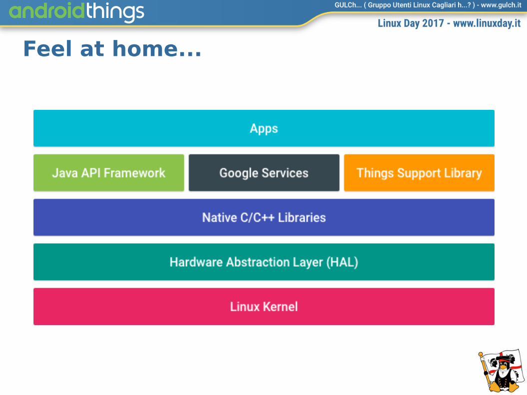
Feel at home...

… more or less! Where is the UI?
Where is the UI?

Android Things vs Android: in & out
CastDriveFirebase AnalyticsFirebase Cloud MessagingFirebase Realtime DatabaseFirebase Remote ConfigFirebase StorageFitInstance IDLocationNearbyPlacesMobile Vision
CastDriveFirebase AnalyticsFirebase Cloud MessagingFirebase Realtime DatabaseFirebase Remote ConfigFirebase StorageFitInstance IDLocationNearbyPlacesMobile Vision
CalendarContract
ContactsContract
DocumentsContract
DownloadManager
MediaStore
Settings
Telephony
UserDictionary
VoicemailContract
AdMob
Android Pay
Firebase App Indexing
Firebase Authentication
Firebase Dynamic Links
Firebase Invites
Firebase Notifications
Maps
Play Games
Search
Sign-In
CalendarContract
ContactsContract
DocumentsContract
DownloadManager
MediaStore
Settings
Telephony
UserDictionary
VoicemailContract
AdMob
Android Pay
Firebase App Indexing
Firebase Authentication
Firebase Dynamic Links
Firebase Invites
Firebase Notifications
Maps
Play Games
Search
Sign-In

SOM

SOM: System On ModuleA system on a module (SOM) is a board-level circuit that integrates a system function in a single module.
A typical SOM consists of:
● a microcontroller, microprocessor or digital signal processor (DSP)
● memory blocks including a selection of ROM, RAM, EEPROM and/or fash memory
● timing sources
● industry standards interface such as USB, FireWire, Ethernet, UART, SPI
● peripherals including counter-timers, real-time timers and power-on reset generators
● analog interfaces including ADCs and DACs
● voltage regulators and power management circuits
https://en.wikipedia.org/wiki/System_on_module

From prototype...
SYSTEM ON MODULE (SOM) WITH
OS AND APPS
SYSTEM ON MODULE (SOM) WITH
OS AND APPS
BASEBOARD FOR
PROTOTYPING
BASEBOARD FOR
PROTOTYPING

… to production
SYSTEM ON MODULE (SOM) WITH
OS AND APPS
SYSTEM ON MODULE (SOM) WITH
OS AND APPS
STACK OF DEDICATED
BOARDS
STACK OF DEDICATED
BOARDS
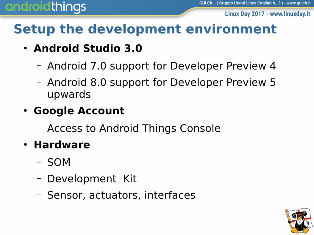
Setup the development environment● Android Studio 3.0
– Android 7.0 support for Developer Preview 4– Android 8.0 support for Developer Preview 5
upwards● Google Account
– Access to Android Things Console● Hardware
– SOM – Development Kit– Sensor, actuators, interfaces

Boards
Intel Edison Intel Joule NXP Pico i.MX6UL Raspberry Pi3
PRICE $55 > $200 $70 $22
SDK PRICE
$150 > $300 - $22
CPU Atom DC @500Mhz Atom QC @1.5GHz NXP i.MX6Ultralite ARM Cortex A7 @500MHz
Broadcom BCM2837QC @1.2GHz Cortex
A53
RAM 1GB 3-4GB 512MB 1GB
STORAGE
4GB 8-16GB 4GB microSD
DISPLAY
NO HDMI NO HDMI
CAMERA
NO CSI-2 NO CSI-2
AUDIO USB 2.0 USB 2.0 3.5mm Analog USB 2.0 & 3.5mm Analog
NET WiFi n, BT 4.0 WiFi ac, BT 4.2 Ethernet, WiFi n, BT 4.1 GB Ethernet, WiFi n, BT 4.1
USB USB 2.0 OTG 2x USB 2.0 HOST + USB 3.0 OTG
USB 2.0 HOST + USB 2.0 OTG
4x USB 2.0 HOST
GPIO 2x UART, 2x I2C,SPI 2ch, 14 GPIO
4x UART, 5x I2C, 2x SPI, up to 48 GPIO
8x UART, 4x I2C, 4x SPI, > 20 GPIO
2x UART, 2x I2C, 2x SPI, up to 26 GPIO

Select a board ● Intel Edison
– Damn small!– No UI, no Ethernet– ADB via USB– Obsolete (will not receive upgrades), but easily
sold on eBay at afordable price● Raspberry Pi3
– Damn cheap!– Ethernet + WiFi– HDMI + Camera + lot of – extension boards: AI+VR+IoT!– Diferent confgs can be tested swapping the SD

Deployment and update
APPby Developer
APPby Developer
OSby Google
OSby Google
DEVELOPER UPDATE
CONSOLE
DEVELOPER UPDATE
CONSOLE
DeviceDeviceOTA

Console [DEMO]

Bundle

Android Things vs Android● No UI == some hacking
– ADB via USB is not available on any board: it must be confgured over network
– Wireless Network must be confgured using ADB. See previous item: loop!
– Bluetooth and other stuf must be managed programatically
● Power management must be implemented from scratch
● RTC could not be available: without time synhcronization certifcate validation may fail

Hello World!
System.out.println(“Hello World!”);

Hello World! [DEMO]

Hello World!
PeripheralManagerService pms = new PeripheralManagerService();
Gpio LED = pms.openGpio("IO13");
LED.setDirection(Gpio.DIRECTION_OUT_INITIALLY_LOW);
LED.setValue(true);

API Extensions
● General Purpose Input/Output (GPIO)
● Pulse Width Modulation (PWM)
● Analog Input
● I2C
● UART
● SPI
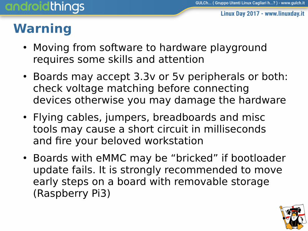
Warning● Moving from software to hardware playground
requires some skills and attention
● Boards may accept 3.3v or 5v peripherals or both: check voltage matching before connecting devices otherwise you may damage the hardware
● Flying cables, jumpers, breadboards and misc tools may cause a short circuit in milliseconds and fre your beloved workstation
● Boards with eMMC may be “bricked” if bootloader update fails. It is strongly recommended to move early steps on a board with removable storage (Raspberry Pi3)

General Purpose Input/Output (GPIO)● Digital I/O with two logical states (true/false)
mapped on two electrical states (high/low)
PeripheralManagerService pms = new PeripheralManagerService();
List<String> portList = pms.getGpioList();
mGpio = pms.openGpio(portList.get(0));
mGpio.setValue(true | false); // write
boolean state = mGpio.getValue(); // read

General Purpose Input/Output (GPIO)GpioCallback mGpioCallback = new GpioCallback() {
@Override
public boolean onGpioEdge(Gpio gpio) {
mDevice.getValue(); // Read the active low pin state
return true; // Continue listening for more interrupts
}
@Override
public void onGpioError(Gpio gpio, int error) { }
};
// EDGE_BOTH |EDGE_NONE | EDGE_RISING | EDGE_FALLING
mGpio.setEdgeTriggerType(EDGE_BOTH);
mGpio.registerGpioCallback(mGpioCallback);
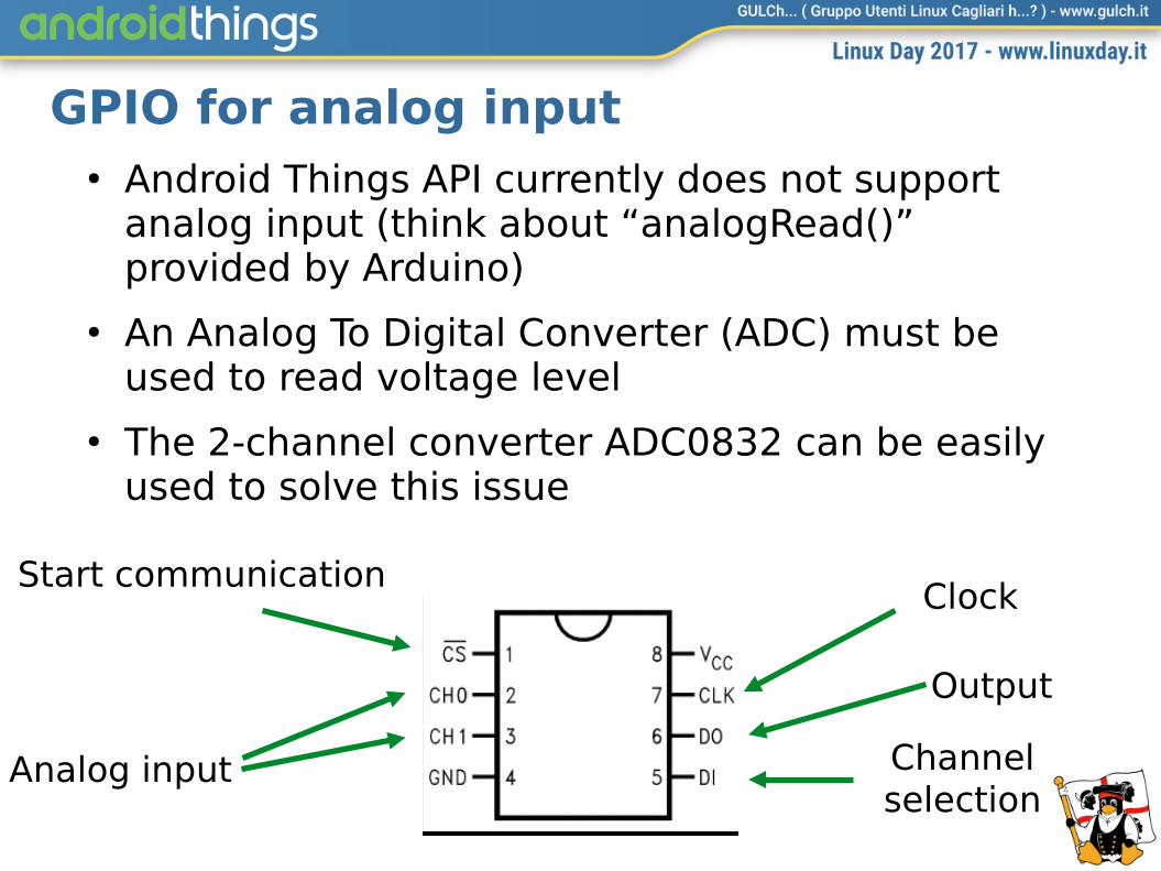
GPIO for analog input● Android Things API currently does not support
analog input (think about “analogRead()” provided by Arduino)
● An Analog To Digital Converter (ADC) must be used to read voltage level
● The 2-channel converter ADC0832 can be easily used to solve this issue
Start communication
Analog input
Clock
Output
Channelselection

Writing the ADC0832 driver [1]
// configuring GPIO connections
gpioD0.setDirection(Gpio.DIRECTION_IN);
gpioD1.setDirection(Gpio.DIRECTION_OUT_INITIALLY_HIGH);
gpioCLK.setDirection(Gpio.DIRECTION_OUT_INITIALLY_HIGH);
gpioCS.setDirection(Gpio.DIRECTION_OUT_INITIALLY_HIGH);
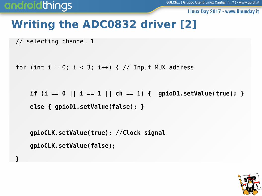
Writing the ADC0832 driver [2]
// selecting channel 1
for (int i = 0; i < 3; i++) { // Input MUX address
if (i == 0 || i == 1 || ch == 1) { gpioD1.setValue(true); }
else { gpioD1.setValue(false); }
gpioCLK.setValue(true); //Clock signal
gpioCLK.setValue(false);
}
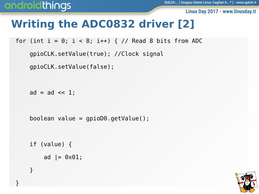
Writing the ADC0832 driver [2]
for (int i = 0; i < 8; i++) { // Read 8 bits from ADC
gpioCLK.setValue(true); //Clock signal
gpioCLK.setValue(false);
ad = ad << 1;
boolean value = gpioD0.getValue();
if (value) {
ad |= 0x01;
}
}

Writing a driver FAQ● Is this always so complicated?
– YES● Could it be simplifed?
– YES● How???
– Using a driver library :-)● Where?
– Android Things user-space drivers (by Google)– Useful Packages and Modules (UPM) and MRAA
(by Intel)
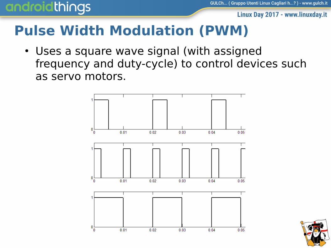
Pulse Width Modulation (PWM)● Uses a square wave signal (with assigned
frequency and duty-cycle) to control devices such as servo motors.

Pulse Width Modulation (PWM)● Values for this servo:
– 50HZ , 7.5% -> Neutral position(90°)– 50HZ , 3.75% -> Min position (0°)– 50HZ , 11.25% -> Max position (180°)
PeripheralManagerService pms = new PeripheralManagerService();
List<String> portList = pms.getPwmList(); //List of all PWM ports
Pwm mPwm = pms.openPwm(portList.get(0));
mPwm.setPwmFrequencyHz(50);
mPwm.setPwmDutyCycle(7.5);
mPwm.setEnabled(true); //start pulsing

Serial Communication: I2C, UART, SPI
PeripheralManagerService pms = new PeripheralManagerService();
List<String> mI2Cs = pms.getI2cBusList();
List<String> mUARTs = pms.getUartDeviceList();
List<String> mSPIs = pms.getSpiBusList();

Inter-Integrated Circuit (I2C)● Synchronous, fxed clock speed, half-duplex,
master-slave (SW), low boundrate
● Peripheral specs: addresses for all connected slave, addresses for all information, MSB only
● Connection:
– Shared clock signal (SCL), Shared data line (SDA)– Common ground reference (GND)
PeripheralManagerService pms = new PeripheralManagerService();
I2cDevice mI2C = pms.openI2cDevice(I2C_DEVICE_NAME, I2C_ADDRESS);
byte[] data = new byte[3];
mI2C.readRegBuffer(startAddress, data, data.length);
mI2C.writeRegBuffer (startAddress, data, data.length)

Typical I2C devices [DEMO]
Universal Asynchronous Receiver Transmitter (UART)
● Every time you see the TX-RX pair, there’s a UART available!
● The simplest serial port used for expansion boards or even home appliances (often for logging)
● Features: point to point, asynchronous (no clock), full duplex
● Peripheral specs: boudrate, parity bit, data size, stop bit
● Physical Interface: 3 basic wires TX, RX, GND + 2 optional wires: request to send (RTS) and clear to send (CTS)

UART: setupPeripheralManagerService pms = new PeripheralManagerService();
UartDevice uart = pms.openUartDevice(UART_DEVICE_NAME);
mUart.setBaudrate(115200);
// 8N1
mUart.setDataSize(8);
mUart.setParity(UartDevice.PARITY_NONE);
mUart.setStopBits(1);
//enable/disable HW flow control
mUart.setHardwareFlowControl
(UartDevice.HW_FLOW_CONTROL_AUTO_RTSCTS);
mUart.setHardwareFlowControl(UartDevice.HW_FLOW_CONTROL_NONE);
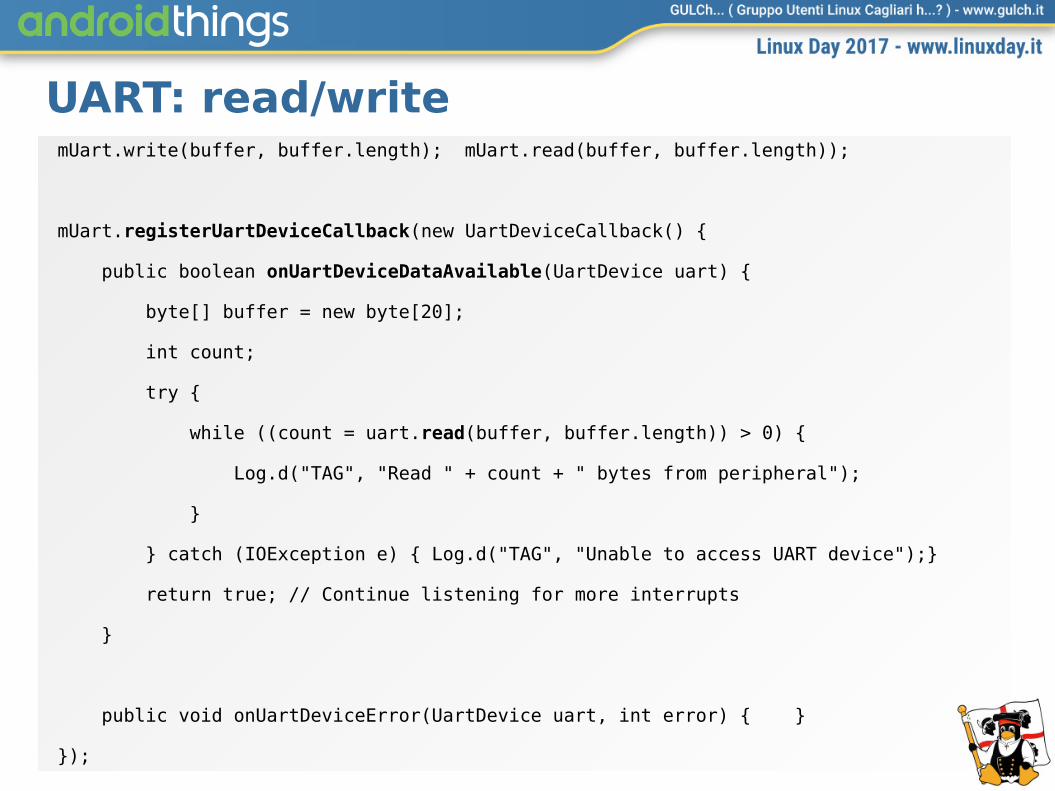
UART: read/writemUart.write(buffer, buffer.length); mUart.read(buffer, buffer.length));
mUart.registerUartDeviceCallback(new UartDeviceCallback() {
public boolean onUartDeviceDataAvailable(UartDevice uart) {
byte[] buffer = new byte[20];
int count;
try {
while ((count = uart.read(buffer, buffer.length)) > 0) {
Log.d("TAG", "Read " + count + " bytes from peripheral");
}
} catch (IOException e) { Log.d("TAG", "Unable to access UART device");}
return true; // Continue listening for more interrupts
}
public void onUartDeviceError(UartDevice uart, int error) { }
});

RFID Reader [DEMO]
+

NFC badge reader [1/3 DEMO]private void readNFC() {
try {
FirebaseDatabase database = FirebaseDatabase.getInstance();
DatabaseReference myRef = database.getReference("presenze");
PeripheralManagerService pms = new PeripheralManagerService();
UartDevice uart = pms.openUartDevice("UART1");
uart.setBaudrate(19200); uart.setDataSize(8);
uart.setParity(UartDevice.PARITY_NONE); uart.setStopBits(1);
byte[] readCMD = new byte[]{(byte) 0xAA, (byte) 0xBB, 0x02, 0x20, 0x22};
// prefix + 2 bytes
byte[] noTAG_PREFX = new byte[]{(byte) 0xAA, (byte) 0xBB, (byte) 0x02};
// prefix + 1 byte to skip + 4 bytes ID + 1 byte end
byte[] foundTAG_PREFX = new byte[]{(byte) 0xAA, (byte) 0xBB, (byte) 0x06};
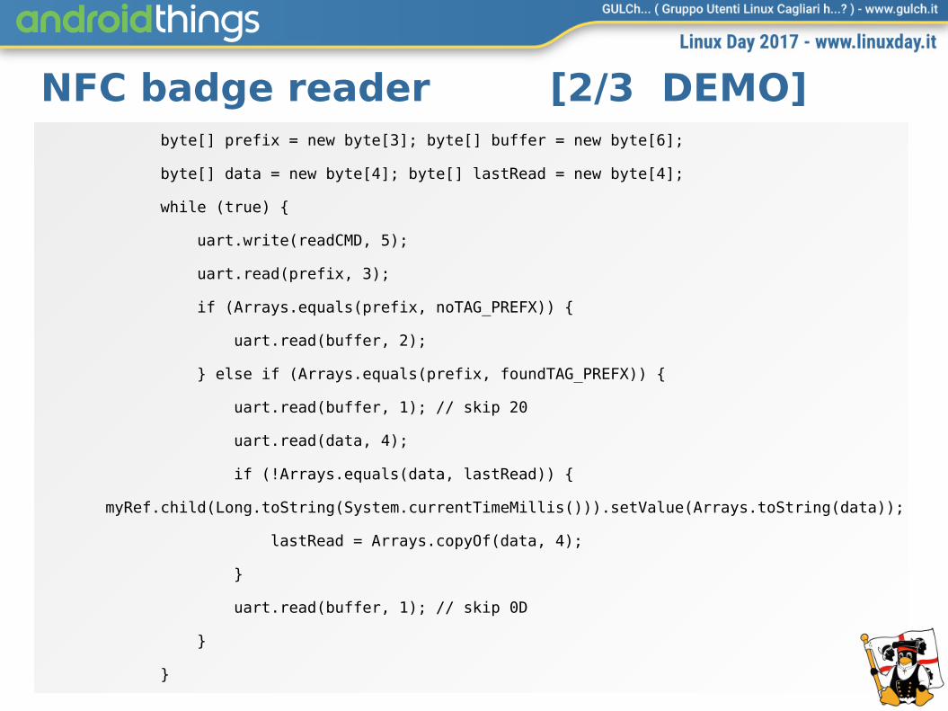
NFC badge reader [2/3 DEMO] byte[] prefix = new byte[3]; byte[] buffer = new byte[6];
byte[] data = new byte[4]; byte[] lastRead = new byte[4];
while (true) {
uart.write(readCMD, 5);
uart.read(prefix, 3);
if (Arrays.equals(prefix, noTAG_PREFX)) {
uart.read(buffer, 2);
} else if (Arrays.equals(prefix, foundTAG_PREFX)) {
uart.read(buffer, 1); // skip 20
uart.read(data, 4);
if (!Arrays.equals(data, lastRead)) {
myRef.child(Long.toString(System.currentTimeMillis())).setValue(Arrays.toString(data));
lastRead = Arrays.copyOf(data, 4);
}
uart.read(buffer, 1); // skip 0D
}
}

NFC badge reader [3/3 DEMO]
} catch (Exception e) { e.printStackTrace(); }
}
private void d(String message) { Log.d("LD17", message); }
}
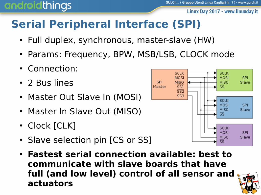
Serial Peripheral Interface (SPI)● Full duplex, synchronous, master-slave (HW)
● Params: Frequency, BPW, MSB/LSB, CLOCK mode
● Connection:
● 2 Bus lines
● Master Out Slave In (MOSI)
● Master In Slave Out (MISO)
● Clock [CLK]
● Slave selection pin [CS or SS]
● Fastest serial connection available: best to communicate with slave boards that have full (and low level) control of all sensor and actuators

SPIPeripheralManagerService pms = new PeripheralManagerService();
mSpi = pms.openSpiDevice(SPI_DEVICE_NAME);
mSpi.setMode(SpiDevice.MODE0); // MODE0 | MODE1 | MODE2 | MODE3
mSpi.setFrequency(500000); // 500 KHz
mSpi.setBitsPerWord(8); // 8 BPW
mSpi.setBitJustification(false); // MSB first
// Write & read
mSpi.write(buffer, buffer.length);
byte[] response = new byte[32];
mSpi.read(response, response.length);

48
DEXTER BrickPi● Raspberry Pi3 extension module that provides:
– 4 Mindstorms NXT/EV3 Motor ports– 4 Mindstorms NXT/EV3 Sensor ports– Extra I2C sensor bus– SPI interface to Raspberry Pi3– Uniform request/response binary protocol– Seamless power management (internal,
external, both)

Never forget to read the release notes!

Never forget to read the release notes!List<String> portList = mManager.getGpioList();
for (String gpioName: portList) {
Gpio gpio;
if (gpioName.equals("BCM4") ||
gpioName.equals("BCM5") ||
gpioName.equals("BCM6")) {
gpio = mManager.openGpio(gpioName);
gpio.setDirection(Gpio.DIRECTION_OUT_INITIALLY_LOW);
gpio.setActiveType(Gpio.ACTIVE_HIGH);
gpio.setValue(false);
gpio.close();
}
}

51
BrickPi & LEGO Rover (video)

52
Conclusion● Android Things brings the power and richness of
Android Platform to the IoT World
● Secure, portable, scalable, ready-for-the-cloud, ready-for-independence :-)
● Upcoming board with cellular network connectivity and near-to-wearable devices will open the doors to new classes of applications and services

53
Speaker● Co-founder GULCh (21 years ago…)
● Manager @ Open Reply
● Technical writer
● Linux User since 1994
● Android Developer since 2009
● Billionaire (still to come)
● Reference
– Twitter: @gerdavax– http://www.gerdavax.it – gerdavax presso la posta di Big G
54
Copyright and disclaimer● This presentation has been written by Stefano
Sanna and Giovanni Di Gialluca. It has been derived from “Android Things in action”, presented at Droidcon 2017 in Turin.
● This presentation is published under the Creative Commons License “Attribution-NonCommercial-ShareAlike 4.0 International”
● All brands, trademarks and technologies mentioned in this presentation are properties of respective owners and they have been used just for educational purpose.